X 1200 - X 1900 - Systemair · X 1200 - X 1900. 12 1 1 Product Codes X 1200 - X 1900 X 1900 UC 54...
24
Packaged Air Conditioners - Vertical Units Refrigerant R407C 12.3 to 18.0kW Air Cooled Models (AR) Water Cooled Models (AO) 1500 to 3800 m 3 /h X 1200 - X 1900
Transcript of X 1200 - X 1900 - Systemair · X 1200 - X 1900. 12 1 1 Product Codes X 1200 - X 1900 X 1900 UC 54...

Packaged Air Conditioners - Vertical Units
Refrigerant R407C
12.3 to 18.0kWAir Cooled Models (AR)Water Cooled Models (AO)
1500 to 3800 m3/h
X 1200 - X 1900

X 1200 / X 1900 1
Product Codes
X 1200 - X 1900
X 1900 UC 54
Models Power supplyProduct codesIndoor unit Outdoor unitX 1200R-407C
X 1900R-407C
UC 34 (X 1200)
UC 34TTS (X 1200)
UC 54 (X 1900)
UC 54TTS (X 1900)
AR with air cooled separated condenser
400V / 3 N ~ / 50 Hz 7XU122246 7XU122235 7XU131080 7XU131081 7XU131070 7XU131073
AO with wasted water supply 400V / 3 N ~ / 50 Hz 7XU012185 7XU012156 - - - -

X 1200 / X 19002
IntroductionWithin the context of the HCFC fluid replacement, these units have been optimized to operate with the R-407C refrigerant which contains no chlorine and has no effect on the ozone layer.
PresentationThe X 1200 and X 1900 packaged air conditioners are presented:
Single packaged for the WATER cooled models (AO). With a separate outdoor condensing unit for the AIR cooled
models (AR).
The air intake and discharge is provided :
Either directly by air intake grilles and a discharge plenum (accessory),
Or by ducts for intake and/or discharge, to be connected to the connection flanges (accessory).
This well-finished, single packaged unit combines many features such as east installation, high efficiency, quiet operation and reliability, which make it well suited for air conditioning and air filtering in offices, stores and industrial premises.
These packaged air conditioners can be equipped with:
Electric heater (integrated), (option) Hot water coil, (option) Fresh air intake (lateral or rear), (accessory) Remote control, (accessory) Air discharge plenum with double deflection (accessory).
They benefit from 30 years experience and are perfectly suited to working with :
Wasted water; its consumption being reduced to a minimum by a pressostatic valve (included in the AOP model).
Recycled water; supplied by a cooling tower or an outdoor heat exchanger.
Outside air; with the possibility of operating at very low temperatures (down to –10 °C with the "ALL SEASONS" option on the AR models).
Main features Cabinet with reduced floor dimensions, Standard ventilation : Three fan speeds (high/normal/low)
which can be pre-selected on the terminal block to adapt to the ductwork air pressure drops.
Optional "High Speed Ventilation" equipment with a single speed motor.
Vertical discharge with or without duct, or horizontal discharge with plenum (accessory).
Two air intake possibilities : On the front with grilles or on the rear with ducts, with the rear air intake (accessory).
M1 filters, mounted on a metal frame with stiffening netting. Integrated unit control (Control Panel) or remote control
(accessory). Electrical, water and refrigerant connections on the right or
left side. Cooling with wasted water with a pressostatic valve. Two heating possibilities: Integrated electric coil or hot water
heating coil. Three control possibilities : Inverting type (standard),
automatic thermostat for "heating/cooling" with neutral zone (accessory supplied with integrated electric heating) and air monitoring control (remote control accessory).
Two possibilities of refrigerant pipes (AR models) : up to 25 m maximum with factory precharged pipes (accessory) or with pipes brazed and charged on site (set of female valves supplied as an accessory for pipes up to 45 m)
Description
Bodywork : Panels and side faces made of profiled sheet steel covered
with enamel finish, baked in a high temperature oven.
Intake grilles made of modular elements in flameproof, shock resistant polystyrene, classified UL-VO according to UL94.
Insulation and protection : Thermal and acoustic insulation of the unit.
Watertight unit base for the possible collection of condensates or abnormal overflowing (e.g. condensate drain tray clogging).
Refrigerant circuit : All models
Hermetic type compressor fitted with thermal and electrical protections, linked to a factory sealed and brazed refrigerant circuit.
Pressure switches and high and low pressure tapping points.
Liquid line protected by a filter-drier (AR model).
Evaporator composed of copper tubes with aluminium fins and anti-corrosion protected condensate tray.
AO model
Coaxial condenser with counter flow circulation, equipped with finned copped tube in a steel cover.
Pressostatic valve on the water inlet for reducing water consumption to a minimum (wasted water model).
On request, the unit is supplied without a pressostatic valve but with an additional manometer pressure tapping point for independent control of the water flow (recycled water model).
AR model
Reserve liquid receiver.
Thermostatic expansion valve with pressure balancing.
Liquid indicator and valve on liquid line.
Shut off valves on indoor unit and outdoor condensing unit (UC) for refrigerant pipes.
Outdoor condensing unit with coils composed of copper tubes and aluminium fins.
Ventilation / Filters : Fan equipped with two, direct drive, centrifugal wheels with
double inlets.
Standard 3 speed fan motor (VS) switchable from the electrical terminal box (refer to electrical connections).
Specific "High Speed Ventilation" (FV) motor available as optional.
Fan-motor assembly mounted on a sliding chassis with anti-vibration seals for easy maintenance.
M1 flame retardant re-usable filters, made of synthetic fibres, with a metal frame and protective grille.
UC with single phase 230 V fan motors.
Propeller fan of UC with direct drive and low speed of rotation.

X 1200 / X 1900 3
IntroductionElectricity / Safety :Manufactured in large series, these air conditioners undergo numerous controls during fabrication and are systematically tested before delivery.
Safety devices effectively protect this equipment :
Protection of the compressor with fuses, thermal relay and electronic anti- short cycle timer.
Protection of the integrated electric heater (accessory) with fuses and dual automatic and manual reset overload protection devices.
Fuses on the control circuit.
Protection of the fan motors (VS and FV) by fuses and an internal safety device.
Low pressure pressostats with automatic reset and high pressure pressostats with manual reset.
Solenoid shut off valve on the liquid line (AR model).
Crankcase heater as standard on all models.
Protection of the UC fan motor with internal thermostat.
Mains power supply 400V / 3 N ~ / 50 Hz as standard. An option 400V / 3 ~ / 50 Hz and 230V / 3 ~ / 50 Hz.
Terminal block for single phase 230V power supply to the control circuit with a 400V / 230V transformer (not supplied) if the neutral wire is not available.
Control / Regulation : Fascia grouping the controls (Main "ON/OFF" switch with
control light – Heating "ON/OFF" and Cooling "ON/OFF") and the regulation (inverting thermostat).
Automatic cooling/heating with neutral zone thermostat supplied with the integrated electric heater accessory.
Remote control with integrated inverting thermostat with the additional possibility of ventilation control (VA or VB connection).
VA connection : Continuous ventilation during cooling and heating.
VB connection : Ventilation regulated during heating and continuous ventilation during cooling.
"ALL SEASONS" system (option) controlling the condensing pressure; allowing cooling on the AR models down to –10 °C outdoor temperature.
After sales service/Maintenance
CAUTION :Procedures for working on the refrigerant circuit, and the technical characteristics, are different from the R22. Consult the corresponding instructions and follow the recommendations when carrying out any work.
Access to the air filters is from the front after removal of the air intake grille.
All the refrigeration, electrical and ventilation devices are easily accessible from the front of the unit after removal of the front panels.
Every accessory is supplied with fitting instructions (and adjustment instructions, if necessary).
The technical data, installation instructions, maintenance and operation instructions, exploded views and spare parts lists are available on request.

X 1200 / X 19004
Technical DataModels X1200 X1900Sizes AR AO AR AORefrigerant R-407C
Charge g 1220 1260 1704 2269 Wasted water 2850 Recycled water
Cooling capacity (1)Nominal cooling capacity W 12300 15005 16200 18000Nominal cooling capacity BTU/HR 42000 51200 55300 61400Air flow
Nominal treated air m3/h 2000 2000 3200 3200Mini./maxi. treated air m3/h 1500/2500 1500/2500 2500/3800 2500/3800Nominal fresh air (with accessory) m3/h 180 180 285 285Available static pressure (2) nominal/maxi.
Standard ventilation - High speed daPa 14/20 14/20 15/30 15/30Standard ventilation - Normal speed daPa 0/13 0/13 0/21 0/21Standard ventilation - Reduced speed daPa 0/4 0/4 0/4 0/4High ventilation (optional) daPa 20/25 20/25 25/35 25/35Power input ventilation
Standard ventilation - High speed W 510 510 580 580Standard ventilation - Normal speed W 450 450 500 500Standard ventilation - Reduced speed W 260 260 380 380High ventilation (optional) W 570 570 980 980Sound pressure indoor unit (3)
High speed dBA 56 56 62 61Normal speed dBA 51 51 56 55Reduced speed dBA 48 48 52 51Power supply
Nominal voltage 400V / 3 N ~ / 50 Hz Voltage range V 360/440 360/440 360/440 360/440Total power input (1) W 4590 4625 7260 5800Circuit d'eau (1)
Wasted water - Flow L/h - 914 - 950Wasted water - Pressure drop kPa - 37 - 30Recycled water - Flow L/h - 3161 - 3050Recycled water - Pressure drop kPa - 80 - 65Outdoor condensing unit (Uc)
Model UC 34 - UC 54 -Quantity 1 - 1 -Air flow m3/h 8600 - 7600 -Power input W 530 - 611 -Sound pressure dB(A) 52 - 53 -Packing
Indoor unit - Width x Depth x Height net mm 890 x 430 x 1540 890 x 430 x 1540 1000 x 500 x 1735 1000 x 500 x 1735Indoor unit - Width x Depth x Height packed mm 940 x 495 x 1690 940 x 495 x 1690 1050 x 565 x 1890 1050 x 565 x 1890Indoor unit - Weight net/packed kg 136/145 151/160 182/195 199/212Discharge plenum - Width x Depth x Height net mm 890 x 430 x 220 890 x 430 x 220 1000 x 500 x 260 1000 x 500 x 260Discharge plenum - Width x Depth x Height packed mm 1020 x 550 x 340 1020 x 550 x 340 1120 x 620 x 380 1120 x 620 x 380Discharge plenum - Weight net/packed kg 10/12 10/12 13/15 13/15Outdoor condensing unit (UC) - Width x Depth x Height net mm 885 x 825 x 840 - 885 x 825 x 840 -Outdoor condensing unit (UC) - Width x Depth x Height packed mm 940 x 850 x 980 - 940 x 850 x 980 -Outdoor condensing unit (UC) - Weight net/packed kg 59/69 - 68/78 -Options
"High Ventilation" equipment • • • •Power supply 400V / 3 ~ / 50 Hz • • • •Power supply 230V / 3 ~ / 50 Hz (5) • • • •Electrical heater kW 9 9 12 12Hot water coil (6) kW 15.5 15.5 29.7 29.7Accessories
Front discharge plenum • • • •Fresh air intake • • • •Discharge duct connection flange • • • •Intake duct connection flange • • • •Remote control • • • •Crankcase heater standard standard standard standardFemale pipe fittings set • - • -Refrigerant pipes (25 m maxi.) • - • -(1) International standard ISO 51.51 conditions
Type A : 27°C/19°C wet bulb - Outside air : 35°C/24°C wet bulb Wasted water : inlet + 15°C - Recycled water inlet/outlet : 30°C/35°C
(2) Nominal pressure with nominal air flow with nominal voltage without accessory. Maximum pressure with minimum air flow with nominal voltage without accessory.
(3) Total sound pressure dB(A) (4m) under nominal conditions in a room of 1000m3 (reverberation 0.83s).
(4) Total sound pressure dB(A) (4 m) under nominal conditions in free field on reflecting surface.
(5) Voltage range : mini = 198V - maxi = 242V (the other electrical values are not changed).
(6) Hot water coil 90/80°C - Treated air 20°C - 50 % with nominal air flow.

X 1200 / X 1900 5
Model X 1200 AR - Air flow 2000 m3/h
BS : Dry bulb temperature (°C)BH : Wet bulb temperature (°C)PT : Total cooling capacity (W)PA : Power absorbed by the compressor (W) (without fan motor)PS : Sensible cooling capacity (W)Power absorbed by the indoor fan = 450 W
Air temperature at evaporator inlet (°C) Air temperature at condenser inlet (°C)
BH BS 15 20 25 30 35 40 45
15
PT W 12 716 12 255 11 793 11 332 10 871 10 410 9 948PA W 3 246 3 443 3 640 3 836 4 033 4 229 4 427
21 PS W 6 761 6 908 7 055 7 202 7 349 7 495 7 64223 7 761 7 929 8 098 8 267 8 436 8 604 8 77325 8 761 8 951 9 142 9 332 9 523 9 713 9 90427 9 761 9 973 10 185 11 332 10 871 10 410 9 94829 12 716 12 255 11 793 11 332 10 871 10 410 9 94831 12 716 12 255 11 793 11 332 10 871 10 410 9 948
17
PT W 13 501 13 021 12 542 12 062 11 582 11 103 10 623PA W 3 270 3 471 3 671 3 872 4 073 4 274 4 475
21 PS W 6 262 6 398 6 534 6 670 6 806 6 942 7 07823 7 327 7 487 7 646 7 805 7 964 8 124 8 28325 8 393 8 575 8 758 8 940 9 123 9 305 9 48827 9 458 9 664 9 870 10 075 10 281 10 486 10 62329 10 524 10 753 10 982 12 062 11 582 11 103 10 62331 13 405 13 021 12 542 12 062 11 582 11 103 10 623
19
PT W 14 293 13 794 13 296 12 798 12 300 11 802 11 304PA W 3 312 3 519 3 726 3 933 4 140 4 347 4 554
21 PS W 4 701 4 803 4 906 5 008 5 110 5 212 5 31423 5 833 5 960 6 086 6 213 6 340 6 467 6 59425 6 964 7 116 7 267 7 419 7 570 7 721 7 87327 8 096 8 272 8 448 8 624 8 800 8 976 9 15229 9 228 9 428 9 629 9 829 10 030 10 231 10 43131 10 359 10 584 10 810 11 035 11 260 11 485 11 304
21
PT W 15 135 14 612 14 089 13 566 13 044 12 521 11 998PA W 3 460 3 673 3 886 4 099 4 312 4 525 4 739
23 PS W 4 119 4 209 4 298 4 388 4 477 4 567 4 65625 5 319 5 435 5 550 5 666 5 782 5 897 6 01327 6 519 6 661 6 803 6 944 7 086 7 228 7 36929 7 719 7 887 8 055 8 223 8 390 8 558 8 72631 8 919 9 113 9 307 9 501 9 695 9 889 10 08333 10 119 10 339 10 559 10 779 10 999 11 219 11 439
23
PT W 15 983 15 436 14 889 14 341 13 794 13 247 12 699PA W 3 634 3 853 4 072 4 291 4 511 4 730 4 950
25 PS W 3 440 3 515 3 589 3 664 3 739 3 814 3 88827 4 709 4 811 4 914 5 016 5 118 5 221 5 32329 5 978 6 108 6 238 6 368 6 498 6 628 6 75831 7 247 7 404 7 562 7 720 7 877 8 035 8 19233 8 516 8 701 8 886 9 071 9 256 9 442 9 627
Cooling Performances
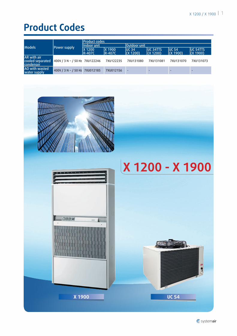
Indoor temperature °CThi 13
Tsi 17
Outdoortemperature
Without TTS °C Tse +19
With TTS* °C Tse -10
Indoor temperature °CThi 22
Tsi 32
Outdoortemperature °C Tse 47
Working range - Minimum temperature Working range - Maximum temperature
* With "All seasons kit" option
Thi : Wet bulb indoor temperature
Tsi : Dry bulb indoor temperatureTse : Dry bulb outdoor temperature
X 1200 / X 19006
Model X 1900 AR - Air flow 3200 m3/h
BS : Dry bulb temperature (°C)BH : Wet bulb temperature (°C)PT : Total cooling capacity (W)PA : Power absorbed by the compressor (W) (without fan motor)PS : Sensible cooling capacity (W)Power absorbed by the indoor fan = 500 W
Air temperature at evaporator inlet (°C) Air temperature at condenser inlet (°C)
BH BS 15 20 25 30 35 40 45
15
PT W 16 748 16 140 15 533 14 925 14 318 13 710 13 103PA W 5 301 5 622 5 943 6 264 6 585 6 906 7 228
21 PS W 10 448 10 675 10 903 11 130 11 357 11 584 11 81123 11 765 12 021 12 277 12 533 12 789 13 044 13 10325 13 083 13 367 15 461 14 925 14 318 13 710 13 10327 16 300 16 140 15 533 14 925 14 318 13 710 13 10329 16 748 16 140 15 533 14 925 14 318 13 710 13 10331 16 748 16 140 15 533 14 925 14 318 13 710 13 103
17
PT W 17 782 17 150 16 518 15 886 15 255 14 623 13 991PA W 5 340 5 668 5 995 6 323 6 651 6 979 7 307
21 PS W 10 042 10 261 10 479 10 697 10 915 11 134 11 35223 12 849 13 128 13 408 13 687 13 966 14 246 13 84125 12 849 13 128 13 408 13 687 13 966 14 246 13 84127 14 252 16 300 16 138 15 879 15 255 14 623 13 99129 16 978 16 978 16 518 15 886 15 255 14 623 13 99131 17 655 17 150 16 518 15 886 15 255 14 623 13 991
19
PT W 18 824 18 168 17 512 16 856 16 200 15 544 14 888PA W 5 408 5 746 6 084 6 422 6 760 7 098 7 436
21 PS W 8 041 8 216 8 390 8 565 8 740 8 915 9 09023 9 531 9 738 9 946 10 153 10 360 10 567 10 77425 11 022 11 261 11 501 11 740 11 980 12 220 12 45927 12 512 12 784 13 056 13 328 13 600 13 872 14 14429 14 002 14 307 14 611 14 916 15 220 15 544 14 88831 17 655 17 655 17 493 16 856 16 200 15 544 14 888
21
PT W 19 934 19 245 18 557 17 868 17 180 16 491 15 803PA W 5 649 5 997 6 345 6 693 7 041 7 389 7 738
23 PS W 7 325 7 484 7 644 7 803 7 962 8 121 8 28125 8 906 9 099 9 293 9 486 9 680 9 874 10 06727 10 486 10 714 10 942 11 170 11 398 11 626 11 85429 12 067 12 329 12 591 12 854 13 116 13 378 13 64131 13 647 13 944 14 241 14 537 14 834 15 131 15 42733 15 228 15 559 15 890 16 221 17 554 17 101 16 550
23
PT W 21 051 20 330 19 609 18 889 18 168 17 447 16 726PA W 5 933 6 291 6 649 7 007 7 366 7 724 8 082
25 PS W 6 475 6 616 6 757 6 898 7 038 7 179 7 32027 8 147 8 324 8 501 8 678 8 855 9 032 9 20929 9 818 10 032 10 245 10 459 10 672 10 885 11 09931 11 490 11 739 11 989 12 239 12 489 12 739 12 98833 13 161 13 447 13 733 14 019 14 305 14 592 14 878
Cooling Performances
Indoor temperature °CThi 13
Tsi 17
Outdoortemperature
Without TTS °C Tse +19
With TTS* °C Tse -10
Indoor temperature °CThi 22
Tsi 32
Outdoortemperature °C Tse 47
Working range - Minimum temperature Working range - Maximum temperature
* With "All seasons kit" option
Thi : Wet bulb indoor temperature
Tsi : Dry bulb indoor temperatureTse : Dry bulb outdoor temperature

X 1200 / X 1900 7
BS : Dry bulb temperature (°C)BH : Wet bulb temperature (°C)PT : Total cooling capacity (W)PA : Power absorbed by the compressor (W) (without fan motor)PS : Sensible cooling capacity (W)
Model X 1200 AO & X 1900 AO
Working range Temperature min. Temperature max.Air temperature at evaporator inlet
BH (°C) 15 23BS (°C) 21 32Water temperature (°C) 10 34
Cooling Performances
Air temperature at evaporator inlet (°C)Water consumptionSizes X 1200 X 1900
BH BS X 1200 X 1900 Models Wasted water
Recycled Water
Wasted water
Recycled Water
15
PT W 13 282 15 910 Water consumption l/h 828 3161 861 3050PA W 4 073 5 205 Inlet water temperature °C 15 29 15 29
21 PS W 8 901 10 994 Outlet water temperature °C 33.1 33.7 36.1 35.023 10 199 12 58525 11 497 14 17627 12 977 15 91029 12 977 15 91031 12 977 15 910
17
PT W 14 138 16 950 Water consumption l/h 871 3161 905 3050PA W 4 112 5 235 Inlet water temperature °C 15 29 15 29
21 PS W 8 334 10 274 Outlet water temperature °C 33.1 34.0 36.1 35.323 9 715 11 96925 11 096 13 66427 12 478 15 35929 13 813 16 95031 13 813 16 950
19
PT W 15 005 18 000 Water consumption l/h 914 3161 950 3050PA W 4 175 5 300 Inlet water temperature °C 15 29 15 29
21 PS W 6 302 7 800 Outlet water temperature °C 33.1 34.2 36.1 35.623 7 768 9 60025 9 234 11 40027 10 700 13 20029 12 166 15 00031 13 632 16 800
21
PT W 15 914 19 086 Water consumption l/h 965 3161 1003 3050PA W 4 335 5 508 Inlet water temperature °C 15 29 15 29
23 PS W 5 541 6 881 Outlet water temperature °C 33.1 34.5 36.1 35.925 7 096 8 79027 8 651 10 69829 10 206 12 60731 11 761 14 51633 13 316 16 424
23
PT W 16 833 20 182 Water consumption l/h 1017 3161 1057 3050PA W 4 518 5 751 Inlet water temperature °C 15 29 15 29
25 PS W 4 653 5 807 Outlet water temperature °C 33.1 34.8 36.1 36.327 6 298 7 82529 5 868 9 84331 5 617 11 86133 5 451 13 879
X 1200 / X 19008
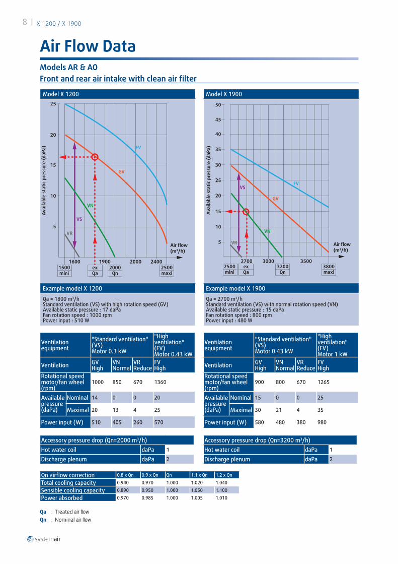
Air Flow Data
Front and rear air intake with clean air filter
Model X 1200
1500mini
2500maxi
exQa
25
20
15
10
1600 1900 2000 2400
5
2000
FV
GV
VN
VS
VR
Qn
Air flow(m3/h)
Avai
labl
e st
atic
pre
ssur
e (d
aPa)
Example model X 1200
Qa = 1800 m3/hStandard ventilation (VS) with high rotation speed (GV)Available static pressure : 17 daPaFan rotation speed : 1000 rpmPower input : 510 W
Model X 1900
2700 3000 3500
5
10
15
20
25
30
35
40
45
50
FV
GV
VN
VS
VR
2500mini
3800maxi
exQa
3200Qn
Avai
labl
e st
atic
pre
ssur
e (d
aPa)
Air flow(m3/h)
Example model X 1900
Qa = 2700 m3/hStandard ventilation (VS) with normal rotation speed (VN)Available static pressure : 15 daPaFan rotation speed : 800 rpmPower input : 480 W
Ventilation equipment
"Standard ventilation" (VS) Motor 0.3 kW
"High ventilation" (FV) Motor 0.43 kW
Ventilation GVHigh
VNNormal
VRReduce
FVHigh
Rotational speed motor/fan wheel (rpm)
1000 850 670 1360
Availablepressure (daPa)
Nominal 14 0 0 20
Maximal 20 13 4 25
Power input (W) 510 405 260 570
Accessory pressure drop (Qn=2000 m3/h)Hot water coil daPa 1
Discharge plenum daPa 2
Qa : Treated air flowQn : Nominal air flow
Ventilation equipment
"Standard ventilation" (VS) Motor 0.43 kW
"High ventilation" (FV) Motor 1 kW
Ventilation GVHigh
VNNormal
VRReduce
FVHigh
Rotational speed motor/fan wheel (rpm)
900 800 670 1265
Availablepressure (daPa)
Nominal 15 0 0 25
Maximal 30 21 4 35
Power input (W) 580 480 380 980
Accessory pressure drop (Qn=3200 m3/h)Hot water coil daPa 1
Discharge plenum daPa 2
Models AR & AO
Qn airflow correction 0.8 x Qn 0.9 x Qn Qn 1.1 x Qn 1.2 x Qn
Total cooling capacity 0.940 0.970 1.000 1.020 1.040
Sensible cooling capacity 0.890 0.950 1.000 1.050 1.100
Power absorbed 0.970 0.985 1.000 1.005 1.010

0 1 2 3 4
100
X 12
00 A
V
X 12
00 SV
X 19
00 A
V
X 1900 SV90
80
70
60
50
40
30
20
10
0
0.7 0.95 2.1 3.05
∆Pw(kPa)
100 kPa = 1 bar
Qw (m3/h)Water flow
Nominal flow
AV = WITH valve (for wasted water)SV = WITHOUT valve (for recycled water)
X 1200 / X 1900 9
Hydraulic Characteristics
Water pressure drop with pressostatic valve (AV) and without pressostatic valve (SV)
WATER SUPPLY WASTED WATER RECYCLED WATERModels X 1200 X 1900 X 1200 X 1900Water pressureMinimum kPa 50 50 - -Maximum kPa 1000 1000 1000 1000Connection on hoses - length 1 mType FEMALE NUTØ Inlet/Outlet mm F 20 x 27 F 20 x 27 F 20 x 27 F 26 x 34
Hydraulic connections - Condensate water outlets - Models AO/AR
Models X 1200/X 1900Condensate water draining hose mm Ø 20 x 25
Bottom tray outlet (for hose Ø 20 x 25 mm) Ø 7/8" (Ø 22 mm ext.)
Model AO - Condenser supply

2645
5 6 7 8 9 10 11 12 13 14 15 16 17 18 19 20
50 55 60 65 70 75 80 85 Tsi °C
Pt1kW
Twm °C
2422201816141210
86
10 12 14 16 18 20 22 24 26 28 30 32 34 36 38
X 1200
X 1900
Model X 1900Ex : Tsi = 20 °CWater = 90/80 °CTwm = 85 °CPt1 = 29.7 kW
2 3 4 51
∆Pw(kPa)
80
60
40
20
0
1.3
X 1200
X 1900
2.6
100 kPa = 1 bar10 kPa = 1 mCE
Nominal flow
Qw (m3/h)Water flow
X 1200 / X 190010
K1 coefficient air flowQa/Qn K10.80 0.870.90 0.951 11.1 1.061.2 1.13K2 coefficient ∆Tw∆Tw °K 4 6 8 10 12 14 16 18 20K2 1.05 1.03 1.01 1 0.98 0.96 0.95 0.94 0.92Water flow
Qw (m3/h) =0.86 x Pt (kW)
∆Tw
Pt1 : Total heating capacity with nominal air flow.Pt : Total heating capacity.Tsi : Dry indoor temperature.Qa : Treated air flow.Qn : Nominal air flow.Qw : Water flow.Tws : Hot water outlet temperature.Twe : Hot water inlet temperature.∆Tw : Difference in temperature water inlet/outlet.Twm : Hot water average temperature.∆Pw : Hot water pressure drops.
X 1200 X 1900Water content l 2 3
Nominal water flow m3/h 1.3 2.6
Maxi. water pressure kPa 1000 1000Maxi. water inlet temperature (Twe) °C 90 90
Mini. dry indoor temperature (Tsi) °C +6 +6
Ø connection mm M 26 x 34 M 26 x 34Water pressure drops
Heating Performance Hot Water Coil Option of models AR/AO
Anti-freeze protection
Note : Anti-freeze mandatory in summer and winter
Pt = K1 x K2 x Pt1

INTAKE
Hot watercoil
Electricalheater
DISCHARGE
INTAKE
Filter
X 1200 / X 1900 11
Filter
Models X 1200 X 1900Hot water coilNominal power input kW 15.5 29.7Nominal water flow m3/h 1.3 2.6Water pressure drop kPa 10 22Ø connections mm M 26 x 34Electrical heaterTotal power input kW 9 12Number of stages 1 1Number of stages 3 3Power input/element kW 3 4
Notes :
The electrical heater and the hot water coil can not be fitted together.
Provide for a separate regulation for the hot water coil.
The integrated electric heater is supplied with an automatic cooling/heating thermostat with neutral zone and is equipped with 2 temperature limit controls (manual/automatic).
Electrical Heater / Hot Water Coil Options
Models X 1200 X 1900
Filter type Flat with metal frame,mounted on sliding rails
Media type Flame retardant synthetic fibresNumber of filters 1 - Re-usableDimensions W x D x H mm 740 x 12 x 525 790 x 12 x 615Efficiency (1) % 83.8Eurovent/CSTB classification (2) EU3/M1
Access Air intake grilles (front)
Remark :
The filters also provide clean air from the fresh air intake (fresh air intake accessory) and the rear air intake.
(1) Test report 603 325/3 dated 05.05.76 issued by the L.N.E. (PARIS)
(2) Test report 82.18176 dated 12.05.82

0 0 0
1 2 3 4
Roomthermostat
Cool / Fan / Heat
ON / OFF
X 1200 / X 190012
Controls and RegulationControl panel
NOTE :
With the automatic "Cooling/Heating" thermostat with neutral zone supplied with the integrated electric heater, automatic operation is obtained by placing the two selection switches 2 and 3 on position 1.
Remote control (accessory)Ventilation operation
There are two possibilities :
CONTINUOUS FAN OPERATION FOR HEATING AND COOLING (VA) Fan operation is continuous in both HEATING and COOLING modes. Terminal A of the REMOTE CONTROL unit must be connected to the terminal 7 on the air conditioner (VA wiring
ON/OFF FAN OPERATION IN HEATING MODE AND CONTINUOUS OPERATION IN COOLING MODE (VB) Fan operation is regulated in HEATING mode but continuous in COOLING mode. Terminal B of the remote control unit must be connected to terminal 7 on the air conditioner (VB wiring).
Operation without electric heating
Terminal 8 of the remote control unit must be connected.
Shunt (SHC*) must be placed across terminals 13 and 14 of the air conditioner.
Operation with electric heating
Terminal 8 of the remote control unit must be connected to terminal 12 of the air conditioner.
Shunt (SHC*) must be removed and replaced by heating safety devices (FC5* and FC8*) wired in series across terminals 13 and 14 of the air conditioner.
* Reference on electrical diagram.
Heating controlIn-built electrical heater
This accessory is supplied with an automatic "Cooling/Heating" thermostat with neutral zone which replaces the ambient thermostat 4 supplied with the unit.
In the case of a remote control (accessory) the inverting thermostat pilots the cooling or the heating according to the position of the "Cooling/Heating" reversing switch (item 3 ).
Hot water heating
This accessory must be equipped with an anti-freeze safety device and a regulation system (not supplied) compatible with the installation.
1Ventilation On/Off switch0 Off1 On (with control light)
2"Cooling" selection switch0 Off1 On "Cooling"
3"Heating" selection switch0 Off1 On "Heating"
4Ambient thermostat type :Inverting thermostat (included)With neutral zone (accessory)

1
2
3
4
5
6
7
8
9
X 1200 / X 1900 13
Description of Indoor Unit
front discharge (WITH "Plenum" accessory)
VERTICAL DISCHARGE (WITHOUT accessory)
DISCHARGE WITH DUCTS (WITH "Connection flange" accessory)
9
3
5
2A
B
C
D
E
F
G
H
1
INTAKE
Fan motor assembly mountedon sliding chassis
Hot water coil(accessory)
Electric heater(accessory)
Direct expansion cooling coil(evaporator)
Filter mounted on sliding rails(fresh air and air intake)
Condensate tray
Condensate drain hose
Hermeticallysealed compressor
DISCHARGEJ
"Air dischargeconnection
flange"accessory
REAR AIR INTAKE(WITH "Air intake connection flange" accessory)
L
K
Sealing air intake grilleby rear air intake panel
"Air intakeconnection flange"
accessory
Discharge plenum (accessory) with double deflection.
Control panel.
Air intake grille.
Access panel to the fan motor removable base and the hot water coil (accessory).
Hot water coil connections and bleed. Access on the right or left side.
Connection for fresh air intake (accessory) on the right, left or rear.
Safety drain pipes of the sealed base. Access on the right or left side.
Electrical, water and refrigerant connections.
Access panel to the electrical and refrigeration compartments.
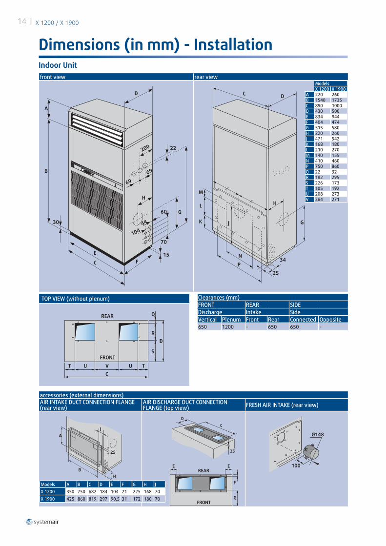
X 1200 / X 190014
Dimensions (in mm) - Installation
TOP VIEW (without plenum)
T U VC
S
RD
Q
U T
REAR
FRONT
Clearances (mm)FRONT REAR SIDEDischarge Intake SideVertical Plenum Front Rear Connected Opposite650 1200 - 650 650 -
front view rear view
1084
G
H
F
E
B
A
D
C
22
15
60
70
30
200
69
104
69
44 G
H
N34
25P
K
C D
L
J
M
ModelsX 1200 X 1900
A 220 260B 1540 1735C 890 1000D 430 500E 834 944F 404 474G 515 580H 220 260J 471 542K 168 180L 210 270M 140 155N 410 460P 750 860Q 22 32R 182 295S 226 173T 105 192U 208 273V 264 271
Indoor Unit
accessories (external dimensions)AIR INTAKE DUCT CONNECTION FLANGE (rear view)
AIR DISCHARGE DUCT CONNECTION FLANGE (top view) FRESH AIR INTAKE (rear view)
H
25
B
AJ
C
D
25
G
F
EEREAR
FRONT
Ø148
100
Models A B C D E F G H JX 1200 350 750 682 184 104 21 225 168 70X 1900 425 860 819 297 90,5 31 172 180 70

177
825 7177
Electricalcompartmentaccess panel
35
160
840671
8
INTA
KE
INTA
KE
Floor mounting and fixing
83 570 172
900
4 oblongholes 9 x 16
Clearances
0.20 m 0.60 m
0.60 m
0.60 m
Dessus : 2.50 m
X 1200 / X 1900 15
"All seasons" system - Models AR
Dimensions (in mm) - InstallationOutdoor condensing unit - Type UC 34/54 - Models AR
Models UC 34/54Air flow m3/h 5000Rotational speed ventilation tr/min 630
Sound pressure at 10 m (1) dBA 45
Power input W 611Motor coupling 230 V •
Power supply ~ 230 V - 50 Hz
(1) Sound pressure in free field on reflecting surface
The "ALL SEASONS" system permits running the air cooled units in "Cooling" position with low outdoor temperatures down to –10 °C for air conditioning of rooms with high internal heat load.
X 1200 AR + UC 34 X 1900 AR + UC 54
Accessory located in UC condensing unit including :
1 voltage inverter* References on wiring diagram.

BA
UC 54UC 34
A : Discharge line
Condensing unit
B : Liquid line
Condenser at the same level as the indoor unit
L
L maxi. = 45 mIndoor unit
Condenser
Condenser higher than the indoor unit
LH
H maxi. = 20 m(L+H) maxi. = 45 m
Indoor unit
Condenser
Condenser lower than the indoor unit
h
L
h maxi. = 9 m(L+h) maxi. = 45 m
Indoor unit
Condenser
Ø
R
X 1200 / X 190016
Refrigerant Connections - Models AR
Bending of refrigeration pipes : R ≥ Ø 3.5
Minimum slope downwards : 1 cm/m
Discharge line
Liquid line
REFRIGERANT CHARGE R-407C X 1100 X 1900AIR TREATMENTModel AR g - 1704CONDENSING UNITSType UC 34 g -Type UC 54 g - 3796Precharged refrigerant pipes (maxi. length 25 m)
Discharge lineØ - 1/2"charge - Precharged
Liquid lineØ - 3/8"charge (g/m*) - 55
MODEL AO (indoor unit)Charge g 1260 2850
(*) From 2 meters of refrigerant pipe
Notes :
For pipes between 25 and 45 m long (made on the site) the choice of the pipes (diameter) and the installation must be made professionally.
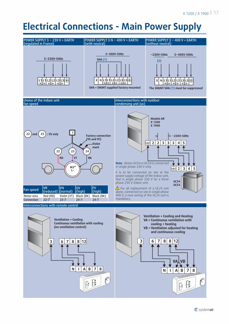
X 1200 / X 1900 17
POWER SUPPLY 3 ~ 230 V + EARTH(regulated in France)
POWER SUPPLY 3 N ~ 400 V + EARTH(with neutral)
POWER SUPPLY 3 ~ 400 V + EARTH(without neutral)
L1 L1 L2
3~230V-50Hz
L2 L3 L3 L1N
3~400V-50Hz
SHA (1)
X L1 L2 L2 L3 L3
SHA = SHUNT supplied factory mounted
(2)
3~400V-50Hz~230V-50Hz
L1NX L1 L2 L2 L3 L3
The SHUNT SHA (1) must be suppressed
interconnections with remote control
3 6
N I A B 7 8
7 8 8 12
Ventilation + CoolingContinuous ventilation with cooling(no ventilation control)
3 6
N I A B 7 8
VBVA
7 8 8 12
Ventilation + Cooling and HeatingVA = Continuous ventilation with cooling + heatingVB = Ventilation adjusted for heating and continuous cooling
choice of the indoor unitfan speed
interconnections with outdoorcondensing unit (uc)
BK
M3*1~
VTRD
22
22 7
23
23
24
Violetmark
Factory connection(VS and VF)
and : VS only
UC34UC54
~230V-50Hz
2 2 3 3 3 4 5
2 3 4 5
Models ARX 1200X 1900
Fan speed VR(reduced)
VN(normal)
GV(high)
FV(high)
Motor wire Red (RD) Violet (VT) Black (BK) Black (BK)Connection 22-7 23-7 24-7 24-7
Electrical Connections - Main Power Supply
Note : Motor UV34 or UC54 is connected in single phase 230 V only.
it is to be connected on site at the power supply voltage of the indoor unit, that is single phase 230 V for a three phase 230 V indoor unit.
For all replacement of a UC/X unit alone, connected on site in single phase 400 V, a new wiring of the UC/X unit is mandatory.

X 1200 / X 190018
Electrical Specifications - Main Power Supply
VS : Standard ventilation - FV : High ventilation.
Interconnections with outdoor unit - Model AR
Interconnections with remote control - Transformer
Sizes X 1200 X 1900
Outdoor unit UC 34 UC 54
Power supply 230 V / 1 ~ / 50 Hz 230 V / 1 ~ / 50 Hz
Nominal power input W 611 611
Maximum intensity A 3.1 3.1
Starting intensity A 5.5 5.5
Interconnection with remote control
Sizes X 1200 X 1900
Cooling + ventilation (vs/fv)
Nominal intensity A 2.1/2.8 2.4/4.7
Maximum intensity A 3/4 3/6
Starting intensity A 4/5 5/9
Heating + ventilation (vs/fv)
Nominal intensity A 2,1/2,8 2,4/4,7
Maximum intensity A 3/4 3/6
Starting intensity A 4/5 5/9
Transformer (not supplied) for power supply 3~400V+earth, without neutralModels AO ARNominal power single phase transformer 400 V / 230 V in VA
VS 630 1000
FVX 1200 1000 1000
X 1900 1600 1600
1200 1900230V/3 ~/50 Hz 400V/3 ~ + N/50 Hz 230V/3 ~/50 Hz 400V/3 ~ + N/50 Hz
NOMINAL POWER INPUT (VS/FV)Cooling mode XAR kW TBD 4.2/4.4 TBD 5.7/6.2Cooling mode XAOP kW TBD 3.8/4 TBD 5.1/5.6Cooling mode XAOR kW TBD 3.8/4 TBD 4.6/5.1Electrical heating mode kW TBD 9.4/9.6 TBD 12.5/13
COOL-ONLY UNIT (VS/FV)Maximum intensity A TBD 13/14 TBD 15/18Starting intensity A TBD 38/39 TBD 76/79Fuse rating A aM TBD 16 TBD 16/20
COOL-ONLY UNIT WITH ELECTRICAL HEATING (VS/FV)Maximum intensity A TBD 19/20 TBD 23/26Starting intensity A TBD 38/39 TBD 76/79Fuse rating A aM TBD 20 TBD 25/32

X 1200 / X 1900 19
Notes

X 1200 / X 190020
Notes


october 2015
Syst
emai
r · E
DM X
ARXA
O1-
S-3G
B/10
.15
- Su
pers
edes
EDM
XAR
XAO
1-S-
2GB/
11.1
4As
par
t of o
ur o
ngoi
ng p
rodu
ct im
prov
emen
t pro
gram
me,
our
pro
duct
s ar
e su
bjec
t to
chan
ge w
ithou
t prio
r not
ice.
Non
con
trac
tual
pho
tos.
Systemair AC SAS · route de Verneuil, 27570 Tillières-sur- Avre · Tél. 02 32 60 61 00 · Fax 02 32 32 55 13www.systemair.fr