Www.infotech.monash.edu FIT 1005 Networks & Data Communications Lecture 9 – High Speed LANs...
34
www.infotech.monash.edu FIT 1005 Networks & Data Communications Lecture 9 – Lecture 9 – High Speed High Speed LAN LANs Reference: Chapter 16 Data and Computer Communications Eighth Edition by William Stallings Lecture slides by Lawrie Brown Modified Lecture Slides:: http://users.monash.edu.au/~amkhan/fit1005/
-
Upload
christiana-lindsey -
Category
Documents
-
view
214 -
download
0
Transcript of Www.infotech.monash.edu FIT 1005 Networks & Data Communications Lecture 9 – High Speed LANs...
www.infotech.monash.edu
FIT 1005 Networks & Data Communications
Lecture 9 – Lecture 9 – High Speed High Speed LANLANss
Reference: Chapter 16
Data and Computer Communications
Eighth Edition
by William Stallings
Lecture slides by Lawrie Brown
Modified Lecture Slides::
http://users.monash.edu.au/~amkhan/fit1005/
www.infotech.monash.edu
2
Introduction
• range of technologies– Fast and Gigabit Ethernet– Fibre Channel– High Speed Wireless LANs
www.infotech.monash.edu
3
Why High Speed LANs?
• speed and power of PCs has risen– graphics-intensive applications and GUIs
• LANs are seen as essential to organizations– for client/server computing
• now have requirements for– centralized server farms– power workgroups– high-speed local backbone
www.infotech.monash.edu
4
Ethernet (CSMA/CD)
• most widely used LAN standard• developed by
– Xerox - original Ethernet– IEEE 802.3
• Carrier Sense Multiple Access with Collision Detection (CSMA/CD)
– random / contention access to media
www.infotech.monash.edu
5
ALOHA
• developed for packet radio nets
• when station has frame, it sends
• then listens for a bit over max round trip time
– if it receive ACK then fine
– if not, it retransmit
– if no ACK after repeated transmissions, give up
• uses a frame check sequence (as in HDLC)
• frame may be damaged by noise or by another station transmitting at the same time (collision)
• any overlap of frames causes collision
• Very simple scheme and hence pay’s penalty of max utilization of 18%
Aloha - (From the Hawaiian greeting) A system of contention resolution devised at The University of Hawaii. Packets are broadcast when ready, the sender listens to see if they collide and if so re-transmits after a random time.
www.infotech.monash.edu
6
Slotted ALOHA
• To improve efficiency on ALOHA (pure) we have slotted ALOHA
• time on channel is based on uniform slots equal to frame transmission time
– need central clock (or other sync mechanism)
• transmission begins at slot boundary
– frames will either miss or overlap totally
– this increases max utilization to 37%
• Both (pure aloha and slotted aloha) have poor utilization
• fail to use the fact that propagation time is much less than frame transmission time
www.infotech.monash.edu
7
CSMA
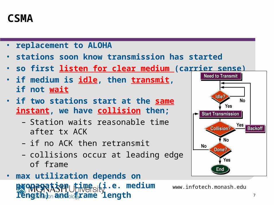
• replacement to ALOHA• stations soon know transmission has started• so first listen for clear medium (carrier sense)• if medium is idle, then transmit, if not wait• if two stations start at the same instant, we
have collision then;– Station waits reasonable time after tx ACK– if no ACK then retransmit– collisions occur at leading edge of frame
• max utilization depends on propagation time (i.e. medium length) and frame length
www.infotech.monash.edu
8
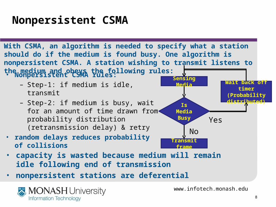
Nonpersistent CSMA
• Nonpersistent CSMA rules:– Step-1: if medium is idle, transmit– Step-2: if medium is busy, wait for an
amount of time drawn from probability distribution (retransmission delay) & retry
• random delays reduces probability of collisions
Sensing Media
Transmit frame
Wait back off timer (Probability
distributed)Is
Media Busy Yes
No
• capacity is wasted because medium will remain idle following end of transmission
• nonpersistent stations are deferential
With CSMA, an algorithm is needed to specify what a station should do if the medium is found busy. One algorithm is nonpersistent CSMA. A station wishing to transmit listens to the medium and obeys the following rules:
www.infotech.monash.edu
9
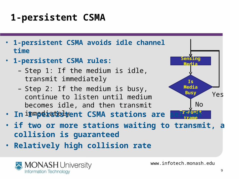
1-persistent CSMA
• 1-persistent CSMA avoids idle channel time
• 1-persistent CSMA rules:
– Step 1: If the medium is idle, transmit immediately
– Step 2: If the medium is busy, continue to listen until medium becomes idle, and then transmit immediately
Sensing Media
Transmit frame
Is Media Busy Yes
No
• In 1-persistent CSMA stations are selfish
• if two or more stations waiting to transmit, a collision is guaranteed
• Relatively high collision rate
www.infotech.monash.edu
10
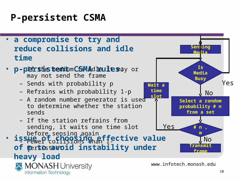
P-persistent CSMA
• a compromise to try and reduce collisions and idle time
• p-persistent CSMA rules:
Sensing Media
Transmit frame
Select a random probability # n from a
set
Is Media Busy
Yes
No
# n , m
Wait a time slot
Yes
No
– If the medium is idle it may or may not send the frame
– Sends with probability p– Refrains with probability 1-p– A random number generator is used to
determine whether the station sends– If the station refrains from sending, it waits
one time slot before sensing again– Fewer collisions than 1-Persistent
• issue of choosing effective value of p to avoid instability under heavy load
www.infotech.monash.edu
11
Value of p?
• have n stations waiting to send• at end of tx, expected no of stations is np
– if np > 1 on average there will be a collision
• repeated tx attempts mean collisions is likely• eventually when all stations trying to send have
continuous collisions hence zero throughput• thus we want np<1 for expected peaks of n
– if heavy load expected, then p is small– but smaller p means stations wait longer
www.infotech.monash.edu
12
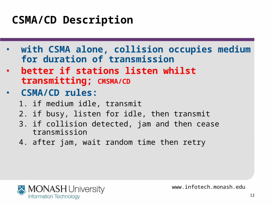
CSMA/CD Description
• with CSMA alone, collision occupies medium for duration of transmission
• better if stations listen whilst transmitting; CMSMA/CD
• CSMA/CD rules:1. if medium idle, transmit2. if busy, listen for idle, then transmit3. if collision detected, jam and then cease transmission4. after jam, wait random time then retry
www.infotech.monash.edu
13
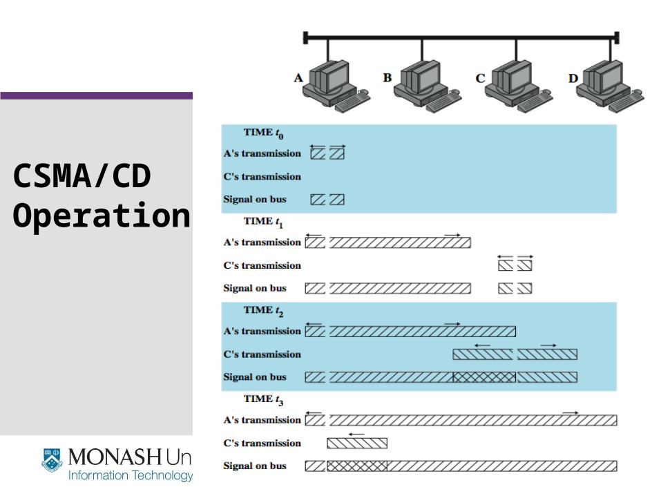
CSMA/CDOperation
www.infotech.monash.edu
14
Which Persistence Algorithm?
• IEEE 802.3 uses 1-persistent• both nonpersistent and p-persistent have
performance problems• 1-persistent seems more unstable than p-persistent
– because of greed of the stations– Time wasted due to collisions – with random back-off time the stations are unlikely to collide
on next attempt to send
www.infotech.monash.edu
15
Binary Exponential Backoff
• for backoff stability, IEEE 802.3 and Ethernet both use binary exponential backoff
• stations repeatedly resend when collide– For first 10 retransmission attempts, mean-random delay is
doubled– The mean value then remains same for 6 further attempts– after 16 unsuccessful attempts, station gives up and reports
error
• 1-persistent algorithm with binary exponential backoff is efficient over wide range of loads
• but backoff algorithm has last-in, first-out effect(stations with no or few collisions will have a chance to transmit before stations that have waited longer)
www.infotech.monash.edu
16
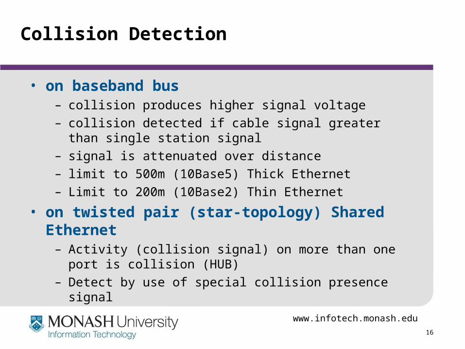
Collision Detection
• on baseband bus – collision produces higher signal voltage– collision detected if cable signal greater than single
station signal– signal is attenuated over distance– limit to 500m (10Base5) Thick Ethernet– Limit to 200m (10Base2) Thin Ethernet
• on twisted pair (star-topology) Shared Ethernet– Activity (collision signal) on more than one port is collision
(HUB)– Detect by use of special collision presence signal
www.infotech.monash.edu
17
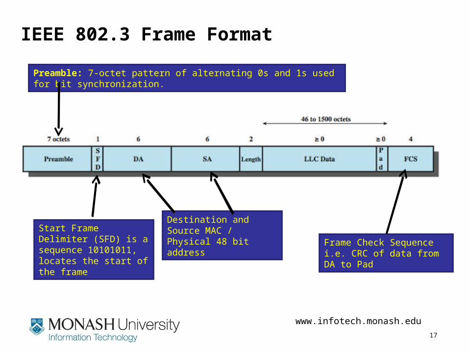
IEEE 802.3 Frame Format
Preamble: 7-octet pattern of alternating 0s and 1s used for bit synchronization.
Start Frame Delimiter (SFD) is a sequence 10101011, locates the start of the frame
Destination and Source MAC / Physical 48 bit address
Frame Check Sequencei.e. CRC of data from DA to Pad
www.infotech.monash.edu
18
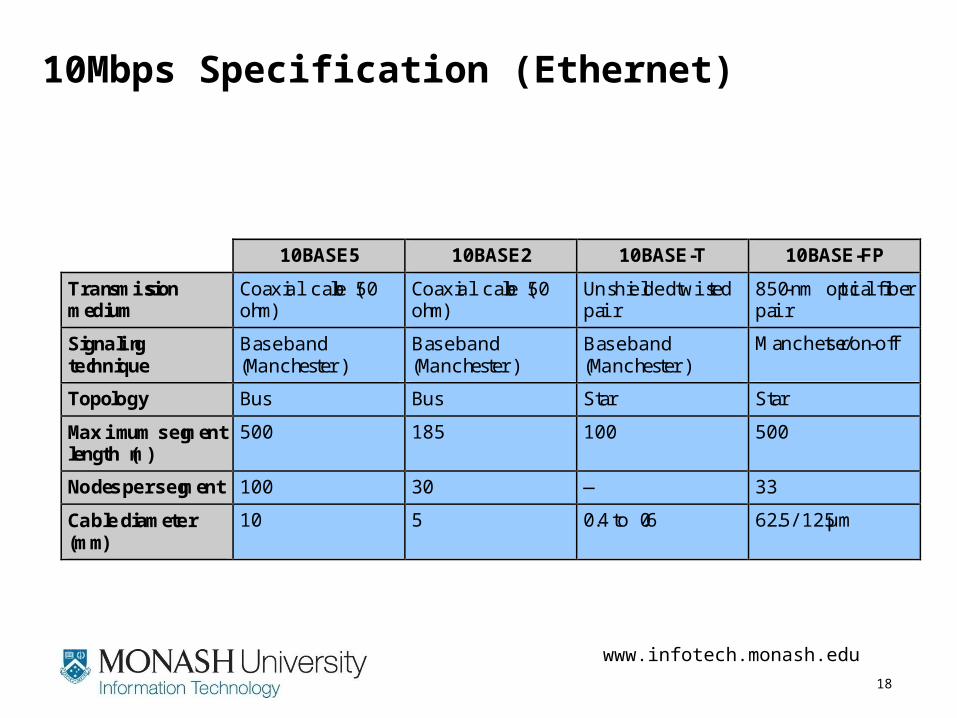
10Mbps Specification (Ethernet)
10BASE5 10BASE2 10BASE-T 10BASE-FP
Transmissionmedium
Coaxial cable (50ohm)
Coaxial cable (50ohm)
Unshielded twistedpair
850-nm optical fiberpair
Signalingtechnique
Baseband(Manchester)
Baseband(Manchester)
Baseband(Manchester)
Manchester/on-off
Topology Bus Bus Star Star
Maximum segmentlength (m)
500 185 100 500
Nodes per segment 100 30 — 33
Cable diameter(mm)
10 5 0.4 to 0.6 62.5/125 µm
www.infotech.monash.edu
19
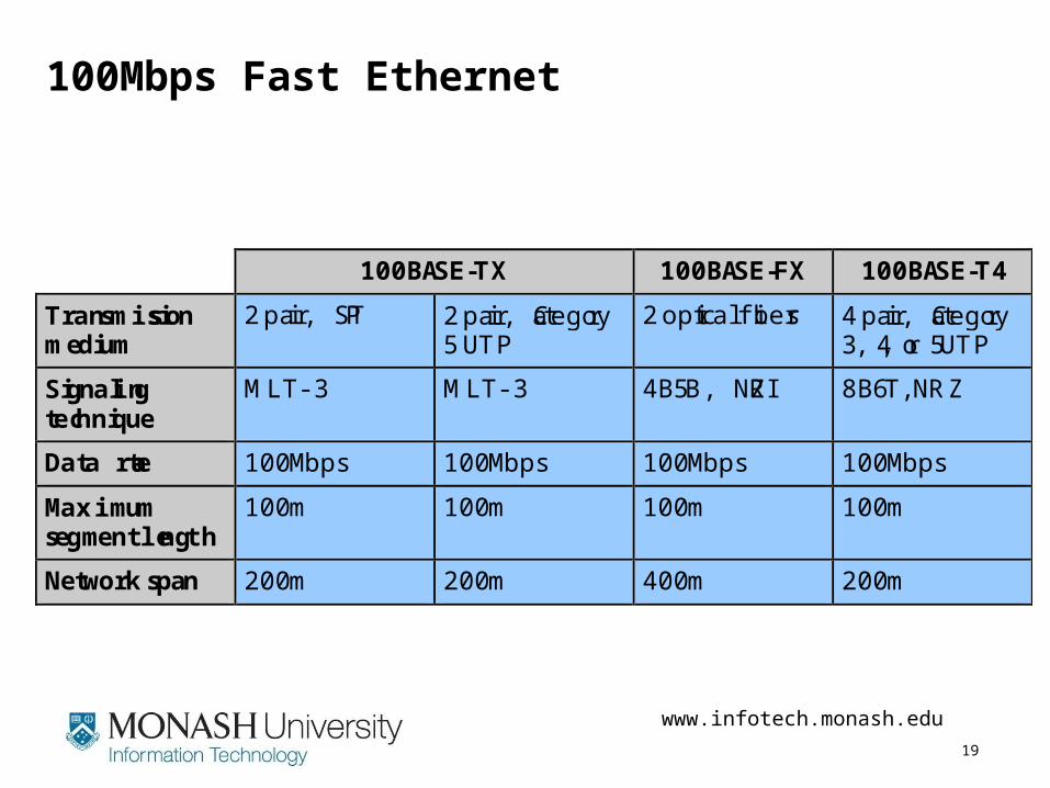
100Mbps Fast Ethernet
100BASE-TX 100BASE-FX 100BASE-T4
Transmissionmedium
2 pair, STP 2 pair, Category5 UTP
2 optical fibers 4 pair, Category3, 4, or 5 UTP
Signalingtechnique
MLT -3 MLT -3 4B5B, NRZI 8B6T, NRZ
Data rate 100 Mbps 100 Mbps 100 Mbps 100 Mbps
Maximumsegment length
100 m 100 m 100 m 100 m
Network span 200 m 200 m 400 m 200 m
www.infotech.monash.edu
20
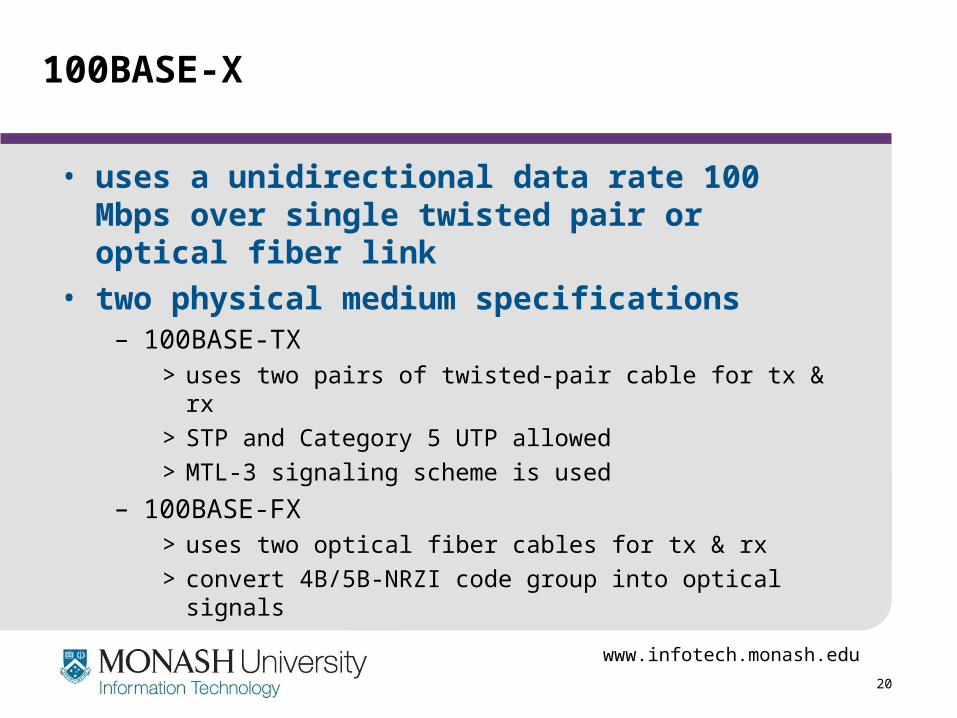
100BASE-X
• uses a unidirectional data rate 100 Mbps over single twisted pair or optical fiber link
• two physical medium specifications– 100BASE-TX
> uses two pairs of twisted-pair cable for tx & rx
> STP and Category 5 UTP allowed
> MTL-3 signaling scheme is used
– 100BASE-FX> uses two optical fiber cables for tx & rx
> convert 4B/5B-NRZI code group into optical signals
www.infotech.monash.edu
21
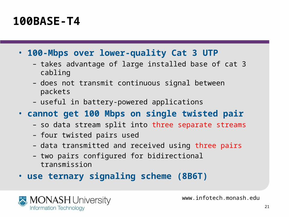
100BASE-T4
• 100-Mbps over lower-quality Cat 3 UTP– takes advantage of large installed base of cat 3 cabling– does not transmit continuous signal between packets– useful in battery-powered applications
• cannot get 100 Mbps on single twisted pair– so data stream split into three separate streams– four twisted pairs used– data transmitted and received using three pairs– two pairs configured for bidirectional transmission
• use ternary signaling scheme (8B6T)
www.infotech.monash.edu
22
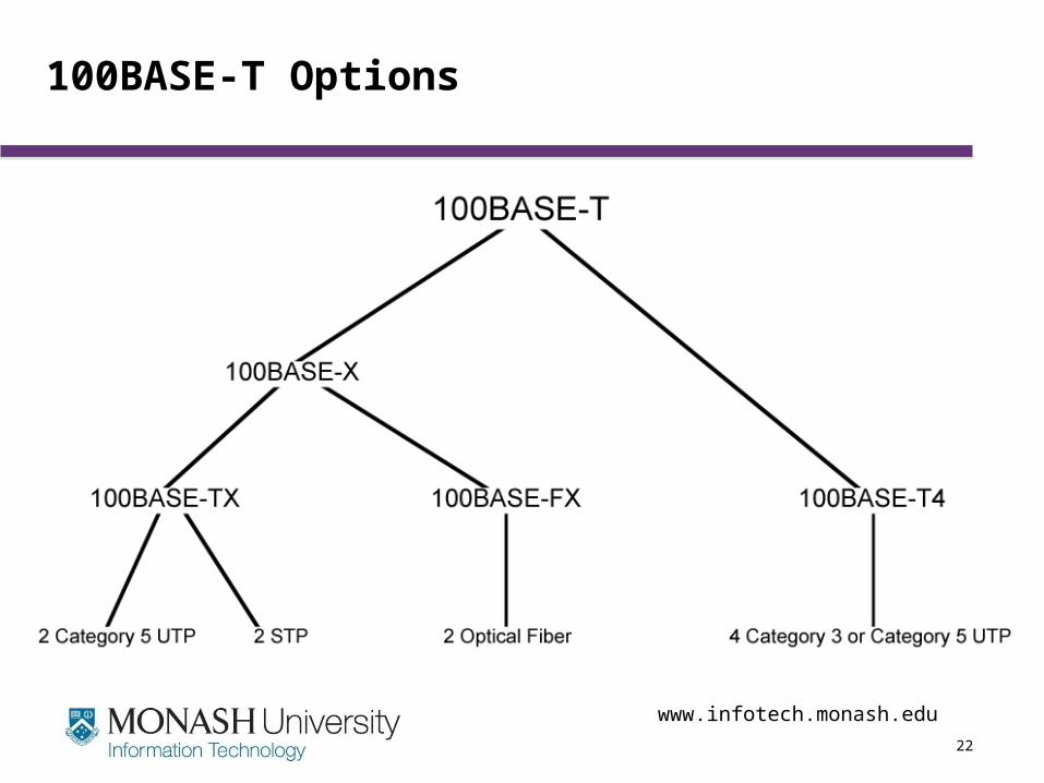
100BASE-T Options
www.infotech.monash.edu
23
Full Duplex Operation
• traditional Ethernet was only half duplex• using full-duplex, station can transmit and
receive simultaneously• 100-Mbps Ethernet in full-duplex mode, giving a
theoretical transfer rate of 200 Mbps• stations must have full-duplex adapter cards• and must use switching (switch)
– each station constitutes separate collision domain– CSMA/CD algorithm no longer needed– 802.3 MAC frame format used
www.infotech.monash.edu
24
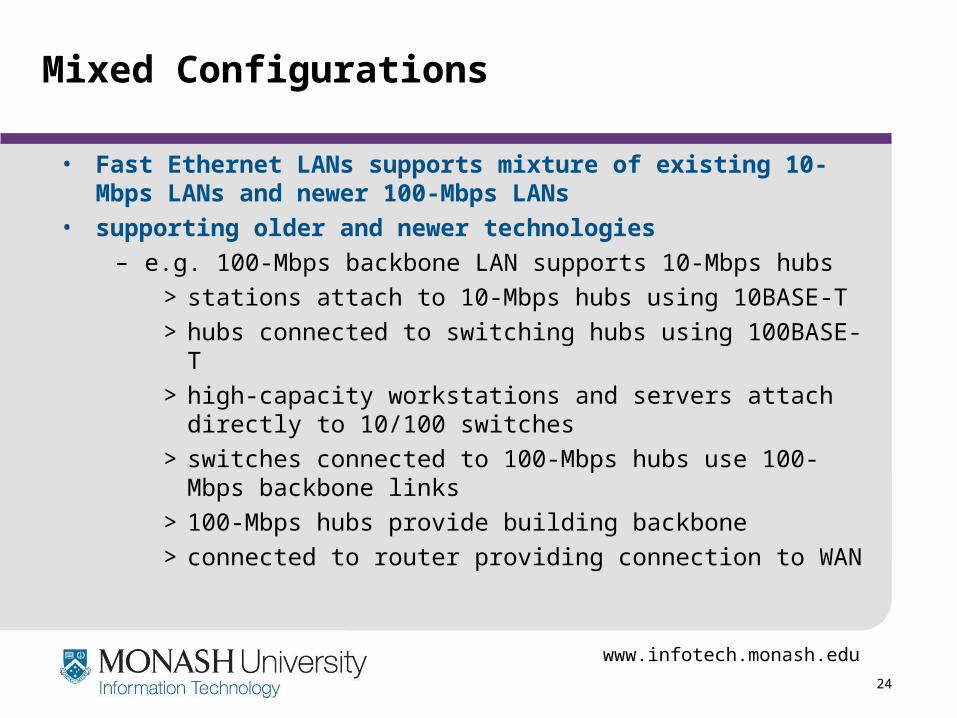
Mixed Configurations
• Fast Ethernet LANs supports mixture of existing 10-Mbps LANs and newer 100-Mbps LANs
• supporting older and newer technologies
– e.g. 100-Mbps backbone LAN supports 10-Mbps hubs
> stations attach to 10-Mbps hubs using 10BASE-T
> hubs connected to switching hubs using 100BASE-T
> high-capacity workstations and servers attach directly to 10/100 switches
> switches connected to 100-Mbps hubs use 100-Mbps backbone links
> 100-Mbps hubs provide building backbone
> connected to router providing connection to WAN
www.infotech.monash.edu
25
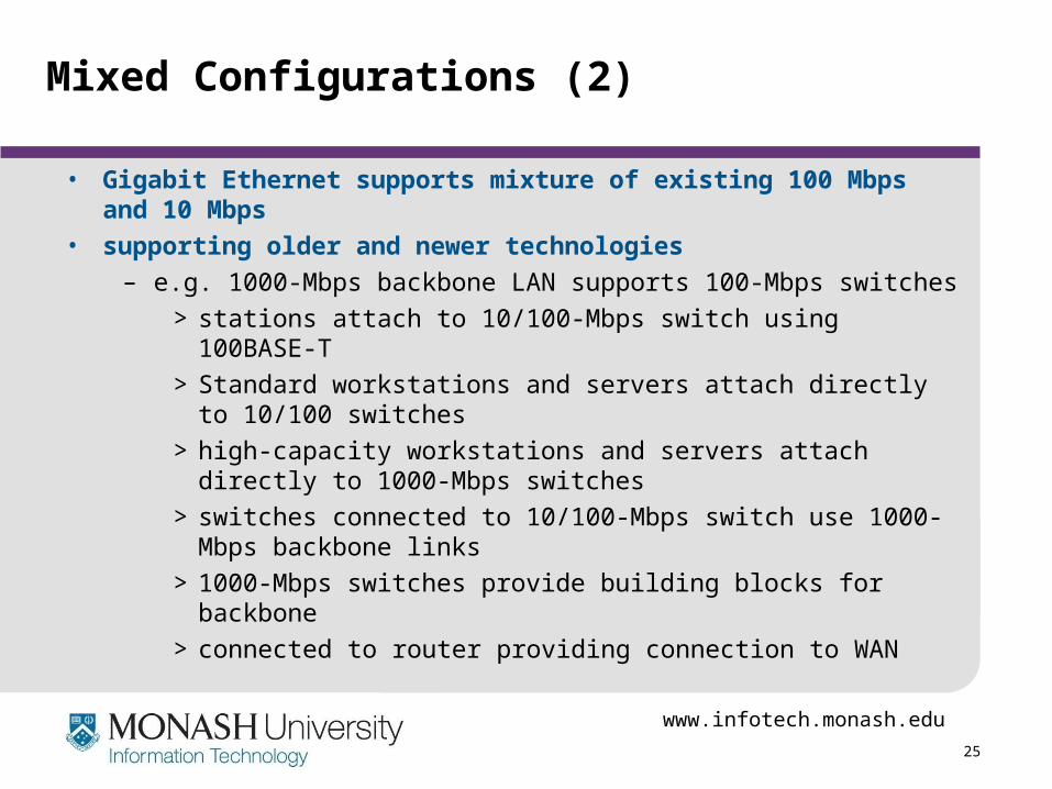
Mixed Configurations (2)
• Gigabit Ethernet supports mixture of existing 100 Mbps and 10 Mbps
• supporting older and newer technologies
– e.g. 1000-Mbps backbone LAN supports 100-Mbps switches
> stations attach to 10/100-Mbps switch using 100BASE-T
> Standard workstations and servers attach directly to 10/100 switches
> high-capacity workstations and servers attach directly to 1000-Mbps switches
> switches connected to 10/100-Mbps switch use 1000-Mbps backbone links
> 1000-Mbps switches provide building blocks for backbone
> connected to router providing connection to WAN
www.infotech.monash.edu
26
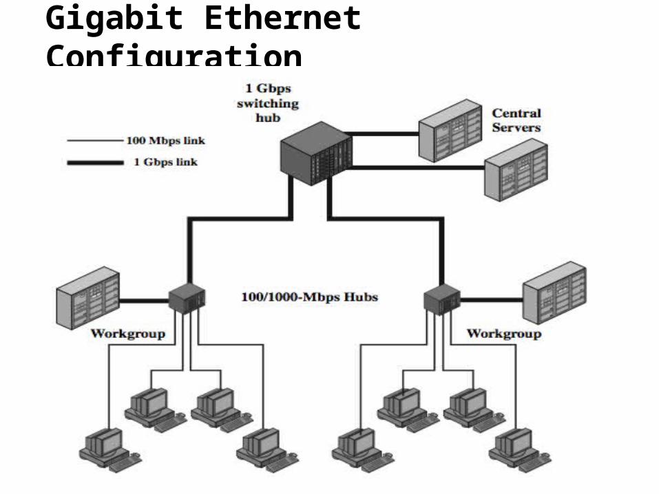
Gigabit Ethernet Configuration
www.infotech.monash.edu
27
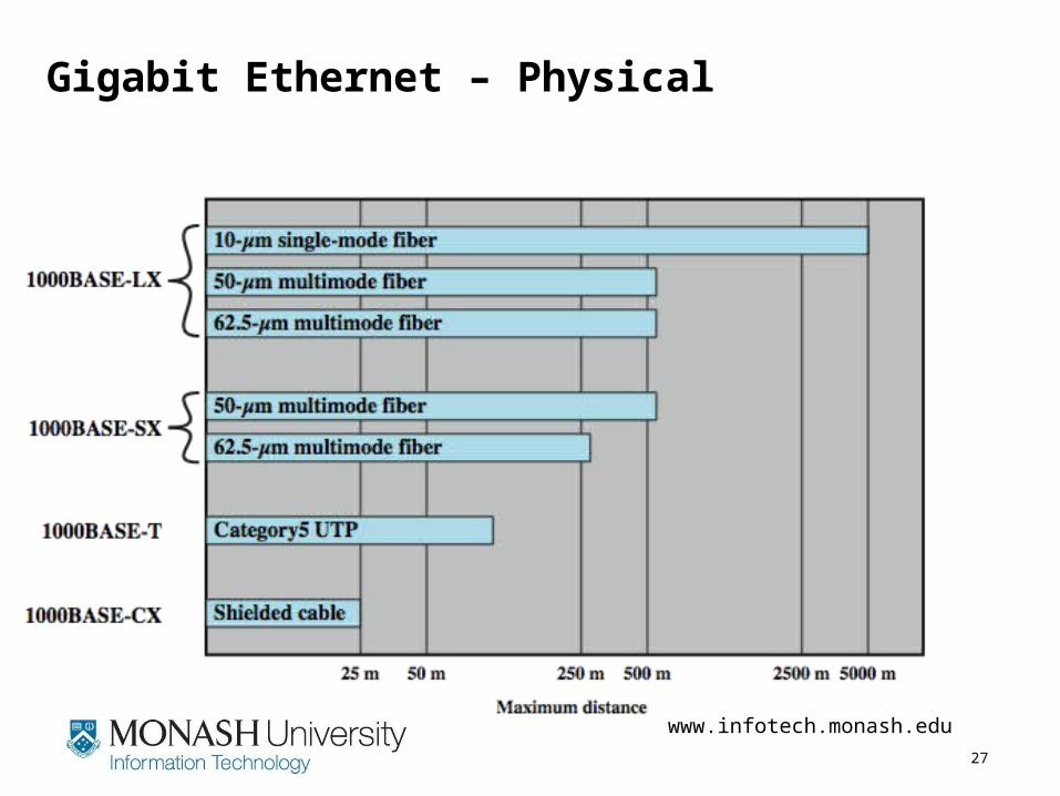
Gigabit Ethernet – Physical
www.infotech.monash.edu
28
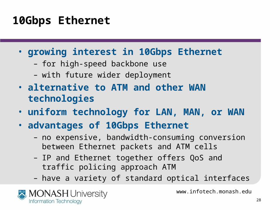
10Gbps Ethernet
• growing interest in 10Gbps Ethernet– for high-speed backbone use– with future wider deployment
• alternative to ATM and other WAN technologies• uniform technology for LAN, MAN, or WAN• advantages of 10Gbps Ethernet
– no expensive, bandwidth-consuming conversion between Ethernet packets and ATM cells
– IP and Ethernet together offers QoS and traffic policing approach ATM
– have a variety of standard optical interfaces
www.infotech.monash.edu
29
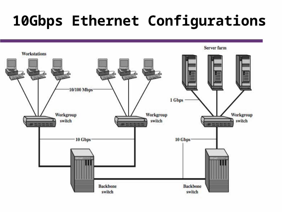
10Gbps Ethernet Configurations
www.infotech.monash.edu
30
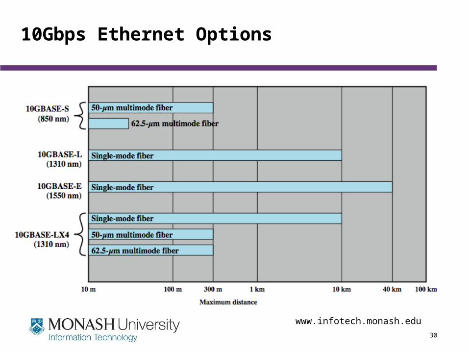
10Gbps Ethernet Options
www.infotech.monash.edu
31
Summary
• High speed LANs emergence• Ethernet technologies
– CSMA & CSMA/CD media access– 10Mbps ethernet– 100Mbps ethernet– 1Gbps ethernet– 10Gbps ethernet
www.infotech.monash.edu
32
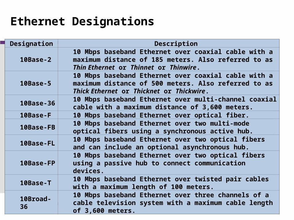
Ethernet Designations
Designation Description
10Base-2 10 Mbps baseband Ethernet over coaxial cable with a maximum distance of 185 meters. Also referred to as Thin Ethernet or Thinnet or Thinwire.
10Base-5 10 Mbps baseband Ethernet over coaxial cable with a maximum distance of 500 meters. Also referred to as Thick Ethernet or Thicknet or Thickwire.
10Base-36 10 Mbps baseband Ethernet over multi-channel coaxial cable with a maximum distance of 3,600 meters.
10Base-F 10 Mbps baseband Ethernet over optical fiber.
10Base-FB 10 Mbps baseband Ethernet over two multi-mode optical fibers using a synchronous active hub.
10Base-FL 10 Mbps baseband Ethernet over two optical fibers and can include an optional asynchronous hub.
10Base-FP 10 Mbps baseband Ethernet over two optical fibers using a passive hub to connect communication devices.
10Base-T 10 Mbps baseband Ethernet over twisted pair cables with a maximum length of 100 meters.
10Broad-36 10 Mbps baseband Ethernet over three channels of a cable television system with a maximum cable length of 3,600 meters.
www.infotech.monash.edu
33
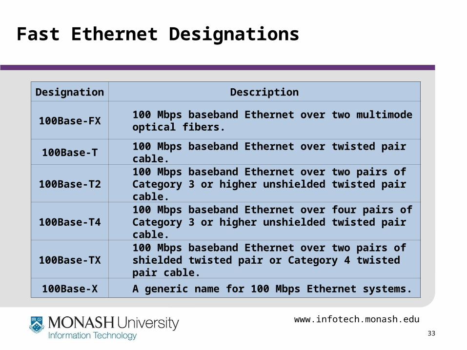
Fast Ethernet Designations
Designation Description
100Base-FX 100 Mbps baseband Ethernet over two multimode optical fibers.
100Base-T 100 Mbps baseband Ethernet over twisted pair cable.
100Base-T2 100 Mbps baseband Ethernet over two pairs of Category 3 or higher unshielded twisted pair cable.
100Base-T4 100 Mbps baseband Ethernet over four pairs of Category 3 or higher unshielded twisted pair cable.
100Base-TX 100 Mbps baseband Ethernet over two pairs of shielded twisted pair or Category 4 twisted pair cable.
100Base-X A generic name for 100 Mbps Ethernet systems.
www.infotech.monash.edu
34
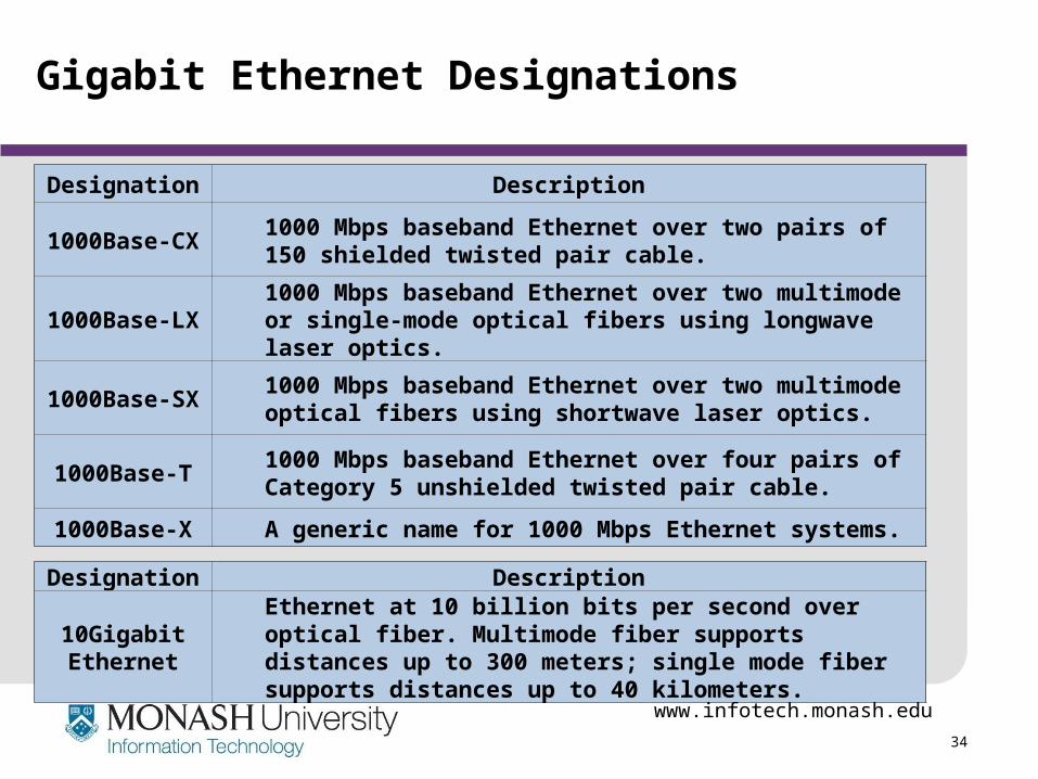
Gigabit Ethernet Designations
Designation Description
1000Base-CX 1000 Mbps baseband Ethernet over two pairs of 150 shielded twisted pair cable.
1000Base-LX 1000 Mbps baseband Ethernet over two multimode or single-mode optical fibers using longwave laser optics.
1000Base-SX 1000 Mbps baseband Ethernet over two multimode optical fibers using shortwave laser optics.
1000Base-T 1000 Mbps baseband Ethernet over four pairs of Category 5 unshielded twisted pair cable.
1000Base-X A generic name for 1000 Mbps Ethernet systems.
Designation Description
10Gigabit Ethernet
Ethernet at 10 billion bits per second over optical fiber. Multimode fiber supports distances up to 300 meters; single mode fiber supports distances up to 40 kilometers.