WWARNING!ARNINGDO NOT CONNECT DIRECTLY TO … · di-0904 12v 20w cv di-jbox-lps di-0918 12v 35w cv...
4
DRY LOCATION 1 OF 4 IG102616-2.0 ® INSTALLATION GUIDE LO-PRO ® JUNCTION BOX/LED DRIVER LO-PRO ® J-BOX/DRIVER INSTALLATION GUIDE #1) UL 1598 (UL# E469769) LED LOW VOLTAGE POWER UNIT CERTIFIED AS A LISTED LED LOW VOLTAGE POWER UNIT. OPTIONAL - ONLY APPLIES WHEN PURCHASED AS A DRIVER & J-BOX BUNDLE. SEE SPEC SHEET OR WEBSITE FOR ORDERING OPTIONS. A UL E469769 STICKER WILL BE PLACED ON THE OUTSIDE OF THE LO-PRO BOX CERTIFYING THE BUNDLE AS AN LED LOW VOLTAGE POWER UNIT. IMPORTANT SAFETY INSTRUCTIONS 1. Read all instrucons. 2. Install in accordance with naonal and local electrical code regulaons. 3. This product is intended to be installed and serviced by a qualified, licensed electrician. 4. For cabinet and surface mount use only. 5. Do not install outdoors or in wet locaons. For indoor and dry use only. 6. Do not conceal or extend exposed conductors through a building wall. 7. For low voltage exposed insulated conductor systems required by 30.1(c) of UL 2108 do not install any part of this system less than 7 feet (2.2m) above the floor. 8. To reduce the risk of fire and burns, do not install this lighng system where the exposed bare conductors can be shorted or contact any conducve materials. 9. To reduce the risk of fire and overheang, make sure all connecons are ght. 10. Do not install any luminaire closer than 6 inches (15.25cm) from any curtain, or similar combusble materials. 11. Turn off electrical power before modifying the lighng system in any way. SAVE THESE INSTRUCTIONS CERTIFIED CLASS 2 DRIVERS W WARNING! ALWAYS TURN OFF MAIN POWER BEFORE INSTALLING & SERVICING! Ensure to read all Safety and Installaon Instrucons thoroughly! Indicates 12V or 24V Indicates waage output 10-60W for 12V Class 2 models or 10-80W for 24V Class 2 models List subject to change. See Lo-Pro J-Box Product page for most recent list. Contact Diode LED Technical Support for OEM models if required. Indicates luminaire family, CCT, CRI, LENGTH LO-PRO JUNCTION BOX HAS 3 UL CERTIFICATIONS OUTLINED BELOW TO COVER A VARIETY OF APPLICATIONS. #1 IS OPTIONAL. #2 AND #3 ALWAYS APPLY: #2) UL 508A (UL# E486215) INDUSTRIAL CONTROL PANEL TYPE 1 ENCLOSURE - INDOOR. CAN BE USED AS A STANDARD J-BOX FOR ANY COMPONENT. THIS CERT ALWAYS APPLIES TO THE LO-PRO BOX. #3) UL 1598 (UL# E485321) LUMINAIRE FITTING CAN BE USED AS A FITTING WITH OUR WITHOUT CLASS 2 LED DRIVER MODELS AND LIGHTING SYSTEMS OUTLINED BELOW. THIS CERT ALWAYS APPLIES TO THE LO-PRO BOX. DIODE LED DRIVER SKU* DESCRIPTION LO-PRO BOX DI-TD-xxV-yyW OMNIDRIVE Dimmable Driver -LPS (10-35W) -LPL (45-80W) DI-0904 12V 20W CV DI-JBOX-LPS DI-0918 12V 35W CV DI-JBOX-LPS DI-0906 12V 60W CV DI-JBOX-LPS DI-0970 24V 35W CV DI-JBOX-LPS DI-0954 24V 96W CV DI-JBOX-LPL DI-CV-MW12V40W-277 12V 40W CV Commercial DI-JBOX-LPS DI-CV-MW12V60W-277 12V 60W CV Commercial DI-JBOX-LPS DI-CV-MW24V60W-277 24V 60W CV Commercial DI-JBOX-LPS DI-CV-MW24V90W-277 24V 90W CV Commercial DI-JBOX-LPL DI-DM-MW12V40W-0-10V 12V 40W 0-10V Control DI-JBOX-LPS DI-DM-MW12V60W-0-10V 12V 60W 0-10V Control DI-JBOX-LPS DI-DM-MW24V60W-0-10V 24V 60W 0-10V Control DI-JBOX-LPS DI-DM-MW24V90W-0-10V 24V 90W 0-10V Control DI-JBOX-LPL ‘xx’ ‘yy’ * ** DI-xxV-** DI-FI-** EL-xxV-** EL-FI-** LF-xxV-** CERTIFIED LIGHTING SYSTEMS CONSIGNES DE SÉCURITÉ IMPORTANTES 1. Lisez toutes les instrucons 2. Installez conformément à la réglementaon du code électrique naonal et local. 3. Ce produit est desné à être installé et entretenu par un électricien agréé qualifié. 4. Pour armoire et montage en surface ulizer seulement. 5. Ne pas installer à l’extérieur ou dans des endroits humides. Pour une ulisaon en intérieur et sec seulement. 6. Ne pas cacher ou allonger des conducteurs exposés à travers un mur de bâment. 7. Pour la basse exposée tension systèmes de conducteurs isolés requis par 30.1 (c) de la norme UL 2108 ne pas installer une pare de ce système moins de 7 pieds (2.2m) au-dessus du sol. 8. Pour réduire le risque d’incendie et de brûlures, ne pas installer ce système d’éclairage où les conducteurs nus exposés peuvent être court-circuités ou communiquer avec tous les matériaux conducteurs.To reduce the risk of fire and overheang, make sure all connecons are ght. 9. Pour réduire le risque d’incendie et de surchauffe, assurez-vous que toutes les connexions sont bien serrées. 10. 10. Ne pas installer un luminaire à moins de 6 pouces (15,25 cm) de toute rideau, ou matériaux combusbles analogues. 11. Coupez l’alimentaon électrique avant de évoluer le système d’éclairage en aucune façon. CONSERVER CES INSTRUCTIONS
Transcript of WWARNING!ARNINGDO NOT CONNECT DIRECTLY TO … · di-0904 12v 20w cv di-jbox-lps di-0918 12v 35w cv...
DRY LOCATION
1 OF 4 IG102616-2.0
®
INSTALLATION GUIDELO-PRO® JUNCTION BOX/LED DRIVER
LO-PRO® J-BOX/DRIVER INSTALLATION GUIDE
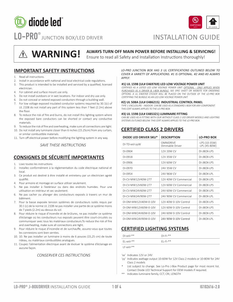
#1) UL 1598 (UL# E469769) LED LOW VOLTAGE POWER UNITCERTIFIED AS A LISTED LED LOW VOLTAGE POWER UNIT. OPTIONAL - ONLY APPLIES WHEN PURCHASED AS A DRIVER & J-BOX BUNDLE. SEE SPEC SHEET OR WEBSITE FOR ORDERING OPTIONS. A UL E469769 STICKER WILL BE PLACED ON THE OUTSIDE OF THE LO-PRO BOX CERTIFYING THE BUNDLE AS AN LED LOW VOLTAGE POWER UNIT.
IMPORTANT SAFETY INSTRUCTIONS1. Read all instructions. 2. Install in accordance with national and local electrical code regulations. 3. This product is intended to be installed and serviced by a qualified, licensed
electrician. 4. For cabinet and surface mount use only.5. Do not install outdoors or in wet locations. For indoor and dry use only. 6. Do not conceal or extend exposed conductors through a building wall.7. For low voltage exposed insulated conductor systems required by 30.1(c) of
UL 2108 do not install any part of this system less than 7 feet (2.2m) above the floor.
8. To reduce the risk of fire and burns, do not install this lighting system where the exposed bare conductors can be shorted or contact any conductive materials.
9. To reduce the risk of fire and overheating, make sure all connections are tight.10. Do not install any luminaire closer than 6 inches (15.25cm) from any curtain,
or similar combustible materials.11. Turn off electrical power before modifying the lighting system in any way.
SAVE THESE INSTRUCTIONS
CERTIFIED CLASS 2 DRIVERS
DO NOT CONNECT DIRECTLY TO HIGH VOLTAGE POWER!Read all warnings and installation instructions thoroughly.WARNINGWARNING! ALWAYS TURN OFF MAIN POWER BEFORE INSTALLING & SERVICING!
Ensure to read all Safety and Installation Instructions thoroughly!
Indicates 12V or 24VIndicates wattage output 10-60W for 12V Class 2 models or 10-80W for 24V Class 2 modelsList subject to change. See Lo-Pro J-Box Product page for most recent list. Contact Diode LED Technical Support for OEM models if required. Indicates luminaire family, CCT, CRI, LENGTH
LO-PRO JUNCTION BOX HAS 3 UL CERTIFICATIONS OUTLINED BELOW TO COVER A VARIETY OF APPLICATIONS. #1 IS OPTIONAL. #2 AND #3 ALWAYS APPLY:
#2) UL 508A (UL# E486215) INDUSTRIAL CONTROL PANEL TYPE 1 ENCLOSURE - INDOOR. CAN BE USED AS A STANDARD J-BOX FOR ANY COMPONENT. THIS CERT ALWAYS APPLIES TO THE LO-PRO BOX.
#3) UL 1598 (UL# E485321) LUMINAIRE FITTINGCAN BE USED AS A FITTING WITH OUR WITHOUT CLASS 2 LED DRIVER MODELS AND LIGHTING SYSTEMS OUTLINED BELOW. THIS CERT ALWAYS APPLIES TO THE LO-PRO BOX.
DIODE LED DRIVER SKU* DESCRIPTION LO-PRO BOX
DI-TD-xxV-yyW OMNIDRIVEDimmable Driver
-LPS (10-35W) -LPL (45-80W)
DI-0904 12V 20W CV DI-JBOX-LPS
DI-0918 12V 35W CV DI-JBOX-LPS
DI-0906 12V 60W CV DI-JBOX-LPS
DI-0970 24V 35W CV DI-JBOX-LPS
DI-0954 24V 96W CV DI-JBOX-LPL
DI-CV-MW12V40W-277 12V 40W CV Commercial DI-JBOX-LPS
DI-CV-MW12V60W-277 12V 60W CV Commercial DI-JBOX-LPS
DI-CV-MW24V60W-277 24V 60W CV Commercial DI-JBOX-LPS
DI-CV-MW24V90W-277 24V 90W CV Commercial DI-JBOX-LPL
DI-DM-MW12V40W-0-10V 12V 40W 0-10V Control DI-JBOX-LPS
DI-DM-MW12V60W-0-10V 12V 60W 0-10V Control DI-JBOX-LPS
DI-DM-MW24V60W-0-10V 24V 60W 0-10V Control DI-JBOX-LPS
DI-DM-MW24V90W-0-10V 24V 90W 0-10V Control DI-JBOX-LPL
‘xx’‘yy’
*
**
DI-xxV-** DI-FI-**
EL-xxV-** EL-FI-**
LF-xxV-**
CERTIFIED LIGHTING SYSTEMS
CONSIGNES DE SÉCURITÉ IMPORTANTES1. Lisez toutes les instructions2. Installez conformément à la réglementation du code électrique national et
local. 3. Ce produit est destiné à être installé et entretenu par un électricien agréé
qualifié.4. Pour armoire et montage en surface utilizer seulement.5. Ne pas installer à l’extérieur ou dans des endroits humides. Pour une
utilisation en intérieur et sec seulement.6. Ne pas cacher ou allonger des conducteurs exposés à travers un mur de
bâtiment.7. Pour la basse exposée tension systèmes de conducteurs isolés requis par
30.1 (c) de la norme UL 2108 ne pas installer une partie de ce système moins de 7 pieds (2.2m) au-dessus du sol.
8. Pour réduire le risque d’incendie et de brûlures, ne pas installer ce système d’éclairage où les conducteurs nus exposés peuvent être court-circuités ou communiquer avec tous les matériaux conducteurs.To reduce the risk of fire and overheating, make sure all connections are tight.
9. Pour réduire le risque d’incendie et de surchauffe, assurez-vous que toutes les connexions sont bien serrées.
10. 10. Ne pas installer un luminaire à moins de 6 pouces (15,25 cm) de toute rideau, ou matériaux combustibles analogues.
11. Coupez l’alimentation électrique avant de évoluer le système d’éclairage en aucune façon.
CONSERVER CES INSTRUCTIONS

2 OF 4 IG102616-2.0LO-PRO® J-BOX/DRIVER INSTALLATION GUIDE
SUPPLIED ACCESSORIES
INSTALLATION
A. Lo-Pro Junction Box (1)B. Driver Mounting Bracket (1)C. Ground Screw (1)D. Thumb Screws (2)E. Cover Screws (2)
F. Mounting Screws (4)G. Wire Connector 22-14AWG
(600V) (6)H. NM (Non-Metallic) Cable
Strain Relief (2) - 3/8”
A. B.
C. D.
Lo-Pro Junction Box (Small): DI-JBOX-LPS ORLo-Pro Junction Box (Large): DI-JBOX-LPL
E. F.
Power Supply/LED Driver Sold Separately.
1 TURN POWER OFF AT CIRCUIT BREAKER
2
SHOCK HAZARD! May result in serious injury or death.Turn power OFF at circuit breaker prior to installation.
DETERMINE LOCATION TO INSTALL COMPONENTS
1) Class 2 Driver& Lo Pro Box
2) Control 3) Fixture
Refer to SYSTEM DIAGRAM under step 7. Ensure to calculate LED load properly for loading LED driver. See LED luminaire installation guide for calculating loads.
WIRE GAUGE & VOLTAGE DROPEnsure applicable wire is installed between driver, fixture, and any controls in between. When choosing wire, factor in voltage drop, amperage rating, and type (in-wall rated, wet location rated, etc.)
G. H.
MOUNT BOX TO SURFACE WITH 4X SCREWS.
3 PUNCH OUT KNOCKOUTS FOR CONDUIT ACCESS
4 ATTACH INCLUDED 3/8” NM (NON-METTALIC)CABLE STRAIN RELIEF OR OTHER FITTING FOR CONDUIT ACCESS.Additional fittings for BX cable, flexible conduit and rigid conduit must be purchased at local hardware store.J-Box actual KO diameter is 0.87” and fits 3/8” fittings.
a. Use punch and hammer to loosen K/O. b. Grip K/O with pliers. Bend back and forth until broken off.
5
FASTEN POWER SUPPLY TO LO-PRO J-BOX.6
Mount J-Box to a sturdy surface in a position where it can be easily located and accessed for servicing and troubleshooting.
D (2)
F (4)
B (1)
H (2)

3 OF 4 IG102616-2.0LO-PRO® J-BOX/DRIVER INSTALLATION GUIDE
Grounding Screw*
Wire Combination Range Wire Combination Range (mm)
600V Max22 to 14 AWGMin. (1) #18 & (2) #20 Max. (2) # 14
600V Max0.34mm2 to 2.5mm2
Min. (1) 0.75mm2 w/ (1) 0.50mm2
Max. (4) 1.5mm2 w/ (1) 0.50mm2
1. GND*: Attach to J-Box and to Primary Ground2. Neutral: To Primary High Voltage Neutral3. Line (Hot): To Primary High Voltage Line Hot4. V+: To Low Voltage Load V+5. V−: To Low Voltage Load V−
WARNING! SYSTEM DIAGRAM NOTE!Each compatible LED driver has a unique System Diagram and color-coded wires. Please see each LED driver, luminaire (tape light, puck light, etc.), and control installation guide for System Diagrams, connections and wire colors. Pictured below is a Traditional ON/OFF Switching system. This is for reference only and does not apply to every driver.
Wire LED Driver. Ensure main power is OFF.
HIGH VOLTAGEAC INPUT
OUTPUT TO LOW VOLTAGE LED LOAD
Line (Hot)Neutral
GND
V+V─
WIRE DRIVER TO AC INPUT AND LOW VOLTAGE LOAD.7
INSTALLATION CONT.
LED Driver and J-Box must be grounded in accordance with local and national electrical codes. Ground the LED Driver and J-Box with the included Green Grounding Screw. Some compatible LED drivers are Class II certified and do not require a FG (Fault Ground Connection). Refer to the LED driver label and installation guide for more information.
*
3/8 in. (10 mm)
LN
G*NL V+
V−
120VAC On/Off Switch Class 2 LED Driver Installed in Lo-Pro J-Box
V+
V-
LED Tape Light / Fixture
Inst
all a
pplic
able
wire
gau
ge /
type
V+
V-
AC Power50/60Hz
INPU
T
OUT
PUT
TRADITIONAL ON/OFF SYSTEM DIAGRAM
C (1)
G (4-6)

4 OF 4
® Toll Free: 877.817.6028 | Fax: 415.592.1596 | www.DiodeLED.com | [email protected]© 2016 Elemental LED Inc. All rights reserved. Specifications are subject to change without notice.
IG102616-2.0LO-PRO® J-BOX/DRIVER INSTALLATION GUIDE
FINISH ASSEMBLY.8
a. Tighten Strain Relief.
b. Tuck Wires into compartments.
b. Fasten lid to Lo-Pro Junction Box.
INSTALLATION CONT.
9 TURN POWER ON AT CIRCUIT BREAKER.
SYSTEM WORKING IMPROPERLY?Turn power OFF at circuit breaker and verify all connections. Review SYSTEM DIAGRAMS and TROUBLESHOOTING on LED Driver, Luminaire, and Control Installation Guides, or call Diode LED Technical Support at 877.817.6028.
ADDITIONAL RESOURCESVisit the on-line product page at www.DiodeLED.com for full product specifications, installation guides, and warranty information.
LO-PRO JUNCTION BOX / LED DRIVER SPEC SHEETVOLTAGE DROP CHARTSLED DRIVER SPECIFICATION SHEETS / INSTALLATION GUIDESLED TAPE LIGHT OR LUMINAIRE SPECIFICATION SHEETS / INSTALLATION GUIDES
TROUBLESHOOTINGFor System Troubleshooting see individual LED Driver, Luminaire, and Control Installation Guides.
E (2)