WVR6100, WVR7000, and WVR7100 Waveform Rasterizers User ...
56
071-1991-01 www.tektronix.com WVR6100, WVR7000, and WVR7100 Waveform Rasterizers User Technical Reference
Transcript of WVR6100, WVR7000, and WVR7100 Waveform Rasterizers User ...

071-1991-01
www.tektronix.com
WVR6100, WVR7000, and WVR7100Waveform RasterizersUser Technical Reference

Copyright © Tektronix. All rights reserved. Licensed software products are owned by Tektronix or its subsidiaries or
suppliers, and are protected by national copyright laws and international treaty provisions.
Tektronix products are covered by U.S. and foreign patents, issued and pending. Information in this publication supercedes
that in all previously published material. Specifications and price change privileges reserved.
TEKTRONIX and TEK are registered trademarks of Tektronix, Inc.
Contacting Tektronix
Tektronix, Inc.
14200 SW Karl Braun Drive
P.O. Box 500
Beaverton, OR 97077
USA
For product information, sales, service, and technical support:
� In North America, call 1-800-833-9200.
� Worldwide, visit www.tektronix.com to find contacts in your area.
Warranty 2
Tektronix warrants that this product will be free from defects in materials and workmanship for a period of one (1)
year from the date of shipment. If any such product proves defective during this warranty period, Tektronix, at its
option, either will repair the defective product without charge for parts and labor, or will provide a replacement in
exchange for the defective product. Parts, modules and replacement products used by Tektronix for warranty work
may be new or reconditioned to like new performance. All replaced parts, modules and products become the
property of Tektronix.
In order to obtain service under this warranty, Customer must notify Tektronix of the defect before the expiration
of the warranty period and make suitable arrangements for the performance of service. Customer shall be
responsible for packaging and shipping the defective product to the service center designated by Tektronix, with
shipping charges prepaid. Tektronix shall pay for the return of the product to Customer if the shipment is to a
location within the country in which the Tektronix service center is located. Customer shall be responsible for
paying all shipping charges, duties, taxes, and any other charges for products returned to any other locations.
This warranty shall not apply to any defect, failure or damage caused by improper use or improper or inadequate
maintenance and care. Tektronix shall not be obligated to furnish service under this warranty a) to repair damage
resulting from attempts by personnel other than Tektronix representatives to install, repair or service the product;
b) to repair damage resulting from improper use or connection to incompatible equipment; c) to repair any
damage or malfunction caused by the use of non-Tektronix supplies; or d) to service a product that has been
modified or integrated with other products when the effect of such modification or integration increases the time
or difficulty of servicing the product.
THIS WARRANTY IS GIVEN BY TEKTRONIX WITH RESPECT TO THE PRODUCT IN LIEU OF ANY
OTHER WARRANTIES, EXPRESS OR IMPLIED. TEKTRONIX AND ITS VENDORS DISCLAIM ANY
IMPLIED WARRANTIES OF MERCHANTABILITY OR FITNESS FOR A PARTICULAR PURPOSE.
TEKTRONIX’ RESPONSIBILITY TO REPAIR OR REPLACE DEFECTIVE PRODUCTS IS THE SOLE AND
EXCLUSIVE REMEDY PROVIDED TO THE CUSTOMER FOR BREACH OF THIS WARRANTY.
TEKTRONIX AND ITS VENDORS WILL NOT BE LIABLE FOR ANY INDIRECT, SPECIAL, INCIDENTAL,
OR CONSEQUENTIAL DAMAGES IRRESPECTIVE OF WHETHER TEKTRONIX OR THE VENDOR HAS
ADVANCE NOTICE OF THE POSSIBILITY OF SUCH DAMAGES.


Table of Contents
WVR6100, WVR7000, and WVR7100 User Technical Reference i
Table of ContentsGeneral Safety Summary iii. . . . . . . . . . . . . . . . . . . . . . . . . . . . . . . . . . . . . . . . . . . . . . . . . . . . . . . . . . . . . . . . . . . . .
To Avoid Fire or Personal Injury iii. . . . . . . . . . . . . . . . . . . . . . . . . . . . . . . . . . . . . . . . . . . . . . . . . . . . . . . . . . . . .Symbols and Terms iv. . . . . . . . . . . . . . . . . . . . . . . . . . . . . . . . . . . . . . . . . . . . . . . . . . . . . . . . . . . . . . . . . . . . .
Preface v. . . . . . . . . . . . . . . . . . . . . . . . . . . . . . . . . . . . . . . . . . . . . . . . . . . . . . . . . . . . . . . . . . . . . . . . . . . . . . . . . .Related User Documents v. . . . . . . . . . . . . . . . . . . . . . . . . . . . . . . . . . . . . . . . . . . . . . . . . . . . . . . . . . . . . . . . . .Conventions Used in this Manual v. . . . . . . . . . . . . . . . . . . . . . . . . . . . . . . . . . . . . . . . . . . . . . . . . . . . . . . . . . . .
Installation Variations 1. . . . . . . . . . . . . . . . . . . . . . . . . . . . . . . . . . . . . . . . . . . . . . . . . . . . . . . . . . . . . . . . . . . . . . . .To Connect Directly to a PC 1. . . . . . . . . . . . . . . . . . . . . . . . . . . . . . . . . . . . . . . . . . . . . . . . . . . . . . . . . . . . . . . .To Connect to a Network 1. . . . . . . . . . . . . . . . . . . . . . . . . . . . . . . . . . . . . . . . . . . . . . . . . . . . . . . . . . . . . . . . . .Remote Communication 4. . . . . . . . . . . . . . . . . . . . . . . . . . . . . . . . . . . . . . . . . . . . . . . . . . . . . . . . . . . . . . . . . .
Using a Web Browser 4. . . . . . . . . . . . . . . . . . . . . . . . . . . . . . . . . . . . . . . . . . . . . . . . . . . . . . . . . . . . . . . .Using the Java Applet 5. . . . . . . . . . . . . . . . . . . . . . . . . . . . . . . . . . . . . . . . . . . . . . . . . . . . . . . . . . . . . . . .Using the WVR Remote Front Panel 10. . . . . . . . . . . . . . . . . . . . . . . . . . . . . . . . . . . . . . . . . . . . . . . . . . . . . .
Incoming Inspection 11. . . . . . . . . . . . . . . . . . . . . . . . . . . . . . . . . . . . . . . . . . . . . . . . . . . . . . . . . . . . . . . . . . . . .Basic Turn On and Self Test 11. . . . . . . . . . . . . . . . . . . . . . . . . . . . . . . . . . . . . . . . . . . . . . . . . . . . . . . . . . . .Front Panel Test 12. . . . . . . . . . . . . . . . . . . . . . . . . . . . . . . . . . . . . . . . . . . . . . . . . . . . . . . . . . . . . . . . . . . .XGA and Extended Diagnostics Test 13. . . . . . . . . . . . . . . . . . . . . . . . . . . . . . . . . . . . . . . . . . . . . . . . . . . . . .Fan Test 14. . . . . . . . . . . . . . . . . . . . . . . . . . . . . . . . . . . . . . . . . . . . . . . . . . . . . . . . . . . . . . . . . . . . . . . . . .
Display Information 15. . . . . . . . . . . . . . . . . . . . . . . . . . . . . . . . . . . . . . . . . . . . . . . . . . . . . . . . . . . . . . . . . . . . . . . . .Waveform Display 15. . . . . . . . . . . . . . . . . . . . . . . . . . . . . . . . . . . . . . . . . . . . . . . . . . . . . . . . . . . . . . . . . . . . . . .Vector Display 17. . . . . . . . . . . . . . . . . . . . . . . . . . . . . . . . . . . . . . . . . . . . . . . . . . . . . . . . . . . . . . . . . . . . . . . . .Timing Display 18. . . . . . . . . . . . . . . . . . . . . . . . . . . . . . . . . . . . . . . . . . . . . . . . . . . . . . . . . . . . . . . . . . . . . . . . .Picture Display 20. . . . . . . . . . . . . . . . . . . . . . . . . . . . . . . . . . . . . . . . . . . . . . . . . . . . . . . . . . . . . . . . . . . . . . . . .Audio Display 22. . . . . . . . . . . . . . . . . . . . . . . . . . . . . . . . . . . . . . . . . . . . . . . . . . . . . . . . . . . . . . . . . . . . . . . . . .LTC Waveform Display 26. . . . . . . . . . . . . . . . . . . . . . . . . . . . . . . . . . . . . . . . . . . . . . . . . . . . . . . . . . . . . . . . . . .Gamut Display 27. . . . . . . . . . . . . . . . . . . . . . . . . . . . . . . . . . . . . . . . . . . . . . . . . . . . . . . . . . . . . . . . . . . . . . . . .Status Display 28. . . . . . . . . . . . . . . . . . . . . . . . . . . . . . . . . . . . . . . . . . . . . . . . . . . . . . . . . . . . . . . . . . . . . . . . .Eye Display 30. . . . . . . . . . . . . . . . . . . . . . . . . . . . . . . . . . . . . . . . . . . . . . . . . . . . . . . . . . . . . . . . . . . . . . . . . . .Jitter Display 31. . . . . . . . . . . . . . . . . . . . . . . . . . . . . . . . . . . . . . . . . . . . . . . . . . . . . . . . . . . . . . . . . . . . . . . . . .
Supplemental Operating Information 33. . . . . . . . . . . . . . . . . . . . . . . . . . . . . . . . . . . . . . . . . . . . . . . . . . . . . . . . . . . . .Cloning Setups (Presets) 33. . . . . . . . . . . . . . . . . . . . . . . . . . . . . . . . . . . . . . . . . . . . . . . . . . . . . . . . . . . . . . . . . .
Using a Web Browser, Java Applet, or Java Application 33. . . . . . . . . . . . . . . . . . . . . . . . . . . . . . . . . . . . . . . .From a Web Browser 33. . . . . . . . . . . . . . . . . . . . . . . . . . . . . . . . . . . . . . . . . . . . . . . . . . . . . . . . . . . . . . . . .From the Java Application 34. . . . . . . . . . . . . . . . . . . . . . . . . . . . . . . . . . . . . . . . . . . . . . . . . . . . . . . . . . . . .
Upgrading the Waveform Rasterizer Firmware 38. . . . . . . . . . . . . . . . . . . . . . . . . . . . . . . . . . . . . . . . . . . . . . . . . .PC System Requirements 38. . . . . . . . . . . . . . . . . . . . . . . . . . . . . . . . . . . . . . . . . . . . . . . . . . . . . . . . . . . . .Before You Begin 39. . . . . . . . . . . . . . . . . . . . . . . . . . . . . . . . . . . . . . . . . . . . . . . . . . . . . . . . . . . . . . . . . . . .Installing the Firmware 40. . . . . . . . . . . . . . . . . . . . . . . . . . . . . . . . . . . . . . . . . . . . . . . . . . . . . . . . . . . . . . . .Upgrading Multiple Instruments 42. . . . . . . . . . . . . . . . . . . . . . . . . . . . . . . . . . . . . . . . . . . . . . . . . . . . . . . . . .Verifying the Upgrade 43. . . . . . . . . . . . . . . . . . . . . . . . . . . . . . . . . . . . . . . . . . . . . . . . . . . . . . . . . . . . . . . . .
Description of Cable Types 43. . . . . . . . . . . . . . . . . . . . . . . . . . . . . . . . . . . . . . . . . . . . . . . . . . . . . . . . . . . . . . . .
Index 45. . . . . . . . . . . . . . . . . . . . . . . . . . . . . . . . . . . . . . . . . . . . . . . . . . . . . . . . . . . . . . . . . . . . . . . . . . . . . . . . . . .

Table of Contents
ii WVR6100, WVR7000, and WVR7100 User Technical Reference
General Safety Summary
WVR6100, WVR7000, and WVR7100 User Technical Reference iii
General Safety SummaryReview the following safety precautions to avoid injury and prevent damage to this product or any products connected to it.
To avoid potential hazards, use this product only as specified.
Only qualified personnel should perform service procedures.
To Avoid Fire or Personal Injury
Use Proper Power Cord. Use only the power cord specified for this product and certified for the country of use.
Connect and Disconnect Properly. Connect the probe output to the measurement instrument before connecting theprobe to the circuit under test. Disconnect the probe input and the probe ground from the circuit under test beforedisconnecting the probe from the measurement instrument.
Ground the Product. This product is grounded through the grounding conductor of the power cord. To avoid electricshock, the grounding conductor must be connected to earth ground. Before making connections to the input or output
terminals of the product, ensure that the product is properly grounded.
Observe All Terminal Ratings. To avoid fire or shock hazard, observe all ratings and markings on the product. Consultthe product manual for further ratings information before making connections to the product.
Do not apply a potential to any terminal, including the common terminal, that exceeds the maximum rating of that terminal.
Power Disconnect. The power cord disconnects the product from the power source. Do not block the power cord; itmust remain accessible to the user at all times.
Do Not Operate Without Covers. Do not operate this product with covers or panels removed.
Use Proper Fuse. Use only the fuse type and rating specified for this product.
Avoid Exposed Circuitry. Do not touch exposed connections and components when power is present.
Do Not Operate With Suspected Failures. If you suspect there is damage to this product, have it inspected byqualified service personnel.
Do Not Operate in Wet/Damp Conditions.
Do Note Operate in an Explosive Atmosphere.
Keep Product Surfaces Clean and Dry.
Provide Proper Ventilation. Refer to the manual’s installation instructions for details on installing the product so it hasproper ventilation.
General Safety Summary
iv WVR6100, WVR7000, and WVR7100 User Technical Reference
Symbols and Terms
Terms in this Manual. These terms may appear in this manual:
WARNING. Warning statements identify conditions or practices that could result in injury or loss of life.
CAUTION. Caution statements identify conditions or practices that could result in damage to this product or other property.
Terms on the Product. These terms may appear on the product:
DANGER indicates an injury hazard immediately accessible as you read the marking.
WARNING indicates an injury hazard not immediately accessible as you read the marking.
CAUTION indicates a hazard to property including the product.
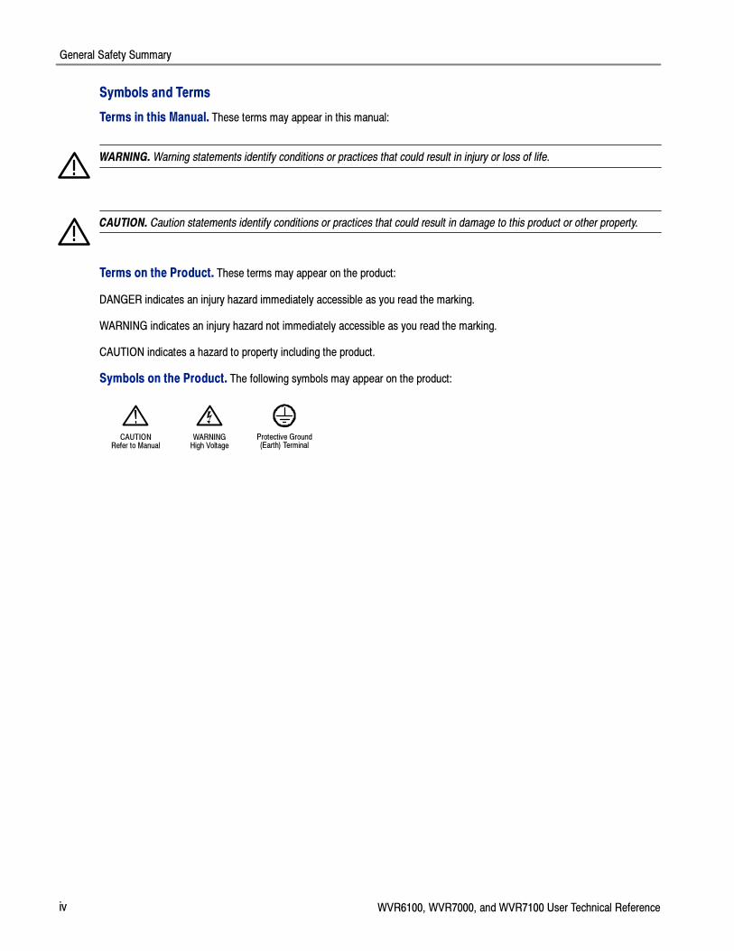
Symbols on the Product. The following symbols may appear on the product:
CAUTIONRefer to Manual
WARNINGHigh Voltage
Protective Ground(Earth) Terminal

Preface
WVR6100, WVR7000, and WVR7100 User Technical Reference v
PrefaceThis manual contains user reference information that supplements the information in theWVR6100, WVR7000, and
WVR7100 Quick Start User Manual.
NOTE. If you have a WVR7100 or WVR6100 waveform rasterizer with system software verion 1, this manual does not
apply. Use the documentation that shipped with your instrument. If your WVR6100 or WVR7100 has system software
version 2 and later, use this manual. This manual also applies if you have upgraded from an older software version to the
new software with a new audio option, or have upgraded to the new software with no audio option installed.
Related User Documents
Item Purpose Location
WVR6100, WVR7000, and
WVR7100 Waveform Rasterizers
Quick Start User Manual
Installation and high-level overviewof instrument operation +
WWW.Tektronix.com
+
WVR6100, WVR7000, and
WVR7100 Waveform Rasterizers
User Technical Reference
(this manual)
In-depth descriptions of instrumentoperation
WWW.Tektronix.com+
Online Help In-depth instrument operation andUI help
WVR6100, WVR7000, and
WVR7100 Specifications and
Performance Verification Technical
Reference
Specifications and procedure forchecking instrument performance
WWW.Tektronix.com+
WVR & WFM Series ManagementInformation Base (MIB) Reference
SNMP command reference forremotely controlling the instrument
WWW.Tektronix.com
+ +
Instrument webpage
‘
WVR6100, WVR7000, and
WVR7100 Waveform Rasterizers
Service Manual
Optional manual supporting module-level servicing of the instrument
Conventions Used in this Manual
The following icons are used throughout this manual:
SequenceStep
Connectpower
Network XGA
1

Preface
vi WVR6100, WVR7000, and WVR7100 User Technical Reference

Installation Variations
WVR6100, WVR7000, and WVR7100 User Technical Reference 1
Installation VariationsSee yourWVR6100, WVR7000, and WVR7100 Quick Start User Manual for basic installation instructions; see the
following information for other installation situations and for remote communication instructions, an optional procedure thatis suitable for incoming inspection of this product.
To Connect Directly to a PC
The waveform rasterizer is often connected to a PC, as follows:
1. Connect your waveform rasterizer to aPC through an ethernet hub, as shown.
A standard crossover cable can be
substituted for the hub.
2. Set up the waveform rasterizer as de-
scribed in steps 1 through 6 onpage 2, choosing Manual IP mode
and setting the IP address manually.
Be sure to set an address that is com-patible with the setting of your PC.
3. SNMP setup, if used, is the same as
described under SNMP Setup onpage 3.
WVR6100 ,WVR7000, orWVR7100
Laptop PC
192.168.1.2
HUB
Ethernetconnection
Ethernetconnection
Ethernet (locatedon rear panel)
IP address(192.168.1.1)
IP address(192.168.1.2)
1
UpLink -- noconnection
To Connect to a Network
The following topics cover configuring the IP settings, so that you can use the waveform rasterizer over a network, andconfiguring SNMP, which is required if you are using commands to control the waveform rasterizer.
Connection and IP Settings
To allow network access to the instrument, you need set the IP address. Network addresses can be assigned either
automatically or manually. If your network does not use DHCP, you will have to manually enter the address for the
instrument. To get an address, talk to your LAN administrator.

Installation Variations
2 WVR6100, WVR7000, and WVR7100 User Technical Reference
To connect your waveform rasterizer to anetwork and access it with a remote PC,
set up the rasterizer as described in the
steps that follow.
NOTE. You may want to connect directly
between your PC and the instrument. See
To Connect Directly to a PC on page 1.
WVR6100, WVR7000,or WVR7100
Lap Top PC
192.168.1.2
Network
Ethernet (locatedon rear panel)
IP address(192.168.1.1)
IP address(192.168.1.2)
1. Press CONFIG to display the Configu-ration menu.
2. Select Network Settings > Web En-
able. Press SEL to select On.
3. Set the IP Config Mode to Manual or
DHCP, depending on your network set-up.
4. If you cannot use DHCP, set the sub-
net mask and gateway address net-work parameters in this menu; see
your LAN administrator for required
values. (Be sure to use compatible ad-dresses between the PC and the ras-
terizer.) You can also set the instru-
ment name and view the MAC Ad-dress.
5. If the password is set, note it. You will
be prompted for it when you connect tothe rasterizer.
NOTE. For help with entering or
changing the password, select Web
Password, and press the HELP button.
6. Press CONFIG to close the Configura-tion menu.
3
4
2
5
1 6

Installation Variations
WVR6100, WVR7000, and WVR7100 User Technical Reference 3
SNMP Setup
If you intend to use SNMP commands to control the instrument (SNMP control is primarily intended for access through
automation systems), you need to set up SNMP parameters.
NOTE. The WFM Series Waveform Monitors wfm_mon.mib and the WVR7100.mib can be downloaded from the
instrument Web page. See step 10 on page 5 in this manual.
The procedure to set SNMP settings is similar to that shown on page 2 for IP settings; the parameters that can be set
follow:
SNMP Enable This entry in the Network Settings portion of the Configuration menu allows you to turnon or off the remote access through SNMP.
SNMP Trap Enable This menu entry allows you to turn on or off the traps that are sent out through SNMP.
SNMP Trap Address This menu entry allows you to set IP addresses to which SNMP traps are sent throughSNMP. Traps can be sent to up to four addresses when error conditions are detected.
NOTE. A value of all zeroes for the address will disable that trap output.
Private Community String This menu entry allows you to set the Private Community string. This string is effectivelya password. Without this string, SNMP commands cannot change values in the
instrument.
NOTE. The Private String is necessary for SNMP access to write changes into the
instrument.
Public Community String This menu entry allows you to set the Public Community string. This string is effectively apassword. Without this string, SNMP commands cannot read values from the instrument.
NOTE. The Public String is necessary for SNMP access to read values from the instrument.

Installation Variations
4 WVR6100, WVR7000, and WVR7100 User Technical Reference
Remote Communication
The following topics cover remote communications that occur:
� Over an Ethernet network through a Web browser
� Over an Ethernet network through a Java applet
� Over a cable using the optional remote front panel
Using a Web Browser
You can use a Web browser to access the waveform rasterizer and save screen captures, download presets, anddownload the error log. Your rasterizer does need to be connected to an IP network via Ethernet. You will need to set the
IP Config Mode, IP Address, Subnet Mask, and possibly the Gateway Address, to meet your network configurationrequirements.
To connect to the waveform rasterizer using a Web browser, do the following:
1. Press CONFIG to display the Configu-ration menu.
2. Select Network Settings > Web En-
able. Press SEL to select On.
3. Set the IP Config Mode to Manual or
DHCP, depending in your network set-up.
4. Note the IP Address for use in step 6.
NOTE. You may have to set other
network parameters in this menu; see
your LAN administrator if required.
5. Press CONFIG to close the Configura-tion menu.
1
3
4
25

Installation Variations
WVR6100, WVR7000, and WVR7100 User Technical Reference 5
6. Start your Web browser and type thenetwork address of the waveform ras-
terizer (from step 4) into the URL entry
box like this:1
����������������6
Click on the indicated items to:
1. Start the Java applet (see next proce-
dure).
2. Display a list of Web clients (by net-work address) currently logged into the
waveform rasterizer.
3. Display which options this instrument
is equipped with.
4. Display waveform rasterizer onlinehelp.
5. Capture the full or status bar displays
in BMP or PNG formats. Retrieves thecapture for saving to a file.
6. Download and display the Error Log as
tab-delimited text or an HTML table.
7. Download and display the Diagnostic
Log as tab-delimited text or an HTML
table.
8. Download instrument settings to a file
in binary format.
9. Download Preset <N> to a file in binary
format, where <N> is any number from
1 to 5.
10. Download each of the MIB files in
ASCII format.
2
1
4
5
3
7
8
9
10
6
1 Many Web browsers do not correctly interpret IP addresses with leading zeros. If the IP address shown in theConfiguration menu contains leading zeros as in 124.161.038.151, remove the “0” when entering it into the addressline of the browser. For example, 124.161.038.151 should be entered as 124.161.38.151.
Using the Java Applet
To further extend your control from a remote PC, launch the Java applet from the Web browser to change the waveform
rasterizer settings, display and refresh the waveform rasterizer screen, save screen captures, download and uploadpresets, and download the error log. The Java applet provides a menu bar and a virtual front panel that gives you complete
remote control over instrument settings.

Installation Variations
6 WVR6100, WVR7000, and WVR7100 User Technical Reference
Note that the Web interface operation is optimized for screen resolutions of 1024 x 768 or higher. Operation on computerswith lower resolution requires scroll-bar use to see the entire interface.
Java Applet Requirements
If you install Java on your PC, you can launch a Java applet to control the waveform rasterizer. The Java Applet requires:
� Version 1.4.1 (or later) of the Java Run-Time Environment (JRE) from Sun Microsystems installed on your PC. To
download the JRE (Java Run-Time Environment) plug-in from Sun Microsystems, download the appropriate code fromthe Sun Microsystems URL: http://java.sun.com/j2se/1.4/
Once you download the executable file, launch the installation software and follow the instructions.
� Microsoft Internet Explorer 5.0 or later running on a Windows PC
� Netscape on Apple Linux or on UNIX machines
NOTE. If you need remote operation on other platforms, use the Java Application, which is a stand-alone application that
provides all of the features of the Java applet. The Java Application can be run on any platform that supports Java version
1.4.1 or later, including Windows NT/2000/XP, Linux, Unix, and Mac OS X. The Java application, unlike the Java applet,
does not run within a Web browser and, thus, is not subject to the various browser limitations. You can download the Java
application package from the Tektronix Web site. Look forWVR Remote Software Package in the download section of theVideo Test Product pages.
The Java Application can be used to download instrument presets to a remote file and upload from the remote file to the
instrument.
Launching the Applet
When you launch the Java applet, it is downloaded from the waveform rasterizer and launched. There is no software
installation required to use the applet (other than the Java Run-Time Environment noted previously). The waveformrasterizer supports up to three remote clients (screen updates become slower with each client added).
1. Launch the Web browser as describedunder Using a Web Browser, starting
on page 4.
2. Once the Remote Interface appears,select Launch Applet. and the Java
applet will be launched.
2

Installation Variations
WVR6100, WVR7000, and WVR7100 User Technical Reference 7
3. Use the menu bar of the Java appletwindow to quickly access functions
that are not available from the front
panel. Also, access the Configurationmenu by using these menus rather
than a front-panel button.
4. For front panel functions, click the
virtual front-panel controls to remotely
press most instrument front panel con-trols.
5. Read the status bar the same way as
you would when it is displayed directlyfrom the instrument display. (See To
Determine Status At-A-Glance in the
WVR6100, WVR7000, and WVR7100
Quick Start User Manual.
3
5
4
Selecting Displays
1. To turn the display of the virtual front
panel on or off, click View > Control
Panel.
2. To turn the display of the Waveform
Display Window on or off, click View >Waveform Display.
NOTE. The displays can be turned on
or off independently of each other.
Here they are both displayed in the
applet window.
21Waveformdisplay
Controlpanel
Installation Variations
8 WVR6100, WVR7000, and WVR7100 User Technical Reference
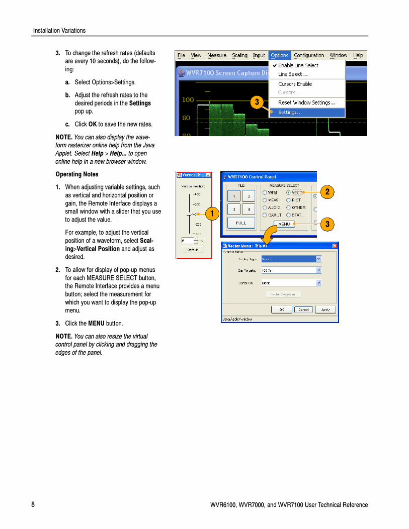
3. To change the refresh rates (defaultsare every 10 seconds), do the follow-
ing:
a. Select Options>Settings.
b. Adjust the refresh rates to the
desired periods in the Settingspop up.
c. Click OK to save the new rates.
NOTE. You can also display the wave-
form rasterizer online help from the Java
Applet. Select Help > Help... to open
online help in a new browser window.
3
Operating Notes
1. When adjusting variable settings, such
as vertical and horizontal position or
gain, the Remote Interface displays asmall window with a slider that you use
to adjust the value.
For example, to adjust the vertical
position of a waveform, select Scal-
ing>Vertical Position and adjust asdesired.
2. To allow for display of pop-up menus
for each MEASURE SELECT button,the Remote Interface provides a menu
button; select the measurement for
which you want to display the pop-upmenu.
3. Click the MENU button.
NOTE. You can also resize the virtual
control panel by clicking and dragging the
edges of the panel.
1
3
2

Installation Variations
WVR6100, WVR7000, and WVR7100 User Technical Reference 9
Usage Notes
The Remote Interface Control Panel differs from the instrument front panel in that it provides a menu. The menu provides
many controls, some of which duplicate functions that are directly available from the control panel. See the list that follows.
Menu Commands Description
File Restore Settings Restores instrument-stored setup that you select (one of Preset 1through Preset 5 or Factory) to the waveform rasterizer
Save as Preset Saves the current waveform rasterizer settings as as setup in theinstrument (select any one of Preset 1 through Preset 5)
Load Presets From File This selection is disabled in the Java Applet. In the JavaApplication (see NOTE on page 6), this selection restores the
presets (1 through 5) to the waveform rasterizer from any
previously saved presets file that you select
Save Presets To File This selection is disabled in the Java Applet. In the JavaApplication (see NOTE on page 6), this selection saves the
waveform rasterizer presets 1 through 5 in a remote file
Exit Closes the Java applet
View Active Tile Changes the active tile
Full Screen Changes display to Full screen mode
Freeze... Captures the current image for most of the possible displays in thewaveform rasterizer
Control Panel Toggles the display of the control panel window on and off
Screen Capture Display Toggles the Waveform Display window on and off
Refresh Updates the Waveform Display
Measure Various control items Contents of this menu vary with the selection in the waveformrasterizer control panel (WFM, MEAS, AUDIO, GAMUT, VECT,
PICT, OTHER, or STATUS)
Scaling Vertical Position Displays a window to enable you to adjust the vertical position
Horizontal Position Displays a window to enable you to adjust the horizontal position
Gain Enables you to set the Gain to 1X, 5X, or set the variable gain
Sweep Enables you to set the sweep mode to One Line, Two Line, OneField, or Two Field
Mag Magnifies the Active Tile sweep rate
Input Inputs and Reference The settings displayed below Input correspond to the controls inthe Inputs and Ref groupings on the control panel
Options Line Select & Cursorscommands
These menu entries below Options duplicate operation of the LineSelect and Cursors controls on the control panel
Refresh Rate Specifies how often the Waveform Display should be automaticallyupdated
Configuration Various controls not avail-able on the front panel
The menu entries below Configuration duplicate most of thesetups available by display the Configuration menu using the
CONFIG button on the instrument front panel

Installation Variations
10 WVR6100, WVR7000, and WVR7100 User Technical Reference
Menu DescriptionCommands
Window Control Panel Moves the control panel window to the front if it is covered by theWaveform Display
Waveform Display Moves the Waveform Display window to the front if it is covered bythe control panel
Help Help Displays the waveform rasterizer online help
About Displays version information about the Java applet
Using the WVR Remote Front Panel
The WVR Remote Front Panel (RFP) is available to permit remote control of the waveform rasterizer. The WVR RFPworks with the main front panel and connects to the rasterizer through a cable. This cable may be up to 100 ft. long (a 25
ft. cable ships with the WVR RFP).
� To configure the WVR RFP, follow the installation instructions that ship with the WVR RFP product.
� To use the RFP module, use it as you would the integral front panel of an instrument. All operating procedures in thismanual and the instrument online help apply to operation from the WVR RFP as well as the integral front panel.
� If you have an instrument with firmware version 2.0 or greater, the local and remote FP are simultaneously active.
NOTE. If you have an early instrument that does not have a dedicated front panel button EYE button and have that
instrument upgraded with an Eye option, both the EYE Display and the Timing Display will be accessed under the MEAS
button. To view the EYE Display with such an instrument, press and hold the MEAS button and select Display Type>Eye
Display. With the EYE Display selected, the display and MEAS pop-up menu behave as described below. Selection of the
Timing Display and pop-up menu are described under Timing Display on page 18. If you use an RFP without an Eye
button, but the local instrument has an Eye button, the instrument will use the oldest FP version. Pressing the Eye button
on the local FP when you first install an RFP lets the instrument know that Eye is present on the RFP.
Cable Description
The requirements for cables that can be used with this WVRRFP module follow:
� Connectors (each end): 9-pin D-SUB, male, with jackscrews
� Cable: nine conductors, 26 gauge or heavier, shielded
� Construction: Pins 1--9 of each connector wired to corresponding pins of the alternate connector (connect pin 1 to
pin 1, and so on). Shield or drain wire bonded to metal shell at each end.
� Maximum length: 100 ft

Installation Variations
WVR6100, WVR7000, and WVR7100 User Technical Reference 11
Incoming Inspection
At your option, you can complete the following incoming inspection procedures. These procedures require no equipmentexcept a display to check functionality.
For the performance verification procedures, see theWVR6100, WVR7000, and WVR7100 Performance Verification and
Specification Technical Reference document on the Documents CD that shipped with this instrument.
Basic Turn On and Self Test
1. Connect an XGA monitor to the wave-form rasterizer.
2. Connect the AC power cord to the rear
of the instrument and to a 100 to240 VAC source. There is no power
switch on the waveform rasterizer, sothe instrument will turn on as soon as
you apply power.
Waveform Rasterizer(rear panel)Monitor
12
3. Look at the front panel immediately af-ter you apply power. All the buttons,
the text over the three knobs, and the
the Fault indicator should all light up.
After a couple of seconds, the lights in
the buttons and text will turn off.
After about 15 seconds, the fault light
should turn off.
Also after about 15 seconds, thePower on diagnostic page should
appear on the monitor.
Fault indicator lights
Text lights
4. Verify that the instrument passes allself tests. Any failures will be shown in
Red. The results of the Power on diag-
nostics are erased from the screen, butyou can view them by selecting
CONFIG > Utilities > View Diagnos-
tics Log.
5. After the diagnostics are finished, the
instrument state will be restored. Whenthe progress indicator in the lower-right
part of the screen is finished, the in-
strument has finished initializing.
4

Installation Variations
12 WVR6100, WVR7000, and WVR7100 User Technical Reference
Front Panel Test
1. Press FACTORY to restore the factorypreset. Wait for the process to com-
plete as indicated by the progress indi-
cator.
2. Press FULL to make the active tile be
full screen.
3. Press HELP to display the help
screens.
4. Press all the other buttons.
Each one should flash as you press it.
Most buttons bring up help text for that
button in the help screen. (Somebuttons, such as the presets, bring up
the same information.) The HELP and
the four arrow and the SEL keys do notbring up help text because they
traverse the help panes and content.
2
1 3
5. Press the right arrow key until the HelpContents pane in the upper-left corner
is highlighted.
6. Turn the GENERAL knob and verifythe selector box moves up and down
the list.
7. Press HELP to exit help.
7
5 6

Installation Variations
WVR6100, WVR7000, and WVR7100 User Technical Reference 13
XGA and Extended Diagnostics Test
NOTE. Where the following procedure says to press an arrow key, you can use the general knob on the front-panel if you
prefer.
1. Press CONFIG to display the CONFIGmenu.
2. Select Utilities, and then press SEL.
3. Select CPU Color Palette Check, andthen press SEL.
4. Verify that 16 distinct colors are dis-played. This tests the XGA data path
from the CPU.
1
4
2
3
5. Use the down arrow key to navigate toRun Advanced Diagnostics and then
press SEL.
6. Use the right-arrow key to highlight theContinue box and then press SEL to
run the test.
7. Verify that the XGA DAC is working by
looking at the White and Red ramps at
the top of the screen, and at the Greenand Blue ramps at the bottom of the
screen. They should not have steps
but should instead have a smooth tran-sition from dark to light.
5
6

Installation Variations
14 WVR6100, WVR7000, and WVR7100 User Technical Reference
8. Verify that the frequencies shown arewithin 10 kHz, and that rates shown
are within 0.1 µs, of the nominal val-
ues listed at right.
9. Verify that all the tests in the middle
section of the screen have a greenPass status.
� QDR Clock = 25.174 MHz
� VGA clock = 64.480 MHz
� Audio PLL1 = 12.288 MHz
� Audio PLL2 = 12.288 MHz
� Hsync rate : Width = 0.9 µs
� Vsync rate : Width = 26.5 µs
10. Verify that the bus bit activity tests(labeled Channel A:, Processor Video:,
and Composite Video:, and appearing
at the bottom of the screen) are as fol-lows:
� All three tests show both a red anda green bar in each bit location.
� The Processors Video test shows
8 bits from the CPU, a space, thenHsync, a space, Vsync, a space
and then the blank line. It is normal
for the V sync bit to blinkoccasionally.
11. Press SEL or cycle the power to
re-boot the unit for normal operation.
Fan Test
If the fault light in the lower left corner of the front panel is not on (Red), the fans are running. You should also be able to
hear them and feel air coming out the back of the instrument. At low temperatures, the fans will turn slowly and be veryquiet.

Display Information
WVR6100, WVR7000, and WVR7100 User Technical Reference 15
Display InformationThis section describes waveform rasterizer displays and the pop-up menus for controlling those displays.
NOTE. All pop-up menus are displayed by pressing the specified button for three seconds. To hide a pop-up menu, press
the specified button again.
Waveform Display
The WFM button displays the Waveform (WFM) display, which is the voltage versus time display used to view a waveform.
You can view the input signal in line or field sweep. You can choose which SDI signal elements are displayed (RGB,YRGB, or YPbPr), and you can apply filters to the signal. You can also display an SDI input as though it were a composite
signal. You can also control (in the CONFIG menu) whether EAV, SAV, and ANC data is included in the display.
Waveform Display Elements:
1. Is blank when vertical gain is X1;otherwise indicates that V Gain is x5 or
variable.
2. Lists the currently displayed waveformcolor-space. Dashes (----) indicate com-
ponents not displayed.
3. Lists the currently selected field andline (when in Line Select mode).
4. Lists the current sweep rate for tile.
5. Lists the Mag rate if MAG is on.1 2 3 4 5
Waveform Pop-up menu and settings
The Waveform pop-up menu enables you to choose the display style and display mode used in the active tile (SDI inputs
only), select a filter to apply to the input signal, or center the waveform in the display.
To choose a display mode, select from the following the choices (only available while displaying SDI inputs) in the menu:
� YPbPr -- Displays the input as Luma (Y) and color difference (Pb, Pr) components.
� YRGB -- Displays the input as Luma (Y), Red (R), Green (G), and Blue (B) components.
� RGB -- Displays the input as Red (R), Green (G), and Blue (B) components.
� SDI > Composite -- Displays the SDI input as if it has been encoded into composite. The sync and burst in this mode
are synthetic and convey no information about signal quality.
When viewing 525-line SDI input as a composite waveform while using line select mode, both burst phases may appear
when you would expect to see only one. This is because the line selection in SDI Mode is an odd/even selection, and
composite signals are normally viewed with a one-of-four or one-of-eight line selection.

Display Information
16 WVR6100, WVR7000, and WVR7100 User Technical Reference
To choose how the signal components are displayed in the active tile, use the Display Style menu setting (SDI inputs only)to select:
� Parade style -- has all the components shown one beside the other.
� Overlay style -- has all the components drawn at the same location so that they appear one on top of the other.
The Waveform pop-up menu Filter selection allows you to select filters to be applied to the video. This is useful for
isolating a specific characteristic of the input. For example, to measure amplitude, you may want to use a Luma or Low
pass filter to remove the high frequency components.
To choose a filter select one of the following filters from the Waveform menu:
� Flat -- Display with the full available bandwidth.
� Luma or Low Pass-- Display only the low-frequency portion of the signal.
� Chroma -- Display only the portion of the signal with frequencies near the color sub-carrier. For Composite inputs only.
� Flat + Luma-- A combination of a Flat and a Luma waveform from a Composite input; it shows two waveforms in
parade configuration.
NOTE. For SDI displays, such as RGB mode, the available filters are Flat and Low Pass. For Composite displays, the
available filters are Flat, Luma, Chroma, and Flat+Luma.
To cancel any horizontal or vertical position adjustments and restore the trace to the default position, select Center
Waveform and press SEL. For a tile in WFM mode, this puts the baseline at the zero graticule.

Display Information
WVR6100, WVR7000, and WVR7100 User Technical Reference 17
Vector Display
The VECT button calls up the Vector and Lightning displays, which provide for selection between two plots of the colorportions of the signal.
Lightning Display Elements:
1. Line. Pressing the LINE button setsthe horizontal gain to 1X.
2. Field. Pressing the FIELD button sets
the horizontal gain to 5X.
3. Mag. Pressing the MAG button en-
ables you to adjust the horizontal gain
using the GENERAL knob.
Lightning & Vector Display Elements:
4. Display Type. The selected display,
either Lightning or Vector.
5. Bar Target Setting. The bar target set-ting, either 75% or 100%.
6. Phase. Appears in Composite Vector
inputs only.
5
1
2
3
4
6
Vector Pop-up Menu
The Vector pop-up menu enables you to specify the display type and display mode (SDI inputs only), to set the bar targets,and to center the waveform in the display.
To choose the display type (SDI inputs only), use the pop-up menu to choose either:
� Vector -- The Vector display shows a plot of the R-Y signal on the vertical axis and the B-Y signal on the horizontalaxis. This display is useful for looking at hue and saturation of the colors, but does not show luminance information.
� Lightning -- The Lightning display shows the same color signals as in vector, but they are plotted versus luminance.One color difference signal is plotted in the top half and the other in the bottom. Lightning is useful for checking
chroma and luma gain, and for checking chroma to luma delay using the timing marks that show errors in the green to
magenta transition on a color bar signal. This is a Tektronix proprietary display and is for SDI signals only.
To select which scaling should be used in the active tile for either the Vector or Lighting display, use the menu to select
75% or 100% scaling.
To cancel any horizontal or vertical position adjustments and restore the trace to the default position, use the up/down
arrow keys to select Center Waveform in the menu. Then:
� For a Lightning display, press SEL to center the waveform. The trace is set back to the center of the tile.
� For a Vector display, press the right-arrow key to select the color you want to locate at the center of the display.
� For additional vector graticule options, see Configuration/Graticule vector, I/Q axis, and Vector Compass Rose in themenu.
Display Information
18 WVR6100, WVR7000, and WVR7100 User Technical Reference
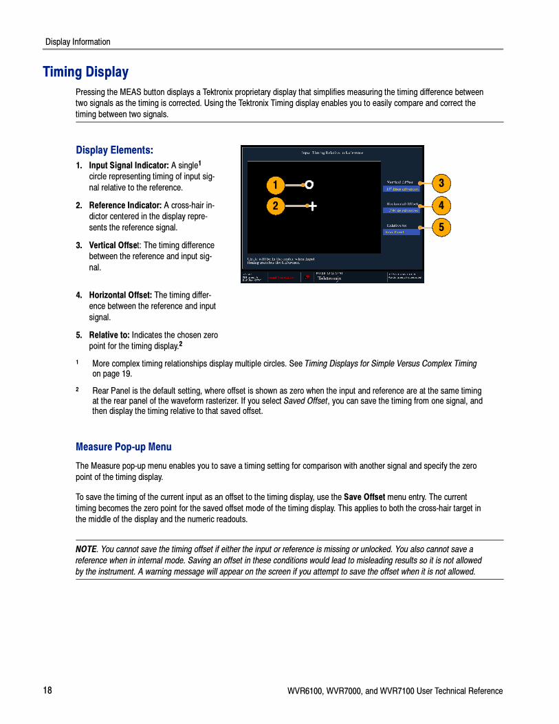
Timing Display
Pressing the MEAS button displays a Tektronix proprietary display that simplifies measuring the timing difference betweentwo signals as the timing is corrected. Using the Tektronix Timing display enables you to easily compare and correct the
timing between two signals.
Display Elements:
1. Input Signal Indicator: A single1
circle representing timing of input sig-
nal relative to the reference.
2. Reference Indicator: A cross-hair in-dictor centered in the display repre-
sents the reference signal.
3. Vertical Offset: The timing differencebetween the reference and input sig-
nal.
1
2
3
4
5
4. Horizontal Offset: The timing differ-ence between the reference and input
signal.
5. Relative to: Indicates the chosen zeropoint for the timing display.2
1 More complex timing relationships display multiple circles. See Timing Displays for Simple Versus Complex Timingon page 19.
2 Rear Panel is the default setting, where offset is shown as zero when the input and reference are at the same timingat the rear panel of the waveform rasterizer. If you select Saved Offset, you can save the timing from one signal, andthen display the timing relative to that saved offset.
Measure Pop-up Menu
The Measure pop-up menu enables you to save a timing setting for comparison with another signal and specify the zero
point of the timing display.
To save the timing of the current input as an offset to the timing display, use the Save Offset menu entry. The current
timing becomes the zero point for the saved offset mode of the timing display. This applies to both the cross-hair target inthe middle of the display and the numeric readouts.
NOTE. You cannot save the timing offset if either the input or reference is missing or unlocked. You also cannot save a
reference when in internal mode. Saving an offset in these conditions would lead to misleading results so it is not allowed
by the instrument. A warning message will appear on the screen if you attempt to save the offset when it is not allowed.

Display Information
WVR6100, WVR7000, and WVR7100 User Technical Reference 19
Save Offset allows you to measure the timing between inputs or to match multiple signals. To select the definition for thezero timing offset, use the Relative To: menu entry to select one of the following:
� Rear Panel, which means the timing offset will be shown as zero when the two signals are timed down at the rear ofthe waveform rasterizer.
� Saved Offset, which means that the timing will be shown as zero offset when the input signal matches the timing ofthe signal that was present when the offset was saved using the Save Offset menu entry.
This selection changes both the numeric readouts and the target in the middle of the timing display.
Timing Displays for Simple Versus Complex Timing
The number of circles, with each repre-senting a time offset, varies with the
complexity of the timing between the
reference and input signals. If you aretiming input signals with rates that are
integer multiples of the reference rates,the instrument can measure the timing
deterministically and displays the relation-
ship as one circle (offset) relative to thecross-hair (reference as is shown).
Such cases include timing an NTSC input
(multiplier of 1) or a 525 SDI input whoseframe time is 33.36 ms (multiplier of 2),
against an NTSC reference, which has a
frame time of 66.73 ms.
If you time input rates that are not integermultiples of the reference rates, the
instrument cannot measure the timing
deterministically, so it displays therelationships as several circles. Each
circle represents a possible timing offsetmeasurement relative to the reference
cross-hair. Display emphasis is given to
the circle that times closest to zero offsetand the numerical readouts track this pair.
Nondeterministic cases include timing of
slow rate inputs against fast frame-ratereferences or when timing video against
film rates.

Display Information
20 WVR6100, WVR7000, and WVR7100 User Technical Reference
For a case where multiple relationshipswould display, consider an input of
1080p/23.98 Hz with a reference of
NTSC/59.94 Hz:
� The different rates result in timing rela-
tionships between the signals that re-peat once for every four fields of the
input and five frames of the reference
(shown right).
� Because this allows for five possible
ways to measure timing between these
two signals, the timing display showsfour circles, with emphasis and read-
outs as previously described above.
Ref NTSC color frames
0 ms 50 ms 100 ms 150 ms 200 ms 250 ms 300 ms
Input 1080 p 23.98 frames
1080 p frame timing diagram --vs-- NTSC
Delay 1 Delay 2 Delay 3 Delay 4 Delay 5
Picture Display
Pressing the PICT button calls up the Picture display, which lets you see the picture generated by the video signal. Youcan choose to display the picture with or without a Picture Frame, VChip, Closed Captioning (CC), and Safe Area
Graticules.
Display Characteristics:
� In full-screen mode (shown), there isno cropping.
� Pictures are decimated horizontally or
vertically to achieve the correct aspectratio. This decimation may cause some
artifacts. This behavior may be evident
on a sweep signal.
� Also see the online help for the Picture
Aspect Ratio for related information.
� Display can be set to include ClosedCaptioning text overlaid on the picture.

Display Information
WVR6100, WVR7000, and WVR7100 User Technical Reference 21
VChip, CC-Display, and Safe AreaGraticule Characteristics:
1. VChip Area: Displays detected VChip
ratings from any of these systems:MPAA (US), TV (US), Canadian En-
glish, and Canadian French. VChip in-formation is labeled CA (Content Advi-
sory).
2. Safe Graticules: SMPTE, BBC, andARIB B-4 standards for safe area grati-
cules allow for selection of up to two
Safe Area and two Safe Title grati-cules. Custom graticles with adjustable
areas can also be specified.
3. Closed Caption Text Area: Displaysclosed captioning, configurable to de-
code to the following Closed Caption
standards:
� For Composite: EIA--608--line--21
� For SD: EIA--608--line--21,EIA--608--ANC, and EIA--608 (708)
� For HD: EIA--608--ANC, EIA--608
(708)
Safe Title Graticule
Safe Area Graticule
1
2
3
NOTE. See Monitoring Closed Captioning (CC) and Safe Area Compliance in the WVR6100, WVR7000, and WVR7100Quick Start User Manual.
PICT Pop-up Menu
The Picture pop-up menu enables you to optionally display elements of the video signal outside the active video, turn on
display of Close-Caption (CC) text overlaid on the picture, and turn on up to four save area graticules, and otherwisecontrol the PICT display.
To see only the active video portion of the signal, use the menu to switch Picture Frame to On; to see elements of thesignal outside the active video, switch Picture Frame to OFF to view user data, embedded audio, and elements in the
vertical interval.
NOTE. You can see signal elements outside the active video only when the PICT display is set to FULL. You will not be
able to see sync signal elements on Composite signals.
To view CC text overlaid on the display, use the menu to switch Display Closed Captions to ON.
To select the CC service used to display closed captions, use the menu to set EIA--608 CC Service to a CC or textchannel.

Display Information
22 WVR6100, WVR7000, and WVR7100 User Technical Reference
NOTE. If you set a PICT display for additional tiles, each one affords independent control of the CC setup. You can turn it
on for one tile and leave it off for another, or you can set it to display differently from one tile to another. Conversely, CC
configuration set in the CONFIG menu applies globally to all tiles set to PICT.
NOTE. To set the global configuration for CC decoding, use the Aux Data Settings submenu of the CONFIG menu. You
can set the CC transport type, services in pop-up, and other global parameters. See To Monitor Closed Captioning in the
WVR6100, WVR7000, and WVR7100 Quick Start User Manual for more information.
When monitoring to ensure that branding or other elements do not overlay essential text or video action, use the PICT
menu to select a Safe Action and Safe Title graticule. The Safe Action Area is the maximum image area within which all
significant action should be contained, and the Safe Title Area is the maximum image area within which all significant titlesshould be contained. You can select standard or custom safe area graticules.
To display safe area graticules overlaid on the display, use the menu to switch up to four Safe Area graticules settings toON.
NOTE. Select and/or define these graticules globally in the Graticules submenu of the CONFIG menu. You can set the
Safe Graticule Standard and define dimensions and offsets for custom Safe Graticules. See To Monitor for Safe Area
Compliance in the WVR6100, WVR7000, and WVR7100 Quick Start User Manual for more information.
Audio Display
Pressing the AUDIO button brings up the Audio Display. The Audio display provides level meters and a phase display formonitoring audio signals. The Audio display always shows the level meters and correlation meters. When you choose to
display the phase plot (also known as Lissajous), the left portion of the Audio tile displays the level meters and the right
portion the Phase display. If the Dolby Digital (option DD) or Dolby E (option DDE) option is installed, you can displaySurround Sound in the right part of the Audio Tile, instead of the phase plot. See the figure that follows.

Display Information
WVR6100, WVR7000, and WVR7100 User Technical Reference 23
Display Elements
Meter ballisticsreadout
Phase correlation meters
Level meterlabels
Level meterscale and units
Correlation meter for selectedpair (Phase Display only)
Test levelindicator
Peak levelindicator
Axes
Sourcelabels
Audiosource/setup
In-bar warningmessages
Level meters Phase or Surround sound display
Element Descriptions
Element Description
Level meters Can include Dolby channels 9 and 10 if Dolby options are present.
Phase or Surround display Selects between the Phase display, where the phase of a selected pair of channelsis plotted against an XY or sound-stage plot, and the Surround Display, where all
the channels levels display in positions matching their place in a surround-sound
listening environment.
Audio source/setup Displays selected audio input and related setup information, such as ListeningMode when in Surround display.
Level meter labels Identifies the signal in each meter bar. The labels vary according to whether theaudio sources to the level meter bars are normal channel pairs, surround channels,
or Dolby sources (the Dolby source labels include Dolby type).
Level meter ballistics readouts Displays the selected dynamic response characteristic.
Axes Shows the orientation of the two audio signals when displaying phase; shows theorientation and amplitudes of the sound field when displaying surround sound.
(Axes are selectable for an XY or Soundstage plot.)
Phase correlation meters Displays the phase correlation between the two-channel bars under which itappears. The meter of the pair selected for the Phase display also appears in the
Phase display.

Display Information
24 WVR6100, WVR7000, and WVR7100 User Technical Reference
Element Description
Test level and Peak programlevel indicators
Indicate, as diamond-shaped markers between the level bars, the configurablelimits set up for the display. Above the Test level, the bar displays in a yellow color.
Above the Peak level, the bar displays in a red color. Test level is also known as
Reference level or Line-up level.
Level meter scale and units By default, the units are in dB relative to full scale (dBFS) for digital inputs and dBrelative to 0.775 Volts (dBu) for analog inputs. The 0 dB mark is digital Full scale
for digital inputs and 0 dBu for analog inputs. You may also set the 0 dB mark to
either the Peak Program level or the Test level. See also CONFIG > Digital AudioDisplay > set meter type to, and CONFIG > Analog Audio Display > set meter type
to.
NOTE. The surround display is described under Monitoring Surround Sound in theWVR6100, WVR7000, and WVR7100
Quick Start User Manual.
Legacy Level Bars
Regarding the Level Bars in the Audio display, earlier-generation rasterizers shipped with audio boards that had different
default mappings of the input channel pairs to the level bars. These rasterizers used a default arbitrary assignment; thecurrent rasterizer assignment matches the order specified by the standard SMPTE 320M, reversing the assignments of the
second and third pair of channels compared to earlier rasterizers.
If you apply setups or presets that depend on the previous default assignments to current rasterizers that employ the
current default assignments, you will need to modify those presets to use the new assignments. Alternatively, you couldswap the inputs at the back of the rasterizer. You can also change the input to bar mapping in the CONFIG menu to any
order that you want (see How to Configure Audio Inputs in the WVR6100, WVR7000, and WVR7100 Quick Start User
Manual).
Above-bar Warning Messages
The waveform rasterizer displays warning messages above the level meter bars. The warning messages that can appearabove the bars as follows:
Clip. The number of consecutive samples equals or exceeds the # Samples for Clip setting.
OVER. The signal has been at or above the specified Over Level for a time exceeding the Duration for Over setting.
Display Information
WVR6100, WVR7000, and WVR7100 User Technical Reference 25
In-bar Warning Messages
The waveform rasterizer displays warning messages within the level meter bars. The warning messages that can appear
are shown below in order of priority.
UNLOCKED. The instrument is not locked to an incoming signal on the indicated input channel. Data cannot be decodedand all data and other errors are ignored. This means that if an AES input is selected, nothing recognizable is present on
the input, or if embedded audio is selected, the VIDEO input is unrecognizable.
AES PARITY. The incoming subframe does not have even parity as specified by the digital audio standards. The data
sample is unreliable and is ignored. The level meters and Lissajous display treat the sample as a zero sample.
AES CRC ERROR. The CRC code in the AES channel status packet is incorrect. Sometimes the CRC code is set to zero,
indicating that the signal is missing; when this is the case, this message is not displayed.
MUTE. The number of consecutive all-zero samples equals or exceeds the # Samples for Mute setting.
SILENCE. The signal has been at or below the specified Silence Level for a time exceeding the Duration for Silencesetting.
DISABLED. Indicates that an audio bar is not active. This message is mainly seen with a Dolby Digital source when alistening mode is selected with a reduced number of channels.
AES V BIT. Indicates that the Validity bit is set high for one or more data samples. In the AES/EBU standard, a set validitybit indicates that the sample is not suitable for conversion to audio. By default, the level meter bars and Lissajous display
treat the affected samples as zero samples.
NO AUDIO. Indicates that an AES or embedded input has the Non audio bit set.
NOT PRESENT. Indicates that an audio bar is not present in the current audio input. This can be present if a Dolby Digitalinput has a coding mode indicating a reduced number of channels.
DOLBY D. Indicates an AES or embedded input is Dolby Digital.
DOLBY E. Indicates an AES or embedded input is DOLBY E.
Audio Pop-up Menu
The Audio pop-up menu enables you to select the audio input source and specify whether a phase display or asurround--sound displays appears in a subtile to the right of the level meter display.
To select the source for the Audio display, select Audio Input in the menu and set a source. The number of availablesources depends on which audio option is installed. Choosing any given input will make that audio the monitored signal
regardless of which video input is active. Alternatively, you can choose Follows video to enable the mapping that allows
changing the audio source as the video input selection is changed.
NOTE. Use the CONFIG menu to select the mapping of input to bar, the meter type, and the Follows video mapping of
audio to video.

Display Information
26 WVR6100, WVR7000, and WVR7100 User Technical Reference
To add a 2-channel phase display to the audio tile, set Aux Display to Phase Display in the Audio pop-up menu. A phasedisplay is also called a “Lissajous” display.
To choose the plot style of the Phase Display, select between the following two entries in the pop-up menu:
� Sound Stage has axes rotated at a 45 degrees.
� X-Y has axes that are horizontal and vertical.
To choose the pair of inputs that is displayed in the phase display, select Phase Pair and set a value. You can also selectCustom, and then specify individual channels for the input pair, using the Phase Channel A and Phase Channel B entries.
To add a multi-channel surround sound display to the audio tile, set Aux Display to Surround Sound in the Audio pop-upmenu. You can also enable either or both of the following entries:
� Dominance Indicator. When on, indicates the location of the dominant sound in the surround sound image using across--hairs pointer (surround display only).
� Surround Filter. When set to Linear, results in a non-weighted response; when set to A--weighted, results in a response
that more closely matches that of the human ear.
NOTE. The Audio Surround Sound display is courtesy of Radio-Technische Werkstaetten GmbH & Co. KG (RTW) of
Cologne, Germany.
LTC Waveform Display
Pressing the OTHER button brings up a display of an LTC waveform when one is present. This enables you to check the
LTC amplitude and noise, and verify that LTC is locked to the video. The display has two vertical scales, one in Volts andthe other in dBu.
Display Elements:
1. Vertical Scale (V): The vertical displayscale in volts.
2. Time Code: when displayed, indicates
that the LTC time code is locked to thevideo.
3. Horizontal Scale: The horizontal dis-
play scale.
4. Vertical Scale (dBu): The vertical dis-
play scale in dBu.
1
4
32

Display Information
WVR6100, WVR7000, and WVR7100 User Technical Reference 27
OTHER (LTC) Pop-up Menu
The Other pop-up menu provides access to the Center Waveform function. The Center Waveform function is used to
cancel any horizontal or vertical position adjustments and restore the trace to the default position. After bringing up thepop-up menu, press SEL to center the waveform.
Gamut Display
Pressing the GAMUT button calls up the Gamut Display. The Gamut display provides three proprietary Tektronix display
types to enable you to easily and quickly check the gamut of an SDI signal. You can choose from the Arrowhead,Diamond, and Split Diamond displays. The Arrowhead display provides NTSC and PAL composite gamut information
directly from the SDI signal. The Diamond and Split Diamond displays provide a reliable method of detecting invalid colors.
Display Elements:
1. High threshold: Shows the currentlyspecified high threshold (Diamond
High or Arrowhead Max).
2. Low threshold: Shows the currentlyspecified low threshold (Diamond
Low).
3. Gamut display type: Shows the se-lected Gamut display type -- Diamond,
Split Diamond, or Arrowhead.
4. Threshold indicators: Indicates thethe threshold settings using blue
dashed lines.
1
2
3 4
GAMUT Pop-up Menu
The GAMUT pop-up menu allows you to select the type of gamut display shown in the active tile. To change the display
type in the GAMUT display, use the pop-up menu to select from the following displays:
� Diamond shows Gamut violations of the SDI input if translated to RGB color space.
� Split Diamond offsets the two halves of the Diamond to allow you to better see negative RGB Gamut errors.
� Arrowhead shows Gamut violations of the SDI input if translated to the Composite domain.

Display Information
28 WVR6100, WVR7000, and WVR7100 User Technical Reference
Status Display
Pressing the STATUS button calls up the Status display, which provides several views of signal status. Status displays aretext displays that show signal status. You can view current alarms and errors (those occurring now and within the last few
seconds), a history of errors and alarms (up to 10,000 entries), video error statistics or audio error statistics. You candisplay a different Status display type in all four tiles.
NOTE. Press the HELP button and then press the STATUS button to explore help topics on the following status types.
Status display types available:
1. Video Session: Control the VideoSession settings.
2. Audio Session: Control the Audio
Session settings.
3. Aux(iliary) Data Status: View closed-
caption and V-chip related status and
mute related alarms.
4. Dolby Status: View Dolby metadata
for the currently monitored audio
source. You can also select the DolbyE program supplying the status for Op-
tion DDE equipped instruments.
1 2
3 4
5. Error Log: Control the error loggingsettings.
6. Alarm Status: View current alarm sta-
tus.
7. ARIB Status: Check for the presence
and status of ARIB-based informationencoding. The rasterizer supports
TR-B.22, TR-B.23-1, TR-B.23-2, B.35,
B.37, and B.39 ARIB standards. Toview the ARIB content displays, enable
this option in CONFIG > Aux Data
Settings > ARIB Content Display.
5 6
7

Display Information
WVR6100, WVR7000, and WVR7100 User Technical Reference 29
8. SDI Status: View two measurementsof signal jitter cable loss in both dB
and meters of the selected cable type,
and calculated source level. With op-tion PHY, automatic measurements of
eye amplitude, rise time, fall time, andrise-fall difference are also displayed.
8
9. Audio Control: View the informationon audio frame number, sampling fre-
quency, active channels,
and relative audio-to-video delay ofeach channel, as encoded in the audio
control packet metadata. 9
STATUS Pop-up Menu
The STATUS pop-up menu enables you to mute alarms, select the type of display that appears in the status screen, and
set options related to the selected display type.
STATUS Colors
The STATUS display messages and values appear in different colors to help indicate signal status:
Color Description
White Identifies informational items and represents changes in the instrument state
Green Indicates error conditions that have cleared
Yellow Indicates that there is a warning condition (that might require attention) or that an error has occurredwithin 2 seconds
Red Indicates signal information that has been found to be in an ongoing error state
Gray Indicates alarm status state of an un-enabled alarm
Display Information
30 WVR6100, WVR7000, and WVR7100 User Technical Reference
Eye Display
For waveform rasterizers equipped with Option EYE, pressing the EYE button calls up the Eye display (for SDI inputsonly). The Eye display presents an eye pattern diagram of the SDI input, which lets you verify electrical characteristics of
the SDI transport layer. You can measure analog characteristics of the SDI input on the eye pattern using the graticule orvoltage and time cursors. Two jitter indicators provide two independent measurements of jitter. You can also set alarms on
various parameters (see your instrument online Help). For more information on jitter, search the Tektronix Web site for jitter
application notes.
NOTE. If you have an early instrument that has been upgraded with an Eye option, but that does not have a dedicated
front-panel button EYE button, both the EYE Display and the Timing Display are accessible under the MEAS button. To
view the EYE Display with such an instrument, press and hold the MEAS button and select Display Type > Eye Display.
With the EYE Display selected, the display and MEAS pop-up menu behave as described below. Selection of the Timing
Display and pop-up menu are described under Timing Display on page 18. If you use a remote front panel without an Eye
button, but the local instrument has an Eye button, the instrument will use the oldest front panel version.
Option EYE is available only for the WVR6100 and WVR7100.
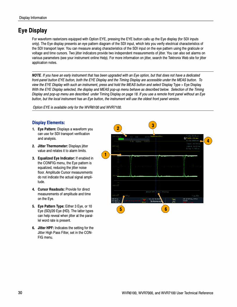
Display Elements:
1. Eye Pattern: Displays a waveform youcan use for SDI transport verification
and analysis.
2. Jitter Thermometer: Displays jittervalue and relates it to alarm limits.
3. Equalized Eye Indicator: If enabled in
the CONFIG menu, the Eye pattern isequalized, reducing the jitter noise
floor. Amplitude Cursor measurements
do not indicate the actual signal ampli-tude.
4. Cursor Readouts: Provide for directmeasurements of amplitude and time
on the Eye.
5. Eye Pattern Type: Either 3 Eye, or 10Eye (SD)/20 Eye (HD). The latter types
can help reveal when jitter at the paral-
lel word rate is present.
6. Jitter HPF: Indicates the setting for the
Jitter High Pass Filter, set in the CON-
FIG menu.
2
1
3
5 6
4

Display Information
WVR6100, WVR7000, and WVR7100 User Technical Reference 31
At the end of a long cable, the eye diagram may appear so noisy that there is little or no discernable opening. In thissituation, limited use of the eye diagram is still possible by selecting Equalized Eye mode. The equalizer compensates for
the effects of cable length by applying an inverse response function and then reslicing the signal to a logic level. This
causes amplitude information to be lost, but preserves the effects of jitter in the signal.
If the equalized eye display appears clear with a substantial eye opening, then the signal is likely to be recovered
error-free. However, if it appears noisy with little eye opening, then there is more potential for data errors to occur in thereceiver.
NOTE. For information on taking Eye measurements, see the How to Monitor the SDI Physical Layer section of the
WVR6100, WVR7000, and WVR7100 Quick Start User Manual.
Eye Pop-up Menu
Pressing the MEAS button on the front panel will bring up the Eye pop-up menu. This menu enables you to center the eye
waveform and, more importantly, specify the operation of the Jitter detector that drives the Eye display.
NOTE. Eye diagrams that you display in the upper two display tiles are driven by the Jitter1 detector; those in the lower
two tiles, by the Jitter2 detector. To display two Eye diagrams with independent Jitter detectors, display one in an upper tile
and one in a lower tile.
Jitter Display
The Jitter Display can be used once you have configured the instrument for Eye measurements and is only available with
option PHY. This display shows you the wave shape of the jitter and allows you to view additional time-domain information,
such as whether there are jitter components that are synchronous or nearly synchronous to the video line or frame. Youcan also set alarms on various parameters (see your instrument online Help). For more information on jitter, search the
Tektronix Web site for jitter application notes.
NOTE. Option PHY is available only for the WVR6100 and WVR7100.

Display Information
32 WVR6100, WVR7000, and WVR7100 User Technical Reference
Display Elements:
1. Jitter Waveshape: Displays the jitterwave shape (the image to the right
shows no jitter). This shape is modified
by the high-pass filter (HPF) setting.
2. Jitter Thermometer: Displays jitter
value and relates it to alarm limits.
3. Jitter HPF: Indicates the setting for theJitter High Pass Filter, set in the CON-
FIG menu.
2
1
3
High-Pass Filter. The high-pass filter bandwidth setting allows you to show only jitter terms above the selected filter
frequency. When you select a filter setting, depending on the active input signal, you select the jitter measurement type(Timing, Alignment, or neither, as defined by the SMPTE standard). Use the High Pass Filter soft key to select the lowest
settings to measure timing jitter and the higher settings to measure alignment jitter.
To choose the Jitter detector filter, use the Measurement pop-up menu and choose one of the following settings for the
Jitter HP Filter entry:
Setting Description
Timing Sets the detector high-pass filter to 10 Hz. This is the correct value for mea-suring timing jitter for both SD and HD signals.
Align Sets the detector high-pass filter to 1 kHz, as specified by SMTPE, for SDsignals; and to 100 kHz for HD signals. These are the correct values formeasuring alignment jitter.
10 Hz, 100 Hz, 1 kHz, 10 kHz, 100 kHz Sets the detector high-pass filter to the selected value.
Jitter Pop-up Menu
The Jitter pop-up menu is accessed by pressing the MEAS button on the front panel. This menu enables you to set theJitter HPF value, center the waveform, show or hide the meter readout, and change the display type.
NOTE. For instructions on how to take jitter measurements, see the To Take Jitter Measurements section in the WVR6100,
WVR7000, and WVR7100 Quick Start User Manual.

Supplemental Operating Information
WVR6100, WVR7000, and WVR7100 User Technical Reference 33
Supplemental Operating InformationThis section contains topics that, though of less general interest, may address your particular application needs. These
applications include cloning setups, upgrading firmware, and a description of cable types.
Cloning Setups (Presets)
Given the complexity of SDI and other Video signals, waveform rasterizer setups can become complex as you tailor themto monitor the parameters you want. To save setup time and ensure consistency, you can save waveform rasterizer setups
as presets in the rasterizer. For the same reasons, you might also want to clone setups to use in setting up other waveform
rasterizers. Saving and recalling of presets in the same instrument is covered in To Use Presets in the WVR6100,
WVR7000, and WVR7100 Quick Start User Manual. This section deals with using presets to clone setups.
Using a Web Browser, Java Applet, or Java Application
The Java Application provides a complete cloning solution. From the Java Application, you can:
� Save the current rasterizer setup to a <filename>.PRS file
� Restore the <filename>.PRS file to the same rasterizer or to a different rasterizer, overwriting the current setup of the
target rasterizer
� Select up to all five of Presets 1 -- 5 and save them into a single <filename>.PRE file
� Restore the <filename>.PRE file to the same rasterizer or to a different rasterizer, overwriting any stored presets on the
target rasterizer that conflict with the new presets. If a preset was not stored in the file, uploading the PRE file leaves itunaffected on the target.
The Web browser only provides the first capability from the above list for the Java Application.
The Java Applet cannot save settings to, or restore them from, a file.
From a Web Browser
The Web browser provides a quick way to capture individual presets for later upload to other rasterizers (or the same
rasterizer). Saved files are *.PRS files, and can only be uploaded to the rasterizer as an overwrite to the current instrumentsetup, not to Preset 1 -- Preset 5, and only by using the Java Application (see From the Java Application on page 34).
Saving to a file
1. Connect to the networked waveform
rasterizer from your networked PC us-
ing your PC resident Web browser.See Using a Web Browser on page 4 if
you need instructions.

Supplemental Operating Information
34 WVR6100, WVR7000, and WVR7100 User Technical Reference
2. Click to save a copy of the current set-tings of the networked rasterizer to a
local file.
3. Click any preset from 1 to 5 to save acopy of that preset from the networked
rasterizer to a local file.
3
2
4. In the Save As dialog box that dis-plays, navigate to the location in which
you want to save the preset.
5. Rename the file if desired.
6. Click the Save button to save the pre-
set in a file.
To recall a preset that you have stored to
a file, you must use the Java Application.
(See From the Java Application onpage 34.)
4
5 6
From the Java Application
You can save and upload rasterizer Presets to files from the Java Application. This application provides the only way to
later upload to other rasterizers (or to the same rasterizer); the Web browser and the Java Applet cannot upload presets.
NOTE. If you have instrument firmware version 2.0 and greater, using the Java application, you can auto-save snapshots
with multiple settings by right clicking in the remote display window.
Java Application Requirements
If you install Java on your PC, you can launch a Java applet to control the waveform rasterizer. The Java Applet requires:
� A computer running on any platform that supports Java version 1.4.1 or later, including Windows NT/2000/XP, Linux,
Unix, and Mac OS X.
� Java Standard Runtime Environment version 1.4.1 or later. The Java runtime must already be installed on your system
in order to use the Java application.
� The Java application package (wvr7100.zip) from the Tektronix Web site, installed on the computer.
� The waveform rasterizer, networked or otherwise connected for remote control from the computer.
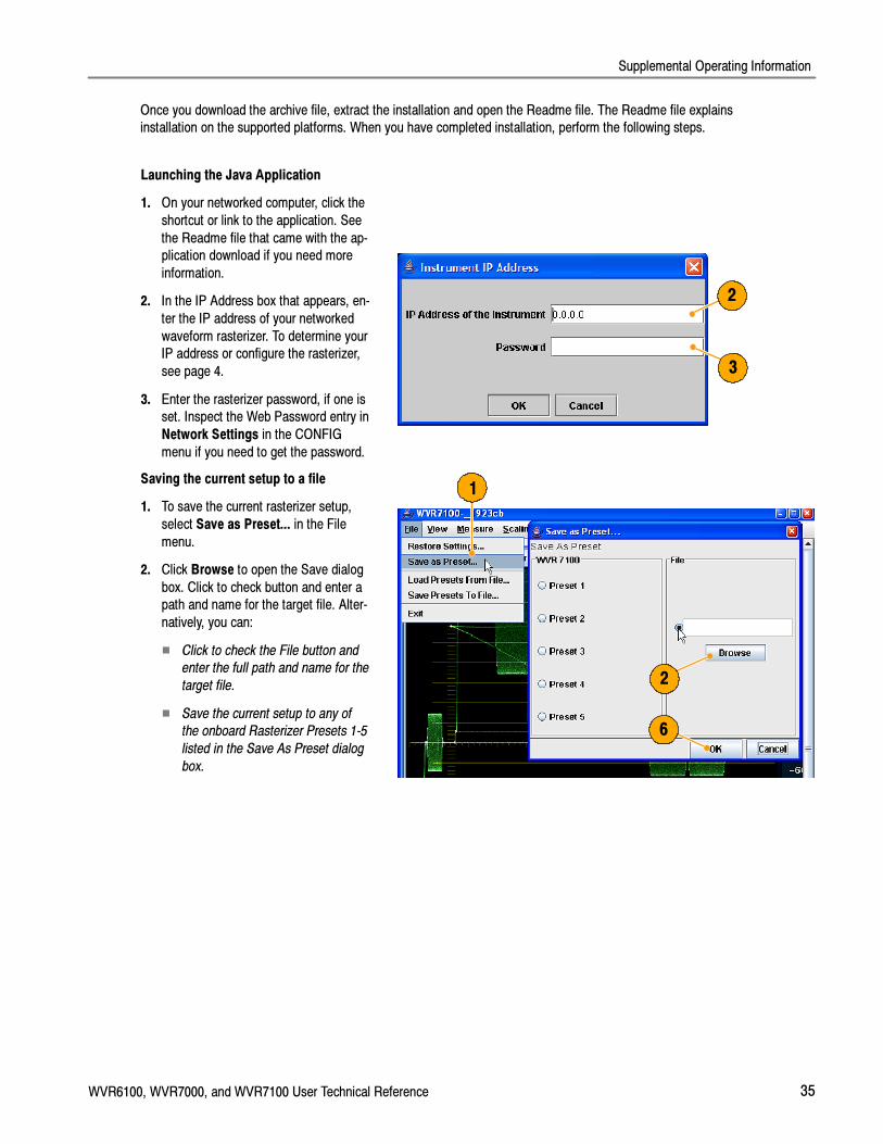
Supplemental Operating Information
WVR6100, WVR7000, and WVR7100 User Technical Reference 35
Once you download the archive file, extract the installation and open the Readme file. The Readme file explainsinstallation on the supported platforms. When you have completed installation, perform the following steps.
Launching the Java Application
1. On your networked computer, click the
shortcut or link to the application. See
the Readme file that came with the ap-plication download if you need more
information.
2. In the IP Address box that appears, en-
ter the IP address of your networked
waveform rasterizer. To determine yourIP address or configure the rasterizer,
see page 4.
3. Enter the rasterizer password, if one isset. Inspect the Web Password entry in
Network Settings in the CONFIG
menu if you need to get the password.
3
2
Saving the current setup to a file
1. To save the current rasterizer setup,
select Save as Preset... in the File
menu.
2. Click Browse to open the Save dialog
box. Click to check button and enter apath and name for the target file. Alter-
natively, you can:
� Click to check the File button and
enter the full path and name for the
target file.
� Save the current setup to any of
the onboard Rasterizer Presets 1-5
listed in the Save As Preset dialog
box.
1
2
6
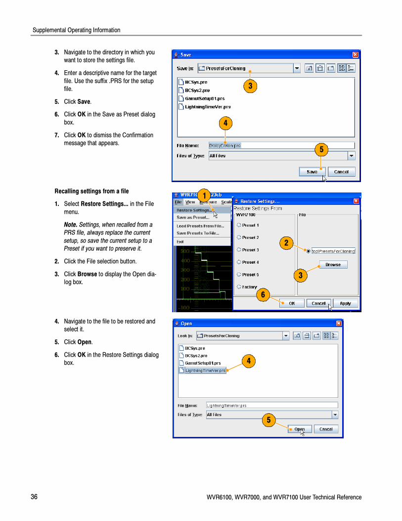
Supplemental Operating Information
36 WVR6100, WVR7000, and WVR7100 User Technical Reference
3. Navigate to the directory in which youwant to store the settings file.
4. Enter a descriptive name for the target
file. Use the suffix .PRS for the setupfile.
5. Click Save.
6. Click OK in the Save as Preset dialog
box.
7. Click OK to dismiss the Confirmationmessage that appears.
4
5
3
Recalling settings from a file
1. Select Restore Settings... in the File
menu.
Note. Settings, when recalled from a
PRS file, always replace the current
setup, so save the current setup to a
Preset if you want to preserve it.
2. Click the File selection button.
3. Click Browse to display the Open dia-log box.
1
3
6
2
4. Navigate to the file to be restored andselect it.
5. Click Open.
6. Click OK in the Restore Settings dialogbox. 4
5

Supplemental Operating Information
WVR6100, WVR7000, and WVR7100 User Technical Reference 37
Saving all Presets to a file
1. To save the rasterizer Presets (Preset
1-5) into a single file, Save Presets to
File... in the File menu.
2. Click to check the boxes for all Presets
that you want to save.
3. Click ... to open the Save dialog box.
1
32
4. Navigate to the directory in which youwant to store the settings file.
5. Enter a descriptive name for the file,
and click Save. Use the suffix .PRE forthe setup file.
6. Click Save in the Save Presets to Filedialog box.
7. Click OK to dismiss the Confirmation
message that appears.
4
5
6
Recalling Presets from a file
1. If cloning the saved presets to another
rasterizer, close and relaunch the Java
Application, entering the IP of that ras-terizer. See Launching the Java Ap-
plication on page 35.
2. Select Load Presets From File in the
File menu.
3. Click the ... button to display the Opendialog box.
2
3
6

Supplemental Operating Information
38 WVR6100, WVR7000, and WVR7100 User Technical Reference
4. Navigate to the file to be restored andselect it.
5. Click Open.
Caution. The next step will restore files to
the same Preset locations on the rasteriz-
er that they were saved from when stored
to file. This will overwrite any existing
setups in those locations.
6. Click OK in the Load Presets from Filedialog box.
7. Repeat this procedure to clone setups
to other rasterizers as needed.
4
5
Usage Notes
When saving presets as files for later cloning to other rasterizers, take note of the following:
� Option configuration mismatch between Clone source preset and the target result in some different setup parameters.
The target accepts only the common setup parameters. Parameters not supported by the target are ignored:parameters not supported in the source remain unchanged in the target.
� Model mismatch (WVR6100, WVR7000, or WVR7100) between Clone source preset and the target result in somedifferent setup parameters. The target accepts only the common parameters setup parameters. Parameters
unsupported by the target are ignored: parameters not supported in the source remain unchanged in the target.
� Rasterizers with early versions of firmware have some default settings that do not match those of rasterizers that
shipped with this manual. If the source preset contains settings left at defaults for an earlier firmware version, they willbe set to the defaults for the later firmware version in the target.
Upgrading the Waveform Rasterizer Firmware
System Upgrade (CONFIG > Utilities > System Upgrade) is used to upgrade the system software of the WVR6100,
WVR7000, and WVR7100 Waveform Rasterizers. The upgrade is performed across an Ethernet network using a PC to
transfer the new software to the waveform rasterizer.
PC System Requirements
The data-transfer utility for upgrading the waveform rasterizer runs on these PC systems: Windows 98, Windows NT 4.0,Windows ME, Windows 2000, and Windows XP.
The data-transfer utility also requires Winsock 2.0, an ethernet interface, and 10 MB of free disk space be present on thePC system.

Supplemental Operating Information
WVR6100, WVR7000, and WVR7100 User Technical Reference 39
Before You Begin
Before performing Installing the Firmware on page 40, read about possible fault conditions and their remedies, and about
how the waveform rasterizer uses button animation to signal upgrade progress and events.
FAULT Recovery and Cautions
� The boot monitor will assert a FAULT after an unsuccessful firmware update operation. The failure of the firmwareupdate can be caused by a network communication error, time-out, or a corrupt firmware package. When it detects a
firmware update error, the instrument returns to the ready state (tile buttons flashing).
In this event, you can try to resend the firmware data to the instrument. In the case of repeated failures, check to make
sure that you have the correct firmware release for the instrument.
� The boot monitor might also detect errors in the DHCP software which can result from repeatedly switching between
factory and DHCP network settings. The FAULT light remains lit and the instrument fails to obtain an address from a
DHCP server.
In this event, reboot the instrument by pressing one of the MEASURE SELECT buttons or by removing power from the
instrument. When the instrument reboots, hold down the FULL button to return the instrument to the firmware updatemode.
� When using DHCP, there is a small possibility that the waveform rasterizer will be assigned a different address whenthe software update mode is activated. (If the unit is not off or disconnected from the network for very long, then
typically the waveform rasterizer will get the same address as it had previously.)
In this event, you may need to abort the update (see CAUTION that follows), go the Config menu and get the current
IP address, and use that address in the update process. If this does not work the first time, you may need to try again
or use the manual IP address mode. Alternatively, you can temporarily set the IP address to the default value(192.168.1.1) once it is in upgrade mode by pressing SEL, and use that address in the upgrade procedure. After the
upgrade is completed, the original IP address will be restored.
CAUTION. Once the instrument has started to erase internal flash memory (VECT button lit), DO NOT remove power from
the instrument. If you do so, the instrument will only boot in the firmware update mode until new firmware has been loaded
into the instrument flash memory. Therefore, use the MEASURE select buttons to abort a firmware update. Remove power
from the instrument only as a last resort.
� The instrument will automatically switch to factory default if DHCP discovery fails. Press the SEL button to restartDHCP discovery.
NOTE. FAULTS will not be logged into the diagnostic log because the boot monitor is running, not the main instrument
software.

Supplemental Operating Information
40 WVR6100, WVR7000, and WVR7100 User Technical Reference
Button Animation During Upgrade
Button indication State Description
Flashing DISPLAYSELECT buttons
Ready Instrument is ready to receive firmware data and iswaiting for a connection from the PC host
Flashing arrow buttons DHCP discovery Instrument is negotiating for an IP address from aDHCP server
SEL button lit Factory IP configuration Instrument is configured with factory default IPaddress of 192.168.1.1
Arrow and SEL not lit Manual IP configuration Instrument is configured with manual IP configuration
Arrow buttons lit,SEL not lit
DHCP configuration Instrument has received an IP address from a DHCPserver
WFM button lit Receiving firmware Instrument is receiving firmware data
VECT button lit Erasing flash memory Instrument is erasing internal flash memory
MEAS button lit Programming flash memory Instrument is programming internal flash memory
1X button lit Verifying flash memory Instrument is verifying programming of internal flashmemory
Installing the Firmware
To install new firmware in a waveform rasterizer:
Download the Firmware Package
1. To download the latest version of the
waveform rasterizer firmware, navigate
to the Tektronix Web site at thehttp://www.tek.com/Measurement/vid-
eo_audio.
2. Click on the Download Software link,
select the Video Test, and search on
WVR to locate the waveform rasterizerfirmware-upgrade package and down-
load it.2
1
3. Click the downloaded archive and ex-tract the archived files into a directory
of your choice. The files to be ex-
tracted are transfer.exe and read-me.txt.
4. Extract the following files:transfer.exe, firmware.pkg and
readme.txt.
4
3

Supplemental Operating Information
WVR6100, WVR7000, and WVR7100 User Technical Reference 41
5. Write down the number listed for the IPAddress in the menu. This address
will also appear on the update screen.5
Enter System Upgrade Mode
6. On the waveform rasterizer, press the
left-arrow key to return to the main
CONFIG menu and select Utilities.
7. Highlight System Upgrade, and press
SEL. This displays the System Soft-ware Upgrade window.
8. To continue with the upgrade, press
the right-arrow key to select Continueand press SEL.
The monitor display goes to black and
the DISPLAY SELECT keys flash insequence.
6
7
8
9. If the arrow keys also flash, the wave-form rasterizer is in DHCP mode. Wait
until the arrow keys stop flashing be-
fore proceeding.9

Supplemental Operating Information
42 WVR6100, WVR7000, and WVR7100 User Technical Reference
Run the Upgrade
10. On the PC, double-click the trans-
fer.exe file to launch the transfer pro-
gram. This displays the window shownat right.
11. Type the network address (for exam-ple: 128.181.221.002) or DNS name of
the waveform rasterizer you want to
update. Make sure to delete anyleading zeroes, as shown in the exam-
ple in the illustration.
Press Enter.
11
10
NOTE. To stop the firmware update,
you can press any MEASURE button
on the front-panel of the waveform
rasterizer before the words Erasing
Flash... appear in the transfer utility
window.
12. The transfer utility displays done when
the software upgrade completes.
When the software upgrade completes,the waveform rasterizer will reboot.
12
13. To update another waveform rasterizer,begin at step 5 and skip step 10. If you
won’t be updating another waveform
rasterizer, press Enter to exit the trans-fer utility.
Upgrading Multiple Instruments
You can upgrade several instruments in in one session, one at a time, if you have determined their addresses. To upgrade,
use the Windows Command Prompt. Enter the following line in a Command Prompt window (substituting the addresses ofyour machines):
���������� �� ������� �� ������ �� �������
Separate the addresses with a space.
Alternatively, you can use file redirection to input the IP addresses to the transfer.exe utility. To do this, create a text file
containing a carriage-return delimited list of IP addresses or DNS names for the instruments to be updated. If you created
a text file named HOSTS.TXT, you would enter the following command to update a group of instruments:
���������� � ��������

Supplemental Operating Information
WVR6100, WVR7000, and WVR7100 User Technical Reference 43
NOTE. You can also place the waveform rasterizer into the upgrade mode by pressing the FULL button while applying
power to the instrument.
Verifying the Upgrade
After you have completed the firmware upgrade, the instrument will reboot and come up in an operational mode.
To verify the functional performance of your instrument, perform the Incoming Inspection procedures starting on page 11.
NOTE. See the Readme.txt file that is included with the firmware-upgrade package to determine whether all of the current
Configuration menu and instrument-mode settings are preserved through upgrading.
Description of Cable Types
The Cable Type selection in the CONFIG > Physical Layer Settings menu enables you to specify the type of cable that
most closely matches the cable used to connect the signal source to the waveform rasterizer. The following is a list ofsupported cable type descriptions:
� Belden 8281. Coax-Double Braided RG-59/U Type Number of Coax: 1 RG Type: 59/U AWG: 20 Stranding: Solid
Conductor Material: BC- Bare Copper Insulation Material: PE-Polyethylene Outer Shield Material: TC-Tinned
Copper/TC-Tinned Copper Outer Jacket Material: PE-Polyethylene Plenum (Y/N): N Plenum Number: 88281 Nom.Characteristic Impedance: 75ohm Applications: Precision Video Cable for Analog and Digital, Double Braided
RG--59/U Type, Broadband Coax, Headend/Video Cables, Precision Video Cable for Analog and Digital, RG-59/U
Type
� Belden 1694A. Coax-Low Loss Serial Digital Coax Number of Coax: 1 RG Type: 6/U AWG: 18 Stranding: Solid
Conductor Material: BC-Bare Copper Insulation Material: Gas-injected FHDPE-Foam High Density Polyethylene OuterShield Material Trade Name: Duofoil: Outer Shield Material: Aluminum Foil-Polyester Tape-Aluminum Foil/TC-Tinned
Copper Outer Jacket Material: PVC-Polyvinyl Chloride Plenum (Y/N): N Plenum Number: 1695A Nom. Characteristic
Impedance: 75ohm Applications: Precision Video Cable for Analog and Digital, Low Loss Serial Digital Coax, VideoCable, Precision Video Cables for Analog and Digital Applications, Precision Video Cable for Analog and Digital,
RG--6/U Type
� Belden 1505. Coax-RG-59/U Type Number of Coax: 1 RG Type: 59/U AWG: 20 Stranding: Solid Conductor Material:
BC-Bare Copper Insulation Material: Gas-injected FHDPE-Foam High Density Polyethylene Outer Shield MaterialTrade Name: Duofoil: Outer Shield Material: Aluminum Foil--Polyester Tape-Aluminum Foil/TC-Tinned Copper Outer
Jacket Material: PVC-Polyvinyl Chloride Plenum (Y/N): N Plenum Number: 1506A Nom. Characteristic Impedance:
75ohm Applications: Broadband Coax, Headend/Video Cables, Video Cable, Precision Video Cables for Analog andDigital Applications, Precision Video Cable for Analog and Digital, RG--59/U Type
� Belden 1855A. Coax-Sub-Miniature Number of Coax: 1 RG Type: Sub--miniature 59/U AWG: 23 Stranding: SolidConductor Material: BC-Bare Copper Insulation Material: Gas-injected FHDPE-Foam High Density Polyethylene Outer
Shield Material Trade Name: Duofoil: Outer Shield Material: Aluminum Foil--Polyester Tape-Aluminum Foil/TC-Tinned
Copper Outer Jacket Material: PVC-Polyvinyl Chloride Plenum (Y/N): N Nom. Characteristic Impedance: 75ohmApplications: Video Cable, Precision Video Cables for Analog and Digital Applications, Precision Video Cable for
Analog and Digital, Sub-Miniature, Precision Video Cable for Analog and Digital, Sub-Miniature RG-59/U Type
� Canare L-5CFB. Coax-Solid Copper Center Conductor; Foam PE Dielectric Tinned Copper Braid + 100% Foil Shield
Dielectric; 100% Sweep Tested; Nominal O.D. in. (mm): .303 (7.7); PVC Jacket Thickness in. (mm): .043 (1.1)
Supplemental Operating Information
44 WVR6100, WVR7000, and WVR7100 User Technical Reference
� Image 1000. Coax-Conductor size: nominal mm 1.0; Conductor material: Copper, Plain; Dielectric material: CellularPE; Inner Screen: Aluminium Polyester Tape; Outer Screen: Tinned Copper Braid 95%; Jacket Material: LSOH (PVC
to special order); Nominal Diameter: mm 6.8; Cable weight: kg/km 60.0; Impedance ohms (+/--1): 75.0 Capacitance
(nominal): p/F/m 56.0 DC resistance max ohms/100m: 2.19 Velocity of propagation %: 83.0

Index
WVR6100, WVR7000, and WVR7100 User Technical Reference 45
Index
AAlarm Status, Status pop--up menu, 28Arrowhead, Gamut pop--up menu, 27Audio
Above--bar warnings, 24AUDIO button, 22Display, 22Display, elements of, 23In--bar warnings, 23, 25Legacy level--bar defaults, 24Level meters, 23Pop--up menu, 25
Audio Session, Status pop--up menu, 28Aux Data, Status pop--up menu, 28
BBar Targets, Vector pop--up menu, 17Basic operation, 15
CCable types, 43Center Waveform
Other pop--up menu, 27Vector pop--up menu, 17, 21, 22Waveform pop--up menu, 16
Chroma, Waveform pop--up menu, 16Cloning Setups (Presets), Task descrip-
tion, 33Closed Caption, Display, characteristics
of, 21Safe Area Graticules, Display character-
istics of, 21Color code, Status display, 29
DDiamond, Gamut pop--up menu, 27Documentation
Conventions used in, vPurposes of, v
Dolby, Level meters, 23Dolby Status, Status pop--up menu, 28
EError Log, Status pop--up menu, 28
FFilter, Waveform pop--up menu, 16Flat, Waveform pop--up menu, 16Flat + Luma, Waveform pop--up menu,
16Follows video, Audio pop--up menu, 25
GGamut
Display, 27Display, elements of, 27GAMUT button, 27Pop--up menu, 27
GAMUT button, 27
HHorizontal Offset, Timing display, 18How to...
Connect to a network, 1connect to a network, 1operate your waveform rasterizer,
15
IIncoming inspection, 11Inspection, Incoming, 11Installation, Instructions, 1–14Installing firmware, 40IP settings, 1
JJava applet
Accessing remote interface, 5Limitation of, 33
Java ApplicationObtaining package, 34Requirements, 34Clone Setups (Presets), 33
LLightning, Vector pop--up menu, 17, 30Lissajous Snd Stage, Audio pop--up
menu, 26Luma, Waveform pop--up menu, 16
MManuals
Conventions used in, vPurposes of, v
MEAS button, 18Measure
Display, 18Display, elements of, 18MEAS button, 18Pop--up menu, 18
MeasurementRelative to:, 18Save Offset, 18
NNetwork
Connect to, 1IP settings, 1SNMP settings, 3
OOperation
Basic, 15Verification, 11
LTC, Display, 26Other
Display, elements of, 26OTHER button, 26Pop--up menu, 27
Other button, 26Overlay, Waveform pop--up menu, 16
PParade, Waveform pop--up menu, 16Phase (audio)
Correlation meters, 23Display, 23
Phase Display, Audio pop--up menu, 26Phase Pair, Audio pop--up menu, 26Surround Sound
Radio--Technische WerkstaettenGmbH & Co, 26
Display, 23Phase Style, Audio pop--up menu, 26PICT button, 20Picture
Index
46 WVR6100, WVR7000, and WVR7100 User Technical Reference
Display, 20PICT button, 20Picture pop--up menu, 21Pop--up menu, 21
Picture Frame, 20Pop--up menus
Audio, 25Gamut, 27Measure, 18Other, 27Picture, 21Status, 29Vector, 17, 31, 32Waveform, 15
PresetsAccessing from a Web browser, 33,
34Cloning to other rasterizers, 33How to clone between rasterizers,
33
RRear Panel, Measure pop--up menu, 19Relative to:, Measure pop--up menu, 18Remote communication, 4Remote Interface, 4RGB, Waveform pop--up menu, 15
SSave, Measure pop--up menu, 18SDI --> Composite, Waveform pop--up
menu, 15SDI Status, Status pop--up menu, 29
SNMP settings, 3Split Diamond, Gamut pop--up menu, 27Status
Color code, 29Display, 28Display, types of, 28, 29GAMUT button, 28Pop--up menu, 29
STATUS button, 28System Upgrade, Utilities, 38
TTiming display, Tektronix, 18
UUpgrading firmware, 38
VVECT button, 17, 30Vector
Display, 17, 30Display, elements of, 17, 30, 31Pop--up menu, 17, 31, 32VECT button, 17, 30Vector pop--up menu, 17, 30
Vector pop--up menuBar Targets, 17Center Waveform, 17, 21, 22
Verification, Basic functional, 11Vertical Offset, Timing display, 18Video Session, Status pop--up menu, 28
WWarnings
Above level bars , 24In level bars , 25
WaveformPop--up menu, 15Center Waveform, 16Display, 15Display, characteristics of, 20Display, elements of, 15Filter, 16
Chroma, 16Flat, 16Flat + Luma, 16Low Pass, 16Luma, 16
Overlay, 16Parade, 16RGB, 15SDI --> Composite, 15WFM button, 15YPbPr, 15YRGB, 15
Web browser, accessing remote inter-face, 4
WFM button, 15
XX--Y, Audio pop--up menu, 26
YYPbPr, Waveform pop--up menu, 15YRGB, Waveform pop--up menu, 15