
WUXI KIPOR POWER CO., LTD.pictures.dealer.com/ljpattersonsalesampservicedie...WUXI KIPOR POWER CO.,...
26
SINEMASTER DIGITAL INVERTER GENERATOR IG2000 IG2000s IG2000p WUXI KIPOR POWER CO., LTD. R R
Transcript of WUXI KIPOR POWER CO., LTD.pictures.dealer.com/ljpattersonsalesampservicedie...WUXI KIPOR POWER CO.,...

S I N E M A S T E RDIGITAL INVERTER GENERATOR
I G 2 0 0 0
I G 2 0 0 0 s
I G 2 0 0 0 p
WUXI KIPOR POWER CO., LTD.
R
R

PREFACEThank you for purchasing our generators.
This manual covers operation and maintenance of the IG2000, IG2000s, IG2000p generator.
All information in this publication is based on the latest product information available at the time of approval for printing.
We reserve the right to make changes at any time without notice and without incurring any obligation.
No part of this publication may be reproduced without written permission.
This manual should be considered a permanent part of the generator and should remain with it if it is resold.
Pay special attention to statements preceded by the following words;
Failure to properly follow these precautions can result in property damage, serious injury or DEATH! Read all labels and the owner's manual before operating this generator.Operate only in well ventilated areas. Exhaust gas contains poisonous carbon monoxide, and can be deadly. Always stop engine before refueling. Wait 5 minutes before restarting.Check for spilled fuel or leaks. Clean and/or repair before use.Keep any sources of ignition away from fuel tank, at all times.
Indicates a strong possibility of severe personal injury or death if instructions are not followed.
Indicates a possibility of personal injury or equipment damage if instructions are not followed.
NOTE: Gives helpful information.
If a problem should arise, or if you have any questions about the generator, consult an authorized dealer.
The generators are designed to give safe and dependable service if operated according to instructions. Read and understand the Owner's Manual before operating the gen-erator. Failure to do so could result in personal injury or equipment damage.
The illustration may vary according to the type.
WARNING
CAUTION
WARNING
WARNING
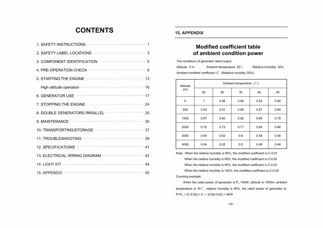
The conditions of generator rated output:
Altitude: 0 m Ambient temperature: 25 Relative humidity: 30%
Ambient modified coefficient: C (Relative humidity 30%)
Note: When the relative humidity is 60%, the modified coefficient is C-0.01
When the relative humidity is 80%, the modified coefficient is C-0.02
When the relative humidity is 90%, the modified coefficient is C-0.03
When the relative humidity is 100%, the modified coefficient is C-0.04
Counting example:
When the rated power of generator is P =5KW, altitude is 1000m, ambient N
temperature is 35 , relative humidity is 80%, the rated power of generator is:
P=P (C-0.02) = 5 (0.82-0.02) = 4KWN
Modified coefficient table of ambient condition power
Ambient temperature ( )Altitude
(m)
0
500
1000
2000
3000
4000
25
1
0.93
0.87
0.75
0.64
0.54
30
0.98
0.91
0.85
0.73
0.62
0.52
35
0.96
0.89
0.82
0.71
0.6
0.5
40
0.93
0.87
0.80
0.69
0.58
0.48
45
0.90
0.84
0.78
0.66
0.56
0.46
15. APPENDIX
- -
1. SAFETY INSTRUCTIONS
2. SAFETY LABEL LOCATIONS
3. COMPONENT IDENTIFICATION
4. PRE-OPERATION CHECK
5. STARTING THE ENGINE
High altitude operation
6. GENERATOR USE
7. STOPPING THE ENGINE
8. DOUBLE GENERATORS PARALLEL
9. MAINTENANCE
10. TRANSPORTING/STORAGE
11. TROUBLESHOOTING
12. SPECIFICATIONS
13. ELECTRICAL WIRING DIAGRAM
14. LIGHT KIT
15. APPENDIX
CONTENTS
1
3
5
9
13
16
17
24
26
30
37
39
41
42
44
45
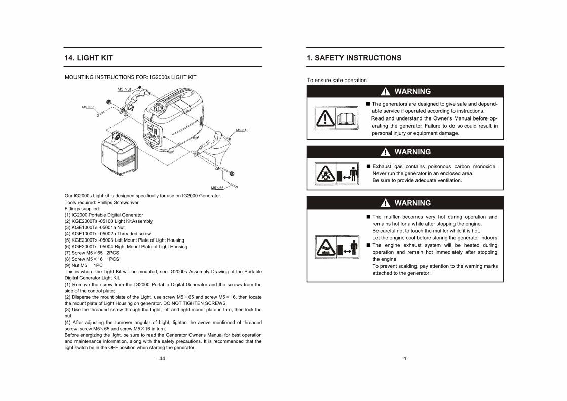
14. LIGHT KIT
Our IG2000s Light kit is designed specifically for use on IG2000 Generator.
Tools required: Phillips Screwdriver
Fittings supplied:
(1) IG2000 Portable Digital Generator
(2) KGE2000Tsi-05100 Light Kit Assembly
(3) KGE1000Tsi-05001a Nut
(4) KGE1000Tsi-05002a Threaded screw
(5) KGE2000Tsi-05003 Left Mount Plate of Light Housing
(6) KGE2000Tsi-05004 Right Mount Plate of Light Housing
(7) Screw M5 65 2PCS
(8) Screw M5 16 1PCS
(9) Nut M5 1PC
This is where the Light Kit will be mounted, see IG2000s Assembly Drawing of the Portable
Digital Generator Light Kit.
(1) Remove the screw from the IG2000 Portable Digital Generator and the screws from the
side of the control plate;
(2) Disperse the mount plate of the Light, use screw M5 65 and screw M5 16, then locate
the mount plate of Light Housing on generator. DO NOT TIGHTEN SCREWS.
(3) Use the threaded screw through the Light, left and right mount plate in turn, then lock the
nut.
(4) After adjusting the turnover angular of Light, tighten the avove mentioned of threaded
screw, screw M5 65 and screw M5 16 in turn.
Before energizing the light, be sure to read the Generator Owner's Manual for best operation
and maintenance information, along with the safety precautions. It is recommended that the
light switch be in the OFF position when starting the generator.
MOUNTING INSTRUCTIONS FOR: IG2000s LIGHT KIT
M5 65
M5 65
M5 16
- -
1. SAFETY INSTRUCTIONS
To ensure safe operation
WARNING
The generators are designed to give safe and depend-
Read and understand the Owner's Manual before op-
erating the generator. Failure to do so could result in
WARNING
WARNING
able service if operated according to instructions.
personal injury or equipment damage.
Exhaust gas contains poisonous carbon monoxide.
Never run the generator in an enclosed area.
Be sure to provide adequate ventilation.
The muffler becomes very hot during operation and
remains hot for a while after stopping the engine.
Be careful not to touch the muffler while it is hot.
Let the engine cool before storing the generator indoors.
The engine exhaust system will be heated during
operation and remain hot immediately after stopping
the engine.
To prevent scalding, pay attention to the warning marks
attached to the generator.
M5 Nut
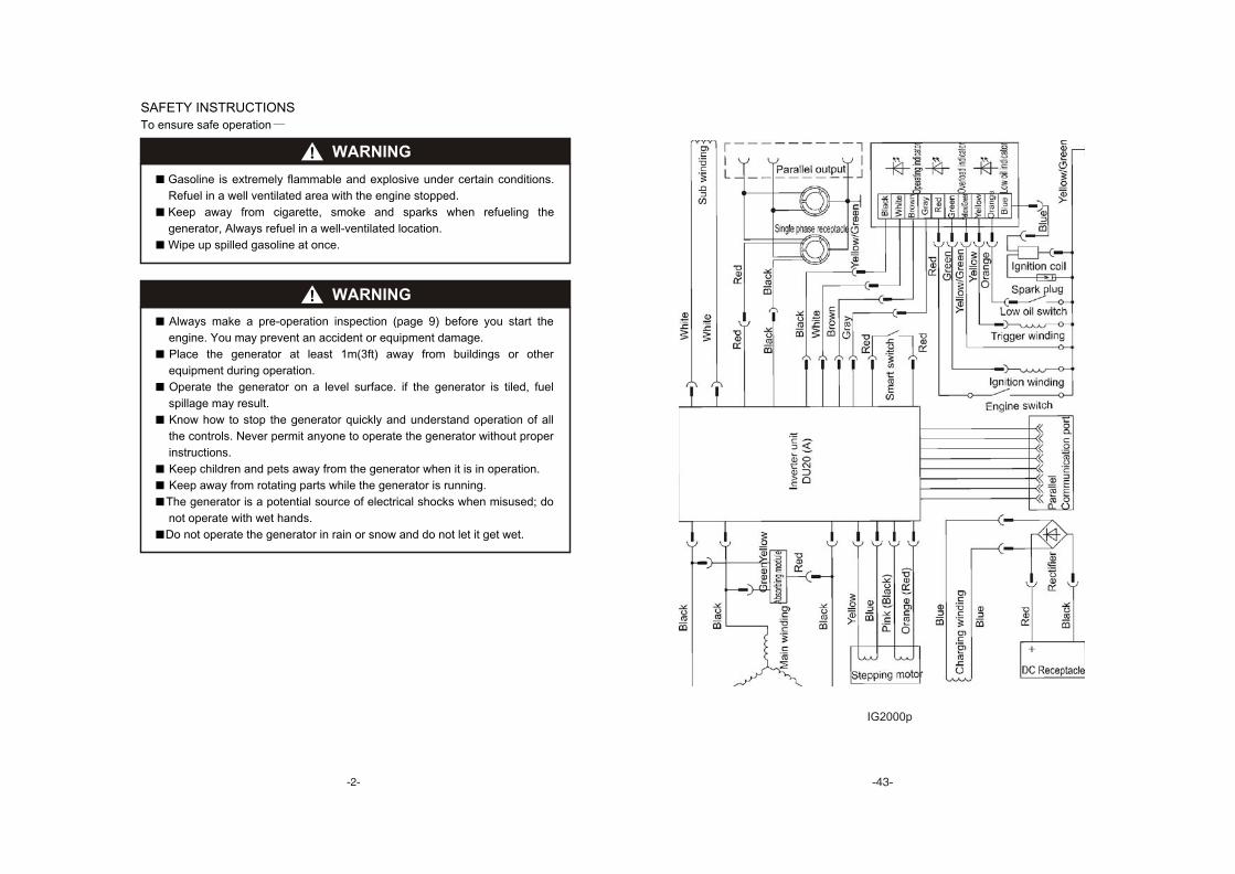
IG2000p
- -
WARNING
SAFETY INSTRUCTIONS
To ensure safe operation
Gasoline is extremely flammable and explosive under certain conditions.
Refuel in a well ventilated area with the engine stopped.
Keep away from cigarette, smoke and sparks when refueling the
generator, Always refuel in a well-ventilated location.
Wipe up spilled gasoline at once.
WARNING
Always make a pre-operation inspection (page 9) before you start the
engine. You may prevent an accident or equipment damage.
Place the generator at least 1m(3ft) away from buildings or other
equipment during operation.
Operate the generator on a level surface. if the generator is tiled, fuel
spillage may result.
Know how to stop the generator quickly and understand operation of all
the controls. Never permit anyone to operate the generator without proper
instructions.
Keep children and pets away from the generator when it is in operation.
Keep away from rotating parts while the generator is running.
The generator is a potential source of electrical shocks when misused; do
not operate with wet hands.
Do not operate the generator in rain or snow and do not let it get wet.
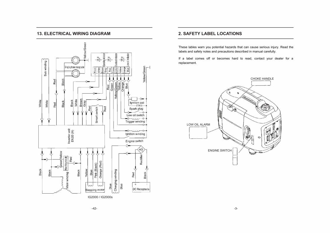
13. ELECTRICAL WIRING DIAGRAM
- -
IG2000 / IG2000s
2. SAFETY LABEL LOCATIONS
These lables warn you potential hazards that can cause serious injury. Read the
labels and safety notes and precautions described in manual carefully.
If a label comes off or becomes hard to read, contact your dealer for a
replacement.
CHOKE HANDLE
LOW OIL ALARM
ENGINE SWITCH
- -
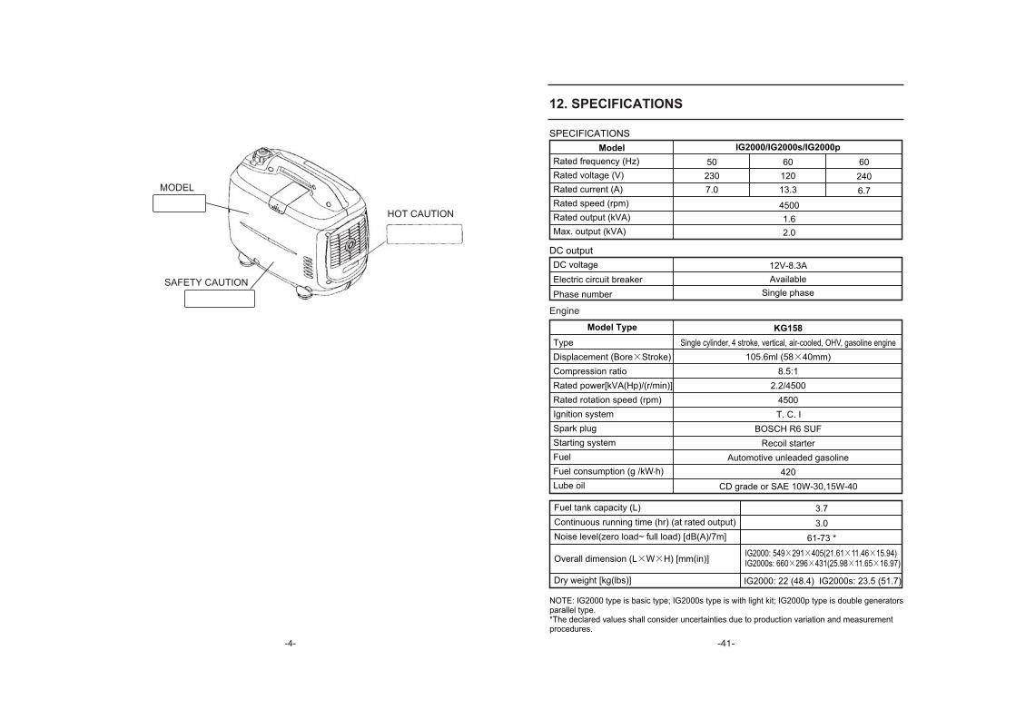
SAFETY CAUTION
MODEL
HOT CAUTION
12. SPECIFICATIONS
DC output
DC voltage
Electric circuit breaker
Phase number
12V-8.3A
Available
Single phase
SPECIFICATIONS
Model IG2000/IG2000s/IG2000p
Rated frequency (Hz)
Rated voltage (V)
Rated current (A)
Rated speed (rpm)
Rated output (kVA)
Max. output (kVA)
50
230
7.0
4500
1.6
2.0
60
240
6.7
Engine
Model Type KG158
Type
Displacement (Bore Stroke)
Compression ratio
Rated power[kVA(Hp)/(r/min)]
Rated rotation speed (rpm)
Ignition system
Spark plug
Starting system
Fuel
.Fuel consumption (g /kW h)
Lube oil
Single cylinder, 4 stroke, vertical, air-cooled, OHV, gasoline engine
105.6ml (58 40mm)
8.5:1
2.2/4500
4500
T. C. I
BOSCH R6 SUF
Recoil starter
Automotive unleaded gasoline
420
CD grade or SAE 10W-30,15W-40
Fuel tank capacity (L)
Continuous running time (hr) (at rated output)
Noise level(zero load~ full load) [dB(A)/7m]
3.7
3.0
61-73 *
Dry weight [kg(lbs)] IG2000: 22 (48.4) IG2000s: 23.5 (51.7)
IG2000: 549 291 405(21.61 11.46 15.94)IG2000s: 660 296 431(25.98 11.65 16.97)
60
120
13.3
Overall dimension (L W H) [mm(in)]
NOTE: IG2000 type is basic type; IG2000s type is with light kit; IG2000p type is double generatorsparallel type.*The declared values shall consider uncertainties due to production variation and measurement procedures.
No electricity at the DC receptacle:
Appliance does not operate:
Is the output indicator light ON?
Is the overload in-
dicator light ON?
Take the generator to an
authorized dealer.
Check the electrical appli-
ance or equipment for any
defects.
Take the generator to an
authorized dealer.
Replace the electrical
appliance or equipment
Take the electrical appli-
ance or equipment to an
electrical shop for repair
Stop and restart the engine.
Take the generator to an
authorized dealer.
Turn the DC circuit protector on.Is DC circuit protect on? NO
YES
DEFECTS
NO DEFECTS
NO
NO
YES
YES
- -
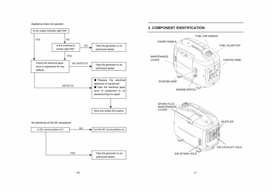
3. COMPONENT IDENTIFICATION
ENGINE SWITCH
FUEL CAP HANDLE
CHOKE HANDLE
FUEL FILLER CAP
MAINTENANCE
COVER CONTROL PANEL
STARTER GRIP
SPARK PLUGMAINTENANCECOVER
MUFFLER
AIR EXHAUAT HOLE
AIR INTAKE HOLE
11. TROUBLESHOOTING
To check:
1) Remove the spark plug cap and clean
any dirt from around the spark plug.
2) Remove the spark plug and install the
spark plug in the plug cap.
3) Set the plug side electrode on the cylinder
head to ground.
4) Pull the recoil starter, sparks should jump
across the gap.
When the engine will not start:
Is there fuel in the tank? NO
Refuel the fuel tank
YES
Is the engine switch on? Turn the engine switch on.
Is the enough oil in the engine? Add the recommended oil.
Is there a spark from
the spark plug?
Replace the
spark plug.
Take the generator to an
authorized dealer.
Still no
spark
YES
YES
NO
NO
NO
Be sure there is no spilled
fuel around the spark plug.
Spilled fuel may ignite.
WARNING
If the engine still does not
start, take the generator to an
authorized dealer.
- -
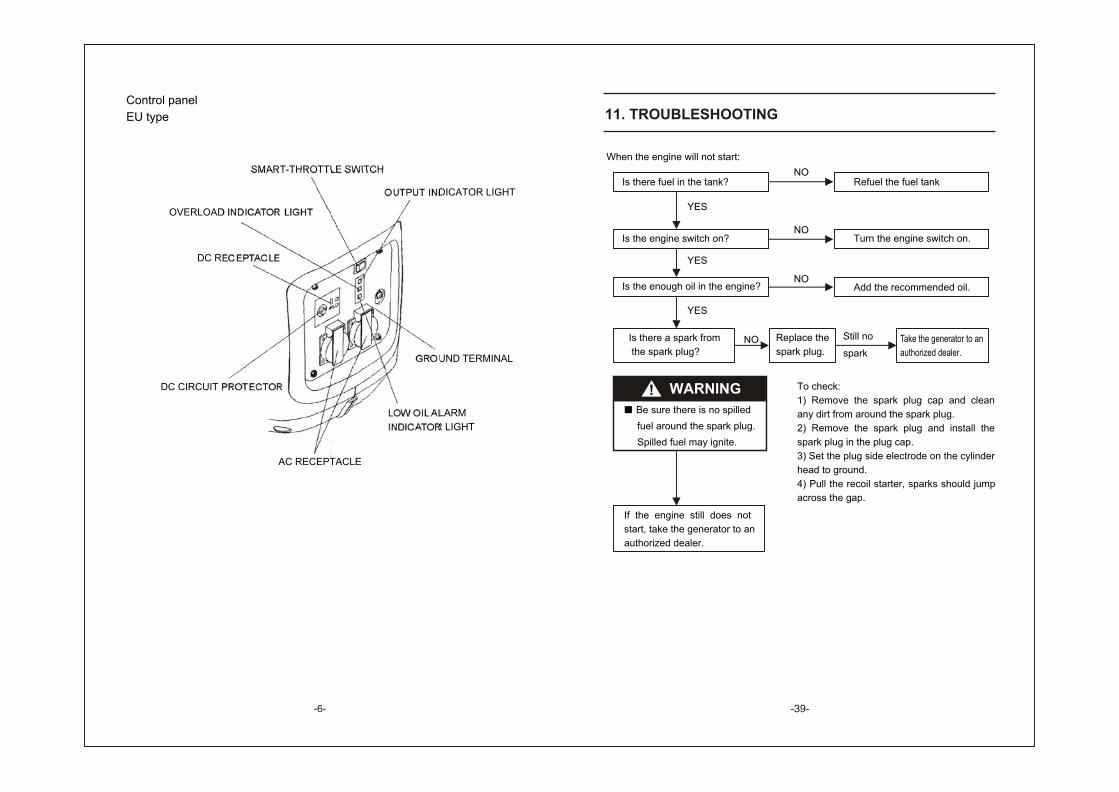
Control panel
EU type
LOW OIL ALARM
INDICATOR LIGHT
SMART-THROTTLE SWITCH
OUTPUT INDICATOR LIGHT
OVERLOAD INDICATOR LIGHT
DC RECEPTACLE
GROUND TERMINAL
DC CIRCUIT PROTECTOR
AC RECEPTACLE
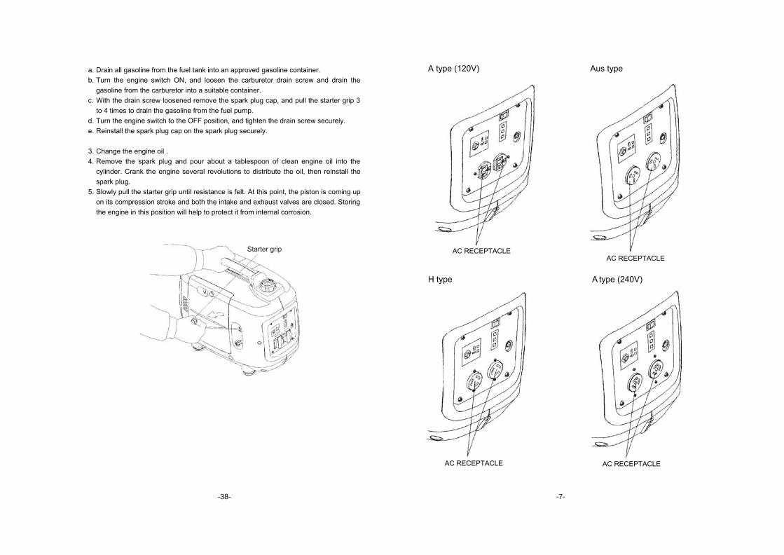
a. Drain all gasoline from the fuel tank into an approved gasoline container.
b. Turn the engine switch ON, and loosen the carburetor drain screw and drain the
gasoline from the carburetor into a suitable container.
c. With the drain screw loosened remove the spark plug cap, and pull the starter grip 3
to 4 times to drain the gasoline from the fuel pump.
d. Turn the engine switch to the OFF position, and tighten the drain screw securely.
e. Reinstall the spark plug cap on the spark plug securely.
3. Change the engine oil .
4. Remove the spark plug and pour about a tablespoon of clean engine oil into the
cylinder. Crank the engine several revolutions to distribute the oil, then reinstall the
spark plug.
5. Slowly pull the starter grip until resistance is felt. At this point, the piston is coming up
on its compression stroke and both the intake and exhaust valves are closed. Storing
the engine in this position will help to protect it from internal corrosion.
Starter grip
- -
A type (120V) Aus type
H type A type (240V)
AC RECEPTACLE AC RECEPTACLE
AC RECEPTACLEAC RECEPTACLE
10. TRANSPORTING STORAGE
To prevent fuel spillage when transporting or during temporary storage, the generator
should be secured upright in its normal operating position, with the engine switch OFF.
The fuel cap vent lever is turned counterclockwise to the OFF position.
Allow the engine to cool well before turning the fuel cap vent lever to the OFF position.
WARNING
When transporting the generator:
Do not overfill the tank (there should be no fuel in the filler neck).
Do not operate the generator while it is on a vehicle. Take the generator off the
vehicle and use it in a well ventilated place.
Avoid a place exposed to direct sunlight when putting the generator on a
vehicle. If the generator is left in an enclosed vehicle for many hours, high
temperature inside the vehicle could cause fuel to vaporize resulting in a
possible explosion.
Do not drive on a rough road for an extended period with the generator on
board. If you must transport the generator on board. If you must transport the
generator on a rough road, drain the fuel from the generator beforehand.
Before storing the unit for an extended period:
1. Be sure the storage area is free of excessive humidity and dust.
2. Drain the fuel.
WARNING
Gasoline is extremely flammable and explosive under certain conditions.
Do not smoke or allow flames or sparks in the area.
SCREW DRIVER
- -
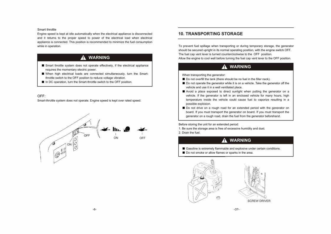
Smart throttle
Engine speed is kept at idle automatically when the electrical appliance is disconnected
and it returns to the proper speed to power of the electrical load when electrical
appliance is connected. This position is recommended to minimize the fuel consumption
while in operation.
WARNING
Smart throttle system does not operate effectively, if the electrical appliance
requires the momentary electric power.
When high electrical loads are connected simultaneously, turn the Smart-
throttle switch to the OFF position to reduce voltage vibration.
In DC operation, turn the Smart-throttle switch to the OFF position.
OFF:Smart-throttle system does not operate. Engine speed is kept over rated speed.
ONOFF
OFF
ON
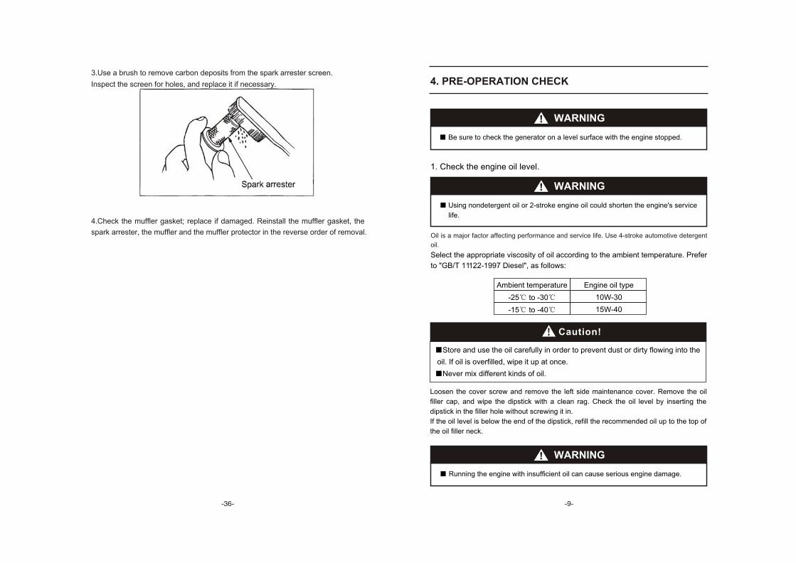
3.Use a brush to remove carbon deposits from the spark arrester screen.
Inspect the screen for holes, and replace it if necessary.
4.Check the muffler gasket; replace if damaged. Reinstall the muffler gasket, the
spark arrester, the muffler and the muffler protector in the reverse order of removal.
4. PRE-OPERATION CHECK
WARNING
Loosen the cover screw and remove the left side maintenance cover. Remove the oil
filler cap, and wipe the dipstick with a clean rag. Check the oil level by inserting the
dipstick in the filler hole without screwing it in.
If the oil level is below the end of the dipstick, refill the recommended oil up to the top of
the oil filler neck.
1. Check the engine oil level.
WARNING
Using nondetergent oil or 2-stroke engine oil could shorten the engine's service
life.
Running the engine with insufficient oil can cause serious engine damage.
Be sure to check the generator on a level surface with the engine stopped.
WARNING
Caution!
Store and use the oil carefully in order to prevent dust or dirty flowing into the
oil. If oil is overfilled, wipe it up at once.
Never mix different kinds of oil.
Oil is a major factor affecting performance and service life. Use 4-stroke automotive detergent
oil.
Select the appropriate viscosity of oil according to the ambient temperature. Prefer
to "GB/T 11122-1997 Diesel", as follows:
Ambient temperature
-25 to -30
-15 to -40
Engine oil type
10W-30
15W-40
4.SPARK ARRESTER MAINTENANCE(Equipped type only)
If the generator has been running, the muffler will be
very hot. Allow it to cool before proceeding.
The spark arrester must be serviced every 100 hours
to maintain its efficiency.
1.Remove the four 5 mm screws, and remove the muffler protector.
2.Remove the there 6 mm bolts, and remove the muffler, the spark arrester and the
muffler gasket
WARNING
CAUTION
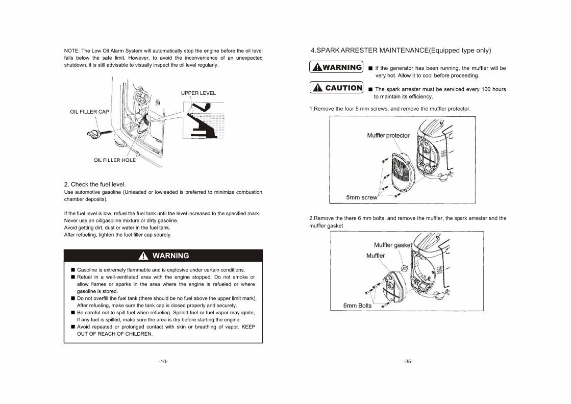
NOTE: The Low Oil Alarm System will automatically stop the engine before the oil level
falls below the safe limit. However, to avoid the inconvenience of an unexpected
shutdown, it is still advisable to visually inspect the oil level regularly.
OIL FILLER HOLE
WARNING
Gasoline is extremely flammable and is explosive under certain conditions.
Refuel in a well-ventilated area with the engine stopped. Do not smoke or
allow flames or sparks in the area where the engine is refueled or where
gasoline is stored.
Do not overfill the fuel tank (there should be no fuel above the upper limit mark).
After refueling, make sure the tank cap is closed properly and securely.
Be careful not to spill fuel when refueling. Spilled fuel or fuel vapor may ignite,
If any fuel is spilled, make sure the area is dry before starting the engine.
Avoid repeated or prolonged contact with skin or breathing of vapor. KEEP
OUT OF REACH OF CHILDREN.
2. Check the fuel level.Use automotive gasoline (Unleaded or lowleaded is preferred to minimize combustion
chamber deposits).
If the fuel level is low, refuel the fuel tank until the level increased to the specified mark.
Never use an oil/gasoline mixture or dirty gasoline.
Avoid getting dirt, dust or water in the fuel tank.
After refueling, tighten the fuel filler cap seurely.
UPPER LEVEL
OIL FILLER CAP
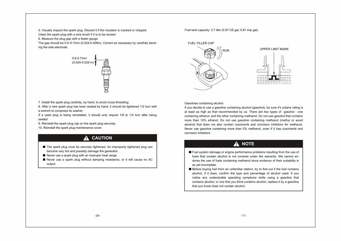
5. Visually inspect the spark plug. Discard it if the insulator is cracked or chipped.
Clean the spark plug with a wire brush if it is to be reused.
6. Measure the plug gap with a feeler gauge.
The gap should be 0.6~0.7mm (0.024-0.028in). Correct as necessary by carefully bend-
ing the side electrode.
7. Install the spark plug carefully, by hand, to avoid cross-threading.
8. After a new spark plug has been seated by hand, it should be tightened 1/2 turn with
a wrench to compress its washer.
If a used plug is being reinstalled, it should only require 1/8 to 1/4 turn after being
seated.
9. Reinstall the spark plug cap on the spark plug securely.
10. Reinstall the spark plug maintenance cover.
CAUTION
The spark plug must be securely tightened. An improperly tightened plug can
become very hot and possibly damage the generator.
Never use a spark plug with an improper heat range.
Never use a spark plug without damping resistance, or it will cause no AC
output.
0.6-0.7mm
(0.024-0.028 in)
Gasolines containing alcohol
If you decide to use a gasoline containing alcohol (gasohol), be sure it's octane rating is
at least as high as that recommended by us. There are two types of gasohol : one
containing ethanol, and the other containing methanol. Do not use gasohol that contains
more than 10% ethanol. Do not use gasoline containing methanol (methyl or wood
alcohol) that does not also contain cosolvents and corrosion inhibitors for methanol.
Never use gasoline containing more than 5% methanol, even if it has cosolvents and
corrosion inhibitors.
Fuel tank capacity: 3.7 liter (0.97 US gal, 0.81 lmp gal)
UPPER LIMIT MARK
NOTE
Fuel system damage or engine performance problems resulting from the use of
fuels that contain alcohol is not covered under the warranty. We cannot en-
dorse the use of fuels containing methanol since evidence of their suitability is
as yet incomplete.
Before buying fuel from an unfamiliar station, try to find out if the fuel contains
alcohol, if it does, confirm the type and percentage of alcohol used. If you
notice any undersirable operating symptoms while using a gasoline that
contains alcohol, or one that you think contains alcohol, replace it by a gasoline
that you know does not contain alcohol.
FUEL FILLER CAP
RUN
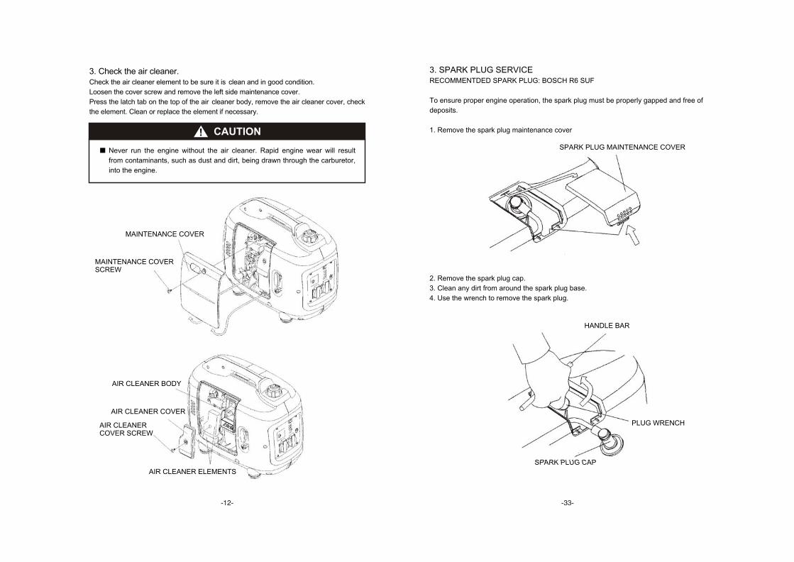
3. SPARK PLUG SERVICERECOMMENTDED SPARK PLUG: BOSCH R6 SUF
To ensure proper engine operation, the spark plug must be properly gapped and free of
deposits.
1. Remove the spark plug maintenance cover
2. Remove the spark plug cap.
3. Clean any dirt from around the spark plug base.
4. Use the wrench to remove the spark plug.
SPARK PLUG MAINTENANCE COVER
SPARK PLUG CAP
HANDLE BAR
PLUG WRENCH
3. Check the air cleaner.Check the air cleaner element to be sure it is clean and in good condition.
Loosen the cover screw and remove the left side maintenance cover.
Press the latch tab on the top of the air cleaner body, remove the air cleaner cover, check
the element. Clean or replace the element if necessary.
CAUTION
Never run the engine without the air cleaner. Rapid engine wear will result
from contaminants, such as dust and dirt, being drawn through the carburetor,
into the engine.
AIR CLEANER ELEMENTS
AIR CLEANER BODY
AIR CLEANER COVER
AIR CLEANERCOVER SCREW
MAINTENANCE COVER
MAINTENANCE COVERSCREW
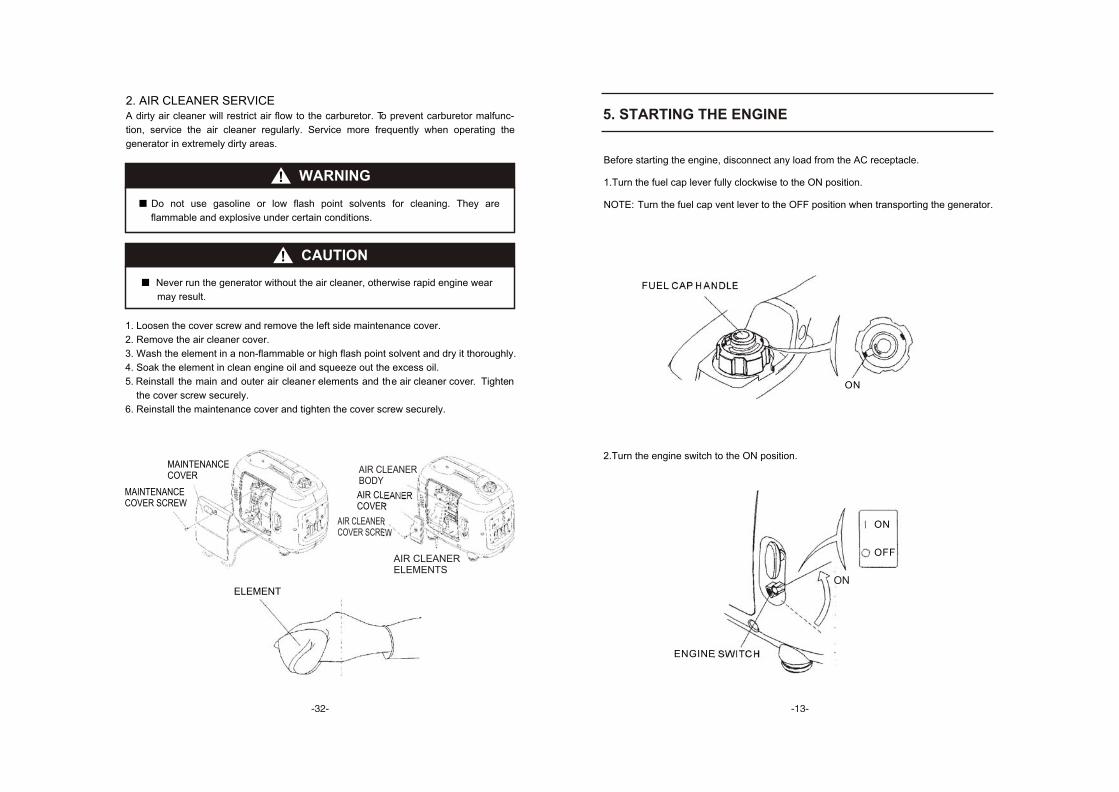
2. AIR CLEANER SERVICEA dirty air cleaner will restrict air flow to the carburetor. To prevent carburetor malfunc-
tion, service the air cleaner regularly. Service more frequently when operating the
generator in extremely dirty areas.
1. Loosen the cover screw and remove the left side maintenance cover.
2. Remove the air cleaner cover.
3. Wash the element in a non-flammable or high flash point solvent and dry it thoroughly.
4. Soak the element in clean engine oil and squeeze out the excess oil.
5. Reinstall the main and outer ai r cleane r element s an d th e a ir cleane r cove r . Tighte n
the cover screw securely.
6. Reinstall the maintenance cover and tighten the cover screw securely.
WARNING
Do not use gasoline or low flash point solvents for cleaning. They are
flammable and explosive under certain conditions.
CAUTION
Never run the generator without the air cleaner, otherwise rapid engine wear
may result.
ELEMENT
AIR CLEANER COVER SCREW
AIR CLEANER COVER
MAINTENANCE COVER SCREW
MAINTENANCECOVER
AIR CLEANERBODY
AIR CLEANER ELEMENTS
5. STARTING THE ENGINE
Before starting the engine, disconnect any load from the AC receptacle.
1.Turn the fuel cap lever fully clockwise to the ON position.
NOTE: Turn the fuel cap vent lever to the OFF position when transporting the generator.
FUEL CAP HANDLE
ENGINE SWITCH
2.Turn the engine switch to the ON position.
ON
ON
OFF
ON
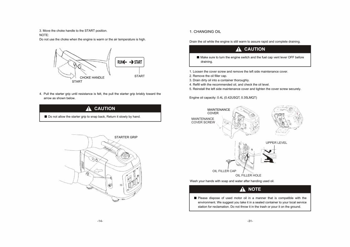
1. CHANGING OIL
Drain the oil while the engine is still warm to assure rapid and complete draining.
1. Loosen the cover screw and remove the left side maintenance cover.
2. Remove the oil filler cap.
3. Drain dirty oil into a container thoroughly.
4. Refill with the recommended oil, and check the oil level.
5. Reinstall the left side maintenance cover and tighten the cover screw securely.
Engine oil capacity: 0.4L (0.42USQT, 0.35LMQT)
Make sure to turn the engine switch and the fuel cap vent lever OFF before
draining.
CAUTION
Wash your hands with soap and water after handing used oil.
NOTE
Please dispose of used motor oil in a manner that is compatible with the
environment. We suggest you take it in a sealed container to your local service
station for reclamation. Do not throw it in the trash or pour it on the ground.
OIL FILLER CAP
OIL FILLER HOLE
UPPER LEVEL
MAINTENANCE COVER
MAINTENANCECOVER SCREW
4. Pull the starter grip until resistance is felt, the pull the starter grip briskly toward the
arrow as shown below.
3. Move the choke handle to the START position.
NOTE:
Do not use the choke when the engine is warm or the air temperature is high.
CAUTION
Do not allow the starter grip to snap back, Return it slowly by hand.
STARTER GRIP
CHOKE HANDLE
START
START
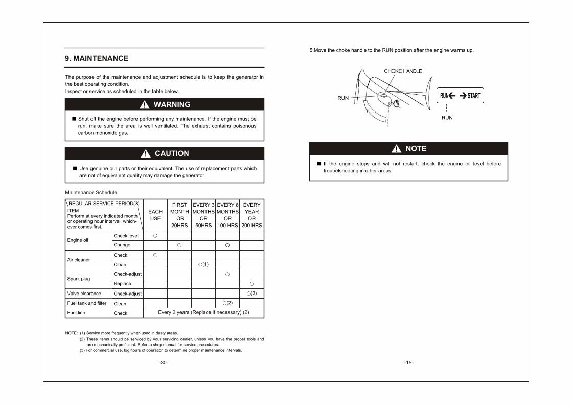
9. MAINTENANCE
The purpose of the maintenance and adjustment schedule is to keep the generator in
the best operating condition.
Inspect or service as scheduled in the table below.
WARNING
Shut off the engine before performing any maintenance. If the engine must be
run, make sure the area is well ventilated. The exhaust contains poisonous
carbon monoxide gas.
CAUTION
Use genuine our parts or their equivalent. The use of replacement parts which
are not of equivalent quality may damage the generator.
NOTE: (1) Service more frequently when used in dusty areas.
(2) These items should be serviced by your servicing dealer, unless you have the proper tools and
are mechanically proficient. Refer to shop manual for service procedures.
(3) For commercial use, log hours of operation to determine proper maintenance intervals.
ITEMPerform at every indicated monthor operating hour interval, which-ever comes first.
REGULAR SERVICE PERIOD(3)
Fuel line Check
Check level
Change
Check
Clean
Check-adjust
Replace
Check-adjust
Clean
Engine oil
Air cleaner
Spark plug
Valve clearance
Fuel tank and filter
EVERY
YEAR
OR
200 HRS
EACH
USE
FIRST
MONTH
OR
20HRS
EVERY 3
MONTHS
OR
50HRS
EVERY 6
MONTHS
OR
100 HRS
(1)
(2)
(2)
Every 2 years (Replace if necessary) (2)
Maintenance Schedule
5.Move the choke handle to the RUN position after the engine warms up.
NOTE
If the engine stops and will not restart, check the engine oil level before
troubelshooting in other areas.
CHOKE HANDLE
WARNING:
The special parallel cable for our IG2000p is only applicable to the parallel operation
of two IG2000p generators. It can not be used for paralleling three or above three
generators.
Be sure only use parallel output cable for parallel running. Other cables are
forbidden.
While connecting the generator and electrical appliance with the parallel output
cable, do carefully and safely insert the plug into the receptacle.
While operating parallel, only output through the receptacle on the parallel cable
wire, don't use the receptacle on the control panel of the generator.
Make sure insert the plugs on the parallel cable wire to the related proper
receptacles.
Make sure the output is directly from the receptacles on the parallel output cable
while parallel running, instead of the receptacles on the generator control panels.
Don't disconnect the PARALLEL I/O special connection cable and parallel output
cable during the parallel running, connect the PARALLEL I/O special connection
cable before start the engine, and then connect the parallel output cable. You can
disconnect the PARALLEL I/O special connection cable and parallel output cable
only after stopping the generator.
If the parallel output cable is still connected, cut off the current output after either
generator was shut off.
Don't use the parallel output cable and parallel connection cable while operating two
generator separately.
Don't connect the parallel cable wire while the two generator running singly.
Read IG2000p operation manual before using the generator.
High altitude operation
At high altitude, the standard carburetor air-fuel mixture will be excessively rich.
Performance will decrease, and fuel consumption will increase.
High altitude performance can be improved by installing a smaller diameter main fuel jet
in the carburetor and readjusting the pilot screws. If you always operate the generator at
altitudes higher than 1,500 m (5,000 feet) above sea level, have your authorized dealer
perform these carburetor modifications.
Even with suitable carburetor jetting, engine horsepower will decrease approximately
3.5% for each 300m (1,000 feet) increase in altitude. The affect of altitude on the
horsepower will be greater than this if no carburetor modification is made.
CAUTION
Operation of the generator at an altitude lower than the carburetor is jetted for
may result in reduced performance, overheating, and serious engine damage
caused by an excessively lean air/fuel mixture.
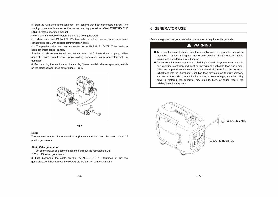
5. Start the twin generators (engines) and confirm that both generators started. The
starting procedure is same as the normal starting procedure. (See"STARTING THE
ENGINE"of the operation manual.)
Note: Confirm the bellows before starting the both generators.
(1). Make sure two PARALLEL I/O terminals on either control panel have been
connected reliably with special communication cable.
(2). The parallel cable has been connected to the PARALLEL OUTPUT terminals on
each generator control panels.
If either of above mentioned two connections hasn't been done properly, either
generator won't output power while starting generators, even generators will be
damaged.
6. Securely plug the electrical appliance plug into parallel cable receptacle , switch
on the electrical appliance power supply. Fig. 5
Fig. 5
Note:
The required output of the electrical appliance cannot exceed the rated output of
parallel generators.
Shut off the generators:
1. Turn off the power of electrical appliance, pull out the receptacle plug.
2. Turn off the two generators.
3. First disconnect the cable on the PARALLEL OUTPUT terminals of the two
generators. And then remove the PARALLEL I/O parallel connection cable.
6. GENERATOR USE
WARNING
To prevent electrical shock from faulty appliances, the generator should be
grounded. Connect a length of heavy wire between the generator's ground
teminal and an external ground source.
Connections for standby power to a building's electrical system must be made
by a qualified electrician and must comply with all applicable laws and electri-
cal codes. Improper connections can allow electrical current from the generator
to backfeed into the utility lines. Such backfeed may electrocute utility company
workers or others who contact the lines during a power outage, and when utility
power is restored, the generator may explode, burn, or cause fires in the
building's electrical system.
Be sure to ground the generator when the connected equipment is grounded.
GROUND MARK
GROUND TERMINAL
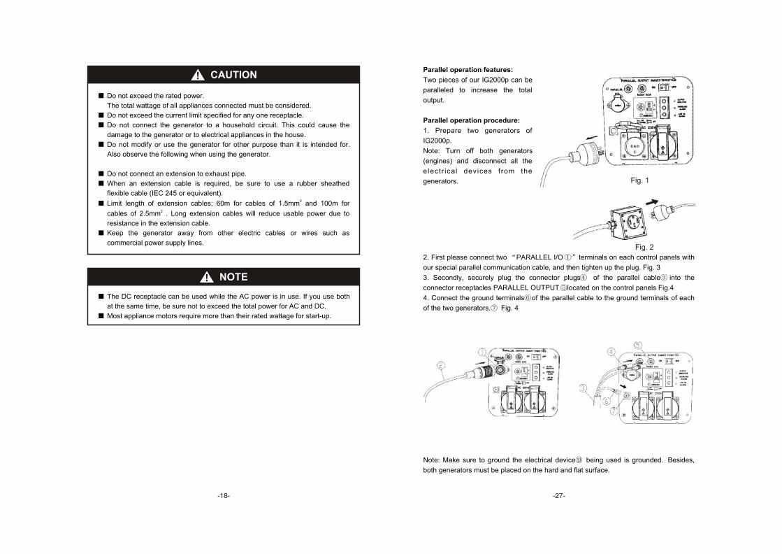
Fig. 1
Fig. 2
2. First please connect two PARALLEL I/O terminals on each control panels with
our special parallel communication cable, and then tighten up the plug. Fig. 3
3. Secondly, securely plug the connector plugs of the parallel cable into the
connector receptacles PARALLEL OUTPUT located on the control panels Fig.4
4. Connect the ground terminals of the parallel cable to the ground terminals of each
of the two generators. Fig. 4
Note: Make sure to ground the electrical device being used is grounded. Besides,
both generators must be placed on the hard and flat surface.
Parallel operation features:
Two pieces of our IG2000p can be
paralleled to increase the total
output.
Parallel operation procedure:
1. Prepare two generators of
IG2000p.
Note: Turn off both generators
(engines) and disconnect all the
e lectr ica l devices f rom the
generators.
CAUTION
Do not exceed the rated power.
The total wattage of all appliances connected must be considered.
Do not exceed the current limit specified for any one receptacle.
Do not connect the generator to a household circuit. This could cause the
damage to the generator or to electrical appliances in the house.
Do not modify or use the generator for other purpose than it is intended for.
Also observe the following when using the generator.
Do not connect an extension to exhaust pipe.
When an extension cable is required, be sure to use a rubber sheathed
flexible cable (IEC 245 or equivalent).2Limit length of extension cables; 60m for cables of 1.5mm and 100m for
2cables of 2.5mm . Long extension cables will reduce usable power due to
resistance in the extension cable.
Keep the generator away from other electric cables or wires such as
commercial power supply lines.
NOTE
The DC receptacle can be used while the AC power is in use. If you use both
at the same time, be sure not to exceed the total power for AC and DC.
Most appliance motors require more than their rated wattage for start-up.
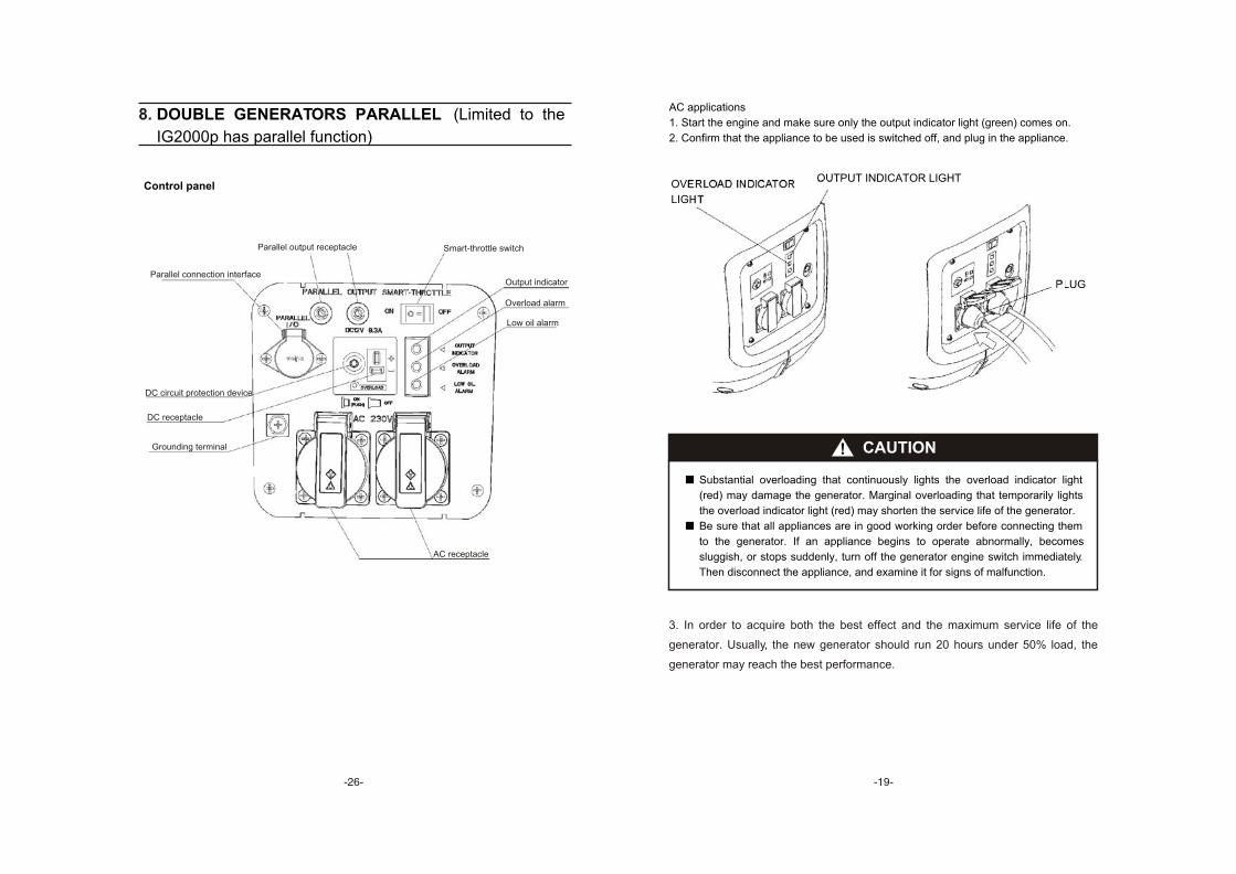
8. DOUBLE GENERATORS PARALLEL (Limited to the
IG2000p has parallel function)
Control panel
Parallel output receptacle
Parallel connection interface
Smart-throttle switch
Output indicator
Overload alarm
Low oil alarm
AC receptacle
Grounding terminal
DC receptacle
DC circuit protection device
AC applications
1. Start the engine and make sure only the output indicator light (green) comes on.
2. Confirm that the appliance to be used is switched off, and plug in the appliance.
PLUG
CAUTION
Substantial overloading that continuously lights the overload indicator light
(red) may damage the generator. Marginal overloading that temporarily lights
the overload indicator light (red) may shorten the service life of the generator.
Be sure that all appliances are in good working order before connecting them
to the generator. If an appliance begins to operate abnormally, becomes
sluggish, or stops suddenly, turn off the generator engine switch immediately.
Then disconnect the appliance, and examine it for signs of malfunction.
OUTPUT INDICATOR LIGHTOVERLOAD INDICATOR
LIGHT
3. In order to acquire both the best effect and the maximum service life of the
generator. Usually, the new generator should run 20 hours under 50% load, the
generator may reach the best performance.
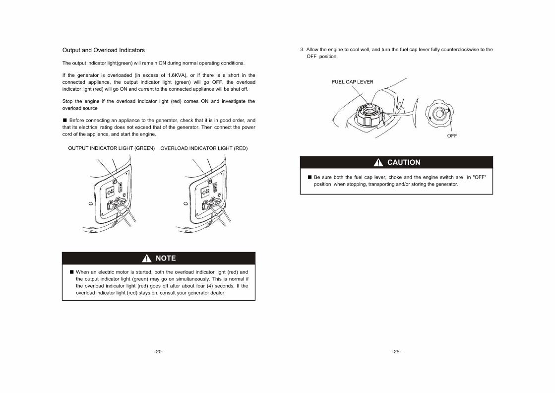
3. Allow the engine to cool well, and turn the fuel cap lever fully counterclockwise to the
OFF position.
FUEL CAP LEVER
CAUTION
Be sure both the fuel cap lever, choke and the engine switch are in "OFF"
position when stopping, transporting and/or storing the generator.
OFF
Output and Overload Indicators
The output indicator light(green) will remain ON during normal operating conditions.
If the generator is overloaded (in excess of 1.6KVA), or if there is a short in the
connected appliance, the output indicator light (green) will go OFF, the overload
indicator light (red) will go ON and current to the connected appliance will be shut off.
Stop the engine if the overload indicator light (red) comes ON and investigate the
overload source
Before connecting an appliance to the generator, check that it is in good order, and
that its electrical rating does not exceed that of the generator. Then connect the power
cord of the appliance, and start the engine.
NOTE
When an electric motor is started, both the overload indicator light (red) and
the output indicator light (green) may go on simultaneously. This is normal if
the overload indicator light (red) goes off after about four (4) seconds. If the
overload indicator light (red) stays on, consult your generator dealer.
OUTPUT INDICATOR LIGHT (GREEN) OVERLOAD INDICATOR LIGHT (RED)
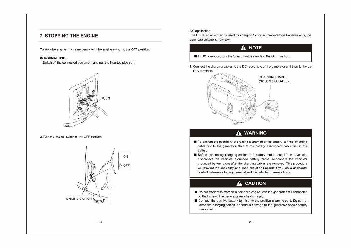
7. STOPPING THE ENGINE
To stop the engine in an emergency, turn the engine switch to the OFF position.
IN NORMAL USE:
1.Switch off the connected equipment and pull the inserted plug out.
2.Turn the engine switch to the OFF position
PLUG
ENGINE SWITCH
ON
OFF
OFF
DC application
The DC receptacle may be used for charging 12 volt automotive-type batteries only, the
zero load voltage is 15V-30V.
NOTE
In DC operation, turn the Smart-throttle switch to the OFF position.
1. Connect the charging cables to the DC receptacle of the generator and then to the ba-
ttery terminals.
WARNING
To prevent the possibility of creating a spark near the battery, connect charging
cable first to the generator, then to the battery. Disconnect cable first at the
battery.
Before connecting charging cables to a battery that is installed in a vehicle,
disconnect the vehicles grounded battery cable. Reconnect the vehicle's
grounded battery cable after the charging cables are removed. This procedure
will prevent the possibility of a short circuit and sparks if you make accidental
contact between a battery terminal and the vehicle's frame or body.
CAUTION
Do not attempt to start an automobile engine with the generator still connected
to the battery. The generator may be damaged.
Connect the positive battery terminal to the positive charging cord. Do not re-
verse the charging cables, or serious damage to the generator and/or battery
may occur.
CHARGING CABLE
(SOLD SEPARATELY)
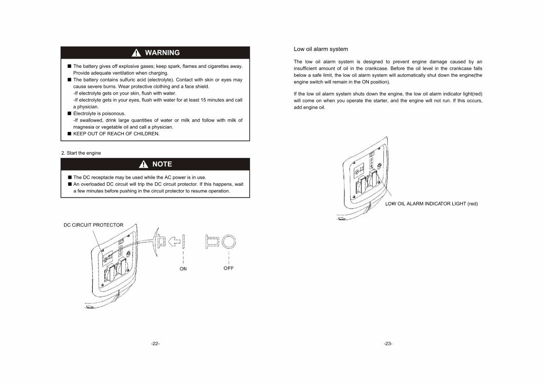
Low oil alarm system
The low oil alarm system is designed to prevent engine damage caused by an
insufficient amount of oil in the crankcase. Before the oil level in the crankcase falls
below a safe limit, the low oil alarm system will automatically shut down the engine(the
engine switch will remain in the ON position).
If the low oil alarm system shuts down the engine, the low oil alarm indicator light(red)
will come on when you operate the starter, and the engine will not run. If this occurs,
add engine oil.
LOW OIL ALARM INDICATOR LIGHT (red)
WARNING
The battery gives off explosive gases; keep spark, flames and cigarettes away.
Provide adequate ventilation when charging.
The battery contains sulfuric acid (electrolyte). Contact with skin or eyes may
cause severe burns. Wear protective clothing and a face shield.
-If electrolyte gets on your skin, flush with water.
-If electrolyte gets in your eyes, flush with water for at least 15 minutes and call
a physician.
Electrolyte is poisonous.
-If swallowed, drink large quantities of water or milk and follow with milk of
magnesia or vegetable oil and call a physician.
KEEP OUT OF REACH OF CHILDREN.
2. Start the engine
NOTE
The DC receptacle may be used while the AC power is in use.
An overloaded DC circuit will trip the DC circuit protector. If this happens, wait
a few minutes before pushing in the circuit protector to resume operation.
ON OFF
DC CIRCUIT PROTECTOR