
WSDOT Bridge Design Manual M 23-50 Chapter 5 Concrete ...
438
WSDOT Bridge Design Manual M 23-50.17 Page 5-i June 2017 5.0 General 5-1 5.1 Materials 5-2 5.1.1 Concrete 5-2 5.1.2 Reinforcing Steel 5-8 5.1.3 Prestressing Steel 5-12 5.1.4 Prestress Losses 5-19 5.1.5 Prestressing Anchorage Systems 5-23 5.1.6 Post-Tensioning Ducts 5-23 5.2 Design Considerations 5-24 5.2.1 Service and Fatigue Limit States 5-24 5.2.2 Strength-Limit State 5-25 5.2.3 Strut-and-Tie Model 5-29 5.2.4 Deflection and Camber 5-30 5.2.5 Construction Joints 5-32 5.2.6 Inspection Lighting and Access 5-33 5.3 Reinforced Concrete Box Girder Bridges 5-36 5.3.1 Box Girder Basic Geometries 5-36 5.3.2 Reinforcement 5-41 5.3.3 Crossbeam 5-49 5.3.4 End Diaphragm 5-52 5.3.5 Dead Load Deflection and Camber 5-55 5.3.6 Thermal Effects 5-55 5.3.7 Hinges 5-56 5.3.8 Drain Holes 5-56 5.4 Hinges and Inverted T-Beam Pier Caps 5-58 5.5 Bridge Widenings 5-61 5.5.1 Review of Existing Structures 5-61 5.5.2 Analysis and Design Criteria 5-62 5.5.3 Removing Portions of the Existing Structure 5-65 5.5.4 Attachment of Widening to Existing Structure 5-66 5.5.5 Expansion Joints 5-78 5.5.6 Possible Future Widening for Current Designs 5-79 5.5.7 Bridge Widening Falsework 5-79 5.5.8 Existing Bridge Widenings 5-79 5.6 Prestressed Concrete Girder Superstructures 5-80 5.6.1 WSDOT Standard Prestressed Concrete Girder Types 5-80 5.6.2 Design Criteria 5-83 5.6.3 Fabrication and Handling 5-95 5.6.4 Superstructure Optimization 5-99 5.6.5 Repair of Damaged Prestressed Concrete Girders at Fabrication 5-105 5.6.6 Repair of Damaged Prestressed Concrete Girders in Existing Bridges 5-106 5.6.7 Deck Girders 5-111 5.6.8 Prestressed Concrete Tub Girders 5-113 5.6.9 Prestressed Concrete Girder Checking Requirement 5-114 5.6.10 Review of Shop Plans for Pre-tensioned Girders 5-114 Chapter 5 Concrete Structures Contents
Transcript of WSDOT Bridge Design Manual M 23-50 Chapter 5 Concrete ...
WSDOT Bridge Design Manual M 23-50.17 Page 5-i June 2017
5.0 General . . . . . . . . . . . . . . . . . . . . . . . . . . . . . . . . . . . . . . . . . . . . . . . . . . . . . . . . . . . . . . . . .5-1
5.1 Materials . . . . . . . . . . . . . . . . . . . . . . . . . . . . . . . . . . . . . . . . . . . . . . . . . . . . . . . . . . . . . . . .5-25.1.1 Concrete . . . . . . . . . . . . . . . . . . . . . . . . . . . . . . . . . . . . . . . . . . . . . . . . . . . . . . . . . .5-25.1.2 Reinforcing Steel . . . . . . . . . . . . . . . . . . . . . . . . . . . . . . . . . . . . . . . . . . . . . . . . . . . .5-85.1.3 Prestressing Steel . . . . . . . . . . . . . . . . . . . . . . . . . . . . . . . . . . . . . . . . . . . . . . . . . . .5-125.1.4 Prestress Losses . . . . . . . . . . . . . . . . . . . . . . . . . . . . . . . . . . . . . . . . . . . . . . . . . . . .5-195.1.5 Prestressing Anchorage Systems . . . . . . . . . . . . . . . . . . . . . . . . . . . . . . . . . . . . . . . .5-235.1.6 Post-Tensioning Ducts . . . . . . . . . . . . . . . . . . . . . . . . . . . . . . . . . . . . . . . . . . . . . . .5-23
5.2 Design Considerations . . . . . . . . . . . . . . . . . . . . . . . . . . . . . . . . . . . . . . . . . . . . . . . . . . . .5-245.2.1 Service and Fatigue Limit States . . . . . . . . . . . . . . . . . . . . . . . . . . . . . . . . . . . . . . . .5-245.2.2 Strength-Limit State . . . . . . . . . . . . . . . . . . . . . . . . . . . . . . . . . . . . . . . . . . . . . . . . .5-255.2.3 Strut-and-Tie Model . . . . . . . . . . . . . . . . . . . . . . . . . . . . . . . . . . . . . . . . . . . . . . . . .5-295.2.4 DeflectionandCamber . . . . . . . . . . . . . . . . . . . . . . . . . . . . . . . . . . . . . . . . . . . . . . .5-305.2.5 Construction Joints . . . . . . . . . . . . . . . . . . . . . . . . . . . . . . . . . . . . . . . . . . . . . . . . . .5-325.2.6 Inspection Lighting and Access . . . . . . . . . . . . . . . . . . . . . . . . . . . . . . . . . . . . . . . . .5-33
5.3 Reinforced Concrete Box Girder Bridges . . . . . . . . . . . . . . . . . . . . . . . . . . . . . . . . . . . .5-365.3.1 Box Girder Basic Geometries . . . . . . . . . . . . . . . . . . . . . . . . . . . . . . . . . . . . . . . . . .5-365.3.2 Reinforcement . . . . . . . . . . . . . . . . . . . . . . . . . . . . . . . . . . . . . . . . . . . . . . . . . . . . .5-415.3.3 Crossbeam . . . . . . . . . . . . . . . . . . . . . . . . . . . . . . . . . . . . . . . . . . . . . . . . . . . . . . . .5-495.3.4 End Diaphragm . . . . . . . . . . . . . . . . . . . . . . . . . . . . . . . . . . . . . . . . . . . . . . . . . . . .5-525.3.5 DeadLoadDeflectionandCamber . . . . . . . . . . . . . . . . . . . . . . . . . . . . . . . . . . . . . . .5-555.3.6 ThermalEffects . . . . . . . . . . . . . . . . . . . . . . . . . . . . . . . . . . . . . . . . . . . . . . . . . . . .5-555.3.7 Hinges . . . . . . . . . . . . . . . . . . . . . . . . . . . . . . . . . . . . . . . . . . . . . . . . . . . . . . . . . . .5-565.3.8 Drain Holes . . . . . . . . . . . . . . . . . . . . . . . . . . . . . . . . . . . . . . . . . . . . . . . . . . . . . . .5-56
5.4 Hinges and Inverted T-Beam Pier Caps . . . . . . . . . . . . . . . . . . . . . . . . . . . . . . . . . . . . . .5-58
5.5 Bridge Widenings . . . . . . . . . . . . . . . . . . . . . . . . . . . . . . . . . . . . . . . . . . . . . . . . . . . . . . . .5-615.5.1 Review of Existing Structures . . . . . . . . . . . . . . . . . . . . . . . . . . . . . . . . . . . . . . . . . .5-615.5.2 Analysis and Design Criteria . . . . . . . . . . . . . . . . . . . . . . . . . . . . . . . . . . . . . . . . . . .5-625.5.3 Removing Portions of the Existing Structure . . . . . . . . . . . . . . . . . . . . . . . . . . . . . . . .5-655.5.4 Attachment of Widening to Existing Structure . . . . . . . . . . . . . . . . . . . . . . . . . . . . . . .5-665.5.5 Expansion Joints . . . . . . . . . . . . . . . . . . . . . . . . . . . . . . . . . . . . . . . . . . . . . . . . . . . .5-785.5.6 PossibleFutureWideningforCurrentDesigns . . . . . . . . . . . . . . . . . . . . . . . . . . . . . .5-795.5.7 Bridge Widening Falsework . . . . . . . . . . . . . . . . . . . . . . . . . . . . . . . . . . . . . . . . . . .5-795.5.8 Existing Bridge Widenings . . . . . . . . . . . . . . . . . . . . . . . . . . . . . . . . . . . . . . . . . . . .5-79
5.6 Prestressed Concrete Girder Superstructures . . . . . . . . . . . . . . . . . . . . . . . . . . . . . . . .5-805.6.1 WSDOT Standard Prestressed Concrete Girder Types . . . . . . . . . . . . . . . . . . . . . . . . .5-805.6.2 Design Criteria . . . . . . . . . . . . . . . . . . . . . . . . . . . . . . . . . . . . . . . . . . . . . . . . . . . . .5-835.6.3 FabricationandHandling . . . . . . . . . . . . . . . . . . . . . . . . . . . . . . . . . . . . . . . . . . . . .5-955.6.4 Superstructure Optimization . . . . . . . . . . . . . . . . . . . . . . . . . . . . . . . . . . . . . . . . . . .5-995.6.5 RepairofDamagedPrestressedConcreteGirdersatFabrication . . . . . . . . . . . . . . . . . 5-1055.6.6 Repair of Damaged Prestressed Concrete Girders in Existing Bridges . . . . . . . . . . . . . 5-1065.6.7 Deck Girders . . . . . . . . . . . . . . . . . . . . . . . . . . . . . . . . . . . . . . . . . . . . . . . . . . . . . 5-1115.6.8 PrestressedConcreteTubGirders . . . . . . . . . . . . . . . . . . . . . . . . . . . . . . . . . . . . . . . 5-1135.6.9 Prestressed Concrete Girder Checking Requirement . . . . . . . . . . . . . . . . . . . . . . . . . 5-1145.6.10 Review of Shop Plans for Pre-tensioned Girders . . . . . . . . . . . . . . . . . . . . . . . . . . . . 5-114
Chapter 5 Concrete Structures Contents
Contents
Page 5-ii WSDOT Bridge Design Manual M 23-50.17 June 2017
5.7 Bridge Decks . . . . . . . . . . . . . . . . . . . . . . . . . . . . . . . . . . . . . . . . . . . . . . . . . . . . . . . . . . . 5-1155.7.1 Bridge Deck Requirements . . . . . . . . . . . . . . . . . . . . . . . . . . . . . . . . . . . . . . . . . . . 5-1155.7.2 Bridge Deck Reinforcement . . . . . . . . . . . . . . . . . . . . . . . . . . . . . . . . . . . . . . . . . . 5-1165.7.3 Stay-in-place Deck Panels . . . . . . . . . . . . . . . . . . . . . . . . . . . . . . . . . . . . . . . . . . . . 5-1215.7.4 Bridge Deck Protection . . . . . . . . . . . . . . . . . . . . . . . . . . . . . . . . . . . . . . . . . . . . . . 5-1225.7.5 Bridge Deck HMA Paving Design Policies . . . . . . . . . . . . . . . . . . . . . . . . . . . . . . . . 5-128
5.8 Cast-in-place Post-Tensioned Bridges . . . . . . . . . . . . . . . . . . . . . . . . . . . . . . . . . . . . . . 5-1335.8.1 Design Parameters . . . . . . . . . . . . . . . . . . . . . . . . . . . . . . . . . . . . . . . . . . . . . . . . . 5-1335.8.2 Analysis . . . . . . . . . . . . . . . . . . . . . . . . . . . . . . . . . . . . . . . . . . . . . . . . . . . . . . . . 5-1425.8.3 Post-tensioning . . . . . . . . . . . . . . . . . . . . . . . . . . . . . . . . . . . . . . . . . . . . . . . . . . . 5-1455.8.4 Shear and Anchorages . . . . . . . . . . . . . . . . . . . . . . . . . . . . . . . . . . . . . . . . . . . . . . . 5-1505.8.5 TemperatureEffects . . . . . . . . . . . . . . . . . . . . . . . . . . . . . . . . . . . . . . . . . . . . . . . . 5-1515.8.6 Construction . . . . . . . . . . . . . . . . . . . . . . . . . . . . . . . . . . . . . . . . . . . . . . . . . . . . . 5-1525.8.7 Post-tensioning Notes — Cast-in-place Girders . . . . . . . . . . . . . . . . . . . . . . . . . . . . . 5-154
5.9 Spliced Prestressed Concrete Girders . . . . . . . . . . . . . . . . . . . . . . . . . . . . . . . . . . . . . . 5-1565.9.1 Definitions . . . . . . . . . . . . . . . . . . . . . . . . . . . . . . . . . . . . . . . . . . . . . . . . . . . . . . . 5-1565.9.2 WSDOT Criteria for Use of Spliced Girders . . . . . . . . . . . . . . . . . . . . . . . . . . . . . . . 5-1575.9.3 Girder Segment Design . . . . . . . . . . . . . . . . . . . . . . . . . . . . . . . . . . . . . . . . . . . . . . 5-1575.9.4 Joints Between Segments . . . . . . . . . . . . . . . . . . . . . . . . . . . . . . . . . . . . . . . . . . . . 5-1585.9.5 Review of Shop Plans for Spliced Prestressed Concrete Girders . . . . . . . . . . . . . . . . . 5-1635.9.6 Post-tensioning Notes — Spliced Prestressed Concrete Girders . . . . . . . . . . . . . . . . . 5-164
5.10 Bridge Standard Drawings . . . . . . . . . . . . . . . . . . . . . . . . . . . . . . . . . . . . . . . . . . . . . . . . 5-166Girder Sections . . . . . . . . . . . . . . . . . . . . . . . . . . . . . . . . . . . . . . . . . . . . . . . . . . . . . . . . . . . 5-166Superstructure Construction Sequences . . . . . . . . . . . . . . . . . . . . . . . . . . . . . . . . . . . . . . . . . . 5-166W Girders . . . . . . . . . . . . . . . . . . . . . . . . . . . . . . . . . . . . . . . . . . . . . . . . . . . . . . . . . . . . . . . 5-166WF Girders . . . . . . . . . . . . . . . . . . . . . . . . . . . . . . . . . . . . . . . . . . . . . . . . . . . . . . . . . . . . . . 5-166Wide Flange Thin Deck Girders . . . . . . . . . . . . . . . . . . . . . . . . . . . . . . . . . . . . . . . . . . . . . . . 5-167Wide Flange Deck Girders . . . . . . . . . . . . . . . . . . . . . . . . . . . . . . . . . . . . . . . . . . . . . . . . . . . 5-167DeckBulbTeeGirders . . . . . . . . . . . . . . . . . . . . . . . . . . . . . . . . . . . . . . . . . . . . . . . . . . . . . . 5-167Slabs 5-167TubGirders . . . . . . . . . . . . . . . . . . . . . . . . . . . . . . . . . . . . . . . . . . . . . . . . . . . . . . . . . . . . . 5-168Stay-In-Place Deck Panel . . . . . . . . . . . . . . . . . . . . . . . . . . . . . . . . . . . . . . . . . . . . . . . . . . . . 5-168Post Tensioned Spliced Girders . . . . . . . . . . . . . . . . . . . . . . . . . . . . . . . . . . . . . . . . . . . . . . . . 5-168
5.11 Appendices . . . . . . . . . . . . . . . . . . . . . . . . . . . . . . . . . . . . . . . . . . . . . . . . . . . . . . . . . . . . 5-170Appendix 5.1-A1 Standard Hooks . . . . . . . . . . . . . . . . . . . . . . . . . . . . . . . . . . . . . . . . . . . . . 5-172Appendix 5.1-A2 Minimum Reinforcement Clearance and Spacing for Beams and Columns 5-173Appendix 5.1-A3 Reinforcing Bar Properties . . . . . . . . . . . . . . . . . . . . . . . . . . . . . . . . . . . . 5-174Appendix 5.1-A4 Tension Development Length of Deformed Bars . . . . . . . . . . . . . . . . . . . 5-175Appendix 5.1-A5 Compression Development Length and Minimum Lap Splice of
Grade 60 Bars . . . . . . . . . . . . . . . . . . . . . . . . . . . . . . . . . . . . . . . . . . . . . . 5-178Appendix 5.1-A6 Tension Development Length of 90º and 180º Standard Hooks . . . . . . . . 5-179Appendix 5.1-A7 Tension Lap Splice Lengths of Grade 60 Bars – Class B . . . . . . . . . . . . . 5-181Appendix 5.1-A8 Prestressing Strand Properties and Development Length . . . . . . . . . . . . . 5-184Appendix 5.2-A1 Working Stress Design . . . . . . . . . . . . . . . . . . . . . . . . . . . . . . . . . . . . . . . 5-185Appendix 5.2-A2 Working Stress Design . . . . . . . . . . . . . . . . . . . . . . . . . . . . . . . . . . . . . . . 5-186Appendix 5.2-A3 Working Stress Design . . . . . . . . . . . . . . . . . . . . . . . . . . . . . . . . . . . . . . . 5-187Appendix 5.3-A1 Positive Moment Reinforcement . . . . . . . . . . . . . . . . . . . . . . . . . . . . . . . . 5-188Appendix 5.3-A2 Negative Moment Reinforcement . . . . . . . . . . . . . . . . . . . . . . . . . . . . . . . 5-189Appendix 5.3-A3 Adjusted Negative Moment Case I (Design for M at Face of Support) . . 5-190Appendix 5.3-A4 Adjusted Negative Moment Case II (Design for M at 1/4 Point) . . . . . . . . 5-191Appendix 5.3-A5 Cast-In-PlaceDeckSlabDesignforPositiveMomentRegionsƒ′c = 4.0 ksi 5-192Appendix 5.3-A6 Cast-In-PlaceDeckSlabDesignforNegativeMomentRegions
ƒ′c = 4.0 ksi . . . . . . . . . . . . . . . . . . . . . . . . . . . . . . . . . . . . . . . . . . . . . . . . 5-193

Contents
WSDOT Bridge Design Manual M 23-50.17 Page 5-iii June 2017
Appendix 5.3-A7 SlabOverhangDesign-InteriorBarrierSegment . . . . . . . . . . . . . . . . . . . 5-194Appendix 5.3-A8 SlabOverhangDesign-EndBarrierSegment . . . . . . . . . . . . . . . . . . . . . . 5-195Appendix5.6-A1-1 SpanCapabilityofWGirders . . . . . . . . . . . . . . . . . . . . . . . . . . . . . . . . . . 5-196Appendix5.6-A1-2 SpanCapabilityofWFGirders . . . . . . . . . . . . . . . . . . . . . . . . . . . . . . . . 5-197Appendix 5.6-A1-3 SpanCapabilityofDeckBulbTeeGirders . . . . . . . . . . . . . . . . . . . . . . . . 5-199Appendix 5.6-A1-4 SpanCapabilityofWFThinDeckGirders . . . . . . . . . . . . . . . . . . . . . . . . 5-200Appendix 5.6-A1-5 SpanCapabilityofWFDeckGirders . . . . . . . . . . . . . . . . . . . . . . . . . . . . 5-202Appendix 5.6-A1-6 SpanCapabilityofTrapezoidalTubGirderswithoutTopFlange . . . . . . . 5-204Appendix 5.6-A1-7 SpanCapabilityofTrapezoidalTubGirderswithTopFlange . . . . . . . . . 5-205Appendix 5.6-A1-8 SpanCapabilityofPost-tensionedSplicedI-Girders . . . . . . . . . . . . . . . . 5-206Appendix 5.6-A1-9 SpanCapabilityofPost-tensionedSplicedTubGirders . . . . . . . . . . . . . . 5-208Appendix 5-B1 “A” Dimension for Precast Girder Bridges . . . . . . . . . . . . . . . . . . . . . . . . 5-210Appendix 5-B2 Vacant . . . . . . . . . . . . . . . . . . . . . . . . . . . . . . . . . . . . . . . . . . . . . . . . . . . . 5-220Appendix 5-B3 Existing Bridge Widenings . . . . . . . . . . . . . . . . . . . . . . . . . . . . . . . . . . . . 5-221Appendix 5-B4 Post-tensioned Box Girder Bridges . . . . . . . . . . . . . . . . . . . . . . . . . . . . . . 5-223Appendix 5-B5 Simple Span Prestressed Girder Design . . . . . . . . . . . . . . . . . . . . . . . . . . 5-229Appendix 5-B6 Cast-in-PlaceSlabDesignExample . . . . . . . . . . . . . . . . . . . . . . . . . . . . . 5-314Appendix 5-B7 Precast Concrete Stay-in-place (SIP) Deck Panel . . . . . . . . . . . . . . . . . . . 5-332Appendix5-B8 W35DGDeckBulbTee48"Wide. . . . . . . . . . . . . . . . . . . . . . . . . . . . . . . 5-350Appendix 5-B9 PrestressedVoidedSlabwithCast-in-PlaceTopping . . . . . . . . . . . . . . . . 5-362Appendix 5-B10 Positive EQ Reinforcement at Interior Pier of a Prestressed Girder . . . . . 5-390Appendix 5-B11 LRFD Wingwall Design Vehicle Collision . . . . . . . . . . . . . . . . . . . . . . . . 5-395Appendix 5-B12 Flexural Strength Calculations for Composite T-Beams . . . . . . . . . . . . . . 5-398Appendix 5-B13 Strut-and-Tie Model Design Example for Hammerhead Pier . . . . . . . . . . 5-404Appendix 5-B14 Shear and Torsion Capacity of a Reinforced Concrete Beam . . . . . . . . . . 5-413Appendix 5-B15 Sound Wall Design – Type D-2k . . . . . . . . . . . . . . . . . . . . . . . . . . . . . . . . 5-419
5.99 References . . . . . . . . . . . . . . . . . . . . . . . . . . . . . . . . . . . . . . . . . . . . . . . . . . . . . . . . . . . . 5-433

Contents
Page 5-iv WSDOT Bridge Design Manual M 23-50.17 June 2017
WSDOT Bridge Design Manual M 23-50.17 Page 5-1 June 2017
Chapter 5 Concrete Structures
5.0 GeneralThe provisions in this section apply to the design of cast-in-place (CIP) and precast concrete structures.
Designofconcretestructuresshallbebasedontherequirementsandguidancecitedherein and in the current AASHTO LRFD Bridge Design Specifications (LRFD), AASHTO Guide Specifications for LRFD Seismic Bridge Design (SEISMIC), Special Provisions and the Standard Specifications for Road, Bridge, and Municipal Construction (Standard Specifications) M 41-10.

Concrete Structures Chapter 5
Page 5-2 WSDOT Bridge Design Manual M 23-50.17 June 2017
5.1 Materials5.1.1 Concrete
A. Strength of Concrete
PacificNWaggregateshaveconsistentlyresultedinconcretestrengths,whichmayexceed10,000psiin28days.Specifiedconcretestrengthsshouldberoundedtothenext highest 100 psi.
1. CIP Concrete Bridges
Since conditions for placing and curing concrete for CIP components are not ascontrolledastheyareforprecastbridgecomponents,Class4000concreteistypicallyused.Wheresignificanteconomycanbegainedorstructuralrequirements dictate, Class 5000 concrete maybeused with the approvals of theBridgeDesignEngineer,BridgeConstructionOffice,andMaterialsLab.
2. Prestressed Concrete Girders
Nominal28-dayconcretestrength(ƒ'c) for prestressed concrete girders is 7.0 ksi. Where higher strengths would eliminate a line of girders, a maximum of 10.0 ksi canbespecified.
Theminimumconcretecompressivestrengthatrelease(ƒ'ci) for each prestressed concretegirdershallbeshownintheplans.Forhighstrengthconcrete,thecompressivestrengthatreleaseshallbelimitedto7.5ksi.Releasestrengthsofupto8.5ksicanbeachievedwithextendedcuringforspecialcircumstances.
B. Classes of Concrete
1. Class 3000
Used in large sections with light to nominal reinforcement, mass pours, sidewalks,curbs,gutters,andnonstructuralconcreteguardrailanchors,luminairebases.
2. Class 4000
Used in CIPpost-tensionedorconventionallyreinforcedconcreteboxgirders,slabs,trafficandpedestrianbarriers,approachslabs,footings,boxculverts,wingwalls,curtainwalls,retainingwalls,columns,andcrossbeams.
3. Class 4000A
Usedforbridgeapproachslabs.
4. Class 4000D
Used for CIPbridgedecks.
5. Class 4000P and 5000P
Used for CIP piles, shaftsanddeepfoundationswherevibrationisnotfeasibleor practical
6. Class 4000W
Used underwater in seals.

Chapter 5 Concrete Structures
WSDOT Bridge Design Manual M 23-50.17 Page 5-3 June 2017
7. Class 5000 or Higher
Used in CIPpost-tensionedconcreteboxgirderconstruction,deepbridgefoundations,orinotherspecialstructuralapplicationsifsignificanteconomycanbegainedorstructuralrequirementsdictate.Class 5000 or higher concrete isgenerallyavailablenearlargeurbancenters.DesignersshallconfirmavailabilityattheprojectsitebeforespecifyingClass5000orhigherconcrete(such as with WACA).
Thespecified28-daycompressivestrengths(ƒ'c) are equal to the numerical class of concrete. The compressive strengths for design are shown in Table5.1.1-1.
Classes of Concrete Design Compressive Strength (psi)COMMERCIAL 2300
3000 30004000, 4000A, 4000D, 4000P 4000
4000W 2400*5000, 5000P 5000
6000 6000*40 percent reduction from Class 4000 .
28-Day Compressive Design StrengthTable 5.1.1-1
C. Relative Compressive Concrete Strength
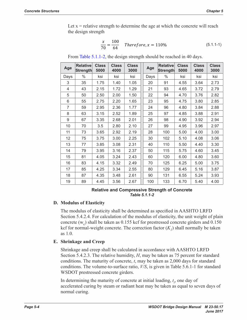
1. Duringdesignorconstructionofabridge,itisnecessarytodeterminethestrength of concrete at various stages of construction. For instance, Standard Specifications Section 6-02.3(17)J discusses the time at which falsework and formscanberemovedtovariouspercentagesoftheconcretedesignstrength.Occasionally,constructionproblemswillarisewhichrequireaknowledgeof the relative strengths of concrete at various ages. Table5.1.1-2shows the approximatevaluesoftheminimumcompressivestrengthsofdifferentclassesofconcreteatvariousages.Iftheconcretehasbeencuredundercontinuousmoistcuringatanaveragetemperature,itcanbeassumedthatthesevalueshavebeendeveloped.
2. Curingoftheconcrete(especiallyinthefirst24hours)has a very important influenceonthestrengthdevelopmentofconcreteatallages.Temperatureaffectstherateatwhichthechemicalreactionbetweencementandwatertakesplace. Loss of moisture can seriously impair the concrete strength.
3. IfteststrengthisaboveorbelowthatshowninTable5.1.1-2, the age at which thedesignstrengthwillbereachedcanbedeterminedbydirectproportion.
For example, if the relative strength at 10 days is 64 percent instead of the minimum 70 percent shown in Table5.1.1-2, the time it takes to reach the designstrengthcanbedeterminedusingequation 5.1.1-1below.
Concrete Structures Chapter 5
Page 5-4 WSDOT Bridge Design Manual M 23-50.17 June 2017
Let x = relative strength to determine the age at which the concrete will reach the design strength
�70 �
10064 ��������������� � � 110� (5 .1 .1-1)
From Table5.1.1-2,thedesignstrengthshouldbereachedin40days.
Age Relative Strength
Class 5000
Class 4000
Class 3000 Age Relative
StrengthClass 5000
Class 4000
Class 3000
Days % ksi ksi ksi Days % ksi ksi ksi3 35 1 .75 1 .40 1 .05 20 91 4 .55 3 .64 2 .734 43 2 .15 1 .72 1 .29 21 93 4 .65 3 .72 2 .795 50 2 .50 2 .00 1 .50 22 94 4 .70 3 .76 2 .826 55 2 .75 2 .20 1 .65 23 95 4 .75 3 .80 2 .857 59 2 .95 2 .36 1 .77 24 96 4 .80 3 .84 2 .888 63 3 .15 2 .52 1 .89 25 97 4 .85 3 .88 2 .919 67 3 .35 2 .68 2 .01 26 98 4 .90 3 .92 2 .94
10 70 3 .5 2 .80 2 .10 27 99 4 .95 3 .96 2 .9711 73 3 .65 2 .92 2 .19 28 100 5 .00 4 .00 3 .0012 75 3 .75 3 .00 2 .25 30 102 5 .10 4 .08 3 .0613 77 3 .85 3 .08 2 .31 40 110 5 .50 4 .40 3 .3014 79 3 .95 3 .16 2 .37 50 115 5 .75 4 .60 3 .4515 81 4 .05 3 .24 2 .43 60 120 6 .00 4 .80 3 .6016 83 4 .15 3 .32 2 .49 70 125 6 .25 5 .00 3 .7517 85 4 .25 3 .34 2 .55 80 129 6 .45 5 .16 3 .8718 87 4 .35 3 .48 2 .61 90 131 6 .55 5 .24 3 .9319 89 4 .45 3 .56 2 .67 100 133 6 .70 5 .40 4 .00
Relative and Compressive Strength of ConcreteTable 5.1.1-2
D. Modulus of Elasticity
The modulus of elasticity shallbedeterminedasspecifiedinAASHTO LRFD Section 5.4.2.4. For calculation of the modulus of elasticity, the unit weight of plain concrete (wc)shallbetakenas0.155kcfforprestressed concrete girders and 0.150 kcf for normal-weight concrete. The correction factor (K1)shallnormallybetakenas 1.0.
E. Shrinkage and Creep
Shrinkage and creepshallbecalculatedin accordance with AASHTO LRFD Section 5.4.2.3. The relative humidity, H,maybetakenas75percentforstandardconditions. The maturity of concrete, t,maybetakenas2,000daysforstandardconditions. The volume-to-surface ratio, V/S,isgiveninTable5.6.1-1forstandardWSDOT prestressed concrete girders.
In determining the maturity of concrete at initial loading, ti, one day of acceleratedcuringbysteamorradiantheatmaybetakenasequaltosevendaysofnormal curing.

Chapter 5 Concrete Structures
WSDOT Bridge Design Manual M 23-50.17 Page 5-5 June 2017
Thefinaldeflectionisacombinationoftheelasticdeflectionandthecreepeffectassociatedwithgivenloadsshownbytheequationbelow.5.1.1‐1 ��� �
����� ���������� � � 11��
5.1.1‐2 ∆������ ∆��������1 � ���� ����
5.1.3‐1 ��� � 12����� · � � ������ · ��.���������
5.1.3‐2 ����� � ������ � ����
�������������� �
5 .1 .3-3 ������� � ������������ For girders within the effective width
5 .1 .3-4 ������� � ����������� For girders outside the effective width
5.1.3‐5 If ������� � ������� then ���� � �������
5.1.3‐6 If ������� � ������� then ���� � ����������������
5.1.3‐7 ���� � �� � ��
5.1.4‐1: � � � ∆����������� �������� ������
5.1.4‐2: ∆��� ������ �������� �������
����
5.1.4‐3: ∆��� � ���1 � ��������� where: � � ������ � �����
�V � 2�L
�H � SR
5.1.4‐4: ∆fpT � ∆fpRO � ∆fpES � ∆fpED � ∆fpLT
5.1.4‐5: ∆���� � ����������
������ � �.55���
5.1.4‐6: ∆���� � ���� ��
������������������������ � ������������������
�� �
5.1.4‐7: ∆���� � ∆���� � ∆���� � ∆���
5.1.4‐7 where: 3 �������� ����� � 3����� � �.�
(5 .1 .1-2)
Figure 5.1.1-1providescreepcoefficientsforarangeoftypicalinitialconcretestrengthvalues,ƒ′ci, as a function of time from initial seven day steam cure (ti=7days).Thefigureusesa volume-to-surface, V/S, ratio of 3.3 as an average for girders and relative humidity, H, equal to 75 percent.
WASHINGTON STATE DEPARTMENT OF TRANSPORTATIONBridge & Structures Branch
500 1 103
× 1.5 103
× 2 103
×
0.25
0.5
0.75
1
1.25
(H=75%, V/S=3.3, ti = 7 days)
(days)
ψ t 7day, 5ksi, ( )
ψ t 7day, 6ksi, ( )
ψ t 7day, 7ksi, ( )
ψ t 7day, 8ksi, ( )
ψ t 7day, 9ksi, ( )
ψ t 7day, 10ksi, ( )
ψ t 7day, 11ksi, ( )
ψ t 7day, 12ksi, ( )
t
CreepCoefficientPlot.xmcd7/16/2010 2:50 PM
p. 1 / 1 JLBeaver/BSACreep Coefficient for Standard Conditions as Function of Initial Concrete Strength
Figure 5.1.1-1
F. Shrinkage
Concrete shrinkage strain, εsh,shallbecalculatedin accordance with AASHTO LRFD.
G. Grout
Groutisusuallyaprepackagedcementbasedgroutornon-shrinkgroutthatismixed,placed,andcuredasrecommendedbythemanufacturer.Itisusedundersteelbaseplatesforbothbridgebearingsandluminariesorsignbridgebases.Shouldthegroutpadthicknessexceed4″,steelreinforcementshallbeused.Fordesignpurposes,thestrengthofthegrout,ifproperlycured,canbeassumedtobeequaltoorgreaterthanthatoftheadjacentconcretebutnotgreaterthan4000psi.Non-shrinkgroutisusedinkeywaysbetweenprecastprestressedtri-beams,double-tees,anddeckbulbtees(see Standard Specifications Section 6-02.3(25)O fordeckbulbteeexception).

Concrete Structures Chapter 5
Page 5-6 WSDOT Bridge Design Manual M 23-50.17 June 2017
H. Mass Concrete
Mass concrete is any volume of concrete with dimensions large enough to require thatmeasuresbetakentocopewiththegenerationofheatfromhydrationofthecement and attendant volume change to minimize cracking. Temperature-related crackingmaybeexperiencedinthick-sectionconcretestructures,includingspreadfootings,pilecaps,bridgepiers,crossbeams,thickwalls,andotherstructuresasapplicable.
Concreteplacementswithleastdimensiongreaterthan6feetshouldbeconsideredmass concrete, although smaller placements with least dimension greater than 3feetmayalsohaveproblemswithheatgenerationeffects.Shaneednotbeconsidered mass concrete.
The temperature of mass concrete shall not exceed 160°F. The temperature differencebetweenthegeometriccenteroftheconcreteandthecenterofnearbyexterior surfaces shall not exceed 35°F.
Designerscouldmitigateheatgenerationeffectsbyspecifyingconstructionjointsand placement intervals. Designers should consider requiring the Contractor tosubmitathermalcontrolplan,whichmayincludesuchthingsas:1. Temperature monitors and equipment.2. Insulation.3. Concretecoolingbeforeplacement.4. Concretecoolingafterplacement,suchasbymeansofinternalcoolingpipes.5. Use of smaller, less frequent placements.6. OthermethodsproposedbytheContractorandapprovedbytheEngineer
of Record.
Concretemixdesignoptimization,suchasusinglow-heatcement,flyashorslagcement, low-water/cement ratio, low cementitious materials content, larger aggregate,etc.isacceptableaslongastheconcretemixmeetstherequirementsof the Standard Specifications forthespecifiedconcreteclass.
TheACIManualofConcretePracticePublication207andspecificationsusedfortheTacomaNarrowsBridgeProjectsuspensioncableanchorages(2003-2006)canbeusedasreferences.
I. Self-Consolidating Concrete (SCC)
Self-consolidatingconcrete(SCC)maybeusedinstructuralmemberssuchasprecastnoisewallpanels,barriers,three-sidedstructures,etc.asdescribedinStandard Specifications Section 6-02.3(27).
SCCmaybeusedinprestressedconcretegirders.
SCCmaybespecifiedforcast-in-placeapplicationswheretheuseofconventionalconcretecouldbechallengingandproblematic.Examplesarewherenewconcreteisbeingcastupagainstanexistingsoffit,orinmemberswithverydense/congested reinforcing steel. Use of SCC for primary structural components such ascolumns,crossbeams,slabs,etc.requirestheapprovaloftheWSDOTBridgeDesign Engineer.

Chapter 5 Concrete Structures
WSDOT Bridge Design Manual M 23-50.17 Page 5-7 June 2017
J. Shotcrete
ShotcretecouldbeusedasspecifiedinWSDOTStandardPlans.ShotcretemaynotbesuitableforsomecriticalapplicationsunlessapprovedbytheEngineerofRecord.
SubstitutionofCIPconventionalconcreteinthecontractdocumentwithshotcreterequires the approval of the Engineer of Record.
Some potential shortfalls of shotcrete as compared to conventional CIP concrete include:• Durability–Conventionalconcreteisplacedinformsandvibratedforconsolidation.Shotcrete,whetherplacedbywetordrymaterialfeed,ispneumatically applied to the surface and is not consolidated as conventional concrete.Duetothedifferenceinconsolidation,permeabilitycanbeaffected.Ifthepermeabilityisnotlowenough,theservicelifeoftheshotcretewillbeaffectedandmaynotmeettheminimumof75yearsspecifiedforconventional concretes.
Observationofsomeprojectsindicatestheinadequateperformanceofshotcretetoproperlyholdbackwater.Thisresultsinleakingandpotentialfreezing,seemingly at a higher rate than conventional concrete. Due to the method of placementofshotcrete,airentrainmentisdifficulttocontrol.Thisleadstolessresistance of freeze/thaw cycles.
• Cracking –Thereismorecrackingobservedinshotcretesurfacescomparedtoconventionalconcrete.Excessivecrackinginshotcretecouldbeattributedto its higher shrinkage, method of curing, and lesser resistance to freeze/thaw cycles.Theshotcretecrackingismoreevidentwhenstructureissubjectedtodifferentialshrinkage.
• Corrosion Protection –Thehigherpermeabilityofshotcreteplacesthesteelreinforcement(whethermeshorbars)atahigherriskofcorrosionthanconventional concrete applications. Consideration for corrosion protection may benecessaryforsomecriticalshotcreteapplications.
• Safety – Carved shotcrete and shotcrete that needs a high degree of relief to accentarchitecturalfeaturesleadtoareasof4″-6″ofunreinforcedshotcrete.Theseareascanbepronetoanacceleratedrateofdeterioration.This,inturn,placespedestrians,bicyclists,andtrafficnexttothewallatriskoffallingdebris.
• Visual Quality and Corridor Continuity–Asshotcreteisfinishedbyhand,standardarchitecturaldesign,asdefinedintheDesign Manual M 22-01, typicallycannotbemet.Thiscancreateconflictswiththearchitecturalguidelines developed for the corridor. Many times the guidelines are developed withpublicinput.Iftheguidelinesarenotmet,thepublicdevelopsadistrustoftheprocess.Inothercases,theuseoffauxrockfinishes,morecommonlyusedbytheprivatesector,cancreatetheperceptionofthemisuseofpublicfunds.
K. Lightweight Aggregate Concrete
LightweightaggregateconcretemaybeusedforprecastandCIPmembersuponapproval of the WSDOT Bridge Design Engineer.

Concrete Structures Chapter 5
Page 5-8 WSDOT Bridge Design Manual M 23-50.17 June 2017
L. Concrete Cover to Reinforcement
Concrete cover to reinforcement shall conform to AASHTO LRFD Section 5.10.1.
1. Precast Prestressed Concrete Girders
Covertoprestressingstrandsinprecastprestressedconcretegirdersmaybemeasured to the center of the strand.
Cover to mild steel reinforcement in precast prestressed concrete girders shall conform to AASHTO LRFD Section 5.10.1. However, cover to ties and stirrups maybereducedto1.0inchin“Exteriorotherthanabove”applications.SeeSection 5.6.7.A for additional cover requirements for deck girders.
5.1.2 Reinforcing SteelA. Grades
ReinforcingbarsshallbedeformedandshallconformtoStandard Specifications Section 9-07.2. AASHTO M 31 Grade 60 or ASTM A 706 Grade 60 reinforcement maybeusedinprestressedconcretegirders.ASTMA706Grade60reinforcementispreferredforallotherbridgeandstructurecomponents.
1. Grade 80 Reinforcement
Reinforcement conforming to ASTM A706 Grade 80maybeusedinSeismicDesign Category (SDC) A for all components. For SDCs B, C and D, ASTM A706 Grade 80reinforcingsteelshallnotbeusedforelementsandconnectionsthatareproportionedanddetailedtoensurethedevelopmentofsignificantinelastic deformations for which moment curvature analysis is required to determinetheplasticmomentcapacityofductileconcretemembersandexpectednominalmomentcapacityofcapacityprotectedmembers.
ASTM A706 Grade 80reinforcingsteelmaybeusedforcapacity-protectedmemberssuchasfootings,bentcaps,oversizedshafts,joints,andintegralsuperstructure elements that are adjacent to the plastic hinge locations if the expectednominalmomentcapacityisdeterminedbystrengthdesignbasedontheexpectedconcretecompressivestrengthwithamaximumusablestrainof0.003andareinforcingsteelyieldstrengthof80ksiwithamaximumusablestrainof0.090for#10barsandsmaller,0.060for#11barsandlarger.Theresistancefactorsforseismicrelatedcalculationsshallbetakenas0.90forshearand1.0forbending.
ASTM A706 Grade 80reinforcingsteelshallnotbeusedforoversizedshaftswhere in-ground plastic hinging is considered as a part of the Earthquake-Resisting System (ERS).
ASTM A706 Grade 80reinforcingsteelshallnotbeusedfortransverseandconfinementreinforcement.
For seismic hooks, fyshallnotbetakengreaterthan75ksi.

Chapter 5 Concrete Structures
WSDOT Bridge Design Manual M 23-50.17 Page 5-9 June 2017
B. Sizes
Reinforcingbarsarereferredtointhecontractplansandspecificationsbynumberandvaryinsizefrom#3to#18.Forbarsuptoandincluding#8,thenumberofthebarcoincideswiththebardiameterineighthsofaninch.The#9,#10,and#11barshavediametersthatprovideareasequalto1″×1″squarebars,1⅛″×1⅛″squarebarsand1¼″×1¼″squarebarsrespectively.Similarly,the#14and#18barscorrespondto1½″×1½″and2″×2″squarebars,respectively.Appendix 5.1-A3showsthesizes,number,andvariouspropertiesofthetypesofbarsusedinWashington State.
C. Development
1. Tension Development Length
Developmentlengthoranchorageofreinforcementisrequiredonbothsides of a point of maximum stress at any section of a reinforced concrete member.Developmentofreinforcementintensionshallbein accordance with AASHTO LRFD Section 5.10.8.2.1.
Appendix 5.1-A4 showsthetensiondevelopmentlengthforbothuncoatedandepoxycoatedGrade60barsfornormalweightconcretewithspecifiedstrengthsof 4.0 to 6.0 ksi.
2. Compression Development Length
Developmentofreinforcementincompressionshallbein accordance with AASHTO LRFD Section 5.10.8.2.2. ThebasicdevelopmentlengthsfordeformedbarsincompressionareshowninAppendix 5.1-A5. These valuesmaybemodifiedasdescribedinAASHTO. However, the minimum development length shallbe1′-0″.
3. Tension Development Length of Standard Hooks
Standardhooksareusedtodevelopbarsintensionwherespacelimitationsrestricttheuseofstraightbars.DevelopmentofstandardhooksintensionshallbeinaccordancewithAASHTOLRFD Section 5.10.8.2.4. Tension development lengths of 90° & 180° standard hooks are shown in Appendix 5.1-A6.
D. Splices
The Contract Plans shall clearly show the locations and lengths of splices. Splices shallbein accordance with AASHTO LRFD Section 5.10.8.4.
Lapsplices,foreithertensionorcompressionbars,shallnotbelessthan2′-0″.
1. Tension Lap Splices
Manyofthesamefactorswhichaffectdevelopmentlengthaffectsplices.Consequently,tensionlapsplicesareafunctionofthebar’sdevelopmentlength, l
d.Therearetwoclassesoftensionlapsplices:ClassAandB.Designers
areencouragedtosplicebarsatpointsofminimumstressandtostaggerlapsplicesalongthelengthofthebars.
Appendix 5.1-A7showstensionlapsplicesforbothuncoatedandepoxycoatedGrade60barsfornormalweightconcretewithspecifiedstrengthsof4.0to6.0 ksi.

Concrete Structures Chapter 5
Page 5-10 WSDOT Bridge Design Manual M 23-50.17 June 2017
2. Compression Lap Splices
Compression lap splice lengths are shown in Appendix 5.1-A5 for concrete strengths greater than or equal to 3.0 ksi.
3. Mechanical Splices
Mechanical splices are proprietary splicing mechanisms. The requirements for mechanical splices are found in Standard Specifications Section 6-02.3(24)F and in AASHTO LRFD Sections 5.5.3.4 and 5.10.8.4.2b.
4. Welded Splices
AASHTO LRFD Section 5.10.8.4.2cdescribestherequirementsforwelded splices.Onmodificationstoexistingstructures,weldingofreinforcingbarsmaynotbepossiblebecauseofthenon-weldabilityofsomesteels.
E. Hooks and Bends
Forhookandbendrequirements,seeAASHTO LRFD Section 5.10.2. Standard hooksandbendradiiareshowninAppendix 5.1-A1.
F. Fabrication Lengths
Reinforcingbarsareavailableinstandardmilllengthsof40′forbarsizes#3and #4 and 60′forbarsizesof#5andgreater.Designersshalllimitreinforcingbarlengthstothestandardmilllengths. Because of placement considerations, designers should consider limiting the overall lengthsofbarsize#3to30′andbarsize#5to40′.
Spiralsofbarsizes#4through#6areavailableon5,000lbcoils.Spiralsshouldbelimitedtoamaximumbarsizeof#6.
G. Placement
Placementofreinforcingbarscanbeaproblemduringconstruction.Sometimesitmaybenecessarytomakealargescaledrawingofreinforcementtolookforinterferenceandplacementproblemsinconfinedareas. If interference is expected, additional details are required in the contract plans showing how to handle the interferenceandplacementproblems.Appendix 5.1-A2 shows the minimum clearanceandspacingofreinforcementforbeamsandcolumns.
H. Joint and Corner Details
1. T-Joint
The forces form a tension crack at 45° in the joint. Reinforcement as shown in Figure 5.1.2-1ismorethantwiceaseffectiveindevelopingthestrengthofthecorner than if the reinforcement was turned 180°.
2. “Normal” Right Corners
CornerssubjectedtobendingasshowninFigure 5.1.2-2 will crack radially in the corner outside of the main reinforcing steel. Smaller size reinforcing steel shallbeprovidedinthecornertodistributetheradialcracking.

Chapter 5 Concrete Structures
WSDOT Bridge Design Manual M 23-50.17 Page 5-11 June 2017
3. Right or Obtuse Angle Corners
CornerssubjectedtobendingasshowninFigure 5.1.2-3 tend to crack at the reentrant corner and fail in tension across the corner. If not properly reinforced, theresistingcornermomentmaybelessthantheappliedmoment.
Reinforced as shown in Figure 5.1.2-3,butwithoutthediagonalreinforcingsteel across the corner, the section will develop 85 percent of the ultimate momentcapacityofthewall.Ifthebendswererotated180°,only30percentofthewallcapacitywouldbedeveloped.
Adding diagonal reinforcing steel across the corner, approximately equal to 50 percent of the main reinforcing steel, will develop the corner strength to fully resist the applied moment. Extend the diagonal reinforcement past the cornereachdirectionforanchorage.Sincethisbararrangementwillfullydeveloptheresistingmoment,afilletinthecornerisnormallyunnecessary.
Concrete Structures Chapter 5
Page 5.1-8 WSDOT Bridge Design Manual M 23-50.06 July 2011
• 1.33 times the factored moment required by the applicable strength load combinations specified in LRFD Table 3.4.1-1.
2. Compression – For compression members, the area of longitudinal reinforcement shall meet the requirements of AASHTO LRFD 5.7.4.2 and AASHTO Guide Specifications for LRFD Seismic Bridge Design 8.8. Additional lateral reinforcement requirements are given in AASHTO LRFD 5.7.4 and the AASHTO Guide Specifications for LRFD Seismic Bridge Design.
I. Joint and Corner Details –
1. T-Joint – The forces form a tension crack at 45° in the joint. Reinforcement as shown in Figure 5.1.2-1 is more than twice as effective in developing the strength of the corner than if the reinforcement was turned 180°.
2. “Normal” Right Corners – Corners subjected to bending as shown in Figure 5.1.2-2 will crack radially in the corner outside of the main reinforcing steel. Smaller size reinforcing steel shall be provided in the corner to distribute the radial cracking.
3. Right or Obtuse Angle Corners – Corners subjected to bending as shown in Figure 5.1.2-3 tend to crack at the reentrant corner and fail in tension across the corner. If not properly reinforced, the resisting corner moment may be less than the applied moment.
Reinforced as shown in Figure 5.1.2-3, but without the diagonal reinforcing steel across the corner, the section will develop 85% of the ultimate moment capacity of the wall. If the bends were rotated 180°, only 30% of the wall capacity would be developed.
Adding diagonal reinforcing steel across the corner, approximately equal to 50% of the main reinforcing steel, will develop the corner strength to fully resist the applied moment. Extend the diagonal reinforcement past the corner each direction for anchorage. Since this bar arrangement will fully develop the resisting moment, a fillet in the corner is normally unnecessary.
T-Joint Reinforcing DetailsFigure 5.1.2-1
“Normal” Right Corner Reinforcing Details
Figure 5.1.2-2
Right or Obtuse Angle Corner Reinforcing Details
Figure 5.1.2-3
J. Welded Wire Reinforcement in Precast Prestressed Girders – Welded wire reinforcement can be used to replace mild steel reinforcement in precast prestressed girders. Welded wire reinforcement shall meet all AASHTO requirements (see AASHTO LRFD 5.4.3, 5.8.2.6, 5.8.2.8, C.5.8.2.8, 5.10.6.3, 5.10.7, 5.10.8, 5.11.2.6.3, etc.).
The yield strength shall be greater than or equal to 60 ksi. The design yield strength shall be 60 ksi. Welded wire reinforcement shall be deformed. Welded wire reinforcement shall have the same area and spacing as the mild steel reinforcement that it replaces.
T-Joint Reinforcing DetailsFigure 5.1.2-1
“Normal” Right Corner Reinforcing Details
Figure 5.1.2-2
Right or Obtuse Angle Corner Reinforcing Details
Figure 5.1.2-3
I. Welded Wire Reinforcement in Prestressed Concrete Girders, Walls, Barriers and Deck Panels
Weldedwirereinforcementmaybeusedtoreplacesteelreinforcingbarsinprestressedconcretegirders,walls,barriers,anddeckpanels.
Welded wire reinforcement shall meet all AASHTO requirements.
Weldedwirereinforcementshallbedeformed.Theyieldstrengthshallbelimitedto a maximum of 75 ksi.
Longitudinalwiresandweldsshallbeexcludedfromregionswithhighsheardemands,includinggirderwebs,andarelimitedtotheflangeareasasdescribedinAASHTO LRFD Section 5.8.2.8. Longitudinal wires for anchorage of welded wire reinforcementshallhaveanareaof40percentormoreoftheareaofthewirebeinganchoredasdescribedinASTM A497butshallnotbelessthanD4.
Epoxy-coated wire and welded wire reinforcement shall conform to Standard Specifications Section 9-07.3 with the exception that ASTM A884 Class A Type I shallbeusedinsteadofASTM A775.

Concrete Structures Chapter 5
Page 5-12 WSDOT Bridge Design Manual M 23-50.17 June 2017
J. Headed Steel Reinforcing Bars
HeadedsteelreinforcingbarsconformingtoASTM A970ClassHAmaybeusedtodevelopreinforcementintension.Useanddevelopmentlengthshallbeinaccordance with ACI 318 (see Section 25.4.4 for development length). Minimum concretecoverandclearancestoheadedsteelreinforcingbarsshallalsobeprovidedtotheoutermostpartoftheheadofthebar.Designersshallprovidemainbar(unheadedportion)locationrequirementsincontractdocumentsandverifythatcoverandclearancerequirementstotheheadofthebarcanbesatisfied.ASTM A970ClassHArequiresthatthenetbearingareaoftheheadshallnotbelessthanfourtimesthenominalcross-sectionalareaofthebar.However,theheadshapeandanupperlimittotheheadnetbearingareaarenotspecified.Agrossheadareaoftentimesthebararea(anetbearingareaoftheheadofninetimesthebararea)couldbeusedasanestimateoftheupperlimitoftheheadarea.
5.1.3 Prestressing SteelA. General
Threetypesofhigh-tensilesteelusedforprestressingsteelare:
1. Strands
AASHTO M 203 Grade 270, low relaxation or stress relieved
2. Bars
AASHTO M 275 Type II
3. Parallel Wires
AASHTO M 204 Type WA
AllWSDOTdesignsarebasedonlowrelaxationstrandsusingeither0.5″or0.6″diameter strands for girders, and ⅜″or7/16″diameter strands for stay-in-place precast deck panels. Properties of uncoated and epoxy-coated prestressing stands are shown in Appendix 5.1-A8.0.62″and0.7″diameterstrandsmaybeusedfortop temporary strands in prestressed concrete girders.
Provide adequate concrete cover and consider use of epoxy coated prestressing reinforcementincoastalareasorwheremembersaredirectlyexposedtosaltwater.
B. Allowable Stresses
AllowablestressesforprestressingsteelareaslistedinAASHTOLRFD Section 5.9.2.2.
C. Prestressing Strands
Standard strand patterns for all types of WSDOT prestressed concrete girders are shown ontheBridgeStandardDrawingswebsite(www.wsdot.wa.gov/Bridge/Structures/StandardDrawings.htm).
1. Straight Strands
Thepositionofthestraightstrandsinthebottomflangeis standardized for each girder type.
Chapter 5 Concrete Structures
WSDOT Bridge Design Manual M 23-50.17 Page 5-13 June 2017
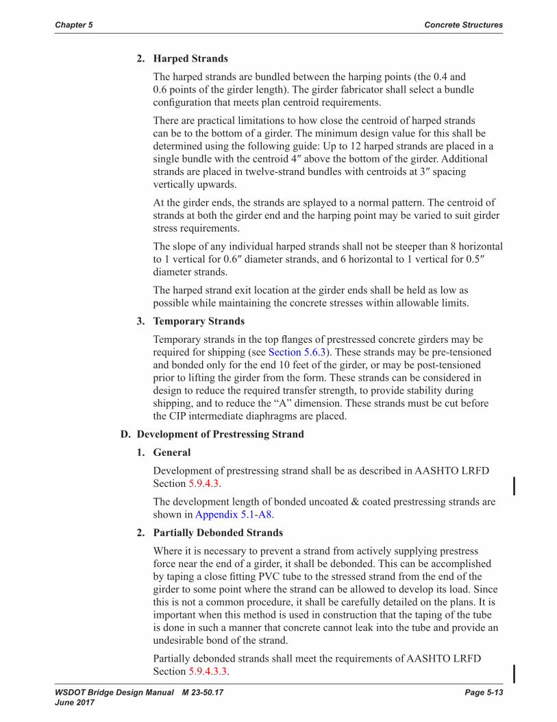
2. Harped Strands
Theharpedstrandsarebundledbetweentheharpingpoints(the 0.4 and 0.6 points of the girder length).Thegirderfabricatorshallselectabundleconfigurationthatmeetsplancentroidrequirements.
There are practical limitations to how close the centroid of harped strands canbetothebottomofagirder.Theminimumdesignvalueforthisshallbedeterminedusingthefollowingguide:Upto12harped strands are placed in a singlebundlewiththecentroid4″abovethebottomofthegirder.Additional strandsareplacedintwelve-strandbundleswithcentroidsat3″ spacing vertically upwards.
At the girder ends, the strands are splayed to a normal pattern. The centroid of strandsatboththegirderendandtheharpingpointmaybevariedtosuitgirderstress requirements.
The slope of any individualharpedstrandsshallnotbesteeperthan8horizontalto 1 vertical for 0.6″ diameter strands, and 6 horizontal to 1 vertical for 0.5″ diameter strands.
Theharpedstrandexitlocationatthegirderendsshallbeheldaslowaspossiblewhilemaintainingtheconcretestresseswithinallowablelimits.
3. Temporary Strands
Temporarystrandsinthetopflangesofprestressed concretegirdersmayberequired for shipping (see Section 5.6.3).Thesestrandsmaybepre-tensionedandbondedonlyfortheend10feetofthegirder,ormaybepost-tensionedpriortoliftingthegirderfromtheform.Thesestrandscanbeconsideredindesigntoreducetherequiredtransferstrength,toprovidestabilityduringshipping,andtoreducethe“A”dimension.Thesestrandsmustbecutbeforethe CIP intermediate diaphragms are placed.
D. Development of Prestressing Strand
1. General
DevelopmentofprestressingstrandshallbeasdescribedinAASHTOLRFDSection 5.9.4.3.
The development length of bonded uncoated & coated prestressing strands are shown in Appendix 5.1-A8.
2. Partially Debonded Strands
Where it is necessary to prevent a strand from actively supplying prestress force near the end of a girder, it shallbedebonded.ThiscanbeaccomplishedbytapingaclosefittingPVCtubetothestressedstrandfromtheendofthegirdertosomepointwherethestrandcanbeallowedtodevelopitsload.Sincethis is not a common procedure, it shallbecarefullydetailedontheplans.Itisimportantwhenthismethodisusedinconstructionthatthetapingofthetubeisdoneinsuchamannerthatconcretecannotleakintothetubeandprovideanundesirablebondofthestrand.
PartiallydebondedstrandsshallmeettherequirementsofAASHTOLRFDSection 5.9.4.3.3.
Concrete Structures Chapter 5
Page 5-14 WSDOT Bridge Design Manual M 23-50.17 June 2017
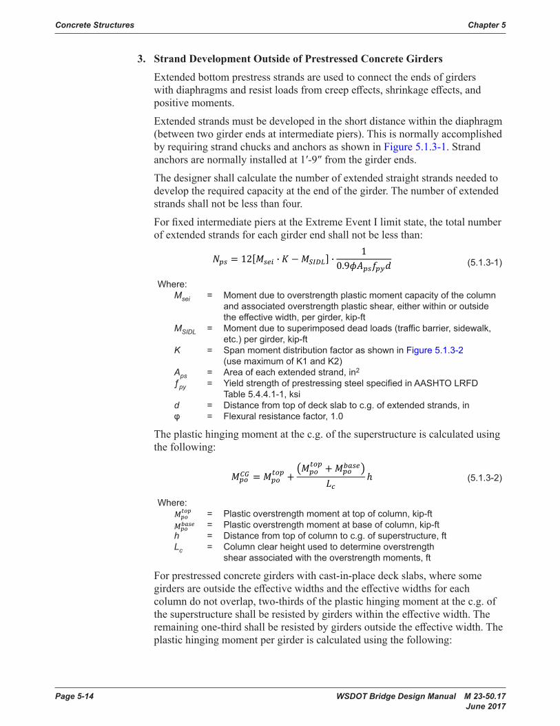
3. Strand Development Outside of Prestressed Concrete Girders
Extendedbottomprestressstrandsareusedtoconnecttheendsofgirderswithdiaphragmsandresistloadsfromcreepeffects,shrinkageeffects, and positive moments.
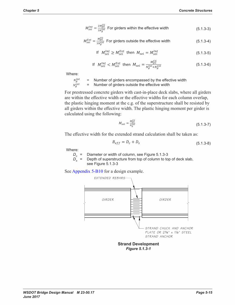
Extended strandsmustbedevelopedintheshortdistancewithinthediaphragm(betweentwogirderendsatintermediatepiers).ThisisnormallyaccomplishedbyrequiringstrandchucksandanchorsasshowninFigure 5.1.3-1. Strand anchors are normally installed at1′-9″from the girder ends.
Thedesignershallcalculatethenumberofextendedstraightstrandsneededtodeveloptherequiredcapacityattheendofthegirder.Thenumberofextendedstrandsshallnotbelessthanfour.
ForfixedintermediatepiersattheExtremeEventIlimitstate,thetotalnumberof extended strands for each girder endshallnotbelessthan:
��� � 1������ · � � ������ · 1����������� (5 .1 .3-1)
Where: Msei = Moment due to overstrength plastic moment capacity of the column and associated overstrength plastic shear, either within or outside the effective width, per girder, kip-ft MSIDL = Moment due to superimposed dead loads (traffic barrier, sidewalk, etc .) per girder, kip-ft K = Span moment distribution factor as shown in Figure 5 .1 .3-2 (use maximum of K1 and K2) Aps = Area of each extended strand, in2
ƒpy = Yield strength of prestressing steel specified in AASHTO LRFD Table 5.4.4.1-1, ksi d = Distance from top of deck slab to c.g. of extended strands, in φ = Flexural resistance factor, 1.0
The plastic hinging moment at the c.g. of the superstructure is calculated using thefollowing:
(5 .1 .3-2)
Where:
5.1.1‐1 ��� ������ ���������� � � 11��
5.1.1‐2 ∆������ ∆��������1 � ���� ����
5.1.3‐1 ��� � 12����� · � � ������ · ��.���������
5.1.3‐2 ����� � ������ � ����
�������������� �
5.1.3‐2 WhereA ������
5.1.3‐2 WhereB �������
5 .1 .3-3 ������� � ������������ For girders within the effective width
5 .1 .3-4 ������� � ����������� For girders outside the effective width
5.1.3‐5 If ������� � ������� then ���� � �������
5.1.3‐6 If ������� � ������� then ���� � ����������������
5.1.3‐7 ���� � �� � ��
5.1.4‐1: � � � ∆����������� �������� ������
5.1.4‐2: ∆��� ������ �������� �������
����
5.1.4‐3: ∆��� � ����1 � ���������� 5.1.4‐4: ∆fpT � ∆fpRO � ∆fpES � ∆fpED � ∆fpLT
5.1.4‐5: ∆���� � ���������� ������� � �.55� ���
5.1.4‐6: ∆���� � ���� ��
������������������������ � ������������������
�� �
5.1.4‐7: ∆���� � ∆���� � ∆���� � ∆���
5.1.4‐7 where: 3 �������� ����� � 3����� � �.�
= Plastic overstrength moment at top of column, kip-ft
5.1.1‐1 ��� ������ ���������� � � 11��
5.1.1‐2 ∆������ ∆��������1 � ���� ����
5.1.3‐1 ��� � 12����� · � � ������ · ��.���������
5.1.3‐2 ����� � ������ � ����
�������������� �
5.1.3‐2 WhereA ������
5.1.3‐2 WhereB �������
5 .1 .3-3 ������� � ������������ For girders within the effective width
5 .1 .3-4 ������� � ����������� For girders outside the effective width
5.1.3‐5 If ������� � ������� then ���� � �������
5.1.3‐6 If ������� � ������� then ���� � ����������������
5.1.3‐7 ���� � �� � ��
5.1.4‐1: � � � ∆����������� �������� ������
5.1.4‐2: ∆��� ������ �������� �������
����
5.1.4‐3: ∆��� � ����1 � ���������� 5.1.4‐4: ∆fpT � ∆fpRO � ∆fpES � ∆fpED � ∆fpLT
5.1.4‐5: ∆���� � ���������� ������� � �.55� ���
5.1.4‐6: ∆���� � ���� ��
������������������������ � ������������������
�� �
5.1.4‐7: ∆���� � ∆���� � ∆���� � ∆���
5.1.4‐7 where: 3 �������� ����� � 3����� � �.�
= Plastic overstrength moment at base of column, kip-ft h = Distance from top of column to c .g . of superstructure, ft Lc = Column clear height used to determine overstrength shear associated with the overstrength moments, ft
Forprestressedconcretegirderswithcast-in-placedeckslabs,wheresomegirdersareoutsidetheeffectivewidthsandtheeffectivewidthsforeachcolumn do not overlap, two-thirds of the plastic hinging moment at the c.g. of thesuperstructureshallberesistedbygirderswithintheeffectivewidth.Theremainingone-thirdshallberesistedbygirdersoutsidetheeffectivewidth.Theplastichingingmomentpergirderiscalculatedusingthefollowing:
Chapter 5 Concrete Structures
WSDOT Bridge Design Manual M 23-50.17 Page 5-15 June 2017
5.1.1‐1 x70� 100
64 Therefore, x � 110%
5.1.1‐2 ∆total� ∆elastic�1� ��t, ti��
5.1.3‐1 ��� � 12����� · � � ������ · ��.���������
5.1.3‐2 ����� � ������ � ����
�������������� �
5 .1 .3-3 ������� � ������������ For girders within the effective width
5 .1 .3-4 ������� � ����������� For girders outside the effective width
5.1.3‐5 If ������� � ������� then ���� � �������
5.1.3‐6 If ������� � ������� then ���� � ����������������
5.1.4‐1: � � � ∆����������� �������� ������
5.1.4‐2: ∆��� ������ �������� �������
����
5.1.4‐3: ∆��� � ���1 � ��������� 5.1.4‐3 where: � � ������ � �����
�V � 2�L
�H � SR
5.1.4‐4: ∆fpT � ∆fpRO � ∆fpES � ∆fpED � ∆fpLT
5.1.4‐5: ∆���� � ����������
������ � �.55���
5.1.4‐6: ∆���� � ���� ��
������������������������ � ������������������
�� �
5.1.4‐7: ∆���� � ∆���� � ∆���� � ∆���
(5 .1 .3-3)
5.1.1‐1 x70� 100
64 Therefore, x � 110%
5.1.1‐2 ∆total� ∆elastic�1� ��t, ti��
5.1.3‐1 ��� � 12����� · � � ������ · ��.���������
5.1.3‐2 ����� � ������ � ����
�������������� �
5 .1 .3-3 ������� � ������������ For girders within the effective width
5 .1 .3-4 ������� � ����������� For girders outside the effective width
5.1.3‐5 If ������� � ������� then ���� � �������
5.1.3‐6 If ������� � ������� then ���� � ����������������
5.1.4‐1: � � � ∆����������� �������� ������
5.1.4‐2: ∆��� ������ �������� �������
����
5.1.4‐3: ∆��� � ���1 � ��������� 5.1.4‐3 where: � � ������ � �����
�V � 2�L
�H � SR
5.1.4‐4: ∆fpT � ∆fpRO � ∆fpES � ∆fpED � ∆fpLT
5.1.4‐5: ∆���� � ����������
������ � �.55���
5.1.4‐6: ∆���� � ���� ��
������������������������ � ������������������
�� �
5.1.4‐7: ∆���� � ∆���� � ∆���� � ∆���
(5 .1 .3-4)
5.1.1‐1 x70� 100
64 Therefore, x � 110%
5.1.1‐2 ∆total� ∆elastic�1� ��t, ti��
5.1.3‐1 ��� � 12����� · � � ������ · ��.���������
5.1.3‐2 ����� � ������ � ����
�������������� �
5.1.3‐3 ������� � ������������ For girders within the effective width
5.1.3‐4 ������� � ����������� For girders outside the effective width
5.1.3‐5 If ������� � ������� then ���� � �������
5.1.3‐6 If ������� � ������� then ���� � ����������������
5.1.4‐1: � � � ∆����������� �������� ������
5.1.4‐2: ∆��� ������ �������� �������
����
5.1.4‐3: ∆��� � ���1 � ��������� 5.1.4‐3 where: � � ������ � �����
�V � 2�L
�H � SR
5.1.4‐4: ∆fpT � ∆fpRO � ∆fpES � ∆fpED � ∆fpLT
5.1.4‐5: ∆���� � ����������
������ � �.55���
5.1.4‐6: ∆���� � ���� ��
������������������������ � ������������������
�� �
5.1.4‐7: ∆���� � ∆���� � ∆���� � ∆���
(5 .1 .3-5)
5.1.1‐1 x70� 100
64 Therefore, x � 110%
5.1.1‐2 ∆total� ∆elastic�1� ��t, ti��
5.1.3‐1 ��� � 12����� · � � ������ · ��.���������
5.1.3‐2 ����� � ������ � ����
�������������� �
5.1.3‐3 ������� � ������������ For girders within the effective width
5.1.3‐4 ������� � ����������� For girders outside the effective width
5.1.3‐5 If ������� � ������� then ���� � �������
5.1.3‐6 If ������� � ������� then ���� � ����������������
5.1.4‐1: � � � ∆����������� �������� ������
5.1.4‐2: ∆��� ������ �������� �������
����
5.1.4‐3: ∆��� � ���1 � ��������� 5.1.4‐3 where: � � ������ � �����
�V � 2�L
�H � SR
5.1.4‐4: ∆fpT � ∆fpRO � ∆fpES � ∆fpED � ∆fpLT
5.1.4‐5: ∆���� � ����������
������ � �.55���
5.1.4‐6: ∆���� � ���� ��
������������������������ � ������������������
�� �
5.1.4‐7: ∆���� � ∆���� � ∆���� � ∆���
(5 .1 .3-6)
Where:
5.1.1‐1 x70� 100
64 Therefore, x � 110%
5.1.1‐2 ∆total� ∆elastic�1� ��t, ti��
5.1.3‐1 ��� � 12����� · � � ������ · ��.���������
5.1.3‐2 ����� � ������ � ����
�������������� �
5.1.3‐3 ������� � ������������ For girders within the effective width
5.1.3‐4 ������� � ����������� For girders outside the effective width
5.1.3‐5 If ������� � ������� then ���� � �������
5.1.3‐6 If ������� � ������� then ���� � ����������������
5.1.4‐1: � � � ∆����������� �������� ������
5.1.4‐2: ∆��� ������ �������� �������
����
5.1.4‐3: ∆��� � ���1 � ��������� 5.1.4‐3 where: � � ������ � �����
�V � 2�L
�H � SR
5.1.4‐4: ∆fpT � ∆fpRO � ∆fpES � ∆fpED � ∆fpLT
5.1.4‐5: ∆���� � ����������
������ � �.55���
5.1.4‐6: ∆���� � ���� ��
������������������������ � ������������������
�� �
5.1.4‐7: ∆���� � ∆���� � ∆���� � ∆���
= Number of girders encompassed by the effective width
5.1.1‐1 x70� 100
64 Therefore, x � 110%
5.1.1‐2 ∆total� ∆elastic�1� ��t, ti��
5.1.3‐1 ��� � 12����� · � � ������ · ��.���������
5.1.3‐2 ����� � ������ � ����
�������������� �
5.1.3‐3 ������� � ������������ For girders within the effective width
5.1.3‐4 ������� � ����������� For girders outside the effective width
5.1.3‐5 If ������� � ������� then ���� � �������
5.1.3‐6 If ������� � ������� then ���� � ����������������
5.1.4‐1: � � � ∆����������� �������� ������
5.1.4‐2: ∆��� ������ �������� �������
����
5.1.4‐3: ∆��� � ���1 � ��������� 5.1.4‐3 where: � � ������ � �����
�V � 2�L
�H � SR
5.1.4‐4: ∆fpT � ∆fpRO � ∆fpES � ∆fpED � ∆fpLT
5.1.4‐5: ∆���� � ����������
������ � �.55���
5.1.4‐6: ∆���� � ���� ��
������������������������ � ������������������
�� �
5.1.4‐7: ∆���� � ∆���� � ∆���� � ∆���
= Number of girders outside the effective width
Forprestressedconcretegirderswithcast-in-placedeckslabs,whereallgirdersarewithintheeffectivewidthortheeffectivewidthsforeachcolumnoverlap,theplastichingingmomentatthec.g.ofthesuperstructureshallberesistedbyallgirderswithintheeffectivewidth.Theplastichingingmomentpergirderiscalculatedusingthefollowing:
Where:= Plastic overstrength moment at top of column, kip-ft= Plasticoverstrengthmomentatbaseofcolumn,kip-ft
h = Distance from top of column to c.g. of superstructure, ftLc = Column clear height used to determine overstrength shear associated with the
overstrength moments, ft
For precast, prestressed girders with cast-in-placedeckslabs, where some girders are outside the effective widths and the effective widths for each column do not overlap, two-thirds of the plastic hinging moment at the c.g. ofthesuperstructureshallberesistedbygirderswithintheeffectivewidth. The remaining one-thirdshallberesistedbygirdersoutsidetheeffectivewidth.Theplastichingingmomentpergirderiscalculatedusingthefollowing:
For girders within the effective width(5 .1 .3-3)
For girders outside the effective width(5 .1 .3-4)
If then (5 .1 .3-5)
If then (5 .1 .3-6)
Where:= Numberofgirdersencompassedbythe effective width= Numberofgirdersoutsidetheeffectivewidth
For precast, prestressed girders with cast-in-placedeckslabs, where all girders are within the effective width or the effective widths for each column overlap, the plastic hinging moment at the c.g.ofthesuperstructureshallberesistedbyall girders within the effective width. The plastic hingingmomentpergirderiscalculatedusingthefollowing:
𝑀𝑀𝑠𝑠𝑠𝑠𝑠𝑠 = 𝑀𝑀𝑝𝑝𝑝𝑝𝐶𝐶𝐶𝐶
𝑁𝑁𝑔𝑔𝑖𝑖𝑖𝑖𝑖𝑖 (5 .1 .3-7)
The effectivewidthfortheextendedstrandcalculationshallbetakenas:
(5 .1 .3-7)
Theeffectivewidthfortheextendedstrandcalculationshallbetakenas:
(5 .1 .3-8)
Where: Dc = Diameter or width of column, see Figure 5 .1 .3-3 Ds = Depth of superstructure from top of column to top of deck slab, see Figure 5 .1 .3-3
See Appendix 5-B10 for a design example.
Strand DevelopmentFigure 5.1.3-1

Concrete Structures Chapter 5
Page 5-16 WSDOT Bridge Design Manual M 23-50.17 June 2017
Extended Strand DesignFigure 5.1.3-2
M:\BRIDGELIB\BDM\Chapter 5\window files\F513-3.wndWed May 05 09:11:23 2010
Effective Superstructure Width for Extended Strand DesignFigure 5.1.3-3
Continuityofextendedstrandsisessentialforallprestressedconcretegirderbridgeswithfixeddiaphragmsatintermediatepiers.Strandcontinuitymaybeachievedbydirectly overlapping extended strands as shown in Figure 5.1.3-4,byuseofstrandties as shown in Figure 5.1.3-5,bytheuseofthecrossbeamtiesasshowninFigure 5.1.3-6alongwithstrandties,orbyacombinationofallthreemethods.Thefollowingmethodsinorderofhierarchyshallbeusedforallprestressedconcretegirdersforcreatingcontinuityofextendedstrands:
Method 1–Directextendedstrandsoverlappingshallbeusedatintermediatepierswithoutanyanglepointduetohorizontalcurvatureandforanycrossbeamwidth.This is the preferred method of achieving extended strand continuity. Congestion ofreinforcementandgirdersettingconstructabilityshallbeconsideredwhenlargenumbersofextendedstrandsarerequired.Inthesecases,strandtiesmaybeusedinconjunction with extended strands.

Chapter 5 Concrete Structures
WSDOT Bridge Design Manual M 23-50.17 Page 5-17 June 2017
Method 2–Strandtiesshallbeusedatintermediatepierswithagirderanglepointdue to horizontal curvature where extended strands are not parallel and would cross duringgirderplacement.Crossbeamwidthsshallbegreaterthanorequalto6feetmeasuredalongtheskew.Itispreferablethatstrandtiesbeusedforallextendedstrands,howeveriftheregionbecomestoocongestedforrebarplacementandconcreteconsolidation,additionalforcesmaybecarriedbycrossbeamtiesuptoamaximumlimitasspecifiedinequation 5.1.3-8.
Method 3–Forcrossbeamswithwidthslessthan6′andagirderanglepointduetohorizontalcurvature,strandtiesshallbeusedifaminimumof8″oflapcanbeprovidedbetweentheextendedstrandandstrandtie.Inthiscasethestrandtiesshallbeconsideredfullyeffective.Forcaseswherelessthan8″oflapisprovided,theeffectivenessofthestrandtieshallbereducedproportionaltothereductioninlap.Alladditionalforcesnottakenbystrandtiesmustbecarriedbycrossbeamtiesuptothemaximumlimitasspecifiedinequation 5.1.3-8. If this limit is exceeded, thegeometryofthewidthofthecrossbeamshallbeincreasedtoprovidesufficientlap for the strand ties.
Theareaoftransversetiesconsideredeffectiveforstrandtiesdevelopmentinthelowercrossbeam(As)shallnotexceed:
methods.Thefollowingmethodsinorderofhierarchyshallbeusedforallprecastgirdersforcreatingcontinuityofextendedstrands:
Method 1:
Directextendedstrandsoverlappingshallbeusedatintermediatepierswithoutanyanglepointduetohorizontalcurvatureandforanycrossbeamwidth.Thisisthepreferredmethodofachievingextended strand continuity. Congestion of reinforcement and girdersettingconstructabilityshallbeconsideredwhenlargenumbersofextendedstrandsarerequired.Inthesecases,strandtiesmaybeused in conjunction with extended strands.
Method 2:
Strandtiesshallbeusedatintermediatepierswithagirder angle point due to horizontal curvature whereextendedstrandsarenotparallelandwouldcrossduringgirderplacement.Crossbeamwidthsshallbegreaterthanorequalto6ftmeasuredalongtheskew.Itispreferablethatstrandtiesbeusedforallextendedstrands,howeveriftheregionbecomestoocongestedforrebarplacementandconcreteconsolidation,additionalforcesmaybecarriedbycrossbeamtiesuptoamaximumlimit as specified in equation 5.1.3-8.
Method 3:
Forcrossbeamswithwidthslessthan6’andagirderanglepointduetohorizontalcurvature,strandtiesshallbeusedifaminimumof8”oflapcanbeprovidedbetweentheextendedstrandandstrandtie.Inthiscasethestrandtiesshallbeconsideredfullyeffective.Forcaseswhere less than 8” of lap isprovided,theeffectivenessofthestrandtieshallbereducedproportionaltothereductioninlap.Alladditionalforcesnottakenbystrandtiesmustbecarriedbycrossbeamtiesuptothemaximumlimit as specified in equation 5.1.3-8. If this limit is exceeded, the geometry of the width of the crossbeamshallbeincreasedtoprovidesufficientlapforthestrandties.
The area of transverse ties considered effective for strand ties development in the lowercrossbeam(As) shallnotexceed:
𝐴𝐴𝑠𝑠 = 12�𝐴𝐴𝑝𝑝𝑝𝑝𝑓𝑓𝑝𝑝𝑝𝑝𝑛𝑛𝑝𝑝
𝑓𝑓𝑝𝑝𝑦𝑦� (5.1.3-9)
Where:
Aps = Area of strand ties, in2
fpy = Yield strength of extended strands, ksi
ns = Numberofextendedstrandsthataresplicedwithstrandandcrossbeamties
fye = Expected yield strength of transverse tie reinforcement, ksi
Two-thirds of As shallbeplaceddirectlybelow the girder and the remainder of As shallbeplacedoutsidethebottomflangewidthas shown in Figure 5.1.3-6.
The size of strandtiesshallbethesameastheextendedstrands,andshallbeplacedatthesamelevel and proximity of the extended strands.
(5 .1 .3-9)
Where: Aps = Area of strand ties, in2 fpy = Yield strength of extended strands, ksi ns = Number of extended strands that are spliced with strand and crossbeam ties fye = Expected yield strength of transverse tie reinforcement, ksi
Two-thirds of AsshallbeplaceddirectlybelowthegirderandtheremainderofAs shallbeplacedoutsidethebottomflangewidthasshowninFigure 5.1.3-6.
Thesizeofstrandtiesshallbethesameastheextendedstrands,andshallbeplacedat the same level and proximity of the extended strands.
Overlapping Extended StrandFigure 5.1.3-4
Overlapping Extended StrandFigure 5.1.3-4

Concrete Structures Chapter 5
Page 5-18 WSDOT Bridge Design Manual M 23-50.17 June 2017
Strand TiesFigure 5.1.3-5

Chapter 5 Concrete Structures
WSDOT Bridge Design Manual M 23-50.17 Page 5-19 June 2017
Lower Crossbeam TiesFigure 5.1.3-6
5.1.4 Prestress LossesAASHTO LRFD Specifications outline the method of predicting prestress losses for usual prestressedconcrete bridges that shall be used in design except as noted below.
A. Instantaneous Losses
1. Elastic Shortening of Concrete – Transfer of prestress forces into the girder ends results in an instantaneous elastic loss. The prestress loss due to elastic shorteningshallbeaddedtothetimedependentlossestodeterminethetotallosses.Thelossduetoelasticshorteningshallbetakenasper AASHTO LRFD 5.9.5.2.3.
Forpretensionedmemberandlow-relaxationstrands,ƒcgp maybecalculatedbasedon0.7ƒpu. For post-tensionedmemberswithbondedtendons,ƒcgp maybecalculatedbasedonprestressingforceafter jacking at the section of maximum moment.
2. Anchorage Set Loss – The anchor set loss shall be based on ⅜″ slippage for design purposes. Anchor set lossandthelengthaffectedbyanchorsetlossisshowninFigure 5.1.4-1.
Lower Crossbeam TiesFigure 5.1.3-6
5.1.4 Prestress LossesAASHTO LRFD outline the method of predicting prestress losses for usual prestressed concretebridgesthat shallbeusedindesignexceptasnotedbelow.
A. Instantaneous Losses
1. Elastic Shortening of Concrete
Transfer of prestress forces into the prestressed concrete girder ends results in an instantaneous elastic loss. The prestress loss due to elastic shortening shall beaddedtothetimedependentlossestodeterminethetotallosses.Thelossduetoelasticshorteningshallbetakenasinaccordancewith AASHTO LRFD Section 5.9.3.2.3.
Forpre-tensionedmemberandlow-relaxationstrands,ƒcgpmaybecalculatedbasedon0.7ƒpu.Forpost-tensionedmemberswithbondedtendons,ƒcgp maybecalculatedbasedonprestressingforceafterjackingatthesectionofmaximum moment.
2. Anchorage Set Loss
Theanchorsetlossshallbebasedon⅜″slippagefordesignpurposes.AnchorsetlossandthelengthaffectedbyanchorsetlossisshowninFigure 5.1.4-1.
5.1.1‐1 x70� 100
64 Therefore, x � 110%
5.1.1‐2 ∆total� ∆elastic�1� ��t, ti��
5.1.3‐1 ��� � 12����� · � � ������ · ��.���������
5.1.3‐2 ����� � ������ � ����
�������������� �
5 .1 .3-3 ������� � ������������ For girders within the effective width
5 .1 .3-4 ������� � ����������� For girders outside the effective width
5.1.3‐5 If ������� � ������� then ���� � �������
5.1.3‐6 If ������� � ������� then ���� � ����������������
5.1.3‐7 ���� � �� � ��
5.1.4‐1: � � � ∆����������� �������� ������
5.1.4‐2: ∆��� ������ �������� �������
����
5.1.4‐3: ∆��� � ���1 � ��������� where: � � ������ � �����
�V � 2�L
�H � SR
5.1.4‐4: ∆fpT � ∆fpRO � ∆fpES � ∆fpED � ∆fpLT
5.1.4‐5: ∆���� � ����������
������ � �.55���
5.1.4‐6: ∆���� � ���� ��
������������������������ � ������������������
�� �
5.1.4‐7: ∆���� � ∆���� � ∆���� � ∆���
5.1.4‐7 where: 3 �������� ����� � 3����� � �.�
(5 .1 .4-1)
5.1.1‐1 x70� 100
64 Therefore, x � 110%
5.1.1‐2 ∆total� ∆elastic�1� ��t, ti��
5.1.3‐1 ��� � 12����� · � � ������ · ��.���������
5.1.3‐2 ����� � ������ � ����
�������������� �
5 .1 .3-3 ������� � ������������ For girders within the effective width
5 .1 .3-4 ������� � ����������� For girders outside the effective width
5.1.3‐5 If ������� � ������� then ���� � �������
5.1.3‐6 If ������� � ������� then ���� � ����������������
5.1.3‐7 ���� � �� � ��
5.1.4‐1: � � � ∆����������� �������� ������
5.1.4‐2: ∆��� ������ �������� �������
����
5.1.4‐3: ∆��� � ���1 � ��������� where: � � ������ � �����
�V � 2�L
�H � SR
5.1.4‐4: ∆fpT � ∆fpRO � ∆fpES � ∆fpED � ∆fpLT
5.1.4‐5: ∆���� � ����������
������ � �.55���
5.1.4‐6: ∆���� � ���� ��
������������������������ � ������������������
�� �
5.1.4‐7: ∆���� � ∆���� � ∆���� � ∆���
5.1.4‐7 where: 3 �������� ����� � 3����� � �.�
(5 .1 .4-2)

Concrete Structures Chapter 5
Page 5-20 WSDOT Bridge Design Manual M 23-50.17 June 2017
Anchorage Set LossFigure 5.1.4-1
3. Friction Losses
Friction losses occurring during jacking and prior to anchoring depend on the system and materials used. For a rigid spiral galvanized ferrous metal duct system, μshallbe0.20andK = 0.0002. For plastic ducts, the designer shall use the values shown in AASHTO LRFDTable5.9.3.2.2b.
Toavoidthesubstantialfrictionlosscausedbysharptendoncurvatureintheendregionswherethetendonsflareoutfromastackedarrangementtowardsthebearingplates,use0.10timesthespanlengthor20feetastheminimumflarezonelength.Therecommendedminimumradius(horizontalorvertical)offlaredtendonsis200feet.Inthespecialcaseswheresharpcurvaturecannotbeavoided, extra horizontal and vertical ties shallbeaddedalongtheconcavesideofthecurvetoresistthetendencytobreakthroughtheweb.
5.1.1‐1 ��� ������ ���������� � � 11��
5.1.1‐2 ∆������ ∆��������1 � ���� ����
5.1.3‐1 ��� � 12����� · � � ������ · ��.���������
5.1.3‐2 ����� � ������ � ����
�������������� �
5 .1 .3-3 ������� � ������������ For girders within the effective width
5 .1 .3-4 ������� � ����������� For girders outside the effective width
5.1.3‐5 If ������� � ������� then ���� � �������
5.1.3‐6 If ������� � ������� then ���� � ����������������
5.1.3‐7 ���� � �� � ��
5.1.4‐1: � � � ∆����������� �������� ������
5.1.4‐2: ∆��� ������ �������� �������
����
5.1.4‐3: ∆��� � ����1 � ���������� 5.1.4‐4: ∆fpT � ∆fpRO � ∆fpES � ∆fpED � ∆fpLT
5.1.4‐5: ∆���� � ����������
������ � �.55���
5.1.4‐6: ∆���� � ���� ��
������������������������ � ������������������
�� �
5.1.4‐7: ∆���� � ∆���� � ∆���� � ∆���
5.1.4‐7 where: 3 �������� ����� � 3����� � �.�
(5 .1 .4-3)
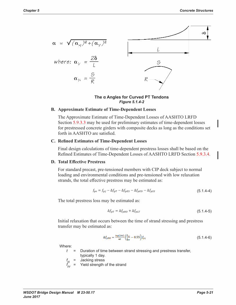
When summing the α angles for total friction loss along the structure, horizontal curvature of the tendons as well as horizontal and vertical roadway curvature shallbeincludedinthesummation.Theα angles for horizontally and vertically curved tendons are shown in Figure 5.1.4-2.
Chapter 5 Concrete Structures
WSDOT Bridge Design Manual M 23-50.17 Page 5-21 June 2017
The α Angles for Curved PT TendonsFigure 5.1.4-2
B. Approximate Estimate of Time-Dependent Losses
The Approximate Estimate of Time-Dependent Losses of AASHTO LRFD Section 5.9.3.3maybeusedforpreliminary estimates of time-dependent losses for prestressed concrete girders with composite decks as long as the conditions set forthinAASHTOaresatisfied.
C. Refined Estimates of Time-Dependent Losses
Finaldesigncalculationsoftime-dependentprestresslossesshallbebasedontheRefinedEstimatesofTime-DependentLossesofAASHTOLRFD Section 5.9.3.4.
D. Total Effective Prestress
Forstandardprecast,pre-tensionedmemberswithCIPdecksubjecttonormalloading and environmental conditions and pre-tensioned with low relaxation strands,thetotaleffectiveprestressmaybeestimatedas:
𝑓𝑓𝑝𝑝𝑝𝑝 = 𝑓𝑓𝑝𝑝𝑝𝑝 − ∆𝑓𝑓𝑝𝑝𝑝𝑝 − ∆𝑓𝑓𝑝𝑝𝑝𝑝𝑝𝑝 − ∆𝑓𝑓𝑝𝑝𝑝𝑝𝑝𝑝 − ∆𝑓𝑓𝑝𝑝𝑝𝑝𝑝𝑝 (5 .1 .4-4)
tThetotalprestresslossmaybe estimatedas:∆𝑓𝑓𝑝𝑝𝑝𝑝 = ∆𝑓𝑓𝑝𝑝𝑝𝑝𝑝𝑝 + ∆𝑓𝑓𝑝𝑝𝐿𝐿𝑝𝑝 (5 .1 .4-5)
The first term relates to iInitialrelaxationthatoccursbetweenthetimeofstrandstressingandprestresstransfer maybeestimatedas:.
(5 .1 .4-56)
Where:t = Durationoftimebetweenstrandstressingandprestresstransfer,typically1day.fpj = Jacking stressfpy = Yield strength of the strand
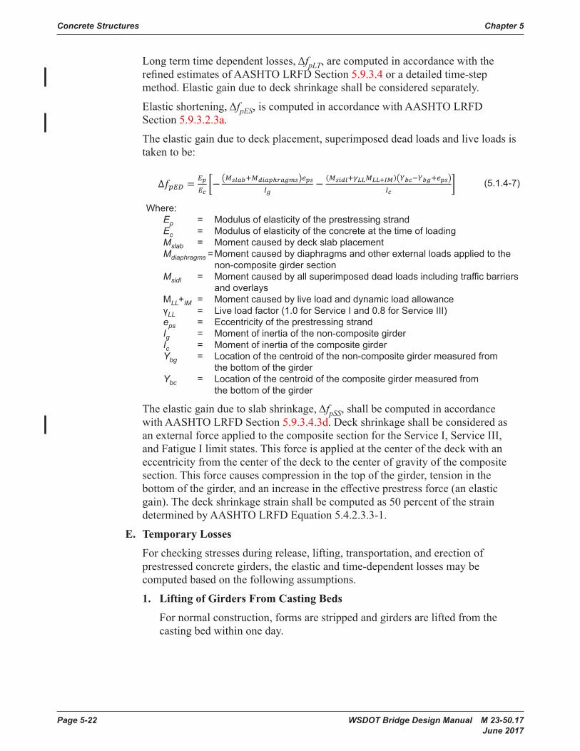
Long term time dependent losses, ΔfpLT, are computed in accordance with the refined estimates of AASHTO LRFD 5.9.5.4 or a detailed time-step method. Elastic gain due to deck shrinkage shallbeconsidered separately.
Elastic shortening, The second term, ΔfpES,, accounts for elastic shortening and is computed in accordance with AASHTO LRFD 5.9.5.2.3a.
The elastic gain due to deck placement, and superimposed dead loads and live loads istakentobe:
∆𝑓𝑓𝑝𝑝𝑝𝑝𝑝𝑝 = 𝑝𝑝𝑝𝑝𝑝𝑝𝑐𝑐�− �𝑀𝑀𝑠𝑠𝑠𝑠𝑠𝑠𝑠𝑠+𝑀𝑀𝑑𝑑𝑑𝑑𝑠𝑠𝑝𝑝ℎ𝑟𝑟𝑠𝑠𝑟𝑟𝑟𝑟𝑠𝑠�𝑝𝑝𝑝𝑝𝑠𝑠
𝐼𝐼𝑟𝑟−
(𝑀𝑀𝑠𝑠𝑑𝑑𝑑𝑑𝑠𝑠+𝛾𝛾𝐿𝐿𝐿𝐿𝑀𝑀𝐿𝐿𝐿𝐿+𝐼𝐼𝐼𝐼)�𝑌𝑌𝑠𝑠𝑐𝑐−𝑌𝑌𝑠𝑠𝑟𝑟+𝑝𝑝𝑝𝑝𝑠𝑠�𝐼𝐼𝑐𝑐
�
(5 .1 .4-67)
Where:Ep = Modulus of elasticity of the prestressing strandEc = Modulus of elasticity of the concrete at the time of loadingMslab = MomentcausedbydeckslabplacementMdiaphragms = Momentcausedbydiaphragmsandotherexternalloadsappliedtothe
non-composite girder sectionMsidl = Momentcausedbyallsuperimposeddeadloadsincludingtrafficbarriers
and overlaysMLL+IM = Momentcausedbylive load and dynamic load allowanceγLL = Live load factor (1.0 for Service I and 0.8 for Service III)eps = Eccentricity of the prestressing strandIg = Moment of inertia of the non-composite girder
Formatted: Lowered by 11 pt
(5 .1 .4-4)
Thetotalprestresslossmaybeestimatedas:
𝑓𝑓𝑝𝑝𝑝𝑝 = 𝑓𝑓𝑝𝑝𝑝𝑝 − ∆𝑓𝑓𝑝𝑝𝑝𝑝 − ∆𝑓𝑓𝑝𝑝𝑝𝑝𝑝𝑝 − ∆𝑓𝑓𝑝𝑝𝑝𝑝𝑝𝑝 − ∆𝑓𝑓𝑝𝑝𝑝𝑝𝑝𝑝 (5 .1 .4-4)
tThetotalprestresslossmaybe estimatedas:∆𝑓𝑓𝑝𝑝𝑝𝑝 = ∆𝑓𝑓𝑝𝑝𝑝𝑝𝑝𝑝 + ∆𝑓𝑓𝑝𝑝𝐿𝐿𝑝𝑝 (5 .1 .4-5)
The first term relates to iInitialrelaxationthatoccursbetweenthetimeofstrandstressingandprestresstransfer maybeestimatedas:.
(5 .1 .4-56)
Where:t = Durationoftimebetweenstrandstressingandprestresstransfer,typically1day.fpj = Jacking stressfpy = Yield strength of the strand
Long term time dependent losses, ΔfpLT, are computed in accordance with the refined estimates of AASHTO LRFD 5.9.5.4 or a detailed time-step method. Elastic gain due to deck shrinkage shallbeconsidered separately.
Elastic shortening, The second term, ΔfpES,, accounts for elastic shortening and is computed in accordance with AASHTO LRFD 5.9.5.2.3a.
The elastic gain due to deck placement, and superimposed dead loads and live loads istakentobe:
∆𝑓𝑓𝑝𝑝𝑝𝑝𝑝𝑝 = 𝑝𝑝𝑝𝑝𝑝𝑝𝑐𝑐�− �𝑀𝑀𝑠𝑠𝑠𝑠𝑠𝑠𝑠𝑠+𝑀𝑀𝑑𝑑𝑑𝑑𝑠𝑠𝑝𝑝ℎ𝑟𝑟𝑠𝑠𝑟𝑟𝑟𝑟𝑠𝑠�𝑝𝑝𝑝𝑝𝑠𝑠
𝐼𝐼𝑟𝑟−
(𝑀𝑀𝑠𝑠𝑑𝑑𝑑𝑑𝑠𝑠+𝛾𝛾𝐿𝐿𝐿𝐿𝑀𝑀𝐿𝐿𝐿𝐿+𝐼𝐼𝐼𝐼)�𝑌𝑌𝑠𝑠𝑐𝑐−𝑌𝑌𝑠𝑠𝑟𝑟+𝑝𝑝𝑝𝑝𝑠𝑠�𝐼𝐼𝑐𝑐
�
(5 .1 .4-67)
Where:Ep = Modulus of elasticity of the prestressing strandEc = Modulus of elasticity of the concrete at the time of loadingMslab = MomentcausedbydeckslabplacementMdiaphragms = Momentcausedbydiaphragmsandotherexternalloadsappliedtothe
non-composite girder sectionMsidl = Momentcausedbyallsuperimposeddeadloadsincludingtrafficbarriers
and overlaysMLL+IM = Momentcausedbylive load and dynamic load allowanceγLL = Live load factor (1.0 for Service I and 0.8 for Service III)eps = Eccentricity of the prestressing strandIg = Moment of inertia of the non-composite girder
Formatted: Lowered by 11 pt
(5 .1 .4-5)
Initialrelaxationthatoccursbetweenthetimeofstrandstressingandprestresstransfermaybeestimatedas:
𝑓𝑓𝑝𝑝𝑝𝑝 = 𝑓𝑓𝑝𝑝𝑝𝑝 − ∆𝑓𝑓𝑝𝑝𝑝𝑝 − ∆𝑓𝑓𝑝𝑝𝑝𝑝𝑝𝑝 − ∆𝑓𝑓𝑝𝑝𝑝𝑝𝑝𝑝 − ∆𝑓𝑓𝑝𝑝𝑝𝑝𝑝𝑝 (5 .1 .4-4)
tThetotalprestresslossmaybe estimatedas:∆𝑓𝑓𝑝𝑝𝑝𝑝 = ∆𝑓𝑓𝑝𝑝𝑝𝑝𝑝𝑝 + ∆𝑓𝑓𝑝𝑝𝐿𝐿𝑝𝑝 (5 .1 .4-5)
The first term relates to iInitialrelaxationthatoccursbetweenthetimeofstrandstressingandprestresstransfer maybeestimatedas:.
(5 .1 .4-56)
Where:t = Durationoftimebetweenstrandstressingandprestresstransfer,typically1day.fpj = Jacking stressfpy = Yield strength of the strand
Long term time dependent losses, ΔfpLT, are computed in accordance with the refined estimates of AASHTO LRFD 5.9.5.4 or a detailed time-step method. Elastic gain due to deck shrinkage shallbeconsidered separately.
Elastic shortening, The second term, ΔfpES,, accounts for elastic shortening and is computed in accordance with AASHTO LRFD 5.9.5.2.3a.
The elastic gain due to deck placement, and superimposed dead loads and live loads istakentobe:
∆𝑓𝑓𝑝𝑝𝑝𝑝𝑝𝑝 = 𝑝𝑝𝑝𝑝𝑝𝑝𝑐𝑐�− �𝑀𝑀𝑠𝑠𝑠𝑠𝑠𝑠𝑠𝑠+𝑀𝑀𝑑𝑑𝑑𝑑𝑠𝑠𝑝𝑝ℎ𝑟𝑟𝑠𝑠𝑟𝑟𝑟𝑟𝑠𝑠�𝑝𝑝𝑝𝑝𝑠𝑠
𝐼𝐼𝑟𝑟−
(𝑀𝑀𝑠𝑠𝑑𝑑𝑑𝑑𝑠𝑠+𝛾𝛾𝐿𝐿𝐿𝐿𝑀𝑀𝐿𝐿𝐿𝐿+𝐼𝐼𝐼𝐼)�𝑌𝑌𝑠𝑠𝑐𝑐−𝑌𝑌𝑠𝑠𝑟𝑟+𝑝𝑝𝑝𝑝𝑠𝑠�𝐼𝐼𝑐𝑐
�
(5 .1 .4-67)
Where:Ep = Modulus of elasticity of the prestressing strandEc = Modulus of elasticity of the concrete at the time of loadingMslab = MomentcausedbydeckslabplacementMdiaphragms = Momentcausedbydiaphragmsandotherexternalloadsappliedtothe
non-composite girder sectionMsidl = Momentcausedbyallsuperimposeddeadloadsincludingtrafficbarriers
and overlaysMLL+IM = Momentcausedbylive load and dynamic load allowanceγLL = Live load factor (1.0 for Service I and 0.8 for Service III)eps = Eccentricity of the prestressing strandIg = Moment of inertia of the non-composite girder
Formatted: Lowered by 11 pt
(5 .1 .4-6)
Where: t = Duration of time between strand stressing and prestress transfer, typically 1 day . fpj = Jacking stress fpy = Yield strength of the strand
Concrete Structures Chapter 5
Page 5-22 WSDOT Bridge Design Manual M 23-50.17 June 2017
Longtermtimedependentlosses,ΔfpLT, are computed in accordance with the refinedestimatesofAASHTOLRFD Section 5.9.3.4 or a detailed time-step method.Elasticgainduetodeckshrinkageshallbeconsideredseparately.
Elasticshortening,ΔfpES, is computed in accordance with AASHTO LRFD Section 5.9.3.2.3a.
The elastic gain due to deck placement, superimposed dead loads and live loads is takentobe:
∆𝑓𝑓𝑝𝑝𝑝𝑝𝑝𝑝 = 𝑝𝑝𝑝𝑝𝑝𝑝𝑐𝑐�− �𝑀𝑀𝑠𝑠𝑠𝑠𝑠𝑠𝑠𝑠+𝑀𝑀𝑑𝑑𝑑𝑑𝑠𝑠𝑝𝑝ℎ𝑟𝑟𝑠𝑠𝑟𝑟𝑟𝑟𝑠𝑠�𝑒𝑒𝑝𝑝𝑠𝑠
𝐼𝐼𝑟𝑟−
(𝑀𝑀𝑠𝑠𝑑𝑑𝑑𝑑𝑠𝑠+𝛾𝛾𝐿𝐿𝐿𝐿𝑀𝑀𝐿𝐿𝐿𝐿+𝐼𝐼𝐼𝐼)�𝑌𝑌𝑠𝑠𝑐𝑐−𝑌𝑌𝑠𝑠𝑟𝑟+𝑒𝑒𝑝𝑝𝑠𝑠�𝐼𝐼𝑐𝑐
� (5 .1 .4-7)
Where:Ep = Modulus of elasticity of the prestressing strandEc = Modulus of elasticity of the concrete at the time of loadingMslab = MomentcausedbydeckslabplacementMdiaphragms = Momentcausedbydiaphragmsandotherexternalloadsappliedtothe
non-composite girder sectionMsidl = Momentcausedbyallsuperimposeddeadloadsincludingtrafficbarriers
and overlaysMLL+IM = Momentcausedbylive load and dynamic load allowanceγLL = Live load factor (1.0 for Service I and 0.8 for Service III)eps = Eccentricity of the prestressing strandIg = Moment of inertia of the non-composite girderIc = Moment of inertia of the composite girderYbg = Location of the centroid of the non-compositegirdermeasuredfromthebottom
of the girderYbc = Locationofthecentroidofthecompositegirdermeasuredfromthebottom
of the girder
Theelasticgainduetoslabshrinkage,ΔfpSS, shallbe computed in accordance with AASHTO LRFD 5.9.5.4.3d. Deckshrinkageshallbe considered as an external force applied to the composite section for the Service I, Service III, and Fatigue I limit states. This force is applied at the center of the deck with an eccentricity from the center of the deck to the center of gravity of the composite section. Thisforcecausescompressioninthetopofthegirder,tensioninthebottomofthegirder,andanincreaseintheeffectiveprestressforce(anelasticgain).Thedeckshrinkagestrainshallbecomputedas50%ofthestraindeterminedbyAASHTO LRFD Equation 5.4.2.3.3-1.
E. Temporary Losses – For checking stresses during release, lifting, transportation, and erection of prestressed girders, the elastic and time-dependentlossesmaybecomputedbasedonthefollowing assumptions.
1. Lifting of Girders From Casting Beds – For normal construction, forms are stripped and girders areliftedfromthecastingbedwithinone day.
2. Transportation – Girders are most difficult to transport at a young age. The hauling configuration causesreduceddeadloadmomentsinthegirderandthepotentialforoverstressbetweentheharping points. Overstress may also occur at the support points depending on the prestressing and thetruckingconfiguration.Thisiscompoundedbythe magnitude of the prestress force not having beenreducedbylosses.Foranaggressiveconstructionschedulegirdersaretypicallytransportedtothejobsitearoundday 10.
WhenlossesareestimatedbytheApproximateEstimateofAASHTOLRFD5.9.5.3,the losses at thetimeofhaulingmaybeestimatedby:
(5 .1 .4-7)
(5 .1 .4-7)
Where: Ep = Modulus of elasticity of the prestressing strand Ec = Modulus of elasticity of the concrete at the time of loading Mslab = Moment caused by deck slab placement Mdiaphragms = Moment caused by diaphragms and other external loads applied to the non-composite girder section Msidl = Moment caused by all superimposed dead loads including traffic barriers and overlays MLL+IM = Moment caused by live load and dynamic load allowance γLL = Live load factor (1 .0 for Service I and 0 .8 for Service III) eps = Eccentricity of the prestressing strand Ig = Moment of inertia of the non-composite girder Ic = Moment of inertia of the composite girder Ybg = Location of the centroid of the non-composite girder measured from the bottom of the girder Ybc = Location of the centroid of the composite girder measured from the bottom of the girder
Theelasticgainduetoslabshrinkage,ΔfpSS,shallbecomputedinaccordancewith AASHTO LRFD Section 5.9.3.4.3d.Deckshrinkageshallbeconsideredasan external force applied to the composite section for the Service I, Service III, and Fatigue I limit states. This force is applied at the center of the deck with an eccentricity from the center of the deck to the center of gravity of the composite section. This force causes compression in the top of the girder, tension in the bottomofthegirder,andanincreaseintheeffectiveprestressforce(anelasticgain).Thedeckshrinkagestrainshallbecomputedas50percentofthestraindeterminedbyAASHTOLRFDEquation5.4.2.3.3-1.
E. Temporary Losses
For checking stresses during release, lifting, transportation, and erection of prestressedconcretegirders,theelasticandtime-dependentlossesmaybecomputedbasedonthefollowingassumptions.
1. Lifting of Girders From Casting Beds
For normal construction, forms are stripped and girders are lifted from the castingbedwithinoneday.

Chapter 5 Concrete Structures
WSDOT Bridge Design Manual M 23-50.17 Page 5-23 June 2017
2. Transportation
Girdersaremostdifficulttotransportatayoungage.Thehaulingconfigurationcauses reduced dead load moments in the girder and the potential for overstressbetweentheharpingpoints.Overstressmayalsooccuratthesupportpointsdependingontheprestressingandthetruckingconfiguration.Thisiscompoundedbythemagnitudeoftheprestressforcenothavingbeenreducedbylosses.Foranaggressiveconstructionschedulegirdersaretypicallytransportedtothejobsitearoundday10.
Whenlossesareestimatedbythe Approximate Estimate of AASHTO LRFD Section 5.9.3.3,thelossesatthetimeofhaulingmaybeestimatedby:
(5 .1 .4-8)
Where:ΔfpTH = total loss at haulingΔfpH = time dependent loss at time of hauling =
(5 .1 .4-8)
Where: ΔfpTH = total loss at hauling ΔfpH = time dependent loss at time of hauling =
(5 .1 .4-8)
Where:ΔfpTH = total loss at haulingΔfpH = time dependent loss at time of hauling =
3. Erection
During construction the non-composite girders must carry the full weight of the deckslabandinteriordiaphragms.Thisloadingtypicallyoccursaround120days for a normal construction schedule.
4. Final Configuration
Thecompositeslabandgirdersectionmustcarryallconceivableloadsincludingsuperimposeddeadloadssuchastrafficbarriers,overlays,andliveloads. It is assumed that superimposed dead loads are placed at 120 days and finallossesoccurat2,000days.
5.1.5 Prestressing Anchorage SystemsTherearenumerousprestressingsystems.Mostsystemscombineamethodofprestressing the strands with a method of anchoring it to concrete.
WSDOTrequiresapprovalofallmulti-strandand/orbaranchoragesusedinprestressedconcretebridgesasdescribedinStandard Specifications Section 6-02.3(26).
5.1.6 Post-Tensioning DuctsPost-tensioning ducts shall meet the requirements of Standard Specifications Section 6-02.3(26)E.
Ducts for longitudinal post-tensioning tendons in spliced prestressed concrete I-girders shallbemadeofrigidgalvanizedspiral ferrous metal to maintain standard girder concrete cover requirements.
Concrete Structures Chapter 5
Page 5-24 WSDOT Bridge Design Manual M 23-50.17 June 2017
5.2 Design Considerations5.2.1 Service and Fatigue Limit States
A. General
Servicelimitstateisusedtosatisfyallowablestresses,deflection,andcontrolofcracking requirements. Design aids for tensile stress in reinforcement at the service limitstate,ƒ
ss, are provided in Appendices 5.2-A1, 5.2-A2, and 5.2-A3.
B. Control of Cracking
Reinforcementshallbeprovidedandspacedtomeettherequirementsin AASHTO LRFD Section 5.6.7“ControlofCrackingbyDistributionofReinforcement.”TheexposurefactorshallbebaseduponaClass2exposure condition.
C. Allowable Stresses in Prestressed Concrete Members
AllowableconcretestressesfortheserviceandfatiguelimitstatesareshowninTable5.2.1-1.Forprestressedconcretegirders,theallowableconcretestressesshallbesatisfiedatallstagesofgirderconstructionandinserviceinaccordancewithSection5.6.2.C.Thetensilestressintheprecompressedtensilezoneforthefinalservice load condition (Service III) is limited to zero. This prevents cracking of the concrete during the service life of the structure and provides additional stress and strength capacity for overloads.
Forallowabletensilestressesthatrequirebondedreinforcementsufficienttoresistthetensileforceintheconcrete,thetensileforceshallbecomputedusingtheprocedureillustratedinAASHTOLRFDC5.9.2.3.1bassuminganuncrackedsection.Thebondedreinforcementisproportionedusingastressof0.5fy, not to exceed30ksi.Individualreinforcingbarsareonlyconsiderediftheyarefullydevelopedandarelocatedwithinthetensilestressregionofthemember.
Thevariableλistheconcretedensitymodificationfactorcalculatedinaccordancewith AASHTO LRFD Section 5.4.2.8.

Chapter 5 Concrete Structures
WSDOT Bridge Design Manual M 23-50.17 Page 5-25 June 2017
Condition Stress Location Allowable Stress (ksi)
Temporary Stress at
Transfer and Lifting from Casting Bed
Tensile
In areas without bonded reinforcement sufficient to resist the tensile force in the concrete
WSDOT Bridge Design Manual M 23-50.16June 2016
Page 5-1
Condition Stress Location Allowable Stress (ksi) Temporary Stress at Transfer and Lifting from Casting Bed
Tensile In areas without bonded reinforcement sufficient to resist the tensile force in the concrete 0.0948𝜆𝜆𝜆𝜆�𝑓𝑓𝑓𝑓𝑐𝑐𝑐𝑐𝑐𝑐𝑐𝑐′ ≤ 0.2
In areas with bonded reinforcement sufficient to resist the tensile force in the concrete 0.24𝜆𝜆𝜆𝜆�𝑓𝑓𝑓𝑓𝑐𝑐𝑐𝑐𝑐𝑐𝑐𝑐′
Compressive All locations 0.65𝑓𝑓𝑓𝑓𝑐𝑐𝑐𝑐𝑐𝑐𝑐𝑐′
Temporary Stress at Shipping and Erection
Tensile In areas without bonded reinforcement sufficient to resist the tensile force in the concrete
0.0948𝜆𝜆𝜆𝜆�𝑓𝑓𝑓𝑓𝑐𝑐𝑐𝑐′ ≤ 0.2
In areas with bonded reinforcement sufficient to resist the tensile force in the concrete
0.19𝜆𝜆𝜆𝜆�𝑓𝑓𝑓𝑓𝑐𝑐𝑐𝑐′
In areas with bonded reinforcement sufficient to resist the tensile force in the concrete when shipping at 6% superelevation, without impact (see Section 5.6.2.C.2.d)
0.24𝜆𝜆𝜆𝜆�𝑓𝑓𝑓𝑓𝑐𝑐𝑐𝑐′
Compressive All locations 0.65𝑓𝑓𝑓𝑓𝑐𝑐𝑐𝑐′ Final Stresses at Service Load
Tensile Precompressed tensile zone 0.0 Compressive Effective prestress and permanent loads 0.45𝑓𝑓𝑓𝑓𝑐𝑐𝑐𝑐′
Effective prestress, permanent loads and transient (live) loads
0.60𝑓𝑓𝑓𝑓𝑐𝑐𝑐𝑐′
Final Stresses at Fatigue Load
Compressive Fatigue I Load Combination plus one-half effective prestress and permanent loads in accordance with AASHTO LRFD Section 5.5.3.1
0.40𝑓𝑓𝑓𝑓𝑐𝑐𝑐𝑐′
Allowable Stresses in Prestressed Concrete Members
Table 5.2.1-1
In areas with bonded reinforcement sufficient to resist the tensile force in the concrete
WSDOT Bridge Design Manual M 23-50.16June 2016
Page 5-1
Condition Stress Location Allowable Stress (ksi) Temporary Stress at Transfer and Lifting from Casting Bed
Tensile In areas without bonded reinforcement sufficient to resist the tensile force in the concrete 0.0948𝜆𝜆𝜆𝜆�𝑓𝑓𝑓𝑓𝑐𝑐𝑐𝑐𝑐𝑐𝑐𝑐′ ≤ 0.2
In areas with bonded reinforcement sufficient to resist the tensile force in the concrete 0.24𝜆𝜆𝜆𝜆�𝑓𝑓𝑓𝑓𝑐𝑐𝑐𝑐𝑐𝑐𝑐𝑐′
Compressive All locations 0.65𝑓𝑓𝑓𝑓𝑐𝑐𝑐𝑐𝑐𝑐𝑐𝑐′
Temporary Stress at Shipping and Erection
Tensile In areas without bonded reinforcement sufficient to resist the tensile force in the concrete
0.0948𝜆𝜆𝜆𝜆�𝑓𝑓𝑓𝑓𝑐𝑐𝑐𝑐′ ≤ 0.2
In areas with bonded reinforcement sufficient to resist the tensile force in the concrete
0.19𝜆𝜆𝜆𝜆�𝑓𝑓𝑓𝑓𝑐𝑐𝑐𝑐′
In areas with bonded reinforcement sufficient to resist the tensile force in the concrete when shipping at 6% superelevation, without impact (see Section 5.6.2.C.2.d)
0.24𝜆𝜆𝜆𝜆�𝑓𝑓𝑓𝑓𝑐𝑐𝑐𝑐′
Compressive All locations 0.65𝑓𝑓𝑓𝑓𝑐𝑐𝑐𝑐′ Final Stresses at Service Load
Tensile Precompressed tensile zone 0.0 Compressive Effective prestress and permanent loads 0.45𝑓𝑓𝑓𝑓𝑐𝑐𝑐𝑐′
Effective prestress, permanent loads and transient (live) loads
0.60𝑓𝑓𝑓𝑓𝑐𝑐𝑐𝑐′
Final Stresses at Fatigue Load
Compressive Fatigue I Load Combination plus one-half effective prestress and permanent loads in accordance with AASHTO LRFD Section 5.5.3.1
0.40𝑓𝑓𝑓𝑓𝑐𝑐𝑐𝑐′
Allowable Stresses in Prestressed Concrete Members
Table 5.2.1-1
Compressive All locations
WSDOT Bridge Design Manual M 23-50.16June 2016
Page 5-1
Condition Stress Location Allowable Stress (ksi) Temporary Stress at Transfer and Lifting from Casting Bed
Tensile In areas without bonded reinforcement sufficient to resist the tensile force in the concrete 0.0948𝜆𝜆𝜆𝜆�𝑓𝑓𝑓𝑓𝑐𝑐𝑐𝑐𝑐𝑐𝑐𝑐′ ≤ 0.2
In areas with bonded reinforcement sufficient to resist the tensile force in the concrete 0.24𝜆𝜆𝜆𝜆�𝑓𝑓𝑓𝑓𝑐𝑐𝑐𝑐𝑐𝑐𝑐𝑐′
Compressive All locations 0.65𝑓𝑓𝑓𝑓𝑐𝑐𝑐𝑐𝑐𝑐𝑐𝑐′
Temporary Stress at Shipping and Erection
Tensile In areas without bonded reinforcement sufficient to resist the tensile force in the concrete
0.0948𝜆𝜆𝜆𝜆�𝑓𝑓𝑓𝑓𝑐𝑐𝑐𝑐′ ≤ 0.2
In areas with bonded reinforcement sufficient to resist the tensile force in the concrete
0.19𝜆𝜆𝜆𝜆�𝑓𝑓𝑓𝑓𝑐𝑐𝑐𝑐′
In areas with bonded reinforcement sufficient to resist the tensile force in the concrete when shipping at 6% superelevation, without impact (see Section 5.6.2.C.2.d)
0.24𝜆𝜆𝜆𝜆�𝑓𝑓𝑓𝑓𝑐𝑐𝑐𝑐′
Compressive All locations 0.65𝑓𝑓𝑓𝑓𝑐𝑐𝑐𝑐′ Final Stresses at Service Load
Tensile Precompressed tensile zone 0.0 Compressive Effective prestress and permanent loads 0.45𝑓𝑓𝑓𝑓𝑐𝑐𝑐𝑐′
Effective prestress, permanent loads and transient (live) loads
0.60𝑓𝑓𝑓𝑓𝑐𝑐𝑐𝑐′
Final Stresses at Fatigue Load
Compressive Fatigue I Load Combination plus one-half effective prestress and permanent loads in accordance with AASHTO LRFD Section 5.5.3.1
0.40𝑓𝑓𝑓𝑓𝑐𝑐𝑐𝑐′
Allowable Stresses in Prestressed Concrete Members
Table 5.2.1-1
Temporary Stress at
Shipping and Erection
Tensile
In areas without bonded reinforcement sufficient to resist the tensile force in the concrete
WSDOT Bridge Design Manual M 23-50.16June 2016
Page 5-1
Condition Stress Location Allowable Stress (ksi) Temporary Stress at Transfer and Lifting from Casting Bed
Tensile In areas without bonded reinforcement sufficient to resist the tensile force in the concrete 0.0948𝜆𝜆𝜆𝜆�𝑓𝑓𝑓𝑓𝑐𝑐𝑐𝑐𝑐𝑐𝑐𝑐′ ≤ 0.2
In areas with bonded reinforcement sufficient to resist the tensile force in the concrete 0.24𝜆𝜆𝜆𝜆�𝑓𝑓𝑓𝑓𝑐𝑐𝑐𝑐𝑐𝑐𝑐𝑐′
Compressive All locations 0.65𝑓𝑓𝑓𝑓𝑐𝑐𝑐𝑐𝑐𝑐𝑐𝑐′
Temporary Stress at Shipping and Erection
Tensile In areas without bonded reinforcement sufficient to resist the tensile force in the concrete
0.0948𝜆𝜆𝜆𝜆�𝑓𝑓𝑓𝑓𝑐𝑐𝑐𝑐′ ≤ 0.2
In areas with bonded reinforcement sufficient to resist the tensile force in the concrete
0.19𝜆𝜆𝜆𝜆�𝑓𝑓𝑓𝑓𝑐𝑐𝑐𝑐′
In areas with bonded reinforcement sufficient to resist the tensile force in the concrete when shipping at 6% superelevation, without impact (see Section 5.6.2.C.2.d)
0.24𝜆𝜆𝜆𝜆�𝑓𝑓𝑓𝑓𝑐𝑐𝑐𝑐′
Compressive All locations 0.65𝑓𝑓𝑓𝑓𝑐𝑐𝑐𝑐′ Final Stresses at Service Load
Tensile Precompressed tensile zone 0.0 Compressive Effective prestress and permanent loads 0.45𝑓𝑓𝑓𝑓𝑐𝑐𝑐𝑐′
Effective prestress, permanent loads and transient (live) loads
0.60𝑓𝑓𝑓𝑓𝑐𝑐𝑐𝑐′
Final Stresses at Fatigue Load
Compressive Fatigue I Load Combination plus one-half effective prestress and permanent loads in accordance with AASHTO LRFD Section 5.5.3.1
0.40𝑓𝑓𝑓𝑓𝑐𝑐𝑐𝑐′
Allowable Stresses in Prestressed Concrete Members
Table 5.2.1-1
In areas with bonded reinforcement sufficient to resist the tensile force in the concrete
WSDOT Bridge Design Manual M 23-50.16June 2016
Page 5-1
Condition Stress Location Allowable Stress (ksi) Temporary Stress at Transfer and Lifting from Casting Bed
Tensile In areas without bonded reinforcement sufficient to resist the tensile force in the concrete 0.0948𝜆𝜆𝜆𝜆�𝑓𝑓𝑓𝑓𝑐𝑐𝑐𝑐𝑐𝑐𝑐𝑐′ ≤ 0.2
In areas with bonded reinforcement sufficient to resist the tensile force in the concrete 0.24𝜆𝜆𝜆𝜆�𝑓𝑓𝑓𝑓𝑐𝑐𝑐𝑐𝑐𝑐𝑐𝑐′
Compressive All locations 0.65𝑓𝑓𝑓𝑓𝑐𝑐𝑐𝑐𝑐𝑐𝑐𝑐′
Temporary Stress at Shipping and Erection
Tensile In areas without bonded reinforcement sufficient to resist the tensile force in the concrete
0.0948𝜆𝜆𝜆𝜆�𝑓𝑓𝑓𝑓𝑐𝑐𝑐𝑐′ ≤ 0.2
In areas with bonded reinforcement sufficient to resist the tensile force in the concrete
0.19𝜆𝜆𝜆𝜆�𝑓𝑓𝑓𝑓𝑐𝑐𝑐𝑐′
In areas with bonded reinforcement sufficient to resist the tensile force in the concrete when shipping at 6% superelevation, without impact (see Section 5.6.2.C.2.d)
0.24𝜆𝜆𝜆𝜆�𝑓𝑓𝑓𝑓𝑐𝑐𝑐𝑐′
Compressive All locations 0.65𝑓𝑓𝑓𝑓𝑐𝑐𝑐𝑐′ Final Stresses at Service Load
Tensile Precompressed tensile zone 0.0 Compressive Effective prestress and permanent loads 0.45𝑓𝑓𝑓𝑓𝑐𝑐𝑐𝑐′
Effective prestress, permanent loads and transient (live) loads
0.60𝑓𝑓𝑓𝑓𝑐𝑐𝑐𝑐′
Final Stresses at Fatigue Load
Compressive Fatigue I Load Combination plus one-half effective prestress and permanent loads in accordance with AASHTO LRFD Section 5.5.3.1
0.40𝑓𝑓𝑓𝑓𝑐𝑐𝑐𝑐′
Allowable Stresses in Prestressed Concrete Members
Table 5.2.1-1
In areas with bonded reinforcement sufficient to resist the tensile force in the concrete when shipping at 6% superelevation, without impact (see Section 5 .6 .2 .C .2 .d)
WSDOT Bridge Design Manual M 23-50.16June 2016
Page 5-1
Condition Stress Location Allowable Stress (ksi) Temporary Stress at Transfer and Lifting from Casting Bed
Tensile In areas without bonded reinforcement sufficient to resist the tensile force in the concrete 0.0948𝜆𝜆𝜆𝜆�𝑓𝑓𝑓𝑓𝑐𝑐𝑐𝑐𝑐𝑐𝑐𝑐′ ≤ 0.2
In areas with bonded reinforcement sufficient to resist the tensile force in the concrete 0.24𝜆𝜆𝜆𝜆�𝑓𝑓𝑓𝑓𝑐𝑐𝑐𝑐𝑐𝑐𝑐𝑐′
Compressive All locations 0.65𝑓𝑓𝑓𝑓𝑐𝑐𝑐𝑐𝑐𝑐𝑐𝑐′
Temporary Stress at Shipping and Erection
Tensile In areas without bonded reinforcement sufficient to resist the tensile force in the concrete
0.0948𝜆𝜆𝜆𝜆�𝑓𝑓𝑓𝑓𝑐𝑐𝑐𝑐′ ≤ 0.2
In areas with bonded reinforcement sufficient to resist the tensile force in the concrete
0.19𝜆𝜆𝜆𝜆�𝑓𝑓𝑓𝑓𝑐𝑐𝑐𝑐′
In areas with bonded reinforcement sufficient to resist the tensile force in the concrete when shipping at 6% superelevation, without impact (see Section 5.6.2.C.2.d)
0.24𝜆𝜆𝜆𝜆�𝑓𝑓𝑓𝑓𝑐𝑐𝑐𝑐′
Compressive All locations 0.65𝑓𝑓𝑓𝑓𝑐𝑐𝑐𝑐′ Final Stresses at Service Load
Tensile Precompressed tensile zone 0.0 Compressive Effective prestress and permanent loads 0.45𝑓𝑓𝑓𝑓𝑐𝑐𝑐𝑐′
Effective prestress, permanent loads and transient (live) loads
0.60𝑓𝑓𝑓𝑓𝑐𝑐𝑐𝑐′
Final Stresses at Fatigue Load
Compressive Fatigue I Load Combination plus one-half effective prestress and permanent loads in accordance with AASHTO LRFD Section 5.5.3.1
0.40𝑓𝑓𝑓𝑓𝑐𝑐𝑐𝑐′
Allowable Stresses in Prestressed Concrete Members
Table 5.2.1-1
Compressive All locations
WSDOT Bridge Design Manual M 23-50.16June 2016
Page 5-1
Condition Stress Location Allowable Stress (ksi) Temporary Stress at Transfer and Lifting from Casting Bed
Tensile In areas without bonded reinforcement sufficient to resist the tensile force in the concrete 0.0948𝜆𝜆𝜆𝜆�𝑓𝑓𝑓𝑓𝑐𝑐𝑐𝑐𝑐𝑐𝑐𝑐′ ≤ 0.2
In areas with bonded reinforcement sufficient to resist the tensile force in the concrete 0.24𝜆𝜆𝜆𝜆�𝑓𝑓𝑓𝑓𝑐𝑐𝑐𝑐𝑐𝑐𝑐𝑐′
Compressive All locations 0.65𝑓𝑓𝑓𝑓𝑐𝑐𝑐𝑐𝑐𝑐𝑐𝑐′
Temporary Stress at Shipping and Erection
Tensile In areas without bonded reinforcement sufficient to resist the tensile force in the concrete
0.0948𝜆𝜆𝜆𝜆�𝑓𝑓𝑓𝑓𝑐𝑐𝑐𝑐′ ≤ 0.2
In areas with bonded reinforcement sufficient to resist the tensile force in the concrete
0.19𝜆𝜆𝜆𝜆�𝑓𝑓𝑓𝑓𝑐𝑐𝑐𝑐′
In areas with bonded reinforcement sufficient to resist the tensile force in the concrete when shipping at 6% superelevation, without impact (see Section 5.6.2.C.2.d)
0.24𝜆𝜆𝜆𝜆�𝑓𝑓𝑓𝑓𝑐𝑐𝑐𝑐′
Compressive All locations 0.65𝑓𝑓𝑓𝑓𝑐𝑐𝑐𝑐′ Final Stresses at Service Load
Tensile Precompressed tensile zone 0.0 Compressive Effective prestress and permanent loads 0.45𝑓𝑓𝑓𝑓𝑐𝑐𝑐𝑐′
Effective prestress, permanent loads and transient (live) loads
0.60𝑓𝑓𝑓𝑓𝑐𝑐𝑐𝑐′
Final Stresses at Fatigue Load
Compressive Fatigue I Load Combination plus one-half effective prestress and permanent loads in accordance with AASHTO LRFD Section 5.5.3.1
0.40𝑓𝑓𝑓𝑓𝑐𝑐𝑐𝑐′
Allowable Stresses in Prestressed Concrete Members
Table 5.2.1-1
Final Stresses at Service
Load
Tensile Precompressed tensile zone
WSDOT Bridge Design Manual M 23-50.16June 2016
Page 5-1
Condition Stress Location Allowable Stress (ksi) Temporary Stress at Transfer and Lifting from Casting Bed
Tensile In areas without bonded reinforcement sufficient to resist the tensile force in the concrete 0.0948𝜆𝜆𝜆𝜆�𝑓𝑓𝑓𝑓𝑐𝑐𝑐𝑐𝑐𝑐𝑐𝑐′ ≤ 0.2
In areas with bonded reinforcement sufficient to resist the tensile force in the concrete 0.24𝜆𝜆𝜆𝜆�𝑓𝑓𝑓𝑓𝑐𝑐𝑐𝑐𝑐𝑐𝑐𝑐′
Compressive All locations 0.65𝑓𝑓𝑓𝑓𝑐𝑐𝑐𝑐𝑐𝑐𝑐𝑐′
Temporary Stress at Shipping and Erection
Tensile In areas without bonded reinforcement sufficient to resist the tensile force in the concrete
0.0948𝜆𝜆𝜆𝜆�𝑓𝑓𝑓𝑓𝑐𝑐𝑐𝑐′ ≤ 0.2
In areas with bonded reinforcement sufficient to resist the tensile force in the concrete
0.19𝜆𝜆𝜆𝜆�𝑓𝑓𝑓𝑓𝑐𝑐𝑐𝑐′
In areas with bonded reinforcement sufficient to resist the tensile force in the concrete when shipping at 6% superelevation, without impact (see Section 5.6.2.C.2.d)
0.24𝜆𝜆𝜆𝜆�𝑓𝑓𝑓𝑓𝑐𝑐𝑐𝑐′
Compressive All locations 0.65𝑓𝑓𝑓𝑓𝑐𝑐𝑐𝑐′ Final Stresses at Service Load
Tensile Precompressed tensile zone 0.0 Compressive Effective prestress and permanent loads 0.45𝑓𝑓𝑓𝑓𝑐𝑐𝑐𝑐′
Effective prestress, permanent loads and transient (live) loads
0.60𝑓𝑓𝑓𝑓𝑐𝑐𝑐𝑐′
Final Stresses at Fatigue Load
Compressive Fatigue I Load Combination plus one-half effective prestress and permanent loads in accordance with AASHTO LRFD Section 5.5.3.1
0.40𝑓𝑓𝑓𝑓𝑐𝑐𝑐𝑐′
Allowable Stresses in Prestressed Concrete Members
Table 5.2.1-1
CompressiveEffective prestress and permanent loads
WSDOT Bridge Design Manual M 23-50.16June 2016
Page 5-1
Condition Stress Location Allowable Stress (ksi) Temporary Stress at Transfer and Lifting from Casting Bed
Tensile In areas without bonded reinforcement sufficient to resist the tensile force in the concrete 0.0948𝜆𝜆𝜆𝜆�𝑓𝑓𝑓𝑓𝑐𝑐𝑐𝑐𝑐𝑐𝑐𝑐′ ≤ 0.2
In areas with bonded reinforcement sufficient to resist the tensile force in the concrete 0.24𝜆𝜆𝜆𝜆�𝑓𝑓𝑓𝑓𝑐𝑐𝑐𝑐𝑐𝑐𝑐𝑐′
Compressive All locations 0.65𝑓𝑓𝑓𝑓𝑐𝑐𝑐𝑐𝑐𝑐𝑐𝑐′
Temporary Stress at Shipping and Erection
Tensile In areas without bonded reinforcement sufficient to resist the tensile force in the concrete
0.0948𝜆𝜆𝜆𝜆�𝑓𝑓𝑓𝑓𝑐𝑐𝑐𝑐′ ≤ 0.2
In areas with bonded reinforcement sufficient to resist the tensile force in the concrete
0.19𝜆𝜆𝜆𝜆�𝑓𝑓𝑓𝑓𝑐𝑐𝑐𝑐′
In areas with bonded reinforcement sufficient to resist the tensile force in the concrete when shipping at 6% superelevation, without impact (see Section 5.6.2.C.2.d)
0.24𝜆𝜆𝜆𝜆�𝑓𝑓𝑓𝑓𝑐𝑐𝑐𝑐′
Compressive All locations 0.65𝑓𝑓𝑓𝑓𝑐𝑐𝑐𝑐′ Final Stresses at Service Load
Tensile Precompressed tensile zone 0.0 Compressive Effective prestress and permanent loads 0.45𝑓𝑓𝑓𝑓𝑐𝑐𝑐𝑐′
Effective prestress, permanent loads and transient (live) loads
0.60𝑓𝑓𝑓𝑓𝑐𝑐𝑐𝑐′
Final Stresses at Fatigue Load
Compressive Fatigue I Load Combination plus one-half effective prestress and permanent loads in accordance with AASHTO LRFD Section 5.5.3.1
0.40𝑓𝑓𝑓𝑓𝑐𝑐𝑐𝑐′
Allowable Stresses in Prestressed Concrete Members
Table 5.2.1-1
Effective prestress, permanent loads and transient (live) loads
WSDOT Bridge Design Manual M 23-50.16June 2016
Page 5-1
Condition Stress Location Allowable Stress (ksi) Temporary Stress at Transfer and Lifting from Casting Bed
Tensile In areas without bonded reinforcement sufficient to resist the tensile force in the concrete 0.0948𝜆𝜆𝜆𝜆�𝑓𝑓𝑓𝑓𝑐𝑐𝑐𝑐𝑐𝑐𝑐𝑐′ ≤ 0.2
In areas with bonded reinforcement sufficient to resist the tensile force in the concrete 0.24𝜆𝜆𝜆𝜆�𝑓𝑓𝑓𝑓𝑐𝑐𝑐𝑐𝑐𝑐𝑐𝑐′
Compressive All locations 0.65𝑓𝑓𝑓𝑓𝑐𝑐𝑐𝑐𝑐𝑐𝑐𝑐′
Temporary Stress at Shipping and Erection
Tensile In areas without bonded reinforcement sufficient to resist the tensile force in the concrete
0.0948𝜆𝜆𝜆𝜆�𝑓𝑓𝑓𝑓𝑐𝑐𝑐𝑐′ ≤ 0.2
In areas with bonded reinforcement sufficient to resist the tensile force in the concrete
0.19𝜆𝜆𝜆𝜆�𝑓𝑓𝑓𝑓𝑐𝑐𝑐𝑐′
In areas with bonded reinforcement sufficient to resist the tensile force in the concrete when shipping at 6% superelevation, without impact (see Section 5.6.2.C.2.d)
0.24𝜆𝜆𝜆𝜆�𝑓𝑓𝑓𝑓𝑐𝑐𝑐𝑐′
Compressive All locations 0.65𝑓𝑓𝑓𝑓𝑐𝑐𝑐𝑐′ Final Stresses at Service Load
Tensile Precompressed tensile zone 0.0 Compressive Effective prestress and permanent loads 0.45𝑓𝑓𝑓𝑓𝑐𝑐𝑐𝑐′
Effective prestress, permanent loads and transient (live) loads
0.60𝑓𝑓𝑓𝑓𝑐𝑐𝑐𝑐′
Final Stresses at Fatigue Load
Compressive Fatigue I Load Combination plus one-half effective prestress and permanent loads in accordance with AASHTO LRFD Section 5.5.3.1
0.40𝑓𝑓𝑓𝑓𝑐𝑐𝑐𝑐′
Allowable Stresses in Prestressed Concrete Members
Table 5.2.1-1
Final Stresses at Fatigue
LoadCompressive
Fatigue I Load Combination plus one-half effective prestress and permanent loads in accordance with AASHTO LRFD Section 5.5.3.1
WSDOT Bridge Design Manual M 23-50.16June 2016
Page 5-1
Condition Stress Location Allowable Stress (ksi) Temporary Stress at Transfer and Lifting from Casting Bed
Tensile In areas without bonded reinforcement sufficient to resist the tensile force in the concrete 0.0948𝜆𝜆𝜆𝜆�𝑓𝑓𝑓𝑓𝑐𝑐𝑐𝑐𝑐𝑐𝑐𝑐′ ≤ 0.2
In areas with bonded reinforcement sufficient to resist the tensile force in the concrete 0.24𝜆𝜆𝜆𝜆�𝑓𝑓𝑓𝑓𝑐𝑐𝑐𝑐𝑐𝑐𝑐𝑐′
Compressive All locations 0.65𝑓𝑓𝑓𝑓𝑐𝑐𝑐𝑐𝑐𝑐𝑐𝑐′
Temporary Stress at Shipping and Erection
Tensile In areas without bonded reinforcement sufficient to resist the tensile force in the concrete
0.0948𝜆𝜆𝜆𝜆�𝑓𝑓𝑓𝑓𝑐𝑐𝑐𝑐′ ≤ 0.2
In areas with bonded reinforcement sufficient to resist the tensile force in the concrete
0.19𝜆𝜆𝜆𝜆�𝑓𝑓𝑓𝑓𝑐𝑐𝑐𝑐′
In areas with bonded reinforcement sufficient to resist the tensile force in the concrete when shipping at 6% superelevation, without impact (see Section 5.6.2.C.2.d)
0.24𝜆𝜆𝜆𝜆�𝑓𝑓𝑓𝑓𝑐𝑐𝑐𝑐′
Compressive All locations 0.65𝑓𝑓𝑓𝑓𝑐𝑐𝑐𝑐′ Final Stresses at Service Load
Tensile Precompressed tensile zone 0.0 Compressive Effective prestress and permanent loads 0.45𝑓𝑓𝑓𝑓𝑐𝑐𝑐𝑐′
Effective prestress, permanent loads and transient (live) loads
0.60𝑓𝑓𝑓𝑓𝑐𝑐𝑐𝑐′
Final Stresses at Fatigue Load
Compressive Fatigue I Load Combination plus one-half effective prestress and permanent loads in accordance with AASHTO LRFD Section 5.5.3.1
0.40𝑓𝑓𝑓𝑓𝑐𝑐𝑐𝑐′
Allowable Stresses in Prestressed Concrete Members
Table 5.2.1-1
Allowable Stresses in Prestressed Concrete MembersTable 5.2.1-1
5.2.2 Strength-Limit StateA. Flexure
DesignforflexuralforceeffectsshallbeinaccordancewithAASHTOLRFD Section 5.6.
For prestressed concrete girders, the approximate methods of AASHTO LRFD Section 5.6.3underestimatetheflexuralstrengthofthecompositedeck-girder system2, 23.StraincompatibilityapproachessuchasthePCIBridge Design Manual3 method (PCI BDM Section 8.2.2.5) and the Nonlinear Strain CompatibilityAnalysismethodinthePCIJournal23 are recommended. In additiontotheeffectiveareaofthedeck,thetopflangeofthegirderandthemildreinforcementinthedeckandthetopflangeofthegirdermaybeincludedinthe analysis.
The typical section for computation of prestressed concrete girder composite section properties is shown in Figure 5.6.2-1.
1. Flexural Design of Nonprestressed Singly-Reinforced Rectangular Beams
For design purposes, the area of reinforcement for a nonprestressed singly-reinforced rectangularbeamorslabcanbedeterminedbyletting:
5.2.2-1 table: 0.0948 �ƒ𝑐𝑐𝑐𝑐𝑐𝑐𝑐𝑐′ ≤ 0.2 (𝑘𝑘𝑘𝑘𝑘𝑘𝑘𝑘𝑘𝑘𝑘𝑘)
. 19�ƒ𝑐𝑐𝑐𝑐𝑐𝑐𝑐𝑐′ (𝑘𝑘𝑘𝑘𝑘𝑘𝑘𝑘𝑘𝑘𝑘𝑘)
0.65 ƒ𝑐𝑐𝑐𝑐𝑐𝑐𝑐𝑐′
0.0948 �ƒ𝑐𝑐𝑐𝑐′ (𝑘𝑘𝑘𝑘𝑘𝑘𝑘𝑘𝑘𝑘𝑘𝑘)
0.19�ƒ𝑐𝑐𝑐𝑐′ (𝑘𝑘𝑘𝑘𝑘𝑘𝑘𝑘𝑘𝑘𝑘𝑘)
0.24�ƒ𝑐𝑐𝑐𝑐′ (𝑘𝑘𝑘𝑘𝑘𝑘𝑘𝑘𝑘𝑘𝑘𝑘)
0.19�ƒ𝑐𝑐𝑐𝑐′ (𝑘𝑘𝑘𝑘𝑘𝑘𝑘𝑘𝑘𝑘𝑘𝑘)
0.65 ƒ𝑐𝑐𝑐𝑐′
0.0
0.45 ƒ𝑐𝑐𝑐𝑐′
0.60 ƒ𝑐𝑐𝑐𝑐′
0.40 ƒ𝑐𝑐𝑐𝑐′
5.2.2-1: 0.75 ≤ 𝜑𝜑𝜑𝜑 = 0.583 + 0.25 �𝑑𝑑𝑑𝑑𝑡𝑡𝑡𝑡𝑐𝑐𝑐𝑐− 1� ≤ 1.0
5.2.2-2: 0.75 ≤ 𝜑𝜑𝜑𝜑 = 0.650 + 0.15 �𝑑𝑑𝑑𝑑𝑡𝑡𝑡𝑡𝑐𝑐𝑐𝑐− 1� ≤ 0.9
5.2.2-3: 0.75 ≤ 𝜑𝜑𝜑𝜑 = 0.616 + 0.20 �𝑑𝑑𝑑𝑑𝑡𝑡𝑡𝑡𝑐𝑐𝑐𝑐− 1� ≤ 0.95
5.2.2-1: 𝑀𝑀𝑀𝑀𝑢𝑢𝑢𝑢 = 𝜙𝜙𝜙𝜙𝑀𝑀𝑀𝑀𝑛𝑛𝑛𝑛 = 𝜙𝜙𝜙𝜙𝐴𝐴𝐴𝐴𝑠𝑠𝑠𝑠ƒ𝑦𝑦𝑦𝑦 �𝑑𝑑𝑑𝑑 − 𝑎𝑎𝑎𝑎2�
5.2.2-2: 𝑎𝑎𝑎𝑎 = 𝐴𝐴𝐴𝐴𝑠𝑠𝑠𝑠 ƒ𝑦𝑦𝑦𝑦∝1𝑓𝑓𝑓𝑓𝑐𝑐𝑐𝑐′ 𝑏𝑏𝑏𝑏
5.2.2-3: 𝐴𝐴𝐴𝐴𝑠𝑠𝑠𝑠 = �∝1𝑓𝑓𝑓𝑓𝑐𝑐𝑐𝑐′ 𝑏𝑏𝑏𝑏
𝑓𝑓𝑓𝑓𝑦𝑦𝑦𝑦� �𝑑𝑑𝑑𝑑 −�𝑑𝑑𝑑𝑑2 − 2𝑀𝑀𝑀𝑀𝑢𝑢𝑢𝑢
∝1 𝑓𝑓𝑓𝑓𝑐𝑐𝑐𝑐′ 𝑏𝑏𝑏𝑏 𝜙𝜙𝜙𝜙�
5.2.2-4: 𝜖𝜖𝜖𝜖𝑡𝑡𝑡𝑡 = 0.003 �𝑑𝑑𝑑𝑑𝑡𝑡𝑡𝑡 − 𝑐𝑐𝑐𝑐𝑐𝑐𝑐𝑐� ≥ 0.005
𝑎𝑎𝑎𝑎 = 𝐴𝐴𝐴𝐴𝑠𝑠𝑠𝑠 ƒ𝑦𝑦𝑦𝑦
∝1 𝑓𝑓𝑓𝑓𝑐𝑐𝑐𝑐′ 𝑏𝑏𝑏𝑏 𝛽𝛽𝛽𝛽1
(5 .2 .2-1)
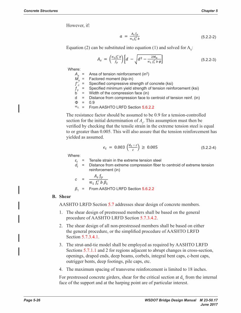
Concrete Structures Chapter 5
Page 5-26 WSDOT Bridge Design Manual M 23-50.17 June 2017
However,if:
5.2.2-1 table: 0.0948 �ƒ𝑐𝑐𝑐𝑐𝑐𝑐𝑐𝑐′ ≤ 0.2 (𝑘𝑘𝑘𝑘𝑘𝑘𝑘𝑘𝑘𝑘𝑘𝑘)
. 19�ƒ𝑐𝑐𝑐𝑐𝑐𝑐𝑐𝑐′ (𝑘𝑘𝑘𝑘𝑘𝑘𝑘𝑘𝑘𝑘𝑘𝑘)
0.65 ƒ𝑐𝑐𝑐𝑐𝑐𝑐𝑐𝑐′
0.0948 �ƒ𝑐𝑐𝑐𝑐′ (𝑘𝑘𝑘𝑘𝑘𝑘𝑘𝑘𝑘𝑘𝑘𝑘)
0.19�ƒ𝑐𝑐𝑐𝑐′ (𝑘𝑘𝑘𝑘𝑘𝑘𝑘𝑘𝑘𝑘𝑘𝑘)
0.24�ƒ𝑐𝑐𝑐𝑐′ (𝑘𝑘𝑘𝑘𝑘𝑘𝑘𝑘𝑘𝑘𝑘𝑘)
0.19�ƒ𝑐𝑐𝑐𝑐′ (𝑘𝑘𝑘𝑘𝑘𝑘𝑘𝑘𝑘𝑘𝑘𝑘)
0.65 ƒ𝑐𝑐𝑐𝑐′
0.0
0.45 ƒ𝑐𝑐𝑐𝑐′
0.60 ƒ𝑐𝑐𝑐𝑐′
0.40 ƒ𝑐𝑐𝑐𝑐′
5.2.2-1: 0.75 ≤ 𝜑𝜑𝜑𝜑 = 0.583 + 0.25 �𝑑𝑑𝑑𝑑𝑡𝑡𝑡𝑡𝑐𝑐𝑐𝑐− 1� ≤ 1.0
5.2.2-2: 0.75 ≤ 𝜑𝜑𝜑𝜑 = 0.650 + 0.15 �𝑑𝑑𝑑𝑑𝑡𝑡𝑡𝑡𝑐𝑐𝑐𝑐− 1� ≤ 0.9
5.2.2-3: 0.75 ≤ 𝜑𝜑𝜑𝜑 = 0.616 + 0.20 �𝑑𝑑𝑑𝑑𝑡𝑡𝑡𝑡𝑐𝑐𝑐𝑐− 1� ≤ 0.95
5.2.2-1: 𝑀𝑀𝑀𝑀𝑢𝑢𝑢𝑢 = 𝜙𝜙𝜙𝜙𝑀𝑀𝑀𝑀𝑛𝑛𝑛𝑛 = 𝜙𝜙𝜙𝜙𝐴𝐴𝐴𝐴𝑠𝑠𝑠𝑠ƒ𝑦𝑦𝑦𝑦 �𝑑𝑑𝑑𝑑 − 𝑎𝑎𝑎𝑎2�
5.2.2-2: 𝑎𝑎𝑎𝑎 = 𝐴𝐴𝐴𝐴𝑠𝑠𝑠𝑠 ƒ𝑦𝑦𝑦𝑦∝1𝑓𝑓𝑓𝑓𝑐𝑐𝑐𝑐′ 𝑏𝑏𝑏𝑏
5.2.2-3: 𝐴𝐴𝐴𝐴𝑠𝑠𝑠𝑠 = �∝1𝑓𝑓𝑓𝑓𝑐𝑐𝑐𝑐′ 𝑏𝑏𝑏𝑏
𝑓𝑓𝑓𝑓𝑦𝑦𝑦𝑦� �𝑑𝑑𝑑𝑑 −�𝑑𝑑𝑑𝑑2 − 2𝑀𝑀𝑀𝑀𝑢𝑢𝑢𝑢
∝1 𝑓𝑓𝑓𝑓𝑐𝑐𝑐𝑐′ 𝑏𝑏𝑏𝑏 𝜙𝜙𝜙𝜙�
5.2.2-4: 𝜖𝜖𝜖𝜖𝑡𝑡𝑡𝑡 = 0.003 �𝑑𝑑𝑑𝑑𝑡𝑡𝑡𝑡 − 𝑐𝑐𝑐𝑐𝑐𝑐𝑐𝑐� ≥ 0.005
𝑎𝑎𝑎𝑎 = 𝐴𝐴𝐴𝐴𝑠𝑠𝑠𝑠 ƒ𝑦𝑦𝑦𝑦
∝1 𝑓𝑓𝑓𝑓𝑐𝑐𝑐𝑐′ 𝑏𝑏𝑏𝑏 𝛽𝛽𝛽𝛽1
(5 .2 .2-2)
Equation(2)canbesubstitutedintoequation(1) and solved for As:
5.2.2-1 table: 0.0948 �ƒ𝑐𝑐𝑐𝑐𝑐𝑐𝑐𝑐′ ≤ 0.2 (𝑘𝑘𝑘𝑘𝑘𝑘𝑘𝑘𝑘𝑘𝑘𝑘)
. 19�ƒ𝑐𝑐𝑐𝑐𝑐𝑐𝑐𝑐′ (𝑘𝑘𝑘𝑘𝑘𝑘𝑘𝑘𝑘𝑘𝑘𝑘)
0.65 ƒ𝑐𝑐𝑐𝑐𝑐𝑐𝑐𝑐′
0.0948 �ƒ𝑐𝑐𝑐𝑐′ (𝑘𝑘𝑘𝑘𝑘𝑘𝑘𝑘𝑘𝑘𝑘𝑘)
0.19�ƒ𝑐𝑐𝑐𝑐′ (𝑘𝑘𝑘𝑘𝑘𝑘𝑘𝑘𝑘𝑘𝑘𝑘)
0.24�ƒ𝑐𝑐𝑐𝑐′ (𝑘𝑘𝑘𝑘𝑘𝑘𝑘𝑘𝑘𝑘𝑘𝑘)
0.19�ƒ𝑐𝑐𝑐𝑐′ (𝑘𝑘𝑘𝑘𝑘𝑘𝑘𝑘𝑘𝑘𝑘𝑘)
0.65 ƒ𝑐𝑐𝑐𝑐′
0.0
0.45 ƒ𝑐𝑐𝑐𝑐′
0.60 ƒ𝑐𝑐𝑐𝑐′
0.40 ƒ𝑐𝑐𝑐𝑐′
5.2.2-1: 0.75 ≤ 𝜑𝜑𝜑𝜑 = 0.583 + 0.25 �𝑑𝑑𝑑𝑑𝑡𝑡𝑡𝑡𝑐𝑐𝑐𝑐− 1� ≤ 1.0
5.2.2-2: 0.75 ≤ 𝜑𝜑𝜑𝜑 = 0.650 + 0.15 �𝑑𝑑𝑑𝑑𝑡𝑡𝑡𝑡𝑐𝑐𝑐𝑐− 1� ≤ 0.9
5.2.2-3: 0.75 ≤ 𝜑𝜑𝜑𝜑 = 0.616 + 0.20 �𝑑𝑑𝑑𝑑𝑡𝑡𝑡𝑡𝑐𝑐𝑐𝑐− 1� ≤ 0.95
5.2.2-1: 𝑀𝑀𝑀𝑀𝑢𝑢𝑢𝑢 = 𝜙𝜙𝜙𝜙𝑀𝑀𝑀𝑀𝑛𝑛𝑛𝑛 = 𝜙𝜙𝜙𝜙𝐴𝐴𝐴𝐴𝑠𝑠𝑠𝑠ƒ𝑦𝑦𝑦𝑦 �𝑑𝑑𝑑𝑑 − 𝑎𝑎𝑎𝑎2�
5.2.2-2: 𝑎𝑎𝑎𝑎 = 𝐴𝐴𝐴𝐴𝑠𝑠𝑠𝑠 ƒ𝑦𝑦𝑦𝑦∝1𝑓𝑓𝑓𝑓𝑐𝑐𝑐𝑐′ 𝑏𝑏𝑏𝑏
5.2.2-3: 𝐴𝐴𝐴𝐴𝑠𝑠𝑠𝑠 = �∝1𝑓𝑓𝑓𝑓𝑐𝑐𝑐𝑐′ 𝑏𝑏𝑏𝑏
𝑓𝑓𝑓𝑓𝑦𝑦𝑦𝑦� �𝑑𝑑𝑑𝑑 −�𝑑𝑑𝑑𝑑2 − 2𝑀𝑀𝑀𝑀𝑢𝑢𝑢𝑢
∝1 𝑓𝑓𝑓𝑓𝑐𝑐𝑐𝑐′ 𝑏𝑏𝑏𝑏 𝜙𝜙𝜙𝜙�
5.2.2-4: 𝜖𝜖𝜖𝜖𝑡𝑡𝑡𝑡 = 0.003 �𝑑𝑑𝑑𝑑𝑡𝑡𝑡𝑡 − 𝑐𝑐𝑐𝑐𝑐𝑐𝑐𝑐� ≥ 0.005
𝑎𝑎𝑎𝑎 = 𝐴𝐴𝐴𝐴𝑠𝑠𝑠𝑠 ƒ𝑦𝑦𝑦𝑦
∝1 𝑓𝑓𝑓𝑓𝑐𝑐𝑐𝑐′ 𝑏𝑏𝑏𝑏 𝛽𝛽𝛽𝛽1
(5 .2 .2-3)
Where: As = Area of tension reinforcement (in2) Mu = Factored moment (kip-in) ƒ′c = Specified compressive strength of concrete (ksi) ƒy = Specified minimum yield strength of tension reinforcement (ksi) b = Width of the compression face (in) d = Distance from compression face to centroid of tension reinf . (in) Φ = 0.9
5.2.2-1 table: 0.0948 �ƒ𝑐𝑐𝑐𝑐𝑐𝑐𝑐𝑐′ ≤ 0.2 (𝑘𝑘𝑘𝑘𝑘𝑘𝑘𝑘𝑘𝑘𝑘𝑘)
. 19�ƒ𝑐𝑐𝑐𝑐𝑐𝑐𝑐𝑐′ (𝑘𝑘𝑘𝑘𝑘𝑘𝑘𝑘𝑘𝑘𝑘𝑘)
0.65 ƒ𝑐𝑐𝑐𝑐𝑐𝑐𝑐𝑐′
0.0948 �ƒ𝑐𝑐𝑐𝑐′ (𝑘𝑘𝑘𝑘𝑘𝑘𝑘𝑘𝑘𝑘𝑘𝑘)
0.19�ƒ𝑐𝑐𝑐𝑐′ (𝑘𝑘𝑘𝑘𝑘𝑘𝑘𝑘𝑘𝑘𝑘𝑘)
0.24�ƒ𝑐𝑐𝑐𝑐′ (𝑘𝑘𝑘𝑘𝑘𝑘𝑘𝑘𝑘𝑘𝑘𝑘)
0.19�ƒ𝑐𝑐𝑐𝑐′ (𝑘𝑘𝑘𝑘𝑘𝑘𝑘𝑘𝑘𝑘𝑘𝑘)
0.65 ƒ𝑐𝑐𝑐𝑐′
0.0
0.45 ƒ𝑐𝑐𝑐𝑐′
0.60 ƒ𝑐𝑐𝑐𝑐′
0.40 ƒ𝑐𝑐𝑐𝑐′
5.2.2-1: 0.75 ≤ 𝜑𝜑𝜑𝜑 = 0.583 + 0.25 �𝑑𝑑𝑑𝑑𝑡𝑡𝑡𝑡𝑐𝑐𝑐𝑐− 1� ≤ 1.0
5.2.2-2: 0.75 ≤ 𝜑𝜑𝜑𝜑 = 0.650 + 0.15 �𝑑𝑑𝑑𝑑𝑡𝑡𝑡𝑡𝑐𝑐𝑐𝑐− 1� ≤ 0.9
5.2.2-3: 0.75 ≤ 𝜑𝜑𝜑𝜑 = 0.616 + 0.20 �𝑑𝑑𝑑𝑑𝑡𝑡𝑡𝑡𝑐𝑐𝑐𝑐− 1� ≤ 0.95
5.2.2-1: 𝑀𝑀𝑀𝑀𝑢𝑢𝑢𝑢 = 𝜙𝜙𝜙𝜙𝑀𝑀𝑀𝑀𝑛𝑛𝑛𝑛 = 𝜙𝜙𝜙𝜙𝐴𝐴𝐴𝐴𝑠𝑠𝑠𝑠ƒ𝑦𝑦𝑦𝑦 �𝑑𝑑𝑑𝑑 − 𝑎𝑎𝑎𝑎2�
5.2.2-2: 𝑎𝑎𝑎𝑎 = 𝐴𝐴𝐴𝐴𝑠𝑠𝑠𝑠 ƒ𝑦𝑦𝑦𝑦∝1𝑓𝑓𝑓𝑓𝑐𝑐𝑐𝑐′ 𝑏𝑏𝑏𝑏
5.2.2-3: 𝐴𝐴𝐴𝐴𝑠𝑠𝑠𝑠 = �∝1𝑓𝑓𝑓𝑓𝑐𝑐𝑐𝑐′ 𝑏𝑏𝑏𝑏
𝑓𝑓𝑓𝑓𝑦𝑦𝑦𝑦� �𝑑𝑑𝑑𝑑 −�𝑑𝑑𝑑𝑑2 − 2𝑀𝑀𝑀𝑀𝑢𝑢𝑢𝑢
∝1 𝑓𝑓𝑓𝑓𝑐𝑐𝑐𝑐′ 𝑏𝑏𝑏𝑏 𝜙𝜙𝜙𝜙�
5.2.2-4: 𝜖𝜖𝜖𝜖𝑡𝑡𝑡𝑡 = 0.003 �𝑑𝑑𝑑𝑑𝑡𝑡𝑡𝑡 − 𝑐𝑐𝑐𝑐𝑐𝑐𝑐𝑐� ≥ 0.005
𝑎𝑎𝑎𝑎 = 𝐴𝐴𝐴𝐴𝑠𝑠𝑠𝑠 ƒ𝑦𝑦𝑦𝑦
∝1 𝑓𝑓𝑓𝑓𝑐𝑐𝑐𝑐′ 𝑏𝑏𝑏𝑏 𝛽𝛽𝛽𝛽1
= From AASHTO LRFD Section 5 .6 .2 .2
Theresistancefactorshouldbeassumedtobe0.9foratension-controlledsection for the initial determination of As.Thisassumptionmustthenbeverifiedbycheckingthatthetensilestrainintheextremetensionsteelisequalto or greater than 0.005. This will also assure that the tension reinforcement has yielded as assumed.
5.2.2-1 table: 0.0948 �ƒ𝑐𝑐𝑐𝑐𝑐𝑐𝑐𝑐′ ≤ 0.2 (𝑘𝑘𝑘𝑘𝑘𝑘𝑘𝑘𝑘𝑘𝑘𝑘)
. 19�ƒ𝑐𝑐𝑐𝑐𝑐𝑐𝑐𝑐′ (𝑘𝑘𝑘𝑘𝑘𝑘𝑘𝑘𝑘𝑘𝑘𝑘)
0.65 ƒ𝑐𝑐𝑐𝑐𝑐𝑐𝑐𝑐′
0.0948 �ƒ𝑐𝑐𝑐𝑐′ (𝑘𝑘𝑘𝑘𝑘𝑘𝑘𝑘𝑘𝑘𝑘𝑘)
0.19�ƒ𝑐𝑐𝑐𝑐′ (𝑘𝑘𝑘𝑘𝑘𝑘𝑘𝑘𝑘𝑘𝑘𝑘)
0.24�ƒ𝑐𝑐𝑐𝑐′ (𝑘𝑘𝑘𝑘𝑘𝑘𝑘𝑘𝑘𝑘𝑘𝑘)
0.19�ƒ𝑐𝑐𝑐𝑐′ (𝑘𝑘𝑘𝑘𝑘𝑘𝑘𝑘𝑘𝑘𝑘𝑘)
0.65 ƒ𝑐𝑐𝑐𝑐′
0.0
0.45 ƒ𝑐𝑐𝑐𝑐′
0.60 ƒ𝑐𝑐𝑐𝑐′
0.40 ƒ𝑐𝑐𝑐𝑐′
5.2.2-1: 0.75 ≤ 𝜑𝜑𝜑𝜑 = 0.583 + 0.25 �𝑑𝑑𝑑𝑑𝑡𝑡𝑡𝑡𝑐𝑐𝑐𝑐− 1� ≤ 1.0
5.2.2-2: 0.75 ≤ 𝜑𝜑𝜑𝜑 = 0.650 + 0.15 �𝑑𝑑𝑑𝑑𝑡𝑡𝑡𝑡𝑐𝑐𝑐𝑐− 1� ≤ 0.9
5.2.2-3: 0.75 ≤ 𝜑𝜑𝜑𝜑 = 0.616 + 0.20 �𝑑𝑑𝑑𝑑𝑡𝑡𝑡𝑡𝑐𝑐𝑐𝑐− 1� ≤ 0.95
5.2.2-1: 𝑀𝑀𝑀𝑀𝑢𝑢𝑢𝑢 = 𝜙𝜙𝜙𝜙𝑀𝑀𝑀𝑀𝑛𝑛𝑛𝑛 = 𝜙𝜙𝜙𝜙𝐴𝐴𝐴𝐴𝑠𝑠𝑠𝑠ƒ𝑦𝑦𝑦𝑦 �𝑑𝑑𝑑𝑑 − 𝑎𝑎𝑎𝑎2�
5.2.2-2: 𝑎𝑎𝑎𝑎 = 𝐴𝐴𝐴𝐴𝑠𝑠𝑠𝑠 ƒ𝑦𝑦𝑦𝑦∝1𝑓𝑓𝑓𝑓𝑐𝑐𝑐𝑐′ 𝑏𝑏𝑏𝑏
5.2.2-3: 𝐴𝐴𝐴𝐴𝑠𝑠𝑠𝑠 = �∝1𝑓𝑓𝑓𝑓𝑐𝑐𝑐𝑐′ 𝑏𝑏𝑏𝑏
𝑓𝑓𝑓𝑓𝑦𝑦𝑦𝑦� �𝑑𝑑𝑑𝑑 −�𝑑𝑑𝑑𝑑2 − 2𝑀𝑀𝑀𝑀𝑢𝑢𝑢𝑢
∝1 𝑓𝑓𝑓𝑓𝑐𝑐𝑐𝑐′ 𝑏𝑏𝑏𝑏 𝜙𝜙𝜙𝜙�
5.2.2-4: 𝜖𝜖𝜖𝜖𝑡𝑡𝑡𝑡 = 0.003 �𝑑𝑑𝑑𝑑𝑡𝑡𝑡𝑡 − 𝑐𝑐𝑐𝑐𝑐𝑐𝑐𝑐� ≥ 0.005
𝑎𝑎𝑎𝑎 = 𝐴𝐴𝐴𝐴𝑠𝑠𝑠𝑠 ƒ𝑦𝑦𝑦𝑦
∝1 𝑓𝑓𝑓𝑓𝑐𝑐𝑐𝑐′ 𝑏𝑏𝑏𝑏 𝛽𝛽𝛽𝛽1
(5 .2 .2-4)
Where: εt = Tensile strain in the extreme tension steel dt = Distance from extreme compression fiber to centroid of extreme tension reinforcement (in) c =
5.2.2-1 table: 0.0948 �ƒ𝑐𝑐𝑐𝑐𝑐𝑐𝑐𝑐′ ≤ 0.2 (𝑘𝑘𝑘𝑘𝑘𝑘𝑘𝑘𝑘𝑘𝑘𝑘)
. 19�ƒ𝑐𝑐𝑐𝑐𝑐𝑐𝑐𝑐′ (𝑘𝑘𝑘𝑘𝑘𝑘𝑘𝑘𝑘𝑘𝑘𝑘)
0.65 ƒ𝑐𝑐𝑐𝑐𝑐𝑐𝑐𝑐′
0.0948 �ƒ𝑐𝑐𝑐𝑐′ (𝑘𝑘𝑘𝑘𝑘𝑘𝑘𝑘𝑘𝑘𝑘𝑘)
0.19�ƒ𝑐𝑐𝑐𝑐′ (𝑘𝑘𝑘𝑘𝑘𝑘𝑘𝑘𝑘𝑘𝑘𝑘)
0.24�ƒ𝑐𝑐𝑐𝑐′ (𝑘𝑘𝑘𝑘𝑘𝑘𝑘𝑘𝑘𝑘𝑘𝑘)
0.19�ƒ𝑐𝑐𝑐𝑐′ (𝑘𝑘𝑘𝑘𝑘𝑘𝑘𝑘𝑘𝑘𝑘𝑘)
0.65 ƒ𝑐𝑐𝑐𝑐′
0.0
0.45 ƒ𝑐𝑐𝑐𝑐′
0.60 ƒ𝑐𝑐𝑐𝑐′
0.40 ƒ𝑐𝑐𝑐𝑐′
5.2.2-1: 0.75 ≤ 𝜑𝜑𝜑𝜑 = 0.583 + 0.25 �𝑑𝑑𝑑𝑑𝑡𝑡𝑡𝑡𝑐𝑐𝑐𝑐− 1� ≤ 1.0
5.2.2-2: 0.75 ≤ 𝜑𝜑𝜑𝜑 = 0.650 + 0.15 �𝑑𝑑𝑑𝑑𝑡𝑡𝑡𝑡𝑐𝑐𝑐𝑐− 1� ≤ 0.9
5.2.2-3: 0.75 ≤ 𝜑𝜑𝜑𝜑 = 0.616 + 0.20 �𝑑𝑑𝑑𝑑𝑡𝑡𝑡𝑡𝑐𝑐𝑐𝑐− 1� ≤ 0.95
5.2.2-1: 𝑀𝑀𝑀𝑀𝑢𝑢𝑢𝑢 = 𝜙𝜙𝜙𝜙𝑀𝑀𝑀𝑀𝑛𝑛𝑛𝑛 = 𝜙𝜙𝜙𝜙𝐴𝐴𝐴𝐴𝑠𝑠𝑠𝑠ƒ𝑦𝑦𝑦𝑦 �𝑑𝑑𝑑𝑑 − 𝑎𝑎𝑎𝑎2�
5.2.2-2: 𝑎𝑎𝑎𝑎 = 𝐴𝐴𝐴𝐴𝑠𝑠𝑠𝑠 ƒ𝑦𝑦𝑦𝑦∝1𝑓𝑓𝑓𝑓𝑐𝑐𝑐𝑐′ 𝑏𝑏𝑏𝑏
5.2.2-3: 𝐴𝐴𝐴𝐴𝑠𝑠𝑠𝑠 = �∝1𝑓𝑓𝑓𝑓𝑐𝑐𝑐𝑐′ 𝑏𝑏𝑏𝑏
𝑓𝑓𝑓𝑓𝑦𝑦𝑦𝑦� �𝑑𝑑𝑑𝑑 −�𝑑𝑑𝑑𝑑2 − 2𝑀𝑀𝑀𝑀𝑢𝑢𝑢𝑢
∝1 𝑓𝑓𝑓𝑓𝑐𝑐𝑐𝑐′ 𝑏𝑏𝑏𝑏 𝜙𝜙𝜙𝜙�
5.2.2-4: 𝜖𝜖𝜖𝜖𝑡𝑡𝑡𝑡 = 0.003 �𝑑𝑑𝑑𝑑𝑡𝑡𝑡𝑡 − 𝑐𝑐𝑐𝑐𝑐𝑐𝑐𝑐� ≥ 0.005
𝑎𝑎𝑎𝑎 = 𝐴𝐴𝐴𝐴𝑠𝑠𝑠𝑠 ƒ𝑦𝑦𝑦𝑦
∝1 𝑓𝑓𝑓𝑓𝑐𝑐𝑐𝑐′ 𝑏𝑏𝑏𝑏 𝛽𝛽𝛽𝛽1
β1 = From AASHTO LRFD Section 5 .6 .2 .2
B. Shear
AASHTO LRFD Section 5.7addressessheardesignofconcretemembers.
1. Thesheardesignofprestressedmembersshallbebasedonthegeneralprocedure of AASHTO LRFD Section 5.7.3.4.2.
2. Thesheardesignofallnon-prestressedmembersshallbebasedoneitherthegeneralprocedure,orthesimplifiedprocedureofAASHTOLRFD Section 5.7.3.4.1.
3. Thestrut-and-tiemodelshallbeemployedasrequiredbyAASHTOLRFD Sections 5.7.1.1 and 2 forregionsadjacenttoabruptchangesincross-section,openings,drapedends,deepbeams,corbels,integralbentcaps,c-bentcaps,outriggerbents,deepfootings,pilecaps, etc.
4. The maximum spacing of transverse reinforcement is limited to 18 inches.
For prestressed concrete girders, shear for the critical section at dv from the internal face of the support and at the harping point are of particular interest.

Chapter 5 Concrete Structures
WSDOT Bridge Design Manual M 23-50.17 Page 5-27 June 2017
C. Interface Shear
Interfacesheartransfer(shearfriction)designistobeperformedinaccordancewith AASHTO LRFD Section 5.7.4.
If a roughened surface is required for shear transfer at construction joints in new construction,theyshallbeidentifiedintheplans.SeeStandard Specifications Section 6-02.3(12)A.
Whendesigningforsheartransferbetweennewandexistingconcrete,thedesignershall consider the high construction cost associated with roughening existing concrete surfaces. Whenever practical, the design for placing new concrete against existingconcreteshallbecompletedsuchthatrougheningoftheexistingconcretesurfaces is not required (i.e. use cohesion and friction factors for a surface that is not intentionally roughened).
Whentheadditionalcapacityprovidedbyaroughenedsurfaceisrequired,thesurfacerougheningshallmeettherequirementsspecifiedinAASHTO LRFD Section 5.7.4.4(i.e.uniform¼″ minimum amplitude). See Standard Specifications Section6-02.3(12)BandapplicableWSDOTspecialprovisionsforconcreteremoval for reference.
The spall pattern roughening detail shown in Figure 5.2.2-1maybeincludedonplansasanalternativetothedefaultuniform¼″ amplitude roughening.
¢ SPALL¢ SPALL
¢SPALL
¢SPALL3"
6"(TYP.)
3" À"
3"(T
YP.)
SURFACE SPALL4"ø MIN.
AREA BETWEEN SURFACE SPALLSSHALL BE ROUGHENED TO UNIFORMÀ" AMPLITUDE
SURFACE SPALL DEPTH½" MIN. TO ¾" MAX. (TYP.)
ORIGINAL CONCRETESURFACE PRIOR TOROUGHENING
SURFACE SPALL (TYP.)
ELEVATIONSECTION A
A
Spall Pattern Roughening DetailFigure 5.2.2-1
Concrete Structures Chapter 5
Page 5-28 WSDOT Bridge Design Manual M 23-50.17 June 2017
Interface shear in prestressed concrete girder design is critical at the interface connectionbetweendeckslabandgirder,andattheendconnectionofthegirderto a diaphragm orcrossbeam.Shearintheseareasisresistedbyroughened or saw-tooth shear keyed concrete as well as reinforcement extending from the girder.
1. Interface Shear Between Deck Slab and Girder
The top surfaces of prestressed concrete girders with cast-in-place decks shall beroughenedasdescribedinStandard Specifications Section 6-02.3(25)H. The interfaceshearisresistedbythegirderstirrupswhichextendupintothedeck slabas well as the roughenedtopsurfaceofthegirdertopflange.
It is conservative to compute the interface shear force using the full factored loadingappliedtothecompositedeckslabandgirder.However,theinterfaceshearforceneedonlybecomputedfromfactoredloadsappliedtothecompositesectionafterthedeckslabisplacedsuchassuperimposeddeadloadsand live loads.
ForStay-in-Place(SIP)decksystems,onlytheroughenedtopflangesurfacebetweenSIPpanelsupports(andtheportionofthepermanentnetcompressiveforce Pc on that section) is considered engaged in interface shear transfer.
2. Interface Shear Friction at Girder End
Aprestressedconcretegirdermayberequiredtocarryshearsattheendsurfaceof the girder.
An end condition atanintermediatepiercrossbeamis shown in Figure 5.2.2-2. TheshearwhichmustbecarriedalongtheinterfaceA-Aistheactualfactoredshear acting on the section. The portion of the girder end that is roughened with saw-toothed shear keysshownonthestandardgirderplansmaybeconsidered as a “surface intentionally roughened to an amplitude of 0.25 inches”. Shear resistancemustbedevelopedusinginterfacesheartheoryassumingthelongitudinalbarsandtheextendedstrandsareactivelyparticipating.Themainlongitudinal deckslabreinforcementisalreadyfullystressedbynegativebendingmomentsandthuscannotbeconsideredforshearrequirements.Allbars,includingtheextendedstrands,mustbeproperlyanchoredinordertobeconsideredeffective.Thisanchoragerequirementmustbeclearlyshownonthe plans.
Similarrequirementsexistforconnectingtheenddiaphragmatbridgeendswhere the diaphragm is cast on the girders (girder End Type A). In this case, however, loads consist only of the factored diaphragm dead load, approach slabdeadload,andthosewheelloadswhichcandistributetotheinterface.Longitudinalreinforcementprovidedatgirderendsshallbeidenticalinbothends of the girder for construction simplicity.
The program PGSuper does not check interface shear friction at girder ends. Standard girder plan details are adequate for girder End Types A and B. StandardgirderplandetailsshallbecheckedforadequacyforgirderEndTypesC and D.

Chapter 5 Concrete Structures
WSDOT Bridge Design Manual M 23-50.17 Page 5-29 June 2017
¢ PIER
PRESTRESSED GIRDER(WF SHOWN, OTHERSSIMILAR)
G4 BARS
G8 BARS
MAIN LONGITUDINAL BRIDGEDECK REINFORCING
G5 BARS
STRAND CHUCK AND ANCHORPLATE OR 2¾" x 1Â" STEELSTRAND ANCHOR
EXTENDEDSTRANDS
CAST IN PLACECONCRETE
End Connection for Continuous Span GirderFigure 5.2.2-2
D. Shear and Torsion
ThedesignforshearandtorsionisbasedonACI318-02Building Code4 Requirements for Structural Concrete and Commentary (318F-02) and is satisfactoryforbridgememberswithdimensionssimilartothosenormallyusedinbuildings.AASHTOLRFD Section 5.7.3.6mayalsobeusedfordesign.
According to Hsu5, utilizing ACI 318-02 is awkward and overly conservative when appliedtolarge-sizehollowmembers.CollinsandMitchell6 propose a rational designmethodforshearandtorsionbasedonthecompressionfieldtheoryorstrut-and-tiemethodforbothprestressedandnon-prestressedconcretebeams.Thesemethodsassumethatdiagonalcompressivestressescanbetransmittedthroughcracked concrete. Also, shear stresses are transmitted from one face of the crack to theotherbyacombinationofaggregateinterlockanddowelactionofthestirrups.
For recommendations and design examples, the designer can refer to the paper byM.P.CollinsandD.Mitchell,Shear and Torsion Design of Prestressed and Non-Prestressed Concrete Beams,PCIJournal,September-October1980,pp. 32-1006.
5.2.3 Strut-and-Tie ModelStrut-and-tiemodelsshallbeusednearregionsofdiscontinuityorwherebeamtheoryisnotapplicable. Design and detailing considerations for strut-and-tie modeling is covered in AASHTO LRFD Section 5.8.2. See Appendix 5-B for a strut-and-tie design example for a pier cap.

Concrete Structures Chapter 5
Page 5-30 WSDOT Bridge Design Manual M 23-50.17 June 2017
5.2.4 DeflectionandCamberA. General
Flexuralmembersaredesignedtohaveadequatestiffnesstolimitdeflectionsoranydeformationswhichmayadverselyaffectthestrengthorserviceabilityofthe structure at service load plus impact. The minimum superstructure depths are specifiedinAASHTOLRFDTable2.5.2.6.3-1anddeflectionsshallbecomputedinaccordance with AASHTO LRFD Section 5.6.3.2.6.
Accuratepredictionsofdeflectionsaredifficulttodetermine,sincemodulusofelasticity of concrete, Ec,varieswithstressandageofconcrete.Also,theeffectsofcreepondeflectionsaredifficulttoestimate.Forpracticalpurposes,anaccuracyof10to20percentisoftensufficient.Prestressingcanbeusedadvantageouslytocontroldeflections;however,therearecaseswhereexcessivecamberduetoprestresshascausedproblems.
B. Deflection Calculation for Prestressed Concrete Girders
The “D”dimensionisthecomputedgirderdeflectionatmidspan(positiveupward)immediatelypriortodeckslabplacement.
Standard Specifications Section 6-02.3(25)Kdefinestwolevelsofgirdercamberat the time the deck concrete is placed, denoted D @ 40 Days and D @ 120 Days. Theyshallbeshownintheplanstoprovidethecontractorwithlowerandupperboundsofcamberthatcanbeanticipatedinthefield.
PGSupercalculatesestimatedcambersat40days(D40) and 120 days (D120). Due tovariationsinobservedcamber,theseestimatedcambersaregenerallyconsideredtobeupperboundsattheirrespectivetimes.ThisisbasedonmeasuredgirdercambersofprestressedconcretegirderscomparedwiththeestimatedcambersfromPGSuper.
D @ 120 Daysistheupperboundofexpectedcamberrangeatagirderageof120days after the release of prestress and is primarily intended to mitigate interference betweenthetopofthecamberedgirderandtheplacementofconcretedeckreinforcement. It is also used to calculate the “A” dimension at the girder ends. The ageof120dayswaschosenbecausedatahasshownthatadditionalcambergrowthafterthisageisnegligible.D@120DaysmaybetakenasD120,theestimatedcamberat120daysreportedbyPGSuper.
D@40Daysisthelowerboundofexpectedcamberrangeatagirderageof40days(30daysaftertheearliestallowablegirdershippingageof10days).Tomatchtheprofilegrade,girderswithtoolittlecamberrequireanincreasedvolumeofhaunchconcretealongthegirderlength.Forgirderswithlargeflangewidths,suchastheWFseries,thiscanadduptosignificantquantitiesofadditionalconcreteforalargedeckplacement.Thus,thelowerboundofcamberallowsthecontractortoassess the risk of increased concrete quantities and mitigates claims for additional material.D@40Daysshallbetakenas50percentofD40,theestimatedcamberat40daysreportedbyPGSuper.
Figure5.2.4-1showsatypicalpatternofgirderdeflectionwithtimeatcenterlinespan.Portionsofthischaracteristiccurvearedescribedbelow.Thesubparagraphnumberscorrespondtocirclednumbersonthecurve.
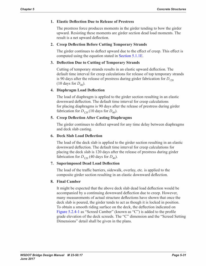
Chapter 5 Concrete Structures
WSDOT Bridge Design Manual M 23-50.17 Page 5-31 June 2017
1. Elastic Deflection Due to Release of Prestress
Theprestressforceproducesmomentsinthegirdertendingtobowthegirderupward. Resisting these moments are girder section dead load moments. The resultisanetupwarddeflection.
2. Creep Deflection Before Cutting Temporary Strands
Thegirdercontinuestodeflectupwardduetotheeffectofcreep.Thiseffectiscomputed using the equation stated in Section 5.1.1E.
3. Deflection Due to Cutting of Temporary Strands
Cuttingoftemporarystrandsresultsinanelasticupwarddeflection.The default time interval for creep calculations for release of top temporary strands is90daysafterthereleaseofprestressduringgirderfabricationforD120 (10 days for D40).
4. Diaphragm Load Deflection
The load of diaphragm is applied to the girder section resulting in an elastic downwarddeflection.The default time interval for creep calculations for placing diaphragms is 90 days after the release of prestress during girder fabricationforD120 (10 days for D40).
5. Creep Deflection After Casting Diaphragms
The girder continuestodeflectupwardforanytimedelaybetweendiaphragmsand deckslabcasting.
6. Deck Slab Load Deflection
The load of the deckslabisappliedtothegirdersectionresultinginanelasticdownwarddeflection.The default time interval for creep calculations for placingthedeckslabis120daysafterthereleaseofprestressduringgirderfabricationforD120 (40 days for D40).
7. Superimposed Dead Load Deflection
Theloadofthetrafficbarriers,sidewalk,overlay,etc.isappliedtothecompositegirdersectionresultinginanelasticdownwarddeflection.
8. Final Camber
Itmightbeexpectedthattheabovedeckslabdeadloaddeflectionwouldbeaccompaniedbyacontinuingdownwarddeflectionduetocreep.However, manymeasurementsofactualstructuredeflectionshaveshownthatoncethedeckslabispoured,thegirdertendstoactasthoughitislockedinposition.Toobtainasmoothridingsurfaceonthedeck,thedeflectionindicatedonFigure 5.2.4-1as“ScreedCamber”(known as “C”)isaddedtotheprofilegrade elevation of the deck screeds. The “C” dimension and the “Screed Setting Dimensions”detailshallbegivenintheplans.
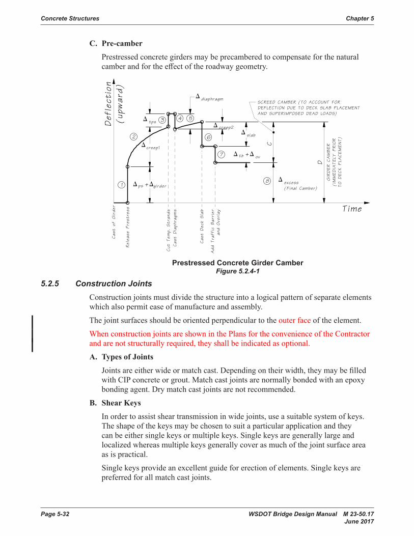
Concrete Structures Chapter 5
Page 5-32 WSDOT Bridge Design Manual M 23-50.17 June 2017
C. Pre-camber
Prestressedconcretegirdersmaybeprecamberedtocompensateforthenaturalcamberandfortheeffectoftheroadwaygeometry.
Def
lect
ion
(upw
ard)
Time
Cas
tof
Girde
r
Relea
sePre
stre
ss
Cas
tDiaph
ragm
s
Cas
tDec
kSlab
Add
Tra
ffic
Bar
rier
and
Ove
rlay
Cut
Tem
p.Str
ands
ùcreep1
ù +ùgirderps
ùdiaphragm
ùcreep2
C
ùtps
ùexcess(Final Camber)
ù +ùovtb
ùslab
GIRDER
CAMBER
(IMMEDIA
TELY
PRIOR
TO
DECK
PLA
CEMENT)
D
1
2
3 4 5
6
7
8
SCREED CAMBER (TO ACCOUNT FORDEFLECTION DUE TO DECK SLAB PLACEMENTAND SUPERIMPOSED DEAD LOADS)
Prestressed Concrete Girder CamberFigure 5.2.4-1
5.2.5 Construction JointsConstruction joints must divide the structure into a logical pattern of separate elements whichalsopermiteaseofmanufactureandassembly.
Thejointsurfacesshouldbeorientedperpendiculartotheouter face of the element.
When construction joints are shown in the Plans for the convenience of the Contractor andarenotstructurallyrequired,theyshallbeindicatedasoptional.
A. Types of Joints
Jointsareeitherwideormatchcast.Dependingontheirwidth,theymaybefilledwith CIPconcreteorgrout.Matchcastjointsarenormallybondedwithanepoxybondingagent.Drymatchcastjointsarenotrecommended.
B. Shear Keys
Inordertoassistsheartransmissioninwidejoints,useasuitablesystemofkeys.Theshapeofthekeysmaybechosentosuitaparticularapplicationandtheycanbeeithersinglekeysormultiplekeys.Singlekeysaregenerallylargeandlocalized whereas multiple keys generally cover as much of the joint surface area as is practical.
Single keys provide an excellent guide for erection of elements. Single keys are preferred for all match cast joints.

Chapter 5 Concrete Structures
WSDOT Bridge Design Manual M 23-50.17 Page 5-33 June 2017
Foralltypesofjoints,thesurfacesmustbeclean,freefromgreaseandoil,etc.Whenusingepoxyforbonding,thejointsshallbelightlysandblastedtoremovelaitance. For CIP or other types of wide joints, the adjacent concrete surfaces shall beroughenedandkeptthoroughlywet,priortoconstructionofthejoint.CIP joints are generally preferred.
5.2.6 Inspection Lighting and AccessA. Confined Spaces
See Section 10.8.1fordesignrequirementsforconfinedspaces.
B. Access Hatch, Air Vent Holes and Inspection Lighting
Box girders with inside clear height of less than or equal to 4 feet do not require access, lighting, receptacles and ventilation. Utilities, longitudinal restrainers and other components requiring inspection or maintenance are not permitted inside the boxgirdercells.
Boxgirderswithinsideclearheightgreaterthan4feetbutlessthan6.5feetshallhaveaccess,lighting,receptaclesandventilationprovidedinsideeachboxgirdercell containing utilities, longitudinal restrainers and other components requiring inspection or maintenance.
Box girders with inside clear height greater than or equal to 6.5 feet shall have access, lighting, receptacles and ventilation provided inside.
Access,lighting,receptaclesandventilationshallnotbeprovidedinsideprestressedconcretetubgirdercells.Utilities,longitudinalrestrainersandothercomponents requiring inspection or maintenance are not permitted inside the girder cells.
Accessdoorsshallhaveaminimum2′-6″diameteror2′-6″squareclearopening.Lockboxlatchesshallbeinstalledonallaccessdoorsaccessiblefromgroundlevel.Accesshatchesshallswingintotheboxgirdersandshallbeplacedatlocationsthatdonotimpacttraffic.Lightingandreceptaclerequirementsshall conform to Design Manual Chapter 1040. Air vents shall conform to Figures 5.2.6-1 and 5.2.6-2.
Box girder penetrations greater than one inch in diameter through the exterior shall becoveredwithgalvanizedwiremeshscreentopreventverminandbirdsfromaccessingthepenetrationandtheinterioroftheboxgirder.Thewiresshallhaveamaximumspacingof1inchinbothdirections.
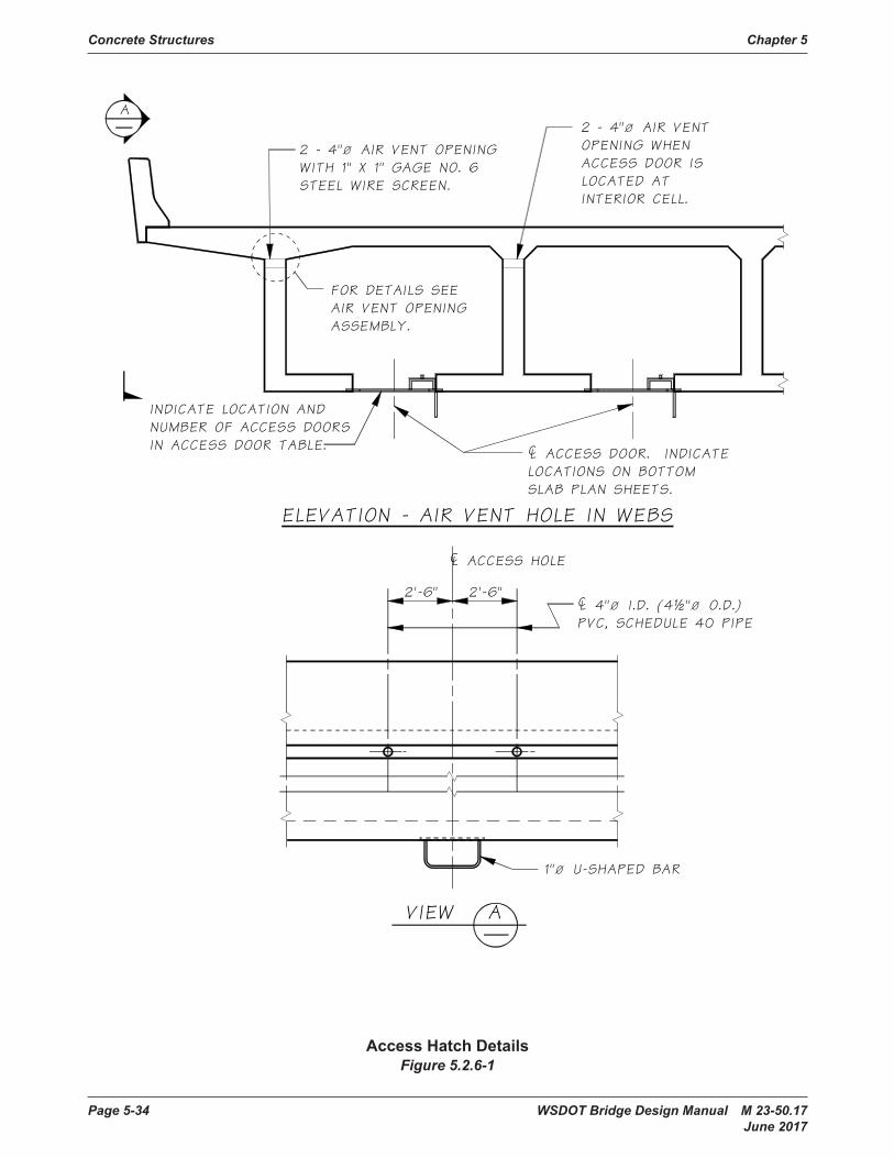
Concrete Structures Chapter 5
Page 5-34 WSDOT Bridge Design Manual M 23-50.17 June 2017
Access Hatch DetailsFigure 5.2.6-1

Chapter 5 Concrete Structures
WSDOT Bridge Design Manual M 23-50.17 Page 5-35 June 2017
Air Vent Opening DetailFigure 5.2.6-2

Page 5-36 WSDOT Bridge Design Manual M 23-50.17 June 2017
Concrete Structures Chapter 5
5.3 Reinforced Concrete Box Girder BridgesPost-tensioningshallberequiredforallnewCIPreinforcedconcretesingle-spanormulti-spanboxgirderbridges.
TheuseofCIPreinforcedconcrete(RC)boxgirderbridgeswithoutpost-tensioningshallberestrictedtowideningexistingRCboxgirderbridges.RCboxgirderbridgesmayalsobeusedforbridgeswithtightcurvaturesorirregulargeometryupontheWSDOTBridgeDesignEngineer’sapproval.PartialprestressingshallnotbeconsideredfordesignofRCboxgirders.
TheperformanceandlongevityofRCboxgirderbridgeshavebeenamajorconcern.CrackinginRCboxgirdersareflexuralinnatureandareaninherentpartofreinforcedconcretedesign.RCboxgirdersaredesignedforultimatestrengthandcheckedfordistributionofreinforcementforserviceconditionsandcontrolofcracking.Thismeansthattheconcretecracksunderappliedloadsbutthecracksareundercontrol.OpencracksinRCboxgirdersresultinrebarcorrosionandconcretedeterioration,affectingthebridgelongevity.Post-tensioningRCboxgirderseliminatescracks,limitscorrosion, and improves structural performance.
TheaboverequirementsapplyequallytoRCT-beamandslabbridges.However,thesetypes of superstructures are not encouraged. See also Sections 2.4.1.C and 2.4.1.D.
5.3.1 Box Girder Basic GeometriesA. Web Spacing
Themosteconomicalwebspacingforordinaryboxgirderbridgesvariesfromabout8to12feet.Greatergirderspacingrequiressomeincreaseinbothtopandbottomslabthickness,butthecostoftheadditionalconcretecanbeoffsetbydecreasingthetotalnumberofgirderstems.Fewergirderstemsreducestheamountof form work required and can lower costs.
Thenumberofgirderstemscanbereducedbycantileveringthetopslabbeyondthe exterior girders. A deck overhang of approximately one-half the girder spacing generally gives satisfactory results. This procedure usually results in a more aestheticaswellasamoreeconomicalbridge.
For girder stem spacing in excess of 12 feet or cantilever overhang in excess of6feet,transversepost-tensioningshallbeused.
B. Basic Dimensions
Thebasicdimensionsforconcreteboxgirderswithverticaland sloped exterior webs are shown in Figures 5.3.1-1 and 5.3.1-2, respectively.
1. Top Slab Thickness, T1 (includes ½″ wearing surface)
5.3.1‐B1 �� � ���� � �����
5.3.1‐B2 �� � �� ������
5.3.2‐1 ��� � �� ��
��
5.3.2‐2 ��� � ������� � ���
5.3.3‐1 ��� � ������
5.3.3‐2 �� � �������
5.3.3‐3 ��� � �����������
5.3.3.4 �� � ������ � ����������
5.3.3‐5 �� � ������������ �� � ��� � ���������
������ �
butnotlessthan7″ with overlay or 7.5″ without overlay.

WSDOT Bridge Design Manual M 23-50.17 Page 5-37 June 2017
Chapter 5 Concrete Structures
2. Bottom Slab Thickness, T2
i. Near center span
5.3.1‐B1 �� � ���� � �����
5.3.1‐B2 �� � �� ������
5.3.2‐1 ��� � �� ��
��
5.3.2‐2 ��� � ������� � ���
5.3.3‐1 ��� � ������
5.3.3‐2 �� � �������
5.3.3‐3 ��� � �����������
5.3.3.4 �� � ������ � ����������
5.3.3‐5 �� � ������������ �� � ��� � ���������
������ �
butnotlessthan5.5″ (normally 6.0″ is used).
ii. Near intermediate piers
Thickeningofthebottomslabisoftenusedinnegativemomentregionstocontrolcompressivestressesthataresignificant.
Transitionslope=24:1(seeT2inFigure 5.3.1-1).
3. Girder Stem (Web) Thickness, T3
i. Near Center Span
Minimum T3 = 9.0″ — vertical
Minimum T3 = 10.0″ — sloped
ii. Near Supports
Thickening of girder stems is used in areas adjacent to supports to control shear requirements.
Changesingirderwebthicknessshallbetaperedforaminimumdistanceof12timesthedifferenceinwebthickness.
Maximum T3 = T3 + 4.0″ maximum
Transitionlength=12×(differenceinwebthickness)
4. Intermediate Diaphragm Thickness, T4 and Diaphragm Spacing
i. FortangentandcurvedbridgewithR>800feet
T4 = 0″ (diaphragms are not required.)
ii. ForcurvedbridgewithR<800feet
T4 = 8.0″
Diaphragmspacingshallbeasfollows:
For600′<R<800′at½pt.ofspan.
For 400′<R<600′at⅓pt.ofspan.
ForR<400′at¼pt.ofspan.
C. Construction Considerations Reviewthefollowingconstructionconsiderationstominimizeconstructability
problems:1. Constructionjointsatslab/steminterfaceorfillet/steminterfaceattopslabare
appropriate.2. All construction joints to have roughened surfaces.3. Bottomslabisparalleltotopslab(constantdepth).4. Girder stems are vertical.

Page 5-38 WSDOT Bridge Design Manual M 23-50.17 June 2017
Concrete Structures Chapter 5
5. Deadloaddeflectionandcambertonearest⅛″.6. Skewandcurvatureeffectshavebeenconsidered.7. Thermaleffectshavebeenconsidered.8. Thepotentialforfalseworksettlementisacceptable.Thisalwaysrequires
addedstirrupreinforcementinslopedouterwebs.
D. Load Distribution
1. Unit Design
AccordingtotheAASHTOLRFD,theentireslabwidthshallbeassumedeffectiveforcompression.Itisbotheconomicalanddesirabletodesignthe entire superstructure as a unit rather than as individual girders. When a reinforcedboxgirderbridgeisdesignedasanindividualgirderwithadeckoverhang, the positive reinforcement is congested in the exterior cells. The unitdesignmethodpermitsdistributingallgirderreinforcementuniformlythroughout the width of the structure.
2. Dead Loads
Include additional D.L. fortopdeckforms:
5 pounds per square foot of the area.
10poundspersquarefootifwebspacing>10′-0″.
3. Live Load
See Section 3.9.4forliveloaddistributiontosuperstructureandsubstructure.

WSDOT Bridge Design Manual M 23-50.17 Page 5-39 June 2017
Chapter 5 Concrete Structures
Basic Dimensions–Vertical WebsFigure 5.3.1-1

Page 5-40 WSDOT Bridge Design Manual M 23-50.17 June 2017
Concrete Structures Chapter 5
Basic Dimensions–Sloped WebsFigure 5.3.1-2
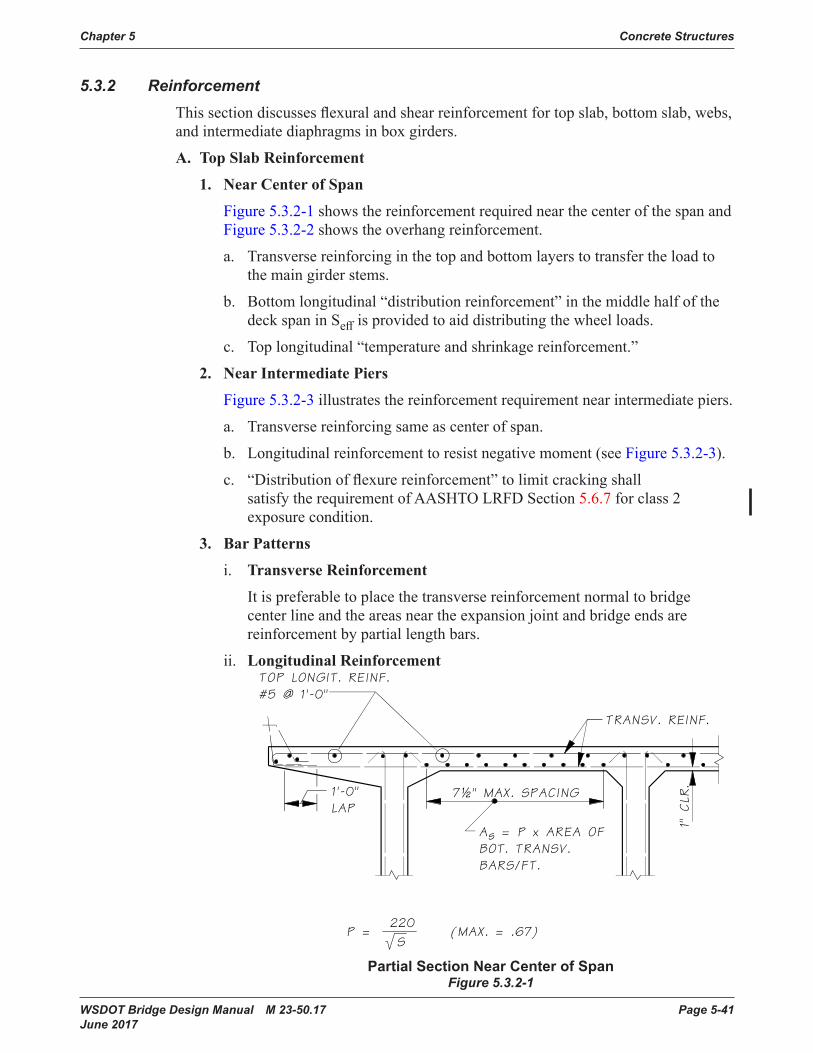
WSDOT Bridge Design Manual M 23-50.17 Page 5-41 June 2017
Chapter 5 Concrete Structures
5.3.2 ReinforcementThissectiondiscussesflexuralandshearreinforcementfortopslab,bottomslab,webs,andintermediatediaphragmsinboxgirders.
A. Top Slab Reinforcement
1. Near Center of Span
Figure 5.3.2-1 shows the reinforcement required near the center of the span and Figure 5.3.2-2 shows the overhang reinforcement.
a. Transversereinforcinginthetopandbottomlayerstotransfertheloadtothe main girder stems.
b. Bottomlongitudinal“distributionreinforcement”inthemiddlehalfofthedeck span in Seffisprovidedtoaiddistributingthewheelloads.
c. Top longitudinal “temperature and shrinkage reinforcement.”
2. Near Intermediate Piers
Figure 5.3.2-3 illustrates the reinforcement requirement near intermediate piers.
a. Transverse reinforcing same as center of span.
b. Longitudinalreinforcementtoresistnegativemoment(seeFigure 5.3.2-3).
c. “Distributionofflexurereinforcement”tolimitcrackingshallsatisfy the requirement of AASHTO LRFD Section 5.6.7 for class 2 exposure condition.
3. Bar Patterns
i. Transverse Reinforcement
Itispreferabletoplacethetransversereinforcementnormaltobridgecenterlineandtheareasneartheexpansionjointandbridgeendsarereinforcementbypartiallengthbars.
ii. Longitudinal Reinforcement
Partial Section Near Center of SpanFigure 5.3.2-1

Page 5-42 WSDOT Bridge Design Manual M 23-50.17 June 2017
Concrete Structures Chapter 5
Overhang DetailFigure 5.3.2-2
Top Slab Flexural Reinforcing Near Intermediate Pier Figure 5.3.2-3
Partial Plans at AbutmentsFigure 5.3.2-4
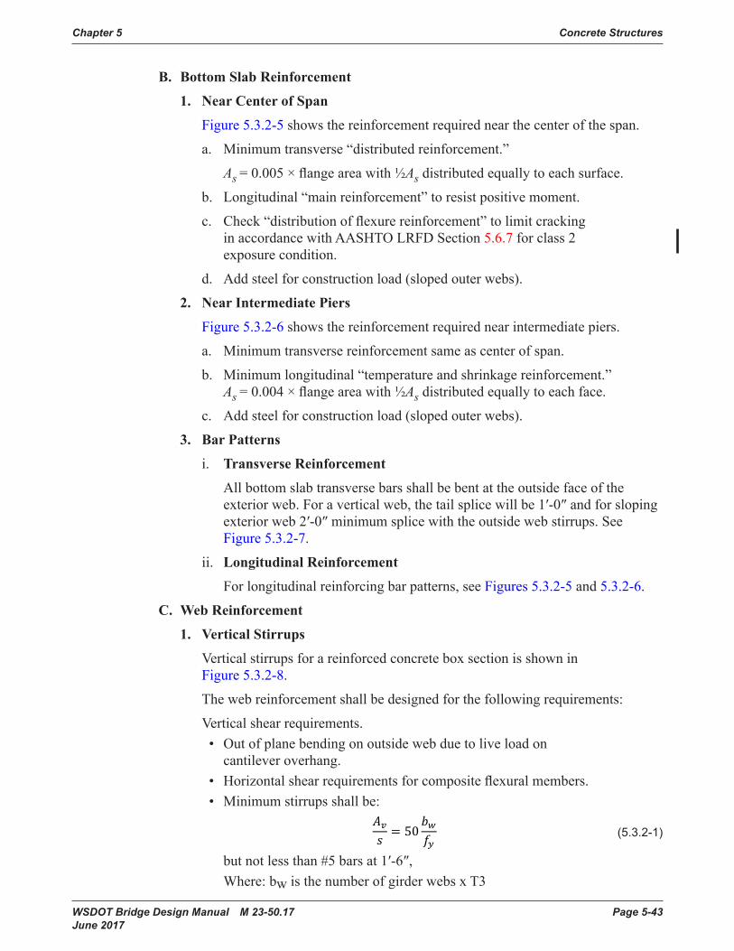
WSDOT Bridge Design Manual M 23-50.17 Page 5-43 June 2017
Chapter 5 Concrete Structures
B. Bottom Slab Reinforcement
1. Near Center of Span
Figure 5.3.2-5 shows the reinforcement required near the center of the span.
a. Minimumtransverse“distributedreinforcement.”
As =0.005×flangeareawith½Asdistributedequallytoeachsurface.
b. Longitudinal“mainreinforcement”toresistpositivemoment.
c. Check“distributionofflexurereinforcement”tolimitcrackingin accordance with AASHTO LRFD Section 5.6.7 for class 2 exposure condition.
d. Addsteelforconstructionload(slopedouterwebs).
2. Near Intermediate Piers
Figure 5.3.2-6 shows the reinforcement required near intermediate piers.
a. Minimum transverse reinforcement same as center of span.
b. Minimumlongitudinal“temperatureandshrinkagereinforcement.” As =0.004×flangeareawith½Asdistributedequallytoeachface.
c. Addsteelforconstructionload(slopedouterwebs).
3. Bar Patterns
i. Transverse Reinforcement
Allbottomslabtransversebarsshallbebentattheoutsidefaceoftheexteriorweb.Foraverticalweb,thetailsplicewillbe1′-0″andforslopingexteriorweb2′-0″minimumsplicewiththeoutsidewebstirrups.SeeFigure 5.3.2-7.
ii. Longitudinal Reinforcement
Forlongitudinalreinforcingbarpatterns,seeFigures 5.3.2-5 and 5.3.2-6.
C. Web Reinforcement
1. Vertical Stirrups
VerticalstirrupsforareinforcedconcreteboxsectionisshowninFigure 5.3.2-8.
Thewebreinforcementshallbedesignedforthefollowingrequirements:
Vertical shear requirements.• Outofplanebendingonoutsidewebduetoliveloadon
cantilever overhang.• Horizontalshearrequirementsforcompositeflexuralmembers.• Minimumstirrupsshallbe:
(5 .3 .2-1)
butnotlessthan#5barsat1′-6″, Where:bwisthenumberofgirderwebsxT3
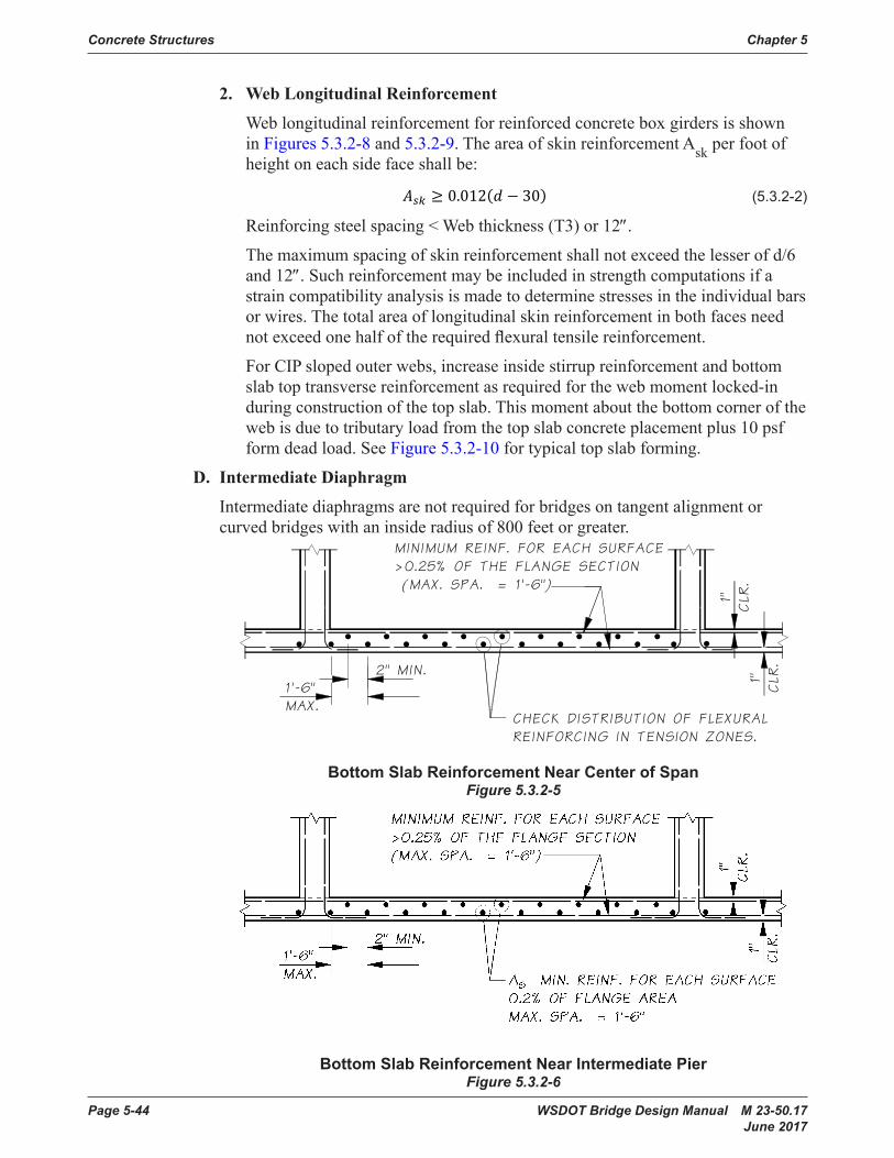
Page 5-44 WSDOT Bridge Design Manual M 23-50.17 June 2017
Concrete Structures Chapter 5
2. Web Longitudinal Reinforcement
Weblongitudinalreinforcementforreinforcedconcreteboxgirdersisshownin Figures 5.3.2-8 and 5.3.2-9. The area of skin reinforcement Ask per foot of heightoneachsidefaceshallbe:
(5 .3 .2-2)
Reinforcingsteelspacing<Webthickness(T3)or12″.
The maximum spacing of skin reinforcement shall not exceed the lesser of d/6 and 12″.Suchreinforcementmaybeincludedinstrengthcomputationsifastraincompatibilityanalysisismadetodeterminestressesintheindividualbarsorwires.Thetotalareaoflongitudinalskinreinforcementinbothfacesneednotexceedonehalfoftherequiredflexuraltensilereinforcement.
For CIPslopedouterwebs,increaseinsidestirrupreinforcementandbottomslabtoptransversereinforcementasrequiredforthewebmomentlocked-induringconstructionofthetopslab.Thismomentaboutthebottomcornerofthewebisduetotributaryloadfromthetopslabconcreteplacementplus10psfform dead load. See Figure 5.3.2-10fortypicaltopslabforming.
D. Intermediate Diaphragm
Intermediatediaphragmsarenotrequiredforbridgesontangentalignmentorcurvedbridgeswithaninsideradiusof800feetorgreater.
Bottom Slab Reinforcement Near Center of SpanFigure 5.3.2-5
Bottom Slab Reinforcement Near Intermediate PierFigure 5.3.2-6
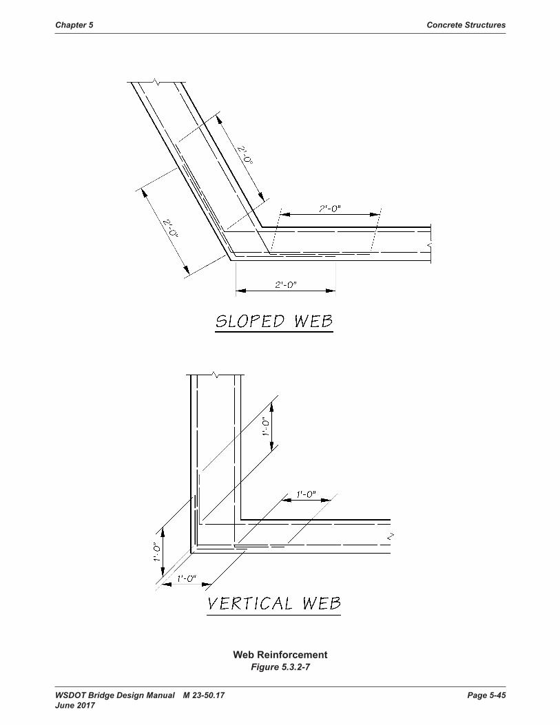
WSDOT Bridge Design Manual M 23-50.17 Page 5-45 June 2017
Chapter 5 Concrete Structures
Web ReinforcementFigure 5.3.2-7

Page 5-46 WSDOT Bridge Design Manual M 23-50.17 June 2017
Concrete Structures Chapter 5
Web Reinforcement DetailsFigure 5.3.2-8

WSDOT Bridge Design Manual M 23-50.17 Page 5-47 June 2017
Chapter 5 Concrete Structures
Web Reinforcement Details Figure 5.3.2-9

Page 5-48 WSDOT Bridge Design Manual M 23-50.17 June 2017
Concrete Structures Chapter 5
Notes:1. The diagonal brace supports web forms during web pour. After cure, the web is stiffer than the brace,
and the web attracts load from subsequent concrete placements.2. The tributary load includes half the overhang because the outer web form remains tied to and transfers
load to the web which is considerably stiffer than the formwork.3. Increase web reinforcement for locked-in construction load due to top slab forming for sloped web
box girders.
Typical Top Slab Forming for Sloped Web Box Girder Figure 5.3.2-10
WSDOT Bridge Design Manual M 23-50.17 Page 5-49 June 2017
Chapter 5 Concrete Structures
5.3.3 CrossbeamA. General Crossbeamshallbedesignedinaccordancewiththerequirementsofstrengthlimit
statedesignofAASHTOLRFDandshallsatisfytheserviceabilityrequirementsforcrack control.
B. Basic Geometry Foraestheticpurposes,itispreferabletokeepthecrossbeamwithinthe
superstructuresothatthebottomslaboftheentirebridgeisacontinuousplanesurfaceinterruptedonlybythecolumns.Althoughthedepthofthecrossbeammaybelimited,thewidthcanbemadeaswideasnecessarytosatisfydesignrequirements.Normally,itvariesfrom3feettothedepthofboxbutisnotlessthanthecolumnsizeplus1′-0″toallowplacementofthecolumnreinforcementasshown in see Figures 5.3.3-1 and 5.3.3-2.
CrossbeamsonboxgirdertypeofconstructionshallbedesignedasaTbeamutilizingtheflangeincompression,assumingthedeckslabactsasaflangeforpositivemomentandbottomslabaflangefornegativemoment.Theeffectiveoverhangoftheflangeonacantileverbeamshallbelimitedtosixtimestheflangethickness.
Thebottomslabthicknessisfrequentlyincreasednearthecrossbeaminordertokeepthemainboxgirdercompressivestressestoadesirablelevelfornegativegirder moments as shown in Figures 5.3.3-1 and 5.3.3-2.Thisbottomslabflarealsohelpsresistnegativecrossbeammoments.Considerationshouldbegiventoflaringthebottomslabatthecrossbeamfordesigningthecapevenifitisnotrequiredforresisting main girder moments.
C. Loads Forconcreteboxgirdersthesuperstructuredeadloadshallbeconsideredas
uniformlydistributedoverthecrossbeam.Forconcreteboxgirderstheliveloadshallbeconsideredasthetruckloaddirectlytothecrossbeamfromthewheelaxles.Truckaxlesshallbemovedtransverselyoverthecrossbeamtoobtainthemaximumdesignforcesforthecrossbeamandsupportingcolumns.
D. Reinforcement Design and Details Thecrossbeamsectionconsistsofrectangularsectionwithoverhangingdeckand
bottomslabifapplicable.Theeffectivewidthofthecrossbeamflangeoverhangshallbetakenasthelesserof:• 6timesslabthickness,• 1/10 of column spacing, or• 1/20ofcrossbeamcantileverasshowninFigure 5.3.3-3.
Thecrossbeamshallhaveaminimumwidthofcolumndimensionplus6″. Crossbeamisusuallycasttothefilletbelowthetopslab.Toavoidcrackingof
concreteontopofthecrossbeam,constructionreinforcementshallbeprovidedatapproximately3″belowtheconstructionjoint.Thedesignmomentforconstructionreinforcementshallbethefactorednegativedeadloadmomentduetotheweightofcrossbeamandadjacent10′ofsuperstructureeachside.Thetotalamountofconstructionreinforcementshallbeadequatetodevelopanultimatemomentatthecritical section at least 1.2 times the cracking moment Mcr.

Page 5-50 WSDOT Bridge Design Manual M 23-50.17 June 2017
Concrete Structures Chapter 5
Crossbeam Top Reinforcement for Skew Angle ≤ 25° Figure 5.3.3-1
Crossbeam Top Reinforcement for Skew Angle > 25°Figure 5.3.3-2

WSDOT Bridge Design Manual M 23-50.17 Page 5-51 June 2017
Chapter 5 Concrete Structures
slab6xt or1/10 x col.spacing
total width
6" min.slab6xt or
1/10 x col.spacing
6xt or1/10 x col.spacing
slab
tto
pslab
bot.
slab
t
Effective Width of Crossbeam Figure 5.3.3-3

Page 5-52 WSDOT Bridge Design Manual M 23-50.17 June 2017
Concrete Structures Chapter 5
Specialattentionshouldbegiventothedetailstoensurethatthecolumnandcrossbeamreinforcementwillnotinterferewitheachother.Thiscanbeaproblemespeciallywhenroundcolumnswithagreatnumberofverticalbarsmustbemeshedwithaconsiderableamountofpositivecrossbeamreinforcementpassingover the columns.
1. Top Reinforcement
The negative moment criticalsectionshallbeatthe¼pointofthesquareorequivalent square columns.
i. When Skew Angle ≤ 25°
Ifthebridgeistangentorslightlyskeweddecktransversereinforcementisnormalorradialtocenterlinebridge,thenegativecapreinforcementcanbeplacedeitherincontactwithtopdecknegativereinforcement(see Figure 5.3.3-1) or directly under the main deck reinforcement.
ii. When Skew Angle > 25°
When the structure is on a greater skew and the deck steel is normal orradialtothelongitudinalcenterlineofthebridge,thenegativecapreinforcementshouldbeloweredtobelowthemaindeckreinforcement(see Figure 5.3.3-2).
iii. To avoid cracking of concrete
Interim reinforcement isrequiredbelowtheconstructionjointincrossbeams.
2. Skin Reinforcement
Longitudinalskinreinforcementshallbeprovidedinaccordancewith AASHTO LRFD Section 5.6.7.
5.3.4 End DiaphragmA. Basic Geometry
Bearings at the end diaphragms are usually located under the girder stems to transfer loads directly to the pier as shown in Figure 5.3.4-1. In this case, the diaphragm width shallbeequaltoorgreaterthanbearinggroutpadsasshownFigure 5.3.4-2.
Designer shallprovideaccessspaceformaintenanceandinspectionofbearings.
Allowance shallbeprovidedtoremoveandreplacethebearings.Liftpointlocations,jackcapacity,numberofjacks,andmaximumpermittedliftshallbeshown in the plan details.
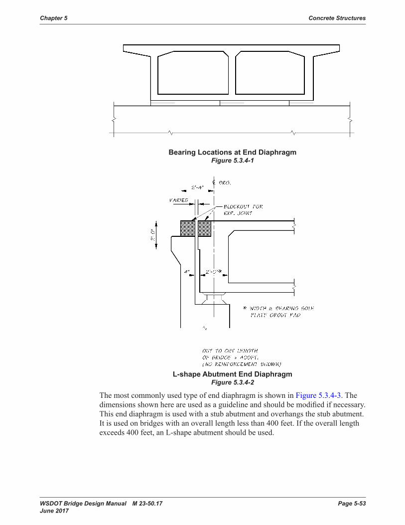
WSDOT Bridge Design Manual M 23-50.17 Page 5-53 June 2017
Chapter 5 Concrete Structures
Bearing Locations at End Diaphragm Figure 5.3.4-1
L-shape Abutment End Diaphragm Figure 5.3.4-2
The most commonly used type of end diaphragm is shown in Figure 5.3.4-3. The dimensionsshownhereareusedasaguidelineandshouldbemodifiedifnecessary.Thisenddiaphragmisusedwithastubabutmentandoverhangsthestubabutment.Itisusedonbridgeswithanoveralllengthlessthan400feet.Iftheoveralllengthexceeds400feet,anL-shapeabutmentshouldbeused.

Page 5-54 WSDOT Bridge Design Manual M 23-50.17 June 2017
Concrete Structures Chapter 5
End Diaphragm with Stub AbutmentFigure 5.3.4-3
B. Reinforcing Steel Details
Typical reinforcement details for an end diaphragm are shown in Figure 5.3.4-4.
Typical End Diaphragm ReinforcementFigure 5.3.4-4
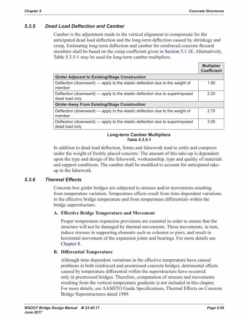
WSDOT Bridge Design Manual M 23-50.17 Page 5-55 June 2017
Chapter 5 Concrete Structures
5.3.5 DeadLoadDeflectionandCamberCamberistheadjustmentmadetotheverticalalignmenttocompensatefortheanticipateddeadloaddeflectionandthelong-termdeflectioncausedbyshrinkageandcreep.Estimatinglong-termdeflectionandcamberforreinforcedconcreteflexuralmembersshallbebasedonthecreepcoefficientgiveninSection 5.1.1E. Alternatively, Table5.3.5-1 maybeusedforlong-termcambermultipliers.
Multiplier Coefficient
Girder Adjacent to Existing/Stage ConstructionDeflection (downward) — apply to the elastic deflection due to the weight of member
1 .90
Deflection (downward) — apply to the elastic deflection due to superimposed dead load only
2 .20
Girder Away From Existing/Stage ConstructionDeflection (downward) — apply to the elastic deflection due to the weight of member
2 .70
Deflection (downward) — apply to the elastic deflection due to superimposed dead load only
3 .00
Long-term Camber MultipliersTable 5.3.5-1
Inadditiontodeadloaddeflection,formsandfalseworktendtosettleandcompressunder the weight of freshly placed concrete. The amount of this take-up is dependent upon the type and design of the falsework, workmanship, type and quality of materials andsupportconditions.Thecambershallbemodifiedtoaccountforanticipatedtake-up in the falsework.
5.3.6 ThermalEffectsConcreteboxgirderbridgesaresubjectedtostressesand/ormovementsresultingfromtemperaturevariation.Temperatureeffectsresultfromtime-dependentvariationsintheeffectivebridgetemperatureandfromtemperaturedifferentialswithinthebridgesuperstructure.
A. Effective Bridge Temperature and Movement
Proper temperature expansion provisions are essential in order to ensure that the structurewillnotbedamagedbythermalmovements.Thesemovements,inturn,induce stresses in supporting elements such as columns or piers, and result in horizontalmovementoftheexpansionjointsandbearings.FormoredetailsseeChapter 8.
B. Differential Temperature
Althoughtime-dependentvariationsintheeffectivetemperaturehavecausedproblemsinbothreinforcedandprestressedconcretebridges,detrimentaleffectscausedbytemperaturedifferentialwithinthesuperstructurehaveoccurredonlyinprestressedbridges.Therefore,computationofstressesandmovementsresulting from the vertical temperature gradients is not included in this chapter. Formoredetails,seeAASHTOGuideSpecifications,ThermalEffectsonConcreteBridge Superstructures dated 1989.

Page 5-56 WSDOT Bridge Design Manual M 23-50.17 June 2017
Concrete Structures Chapter 5
5.3.7 HingesHingesareoneoftheweakestlinksofboxgirderbridgessubjecttoearthquakeforcesanditisdesirabletoeliminatehingesorreducethenumberofhinges.Formoredetailson the design of hinges, see Section 5.4.
Designer shall provide access space or pockets for maintenance and inspection ofbearings.
Allowance shallbeprovidedtoremoveandreplacethebearings.Liftpointlocations,maximumliftpermitted,jackcapacity,andnumberofjacksshallbeshowninthehinge plan details.
5.3.8 Drain HolesDrain holes shallbeplacedinthebottomslabatthelowpointofeachcelltodraincuringwaterduringconstructionandanyrainwaterthatleaksthroughthedeckslab.Additionaldrainsshallbeprovidedasasafeguardagainstwateraccumulationinthecell(especiallywhenwaterlinesarecarriedbythebridge).Insomeinstances,drainagethroughthebottomslabisdifficultandothermeansshallbeprovided(i.e.,cellsoverlargepiersandwhereaslopingexteriorwebintersectsaverticalweb).Inthiscase, a horizontal drain shallbeprovidedthroughtheverticalweb.Figure 5.3.8-1 showsdrainagedetailsforthebottomslabofconcreteboxgirderbridgeswithsteelwire screen.

WSDOT Bridge Design Manual M 23-50.17 Page 5-57 June 2017
Chapter 5 Concrete Structures
Drain Hole DetailsFigure 5.3.8-1
Page 5-58 WSDOT Bridge Design Manual M 23-50.17 June 2017
Concrete Structures Chapter 5
5.4 Hinges and Inverted T-Beam Pier CapsHingesandinvertedT-beampiercapsrequirespecialdesignanddetailingconsiderations.Continuoushingeshelves(bothtopandbottomprojectingshelves)andcontinuousledgesofinvertedT-beampiercaps,whichsupportgirders,are shown in Figure 5.4-1. In each case, vertical tensile forces (hanger tension) act at the intersection ofthewebandthehorizontalhingeshelforledge.IntheledgesofinvertedT-beampier caps, passage of live loads may also cause reversing torsional stresses which togetherwithconventionallongitudinalshearandbendingproducecomplexstressdistributionsintheledges7, 8.
Figure 5.4-2 provides minimum shelf or ledge support lengths (N) and provides positive longitudinal linkage (e.g., earthquake restrainers) in accordance with the current AASHTO LRFD Guide Specifications for Seismic Design requirements. Designconsiderationsforbeamledges,invertedT-beamandhingesare given in AASHTO LRFD Section 5.8.4.3.
InvertedT-beampiercapsshallnotbeusedforprestressed concretegirderbridgesunlessapprovedbytheWSDOTBridgeDesignEngineer.
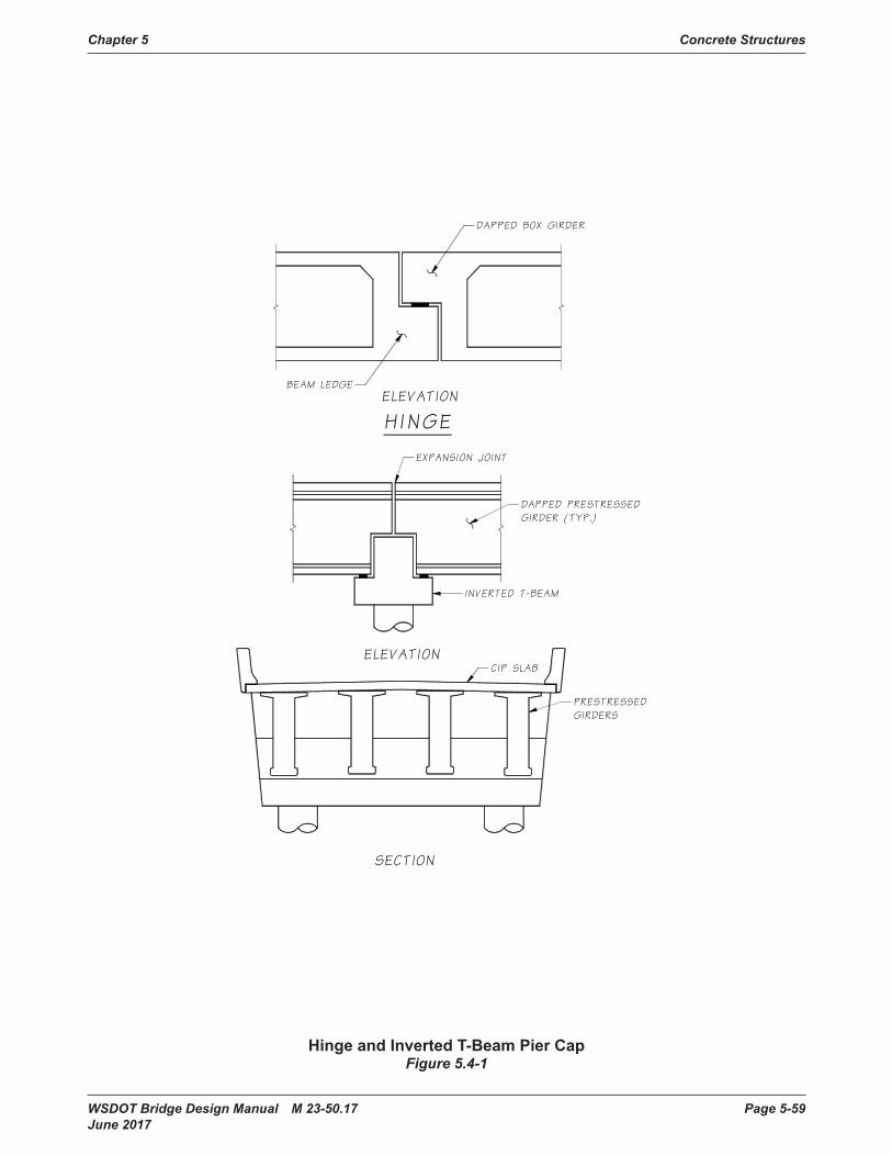
WSDOT Bridge Design Manual M 23-50.17 Page 5-59 June 2017
Chapter 5 Concrete Structures
Hinge and Inverted T-Beam Pier CapFigure 5.4-1
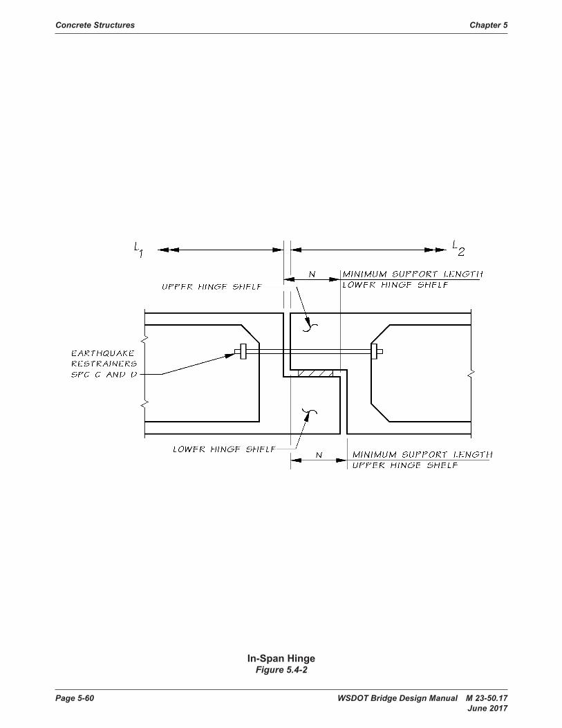
Page 5-60 WSDOT Bridge Design Manual M 23-50.17 June 2017
Concrete Structures Chapter 5
In-Span HingeFigure 5.4-2
WSDOT Bridge Design Manual M 23-50.17 Page 5-61 June 2017
Chapter 5 Concrete Structures
5.5 Bridge WideningsThissectionprovidesgeneralguidanceforthedesignofbridgewidenings.Includedareadditionstothesubstructureandthesuperstructureofreinforcedconcreteboxgirder,flatslab,T-beam,andprestressedconcretegirderbridges.Foradditionalinformation, see ACI Committee Report, Guide for Widening Highway Bridges9.
5.5.1 Review of Existing StructuresA. General Obtainthefollowingdocumentsfromexistingrecordsforpreliminaryreview,
design,andplanpreparation:1. The “As-Built” contract plans,usuallyavailable from the ”Bridge Engineering
Information System” on the Bridge and StructuresOfficewebsite.2. Theoriginalcontractplansandspecialprovisions,whichcanbeobtainedfrom
Engineering Records (Plans Vault), Records Control or the ”Bridge Engineering InformationSystem”ontheBridgeandStructuresOfficewebsite.
3. Check with the Bridge Preservation Unit for records of any unusual movements/rotations and other structural information.
4. Original design calculations, which are stored in State Archives.5. Currentfieldmeasurements.Currentfieldmeasurementsofexistingpier
crossbeamlocationsarerecommendedsothatnewprestressedconcretegirdersarenotfabricatedtooshortortoolong.Thisisparticularlyimportantifpiershavebeenconstructedwithdifferentskews.
6. OriginalandcurrentFoundationReportsfromtheMaterialsLaborfromthePlans Vault.
7. ChangeOrderfilestotheoriginalbridgecontractinRecordsControlUnit.B. Original Contract Plans and Special Provisions Locationandsizeofreinforcement,membersizesandgeometry,locationof
constructionjoints,details,allowabledesignsoilpressure,andtestholedataaregivenontheplans.Originalcontractplanscanbemorelegiblethanthemicrofilmcopies.
The special provisions may include pertinent information that is not covered on the plans or in the AASHTO LRFD Specifications.
C. Original Calculations Theoriginalcalculationsshouldbereviewedforany“specialassumptions”or
officecriteriausedintheoriginaldesign.Theactualstressesinthestructuralmembers,whichwillbeaffectedbythewidening,shouldbereviewed.Thismayaffectthestructuretypeselectedforthewidening.
D. Final Records Formajorwidening/renovationprojects,theFinalRecordsshouldbereviewed
particularlyforinformationabouttheexistingfoundationsandpiles.Sometimesthe piles indicated on the original plans were omitted, revised, or required preboring.FinalRecordsareavailablefromRecordsControlorBridgeRecords(FinalRecordsonsomeolderbridgesmaybeinstorageattheMaterialsLab).

Page 5-62 WSDOT Bridge Design Manual M 23-50.17 June 2017
Concrete Structures Chapter 5
5.5.2 Analysis and Design CriteriaA. General
Each widening represents a unique situation and construction operations may vary betweenwideningprojects.TheguidelinesinthissectionarebasedonyearsofWSDOTdesignexperiencewithbridgewidenings.
1. Appearance
Thewideningofastructureshouldbeaccomplishedinsuchamannerthattheexistingstructuredoesnotlook“addedonto.”Whenthisisnotpossible,considerationshouldbegiventoenclosurewalls,coverpanels,paint,orotheraesthetictreatments.Wherepossibleandappropriate,thestructure’sappearanceshouldbeimprovedbythewidening.
2. Materials
Preferably,materialsusedintheconstructionofthewideningshallhavethesame thermal and elastic properties as the materials in the original structure.
3. Load Distribution and Construction Sequence
Themembersofthewideningshouldbeproportionedtoprovidesimilarlongitudinalandtransverseloaddistributioncharacteristicsastheexistingstructure.Normallythiscanbeachievedbyusingthesamecrosssectionsandmemberlengthsthatwereusedintheexistingstructure.
Theconstructionsequenceanddegreeofinteractionbetweenthewideningandtheexistingstructure,aftercompletion,shallbefullyconsideredindeterminingthedistributionofthedeadloadfordesignofthewideningandstresschecksfor the existing structure.
A suggested construction sequence or stage construction shallbeclearlyshownin the plans to avoid confusion and misinterpretation during construction. A typical construction sequence may involve placing the deck concrete, removing the falsework, placing the concrete for the closure strip, and placing theconcreteforthetrafficbarrier.
4. Specifications
The design of the widening shall conform to the current AASHTO LRFD Bridge Design Specifications and the Standard Specifications.
5. Geometrical Constraints
The overall appearance and geometrical dimensions of the superstructure and columnsofthewideningshouldbethesameorascloseaspossibletothoseofthe existing structure. This is to ensure that the widening will have the same appearanceandsimilarstructuralstiffnessastheoriginalstructure.
6. Overlay
Itshouldbeestablishedatthepreliminaryplanstageifanoverlayisrequiredaspart of the widening.

WSDOT Bridge Design Manual M 23-50.17 Page 5-63 June 2017
Chapter 5 Concrete Structures
7. Strength of the Existing Structure
Areviewofthestrengthofthemainmembersoftheexistingstructureshallbemade for construction conditions utilizing AASHTO LRFD Specifications.
Acheckoftheexistingmainmembersafterattachmentofthewideningshallbemadeforthefinaldesignloadingcondition.
If the existing structural elements do not have adequate strength, consult your Design Unit Manager or in the case of consultants, contact the Consultant Liaison Engineer for appropriate guidance.
Ifsignificantdemolitionisrequiredontheexistingbridge,considerationshouldbegiventorequestingconcretestrengthtestingfortheexistingbridgeandincluding this information in the contract documents.
8. Special Considerations
i. For structures that were originally designed for HS-20 loading, HL-93 shall beusedtodesignthewidening.ForstructuresthatwereoriginallydesignedforlessthanHS-20,considerationshouldbegiventoreplacingthestructureinstead of widening it.
ii. Longitudinal joints are not permitted in order to eliminate potentially hazardousvehiclecontrolproblems.
iii. The Standard SpecificationsdonotpermitfalseworktobesupportedfromtheexistingstructureunlessthePlansandSpecificationsstateotherwise.Thisrequirementeliminatesthetransmissionofvibrationfromtheexistingstructure to the widening during construction. The existing structure may stillbeinservice.
iv. FornarrowwideningswherethePlansandSpecificationsrequirethatthefalseworkbesupportedfromtheoriginalstructure(e.g.,therearenoadditionalgirders,columns,crossbeams,orclosurestrips),thereshallbeno external rigid supports such as posts or falsework from the ground. Supportsfromthegrounddonotpermitthewideningtodeflectwiththeexistingstructurewhentrafficisontheexistingstructure.Thiscausesthe uncured concrete of the widening to crack where it joins the existing structure.Differentialdeadloaddeflectionduringconstructionshallbegiven consideration.
v. PrecastmembersmaybeusedtowidenexistingCIP structures. This method is useful when the horizontal or vertical clearances during constructionareinsufficienttobuildCIPmembers.
vi. The alignment for diaphragms for the widening shall generally coincide with the existing diaphragms.
vii.Whenusingbatteredpiles,estimatethepiletipelevationsandensurethatthey will have ample clearance from all existing piles, utilities, or other obstructions.Alsocheckthatthereissufficientclearancebetweentheexisting structure and the pile driving equipment.
B. Seismic Design Criteria for Bridge Widenings
Seismicdesignofbridgewideningsshallbein accordance with Section 4.3.
Page 5-64 WSDOT Bridge Design Manual M 23-50.17 June 2017
Concrete Structures Chapter 5
C. Substructure
1. Selection of Foundation
a. Thetypeoffoundationtobeusedtosupportthewideningshall generally bethesameasthatoftheexistingstructureunlessotherwiserecommendedbytheGeotechnicalEngineer.Theeffectsofpossibledifferentialsettlementbetweenthenewandtheexistingfoundationsshallbeconsidered.
b. Considerpresentbridgesiteconditionswhendeterminingnewfoundationlocations.Theconditionsinclude:overheadclearanceforpiledrivingequipment,horizontalclearancerequirements,workingroom,pilebatters,channelchanges,utilitylocations,existingembankments,andothersimilar conditions.
2. Scour and Drift
Added piles and columns for widenings at water crossings may alter stream flowcharacteristicsatthebridgesite.Thismayresultinpierscouringtoagreaterdepththanexperiencedwiththeexistingconfiguration.Addedsubstructureelementsmayalsoincreasethepossibilityoftrappingdrift.TheHydraulics Engineer shallbeconsultedconcerningpotentialproblemsrelatedto scour and drift on all widenings at water crossings.
D. Superstructure
1. Camber
Accuratepredictionofdeadloaddeflectionismoreimportantforwideningsthanfornewbridges,sinceitisessentialthatthedeckgradesmatch.
Toobtainasmoothtransitionintransversedirectionofthebridgedeck,thecamberofthegirderadjacenttotheexistingstructureshallbeadjustedforthedifferenceincamberbetweennewandexistingstructure.Alinearinterpolationmaybeusedtoadjustthecamberofthegirderslocatedawayfromtheexistingstructure.ThemultipliersforestimatingcamberofnewstructuremaybetakenasshowninTable5.3.5-1.
2. Closure Strip
Exceptfornarrowdeckslabwideningsaclosurestripisrequiredforallwidenings.Thewidthshallbetheminimumrequiredtoaccommodatethenecessary reinforcement and for form removal. Reinforcement which extends throughtheclosurestripshallbeinvestigated.Shearshallbetransferredacrosstheclosurestripbyshearfrictionand/orshearkeys.
Allfalseworksupportingthewideningshallbereleasedandformworksupportingtheclosurestripshallbesupportedfromtheexistingandnewlywidened structures prior to placing concrete in the closure strip. Because of deckslabcrackingexperiencedinwidenedconcretedecks,closurestripsarerequiredunlessthemid-spandeadloadcamberis½″orless.
Inprestressedconcretegirderbridgewidenings,theclosureshallextendthroughtheintermediateandenddiaphragms.Thediaphragmsshallbemadecontinuous with existing diaphragms.
WSDOT Bridge Design Manual M 23-50.17 Page 5-65 June 2017
Chapter 5 Concrete Structures
3. Stress Levels and Deflections in Existing Structures
Cautionisnecessaryindeterminingthecumulativestresslevels,deflections,andtheneedforshoringinexistingstructuralmembersduringrehabilitationprojects.
The designer shall investigate the adequacy of the existing structure adjacent to the widening for any additional loads, taking into account the loss of removed components.
Forexample,aT-beambridgewasoriginallyconstructedonfalseworkandthefalsework was released after the deckslabconcretegainedstrength.Aspartofamajorrehabilitationproject,thebridgewasclosedtotrafficandtheentiredeckslabwasremovedandreplacedwithoutshoring.Withoutthedeckslab,thestemsbehaveasrectangularsectionswithareduceddepthandwidth.Theexisting stem reinforcement was not originally designed to support the weight of the deckslabwithoutshoring.Afterthenewdeckslabwasplaced,widecracksfromthebottomofthestemopened,indicatingthatthereinforcementwas overstressed. This overstress resulted in a lower load rating for the newly rehabilitatedbridge.ThisexampleshowstheneedtoshoreuptheremainingT-beamstemspriortoplacingthenewdeckslabsothatexcessivedeflectionsdo not occur and overstress in the existing reinforcing steel is prevented.
It is necessary to understand how the original structure was constructed, howtherehabilitatedstructureistobeconstructed,andthecumulativestresslevelsanddeflectionsinthestructurefromthetimeoforiginalconstructionthroughrehabilitation.
E. Stability of Widening
ForrelativelynarrowboxgirderandT-beamwidenings,symmetryabouttheverticalaxisshouldbemaintainedbecauselateralloadsarecriticalduringconstruction.Whensymmetryisnotpossible,usepilecapconnections,lateralconnections,orspecialfalsework.Aminimumoftwowebsisgenerallyrecommendedforboxgirderwidenings.ForT-beamwideningsthatrequireonlyoneadditionalweb,thewebshouldbecenteredattheaxisofsymmetryofthedeck slab.Oftenthewidthoftheclosurestripcanbeadjustedtoaccomplishthis.
5.5.3 Removing Portions of the Existing StructurePortionsoftheexistingstructuretoberemovedshallbeclearlyindicatedontheplans.Whereacleanbreaklineisrequired,a¾″ deepsawcutshallbespecifiedforadeck slabwithnormalwearanda½″ deep saw cut for worn deckslabs.Innocase,however,shallthesawbladecutornickthemaintransversetopslabreinforcement.Thespecialprovisionsshallstatethatcarewillbetakennottodamageanyreinforcementwhichistobesaved.Hydromillingispreferredwherereinforcingbarcoverisshallowandcaneffectivelyremovedelaminateddecksbecauseofthegooddepthcontrolitoffers.Whengreaterdepthsofslabaretoberemoved,specialconsiderationshouldbegiventosecuringexposedreinforcingbarstopreventunduevibrationandsubsequentfatiguecracksfromoccurringinthereinforcingbars.
ThecurrentGeneralSpecialProvisionsshouldbereviewedforotherspecificrequirements on deckslabremoval.

Page 5-66 WSDOT Bridge Design Manual M 23-50.17 June 2017
Concrete Structures Chapter 5
Removalofanyportionofthemainstructuralmembersshouldbeheldtoaminimum.Carefulconsiderationshallbegiventotheconstructionconditions,particularlywhentheremovalaffectstheexistingframesystem.Inextremesituations,preloadingbyjackingisacceptabletocontrolstressesanddeflectionsduringthevariousstagesofremoval and construction. Removal of the main longitudinal deckslabreinforcementshouldbekepttoaminimum.See“SlabRemovalDetail”Figure5.5.4-1forthelimitingcaseforthemaximumallowableremoval.
The plans shallincludeanotethatcriticaldimensionsandelevationsaretobeverifiedinthefieldpriortothefabricationofprecastunitsorexpansionjointassemblies.
Incaseswhereanexistingsidewalkistoberemovedbutthesupportingslabunderthesidewalkistoberetained,Regionpersonnelshouldcheckthefeasibilityofremovingthe sidewalk. Prior to design, Region personnel should make recommendations on acceptableremovalmethodsandrequiredconstructionequipment.Theplansandspecificationsshallthenbepreparedtoaccommodatetheserecommendations.Thiswillensuretheconstructibilityofplandetailsandtheadequacyofthespecifications.
5.5.4 Attachment of Widening to Existing StructureA. General
1. Lap and Mechanical Splices
Toattachawideningtoanexistingstructure,thefirstchoiceistoutilizeexistingreinforcingbarsbysplicingnewbarstoexisting.Lapsplicesormechanicalsplicesshouldbeused.However,itmaynotalwaysbepossibletosplicetoexistingreinforcingbarsandspacinglimitationsmaymakeitdifficultto use mechanical splices.
2. Welding Reinforcement
Existingreinforcingsteelmaynotbereadilyweldable.Mechanicalsplicesshouldbeusedwhereverpossible.Ifweldingistheonlyfeasiblemeans,thechemistryofthereinforcingsteelmustbeanalyzedandacceptableweldingprocedures developed.
3. Drilling Into Existing Structure
Itmaybenecessarytodrillholesandsetdowelsinepoxyresininordertoattach the widening to the existing structure.
Whendrillingintoheavilyreinforcedareas,chippingshouldbespecifiedtoexposethemainreinforcingbars.Ifitisnecessarytodrillthroughreinforcingbarsoriftheholesarewithin4inchesofanexistingconcreteedge,coredrilling shallbespecified.Coredrilledholesshallberoughenedbeforeresinisapplied.Ifthisisnotdone,adriedresidue,whichactsasabondbreakerandreduces the load capacity of the dowel, will remain. Generally, the drilled holes are⅛″indiameterlargerthanthedoweldiameterfor#5andsmallerdowelsand¼″indiameterlargerthanthedoweldiameterfor#6andlargerdowels.
Inspecialapplicationsrequiringdrilledholesgreaterthan1½″diameterordeeperthan2′,coredrillingshallbespecified.Theseholesshallalsobeintentionally roughened prior to applying epoxy resin.

WSDOT Bridge Design Manual M 23-50.17 Page 5-67 June 2017
Chapter 5 Concrete Structures
Core drilled holes shallhaveaminimumclearanceof3″fromtheedgeoftheconcreteand1″clearancefromexistingreinforcingbarsintheexistingstructure. These clearances shallbenotedintheplans.
4. Dowelling Reinforcing Bars Into the Existing Structure
a. Dowelbarsshallbesetwithanapprovedepoxyresin.Theexistingstructuralelementshallbecheckedforitsadequacytotransmittheloadtransferredtoitfromthedowelbars.
b. Dowelspacingandedgedistanceaffecttheallowabletensiledowelloads.Allowabletensileloads,dowelbarembedment,anddrilledholesizesforreinforcingbars(Grade60)usedasdowelsandsetwithanapprovedepoxyresinareshowninTable5.5.4-1.Thesevaluesarebasedonanedgeclearancegreaterthan3″,adowelspacinggreaterthan6″,andareshownforbothuncoatedandepoxycoateddowels.Table5.5.4-2listsdowelembedmentlengthswhenthedowelspacingislessthan6″.NotethatinTable5.5.4-2theedgeclearanceisequaltoorgreaterthan3″,becausethisis the minimum edge clearance for a drilled hole from a concrete edge.
Ifitisnotpossibletoobtaintheseembedments,suchasfortrafficrailingdowelsintoexistingdeckslabs,theallowableloadonthedowelshallbereducedbytheratiooftheactualembedmentdividedbytherequiredembedment.
c. TheembedmentsshowninTable5.5.4-1andTable5.5.4-2arebasedondowelsembeddedinconcretewithƒ′c=4,000 psi.
Bar Size
Allowable Design Tensile Load, T* (kips)
Drill Hole Size (in)
Required Embedment, Le
Uncoated (in) Epoxy Coated (in)#4 12 .0 ⅝ 7 8#5 18 .6 ¾ 8 9#6 26 .4 1 9 10#7 36 .0 1⅛ 11 12#8 47 .4 1¼ 13 14 .5#9 60 .0 1⅜ 16 17½
#10 73 .6 1½ 20 22#11 89 .0 1⅝ 25 28
* Allowable Tensile Load (Strength Design) = (ƒy)(As) .
Allowable Tensile Load for Dowels Set With Epoxy Resin ƒ′c = 4,000 psi, Grade 60 Reinforcing Bars, Edge Clearance ≥ 3″, and Spacing ≥ 6″
Table 5.5.4-1
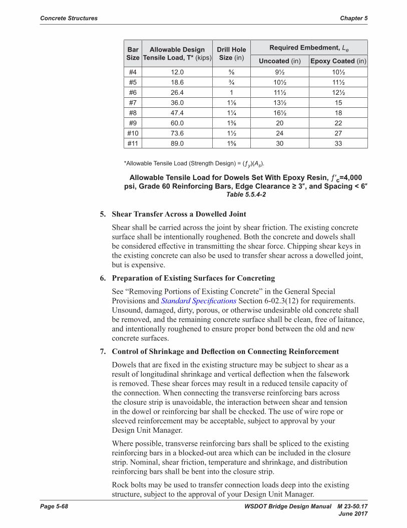
Page 5-68 WSDOT Bridge Design Manual M 23-50.17 June 2017
Concrete Structures Chapter 5
Bar Size
Allowable Design Tensile Load, T* (kips)
Drill Hole Size (in)
Required Embedment, Le
Uncoated (in) Epoxy Coated (in)#4 12 .0 ⅝ 9½ 10½#5 18 .6 ¾ 10½ 11½#6 26 .4 1 11½ 12½#7 36 .0 1⅛ 13½ 15#8 47 .4 1¼ 16½ 18#9 60 .0 1⅜ 20 22
#10 73 .6 1½ 24 27#11 89 .0 1⅝ 30 33
*Allowable Tensile Load (Strength Design) = (ƒy)(As) .
Allowable Tensile Load for Dowels Set With Epoxy Resin, ƒ′c=4,000 psi, Grade 60 Reinforcing Bars, Edge Clearance ≥ 3″, and Spacing < 6″
Table 5.5.4-2
5. Shear Transfer Across a Dowelled Joint
Shear shallbecarriedacrossthejointbyshearfriction. The existing concrete surfaceshallbe intentionally roughened. Both the concrete and dowels shall beconsideredeffectivein transmitting the shear force. Chipping shear keys in theexistingconcretecanalsobeusedtotransfershearacrossadowelledjoint,butisexpensive.
6. Preparation of Existing Surfaces for Concreting
See “Removing Portions of Existing Concrete” in the General Special Provisions and Standard Specifications Section 6-02.3(12) for requirements. Unsound,damaged,dirty,porous,orotherwiseundesirableoldconcreteshall beremoved,andtheremainingconcretesurfaceshallbeclean,freeoflaitance,andintentionallyroughenedtoensureproperbondbetweentheoldandnewconcrete surfaces.
7. Control of Shrinkage and Deflection on Connecting Reinforcement
Dowelsthatarefixedintheexistingstructuremaybesubjecttoshearasaresultoflongitudinalshrinkageandverticaldeflectionwhenthefalseworkis removed. These shear forces may result in a reduced tensile capacity of theconnection.Whenconnectingthetransversereinforcingbarsacrosstheclosurestripisunavoidable,theinteractionbetweenshearandtensioninthedowelorreinforcingbarshallbechecked.Theuseofwireropeorsleevedreinforcementmaybeacceptable,subjecttoapprovalbyyourDesign Unit Manager.
Wherepossible,transversereinforcingbarsshallbesplicedtotheexistingreinforcingbarsinablocked-outareawhichcanbeincludedintheclosurestrip.Nominal,shearfriction,temperatureandshrinkage,anddistributionreinforcingbarsshallbebentintotheclosurestrip.
Rockboltsmaybeusedtotransferconnectionloadsdeepintotheexistingstructure,subjecttotheapprovalofyourDesignUnitManager.
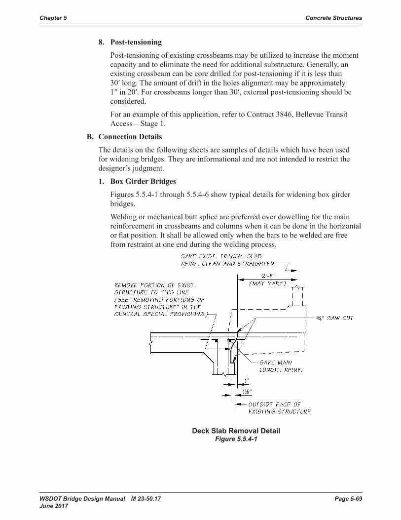
WSDOT Bridge Design Manual M 23-50.17 Page 5-69 June 2017
Chapter 5 Concrete Structures
8. Post-tensioning
Post-tensioningofexistingcrossbeamsmaybeutilizedtoincreasethemomentcapacityandtoeliminatetheneedforadditionalsubstructure.Generally,anexistingcrossbeamcanbecoredrilledforpost-tensioningifitislessthan30′long.Theamountofdriftintheholesalignmentmaybeapproximately1″in20′.Forcrossbeamslongerthan30′,externalpost-tensioningshouldbeconsidered.
For an example of this application, refer to Contract 3846, Bellevue Transit Access – Stage 1.
B. Connection Details
Thedetailsonthefollowingsheetsaresamplesofdetailswhichhavebeenusedforwideningbridges.Theyareinformationalandarenotintendedtorestrictthedesigner’sjudgment.
1. Box Girder Bridges
Figures5.5.4-1through5.5.4-6showtypicaldetailsforwideningboxgirderbridges.
Weldingormechanicalbuttsplicearepreferredoverdowellingforthemainreinforcementincrossbeamsandcolumnswhenitcanbedoneinthehorizontalorflatposition.Itshallbeallowedonlywhenthebarstobeweldedarefreefrom restraint at one end during the welding process.
Deck Slab Removal DetailFigure 5.5.4-1
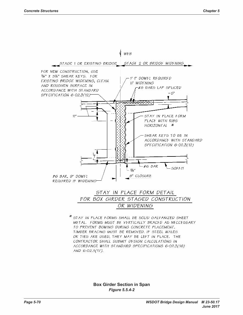
Page 5-70 WSDOT Bridge Design Manual M 23-50.17 June 2017
Concrete Structures Chapter 5
Box Girder Section in SpanFigure 5.5.4-2
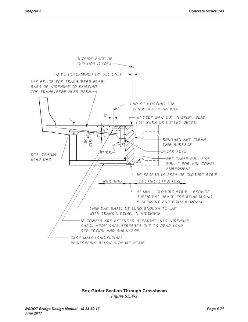
WSDOT Bridge Design Manual M 23-50.17 Page 5-71 June 2017
Chapter 5 Concrete Structures
Box Girder Section Through CrossbeamFigure 5.5.4-3
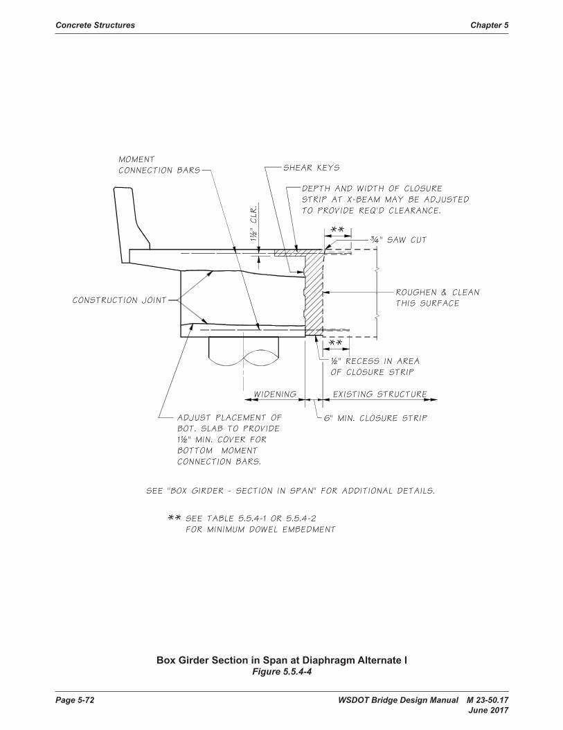
Page 5-72 WSDOT Bridge Design Manual M 23-50.17 June 2017
Concrete Structures Chapter 5
Box Girder Section in Span at Diaphragm Alternate I Figure 5.5.4-4

WSDOT Bridge Design Manual M 23-50.17 Page 5-73 June 2017
Chapter 5 Concrete Structures
Box Girder Section in Span at Diaphragm Alternate IIFigure 5.5.4-5
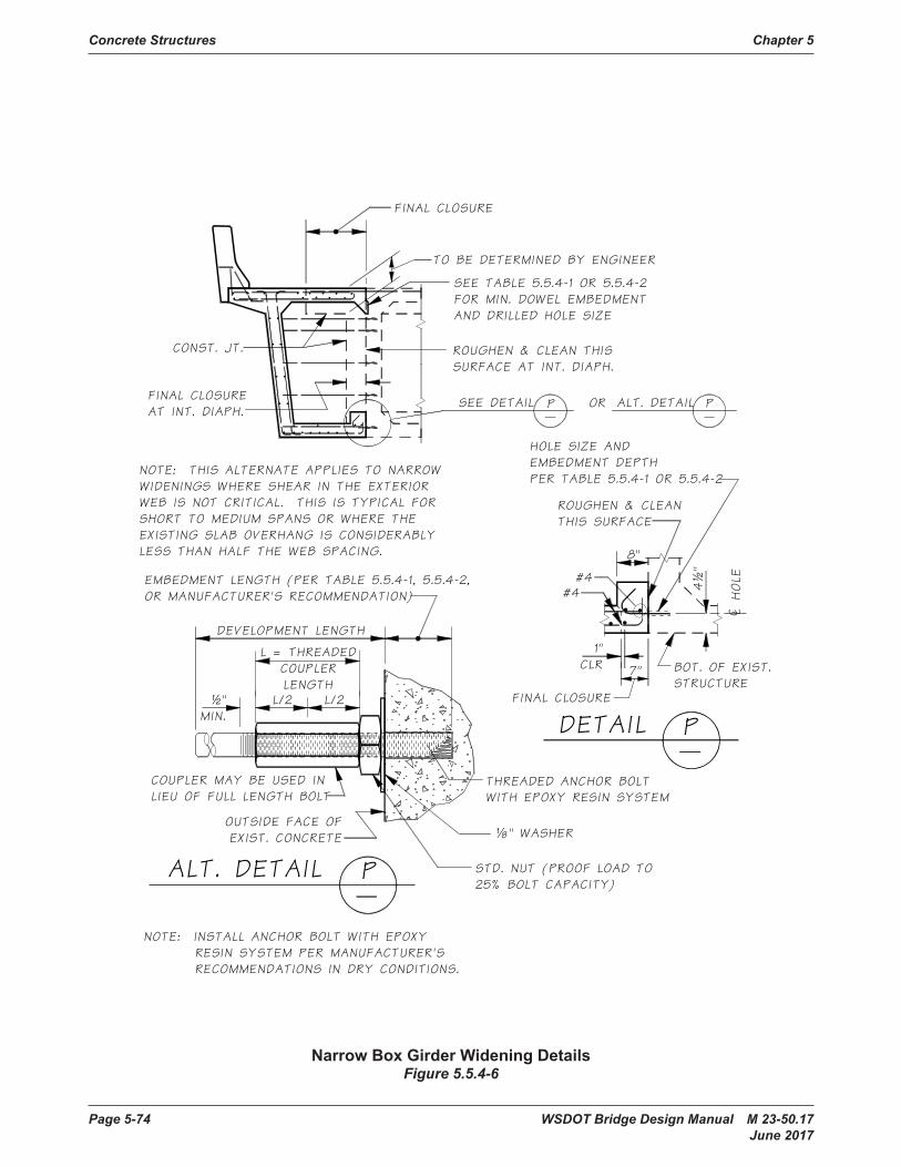
Page 5-74 WSDOT Bridge Design Manual M 23-50.17 June 2017
Concrete Structures Chapter 5
Narrow Box Girder Widening DetailsFigure 5.5.4-6
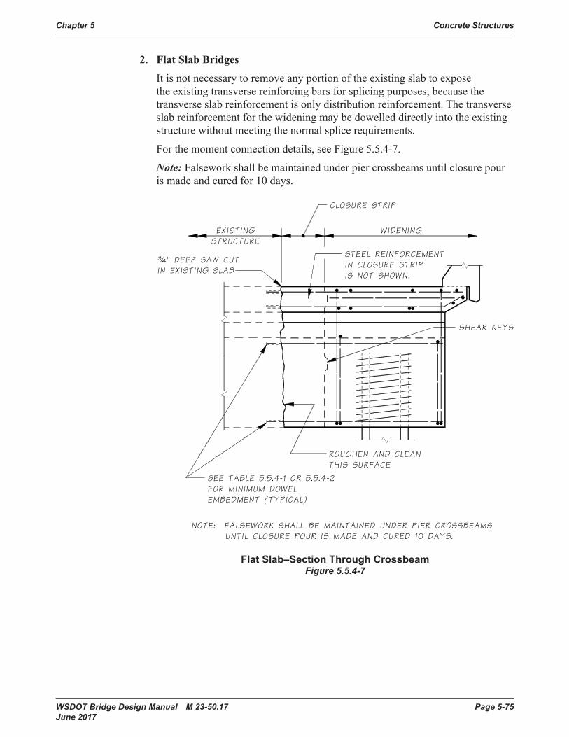
WSDOT Bridge Design Manual M 23-50.17 Page 5-75 June 2017
Chapter 5 Concrete Structures
2. Flat Slab Bridges
Itisnotnecessarytoremoveanyportionoftheexistingslabtoexposetheexistingtransversereinforcingbarsforsplicingpurposes,becausethetransverseslabreinforcementisonlydistributionreinforcement.Thetransverseslabreinforcementforthewideningmaybedowelleddirectlyintotheexistingstructure without meeting the normal splice requirements.
For the moment connection details, see Figure 5.5.4-7.
Note:Falseworkshallbemaintainedunderpiercrossbeamsuntilclosurepouris made and cured for 10 days.
Flat Slab–Section Through CrossbeamFigure 5.5.4-7

Page 5-76 WSDOT Bridge Design Manual M 23-50.17 June 2017
Concrete Structures Chapter 5
3. T-Beam Bridges
Usedetailssimilartothoseforboxgirderbridgesforcrossbeamconnections.SeeFigure5.5.4-8forslabconnectiondetail.
T-Beam–Section in Span Figure 5.5.4-8
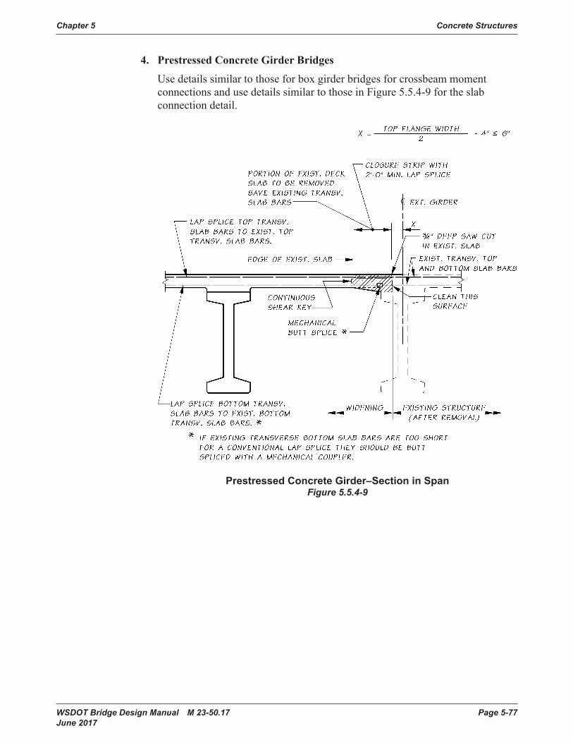
WSDOT Bridge Design Manual M 23-50.17 Page 5-77 June 2017
Chapter 5 Concrete Structures
4. Prestressed Concrete Girder Bridges
UsedetailssimilartothoseforboxgirderbridgesforcrossbeammomentconnectionsandusedetailssimilartothoseinFigure5.5.4-9fortheslabconnection detail.
Prestressed Concrete Girder–Section in SpanFigure 5.5.4-9

Page 5-78 WSDOT Bridge Design Manual M 23-50.17 June 2017
Concrete Structures Chapter 5
5.5.5 Expansion JointsThedesignershoulddetermineifexistingexpansionjointscanbeeliminated.Itwillbenecessarytodeterminewhatmodificationstothestructurearerequiredtoprovideanadequate functional system when existing joints are eliminated.
For expansion joint design, see Section 9.1 Expansion Joints. Very often on widening projectsitisnecessarytochipouttheexistingconcretedeckandrebuildthejoint.Figures 5.5.5-1 and5.5.5-2showdetailsforrebuildingjointopeningsforcompressionseal expansion joints.
Ifawideningprojectincludesanoverlay,theexpansionjointmayhavetoberaised,modifiedorreplaced.SeetheJointSpecialistforplandetailsthatarecurrentlybeingusedtomodifyorretrofitexistingexpansionjoints.
¼"(TYP.)
½"
"A"
USE É" EDGER
COMPRESSION SEAL
SAVE EXISTINGREINFORCEMENT
REMOVE TO ¾" CLR.MIN. BEHIND EXISTINGREINFORCEMENT
REMOVE SHADED PORTION OFEXISTING SLAB. REBUILD WITHCONCRETE FOR EXPANSIONJOINTS TO FORM A SEAT FORTHE COMPRESSION SEAL.
Expansion Joint Detail Shown for Compression Seal With Existing Reinforcing Steel Saved
Figure 5.5.5-1

WSDOT Bridge Design Manual M 23-50.17 Page 5-79 June 2017
Chapter 5 Concrete Structures
90°
VARIES
4½"
2"
3"MIN.
2½" CLR.
60°
EXISTING OPENING
BACK OFPAVT. SEAT
1 £#4 @ 1'-6" CTRS. PLACEBETWEEN CURB ONLY (TYP.)(INSERT VARIABLE LENGTHLEG IN Ð"ø HOLE.)
2 £#4 WITH2'-0" MIN. SPLICE
CONCRETE FOREXPANSION JOINTS
SIDE OF NEWDIAPHRAGM
DRILL Ð"ø HOLE FOR #4 REINF. BAR.SET WITH EPOXY RESIN (TYP.).(PLACE BETWEEN CURBS ONLY)
1
4" MIN. (REMOVE TOSOUND CONCRETE)
Expansion Joint Detail Shown for Compression Seal With New Reinforcing Steel Added
Figure 5.5.5-2
5.5.6 Possible Future Widening for Current DesignsFor current projects that include sidewalks, provide a smooth rather than a roughened constructionjointbetweenthesidewalkandtheslab.
5.5.7 Bridge Widening FalseworkForwideningswhichdonothaveadditionalgirders,columns,crossbeams,orclosurepours,falseworkshouldbesupportedbytheexistingbridge.Thereshouldbenoexternal support from the ground. The reason is that the ground support will not allow thewideningtodeflecttheexistingbridgewhentrafficisonthebridge.Thiswillcausethe“green”concretetocrackwhereitjoinstheexistingbridge.The designer should contact the Bridge Construction Support Unit regarding falsework associated with widenings.
5.5.8 Existing Bridge WideningsAppendix5-B3listsbridgewideningsprojectsthatmaybeusedasdesignaidsforthedesigners.Theseshouldnotbeconstruedastheonlyacceptablemethodsofwidening;thereisnosubstituteforthedesigner’screativityoringenuityinsolvingthechallengesposedbybridgewidenings.
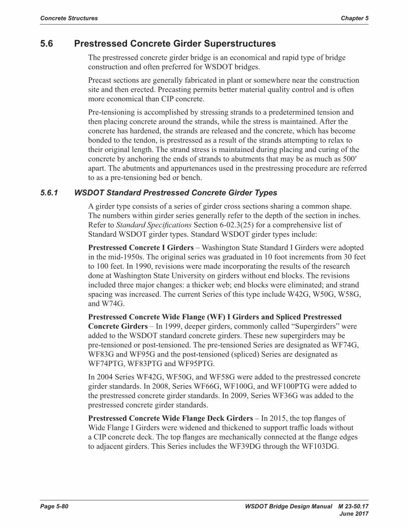
Page 5-80 WSDOT Bridge Design Manual M 23-50.17 June 2017
Concrete Structures Chapter 5
5.6 Prestressed Concrete Girder SuperstructuresTheprestressedconcretegirderbridgeisaneconomicalandrapidtypeofbridgeconstructionandoftenpreferredforWSDOTbridges.
Precastsectionsaregenerallyfabricatedinplantorsomewhereneartheconstructionsiteandthenerected.Precastingpermitsbettermaterialqualitycontrolandisoftenmore economical than CIP concrete.
Pre-tensioningisaccomplishedbystressingstrandstoapredeterminedtensionandthen placing concrete around the strands, while the stress is maintained. After the concretehashardened,thestrandsarereleasedandtheconcrete,whichhasbecomebondedtothetendon,isprestressedasaresultofthestrandsattemptingtorelaxtotheir original length. The strand stress is maintained during placing and curing of the concretebyanchoringtheendsofstrandstoabutmentsthatmaybeasmuchas500′apart.Theabutmentsandappurtenancesusedintheprestressingprocedurearereferredtoasapre-tensioningbedorbench.
5.6.1 WSDOT Standard Prestressed Concrete Girder TypesA girder type consists of a series of girder cross sections sharing a common shape. Thenumberswithingirderseriesgenerallyrefertothedepthofthesectionininches.Refer to Standard Specifications Section 6-02.3(25) for a comprehensive list of StandardWSDOTgirdertypes.StandardWSDOTgirdertypesinclude:
Prestressed Concrete I Girders – Washington State Standard I Girders were adopted in the mid-1950s. The original series was graduated in 10 foot increments from 30 feet to 100 feet. In 1990, revisions were made incorporating the results of the research doneatWashingtonStateUniversityongirderswithoutendblocks.Therevisionsincludedthreemajorchanges:athickerweb;endblockswereeliminated;andstrandspacing was increased. The current Series of this type include W42G, W50G, W58G, and W74G.
Prestressed Concrete Wide Flange (WF) I Girders and Spliced Prestressed Concrete Girders – In 1999, deeper girders, commonly called “Supergirders” were addedtotheWSDOTstandardconcretegirders.Thesenewsupergirdersmaybepre-tensioned or post-tensioned. The pre-tensioned Series are designated as WF74G, WF83G and WF95G and the post-tensioned (spliced) Series are designated as WF74PTG, WF83PTG and WF95PTG.
In 2004 Series WF42G, WF50G, and WF58G were added to the prestressed concrete girder standards. In 2008, Series WF66G, WF100G, and WF100PTG were added to the prestressed concrete girder standards. In 2009, Series WF36G was added to the prestressed concrete girder standards.
Prestressed Concrete Wide Flange Deck Girders–In2015,thetopflangesofWideFlangeIGirderswerewidenedandthickenedtosupporttrafficloadswithoutaCIPconcretedeck.Thetopflangesaremechanicallyconnectedattheflangeedgesto adjacent girders. This Series includes the WF39DG through the WF103DG.

WSDOT Bridge Design Manual M 23-50.17 Page 5-81 June 2017
Chapter 5 Concrete Structures
Prestressed Concrete Wide Flange Thin Deck Girders–In2015,thetopflangesofwideflangeIgirderswerewidenedtocreateagirderwhichwouldsupportaCIPconcrete deck placement without formwork. This Series includes the WF36TDG through the WF100TDG.
Deck Bulb Tee Girders–Thistypeofgirderhasatopflangedesignedtosupporttrafficloadsandaremechanicallyconnectedattheflangeedgestoadjacentgirders.They include Series W35DG, W41DG, W53DG and W65DG.
Prestressed Concrete Slab Girders–Prestressedconcreteslabgirdersareavailablein heights ranging from 12 inches to 30 inches.
Prestressed Concrete Tub Girders–In2004prestressedconcretetubgirderswereadded as standard girders.
All WSDOT prestressed concrete girders are high performance high strength concrete girders.Theygenerallyrelyonhighstrengthconcretetobeeffectiveforthespansexpected as a single piece. The approximate ranges of maximum span lengths are as shown in Table5.6.1-1 and Appendices 5.6-A1-1 to 5.6-A1-9.
Standard drawings for WSDOT prestressed concrete girders are shown in the BridgeStandardDrawingswebsite(www.wsdot.wa.gov/Bridge/Structures/StandardDrawings.htm).

Page 5-82 WSDOT Bridge Design Manual M 23-50.17 June 2017
Concrete Structures Chapter 5
Type Depth (in)
Area (in2)
Iz (in4)
Yb (in)
Wt
(k/ft)
Volume to Surface Ratio
(in)
Max. Span Capability (ft)
Max. Length (252 kips Limit) (ft)
W42G 42 .00 373 .25 76092 18 .94 0 .428 2 .77 85 -W50G 50 .00 525 .5 164958 22 .81 0 .602 3 .12 115 -W58G 58 .00 603 .5 264609 28 .00 0 .692 3 .11 130 -W74G 73 .50 746 .7 546110 38 .08 0 .856 2 .90 150 -
WF36G 36 .00 690 .8 124772 17 .54 0 .792 3 .24 105 -WF42G 42 .00 727 .5 183642 20 .36 0 .834 3 .23 120 -WF50G 50 .00 776 .5 282559 24 .15 0 .890 3 .22 140 -WF58G 58 .00 825 .5 406266 27 .97 0 .946 3 .21 155 -WF66G 66 .00 874 .5 556339 31 .80 1 .002 3 .20 165 -WF74G 74 .00 923 .5 734356 35 .66 1 .058 3 .19 175 -WF83G 82 .63 976 .4 959393 39 .83 1 .119 3 .19 190 -WF95G 94 .50 1049 .1 1328995 45 .60 1 .202 3 .18 190 -
WF100G 100 .00 1082 .8 1524912 48 .27 1 .241 3 .17 205 20312″ Slab 12 .00 566 .0 6772 6 .01 0 .649 4 .82 30 -18″ Slab 18 .00 658 .6 21922 9 .01 0 .755 3 .84 45 -24” Slab 24 .00 745 .8 48331 12 .02 0 .855 3 .91 60 -26″ Slab 26 .00 840 .3 63080 13 .02 0 .963 4 .32 65 -30″ Slab 30 .00 1027 .6 104791 15 .01 1 .177 4 .72 75 -U54G4 54 .00 1038 .8 292423 20 .97 1 .190 3 .51 130 -U54G5 54 .00 1110 .8 314382 19 .81 1 .273 3 .47 130 -U66G4 66 .00 1208 .5 516677 26 .45 1 .385 3 .51 150 -U66G5 66 .00 1280 .5 554262 25 .13 1 .467 3 .47 150 -U78G4 78 .00 1378 .2 827453 32 .06 1 .579 3 .51 170 160U78G5 78 .00 1450 .2 885451 30 .62 1 .662 3 .48 170 152
UF60G4 60 .00 1207 .7 483298 26 .03 1 .384 3 .48 150 -UF60G5 60 .00 1279 .7 519561 24 .74 1 .466 3 .45 150 -UF72G4 72 .00 1377 .4 787605 31 .69 1 .578 3 .48 160 160UF72G5 72 .00 1449 .4 844135 30 .26 1 .661 3 .45 170 152UF84G4 84 .00 1547 .1 1190828 37 .42 1 .773 3 .48 180 142UF84G5 84 .00 1619 .1 1272553 35 .89 1 .855 3 .46 180 136
Section Properties of WSDOT Standard Prestressed Concrete GirdersTable 5.6.1-1

WSDOT Bridge Design Manual M 23-50.17 Page 5-83 June 2017
Chapter 5 Concrete Structures
5.6.2 Design CriteriaWSDOT design criteria for prestressed concrete girder superstructures are given in Table5.6.2-1.
AASHTO LRFD Section 5.12.3.3 “Bridges Composed of Simple Span Precast Girders MadeContinuous”allowsforsomedegreeofcontinuityforloadsappliedonthebridgeafterthecontinuitydiaphragmshavebeencastandcured.Thisassumptionisbasedontheageofthegirderwhencontinuityisestablished,anddegreeofcontinuityatvariouslimit states. Both degree of continuity and time of continuity diaphragm casting mayresultincontractualanddesignissues.DesigningthesetypesofbridgesfortheenvelopeofsimplespanandcontinuousspansforapplicablepermanentandtransientloadsistheapproachusedbyWSDOTasithasyieldedgoodresults.
Design Specifications
AASHTO LRFD Specifications and WSDOT Bridge Design Manual M 23-50
Design Method Prestressed concrete members shall be designed for service limit state for allowable stresses and checked for strength limit state for ultimate capacity .
Superstructure Continuity
Prestressed concrete girder superstructures shall be designed for the envelope of simple span and continuous span loadings for all permanent and transient loads. Loads applied before establishing continuity (typically before placement of continuity diaphragms) need only be applied as a simple span loading. Continuity reinforcement shall be provided at supports for loads applied after establishing continuity.
Loads and Load Factors
Service, Strength, Fatigue, and Extreme Event Limit State loads and load combinations shall be in accordance with AASHTO LRFD Specifications
Allowable Stresses Table 5.2.1-1Prestress Losses Section 5 .1 .4Shear Design AASHTO LRFD Section 5 .7 and Section 5 .2 .2 .BShipping and Handling
Section 5 .6 .3
Continuous Structure Configuration
Girder types and spacing shall be identical in adjacent spans. Girder types and spacing may be changed at expansion joints.
Girder End Skew Angle
Girder end skew angles for prestressed concrete slabs, deck bulb-tees, WFDG girders, WFTDG girders and tubs shall be limited to 30°. Girder end skew angles for all other prestressed concrete girders shall be limited to 45°.
Intermediate Diaphragms
CIP concrete intermediate diaphragms shall be provided for all prestressed concrete girder bridges (except slabs) as shown below:• 1/5 points of span for span length > 160′-0″.• ¼ points of span for 120′-0″ < span length ≤ 160′-0″.• ⅓ points of span for 80′-0″ < span length ≤ 120′-0″.• Midpoint of span for 40′-0″ < span length ≤ 80′-0″.• No diaphragm requirement for span length ≤ 40′-0″.
Intermediate diaphragms shall be either partial or full depth as described in Section 5 .6 .4 .C .4 .
Design Criteria for Prestressed Concrete GirdersTable 5.6.2-1

Page 5-84 WSDOT Bridge Design Manual M 23-50.17 June 2017
Concrete Structures Chapter 5
A. Support Conditions
Theprestressedconcretegirdersareassumedtobesupportedonrigidpermanentsimplesupports.Thesesupportscanbeeitherbearingseatsorelastomericpads.Thedesignspanlengthisthedistancecentertocenterofbearingsforsimplespans.Forcontinuousspanserectedonfalsework(raisedcrossbeam),theeffectivepointofsupportforgirderdesignisassumedtobethefaceofthecrossbeam.Forcontinuousspansoncrossbeams(droppedorsemi-droppedcrossbeam),thedesignspanlengthisusuallythedistancecentertocenteroftemporarybearings.
B. Composite Action
1. General
The sequence of construction and loading is extremely important in the design of prestressed concrete girders. The composite section has a much larger capacitythanthebasicgirdersectionbutitcannottakeloadsuntilthedeckslabhasobtainedadequatestrength.Assumptionsusedincomputingcompositesection properties are shown in Figure 5.6.2-1.
2. Load Application
The following sequence and method of applying loads is typically used in girderanalysis:
a. Girder dead load is applied to the girder section.
b. Diaphragmdeadloadisappliedtothegirdersection.
c. Deckslabdeadloadisappliedtothegirdersection.
d. Superimposeddeadloads(suchasbarriers,sidewalksandoverlays)andlive loads are applied to the composite section.
Thedeadloadofonetrafficbarrierorsidewalkmaybedividedamongamaximumofthreegirderwebs.
3. Composite Section Properties
ACIPconcretebridgedeckformsthetopflangeofthecompositegirderinprestressedconcretegirderbridgeconstruction.
i. Effective and Transformed Flange Width
TheeffectiveflangewidthofaconcretebridgedeckforcomputingcompositesectionpropertiesshallbeinaccordancewithAASHTOLRFD Section 4.6.2.6.TheeffectiveflangewidthshallbereducedbytheratioEslab/Egirdertoobtainthetransformedflangewidth.TheeffectivemodulusofthecompositesectionwiththetransformedflangewidthisthenEgirder.
ii. Effective Flange Thickness
Theeffectiveflangethicknessofaconcretebridgedeckforcomputingcompositesectionpropertiesshallbethedeckthicknessreducedby½″toaccountforwearing.Whereabridgewillhaveanoverlayappliedpriortotrafficbeingallowedonthebridge,thefulldeckthicknessmaybeusedaseffectiveflangethickness.
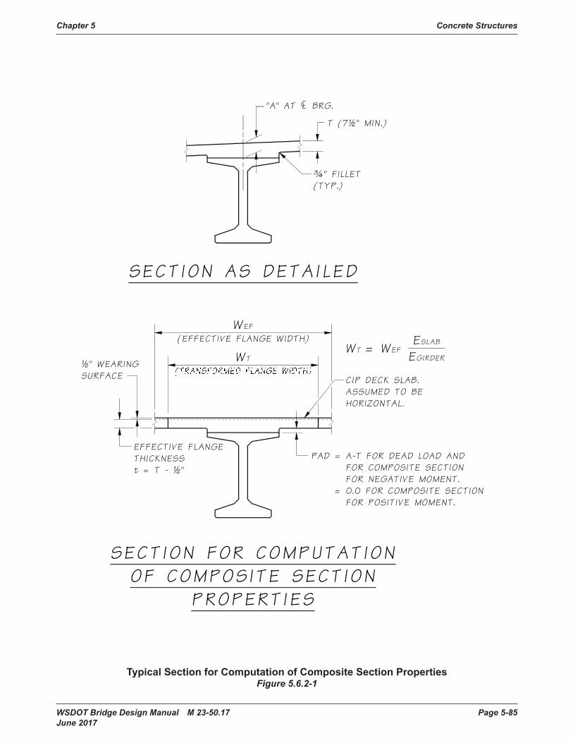
WSDOT Bridge Design Manual M 23-50.17 Page 5-85 June 2017
Chapter 5 Concrete Structures
(EFFECTIVE FLANGE WIDTH)WEF
WT½" WEARINGSURFACE
EFFECTIVE FLANGETHICKNESSt = T - ½"
"A" AT ¢ BRG.
T (7½" MIN.)
ESLAB
EGIRDERWT = WEF
¾" FILLET(TYP.)
CIP DECK SLAB.ASSUMED TO BE HORIZONTAL.
SECTION FOR COMPUTATIONOF COMPOSITE SECTION
PROPERTIES
SECTION AS DETAILED
A-T FOR DEAD LOAD ANDFOR COMPOSITE SECTIONFOR NEGATIVE MOMENT.0.0 FOR COMPOSITE SECTIONFOR POSITIVE MOMENT.
PAD =
=
Typical Section for Computation of Composite Section PropertiesFigure 5.6.2-1

Page 5-86 WSDOT Bridge Design Manual M 23-50.17 June 2017
Concrete Structures Chapter 5
iii. Flange Position
AnincreaseddimensionfromtopofgirdertotopofbridgedeckatcenterlineofbearingatcenterlineofgirdershallbeshowninthePlans.Thisiscalledthe“A”dimension.Itaccountsfortheeffectsofgirdercamber,verticalcurve,deckcrossslope,etc.SeeAppendix 5-B1 for method of computing.
For purposes of calculating composite section properties for negative moments,thepad/haunchheightbetweenbottomofdeckandtopofgirdershallbetakenasthe“A”dimensionminustheflangethickness“T”atintermediatepiersupportsandshallbereducedbygirdercamberasappropriate at other locations.
For purposes of calculating composite section properties for positive moments,thebottomofthebridgedeckshallbeassumedtobedirectlyonthetopofthegirder.Thisassumptionmayprovetobetrueatcenterofspanwhereexcessgirdercamberoccurs.
iv. Section Dead Load
Thebridgedeckdeadloadtobeappliedtothegirdershallbebasedonthefullbridgedeckthickness.Thefulleffectivepad/haunchweightshallbeaddedtothatloadoverthefulllengthofthegirder.Thefulleffectivepadorhaunchheightistypicallythe“A”dimensionminustheflangethickness“T”,butmaybehigheratmidspanforacrestverticalcurve.
C. Design Procedure
1. General
The WSDOT Prestressed concrete girder design computer program PGSuper is the preferred method for design.
2. Stress Conditions
ThestresslimitsasdescribedinTable5.2.1-1 shall not be exceeded for prestressed concrete girders at all stages of construction and in service. The stagesofconstructionforwhichstresslimitsshallbecheckedshallinclude,butnotbelimitedtothefollowing:
a. Prestressing release at casting yard using Service I Limit State
b. LiftingatcastingyardusingServiceILimitState.Deadloadimpactneednotbeconsideredduringlifting.Thischeckshallbedoneinaccordancewith Section 5.6.3.C.2.
c. Shipping for a girder with impact using Service I Limit State. A dead loadimpactof20percentshallbeincludedactingbothupanddown.Theangleofinclinationshallbetheequilibriumtiltanglecomputedforlateralstabilitywitharoadwaysuperelevationof2percent.Thischeckshallbedone in accordance with Section 5.6.3.D.6. This condition represents the girder traveling along a straight road at a typical 2% superelevation with dynamicloadeffects.

WSDOT Bridge Design Manual M 23-50.17 Page 5-87 June 2017
Chapter 5 Concrete Structures
d. Shipping for a girder without impact using Service I Limit State. Dead load impact,windandcentrifugalforcesneednotbeincluded.Theangleof inclinationshallbetheequilibriumtiltanglecomputedforlateralstabilitywith a roadway superelevation of 6 percent.Thischeckshallbedoneinaccordance with Section 5.6.3.D.6. This condition represents the girder going slowly through a corner with a 6 percent superelevation.
e. Deck and diaphragm placement using Service I Limit State
f. Final condition without live load using Service I Limit State
g. Final condition with live load using Service I Limit State for compressive stresses and Service III Limit State for tensile stresses
h. Final condition with live load using Fatigue I Limit State
When dead load impact is included in constructionchecks,thedeflectionandsweepinducedbythedynamiccomponentneednotbeconsideredwhenperformingstressandstabilitychecks.
D. Standard Strand Locations
Standard strand locations of typical prestressed concrete girders are shown in Figure 5.6.2-2 theBridgeStandardDrawingswebsite(www.wsdot.wa.gov/Bridge/Structures/StandardDrawings.htm).
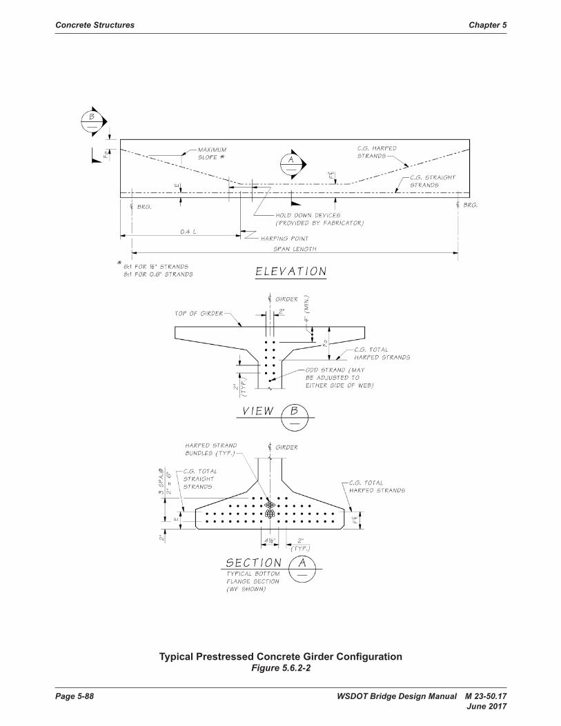
Page 5-88 WSDOT Bridge Design Manual M 23-50.17 June 2017
Concrete Structures Chapter 5
Typical Prestressed Concrete Girder ConfigurationFigure 5.6.2-2

WSDOT Bridge Design Manual M 23-50.17 Page 5-89 June 2017
Chapter 5 Concrete Structures
E. Girder End Types
There are four typical end types for prestressed concrete girders. Due to the extremedepthoftheWF83G,WF95G,andWF100Ggirders,andpossibleendofgirdertiltatthepiersforprofilegrades,thedesignerwillneedtopayparticularattentiontodetailstoassurethegirderswillfitandperformasintended.
Theendtypesdesignsmayrequiremodificationforbridgesecurity.Thespacebetweengirdersattheabutmentmayrequireomissionbyextendingthediaphragmtothefaceoftheabutmentstem.CoordinatewiththeWSDOTStateBridgeandStructuresArchitectduringfinaldesignwhererequired.
Thefourendtypesareshownasfollows:
1. End Type A
End Type A as shown in Figure 5.6.2-3 is for cantilever end piers with an end diaphragmcastontheendofthegirders.EndTypeAhasarecessatthebottomofthegirderneartheendforanelastomericbearingpad.SeeBridgeStandardDrawings 5.6-A4-12 and 5.6-A9-9forbearingpaddetails.Therecessatthecenterlineofbearingis0.5″deep.Thisrecessistobeusedforprofilegradesuptoandincluding4percent.Therecessistobereplacedbyanembeddedsteelplateflushwiththebottomofthegirderforgradesover4percent.Ataperedbearingplate,withstopsattheedgestocontaintheelastomericpad,canbeweldedorboltedtotheembeddedplatetoprovidealevelbearingsurface.
Reinforcingbarsandpre-tensionedstrandsprojectfromtheendofthegirder.Thedesignershallassurethatthesebarsandstrandsfitintotheenddiaphragm.Embedmentofthegirderendintotheenddiaphragmshallbeaminimumof3″andamaximumof6″.Forgirderendswherethetiltwouldexceed6″ofembedment,thegirderendsshallbetiltedtoattainaplumbsurfacewhenthegirderiserectedtotheprofilegrade.
Thegapbetweentheenddiaphragmandthestemwallshallbeaminimumof1½″or½″greaterthanrequiredforlongitudinalbridgemovement.
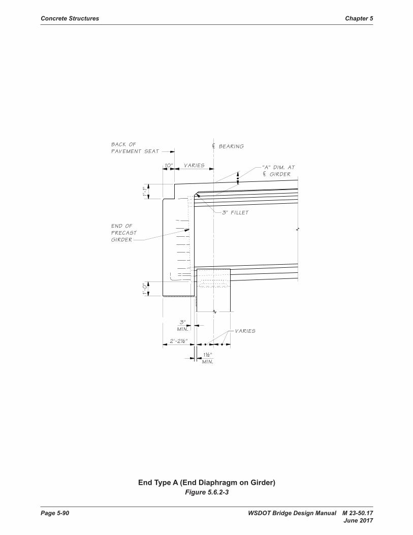
Page 5-90 WSDOT Bridge Design Manual M 23-50.17 June 2017
Concrete Structures Chapter 5
Chapter 5 Concrete Structures
WSDOT Bridge Design Manual M 23-50.04 Page 5.6-7 August 2010
E. Girder End Types
There are four end types shown on the standard girder sheets. Due to the extreme depth of the WF83G, WF95G and WF100G girders, and possible end of girder tilt at the piers for profile grades, the designer will need to pay particular attention to details to assure the girders will fit and perform as intended. The four end types are shown as follows:
1. End Type A
End Type A as shown in Figure 5.6.2-4 is for cantilever end piers with an end diaphragm cast on the end of the girders. End Type A has a recess at the bottom of the girder near the end for an elastomeric bearing pad. See Appendix 5.6-A7-9 and 5.6-A9-12 for bearing pad details. The recess at the centerline of bearing is 0.5″ deep. This recess is to be used for profile grades up to and including 4%. The recess is to be replaced by an embedded steel plate flush with the bottom of the girder for grades over 4%. A tapered bearing plate, with stops at the edges to contain the elastomeric pad, can be welded or bolted to the embedded plate to provide a level bearing surface.
Reinforcing bars and pretensioned strands project from the end of the girder. The designer shall assure that these bars and strands fit into the end diaphragm. Embedment of the girder end into the end diaphragm shall be a minimum of 3″ and a maximum of 6″. For girder ends where the tilt would exceed 6″ of embedment, the girder ends shall be tilted to attain a plumb surface when the girder is erected to the profile grade.
The gap between the end diaphragm and the stem wall shall be a minimum of 1½″ or ½″ greater than required for longitudinal bridge movement.
1½"MIN.
¢ BEARING
2'-2½"
1'-0
"BACK OFPAVEMENT SEAT
10" VARIES "A" DIM. AT¢ GIRDER
1'-1"
3"MIN.
END OFPRECASTGIRDER
VARIES
3" FILLET
End Type A (End Diaphragm on Girder)Figure 5.6.2-4
End Type A (End Diaphragm on Girder)Figure 5.6.2-3
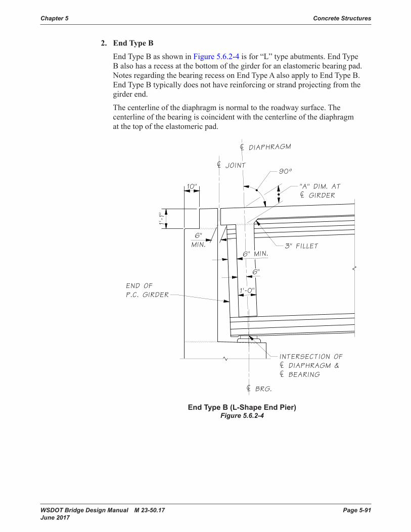
WSDOT Bridge Design Manual M 23-50.17 Page 5-91 June 2017
Chapter 5 Concrete Structures
2. End Type B
End Type B as shown in Figure 5.6.2-4isfor“L”typeabutments.EndTypeBalsohasarecessatthebottomofthegirderforanelastomericbearingpad.NotesregardingthebearingrecessonEndTypeAalsoapplytoEndTypeB.End Type B typically does not have reinforcing or strand projecting from the girder end.
The centerline of the diaphragm is normal to the roadway surface. The centerlineofthebearingiscoincidentwiththecenterlineofthediaphragmat the top of the elastomeric pad.
10"
1'-1"
¢ DIAPHRAGM
¢ JOINT
¢ BRG.
INTERSECTION OF¢ DIAPHRAGM &¢ BEARING
"A" DIM. AT¢ GIRDER
END OFP.C. GIRDER
3" FILLET
90°
6"MIN.
1'-0"
6" MIN.
6"
End Type B (L-Shape End Pier)Figure 5.6.2-4
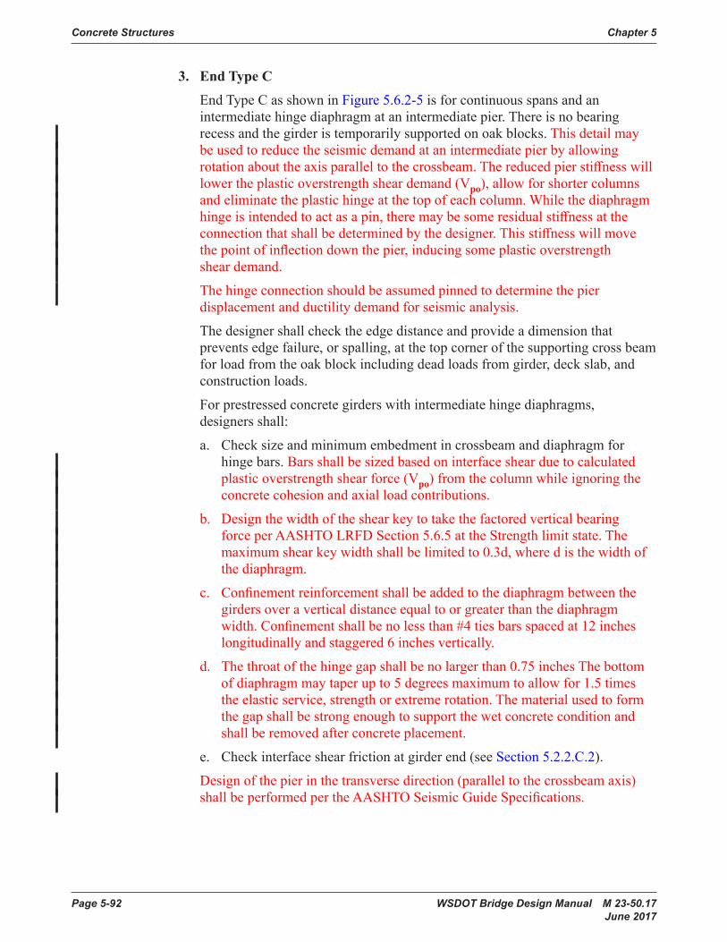
Page 5-92 WSDOT Bridge Design Manual M 23-50.17 June 2017
Concrete Structures Chapter 5
3. End Type C
End Type C as shown in Figure 5.6.2-5 is for continuous spans and an intermediatehingediaphragmatanintermediatepier.Thereisnobearingrecessandthegirderistemporarilysupportedonoakblocks.This detail may beusedtoreducetheseismicdemandatanintermediatepierbyallowingrotationabouttheaxisparalleltothecrossbeam.Thereducedpierstiffnesswilllower the plastic overstrength shear demand (Vpo), allow for shorter columns and eliminate the plastic hinge at the top of each column. While the diaphragm hingeisintendedtoactasapin,theremaybesomeresidualstiffnessattheconnectionthatshallbedeterminedbythedesigner.Thisstiffnesswillmovethepointofinflectiondownthepier,inducingsomeplasticoverstrengthshear demand.
Thehingeconnectionshouldbeassumedpinnedtodeterminethepierdisplacement and ductility demand for seismic analysis.
The designer shall check the edge distance and provide a dimension that preventsedgefailure,orspalling,atthetopcornerofthesupportingcrossbeamforloadfromtheoakblockincludingdeadloadsfromgirder,deckslab,andconstruction loads.
For prestressed concrete girders with intermediate hinge diaphragms, designersshall:
a. Checksizeandminimumembedmentincrossbeamanddiaphragmforhingebars.Barsshallbesizedbasedoninterfaceshearduetocalculatedplastic overstrength shear force (Vpo) from the column while ignoring the concretecohesionandaxialloadcontributions.
b. Designthewidthoftheshearkeytotakethefactoredverticalbearingforce per AASHTO LRFD Section 5.6.5 at the Strength limit state. The maximumshearkeywidthshallbelimitedto0.3d,wheredisthewidthofthe diaphragm.
c. Confinementreinforcementshallbeaddedtothediaphragmbetweenthegirders over a vertical distance equal to or greater than the diaphragm width.Confinementshallbenolessthan#4tiesbarsspacedat12incheslongitudinally and staggered 6 inches vertically.
d. Thethroatofthehingegapshallbenolargerthan0.75inchesThebottomof diaphragm may taper up to 5 degrees maximum to allow for 1.5 times the elastic service, strength or extreme rotation. The material used to form thegapshallbestrongenoughtosupportthewetconcreteconditionandshallberemovedafterconcreteplacement.
e. Check interface shear friction at girder end (see Section 5.2.2.C.2).
Designofthepierinthetransversedirection(paralleltothecrossbeamaxis)shallbeperformedpertheAASHTOSeismicGuideSpecifications.
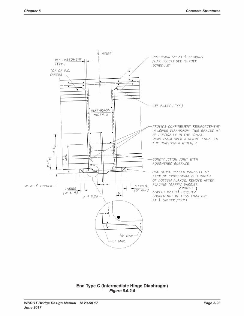
WSDOT Bridge Design Manual M 23-50.17 Page 5-93 June 2017
Chapter 5 Concrete Structures
VARIES(4" MIN.)
VARIES(3" MIN.)
6"
4" AT ¢ GIRDER
¢ HINGE
1'-0
"
1½" EMBEDMENT
(TYP.)
TOP OF P.C.GIRDER
DIMENSION "A" AT ¢ BEARING(OAK BLOCK) SEE "GIRDERSCHEDULE"
OAK BLOCK PLACED PARALLEL TOFACE OF CROSSBEAM, FULL WIDTHOF BOTTOM FLANGE. REMOVE AFTERPLACING TRAFFIC BARRIER.
ASPECT RATIOSHOULD NOT BE LESS THAN ONEAT ¢ GIRDER (TYP.)
WIDTHHEIGHT( )
45° FILLET (TYP.)
DIAPHRAGMWIDTH, d
d MIN.1.25 L
d
PROVIDE CONFINEMENT REINFORCEMENTIN LOWER DIAPHRAGM. TIES SPACED AT6" VERTICALLY IN THE LOWERDIAPHRAGM OVER A HEIGHT EQUAL TOTHE DIAPHRAGM WIDTH, d.
¾" GAP
5° MAX.
a • 0.3d
CONSTRUCTION JOINT WITHROUGHENED SURFACE
End Type C (Intermediate Hinge Diaphragm)Figure 5.6.2-5
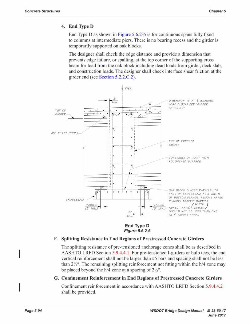
Page 5-94 WSDOT Bridge Design Manual M 23-50.17 June 2017
Concrete Structures Chapter 5
4. End Type D
End Type D as shown in Figure 5.6.2-6isforcontinuousspansfullyfixedtocolumnsatintermediatepiers.Thereisnobearingrecessandthegirderistemporarilysupportedonoakblocks.
The designer shall check the edge distance and provide a dimension that prevents edge failure, or spalling, at the top corner of the supporting cross beamforloadfromtheoakblockincludingdeadloadsfromgirder,deckslab,and construction loads. The designer shall check interface shear friction at the girder end (see Section 5.2.2.C.2).
VARIES(3" MIN.)
VARIES(3" MIN.)
6"MIN.
TOP OFGIRDER
CROSSBEAM
OAK BLOCK PLACED PARALLEL TOFACE OF CROSSBEAM, FULL WIDTHOF BOTTOM FLANGE. REMOVE AFTERPLACING TRAFFIC BARRIER.
ASPECT RATIOSHOULD NOT BE LESS THAN ONEAT ¢ GIRDER (TYP.)
WIDTHHEIGHT( )
END OF PRECASTGIRDER
DIMENSION "A" AT ¢ BEARING(OAK BLOCK) SEE "GIRDERSCHEDULE"
CONSTRUCTION JOINT WITHROUGHENED SURFACE
45° FILLET (TYP.)
¢ PIER
3"MIN.
End Type DFigure 5.6.2-6
F. Splitting Resistance in End Regions of Prestressed Concrete Girders
Thesplittingresistanceofpre-tensionedanchoragezonesshallbeasdescribedinAASHTO LRFD Section 5.9.4.4.1.Forpre-tensionedI-girdersorbulbtees,theendverticalreinforcementshallnotbelargerthan#5barsandspacingshallnotbelessthan2½″.Theremainingsplittingreinforcementnotfittingwithintheh/4zonemaybeplacedbeyondtheh/4zoneataspacingof2½″.
G. Confinement Reinforcement in End Regions of Prestressed Concrete Girders
ConfinementreinforcementinaccordancewithAASHTOLRFD Section 5.9.4.4.2 shallbeprovided.
WSDOT Bridge Design Manual M 23-50.17 Page 5-95 June 2017
Chapter 5 Concrete Structures
H. Girder Stirrups
ForgirderswithCIPdeckslabs,girderstirrupsshallbefieldbentoverthetopmatofreinforcementinthedeckslab.Anexceptionisgirderstirrupsforslabandwideflangethindeckgirderswhichshallbebentattheheightshowninthestandardgirder plans.
Girderstirrupsmaybeprebent,buttheextendedhookshallbewithinthecoreoftheslab(theinsideedgeofthehookshallterminateabovethebottommatdeckslabbars).
I. Section Properties
Grosssectionproperties(includingthegrossdeckareatransformedbythegirder/deckmodularratioifapplicable)shallbeusedfordesignofprecastconcretegirdersincludingprestresslosses,camber,andflexuralcapacity.Transformedsections(transformingreinforcementtoanequivalentconcretearea)maybeusedin special cases with the approval of the WSDOT Bridge Design Engineer.
5.6.3 Fabrication and HandlingA. Shop Plans
Fabricatorsofprestressedconcretegirdersarerequiredtosubmitshopplanswhichshowspecificdetailsforeachgirder.TheseshopplansarereviewedforconformancewiththeContractPlansandspecifications.
B. Special Problems for Fabricators
1. Strand Tensioning
Themethodselectedforstrandtensioningmayaffectthedesignofthegirders.Thestrandarrangementsshownintheofficestandardplansandincludedinthe PGSuper computer program are satisfactory for tensioning methods used byfabricatorsinthisstate.Harpedstrandsarenormallytensionedbypullingthemasstraightstrandstoapartialtension.Thestrandsarethendeflectedvertically as necessary to give the required harping angle and strand stress. In ordertoavoidovertensioningtheharpedstrandsbythisprocedure,theslopeofthestrandsislimitedtoamaximumof6:1for0.5″φstrandsand8:1for0.6″φ strands.Thestraightstrandsaretensionedbystraightjacking.
2. Hold Down Forces
Forces on the hold-down units are developed as the harped strands are raised. Thehold-downdeviceprovidedbythefabricatormustbeabletoholdthevertical component of the harping forces. Normally a two or more hold-down unitisrequired.Standardcommercialhold-downunitshavebeenpreapprovedfor use with particular strand groups.
3. Numbers of Strands
Sincetheprestressingbedsusedbythegirderfabricatorscancarryseveralgirdersinaline,itisdesirablethatgirdershavethesamenumberofstrandswherepractical.Thisallowsseveralgirderstobesetupandcastatonetime.
Forpre-tensionedconcretegirders,thenumberofpermanentprestressingstrands(straightandharped)shallbelimitedto100total0.6″φ strands.

Page 5-96 WSDOT Bridge Design Manual M 23-50.17 June 2017
Concrete Structures Chapter 5
C. Handling of Prestressed Concrete Girders
1. In-Plant Handling
ThemaximumweightthatcanbehandledbyprecastingplantsinthePacificNorthwest is 252 kips. Pre-tensioning lines are normally long enough so that the weight of a girder governs capacity, rather than its length. Headroom is also not generally a concern for the deeper sections.
2. Lateral Stability During Handling
Thedesignershallspecifytheliftingembedmentlocations(centroid 3′minimumfromends-seeStandard Specifications Section 6-02.3(25)L), maximummidspanverticaldeflection and the corresponding concrete strength at release that satisfiestheallowablestresscriteriafromSection5.2.1.Cand providesanadequatefactorofsafetyforlateralstability.ThecalculationsshallconformtomethodsasdescribedinStandard Specifications Section 6-02.3(25) and reference 26. Factors of safety of 1.0 against cracking and 1.5 against failureshallbeused.
Asaresultoftheassumedliftingembedmenttransverseplacementtoleranceandthegirdersweeptolerance,biaxialstressesduetolateralbendingoccuratthegirdertiltequilibriumcondition.AllowablestressesshallbeevaluatedforthegirdertiltequilibriumconditionforahanginggirderasdescribedinStandard Specifications Section 6-02.3(25) and reference 26.
Lateralstabilitycanbeaconcernwhenhandlinglong,slendergirders.Lateralbendingfailuresaresudden,catastrophic,costly,poseaseriousthreattoworkersandsurroundings,andthereforeshallbeconsideredbydesigners.When the girder forms are stripped from the girder, the prestressing level is higher and the concrete strength is lower than at any other point in the life of themember.Liftingembedment/supportmisalignment,horizontalgirdersweepand other girder imperfections can cause the girder to roll when handling, causingacomponentofthegirderweighttoberesistedbytheweakaxis.
Lateralstabilitymaybeimprovedusingthefollowingmethods:
a. Movetheliftingembedmentsawayfromtheends.Thismayincreasetherequiredconcretereleasestrength,becausedecreasingthedistancebetweenlifting devices increases the concrete stresses at the harp point. Stresses at the support may also govern, depending on the exit location of the harped strands.
b. Selectagirdersectionthatisrelativelywideandstiffaboutitsvertical(weak) axis.
c. Addtemporaryprestressinginthetopflange.
d. Brace the girder.
e. Raise the roll axis of the girder with a rigid yoke.

WSDOT Bridge Design Manual M 23-50.17 Page 5-97 June 2017
Chapter 5 Concrete Structures
D. Shipping Prestressed Concrete Girders
1. General
Theabilitytoshipgirderscanbeinfluencedbyalargenumberofvariables,includingmodeoftransportation,weight,length,height,andlateralstability.Theabilitytoshipgirdersisalsostronglysite-dependent.Forlargeorheavygirders,routestothesiteshallbeinvestigatedduringthepreliminarydesignphase. To this end, on projects using large or heavy girders, WSDOT can place an advisory in their special provisions including shipping routes, estimated permit fees, escort vehicle requirements, Washington State Patrol requirements, and permit approval time.
2. Mode of Transportation
Threemodesoftransportationarecommonlyusedintheindustry:truck,rail,andbarge.InWashingtonState,anoverwhelmingpercentageofgirdersaretransportedbytruck,sodiscussioninsubsequentsectionswillbeconfinedtothismode.However,onspecificprojects,itmaybeappropriatetoconsiderrailorbargetransportation.
Standard rail cars can usually accommodate larger loads than a standard truck. Rail cars range in capacity from approximately 120 to 200 kips. However, unlesstherailsystemrunsdirectlyfromtheprecastingplanttothejobsite,membersmustbetruckedforatleastsomeoftheroute,andweightmayberestrictedbythetruckinglimitations.
Foraprojectwherealargenumberofgirdersarerequired,bargetransportationis usually the most economical. Product weights and dimensions are generally notlimitedbybargedelivery,butbythehandlingequipmentoneitherend.Inmostcases,ifaproductcanbemadeandhandledintheplant,itcanbeshippedbybarge.
3. Weight Limitations
ThenetweightlimitationwithtruckingequipmentcurrentlyavailableinWashingtonStateisapproximately190kips,ifareasonabledeliveryrate(numberofpiecesperday)istobemaintained.Productweightsofupto252kipscanbehauledwithcurrentlyavailableequipmentatalimitedrate.
Longspanprestressedconcretegirdersmaybearincreasedcostsduetodifficultiesencounteredduringfabrication,shipping,anderection.Generally,costswillbelessifagirdercanbeshippedtotheprojectsiteinonepiece.However, providing an alternate spliced-girder design to long span one-piece pre-tensionedgirdersmayreducethecostthroughcompetitivebidding.
When a spliced prestressed concrete girder alternative is presented in the Plans, thesubstructureshallbedesignedanddetailedforthemaximumforceeffectcaseonly(noalternativedesignforsubstructure).
Localcarriersshouldbeconsultedonthefeasibilityofshippinglargeorheavygirdersonspecificprojects.
Page 5-98 WSDOT Bridge Design Manual M 23-50.17 June 2017
Concrete Structures Chapter 5
4. Support Locations
The designer shall provide shipping support locations in the plans to ensure adequategirderstability.Shippingsupportlocationsshallbenocloserthanthegirder depth to the ends of the girder at the girder centerline. The overhangs at theleadingandtrailingendsofthegirdersshouldbeminimizedandequalifpossible.Generally,theleadingendoverhangshouldnotexceed15′toavoidinterferencewithtruckingequipment.Localcarriersshouldbeconsultedifa larger leading end overhang is required. Shipping support locations shall maintaintheconcretestresseswithinallowablelimits.
Lengthbetweenshippingsupportlocationsmaybegovernedbyturningradiiontheroutetothejobsite.Potentialproblemscanbecircumventedbymovingthesupportpointsclosertogether(awayfromtheendsofthegirder),orbyselectingalternateroutes.Upto130′betweensupportsistypicallyacceptablefor most projects.
5. Height Limitations
Theheightofadeepgirdersectionsittingonajeepandsteerabletrailerisofconcernwhenconsideringoverheadobstructionsontheroutetothejobsite.Theheightofthesupportisapproximately6′abovetheroadwaysurface.Whenaddingthedepthofthegirder,includingcamber,theoverallheightfromtheroadwaysurfacetothetopofconcretecanrapidlyapproach14′.Overheadobstructionsalongtherouteshouldbeinvestigatedforadequateclearanceinthepreliminarydesignphase.Obstructionswithoutadequateclearancemustbebypassedbyselectingalternateroutes.
Expectations are that, in some cases, overhead clearance will not accommodate the vertical stirrup projection on deeper WSDOT standard girder sections. Alternatestirrupconfigurationscanbeusedtoattainadequateclearance,dependingontheroutefromtheplanttothejobsite.
6. Lateral Stability During Shipping
The designer shall specify concrete strengths, shipping support locations, minimum shipping support rotational spring constants, shipping support center-to-center wheel spacing, maximummidspanverticaldeflections and temporary topstrandconfigurationsinthePlansthatsatisfytheallowablestresscriteriafrom Section 5.2.1.C and provideadequatefactorsofsafetyforlateralstabilityduring shipping. The calculations shall conform to methods describedinStandard Specifications Section 6-02.3(25) and reference 26. Factors of safety of 1.0 against cracking and 1.5 against failure androllovershallbeused.Seethediscussionaboveonlateralstabilityduringhandlingofprestressedconcretegirdersforsuggestionsonimprovingstability.
Therotationalstiffnessandcenter-to-centerwheelspacingusedindesignshallbetakenfromTable5.6.3-1. Design the girder for transportation with the least stiffsupportsystemaspossiblewhileachievingrecommendedfactorsofsafety.

WSDOT Bridge Design Manual M 23-50.17 Page 5-99 June 2017
Chapter 5 Concrete Structures
Shipping Support Rotational Spring Constant, Kθ (Kip-in/radian)
Shipping Support Center-to-Center Wheel Spacing, Wcc
40,000 7250,000 7260,000 72 or 9670,000 9680,000 96
Shipping Support ParametersTable 5.6.3-1
E. Erection
A variety of methods are used to erect prestressed concrete girders, depending on theweight,length,availablecranecapacity,andsiteaccess.Liftinggirdersduringerection is not as critical as when they are stripped from the forms, particularly whenthesameliftingdevicesareusedforboth.However,ifaseparatesetoferectiondevicesareused,thegirdershallbecheckedforstressesandlateralstability.Inaddition,oncethegirderissetinplace,thefreespanbetweensupportsisusuallyincreased.Windcanalsoposeaproblem.Consequently,whengirdersareerected,theyshallimmediatelybebraced.Thetemporarybracingofthegirdersisthecontractor’sresponsibility.
F. Construction Sequence for Multi-Span Prestressed Concrete Girder Bridges
Formulti-spanprestressedconcretegirderbridges,thesequenceandtimingofthesuperstructureconstructionhasasignificantimpactontheperformanceanddurabilityofthebridge.Inordertomaximizetheperformanceanddurability,the “construction sequence” details shown on the Bridge Standard Drawings website(www.wsdot.wa.gov/Bridge/Structures/StandardDrawings.htm) shall befollowedforallnewWSDOTmulti-spanprestressedconcretegirderbridges.Particularattentionshallbepaidtothetimingofcastingthelowerportionofthepierdiaphragms/crossbeams(30daysminimumaftergirderfabrication)andtheupperportionofthediaphragms/crossbeams(10daysminimumafterplacementofthedeckslab).Therequirementsapplytomulti-spanprestressedconcretegirderbridgeswithmonolithicandhingediaphragms/crossbeams.
5.6.4 Superstructure OptimizationA. Girder Selection
Cost of the girders is a major portion of the cost of prestressed concrete girder bridges.Muchcareisthereforewarrantedintheselectionofgirdersandinoptimizing their position within the structure. The following general guidelines shouldbeconsidered.
1. Girder Series Selection
AllgirdersinabridgeshallbeofthesameseriesunlessapprovedotherwisebytheBridgeandStructuresEngineer.Ifverticalclearanceisnoproblem,alargergirderseries,utilizingfewergirderlines,maybeadesirablesolution.
Fewergirderlinesmayresultinextrareinforcementandconcretebutlessformingcost.Theseitemsmustalsobeconsidered.

Page 5-100 WSDOT Bridge Design Manual M 23-50.17 June 2017
Concrete Structures Chapter 5
2. Girder Concrete Strength
Highergirderconcretestrengthsshouldbespecifiedwherethatstrengthcanbeeffectivelyusedtoreducethenumberofgirderlines,seeSection 5.1.1.A.2. Whenthebridgeconsistsofalargenumberofspans,considerationshouldbegiventousingamoreexactanalysisthantheusualdesignprograminanattempttoreducethenumberofgirderlines.Thisanalysisshalltakeintoaccount actual live load, creep, and shrinkage stresses in the girders.
3. Girder Spacing
Considerationmustbegiventothedeckslabcantileverlengthtodeterminethemost economical girder spacing. This matter is discussed in Section 5.6.4.B. Thedeckslabcantileverlengthshouldbemadeamaximumifalineofgirderscanbesaved.Itisrecommendedthattheoverhanglength,fromedgeofslabtocenterlineofexteriorgirder,belessthan40percentofgirderspacing;then the exterior girder can use the same design as that of the interior girder. The following guidance is suggested.
i. Tapered Spans
Ontaperedroadways,theminimumnumberofgirderlinesshouldbedeterminedasifallgirderspacesweretobeequallyflared.Asmanygirdersaspossible,withinthelimitationsofgirdercapacityshouldbeplaced.Deckslabthicknessmayhavetobeincreasedinsomelocationsinorderto accomplish this.
ii. Curved Spans
Oncurvedroadways,normallyallgirderswillbeparalleltoeachother.It is critical that the exterior girders are positioned properly in this case, asdescribedinSection 5.6.4.B.
iii. Geometrically Complex Spans
Spanswhicharecombinationsoftaperandcurveswillrequireespeciallycarefulconsiderationinordertodevelopthemosteffectiveandeconomicalgirderarrangement.Wherepossible,girderlengthsandnumbersofstraightandharpedstrandsshouldbemadethesameforasmanygirdersaspossiblein each span.
iv. Number of Girders in a Span
Usuallyallspanswillhavethesamenumberofgirders.Whereaestheticsoftheundersideofthebridgeisnotafactorandwhereagirdercanbesavedinashortsidespan,considerationshouldbegiventousingunequalnumbersofgirders.Itshouldbenotedthatthiswillcomplicatecrossbeamdesignbyintroducingtorsioneffectsandthatadditionalreinforcementwillberequiredinthecrossbeam.
WSDOT Bridge Design Manual M 23-50.17 Page 5-101 June 2017
Chapter 5 Concrete Structures
B. Bridge Deck Cantilevers
Theexteriorgirderlocationisestablishedbysettingthedimensionfromcenterlineoftheexteriorgirdertotheadjacentcurbline.Forstraightbridgesthisdimensionwillnormallybenolessthan2′-6″forW42G,W50G,andW58G;3′-0″forW74G;and3′-6″forWF74G,WF83G,WF95GandWF100G.Someconsiderationswhichaffectthisarenotedbelow.
1. Appearance
Normally,forbestappearance,thelargestbridgedeckoverhangwhichispracticalshouldbeused.
2. Economy
Fortunately,theconditiontendingtowardbestappearanceisalsothatwhichwillnormallygivemaximumeconomy.Largercurbdistancesmaymeanthatalineofgirderscanbeeliminated,especiallywhencombinedwithhighergirderconcrete strengths.
3. Bridge Deck Strength
Itmustbenotedthatforlargeroverhangs,thebridgedecksectionbetweentheexteriorandthefirstinteriorgirdermaybecriticalandmayrequirethickening.
4. Drainage
Wheredrainageforthebridgeisrequired,waterfrombridgedrainsisnormallypiped across the top of the girder and dropped inside of the exterior girder line. Alargebridgedeckcantileverlengthmayseverelyaffectthisarrangementanditmustbeconsideredwhendeterminingexteriorgirderlocation.
5. Bridge Curvature
When straight prestressed concrete girders are used to support curved roadways,thecurbdistancemustvary.Normally,themaximumbridgedeckoverhangatthecenterlineofthelongspanwillbemadeapproximatelyequalto the overhang at the piers on the inside of the curve. At the point of minimum curbdistance,however,theedgeofthegirdertopflangeshouldbenocloserthan1′-0″fromthebridgedeckedge.Wherecurvatureisextreme,othertypesofbridgesshouldbeconsidered.Straightgirderbridgesonhighlycurvedalignmentshaveapoorappearanceandalsotendtobecomestructurallylessefficient.
C. Diaphragm Requirements
1. General
Diaphragmsusedwithprestressedconcretegirderbridgesservemultiplepurposes. During the construction stage, the diaphragms help to provide girder stabilityforthebridgedeckplacement.Duringthelifeofthebridge,thediaphragmsactasloaddistributingelements,andareparticularlyadvantageousfordistributionoflargeoverloads.Diaphragmsalsoimprovethebridgeresistance to over-height impact loads.
Page 5-102 WSDOT Bridge Design Manual M 23-50.17 June 2017
Concrete Structures Chapter 5
Diaphragmsforprestressedconcretegirderbridgesshallbecast-in-placeconcrete.Standarddiaphragmsanddiaphragmspacingsaregivenintheofficestandardsforprestressedconcretegirderbridges.Forlargegirderspacingsorotherunusualconditions,specialdiaphragmdesignsshallbeperformed.
Insertsmaybeusedtoaccommodatetheconstructionofintermediatediaphragmsforconnectionsbetweenthediaphragmandthewebofprestressedconcrete girders. The designer shall investigate the adequacy of the insert and the connection to develop the tensile capacity of diaphragm reinforcement. The designer shall also investigate the interface shear capacity of the diaphragm-to-webconnectionsforconstructionanddeckplacementloads.
Openholesshouldbeprovidedforinteriorwebssoreinforcementcanbeplaced through.
2. Design
Diaphragmsshallbedesignedastransversebeamelementscarryingbothdeadloadandliveload.Wheelloadsfordesignshallbeplacedinpositionssoastodevelop maximum moments and maximum shears.
3. Geometry
Diaphragmsshallnormallybeorientedparalleltoskew(asopposedtonormaltogirdercenterlines).Thisprocedurehasthefollowingadvantages:
a. Thebuild-upofhigherstressesattheobtusecornersofaskewedspanisminimized.Thisbuild-uphasoftenbeenignoredindesign.
b. Skeweddiaphragmsareconnectedatpointsofapproximatelyequalgirderdeflectionsandthustendtodistributeloadtothegirdersinamannerthatmore closely meets design assumptions.
c. The diaphragms have more capacity as tension ties and compression struts are continuous. Relatively weak inserts are only required at the exterior girder.
Oncurvedbridges,diaphragmsshallnormallybeplacedonradiallines.
4. Full or Partial Depth Intermediate Diaphragms
Fulldepthintermediatediaphragmsasshownintheofficestandardplansshallbeusedforalldeckbulbteeandwideflangedeckgirdersuperstructures.
BasedonresearchdonebyWashingtonStateUniversity(WSU)ondamagebyover-height loads24, the use of intermediate diaphragms for I-shaped prestressed concretegirderbridgeswithCIPconcretebridgedecks(includingWF,wideflangethindeck,etc.)shallbeasfollows:
a. FulldepthintermediatediaphragmsasshownintheofficestandardplansshallbeusedforbridgescrossingoverroadsofADT>50000.
b. Eitherfulldepthorpartialdepthintermediatediaphragmsasshownintheofficestandardplansmaybeusedforallbridgesnotincludedinitem1.
Theuseoffullorpartialdepthintermediatediaphragmsinbridgewideningsshallbeconsideredonacase-by-casebasisdependingonthewidthofthewideningandnumberofaddedgirders.

WSDOT Bridge Design Manual M 23-50.17 Page 5-103 June 2017
Chapter 5 Concrete Structures
5. Tub Girder Intermediate Diaphragms
Intermediatediaphragmsshallbeprovidedbothinsideandbetweenprestressedconcretetubgirders.
Thediaphragmsinsidethetubmaybecastinthefieldoratthefabricationplant.Thebottomofthediaphragminsidethetubshallbeatleast3inchesabovethetopofthebottomflange.
Thediaphragmsbetweenthetubsshallbecastinthefield.Fordiaphragmsbetweenthetubs,theroughenedsurfaceorshearkeysontheslopedwebfacesmaynotbeeffectiveinresistinginterfaceshear.Alldiaphragmandconstructionloadsonthediaphragmbeforethedeckcuresandgainsstrengthwillthenberesistedbythereinforcementorinsertsalone.
D. Skew Effects
Skewinprestressedconcretegirderbridgesaffectsstructuralbehaviorandmemberanalysis and complicates construction.
1. Analysis
Normally,theeffectofskewongirderanalysisisignored.Itisassumedthatskewhaslittlestructuraleffectonnormalspansandnormalskews.Forshort,widespansandforextremeskews(valuesover30°),theeffectoftheskewonstructuralactionshallbeinvestigated.Alltrapezoidaltub,slab,wideflangedeck,wideflangethindeckanddeckbulb-teegirdershaveaskewrestrictionof 30°.
Skews at ends of prestressed concrete girders cause prestressing strand force transfertobeunbalancedaboutthegirdercenterlineatgirderends.Insomecases,thishascausedbottomflangecracking.RecentprojectswherethiscrackingoccurredareContract8128(BridgeNumber522/142NhasW74Ggirderswith55degreeskewand8bottomflangestraightstrands)andContract8670(BridgeNumber5/456EhasWF100Ggirderswith56degreeskewand40bottomflangestraightstrands).DetailsshowninFigure 5.6.4-1couldbeusedtominimizebottomflangecrackingforgirderswithlargeskews.

Page 5-104 WSDOT Bridge Design Manual M 23-50.17 June 2017
Concrete Structures Chapter 5
Chapter 5Concrete Structures
Skewed Girder End DetailsTo Prevent Cracking
Figure 5.6.4-1
A
3 S
PA.@
2" = 6
"
7 SPA @ 2"= 1'-2"
¢ GIRDER
7 SPA @ 2"= 1'-2"
4½"
BOTTOM FLANGE DEBONDED STRANDS
¢ G
IRDER
DEBONDING SHEATHING (TYP.)
DEBOND STRANDSAT SKEW
ALTERNATE GIRDER END DEBOND AND REINFORCEMENTABOUT GIRDER ¢ FOR OPPOSITE END
DEBONDED STRAND (TYP.)
SECTION A
(4) #5 x 6'-0
(2) #6 x 8'-0"
Skewed Girder End Details to Prevent CrackingFigure 5.6.4-1
2. Detailing
Tominimizelaborcostsandtoavoidstressproblemsinprestressedconcretegirderconstruction,theendsofgirdersforcontinuousspansshallnormallybemade skewed. Skewed ends of prestressed concrete girders shall always match the piers they rest on at either end.
E. Grade and Cross Slope Effects
Large cross slopes require an increased amount of the girder pad dimension (‘A’dimension)necessarytoensurethatthestructurecanbebuilt.Thiseffectisespeciallypronouncedifthebridgeisonahorizontalorverticalcurve.Caremustbetakenthatdeckdrainagedetailsreflectthecrossslopeeffect.
Girderlengthsshallbemodifiedforaddedlengthalonggradeslope.

WSDOT Bridge Design Manual M 23-50.17 Page 5-105 June 2017
Chapter 5 Concrete Structures
F. Curve Effect and Flare Effect
Curves and tapered roadways each tend to complicate the design of straight girders. The designer must determine what girder spacing to use for dead load and live load designandwhetherornotarefinedanalysis,thatconsidersactualloadapplication,iswarranted.Normally,thegirderspacingatcenterlineofspancanbeusedforgirder design, especially in view of the conservative assumptions made for the design of continuous girders.
G. Girder Pad Reinforcement
Girderswithalarge“A”dimensionmayrequireadeeppadbetweenthetopofthegirderandthebottomofthedeck.Whenthedepthofthepadatthecenterlineofthegirderexceeds6″,reinforcementshallbeprovidedinthepadasshowninFigure 5.6.4-2.
PAD HEIGHT
#4 AT MID-HEIGHTOF PAD (TYP.)
£#4 @ 1'-6"SPACING
CLEARANCE DETERMINED BYDECK PROTECTION SYSTEM
1" CLR. MIN.
¢ GIRDER
DECK REINFORCEMENT
1½" CLR.(TYP.)
GIRDER REINFORCEMENT
Girder Pad ReinforcementFigure 5.6.4-2
5.6.5 Repair of Damaged Prestressed Concrete Girders at FabricationWhengirderssufferdefectsduringfabricationordamagebeforebecomingpartofafinalstructure,thegirderrepairsshallbeaddressedwithpre-approvedrepairproceduresfromthecurrentAnnualPlantApprovaldocumentforthefabricator(seeStandard Specifications Section6-02.3(25)A).Iftherepairscannotbeaddressedbythisdocument,thefabricatorshallinitiatetheFaxResolutionprocessfromthecurrentAnnualPlantApprovaldocumenttoaddresscontractspecificrepairswiththeProjectOfficeandHQBridgeConstruction.Normally,nodesigneractionisrequired.Whenevaluating repairs for unusual situations not covered, the designer must ensure that therequiredstrengthandappearanceofthegirdercanbemaintained.Ifstressingwilloccuraftertherepairismade,normallynotestloadingisrequired;however,suchatestshouldbeconsidered.Seereference14 for guidance.

Page 5-106 WSDOT Bridge Design Manual M 23-50.17 June 2017
Concrete Structures Chapter 5
5.6.6 Repair of Damaged Prestressed Concrete Girders in Existing BridgesA. General
Thissectionisintendedtocoverrepairofdamagedgirdersonexistingbridges.Forrepair of newly constructed girders, see Section 5.6.5. Over-height loads are a fairly commonsourceofdamagetoprestressedconcretegirderbridges.Thedamagemayrangefromspallingandminorcrackingofthelowerflangeofthegirdertolossofamajorportionofagirdersection.Occasionally,oneormorestrandsmaybebroken.Thedamageismostofteninflictedontheexteriororfirstinteriorgirder.
B. Repair Procedure
The determination of the degree of damage to a prestressed concrete girder islargelyamatterofjudgment.Wheretheflangeareahasbeenreducedor strands lost, calculations can aid in making this judgment decision. The following are general categories of damage and suggested repair procedures (see references 15, 16).
1. Minor Damage
If the damage is slight and concerns only spalling of small areas of the outside surfaceoftheconcrete,repairmaybeaccomplishedbyreplacingdamagedconcreteareaswithconcretegrout.Theareawherenewconcreteistobeappliedshallfirstbethoroughlycleanedofloosematerial,dried,andthencoated with epoxy.
2. Moderate Damage
If damage is moderate, (damage does not exceed replacement criteria in Item 4 below),arepairprocedureshallbedevelopedusingthefollowingguidelines.Itisprobablethatsomeprestresswillhavebeenlostinthedamagedareadueto reduction in section and consequent strand shortening or through loss of strands.Thefollowingstepsshallbepartofanyproposedrepairprocedure:
i. Determine Condition
Sketch the remaining cross section of the girder and compute its reduced section properties. Determine the stress in the damaged girder due to the remaining prestress and loads in the damaged state. If severe overstresses arefound,actionmustbetakentorestrictloadsonthestructureuntiltherepairhasbeencompleted.IfthestrandlossissogreatthatAASHTOprestressrequirementscannotbemetwiththeremainingstrands,considerationshouldbegiventoreplacingthegirder.
ii. Restore Prestress If Needed
Prestressindamaged/severedstrandscansometimesberestoredwithmechanicalstrandcouplers.Damagedgirderswithbroken0.6”diameterstrandsmayneedtoberepairedwith0.5”diameterstrandsandadditionalpost-tensioningasneeded.Currentcommercially-availablecouplersarecapableofrestoringfullprestressingforceinstrandsofupto½”diameter.Verify that the restoration of full prestress force will not cause overstress in the damaged girder section.

WSDOT Bridge Design Manual M 23-50.17 Page 5-107 June 2017
Chapter 5 Concrete Structures
iii. Prepare a Repair Plan
Draw a sketch to show the area of concrete removal required for replacement of damaged concrete, and for installation of any mechanical strandcouplersrequired.Thedamagedareaistobethoroughlyprepared,coated with epoxy, and repaired with grout equal in strength to the original concrete.
3. Severe Damage
Wherethedamagetothegirderisconsideredtobeirreparableduetolossofmanystrands,extremecracking,etc.,thegirdershallbereplaced.Thishasbeendoneseveraltimes,butinvolvessomecareindeterminingaproperreplacement sequence.
Ingeneral,theprocedureconsistsofcuttingthroughtheexistingdeckslabanddiaphragms and removing the damaged girder. Adequate exposed reinforcement steelmustremaintoallowsplicingofthenewbars.Thenewgirderandnewreinforcement is placed and previously cut concrete surfaces are cleaned and coatedwithepoxy.Newdeckslabanddiaphragmportionsarethenpoured.
Itisimportantthatthecamberofthenewgirderbematchedwiththatintheoldgirders.Excessivecamberinthenewgirdercanresultininadequatedeckslabthickness.Girdercambercanbecontrolledbyprestress,curingtime,ordimensional changes.
Castingthenewbridgedeckanddiaphragmssimultaneouslyinordertoavoidoverloadingtheexistinggirdersinthestructureshouldbeconsidered.Extrabracingofthegirderatthetimeofcastingthebridgedeckwillberequired.
Methodsofconstructionshallbespecifiedintheplansthatwillminimizeinconvenienceanddangerstothepublicwhileachievingasatisfactorystructuralresult.Highearlystrengthgroutsandconcretesshouldbeconsidered.
In case of replacement of a damaged girder, the intermediate diaphragms adjacenttothedamagedgirdershallbereplacedwithfulldepthdiaphragmsas shown in Figure 5.6.6-1.
Incaseofreplacementofadamagedgirder,thereplacementgirdershouldbeof the same type or the same depth as the original damaged girder.
Incaseofrepairofadamagedgirderwithbrokenordamagedprestressingstrands,theoriginaldamagedstrandsshallbereplacedwithsimilardiameterstrands. Restoration of the prestress force as outlined in Section5.6.6B-2b shallbeconsidered.
Existingbridgeswithpigmentedsealershallhavereplacementgirderssealed.Thoseexistingbridgeswithoutpigmentedsealerneednotbesealed.

Page 5-108 WSDOT Bridge Design Manual M 23-50.17 June 2017
Concrete Structures Chapter 5Chapter 5Concrete Structures
#4 STIRRUP@ 1'-0" MAX.
¢ GIRDER
2 SPA.@ 3"
1'-6"
1½" MIN.6" MAX. THREAD
ANCHOR DETAILASTM A-307
1"ø BOLT (TYP.)
FACE OF WEB
2 ~ #7 FULL LENGTH
ALL GIRDERS WEBSSHALL BE VERTICAL
1" INSERT AND ANCHOR (TYP.).SEE "ANCHOR DETAIL"THIS SHEET
#7
3" MAX. 3" MAX.
2 ~ #4 BETWEENGIRDERS SPACEDAT 1'-0" MAX.(TYP.)
#7 FULL LENGTH
1'-0" MAX.
6"
#4 TIE (TYP.)
Full Depth Intermediate Diaphragm ReplacementFigure 5.6.6-1
4. Repair vs. Replacement of Damaged Girder
Severalfactorsneedtobeconsideredwhenevaluatingwhethertorepairorto replace a damaged girder. Among them are the level of concrete damage, numberofbrokenstrands,locationandmagnitudeofwebdamage,permanentoffsetoftheoriginalgirderalignment,andoverallstructuralintegrity.Otherconsiderations include fresh damage to previously damaged girders, damage to adjacent girders, and cost of repair versus replacement. Ultimately, the
WSDOT Bridge Design Manual M 23-50.17 Page 5-109 June 2017
Chapter 5 Concrete Structures
evaluationhingesonwhetherthegirdercanberestoredtoitsoriginalcapacityandwhetherthegirdercanberepairedsufficientlytocarryitsshareoftheoriginal load.
Thefollowingguidelinesdescribedamagedgirderconditionswhichrequirereplacement:• Strand Damage – More than 25 percent of prestressing strands are damaged/severed.Ifover25percentofthestrandshavebeensevered,replacement is required. Splicing is routinely done to repair severed strands. However,therearepracticallimitsastothenumberofcouplersthatcanbeinstalledinthedamagedarea.
• Girder Displacements–Thebottomflangeisdisplacedfromthehorizontalpositionmorethan½″per10′ofgirderlength.Ifthealignmentofthegirderhasbeenpermanentlyalteredbytheimpact,replacementisrequired.Examplesofnon-repairablegirderdisplacementincludecracksattheweb/flangeinterfacethatremainopen.Abruptlateraloffsetsmayindicatethatstirrupshaveyielded.Agirderthatispermanentlyoffsetmaynotberestorabletoitsoriginalgeometrictolerancebypracticalandcost-effectivemeans.
• Concrete Damage at Harping Point – Concrete damage at harping point resulting in permanent loss of prestress. Extreme cracking or major loss of concrete near the harping point may indicate a change in strand geometry and loss in prestress force. Such loss of prestress force in the existing damagedgirdercannotberestoredbypracticalandcosteffectivemeans,and requires girder replacement.
• Concrete Damage at Girder Ends – Severe concrete damage at girder ends resulting in permanent loss of prestress or loss of shear capacity. Extreme cracking or major loss of concrete near the end of a girder may indicateunbondingofstrandsandlossinprestressforceoralossofshearcapacity. Such loss of prestress force or shear capacity in the existing damagedgirdercannotberestoredbypracticalandcost-effectivemeans,and requires girder replacement.
• Significant Concrete Loss from the Web–Significantdamageofconcreteinthewebthatresultsinlossofshearcapacityshallrequiregirderreplacement.Thewebdamageshallbeconsideredsignificantwhenmorethan25percentofwebsectionisdamagedorwhenshearreinforcementhas yielded.
DamagedgirdersshallbereplacedinaccordancewithcurrentWSDOTdesigncriteria and with current girder series.
Thereareothersituationsaslistedbelowwhichdonotautomaticallytriggerreplacement,butrequirefurtherconsiderationandanalysis.• Significant Concrete Loss from the Bottom Flange – For girder damage involvingsignificantlossofconcretefromthebottomflange,considerationshouldbegiventoverifyingthelevelofstressremainingintheexposedprestressingstrands.Residualstrandstressvalueswillberequiredforanysubsequentrepairprocedures.

Page 5-110 WSDOT Bridge Design Manual M 23-50.17 June 2017
Concrete Structures Chapter 5
• Adjacent Girders – Capacity of adjacent undamaged girders. Considerationmustbegivenastowhetherdeadloadfromthedamagedgirderhasbeenshedtotheadjacentgirdersandwhethertheadjacentgirders can accommodate the additional load.
• Previously Damaged Girders – Damage to a previously damaged girder. Animpacttoagirderthathasbeenpreviouslyrepairedmaynotbeabletoberestoredtosufficientcapacity.
• Cost–Costofrepairversusreplacement.Replacementmaybewarrantedif the cost of repair reaches 70 percent of the replacement project cost.
• Continuous Girders – Continuous girders with or without raised crossbeamthatrequiressupportingfalseworkintheadjacentspans.
• Superstructure Replacement – Superstructure replacement shall beconsideredifmorethat50percentofallgirdersinthespanaredamagedor if there is a high risk of future impacts from over-height loads.
C. Miscellaneous References
ThegirderreplacementcontractsandsimilarjobslistedinTable5.6.6-1 should beusedforguidance:
Contract Project NameBridge
NumberTotal Bridge Length (ft)
Year work planned Work Description
7646 I-5 SR 11 Interchange Chuckanut Overcrossing Bridge
11/1 287 2009 Replace damaged PCG
8133 US 395 Court Street Bridge – Replace / Repair Girders
395/103 114 2011 Replace damaged PCG
8251 I-5 113th Ave SW Bridge Special Repair
5/309 204 2012 Replace damaged PCG
8220 SR 16 Olympic Drive NW Bridge Special Repair
16/120 207 2012 Replace damaged PCG
8218 SR 167 24th St . E Bridge Special Repair
167/38 382 2012 Replace damaged PCG
8489 I-5 Chamber Way Bridge Special Repair
5/227 185 2014 Replace damaged PCG
8598 SR 16 Olympic Drive NW Bridge Special Repair
16/120 207 2014 Replace damaged PCG
8801 I-5 NBCD Over 41st Division Dr . Special Repair
5/411NCD 172 2015 Replace damaged PCG
8810 I-5 Birch Bay Lynden Rd Bridge Bridge Repair
5/834 272 2015 Replace damaged PCG
8813 I-90, Front St Bridge 90/66S Girder Replacement
90/66S 231 2015 Replace damaged PCG
8828 I-90 Stampede Pass Interchange – Bridge Repair
90/113 151 2016 Replace damaged PCG span
Girder Replacement ContractsTable 5.6.6-1

WSDOT Bridge Design Manual M 23-50.17 Page 5-111 June 2017
Chapter 5 Concrete Structures
5.6.7 Deck GirdersA. General
Theterm“deckgirder”referstoagirderwhosetopflangeorsurfaceisthedrivingsurface,withorwithoutanoverlay.Theyincludeslab,double-tee,ribbed,deckbulb-tee,wideflangedeckandwideflangethindeckgirders.
Deck girders without a composite CIP concrete deck shall have a minimum concretecoverof2″overthetopmat.Thetopmatofreinforcementinthedeckgirder(topflange)shallbeepoxy-coated.
B. Slab Girders
Slabgirderspansbetweencenterlinebearingsshallbelimitedtotheprestressedconcretegirderheightmultipliedby30duetounexpectedvariationsfromtraditionalbeamcambercalculations.
Standardconfigurationsofslabgirdersareshowninthegirderstandardplans.Thewidthofslabgirdersshouldnotexceed8′-0″.
Aminimum5″compositeCIPbridgedeckshallbeplacedoverslabgirders.TheCIPconcretedeckshallataminimumbeClass4000Dconcretewithonelayerof#5epoxycoatedreinforcementinboththetransverseandlongitudinaldirections.Thelongitudinalreinforcementshallbespacedat12inchesmaximumandthetransversereinforcementshallbespacedat6inchesmaximum.
The AASHTO LRFD criteriafordeflectionshallbesatisfiedforslabgirders.
Aminimumoftwopermanenttopstrandsshallbeprovidedforslabgirders,oneadjacenttoeachedge.Additionalpermanenttopstrandscanbeusedifrequiredtocontrol girder end tensile stresses as well as concrete stresses due to plant handling, shipping and erection.
Insomecasesitmaybenecessarytousetemporarytopstrandstocontrolgirderend tensile stresses as well as concrete stresses due to plant handling, shipping anderection.Thesestrandsshallbebondedfor10′atbothendsofthegirder,andunbondedfortheremainderofthegirderlength.TemporarystrandsshallbecutpriortoequalizinggirdersandplacingtheCIPbridgedeck.Designersmayalsoconsiderothermethodstocontrolgirderstressesincludingdebondingpermanentstrands at girder ends and adding mild steel reinforcement.
Thespecifieddesigncompressivestrength(ƒ′c)ofslabgirdersshouldbekeptlessthanorequalto8ksitoallowmorefabricatorstobid.
Girder equalization, shear keys and weld ties are not required when a minimum 5″compositeCIPbridgedeckisplacedoverslabgirders.DifferentialcamberisexpectedtobesmallbutthedesignershouldensureitcanbeaccommodatedbytheCIP deck.
Designersshouldensurethatthecrossslopeofgirdersupportsarethesameatbothendsofeachgirderinordertopreventgirdertorsion,pointloads,andgapsbetweenthegirderandthebearings.
LateralrestraintofslabgirdersuperstructureswithendtypeAatabutmentsshallbeprovidedbyexternalgirderstops,oneoneachsideofthebridge.

Page 5-112 WSDOT Bridge Design Manual M 23-50.17 June 2017
Concrete Structures Chapter 5
C. Double-Tee and Ribbed Deck Girders
Double-teeandribbeddeckgirdersshallbelimitedtowideningexistingsimilarstructures.Anhotmixasphalt(HMA)overlaywithmembraneshallbespecified.Thesesectionsarecapableofspanningupto60′.
D. Deck Bulb-Tee Girders
Deckbulb-teegirdershavestandardgirderdepthsof35,41,53,and65inches.Thetopflange/deckmayvaryfrom4-feet1-inchto6-feetwide.Theyarecapableofspanningupto155feet.Deckbulb-teegirdersshallbelimitedtopedestrianbridges,temporarybridgesandtowideningexistingsimilarstructures.
Deckbulb-teegirdersshallhaveanHMAorconcreteoverlay.AwaterproofingmembraneshallbeprovidedwithanHMAoverlay.
Deckbulb-teegirdersshallbeinstalledwithgirderwebsplumb.Bridgedecksuperelevationshallbeaccommodatedbyvaryingthetopflangethickness.Superelevationshouldbelimitedsothatliftingembedmentscanbelocatedatthecenter of gravity of the girder to prevent complications with lifting, hauling and erection.Useofdeckbulb-teegirdersshouldbeavoidedwhensuperelevationtransitions occur within the span.
Girdersizeandweightshallbeevaluatedforshippingandhaulingtotheproject site.
E. Wide Flange Deck Girders
Wideflangedeckgirdershavestandardgirderdepthsrangingfrom39inchesto103inches.Thetopflange/deckmayvaryfrom5-feetto8-feetwide.Theyarecapableofspanningupto195feetfora5-foottopflangewidthand165feetforan8-foottopflangewidth.Wideflangedeckgirdersshallbelimitedtopedestrianbridges,temporarybridgesandtowideningexistingsimilarstructures.
WideflangedeckgirdersshallhaveanHMAorconcreteoverlay.AwaterproofingmembraneshallbeprovidedwithanHMAoverlay.
Wideflangedeckgirdersshallbeinstalledwithgirderwebsplumb.Bridgedecksuperelevationshallbeaccommodatedbyvaryingthetopflangethickness.Superelevationshouldbelimitedsothatliftingembedmentscanbelocatedatthecenter of gravity of the girder to prevent complications with lifting, hauling and erection.Useofwideflangedeckgirdersshouldbeavoidedwhensuperelevationtransitions occur within the span.
Girdersizeandweightshallbeevaluatedforshippingandhaulingtotheproject site.
F. Wide Flange Thin Deck Girders
Wideflangethindeckgirdershavestandardgirderdepthsrangingfrom36inchesto100inches.Thetopflangemayvaryfrom5-feetto8-feetwide.Theyarecapableofspanningupto225feetfora5-foottopflangewidthand200feetforan8-foottopflangewidth.

WSDOT Bridge Design Manual M 23-50.17 Page 5-113 June 2017
Chapter 5 Concrete Structures
Wideflangethindeckgirdersshallhaveaminimum5″thickcompositeCIPbridgedeck.Weldedtiesandgroutedkeysatflangeedgesarenotrequired.TheCIPbridgedeckthicknessshallbecapableofaccommodatingexpectedgirdercambervariationsandtolerances.TransversereinforcementintheCIPbridgedeckshallbedesigned to resist live loads and superimposed dead loads. Additional transverse reinforcementmaybenecessaryovertheflangeedgejointstohelpcontrolconcretecrackingintheCIPbridgedeck.
Wideflangethindeckgirdersshallbeinstalledwithgirderwebsplumb.BridgedecksuperelevationshallbeaccommodatedbyvaryingtheCIPbridgedeckthickness.UseofwideflangethindeckgirdersshouldbeavoidedwithlargesuperelevationsinordertolimitCIPbridgedeckthickness.
Girdersizeandweightshallbeevaluatedforshippingandhaulingtotheproject site.
5.6.8 Prestressed Concrete Tub GirdersA. General
Prestressedconcretetubgirders(UandUFsections)areanoptionformoderatebridgespans.
Thestandardtubgirders(Usections)have4′-0″or5′-0″bottomflangewidthsandare4′-6″,5′-6″or6′-6″deep.A6″deeptopflangecanbeaddedtotubgirders(UFsections)toimprovestructuralefficiencyandtoaccommodateplacementofstay-in-place precast deck panels.
Drainholesshallbeprovidedatthelowpointofthetubgirdersatthecenterlineofthebottomflange.
B. Curved Tub Girders
Curvedtubgirdersmaybeconsideredforbridgeswithmoderatehorizontalradiuses.I-girdersmaynotbecurved.
Curvedtubgirderscaneitherbedesignedinonepieceorinsegmentsdependingonspanconfigurationsandshippinglimitations.Curvedtubgirdersarepost-tensionedatthefabricationplantandshippedtothejobsite.Additionaljobsitepost-tensioningmayberequiredifsegmentassemblyisnecessary,orifcontinuityover intermediate piers is desired. Closure joints at segment splices shall meet the requirements of Section 5.9.4.C.
Thefollowinglimitationsshallbeconsideredforcurvedtubgirders:
1. The overall width of curved segments for shipment shall not exceed 16 feet.
2. Thelocationoftheshippingsupportsshallbecarefullystudiedsothatthesegmentisstableduringshipping.Thedifferenceindeadloadreactionsoftheshipping supports within the same axle shall not exceed 5 percent.
3. Themaximumshippingweightofsegmentsmaybedifferentdependingonthesize of the segments. The shipping weight shall meet the legal axle load limits setbytheRCW,butinnocaseshallthemaximumshippingweightexceed275 kips.
Page 5-114 WSDOT Bridge Design Manual M 23-50.17 June 2017
Concrete Structures Chapter 5
4. Theminimumwebthicknessshallbe10″.Othercross-sectionaldimensionsofWSDOTstandardtubgirdersareapplicabletocurvedtubgirders.
5. EffectsofcurvedtendonsshallbeconsideredinaccordancewithSection 5.8.1.F.
6. Theclearspacingbetweenductsshallbe2″min.Theductdiametershallnotexceed4½″.
5.6.9 Prestressed Concrete Girder Checking RequirementA. Shearreinforcingsizeandspacingshallbedeterminedbythedesigner.
B. Determine lifting location and required concrete strength at release to provide adequatestabilityduringhandling.Generallytemporarystrandsprovideadditionalstabilityforliftingandtransportation,andreducethecamber.Lesscamberallowsfor less “A” dimension and concrete pad dead weight on the structure. Temporary strandsarecutafterthegirdersareerectedandbracedandbeforetheintermediatediaphragms are cast.
C. Due to the extreme depth of the WF83G, WF95G, and WF100G girders, and possibletiltatthepiersforprofilegrades,thedesignerwillneedtopayparticularattentiontodetailstoassurethegirderswillfitandperformasintended.
D. Checkedgedistanceofsupportingcrossbeam.
5.6.10 Review of Shop Plans for Pre-tensioned GirdersPretensioningshopdrawingsshallbereviewedbythedesigner.Shopdrawings,afterreviewbythedesigner,shallbestampedwiththeofficialsealandreturnedtothebridgeconstructionsupportoffice.Thereviewmustinclude:
A. Allprestressingstrandsshallbeof½″or0.6″diametergrade270lowrelaxationuncoated strands.
B. Numberofstrandspergirder.
C. Jackingstressesofstrandsshallnotexceed0.75ƒpu.
D. Strand placement patterns and harping points.
E. Temporarystrandpattern,bondedlength,locationandsizeofblockoutsfor cutting strands.
F. Procedureforcuttingtemporarystrandsandpatchingtheblockoutsshallbespecified.
G. Numberandlengthofextendedstrandsandrebarsatgirderends.
H. Locations of holes and shear keys for intermediate and end diaphragms.
I. Locationandsizeofbearingrecesses.
J. Saw tooth at girder ends.
K. Locationandsizeofliftingloopsorliftingbars.
L. All horizontal and vertical reinforcement.
M. Girder length and end skew.
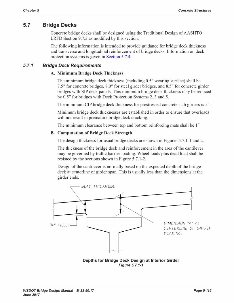
Chapter 5 Concrete Structures
WSDOT Bridge Design Manual M 23-50.17 Page 5-115 June 2017
5.7 Bridge DecksConcrete bridgedecksshallbedesignedusingtheTraditionalDesignofAASHTO LRFDSection9.7.3asmodifiedbythissection.
Thefollowinginformationisintendedtoprovideguidanceforbridgedeckthicknessandtransverseandlongitudinalreinforcementofbridgedecks.Informationondeckprotection systems is given in Section 5.7.4.
5.7.1 Bridge Deck RequirementsA. Minimum Bridge Deck Thickness
The minimum bridgedeck thickness (including 0.5″wearingsurface)shallbe7.5″forconcretebridges,8.0″forsteelgirderbridges,and8.5″ for concrete girder bridgeswithSIPdeckpanels.Thisminimumbridgedeckthicknessmaybereducedby0.5″forbridgeswithDeckProtectionSystems2, 3 and 5.
The minimum CIP bridge deck thickness for prestressed concreteslabgirdersis5″.
Minimumbridgedeckthicknesses areestablishedinordertoensurethatoverloadswillnotresultinprematurebridgedeckcracking.
Theminimumclearancebetweentopandbottomreinforcingmatsshallbe1″.
B. Computation of Bridge Deck Strength
The designthicknessforusualbridgedecksareshowninFigures 5.7.1-1 and 2.
Thethicknessofthebridgedeckandreinforcementintheareaofthecantilevermaybegovernedbytrafficbarrierloading.WheelloadsplusdeadloadshallberesistedbythesectionsshowninFigure5.7.1-2.
Designofthecantileverisnormallybasedontheexpecteddepthofthebridgedeck at centerline of girder span. This is usually less than the dimensions at the girder ends.
Depths for Bridge Deck Design at Interior Girder Figure 5.7.1-1

Concrete Structures Chapter 5
Page 5-116 WSDOT Bridge Design Manual M 23-50.17 June 2017
Depths for Bridge Deck Design at OverhangFigure 5.7.1-2
C. Computation of “A” Dimension
Thedistancefromthetopofthebridgedecktothetopofthegirderatcenterlinebearingatcenterlineofgirderisrepresentedbythe“A”Dimension.Itiscalculatedin accordance with the guidance of Appendix 5-B1. This ensures that adequate allowancewillbemadeforexcesscamber,transversedeckslopes,verticalandhorizontal curvatures. Where temporary prestress strands at top of girder are used to control the girder stresses due to shipping and handling, the “A” dimension must beadjustedaccordingly.
The note in the left margin of the layout sheet shallread:“A”Dimension=X”(notfor design).
5.7.2 Bridge Deck ReinforcementA. Transverse Reinforcement
Thesizeandspacingoftransversereinforcementmaybegovernedbyinteriorbridgedeckspandesignand cantilever design. Where cantilever design governs,shorthookedbarsmaybeaddedatthebridgedeckedgetoincreasethereinforcementavailableinthatarea.Toptransversereinforcementisalwayshookedatthebridgedeckedgeunlessatrafficbarrierisnotused.Toptransversereinforcementispreferablysplicedatsomepointbetweengirdersinordertoallowtheclearanceofthehookstothebridgedeckedgeformstobeproperlyadjustedinthefield.Usually,thebridgedeckedgehookswillneedtobetiltedinordertoplacethem.Onlargerbars,theclearanceforthelongitudinalbarthroughthehooksshall bechecked.Appendices5.3-A5through5.3-A8canbeusedtoaidinselectionofbarsizeandspacing.
Forskewedspans,thetransversebarsareplacednormaltobridgecenterlineandtheareasneartheexpansionjointsandbridgeendsarereinforcedbypartiallengthbars.Forraisedcrossbeambridges,thebottomtransversebridgedeckreinforcementisdiscontinuedatthecrossbeam.

Chapter 5 Concrete Structures
WSDOT Bridge Design Manual M 23-50.17 Page 5-117 June 2017
Thespacingofbarsoverthecrossbeammustbedetailedtobelarge enough to allowconcretetobepouredintothecrossbeam.Fortypicalrequirements,seeSection 5.3.3.D.
Forbridgedeckswithacrownedroadway,thebottomsurfaceandrebarshallbeflat,asshowninFigure5.7.2-1.
Bottom of Bridge Deck at Crown PointFigure 5.7.2-1
B. Longitudinal Reinforcement
This section discusses reinforcement requirements for resistance of longitudinal momentsincontinuousmulti-spanprestressedconcretegirderbridgesandislimitedtoreinforcementinthebridgedeck since capacity for resisting positive momentisprovidedbythegirderreinforcement.
1. Simple Spans
Forsimplespanbridges,longitudinalbridgedeckreinforcementisnotrequiredto resist negative moments and therefore the reinforcement requirements are nominal.Figure5.7.2-2defineslongitudinalreinforcementrequirementsforthesedecks.ThebottomlongitudinalreinforcementisdefinedbyAASHTOLRFDSection9.7.3.2requirementsfordistributionreinforcement.Thetoplongitudinalreinforcementisbasedoncurrentofficepractice.
Nominal Longitudinal Bridge Deck ReinforcementFigure 5.7.2-2
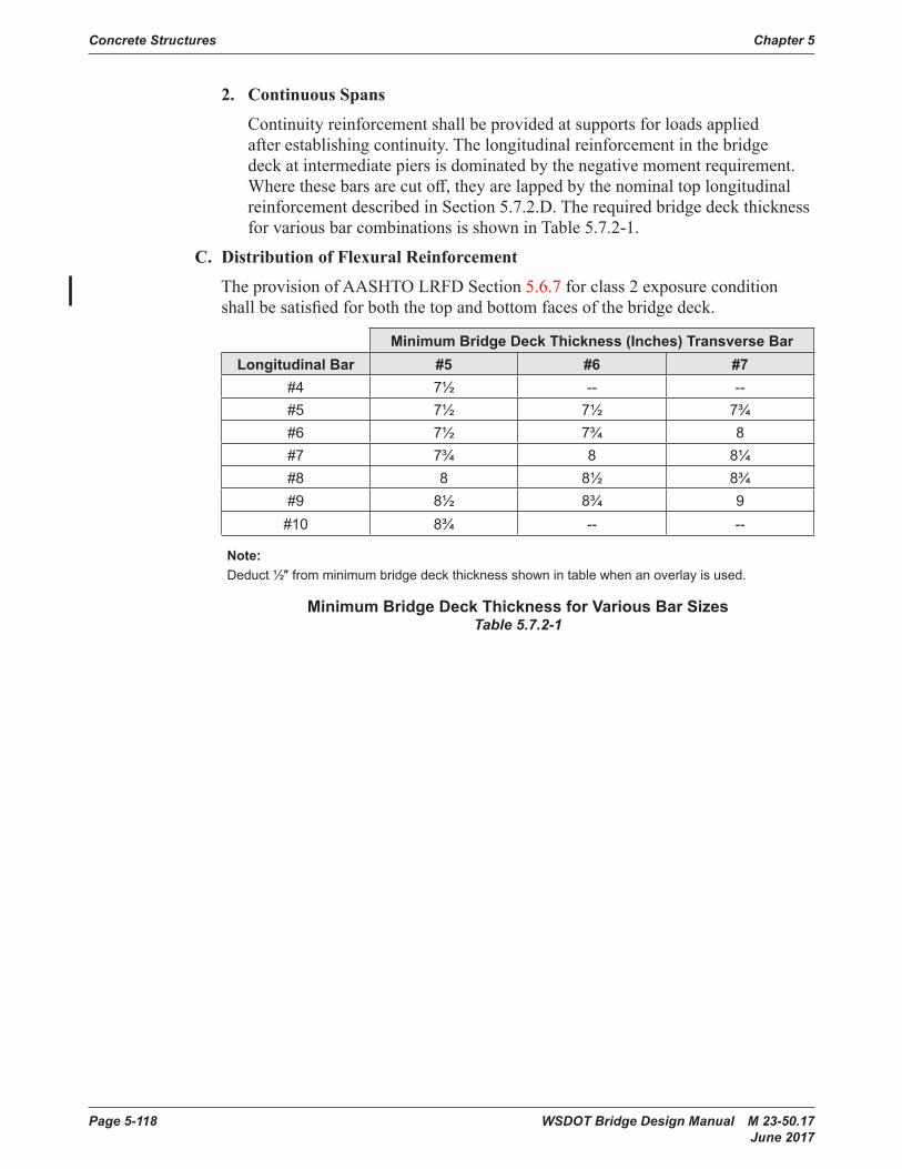
Concrete Structures Chapter 5
Page 5-118 WSDOT Bridge Design Manual M 23-50.17 June 2017
2. Continuous Spans
Continuityreinforcementshallbeprovidedatsupportsforloadsappliedafterestablishingcontinuity.Thelongitudinalreinforcementinthebridgedeckatintermediatepiersisdominatedbythenegativemomentrequirement.Wherethesebarsarecutoff,theyarelappedbythenominaltoplongitudinalreinforcementdescribedinSection 5.7.2.D. The required bridgedeckthicknessforvariousbarcombinationsisshowninTable5.7.2-1.
C. Distribution of Flexural Reinforcement
The provision of AASHTO LRFD Section 5.6.7 for class 2 exposure condition shallbesatisfiedforboththetopandbottomfacesofthebridgedeck.
Minimum Bridge Deck Thickness (Inches) Transverse BarLongitudinal Bar #5 #6 #7
#4 7½ -- --#5 7½ 7½ 7¾#6 7½ 7¾ 8#7 7¾ 8 8¼#8 8 8½ 8¾#9 8½ 8¾ 9
#10 8¾ -- --
Note:Deduct ½″ from minimum bridge deck thickness shown in table when an overlay is used.
Minimum Bridge Deck Thickness for Various Bar SizesTable 5.7.2-1
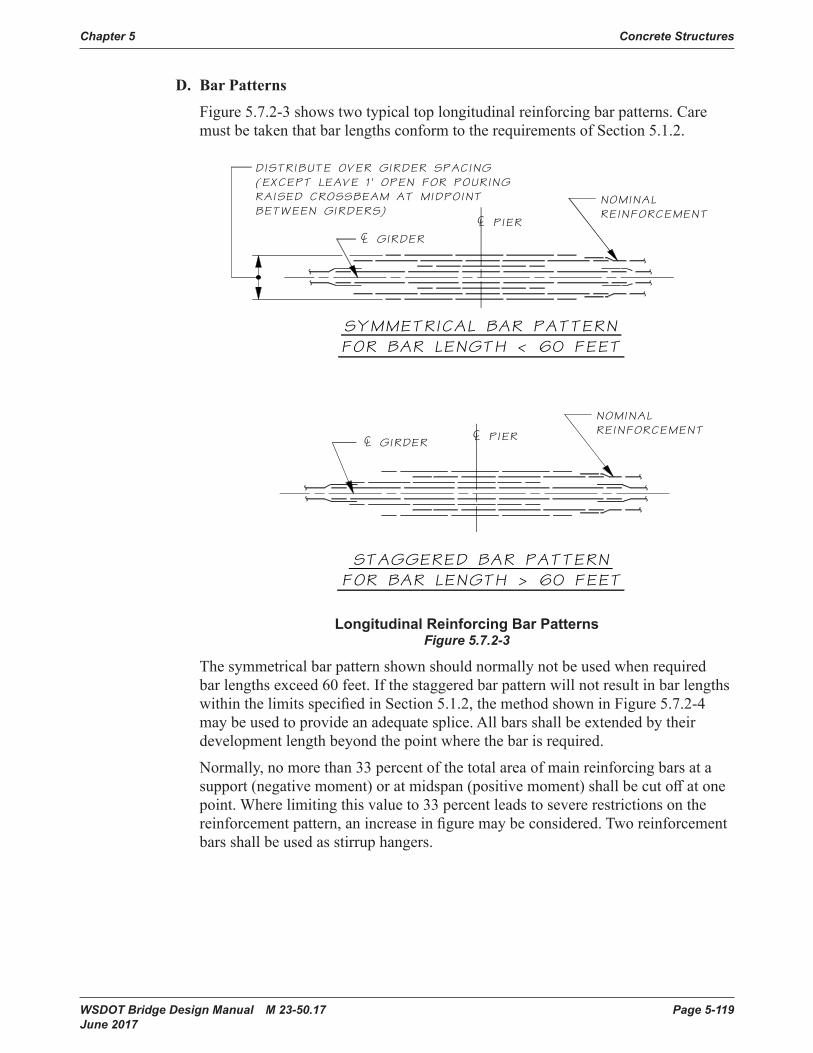
Chapter 5 Concrete Structures
WSDOT Bridge Design Manual M 23-50.17 Page 5-119 June 2017
D. Bar Patterns
Figure5.7.2-3showstwotypicaltoplongitudinalreinforcingbarpatterns.CaremustbetakenthatbarlengthsconformtotherequirementsofSection 5.1.2.
Longitudinal Reinforcing Bar PatternsFigure 5.7.2-3
Thesymmetricalbarpatternshownshouldnormallynotbeusedwhenrequiredbarlengthsexceed60feet.IfthestaggeredbarpatternwillnotresultinbarlengthswithinthelimitsspecifiedinSection 5.1.2, the method shown in Figure 5.7.2-4 maybeusedtoprovideanadequatesplice.Allbarsshallbeextendedbytheirdevelopmentlengthbeyondthepointwherethebarisrequired.
Normally, no more than 33 percent of the total area ofmainreinforcingbarsat a support (negative moment) or at midspan (positive moment)shallbecutoffatonepoint. Where limiting this value to 33 percent leads to severe restrictions on the reinforcementpattern,anincreaseinfiguremaybeconsidered.Tworeinforcementbarsshallbeused as stirrup hangers.
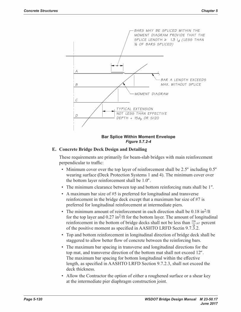
Concrete Structures Chapter 5
Page 5-120 WSDOT Bridge Design Manual M 23-50.17 June 2017
Bar Splice Within Moment EnvelopeFigure 5.7.2-4
E. Concrete Bridge Deck Design and Detailing
These requirementsareprimarilyforbeam-slabbridgeswithmainreinforcementperpendiculartotraffic:•Minimumcoveroverthetoplayerofreinforcementshallbe2.5″ including 0.5″
wearing surface (Deck Protection Systems 1 and 4). The minimum cover over thebottomlayerreinforcementshallbe1.0″.
• Theminimumclearancebetweentopandbottomreinforcingmatsshallbe1″.• A maximumbarsizeof#5ispreferredforlongitudinalandtransverse
reinforcement in the bridgedeckexceptthat amaximumbarsizeof#7is preferred for longitudinal reinforcement at intermediate piers.
•Theminimumamountofreinforcementineachdirectionshallbe0.18in2/ft for the top layer and 0.27 in2/ftforthebottomlayer.Theamountoflongitudinalreinforcementinthebottomofbridgedecksshallnotbelessthan220
√S≤67 percent
ofthepositivemomentasspecifiedinAASHTOLRFDSectin9.7.3.2.•Topandbottomreinforcementinlongitudinaldirectionofbridgedeckshallbestaggeredtoallowbetterflowofconcretebetweenthereinforcingbars.
•Themaximumbarspacingintransverseandlongitudinaldirectionsforthetopmat,andtransversedirectionofthebottommatshallnotexceed12″. Themaximumbarspacingforbottomlongitudinalwithintheeffectivelength,asspecifiedinAASHTOLRFD Section 9.7.2.3, shall not exceed the deck thickness.
• Allow the Contractor the option of either a roughened surface or a shear key at the intermediate pier diaphragm construction joint.

Chapter 5 Concrete Structures
WSDOT Bridge Design Manual M 23-50.17 Page 5-121 June 2017
•Both,topandbottomlayerreinforcementshallbeconsideredwhendesigningfor negative moment at the intermediate piers.
•Reducelapsplicesifpossible.Usestaggeredlapsplicesforbothtopandbottominlongitudinalandtransversedirections.
5.7.3 Stay-in-place Deck PanelsA. General
Theuseofprecast,prestressedstay-in-place(SIP)deckpanelsforbridgedecksmaybeinvestigatedatthepreliminarydesignstage.Theacceptanceevaluationwill consider such items as extra weight for seismic design and the resulting substructureimpacts.
The composite deck system consisting of precast prestressed concrete deck panels with a CIPtoppinghasadvantagesinminimizingtrafficdisruption,speedingupconstructionandsolvingconstructabilityissuesoncertainprojects.Contractors,inmostcases,preferthiscompositedeckpanelsystemforbridgedecksintrafficcongestedareasandotherspecificcases.
SIPdeckpanelsmaybeusedonWSDOTbridgeswith WSDOT Bridge and StructuresOfficeapproval.DetailsforSIPdeckpanelsareshownon the BridgeStandardDrawingswebsite(www.wsdot.wa.gov/Bridge/Structures/StandardDrawings.htm).
Steeldeckformsarenotpermittedinordertoallowinspectionofdecksoffitsandto avoid maintenance of a corrosion protection system.
B. Design Criteria
The design of SIP deck panels follows the AASHTO LRFD Bridge Design Specifications and the PCI Bridge Design Manual. The design philosophy of SIP deck panels is identical to simple span prestressed concrete girders. They are designed for Service Limit State and checked for Strength Limit State. The precast panels support the dead load of deck panels and CIP topping, and the composite SIP deck panel and CIP cross-section resists the live load and superimposed dead loads.ThetensilestressatthebottomofthepanelislimitedtozeroperWSDOTdesign practice.
C. Limitations on SIP Deck Panels
The conventional full-depth CIPbridgedeckshallbeusedformostapplications.However,theWSDOTBridgeandStructuresOfficemayallowtheuseofSIPdeckpanelswiththefollowinglimitations:
1. SIPdeckpanelsshallnotbeusedinnegative moment regions of continuous conventionallyreinforcedbridges.SIP deck panelsmaybeusedinpost-tensionedcontinuousbridges.
2. Bridge widening. SIP deck panelsarenotallowedinthebayadjacenttotheexistingstructurebecauseitisdifficulttosetthepanelsproperlyontheexistingstructure, and the requirement for a CIP closure. SIP deck panelscanbeusedon the other girders when the widening involves multiple girders.
Concrete Structures Chapter 5
Page 5-122 WSDOT Bridge Design Manual M 23-50.17 June 2017
3. Phased construction. SIP deck panelsarenotallowedinthebayadjacenttothepreviouslyplaceddeckbecauseoftherequirementfora CIP closure.
4. Prestressedconcretegirderswithnarrowflanges.PlacementofSIP deck panels ongirderswithflangeslessthan12″wideisdifficult.
5. Aminimumbridgedeck thickness of 8.5″, including 3.5″ precast deck panel and 5″ CIPconcretetoppingshallbespecified.
6. SIP deck panelsarenotallowedforsteelgirderbridges.
5.7.4 Bridge Deck ProtectionAllbridgedecks,precastorcast-in-placeslabs,ordeckgirderstructuresshalluseadeckprotectionsystemasdescribedinthissectiontoreducethedeteriorationofthebridgedeckandsuperstructure.TheWSDOTBridgeManagementUnitshalldetermine the type of protection system during the preliminary plan or Request For Proposal(RFP)stageforstructuresnotdescribedinthissection.Specialconditions(i.e.awidening)whereitmaybedesirabletodeviatefromthestandarddeckprotectionsystems require approval of the WSDOT Bridge Management Unit.
Preliminary plans shall indicate the protection system in the left margin in accordance with Section 2.3.8.
Sawcuttingorgrindingpavementitemsarenotallowedonthebridgedecks.Rumblestripsandrecessedpavementmarkersshallnotbeplacedonbridgedecks,orapproachslabsurfaceswhethertheyareconcreteorasphaltedasstatedinStandard Specifications Section 8-08 and 8-09, respectively.
Trafficdetectionloopsshallnotbelocatedinanexistingbridgesurface.Theymaybeinstalledduringtheconstructionofbridgedeckspriortoplacingthedeckconcreteinaccordance with Standard Plan J-50.16.
A. Deck Protection Systems
ThefollowingparagraphsdescribefiveWSDOTprotectivesystemsusedtoprotectaconcretebridgedeckdesign.
1. Type 1 Protection System
This is the minimum default protection system for cases where a protection systemhasnotbeenspecifiedonastructure.Type1protectionsystemshallbeusedforcast-in-placebridgedeckswithtwolayersofreinforcement,seeFigure 5.7.4-1.ThisalsoappliestoCIPslabbridges,deckreplacementsandthewideningofexistingdecks.System1consistsofthefollowing:
i. Aminimum2½″ofconcretecoverovertopbarofdeckreinforcing.Thecoverincludesa½″wearingsurfaceand¼″tolerancefortheplacement of the reinforcing steel.
ii. Boththetopandbottommatofdeckreinforcingshallbeepoxy-coated.
iii. Girder stirrups and horizontal shear reinforcement do not require epoxy-coating.
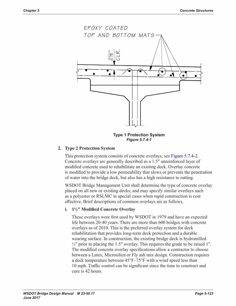
Chapter 5 Concrete Structures
WSDOT Bridge Design Manual M 23-50.17 Page 5-123 June 2017
Type 1 Protection SystemFigure 5.7.4-1
2. Type 2 Protection System
This protection system consists of concrete overlays, see Figure 5.7.4-2. Concreteoverlaysaregenerallydescribedasa1.5″unreinforcedlayerofmodifiedconcreteusedtorehabilitateanexistingdeck.Overlayconcreteismodifiedtoprovidealowpermeabilitythatslowsorpreventsthepenetrationofwaterintothebridgedeck,butalsohasahighresistancetorutting.
WSDOT Bridge Management Unit shall determine the type of concrete overlay placedonallneworexistingdecks;andmayspecifysimilaroverlayssuchas a polyester or RSLMC in special cases when rapid construction is cost effective.Briefdescriptionsofcommonoverlaysareasfollows.
i. 1½″ Modified Concrete Overlay
TheseoverlayswerefirstusedbyWSDOTin1979andhaveanexpectedlifebetween20-40years.Therearemorethan600bridgeswithconcreteoverlays as of 2010. This is the preferred overlay system for deck rehabilitationthatprovideslong-termdeckprotectionandadurablewearingsurface.Inconstruction,theexistingbridgedeckishydromilled½″priortoplacingthe1.5″overlay.Thisrequiresthegradetoberaised1″.ThemodifiedconcreteoverlayspecificationsallowacontractortochoosebetweenaLatex,MicrosilicaorFlyashmixdesign.Constructionrequiresadecktemperaturebetween45°F–75°Fwithawindspeedlessthan10mph.Trafficcontrolcanbesignificantsincethetimetoconstructandcure is 42 hours.

Concrete Structures Chapter 5
Page 5-124 WSDOT Bridge Design Manual M 23-50.17 June 2017
ii. ¾″ Polyester Modified Concrete Overlay
TheseoverlayswerefirstusedbyWSDOTin1989andhaveanexpectedlifebetween20-40yearswithmorethan20overlayasof2010.Thistypeofoverlay uses specialized polyester equipment and materials. Construction requiresdryweatherwithtemperaturesabove50°Fandnormallycuresin4hours.Apolyesterconcreteoverlaymaybespecifiedinspecialcaseswhen rapid construction is needed.
iii. 1½″ Rapid Set Latex Modified Concrete Overlay
Arapidsetlatexmodifiedconcrete(RSLMC)overlayusesspecialcementmanufacturedbytheCTSCompanybasedinCalifornia.RSLMCismixedinamobilemixingtruckandappliedlikearegularconcreteoverlay.ThefirstRSLMCoverlaywasappliedtobridge162/20SouthPrairieCreekin 2002 under Contract No. 016395. Like polyester, this overlay cures in4hoursandmaybespecifiedinspecialcaseswhenrapidconstructionis needed.
iv. ½″ Thin Polymer Overlay
Thinpolymeroverlaysarebuiltuplayersofapolymermaterialwithaggregatebroadcastbyhand.Thefirstthinoverlaywasplacedin1986andafter placing 25 overlays, they were discontinued in the late 1998 due to poor performance.
Type 2 Protection SystemFigure 5.7.4-2
3. Type 3 Protection System
This protection system consists of a Hot Mixed Asphalt (HMA) overlay wearingsurfaceandrequirestheuseofawaterproofingmembrane,seeFigure 5.7.4-3. HMA overlays provide a lower level of deck protection and introduce theriskofdamagebyplaningequipmentduringresurfacing.AsphaltoverlayswithamembranewerefirstusedonaWSDOTbridgesin1971andabout⅓ofWSDOTstructureshaveHMA.ThebridgeHMAhasanexpectedlifeequaltothe roadway HMA when properly constructed.

Chapter 5 Concrete Structures
WSDOT Bridge Design Manual M 23-50.17 Page 5-125 June 2017
WaterproofmembranesarerequiredwiththeHMAoverlay.Unlikeroadwaysurfaces, the HMA material collects and traps water carrying salts and oxygen at the concrete surface deck. This is additional stress to an epoxy protection systemorabaredeckandrequiresamembranetomitigatethepenetrationofsalts and oxygen to the structural reinforcement and cement paste. See Standard Specificationsformoreinformationonwaterproofmembranes.
HMAoverlaysmaybeusedinadditiontotheType1ProtectionSystemfornewbridgeswhereitisdesiredtomatchroadwaypavementmaterials.NewbridgedesignsusingHMAshallhaveadepthofoverlaybetween0.15′ (1.8″)and 0.25′(3″).Designersshouldconsiderdesigningforamaximumdepthof 0.25′toallowfutureoverlaystoremoveandreplace0.15′HMAwithoutdamagingtheconcretecoverorthewaterproofmembrane.PlansheetreferencestothedepthofHMAshallbeinfeet,sincethisiscustomaryforthepaving industry. WSDOT roadway resurfacing operations will normally plane and pave 0.15′ of HMA which encourages the following design criteria.
Existing structures may apply an HMA overlay in accordance with the Bridge Paving Policies, Section 5.7.5.
Standard Plan A-40.20.00, Bridge Transverse Joints Seals for HMA provides some standard details for saw cutting small relief joints in HMA paving. Saw cutjointscanhavealongerlife,betterride,andhelpsealthejointatalocationknowntocrackandmaybeusedforsmallbridgeexpansionjointslessthan1 inch.
WSDOTprohibitstheuseofaType3ProtectionSystemforprestressedconcreteslabgirderordeckgirderbridgesmanagedbyWSDOTexceptforpedestrianbridgesorforwideningexistingsimilarstructureswithanHMAoverlay.TheHMAwithmembraneprovidessomeprotectiontotheconnectionsbetweengirders,butcanbepronetoreflectivecrackingatthejoints.Itisnotuncommonforvoidedslabstofillwithwaterandaggressivelycorrodethereinforcement.PrestressedconcretememberswithaType3ProtectionSystemshallhaveaminimumcoverof2″overanepoxycoatedtopmat.
Type 3 Protection SystemFigure 5.7.4-3
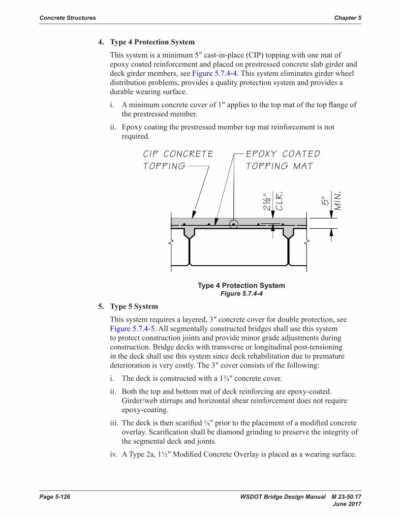
Concrete Structures Chapter 5
Page 5-126 WSDOT Bridge Design Manual M 23-50.17 June 2017
4. Type 4 Protection System
Thissystemisaminimum5″cast-in-place(CIP)toppingwithonematofepoxycoatedreinforcementandplacedonprestressedconcreteslabgirderanddeckgirdermembers,seeFigure 5.7.4-4. This system eliminates girder wheel distributionproblems,providesaqualityprotectionsystemandprovidesadurablewearingsurface.
i. Aminimumconcretecoverof1″appliestothetopmatofthetopflangeoftheprestressedmember.
ii. Epoxycoatingtheprestressedmembertopmatreinforcementisnotrequired.
Type 4 Protection SystemFigure 5.7.4-4
5. Type 5 System
Thissystemrequiresalayered,3″concretecoverfordoubleprotection,seeFigure 5.7.4-5.Allsegmentallyconstructedbridgesshallusethissystemto protect construction joints and provide minor grade adjustments during construction. Bridge decks with transverse or longitudinal post-tensioning inthedeckshallusethissystemsincedeckrehabilitationduetoprematuredeteriorationisverycostly.The3″coverconsistsofthefollowing:
i. Thedeckisconstructedwitha1¾″concretecover.
ii. Boththetopandbottommatofdeckreinforcingareepoxy-coated.Girder/webstirrupsandhorizontalshearreinforcementdoesnotrequireepoxy-coating.
iii. Thedeckisthenscarified¼″priortotheplacementofamodifiedconcreteoverlay.Scarificationshallbediamondgrindingtopreservetheintegrityofthe segmental deck and joints.
iv. AType2a,1½″ModifiedConcreteOverlayisplacedasawearingsurface.
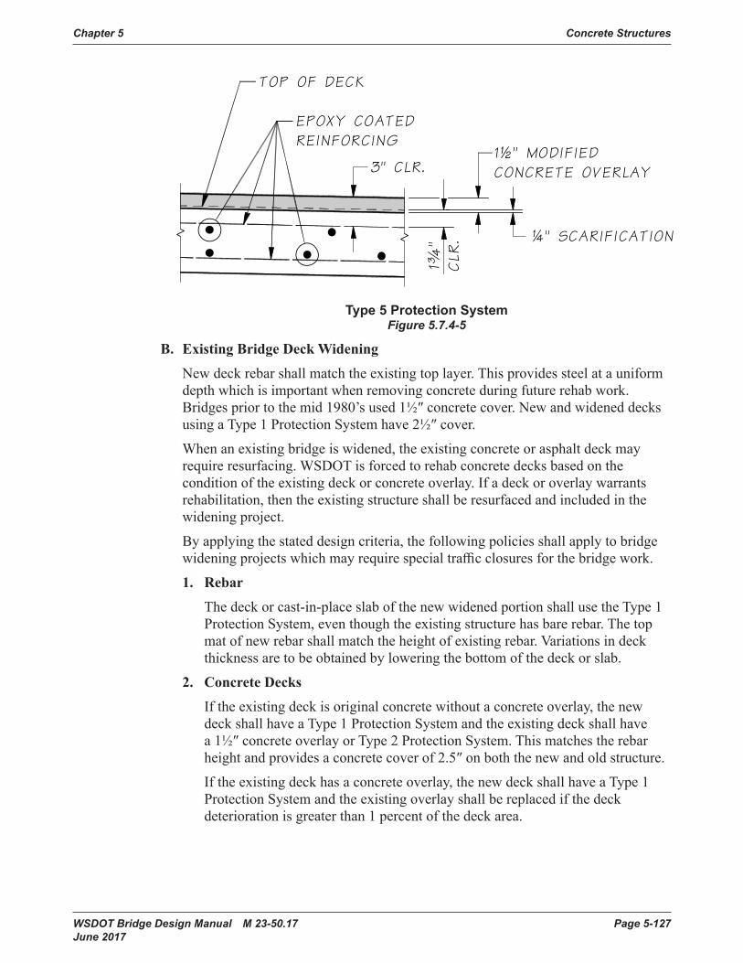
Chapter 5 Concrete Structures
WSDOT Bridge Design Manual M 23-50.17 Page 5-127 June 2017
Type 5 Protection SystemFigure 5.7.4-5
B. Existing Bridge Deck Widening
Newdeckrebarshallmatchtheexistingtoplayer.Thisprovidessteelatauniformdepthwhichisimportantwhenremovingconcreteduringfuturerehabwork.Bridgespriortothemid1980’sused1½″concretecover.NewandwideneddecksusingaType1ProtectionSystemhave2½″cover.
Whenanexistingbridgeiswidened,theexistingconcreteorasphaltdeckmayrequireresurfacing.WSDOTisforcedtorehabconcretedecksbasedonthecondition of the existing deck or concrete overlay. If a deck or overlay warrants rehabilitation,thentheexistingstructureshallberesurfacedandincludedinthewidening project.
Byapplyingthestateddesigncriteria,thefollowingpoliciesshallapplytobridgewideningprojectswhichmayrequirespecialtrafficclosuresforthebridgework.
1. Rebar
Thedeckorcast-in-placeslabofthenewwidenedportionshallusetheType1ProtectionSystem,eventhoughtheexistingstructurehasbarerebar.Thetopmatofnewrebarshallmatchtheheightofexistingrebar.Variationsindeckthicknessaretobeobtainedbyloweringthebottomofthedeckorslab.
2. Concrete Decks
If the existing deck is original concrete without a concrete overlay, the new deck shall have a Type 1 Protection System and the existing deck shall have a1½″concreteoverlayorType2ProtectionSystem.Thismatchestherebarheightandprovidesaconcretecoverof2.5″onboththenewandoldstructure.
If the existing deck has a concrete overlay, the new deck shall have a Type 1 ProtectionSystemandtheexistingoverlayshallbereplacedifthedeckdeterioration is greater than 1 percent of the deck area.

Concrete Structures Chapter 5
Page 5-128 WSDOT Bridge Design Manual M 23-50.17 June 2017
3. Concrete Overlays
Itispreferredtoplaceaconcreteoverlayfromcurbtocurb.Ifthisisproblematicfortrafficcontrol,thenPlansshallprovideatleasta6″offsetlapwhere the overlay construction joint will not match the deck construction joint.
4. HMA Overlays
Thedepthofexistingasphaltmustbefieldmeasuredandshownonthebridgeplans.Thismitigatesdamageoftheexistingstructureduetoremovaloperationsandrevealsotherdesignproblemssuchas:improperjointheight,buriedconstructionproblems,excessiveweight,orroadwaygradetransitionsadjustments due to drainage.
ThenewdeckmustmeettherebarandcovercriteriastatedaboveforConcreteDecksanddecktinningisnotrequired.Type3ProtectionsystemshallbeusedandHMAshallbeplacedtoprovideaminimum0.15′ortheoptimum0.25′.
5. Small Width Widening
With approval of the WSDOT Bridge Management Unit, smaller width wideningdesignthathastrafficonthenewconstructioncanmatchexisting1½″concretecoverforthewidenedportion,iftheexistingdeckdeteriorationisgreater than 1 percent of the deck area.
6. Expansion Joints
Alljointsshallbeingoodconditionandwatertightfortheexistingbridgeandthenewlyconstructedwidenedportion.Thefollowingjointcriteriaapplies:
i. Theexistingexpansionjointshallbereplacedif:• Morethan10percentofthelengthofajointhasrepairswithin1′-0″of
the joint.• Part of a joint is missing.• Thejointisanon-standardjointsystemplacedbymaintenance.
ii. Allexistingjointsealsshallbereplaced.
iii. When existing steel joints are not replaced in the project, the new joint shall bethesametypeandmanufacturerastheexistingsteeljoint.
iv. Steeljointsshallhavenomorethanonespliceandthespliceshallbeatalane line. Modular joints shall not have any splices.
5.7.5 Bridge Deck HMA Paving Design PoliciesThisSectionoftheBDMestablishesthecriteriausedtoprovidebridgepavingdesign options for paving projects. Bridge paving design options are customized for eachbridgebasedontheexistingconditionsandpreviouspaving.Pavingdesignersincluding paving consultants are required to request a Bridge deck Condition Report (BCR)foreachbridgewhichcontainsthepavingdesignoptionsandotherrelevantbridgeinformationforeachbridgewithintheprojectlimits.

Chapter 5 Concrete Structures
WSDOT Bridge Design Manual M 23-50.17 Page 5-129 June 2017
An asphalt wearing surface is a recognized method to manage concrete rutting, improve the ride on HMA roadways, and is a form of deck protection. Bridges may or may not have the capacity to carry the additional dead load of an asphalt wearing surface. The design options are documented for the paving project in a BCR. The BridgeOfficewillprovidebridgesheetsforstructuralitemsandtherequiredSpecialProvisionsfortheWSDOTprojects.TheBridgeOfficeProjectsandDesignEngineershouldbenotifiedearlyinthepavingdesigntoallowtimetocompleteengineeringandplan sheets.
AllWSDOTstructureswithinthedefinedprojectlimitsmustbeevaluatedforpavingorBituminousSurfaceTreatment(BSTorchipseal).Allbridgesshallbeidentifiedinthe Plans as “INCLUDED IN PROJECT” or “NOT INCLUDED” in accordance with Plan Preparation Manual Section 4 “Vicinity Map”, paragraph (n). This includes all statebridgesandnotlimitedto:
1. Offthemainline.Typicallocationsincludebridgesonramps,frontageroads,orbridgesoutofright-of-way.
2. Bridges where the main line route crosses under the structure.
3. Bridgesatthebeginningandendingstationsoftheproject.Itisnotnecessarytoincludethebridgewhenitwasrecentlyresurfaced,butitshouldbeincludedifincidental joint maintenance repairs are necessary.
Regionisresponsibleforfieldevaluationofpavingconditionandthedepthofasphaltprovidedbythelastpavingcontract.Asphaltdepthscanvaryontheconcretedeckandfrombridgetobridge.Inmostcases,asphaltdepthmeasurementsatthefoglineonthefourcornersofthedeckaresufficienttoestablishadesigndepthforcontracts.TheBridgeAssetManagershallbeinformedofthemeasurements.Pavingshownin the Plans would use an approximate or averaged value of the measurements. Some situations may require a Plan Detail showing how the depth varies for the Planing Contractor.
AstandardMicrostationdetailisavailabletosimplifydetailingofbridgepavinginthePlans,see“SH_DT_RDSECBridgeDeckOverlay_Detail”.ThetableformatiscopiedfromtheBCRandallowsthebridgepavingdesignrequirementstobelistedinthetable.Allbridgeswithinthelimitsoftheprojectmustbelistedinthetabletoclarifywhich structures do not have paving and facilitate data logging for the Washington StatePavementManagementSystemandtheBridgeOffice.
ThefollowingbridgepavingpolicieshavebeendevelopedwiththeconcurrenceofWSDOTPavementManagerstoestablishbridgeHMADesignoptionsavailableforstate managed structures.
1. Maximum HMA Depth
Bridgedecksshallbe0.25′or3″.Agreaterdepthmaybeallowedifthestructureisspecificallydesignedformorethan0.25′,suchasstructureswithballastorasapprovedbytheWSDOTLoadRatingEngineer.PavingdesignsthatincreasetheHMAmorethan3″requireanewLoadRatinganalysisandshallbesubmittedtothe WSDOT Load Rating Engineer.
a. Concretebridgedeckswithmorethan0.21′HMAmaybeexemptedfrompavingrestrictionsformill/fillHMAdesign.

Concrete Structures Chapter 5
Page 5-130 WSDOT Bridge Design Manual M 23-50.17 June 2017
b. Prestressedconcretedeckgirdersandslabswithlessthan0.25′HMArequirepaving restrictions to avoid planing the supporting structure.
c. Apavinggradechangewillberequiredwhenmorethan0.25′ofasphaltexists on a structure in order to reduce the weight on the structure and meet acceptablerailheightstandards.
2. Grade limited/0.15′
Forbridgedeckswith0.15′HMAandthegradeislimitedbybridgejointheightorother considerations, resurfacing must provide full depth removal of HMA or mill/filltheminimum0.12′.
3. Grade Transitions
WhenraisingorloweringtheHMAgradeprofileon/offorunderthebridge,themaximumrateofchangeorslopeshallbe1″/40′(1′/500′)asshowninStandard Plan A60.30.00, even if this means extending the project limits. Incorrect transitionsarethecauseofmany“bumpsatthebridge”andcreateanundesiredincreaseintruckloading.Thefollowingitemsshouldbeconsideredwhentransitioningaroadwaygrade:
a. PreviousHMAoverlaysthatraisedthegradecansignificantlyincreasetheminimum transition length.
b. Drainageconsiderationsmayrequirelongertransitionsorshouldplanetoexistingcatchbasins.
c. MainlinepavingthatraisesthegradeunderabridgemustverifyVerticalClearance remains in conformance to current Vertical Clearance requirements. Mill/Filloftheroadwayatthebridgeisgenerallydesiredunlessloweringthegrade is required.
i. Design Manual Section 720.04 Bridge Site Design Elements, (5) Vertical Clearances, (c) Minimum Clearance for Existing Structures, 1. Bridge Over a Roadway.
4. Full Removal
Full depth removal and replacement of the HMA is always an alternate resurfacing designoption.FulldepthremovalmayberequiredbytheRegionPavementManagerortheBridgeOfficeduetopoorconditionoftheHMAorbridgedeck.BridgeDeckRepairandMembraneWaterproofing(DeckSeal)standardpayitemsarerequiredforthisoptionandtheBridgeOfficewillprovideengineeringestimatesofthequantity(SF)andcostforboth.
a. BridgeDeckRepairwillberequiredwhentheHMAisremovedandtheconcrete is exposed for deck inspection. Chain Drag Testing is completed andbasedontheresults,thecontractorisdirectedtofixthequantityofdeckrepairs. The Chain Drag results are sent to the Bridge Asset Manager and usedbytheBridgeOfficetomonitortheconditionoftheconcretedeckanddeterminewhenthedeckneedsrehabilitationorreplacement.

Chapter 5 Concrete Structures
WSDOT Bridge Design Manual M 23-50.17 Page 5-131 June 2017
b. MembraneWaterproofing(DeckSeal)isStandardItem4455andwillberequiredforallHMAbridgedecks,exceptwhenthefollowingconditionsare met.
i. HMAplacedonadeckthathasaModifiedConcreteOverlaywhichactslikeamembrane.
ii. ThebridgeisontheP2replacementlistordeckrehabilitationscheduledwithinthenext4yearsortwobienniums.
5. Bare Deck HMA
PavingprojectsmayplaceHMAonabareconcretedeck,withconcurrenceoftheWSDOTBridgeAssetManager,ifthebridgeisonanHMArouteandoneofthefollowing conditions apply.
a. Ruttingontheconcretedeckis½″ormore.
b. TheRegionpreferstosimplifypavingconstructionorimprovethesmoothnessatthebridge.
Whentheconcretebridgedeckdoesnothaveasphaltonthesurface,RegionDesignshouldcontacttheRegionMaterialslabandhaveaChainDragReportcompletedandforwardedtotheBridgeAssetManagerduringdesigntoestablishthe Bridge Deck Repair quantities for the project. Pavement Design should thencontactRegionBridgeMaintenancetorequesttherepairsbecompletedpriortocontract;ortherepairsmaybeincludedinthepavingcontract.SmallamountsofBridgeDeckRepairhaveanexpensiveunitcostbycontractduringpaving operations.
6. Bridge Transverse Joint Seals
Saw cut pavement joints shown in Standard PlanA-40.20.00performbetterandhelppreventwaterproblemsattheabutmentorintheroadway.Typicalcrackinglocationswherepavementjointsealsarerequired:Endofthebridge;Endoftheapproachslab;orHMAjointsonthedeck.Standard Plan A-40.20.00, Detail 8 shall beusedatalltrusspaneljointlocations.However,ifPavementDesignersdonotseecrackingattheendsofthebridge,thensawcutjointsmaybeomittedfortheselocations. HQ Program Management has determined this work is “incidental” to P1bydefinitionandshouldbeincludedinaP1pavingprojectanduseStandardItem 6517. The following summarizes the intended application of the Details in Standard Plan A-40.20.00.
a. Detail 1
ApplieswhereHMAonthebridgesurfacebuttstotheHMAroadway.
b. Detail 2, 3, & 4
ApplieswhereconcretebridgesurfacebuttstotheHMAroadway.
c. Detail 8
Applies at truss panel joints or generic open concrete joints.
d. Detail 5, 6 &7
Forlarger1″sawcutjointsinsteadof½″jointsprovidedindetails2,3,&4.

Concrete Structures Chapter 5
Page 5-132 WSDOT Bridge Design Manual M 23-50.17 June 2017
7. BST (chip seal)
BituminousSurfaceTreatments½″thickmaybeappliedtobridgedeckswithHMA under the following conditions.
a. Plansmustidentifyorlistallstructuresbridgesincludedorexpectedwithinprojectlimitsandidentifybridgeexpansionjointsystemstobeprotected.
b. BSTisnotallowedonweightrestrictedorpostedbridges.
c. Planingwillberequiredforstructuresatthemaximumasphaltdesigndepthor the grade is limited.
ItistruethatBSTsarenotgenerallyaproblembutonlyifthestructureisnotgradelimitedbyforstructuralreasons.BCRswillspecifya½″chipsealpavingdepth of 0.03′forBSTDesigntobeconsistentwithWashingtonStatePavementManagementSystem.Plansshouldindicate½″chipsealtobeconsistentwithStandard Specifications and standard pay items.
8. Culverts and Other Structures
Culvertsorstructureswithsignificantfillanddonothaverailpostsattachedtothestructure generally will not have paving limitations. Culverts and structures with HMApavementapplieddirectlytothestructurehavebridgepavingdesignlimits.

Chapter 5 Concrete Structures
WSDOT Bridge Design Manual M 23-50.17 Page 5-133 June 2017
5.8 Cast-in-place Post-Tensioned Bridges5.8.1 Design Parameters
A. General
Post-tensioning is generally used for CIP construction and spliced prestressed concretegirderssincepretensioningisgenerallypracticalonlyforfabricator-producedstructuralmembers.ThePost-tensioned Box Girder Bridge Manual17 publishedbythePost-tensioningInstitutein1978isrecommendedastheguidefordesign.Thismanualdiscusseslongitudinalpost-tensioningofboxgirderwebsandtransversepost-tensioningofboxgirderslabs,butthemethodsapplyequallywelltoothertypesofbridges.Thefollowingrecommendationsareintendedtoaugmentthe PTI Manual and the AASHTO LRFD Specifications and point out where current WSDOT practice departs from practices followed elsewhere.
TheAASHTOcriteriaforreinforcedconcreteapplyequallytobridgeswithorwithout post-tensioning steel. However, designers should note certain requirements unique to prestressed concrete such as special φ-factors, load factors and shear provisions.
Post-tensioning consists of installing steel tendons into a hollow duct in a structure after the concrete sections are cast. These tendons are usually anchored at each end of the structure and stressed to a design strength using a hydraulic jacking system. Afterthetendonhasbeenstressed,theductisfilledwithgroutwhichbondsthetendon to the concrete section and prevents corrosion of the strand. The anchor heads are then encased in concrete to provide corrosion protection.
B. Bridge Types
Post-tensioninghasbeenusedinvarioustypesofCIPbridgesinWashingtonStatewithboxgirderspredominating.SeeAppendix 5-B4 for a comprehensive list of boxgirderdesigns.Thefollowingaresomeexamplesofotherbridgetypes:
KitsapCounty,Contract9788,Multi-SpanSlab
Peninsula Drive, Contract 5898, Two- Span Box Girder
Covington Way to 180th Avenue SE, Contract 4919, Two-Span Box Girder Longitudinal Post-tensioning
Snohomish River Bridge, Contract 4444, Multi-Span Box Girder Longitudinal Post-tensioning
See Section 2.4.1forstructuretypecomparisonofpost-tensionedconcreteboxgirderbridgestootherstructures.Ingeneral,apost-tensionedCIPbridgecanhaveasmallerdepth-to-spanratiothanthesamebridgewithconventionalreinforcement.Thisisanimportantadvantagewhereminimumstructuredepthisdesirable.However,structuredepthmustbedeepenoughtoaccommodateanchorages.
Concrete Structures Chapter 5
Page 5-134 WSDOT Bridge Design Manual M 23-50.17 June 2017
1. Slab Bridge
Structuredepthcanbequiteshallowinthepositivemomentregionwhenpost-tensioningiscombinedwithhaunchinginthenegativemomentregion.However, post-tensioned CIPslabsareusuallymoreexpensivethanwhenreinforced conventionally. Designers should proceed with caution when consideringpost-tensionedslabbridgesbecauseseverecrackinginthedecksofbridgesofthistypehasoccurred21, 22, 23.
TheOlallaBridge(Contract9202)couldbereviewedasanexample.Thisbridgehasspansof41.5′–50′–41.5′,amidspanstructuredepthof15inches,andsome haunching at the piers.
2. T-Beam Bridge
Thistypeofbridge,combinedwithtaperedcolumns,canbestructurallyefficientandaestheticallypleasing,particularlywhenthespacingofthebeamsandthecolumnsarethesame.AT-Beambridgecanalsobeagoodchoiceforasingle-span simply-supported structure.
Whenequallyspacedbeamsandcolumnsareusedinthedesign,thewidthofbeamwebsshouldgenerallybeequaltothewidthofthesupportingcolumns.SeeSR16,UnionAvenueO’Xings,foranexample.Sincelongitudinalstructuralframeactionpredominatesinthistypeofdesign,crossbeamsatintermediatepierscanberelativelysmallandthepost-tensioningtendonscanbeplacedside-by-sideinthewebs,resultinginanefficientcenterofgravityofsteellinethroughout.ForothertypesofT-Beambridges,thepreferredsolutionmaybesmaller,morecloselyspacedbeamsandfewer,butlargerpier elements. If this type of construction is used in a multispan, continuous bridge,thebeamcross-sectionpropertiesinthenegativemomentregionsneedtobeconsiderablylargerthanthepropertiesinthepositivemomentregionstoresist compression.
Largersectionpropertiescanbeobtainedbygraduallyincreasingthewebthicknessinthevicinityofintermediatepiersor,ifpossible,byaddingafilletorhaunch.Thedeckslaboverhangoverexteriorwebsshouldberoughlyhalfthewebspacing.
3. Box Girder Bridge
Thistypeofbridgehasbeenapopularchoiceinthisstate.Thecostofaprestressedboxgirderbridgeispracticallythesameasaconventionally-reinforcedboxgirderbridge,however,longerspansandshallowerdepthsarepossiblewithprestressing.
Thesuperstructureofmulti-cellboxgirdersshallbedesignedasaunit.Theentiresuperstructuresection(trafficbarrierexcluded)shallbeconsideredwhencomputing the section properties.
Forcriteriaondistributionofliveloads,seeSection 3.9.4.Allslendermemberssubjectedtocompressionmustsatisfybucklingcriteria.
Webspacingshouldnormallybe8to11feetandthetopslaboverhangoverexteriorgirdersshouldbeapproximatelyhalfthegirderspacingunlesstransversepost-tensioningisused.Theapparentvisualdepthofboxgirder
Chapter 5 Concrete Structures
WSDOT Bridge Design Manual M 23-50.17 Page 5-135 June 2017
bridgescanbereducedbyslopingallorthelowerportionoftheexteriorweb.Ifthelatterisdone,theoverallstructuredepthmayhavetobeincreased.Webthicknessshouldbe12inchesminimum,butnotlessthanrequiredforshear,horizontal and vertical reinforcing, duct placement, and for concrete placing clearance.Providing2½″ofclearcoverexpeditesconcreteplacementandconsolidation in the heavily congested regions adjacent to the post-tensioning ducts.Websshouldbeflaredatanchorages.Topandbottomslabthicknessshould normally meet the requirements of Section 5.3.1.B,butnotlessthanrequiredbystressandspecifications.Generally,thebottomslabwouldrequirethickeningattheinteriorpiersofcontinuousspans.Thisthickeningshouldbeaccomplishedbyraisingthetopsurfaceofthebottomslabatthemaximumrateof½″perfoot.
C. Strand and Tendon Arrangements
Thetotalnumberofstrandsselectedshouldbetheminimumrequiredtomeetthe strength and service limit state requirements at all points. Duct sizes and the numberofstrandstheycontainvaryslightly,dependingonthesupplier.Chapter2of the PTI Post-tensioned Box Girder Bridge Manual, and shop drawings of the recentpost-tensionedbridgeskeptonfileintheConstructionPlansSectionofferguidancetostrandselection.Ingeneral,asupplierwillofferseveralductsizesandassociatedendanchors,eachofwhichwillaccommodatearangeofstrandnumbersup to a maximum in the range. Present WSDOT practice is to indicate only the designforceandcablepathonthecontractplansandallowthepost-tensioningsupplier to satisfy these requirements with tendons and anchors. The most economicaltendonselectionwillgenerallybethemaximumsizewithintherange.Commonly-stockedanchoragesfor½″diameterstrandsinclude9,12,19,27,31,and37strands.Commonly-stockedanchoragesfor0.6″diameterstrandsinclude4,7, 12, 19, 22, and 27 strands. The design should utilize commonly-stocked items. Forexample,adesignrequiring72strandsperwebwouldbemosteconomicallysatisfiedbytwostandard37-strandtendons.Alesseconomicalchoicewouldbethree standard 27-strand tendons containing 24 strands each. Tendons shall not belargerthan(37)½″strandunitsor(27)0.6″strandunits,unlessspecificallyapprovedbytheWSDOTBridgeDesignEngineer.Theductareashallbeatleast 2.5 times the net area of the prestressing steel. In the regions away from the end anchorages, the duct placement patterns indicated in Figures 5.8.1-1 through 5.8.1-3shallbeused.
Althoughpost-tensioningsteelnormallytakesprecedenceinamember,sufficientroommustbeprovidedforotheressentialmildsteelandplacementofconcrete,inparticularneardiaphragmsandcross-beams.
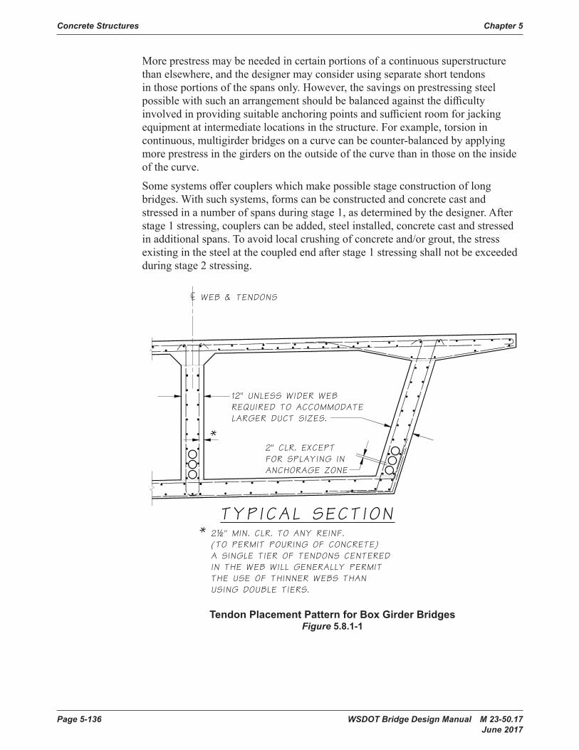
Concrete Structures Chapter 5
Page 5-136 WSDOT Bridge Design Manual M 23-50.17 June 2017
Moreprestressmaybeneededincertainportionsofacontinuoussuperstructurethan elsewhere, and the designer may consider using separate short tendons in those portions of the spans only. However, the savings on prestressing steel possiblewithsuchanarrangementshouldbebalancedagainstthedifficultyinvolvedinprovidingsuitableanchoringpointsandsufficientroomforjackingequipment at intermediate locations in the structure. For example, torsion in continuous,multigirderbridgesonacurvecanbecounter-balancedbyapplyingmore prestress in the girders on the outside of the curve than in those on the inside of the curve.
Somesystemsoffercouplerswhichmakepossiblestageconstructionoflongbridges.Withsuchsystems,formscanbeconstructedandconcretecastandstressedinanumberofspansduringstage1,asdeterminedbythedesigner.Afterstage1stressing,couplerscanbeadded,steelinstalled,concretecastandstressedin additional spans. To avoid local crushing of concrete and/or grout, the stress existinginthesteelatthecoupledendafterstage1stressingshallnotbeexceededduring stage 2 stressing.
Chapter 5Concrete Structures
*
2" CLR. EXCEPT FOR SPLAYING INANCHORAGE ZONE
¢ WEB & TENDONS
12" UNLESS WIDER WEBREQUIRED TO ACCOMMODATELARGER DUCT SIZES.
2½" MIN. CLR. TO ANY REINF.(TO PERMIT POURING OF CONCRETE)A SINGLE TIER OF TENDONS CENTEREDIN THE WEB WILL GENERALLY PERMITTHE USE OF THINNER WEBS THANUSING DOUBLE TIERS.
*
TYPICAL SECTION
Tendon Placement Patternfor Box Girder Bridges
Figure 5.8.1-1
Tendon Placement Pattern for Box Girder BridgesFigure 5.8.1-1

Chapter 5 Concrete Structures
WSDOT Bridge Design Manual M 23-50.17 Page 5-137 June 2017
Chapter 5Concrete Structures
2" MIN. CLR
.(T
YP.)
2" MIN.
CLR
.
DUCTS 2 " O.D. TO 3" O.D.
DUCTS OVER 3" O.D.
BUNDLED DUCTS
Tendon Placement Pattern for Box Girder BridgesFigure 5.8.1-2
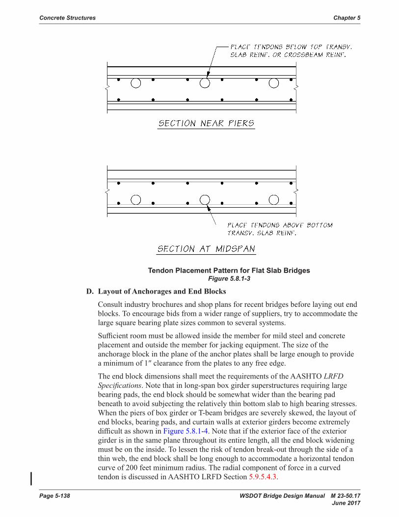
Concrete Structures Chapter 5
Page 5-138 WSDOT Bridge Design Manual M 23-50.17 June 2017
Tendon Placement Pattern for Flat Slab BridgesFigure 5.8.1-3
D. Layout of Anchorages and End Blocks
Consultindustrybrochuresandshopplansforrecentbridgesbeforelayingoutendblocks.Toencouragebidsfromawiderrangeofsuppliers,trytoaccommodatethelargesquarebearingplatesizescommontoseveralsystems.
Sufficientroommustbeallowedinsidethememberformildsteelandconcreteplacementandoutsidethememberforjackingequipment.Thesizeoftheanchorageblockintheplaneoftheanchorplatesshallbelargeenoughtoprovideaminimumof1″clearancefromtheplatestoanyfreeedge.
Theendblockdimensionsshall meet the requirements of the AASHTO LRFD Specifications.Notethatinlong-spanboxgirdersuperstructuresrequiringlargebearingpads,theendblockshouldbesomewhatwiderthanthebearingpadbeneathtoavoidsubjectingtherelativelythinbottomslabtohighbearingstresses.WhenthepiersofboxgirderorT-beambridgesareseverelyskewed,thelayoutofendblocks,bearingpads,andcurtainwallsatexteriorgirdersbecomeextremelydifficultasshowninFigure 5.8.1-4. Note that if the exterior face of the exterior girderisinthesameplanethroughoutitsentirelength,alltheendblockwideningmustbeontheinside.Tolessentheriskoftendonbreak-outthroughthesideofathinweb,theendblockshallbelongenoughtoaccommodateahorizontaltendoncurve of 200 feet minimum radius. The radial component of force in a curved tendon is discussed in AASHTO LRFD Section 5.9.5.4.3.
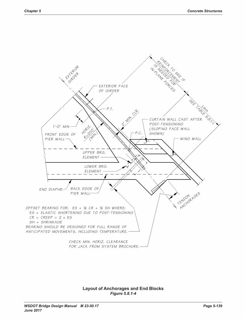
Chapter 5 Concrete Structures
WSDOT Bridge Design Manual M 23-50.17 Page 5-139 June 2017
Chapter 5Concrete Structures
END DIAPHR.
OFFSET BEARING FOR: ES + ½ CR + ½ SH WHERE: ES = ELASTIC SHORTENING DUE TO POST-TENSIONING CR = CREEP = 2 x ES SH = SHRINKAGEBEARING SHOULD BE DESIGNED FOR FULL RANGE OFANTICIPATED MOVEMENTS, INCLUDING TEMPERATURE.
BACK EDGE OFPIER WALL
CHECK MIN. HORIZ. CLEARANCEFOR JACK FROM SYSTEM BROCHURE.
2" MIN. CLR.
HORIZ.
R=200'
(MIN.)
¢ TEND
ON
ANC
HORA
GES
UPPER BRG.ELEMENT
LOWER BRG.ELEMENT
FRONT EDGE OFPIER WALL
EXTERIOR FACEOF GIRDER
P.T.
CURTAIN WALL CAST AFTERPOST-TENSIONING(SLOPING FACE WALLSHOWN)
WING WALL
¢ EXTERIOR
GIRDER
1'-0" MIN
P.C.
CHECK TO SEE IF
REINFORCEMENT
IS NEEDED FOR
IN-PLANE FORCES
Lmin
SEE TABLE 5.8.1-1
Layout of Anchorages and End BlocksFigure 5.8.1-4
Layout of Anchorages and End BlocksFigure 5.8.1-4

Concrete Structures Chapter 5
Page 5-140 WSDOT Bridge Design Manual M 23-50.17 June 2017
Allpost-tensioninganchoragesinwebsofboxgirderormultistemsuperstructuresshallbeverticallyaligned.SpecialAnchorageDevicesmaybeusedtoavoidastaggeredanchoragelayout.Ifastaggeredlayoutmustbeused,theplansshallbereviewedandapprovedbytheWSDOTBridgeDesignEngineer.
Toensuremaximumanchorageefficiency,maximumfatiguelifeandpreventionofstrandbreakage,aminimumtangentlengthattheanchorageisrequiredtoensurethat the strands enter the anchorage without kinking.
To prevent excessive friction loss and damage to the prestressing sheathings, adherence to the minimum tendon radii is required.
Table5.8.1-1andFigure5.8.1-5presenttherequiredminimumradiusofcurvaturealong with the required minimum tangent lengths at stressing anchorages. Deviation from these requirements needs the approval of the WSDOT Bridge Design Engineer.
Anchor Types Radii, ft.Tangent
Length, ft.½” Diameter Strand Tendons
5-4 7 .5 2 .65-7 9 .8 2 .6
5-12 13 .5 3 .35-19 17 .7 3 .35-27 21 .0 3 .35-31 22 .3 4 .95-37 24 .0 4 .9
0.6” Diameter Strand Tendons6-4 10 .6 3 .36-7 12 .8 3 .3
6-12 16 .4 3 .36-19 20 .7 4 .96-22 22 .6 4 .96-31 26 .4 4 .9
Minimum Tendon Radii and Tangent LengthTable 5.8.1-1
minimum tangent length at the anchorage is required to ensure that the strands enter the anchorage without excessive kinking.
To prevent excessive friction loss and damage to the prestressing sheathings, adherence to the minimum tendon radii is required.
Table5.8.1-1 and Figure 5.8.1-5 present the required minimum radius of curvature along with the required minimum tangent lengths at stressing anchorages. Deviation from these requirements needs the approval of the WSDOT Bridge Design Engineer.
AnchorTypes
Radii, ft. Tangent Length, ft.
½” Diameter Strand Tendons5-4 7.5 2.65-7 9.8 2.6
5-12 13.5 3.35-19 17.7 3.35-27 21.0 3.35-31 22.3 4.95-37 24.0 4.9
0.6” Diameter Strand Tendons6-4 10.6 3.36-7 12.8 3.3
6-12 16.4 3.36-19 20.7 4.96-22 22.6 4.96-31 26.4 4.9
Table5.8.1-1:Minimum Tendon Radii and Tangent Length
Tangent Length and Tendon RadiiFigure 5.8.1-5
E. Superstructure Shortening – Whenevermemberssuchascolumns,crossbeams,anddiaphragmsareappreciablyaffectedbypost-tensioningofthemaingirders,thoseeffectsshallbeincludedinthedesign.Thiswillgenerallybetrueinstructurescontainingrigidframeelements.Forfurther discussion,
Formatted: Centered
Formatted: Centered
Formatted: Centered
Formatted: Centered
Formatted: Centered
Formatted: Centered
Formatted: Centered
Formatted: Centered
Formatted: Centered
Formatted: Centered
Formatted: Centered
Formatted: Centered
Formatted: Centered
Formatted: Centered
Formatted: Centered
Formatted: Centered
Formatted: Level 1, Centered, Indent: Firstline: 0", Tab stops: Not at 6.25"
Formatted: Level 1, Indent: First line: 0",Tab stops: Not at 6.25"
Tangent Length and Tendon RadiiFigure 5.8.1-5
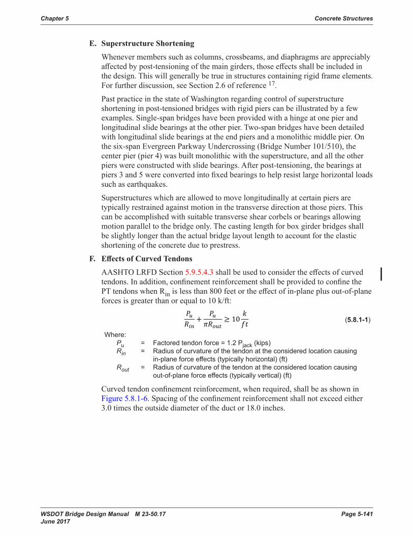
Chapter 5 Concrete Structures
WSDOT Bridge Design Manual M 23-50.17 Page 5-141 June 2017
E. Superstructure Shortening
Whenevermemberssuchascolumns,crossbeams,anddiaphragmsareappreciablyaffectedbypost-tensioningofthemaingirders,thoseeffectsshallbeincludedinthedesign.Thiswillgenerallybetrueinstructurescontainingrigidframeelements.For further discussion, see Section 2.6 of reference 17.
Past practice in the state of Washington regarding control of superstructure shorteninginpost-tensionedbridgeswithrigidpierscanbeillustratedbyafewexamples.Single-spanbridgeshavebeenprovidedwithahingeatonepierandlongitudinalslidebearingsattheotherpier.Two-spanbridgeshavebeendetailedwithlongitudinalslidebearingsattheendpiersandamonolithicmiddlepier.Onthe six-span Evergreen Parkway Undercrossing (BridgeNumber101/510), the centerpier(pier4)wasbuiltmonolithicwiththesuperstructure,andalltheotherpierswereconstructedwithslidebearings.Afterpost-tensioning,thebearingsatpiers3and5wereconvertedintofixedbearingstohelpresistlargehorizontalloadssuch as earthquakes.
Superstructures which are allowed to move longitudinally at certain piers are typically restrained against motion in the transverse direction at those piers. This canbeaccomplishedwithsuitabletransverseshearcorbelsorbearingsallowingmotionparalleltothebridgeonly.Thecastinglengthforboxgirderbridgesshallbeslightlylongerthantheactualbridgelayoutlengthtoaccountfortheelasticshortening of the concrete due to prestress.
F. Effects of Curved Tendons
AASHTO LRFD Section 5.9.5.4.3shallbeusedtoconsidertheeffectsofcurvedtendons.Inaddition,confinementreinforcementshallbeprovidedtoconfinethePT tendons when Rin islessthan800feetortheeffectofin-planeplus out-of-plane forces isgreaterthanorequalto10k/ft:
(5.8.1-1)
Where: Pu = Factored tendon force = 1 .2 Pjack (kips) Rin = Radius of curvature of the tendon at the considered location causing in-plane force effects (typically horizontal) (ft) Rout = Radius of curvature of the tendon at the considered location causing out-of-plane force effects (typically vertical) (ft)
Curvedtendonconfinementreinforcement,whenrequired,shallbeasshowninFigure 5.8.1-6.Spacingoftheconfinementreinforcementshallnotexceedeither3.0 times the outside diameter of the duct or 18.0 inches.
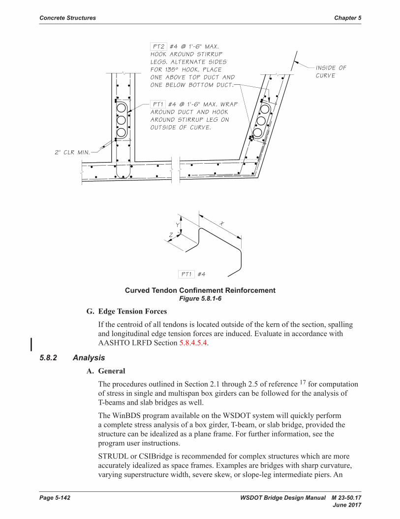
Concrete Structures Chapter 5
Page 5-142 WSDOT Bridge Design Manual M 23-50.17 June 2017
Chapter 5Concrete Structures
Curved Tendon Confinement ReinforcementFigure 5.8.1-6
PT1 #4 @ 1'-6" MAX. WRAPAROUND DUCT AND HOOKAROUND STIRRUP LEG ONOUTSIDE OF CURVE.
INSIDE OFCURVE
PT2 #4 @ 1'-6" MAX.HOOK AROUND STIRRUPLEGS. ALTERNATE SIDESFOR 135° HOOK. PLACEONE ABOVE TOP DUCT ANDONE BELOW BOTTOM DUCT.
2" CLR MIN.
PT1 #4
Z
Y X
Curved Tendon Confinement ReinforcementFigure 5.8.1-6
G. Edge Tension Forces
If the centroid of all tendons is located outside of the kern of the section, spalling and longitudinal edge tension forces are induced. Evaluate in accordance with AASHTO LRFD Section 5.8.4.5.4.
5.8.2 AnalysisA. General
The procedures outlined in Section 2.1 through 2.5 of reference 17 for computation ofstressinsingleandmultispanboxgirderscanbefollowedfortheanalysisofT-beamsandslabbridgesaswell.
TheWinBDSprogramavailableontheWSDOTsystemwillquicklyperformacompletestressanalysisofaboxgirder,T-beam,orslabbridge,providedthestructurecanbeidealizedasaplaneframe.Forfurtherinformation,seetheprogram user instructions.
STRUDL or CSIBridge is recommended for complex structures which are more accuratelyidealizedasspaceframes.Examplesarebridgeswithsharpcurvature,varying superstructure width, severe skew, or slope-leg intermediate piers. An

Chapter 5 Concrete Structures
WSDOT Bridge Design Manual M 23-50.17 Page 5-143 June 2017
analysis method in Chapter 10 of reference18forcontinuousprestressedbeamsisparticularly well adapted to the loading input format in STRUDL. In the method, theforcesexertedbycablesofparabolicorotherconfigurationsareconvertedintoequivalentverticallinearorconcentratedloadsappliedtomembersandjointsof the superstructure. The vertical loads are considered positive when acting up toward the center of tendon curvature and negative when acting down toward the centeroftendoncurvature.Forcesexertedbyanchorplatesatthecableendsarecodedinasaxialandverticalconcentratedforcescombinedwithaconcentratedmoment if the anchor plate group is eccentric. Since the prestress force varies alongthespansduetotheeffectsoffriction,thedifferencebetweentheexternalforcesappliedattheendanchorsatoppositeendsofthebridgemustbecodedinat various points along the spans in order for the summation of horizontal forces toequalzero.Withcorrectinput,theeffectsofelasticshorteningandsecondarymomentsareproperlyreflectedinalloutput,andtheprestressmomentsprintedoutare the actual resultant (total) moments acting on the structure. For examples of the application of STRUDL to post-tensioning design, see the calculations for I-90 West Sunset Way Ramp and the STRUDL/CSI Bridge manuals.
B. Section Properties
Asinothertypesofbridges,thedesignnormallybeginswithapreliminaryestimate of the superstructure cross-section and the amount of prestress needed at pointsofmaximumstressandatpointsofcross-sectionchange.Forboxgirders,see Figures 2-0 through 2-5 of Reference17.ForT-beamandslabbridges,previousdesignsareausefulguideinmakingagoodfirstchoice.
For frame analysis, use the properties of the entire superstructure regardless of the typeofbridgebeingdesigned.Forstressanalysisofslabbridges,calculateloadsandsteelrequirementsfora1′widestrip.ForstressanalysisofT-beambridges,usethe procedures outlined in the AASHTO LRFD Specifications.
Notethatwhendifferentconcretestrengthsareusedindifferentportionsofthesamemember,theequivalentsectionpropertiesshallbecalculatedintermsofeither the stronger or weaker material. In general, the concrete strength shallbelimited to the values indicated in Section 5.1.1.
C. Preliminary Stress Check
InaccordancewithAASHTO,flexuralstressesinprestressedmembersarecalculated at service load levels. Shear stresses, stirrups, moment capacities vs. applied moments are calculated at ultimate load levels.
Duringpreliminarydesign,thefirstobjectiveshouldbetosatisfytheallowableflexuralstressesintheconcreteatthecriticalpointsinthestructurewiththechosencross-section and amount of prestressing steel, then the requirements for shear stress,stirrups,andultimatemomentcapacitycanbereadilymetwithminorornomodificationsinthecross-section.Forexample,girderwebscanbethickenedlocally near piers to reduce excessive shear stress.
IntheAASHTOformulasforallowabletensilestressinconcrete,bondedreinforcementshouldbeinterpretedtomeanbondedauxiliary(nonprestressed)reinforcement in conformity with Article 8.6 of the 2002 ACI Code for Analysis
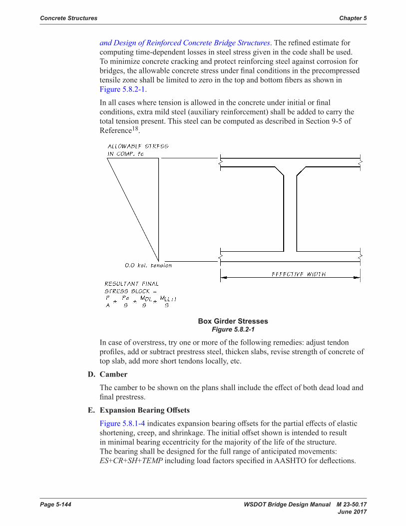
Concrete Structures Chapter 5
Page 5-144 WSDOT Bridge Design Manual M 23-50.17 June 2017
and Design of Reinforced Concrete Bridge Structures. The refinedestimate for computing time-dependent losses in steel stress given in the code shallbeused.To minimize concrete cracking and protect reinforcing steel against corrosion for bridges,theallowableconcretestressunderfinalconditionsintheprecompressedtensile zone shallbelimitedtozerointhetopandbottomfibersasshowninFigure 5.8.2-1.
Inallcaseswheretensionisallowedintheconcreteunderinitialorfinalconditions, extra mild steel (auxiliary reinforcement) shallbeaddedtocarrythetotaltensionpresent.ThissteelcanbecomputedasdescribedinSection9-5ofReference18.
Box Girder StressesFigure 5.8.2-1
Incaseofoverstress,tryoneormoreofthefollowingremedies:adjusttendonprofiles,addorsubtractprestresssteel,thickenslabs,revisestrengthofconcreteoftopslab,addmoreshorttendonslocally,etc.
D. Camber
Thecambertobeshownontheplansshallincludetheeffectofbothdeadloadandfinalprestress.
E. Expansion Bearing Offsets
Figure 5.8.1-4 indicatesexpansionbearingoffsetsforthepartialeffectsofelasticshortening,creep,andshrinkage.Theinitialoffsetshownisintendedtoresultinminimalbearingeccentricityforthemajorityofthelifeofthestructure.Thebearingshallbedesignedforthefullrangeofanticipatedmovements:ES+CR+SH+TEMP includingloadfactorsspecifiedinAASHTOfordeflections.

Chapter 5 Concrete Structures
WSDOT Bridge Design Manual M 23-50.17 Page 5-145 June 2017
5.8.3 Post-tensioning A. Tendon Layout
Afterapreliminaryestimatehasbeenmadeoftheconcretesectionandtheamountofprestressingneededatpointsofmaximumappliedload,itmaybeadvantageousinmultispanbridgestodrawatendonprofiletoaconvenientscalesuperimposedonaplotofthecenterofgravityofconcrete(c.g.c.)line.Themostefficienttendonprofilefromthestandpointofsteelstresslosswillnormallybeaseriesofratherlonginterconnectedparabolas,butotherconfigurationsarepossible.Forcontinuousbridgeswithunequalspanlengths,thetendonprofile(eccentricity)shallbebasedonthespanrequirement.Thisresultsinanefficientpost-tensioningdesign.Thetendonprofileandc.g.c.lineplotisstronglyrecommendedforsuperstructuresofvariablecross-sectionand/ormultipleunsymmetricalspanarrangements,butisnotnecessaryforsuperstructureshavingconstantcross-sectionandsymmetricalspans.Themainadvantagesofthetendonprofileandc.g.c.plotare:
1. The primary prestress moment curves (prestress force times distance from c.g.c. line to center of gravity of steel (c.g.s.) lines) at all points throughout allspansarequicklyobtainedfromthisplotandwillbeusedtodevelopthesecondary moment curves (if present) and, ultimately, to develop the resultant total prestress moment curve.
2. Possibleconflictsbetweenprestressingsteelandmildsteelnearendregions,crossbeams,anddiaphragmsmaybecomeapparent.
3. Possibledesignrevisionsmaybeindicated.Forexample,camberinbridgeswithunequalspanscanbebalancedbyadjustingtendonprofiles.
Thetendonprofileandc.g.c.linediagramshall also contain a sketch of how theendbearingplatesoranchorsaretobearrangedattheendsofthebridge.Suchasketchcanbeusefulindetermininghowlargetheendblockinagirderbridgewillhavetobeandhowmuchspacewillberequiredformildsteelintheendregion.Ingeneral,thearrangementofanchorplatesshouldbethesameasthearrangementoftheductstowhichtheybelongtoavoidproblemswithductcross-oversandtokeependblocksofreasonablewidth.
B. Prestress Losses
PrestresslossesshallbeasindicatedinSection 5.1.4.
Concrete Structures Chapter 5
Page 5-146 WSDOT Bridge Design Manual M 23-50.17 June 2017
C. Jacking End
Effectiveprestressingforceindesignofpost-tensionedbridgesdependsontheaccumulation of friction losses due to the horizontal and vertical curvature of the tendonsaswellasthecurvatureofthebridge.Althoughjackingendsofpost-tensionedbridgesisimportanttoachievemoreeffectivedesign,considerationshallbegiventothepracticalityofjackingduringconstruction.Thefollowinggeneralstressingguidelinesshallbeconsideredinspecifyingjackingendofpost-tensionedbridges.• All simple or multiple span CIPorprecastconcretebridgeswithtotallengthoflessthan350′shallbestressedfromoneendonly.
• All CIPorprecastconcreteposttensionedbridgeswithtotallengthbetween350′to600′.maybestressedfromoneendorbothendsifgreaterfrictionlosses due to vertical orhorizontalcurvaturearejustifiedbythedesigner.
• All CIPorprecastconcretebridgeswithtotallengthofgreaterthan600′shallbestressedfrombothends.
Whenstressingtendonsfrombothendsorwhenalternatingasinglepullfrombothends (half tendons pulled from one end with the other half pulled from the other end),alltendonsshallbestressedononeendbeforealltendonsarestressedontheopposite end.
Stressingatbothendsshallpreferablybedoneonalternatetendons,andneednotbedonesimultaneouslyonthesametendon.Inrarecases,tendonscanbestressedfrombothendstoreducelargetendonlossesbutisundesirableduetoworkersafety issues and a reduction in stressing redundancy.
D. Steel Stress Curve
Steelstressesmaybeplottedeitherastheactualvaluesorasapercentageofthejackingstresses.Asteelstressdiagramforatypicaltwo-spanbridgeisshownin Figure 5.8.3-1.Spansaresymmetricalaboutpier2andthebridgeisjackedfrombothends.
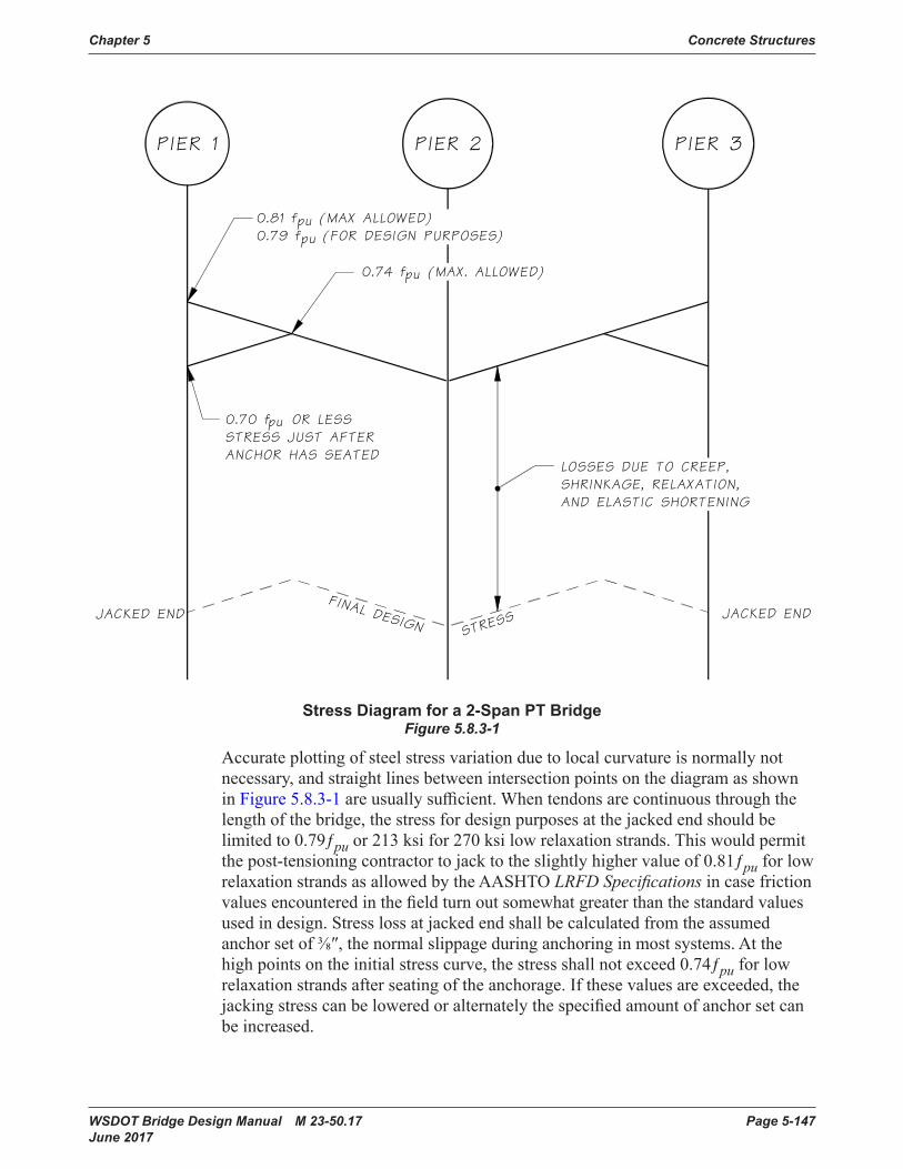
Chapter 5 Concrete Structures
WSDOT Bridge Design Manual M 23-50.17 Page 5-147 June 2017
Chapter 5Concrete Structures
PIER 1 PIER 2 PIER 3
0.81 f (MAX ALLOWED)0.79 f (FOR DESIGN PURPOSES)
pupu
FINAL DESIGNJACKED END
STRESSJACKED END
pu
LOSSES DUE TO CREEP,SHRINKAGE, RELAXATION,AND ELASTIC SHORTENING
0.70 f OR LESSSTRESS JUST AFTERANCHOR HAS SEATED
0.74 f (MAX. ALLOWED)pu
Stress Diagram for a 2-span PT BridgeFigure 5.8.3-1
Stress Diagram for a 2-Span PT BridgeFigure 5.8.3-1
Accurate plotting of steel stress variation due to local curvature is normally not necessary,andstraightlinesbetweenintersectionpointsonthediagramasshownin Figure 5.8.3-1areusuallysufficient.Whentendonsarecontinuousthroughthelengthofthebridge,thestressfordesignpurposesatthejackedendshouldbelimitedto0.79ƒpu or 213 ksi for 270 ksi low relaxation strands. This would permit thepost-tensioningcontractortojacktotheslightlyhighervalueof0.81ƒpu for low relaxationstrandsasallowedbytheAASHTOLRFD Specifications in case friction valuesencounteredinthefieldturnoutsomewhatgreaterthanthestandardvaluesused in design. Stress loss at jacked end shallbecalculatedfromtheassumedanchorsetof⅜″,thenormalslippageduringanchoringinmostsystems.Atthehigh points on the initial stress curve, the stress shallnotexceed0.74ƒpu for low relaxation strands after seating of the anchorage. If these values are exceeded, the jackingstresscanbeloweredoralternatelythespecifiedamountofanchorsetcanbeincreased.

Concrete Structures Chapter 5
Page 5-148 WSDOT Bridge Design Manual M 23-50.17 June 2017
When the total tendon length (L)islessthanthelengthofcableinfluencedbyanchor set (x)andthefrictionlossissmall,asinshortstraighttendons,the0.70ƒpu value at the anchorage immediately after anchor set governs. In these cases, the allowablejackingstressvalueattheanchoragecannotbeusedandaslightlylowervalue shallbespecified.
In single-span, simply supported superstructures friction losses are so small that jackingfrombothendsisnormallynotwarranted.Inthelongermultispanbridgeswherethetendonsexperiencegreaterfrictionlosses,jackingfrombothendswillusuallybenecessary.Jackingatbothendsneednotbedonesimultaneously,sincefinalresultsarevirtuallythesamewhetherornotthejackingissimultaneous.Ifunsymmetricaltwo-spanstructuresaretobejackedfromoneendonly,thejackingmustbedonefromtheendofthelongestspan.
Intheabsenceofexperimentaldata,thefrictioncoefficientforpost-tensioningtendons in rigid and semi-rigid galvanized metal sheathing shallbetakenasshown in Table5.8.3-1. For tendon lengths greater than 1,000 feet, investigation is warrantedoncurrentfielddataofsimilarlengthbridgesforappropriatevaluesofµ.Intheabsenceofexperimentaldata,thefrictioncoefficientforpost-tensioningtendonsinpolyethyleneductsshallbetakenasshownintheAASHTOLRFD Bridge Design Specifications.
Tendon Length µ500 ft or less 0 .15
Over 500 ft to 750 ft 0 .20Over 750 ft to 1,000 ft 0 .25
Friction Coefficients for Post-tensioning Tendons in Metal Ducts
Table 5.8.3-1
For tendon lengths greater than 1,000 feet, investigation is warranted on current fielddataofsimilarlengthbridgesforappropriatevaluesofµ.
E. Flexural Stress in Concrete
Stressatserviceloadlevelsinthetopandbottomfibersofprestressedmembersshallbecheckedforatleasttwoconditionsthatwilloccurinthelifetimeofthemembers.Theinitialconditionoccursjustafterthetransferofprestresswhentheconcreteisrelativelyfreshandthememberiscarryingitsowndeadload.Thefinalcondition occurs after all the prestress losses when the concrete has gained its full ultimatestrengthandthememberiscarryingdeadloadandliveload.Forcertainbridges,otherintermediateloadingconditionsmayhavetobechecked,suchaswhen prestressing and false work release are done in stages and when special constructionloadshavetobecarried,etc.TheconcretestressesshallbewithintheAASHTO LRFD SpecificationallowableexceptasamendedinSection 5.2.1.
Insingle-spansimplysupportedsuperstructureswithparabolictendonpaths,flexuralstressesatserviceloadlevelsneedtobeinvestigatedatthespanmidpointwhere moments are maximum, at points where the cross-section changes, and near thespanendswhereshearstressislikelytobemaximum(seeSection 5.8.4 Shear). Fortendonpathsotherthanparabolic,flexuralstressshallbeinvestigatedatotherpoints in the span as well.
Chapter 5 Concrete Structures
WSDOT Bridge Design Manual M 23-50.17 Page 5-149 June 2017
Inmultispancontinuoussuperstructures,investigateflexuralstressatpointsofmaximummoment(inthenegativemomentregionofboxgirders,checkatthequarterpointofthecrossbeam),atpointswherethecrosssectionchanges,andatpointswhereshearislikelytobemaximum.Normally,mildsteelshouldnotbeusedtosupplementtheultimatemomentcapacity.Itmaybenecessary,however,to determine the partial temperature and shrinkage stresses that occur prior to post-tensioning and supply mild steel reinforcing for this condition.
In addition, maximum and minimum steel percentages and cracking moment shall bechecked.SeeSection 2.3.8 of Reference 17.
F. Prestress Moment Curves
1. Single-Span Bridges, Simply Supported
Theprimaryprestressmomentcurveisdevelopedbymultiplyingtheinitialsteelstresscurveordinatesbytheareaofprestressingsteeltimestheeccentricity of steel from the center of gravity of the concrete section at every tenth point in the span. The primary prestress moment curve is not necessary forcalculatingconcretestressesinsingle-spansimplysupportedbridges.Sincethere is no secondary prestress moment developed in the span of a single span, simplysupportedbridgewhichisfreetoshorten,theprimaryprestressmomentcurve is equal to the total prestress moment curve in the span. However, if the singlespanisrigidlyframedtosupportingpiers,theeffectofelasticshorteningshallbecalculated.Thesamewouldbetruewhenunexpectedhighfrictionisdevelopedinbearingsduringorafterconstruction.
2. Multispan Continuous Bridges
Designers shall take into account the elastic shortening of the superstructure duetoprestressing.Toobtainthetotalprestressmomentcurveusedtocheckconcretestresses,theprimaryandsecondaryprestressmomentcurvesmustbeaddedalgebraicallyatallpointsinthespans.Asthesecondarymomentcanhavealargeabsolutevalueinsomestructures,itisveryimportanttoobtaintheproper sign for this moment, or a serious error could result.
G. Partial prestressing
PartialprestressingisnotallowedinWSDOTbridgedesigns.However,mildreinforcementcouldbeaddedtosatisfytheultimateflexuralcapacityunderfactoredloadsifthefollowingrequirementsaresatisfied:
1. Allowablestresses,asspecifiedinthismanualforService-IandService-IIIlimitstates,shallbesatisfiedwithpost-tensioningonly.Thezero-tensionpolicyremains unchanged.
2. Additionalmildreinforcementcouldbeusediftheultimateflexuralcapacitycannotbemetwiththeprestressingprovidedforserviceloadcombinations.Themildreinforcementisfillingthegapbetweentheserviceloadandultimateloadrequirements.Thisshouldbeaverysmallamountofmildreinforcementsince adequate post-tensioning is already provided to satisfy the service load requirement for dead load and live loads.
Concrete Structures Chapter 5
Page 5-150 WSDOT Bridge Design Manual M 23-50.17 June 2017
3. Ifmildreinforcementisadded,theresistancefactorforflexuraldesignshallbeadjusted in accordance with AASHTO LRFD Section 5.5.4.2 to account for the effectofpartialprestressing.Thesectionwillstillbeconsidereduncrackedandrequirements for crack control, and side skin reinforcement do not apply.
5.8.4 Shear and AnchoragesA. Shear Capacity
ConcreteboxgirderandT-beambridgeswithhorizontalconstructionjoints(whichresultfromwebsandslabsbeingcastatdifferenttimes)shallbecheckedforbothvertical and horizontal shear capacity. Generally, horizontal shear requirements will control the stirrup design.
Vertical concrete shear capacity for prestressed or post-tensioned structural membersiscalculatedinaccordancewithAASHTOLRFDSection 5.7.3. Minimum stirrup area andmaximumstirrupspacingaresubjecttothelimitationspresented in AASHTO LRFD Sections 5.7.2.5 and 5.7.2.6. For further explanation, refer to Section 11.4 of the ACI 318-02 Building Code Requirements for Reinforced Concrete and Commentary. Chapter 27 of Notes on ACI 318-02 Building Code Requirements for Reinforced Concrete with Design Applications presents two excellentexampleproblemsforverticalsheardesign.
B. Horizontal Shear
Horizontalshearstressactsoverthecontactareabetweentwointerconnectedsurfacesofacompositestructuralmember.AASHTOLRFDSection 5.7.4shallbeused for shear-friction design.
C. End Block Stresses
Thehighlyconcentratedforcesattheendanchoragescauseburstingandspallingstressesintheconcretewhichmustberesistedbyreinforcement.Forabetterunderstandingofthissubject,seeChapter7ofReference18 and 19, and Section 2.82 of Reference17.
NotethattheproceduresforcomputinghorizontalburstingandspallingsteelintheslabsofboxgirdersandT-beamsaresimilartothoserequiredforcomputingverticalsteelingirderwebs,exceptthattheslabsteelisfiguredinahorizontalinsteadofaverticalplane.Inboxgirders,thisslabsteelshouldbeplacedhalfinthetopslabandhalfinthebottomslab.Theanchoragezonesofslabbridgeswillrequireverticalstirrupsaswellasadditionalhorizontaltransversebarsextendingacrossthewidthofthebridge.Thehorizontalspallingandburstingsteelinslabbridgesshallbeplacedhalfinatoplayerandhalfinabottomlayer.
D. Anchorage Stresses
Theaveragebearingstressontheconcretebehindtheanchorplateandthebendingstressintheplatematerialshall satisfy the requirements of the AASHTO LRFDSpecification. In all sizes up to the 31-strand tendons, the square anchor platesusedbythreesuppliers(DSI,VSL,AVAR,Stronghold)meettheAASHTOrequirements,anddetailingendblockstoaccommodatetheseplatesistherecommended procedure. In the cases where nonstandard (rectangular) anchor platesmustbespecifiedbecauseofspacelimitations,assumethatthetrumpet
Chapter 5 Concrete Structures
WSDOT Bridge Design Manual M 23-50.17 Page 5-151 June 2017
associatedwiththeequivalentsizesquareplatewillbeused.Inordertocalculatethenetbearingplateareapressingontheconcretebehindit,thetrumpetsizecanbescaledfromphotosinsupplierbrochures.Assumeforsimplicitythattheconcretebearingstressisuniform.Bendingstressinthesteelshouldbecheckedassumingbendingcanoccuracrossacorneroftheplateoracrossalineparalleltoitsnarrowedge. See Appendix 5-B2 for preapproved anchorages for post-tensioning.
E. Anchorage Plate Design
ThedesignanddetailingoftheanchorageblockinCIPpost-tensionedboxgirdersshouldbebasedonNormalAnchorageDevicesasdefinedinStandard SpecificationsSection6-02.3(26)C.SpecialAnchorageDevicesasdefinedinStandard SpecificationsSection6-02.3(26)DcouldbeusedifstackingofNormalAnchorageDeviceswithinthedepthofgirderisgeometricallynotpossible.Anchorageplatesshallnotextendtotopandbottomslabofboxgirders.IfSpecialAnchorageDevicesareused,theyshallbespecifiedinthecontractplansandbridgespecialprovisions.
5.8.5 TemperatureEffectsMostspecificationsformassivebridgescallforaverificationofstressesunderuniformtemperaturechangesofthetotalbridgesuperstructure.Stressesduetotemperatureunevenlydistributedwithinthecross-sectionarenotgenerallyverified.Inreality,however,considerabletemperaturegradientsaresetupwithinthecross-sectionofsuperstructures.Suchtemperaturedifferencesaremostlyofaverycomplexnature,depending on the type of cross-section and direction of solar radiation 20.
Solarradiationproducesuniformheatingoftheuppersurfaceofabridgesuperstructure which is greater than that of the lower surface. An inverse temperature gradient with higher temperatures at the lower surface occurs rarely and involves much smallertemperaturedifferences.Instaticallyindeterminatecontinuousbridgebeams,atemperatureriseattheuppersurfaceproducespositiveflexuralmomentswhichcausetensilestressesinthebottomfibers.Whenthetemperaturegradientisconstantovertheentirelengthofacontinuousbeamsuperstructure,positiveflexuralmomentsareinduced in all spans. These moments are of equal constant magnitude in the interior spans and decrease linearly to zero in the end spans. The most critical zones are thosewhichhavethelowestcompressivestressreserveinthebottomfibersunderprestress plus dead load. Normally, these are the zones near the interior supports where additionaltensilestressesdevelopinthebottomfibersdueto• A concentrated support reaction, and • Insufficientcurvatureofprestressedreinforcement.
Studies have shown that temperature is the most important tension-producing factor, especiallyintwo-spancontinuousbeamsinthevicinityofintermediatesupports,evenwhenthetemperaturedifferenceisonly10°Cbetweenthedeckandbottomofthebeam.Inpractice,aboxgirdercanexhibitaΔT=30°C. The zone at a distance of about0.3to2.0doneithersideoftheintermediatesupportprovedtobeparticularlycrack-prone.
Concrete Structures Chapter 5
Page 5-152 WSDOT Bridge Design Manual M 23-50.17 June 2017
ComputationofstressesinducedbyverticaltemperaturegradientswithinprestressedconcretebridgescanbecomequitecomplexandareignoredintypicaldesignsdonebyWSDOT. It is assumed that movements at the expansion devices will generally relieve anyinducedstresses.However,suchstressescanbesubstantialinmassive,deepbridgemembersinlocalitieswithlargetemperaturefluctuations.Ifthestructurebeingdesigned falls within this category, a thermal stress investigation shallbeconsidered.See Reference17 and the following temperature criteria for further guidance.
1. A mean temperature 50°F with rise 45°F and fall 45°F for longitudinal analysis using one-half of the modulus of elasticity. (Maximum Seasonal Variation.)
2. Thesuperstructureboxgirdershallbedesignedtransverselyforatemperaturedifferentialbetweeninsideandoutsidesurfacesof±15°Fwithnoreductioninmodulus of elasticity (Maximum Daily Variation).
3. Thesuperstructureboxgirdershallbedesignedlongitudinallyforatopslabtemperature increase of 20°F with no reduction in modulus of elasticity. (In accordance with Post-tensioning Institute Manual, Precast Segmental Box Girder Bridge Manual Section 3.3.4.)
5.8.6 ConstructionA. General
Constructionplansforconventionalpost-tensionedboxgirderbridgesincludetwodifferentsetsofdrawings.Thefirstset(contractplans)ispreparedbythedesign engineer and the second set (shop plans)ispreparedbythepost-tensioningmaterials supplier (contractor).
B. Contract Plans
The contract plans shallbepreparedtoaccommodateseveralpost-tensioningsystems,soonlyprestressingforcesandeccentricityshouldbedetailed.Theconcrete sections shallbedetailedsothatavailablesystemscanbeinstalled.Designthethicknessofwebsandflangestofacilitateconcreteplacement.Generally,webthicknessforpost-tensionedbridgesshallbeasdescribedinSection 5.8.1.B. See Section 5.8.7fordesigninformationtobeincludedinthecontract plan post-tensioning notes.
C. Shop Plans
The shop plans are used to detail, install, and stress the post-tensioning system selectedbytheContractor.Theseplansmustcontainsufficientinformationtoallowthe engineer to check their compliance with the contract plans. These plans must also contain the location of anchorages, stressing data, and arrangement of tendons.
D. Review of Shop Plans for Post-tensioned Girder
Post-tensioning shop drawings shallbereviewedbythedesigner(orBridgeTechnical Advisor for non-BridgeOfficeprojects)andconsultedwiththeConcreteSpecialist if needed. Review of shop drawing shallinclude:
1. All post-tensioning strands shallbeof½″or0.6″diametergrade270lowrelaxation uncoated strands.
2. Tendonprofileandtendonplacementpatterns.

Chapter 5 Concrete Structures
WSDOT Bridge Design Manual M 23-50.17 Page 5-153 June 2017
3. Duct size shallbebasedontheductareaatleast2.5timesthetotalareaofprestressing strands.
4. Anchor set shall conform to the contract plans. The post-tensioning design istypicallybasedonananchorsetof⅜″.
5. Maximumnumberofstrandspertendonshallnotexceed(37)½″diameterstrandsor(27)0.6″diameterstrandsinaccordancewithStandard Specifications Section 6-02.3(26)F.
6. Jackingforceperweb.
7. Prestressforceafteranchorset(lift-offforce).
8. Numberofstrandsperweb.
9. Anchorage system shall conform to Standard Specifications Section 6-02.3(26)BtoD.Theanchorageassemblydimensionsandreinforcementdetailingshall conform to the corresponding post-tensioning catalog.
10.Thecurvaturefrictioncoefficientandwobblefrictioncoefficient.ThecurvaturefrictioncoefficientshallbeinaccordancewithSection5.8.3.D.Thewobblefrictioncoefficientofk =0.0002/ftisoftenused.Thesecoefficientsmayberevisedbythepost-tensioningsupplierifapprovedbythedesignengineerandconform to the Standard Specifications Section 6.02.3(26)G.
11. Post-tensioning stressing sequence.
12. Tendon stresses shall not exceed the following limits for low relaxation strands asspecifiedinSection 5.8.3.D:
1. 0.81ƒpuatanchorendsimmediatelybeforeseating.
2. 0.70ƒpu at anchor ends immediately after seating.
3. 0.74ƒpuattheendpointoflengthinfluencedbyanchorset.
13. Elongation calculations for each jacking operation shallbeverified.Ifthedifferenceintendonelongationexceeds2percent,theelongationcalculationsshallbeseparatedforeachtendoninaccordancewithStandard Specifications Section 6-02.3(26)A.
14. Vent points shallbeprovidedatallhighpointsalongtendoninaccordancewithStandard Specifications Section 6-02.3(26)E4.
15. Drain holes shallbeprovidedatalllowpointsalongtendoninaccordancewithStandard Specifications Section 6-02.3(26)E4.
16.Theconcretestrengthatthetimeofpost-tensioning,ƒ′ci shallnotbelessthan4,000psiorthestrengthspecifiedintheplansinaccordancewithStandard Specifications Section 6-02.3(26)G.Differentconcretestrengthmaybeusedifspecifiedinthecontractplans.
17. Concrete stresses at the anchorage shallbecheckedinaccordancewithStandard Specifications Section 6-02.3(26)C for normal anchorage devices. For special anchorage devices, if not covered in the Appendix 5-B2 for pre-approved list of post-tensioning system, testing in accordance with Standard Specifications Section 6-02.3(26)D is required.

Concrete Structures Chapter 5
Page 5-154 WSDOT Bridge Design Manual M 23-50.17 June 2017
E. During Construction
1. Ifthemeasuredelongationofeachstrandtendoniswithin±7percentoftheapprovedcalculatedelongation,thestressedtendonisacceptable.
2. Ifthemeasuredelongationisgreaterthan7percent,forceverificationafterseating(lift-offforce)isrequired.Thelift-offforceshallnotbelessthan99 percent of the approved calculated force nor more than70%ƒpu As.
3. Ifthemeasuredelongationislessthan7percent,thebridgeconstructionofficewillinstructtheforceverification.
4. Onebrokenstrandpertendonisusuallyacceptable.(Post-tensioningdesignshallpreferablyallowonebrokenstrand).Ifmorethanonestrandpertendonisbroken,thegroupoftendonperwebshouldbeconsidered.Ifthe groupoftendonsinawebisunder-stressed,thentheadequacyoftheentirestructure shallbeinvestigatedbythedesignerandconsultedwiththeBridgeConstructionOffice.
5. Failed anchorage is usually taken care ofbytheBridgeConstructionOffice.
6. Over or under elongation is usually taken care ofbytheBridgeConstructionOffice.
7. In case of low concrete strength the design engineer shall investigate the adequacy of design with lower strength.
8. Otherproblemssuchasunbalancedandoutofsequencepost-tensioning,strandssurfacecondition,strandsubjectedtocorrosionandexposure,delayedpost-tensioningduetomechanicalproblems,jackcalibration,etc.shouldbeevaluatedonacase-by-casebasisandareusuallytakencarebyBridgeConstructionOffice.
5.8.7 Post-tensioning Notes — Cast-in-place GirdersA. General
Thedesignplansshallcontainthefollowinginformationforusebythepost-tensionedandstateinspector:
1. Tendon jacking sequence,
2. Frictioncoefficients
3. Duct type
4. Elastic and time-dependent losses
5. Anchor set
6. Prestress forces
7. Falsework construction and removal
8. Minimumnumberofstrands,ifrequiredforultimatemomentcapacity

Chapter 5 Concrete Structures
WSDOT Bridge Design Manual M 23-50.17 Page 5-155 June 2017
Ifjackingisdoneatbothendsofthebridge,theminimumstrandelongationduetothespecifiedjackingloadfortheendjackedfirstaswellastheendjackedlastshallbeindicated.Thecalculatedstrandelongationsattheendsofthebridgearecomparedwiththemeasuredfieldvaluestoensurethatthefrictioncoefficients(and hence the levels of prestressing throughout the structure) agree with the values assumedbythedesigner.
Thetendonsshallbejackedinasequencethatavoidscausingoverstressortensioninthebridge.
The standard post-tensioning notes for the sequence of stressing of longitudinal tendons shallbeshownintheContractPlans.
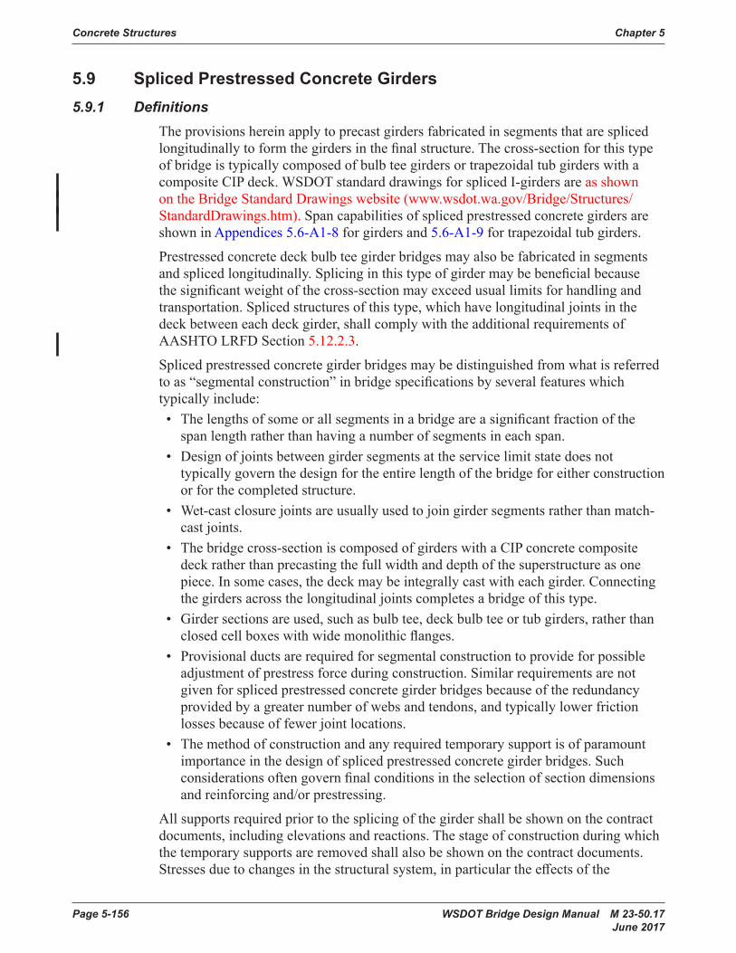
Concrete Structures Chapter 5
Page 5-156 WSDOT Bridge Design Manual M 23-50.17 June 2017
5.9 Spliced Prestressed Concrete Girders5.9.1 Definitions
Theprovisionshereinapplytoprecastgirdersfabricatedinsegmentsthataresplicedlongitudinallytoformthegirdersinthefinalstructure.Thecross-sectionforthistypeofbridgeistypicallycomposedofbulbteegirdersortrapezoidaltubgirderswithacomposite CIP deck. WSDOT standard drawings for spliced I-girders are as shown ontheBridgeStandardDrawingswebsite(www.wsdot.wa.gov/Bridge/Structures/StandardDrawings.htm). Spancapabilitiesofsplicedprestressedconcretegirdersareshown in Appendices 5.6-A1-8 for girders and 5.6-A1-9fortrapezoidaltubgirders.
Prestressedconcretedeckbulbteegirderbridgesmayalsobefabricatedinsegmentsandsplicedlongitudinally.Splicinginthistypeofgirdermaybebeneficialbecausethesignificantweightofthecross-sectionmayexceedusuallimitsforhandlingandtransportation. Spliced structures of this type, which have longitudinal joints in the deckbetweeneachdeckgirder,shallcomplywiththeadditionalrequirementsofAASHTO LRFD Section 5.12.2.3.
Splicedprestressedconcretegirderbridgesmaybedistinguishedfromwhatisreferredtoas“segmentalconstruction”inbridgespecificationsbyseveralfeatureswhichtypicallyinclude:• Thelengthsofsomeorallsegmentsinabridgeareasignificantfractionofthespanlengthratherthanhavinganumberofsegmentsineachspan.
• Designofjointsbetweengirdersegmentsattheservicelimitstatedoesnottypicallygovernthedesignfortheentirelengthofthebridgeforeitherconstructionor for the completed structure.
• Wet-cast closure joints are usually used to join girder segments rather than match-cast joints.
• Thebridgecross-sectioniscomposedofgirderswithaCIPconcretecompositedeck rather than precasting the full width and depth of the superstructure as one piece.Insomecases,thedeckmaybeintegrallycastwitheachgirder.Connectingthegirdersacrossthelongitudinaljointscompletesabridgeofthistype.
• Girdersectionsareused,suchasbulbtee,deckbulbteeortubgirders,ratherthanclosedcellboxeswithwidemonolithicflanges.
• Provisionalductsarerequiredforsegmentalconstructiontoprovideforpossibleadjustment of prestress force during construction. Similar requirements are not givenforsplicedprestressedconcretegirderbridgesbecauseoftheredundancyprovidedbyagreaternumberofwebsandtendons,andtypicallylowerfrictionlossesbecauseoffewerjointlocations.
• The method of construction and any required temporary support is of paramount importanceinthedesignofsplicedprestressedconcretegirderbridges.Suchconsiderationsoftengovernfinalconditionsintheselectionofsectiondimensionsand reinforcing and/or prestressing.
Allsupportsrequiredpriortothesplicingofthegirdershallbeshownonthecontractdocuments, including elevations and reactions. The stage of construction during which thetemporarysupportsareremovedshallalsobeshownonthecontractdocuments.Stressesduetochangesinthestructuralsystem,inparticulartheeffectsofthe
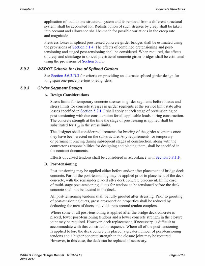
Chapter 5 Concrete Structures
WSDOT Bridge Design Manual M 23-50.17 Page 5-157 June 2017
applicationofloadtoonestructuralsystemanditsremovalfromadifferentstructuralsystem,shallbeaccountedfor.Redistributionofsuchstressesbycreepshallbetakenintoaccountandallowanceshallbemadeforpossiblevariationsinthecreeprateand magnitude.
Prestresslossesinsplicedprestressedconcretegirderbridgesshallbeestimatedusingthe provisions of Section 5.1.4.Theeffectsofcombinedpretensioningandpost-tensioningandstagedpost-tensioningshallbeconsidered.Whenrequired,theeffectsofcreepandshrinkageinsplicedprestressedconcretegirderbridgesshallbeestimatedusing the provisions of Section 5.1.1.
5.9.2 WSDOT Criteria for Use of Spliced GirdersSee Section 5.6.3.D.3 for criteria on providing an alternate spliced-girder design for long span one-piece pre-tensioned girders.
5.9.3 Girder Segment DesignA. Design Considerations
Stresslimitsfortemporaryconcretestressesingirdersegmentsbeforelossesandstress limits for concrete stresses in girder segments at the service limit state after lossesspecifiedinSection 5.2.1.C shall apply at each stage of pretensioning or post-tensioningwithdueconsiderationforallapplicableloadsduringconstruction.Theconcretestrengthatthetimethestageofprestressingisappliedshallbesubstitutedforƒ′ci in the stress limits.
Thedesignershallconsiderrequirementsforbracingofthegirdersegmentsoncetheyhavebeenerectedonthesubstructure.Anyrequirementsfortemporaryorpermanentbracingduringsubsequentstagesofconstruction,alongwiththecontractor’sresponsibilitiesfordesigningandplacingthem,shallbespecifiedinthe contract documents.
EffectsofcurvedtendonsshallbeconsideredinaccordancewithSection 5.8.1.F.
B. Post-tensioning
Post-tensioningmaybeappliedeitherbeforeand/orafterplacementofbridgedeckconcrete.Partofthepost-tensioningmaybeappliedpriortoplacementofthedeckconcrete, with the remainder placed after deck concrete placement. In the case ofmulti-stagepost-tensioning,ductsfortendonstobetensionedbeforethedeckconcreteshallnotbelocatedinthedeck.
Allpost-tensioningtendonsshallbefullygroutedafterstressing.Priortogroutingofpost-tensioningducts,grosscross-sectionpropertiesshallbereducedbydeducting the area of ducts and void areas around tendon couplers.
Wheresomeorallpost-tensioningisappliedafterthebridgedeckconcreteisplaced, fewer post-tensioning tendons and a lower concrete strength in the closure jointmayberequired.However,deckreplacement,ifnecessary,isdifficulttoaccommodate with this construction sequence. Where all of the post-tensioning isappliedbeforethedeckconcreteisplaced,agreaternumberofpost-tensioningtendonsandahigherconcretestrengthintheclosurejointmayberequired.However,inthiscase,thedeckcanbereplacedifnecessary.

Concrete Structures Chapter 5
Page 5-158 WSDOT Bridge Design Manual M 23-50.17 June 2017
5.9.4 Joints Between SegmentsA. General
Cast-in-place closure joints are typically used in spliced girder construction. Thesequenceofplacingconcretefortheclosurejointsandbridgedeckshallbespecifiedinthecontractdocuments.Match-castjointsshallnotbespecifiedforsplicedgirderbridgesunlessapprovedbytheBridgeDesignEngineer.Prestress,deadload,andcreepeffectsmaycauserotationofthefacesofthematch-castjointspriortosplicing.Ifmatchcastjointisspecified,theproceduresforsplicingthegirdersegmentsthatovercomethisrotationtoclosethematch-castjointshallbeshown on the contract plans.
B. Location of Closure Joints
Thelocationofintermediatediaphragmsshallbeoffsetbyatleast2′-0″fromtheedge of cast-in-place closure joints.
Inhorizontallycurvedsplicedgirderbridges,intermediatediaphragmscouldbelocatedattheCIPclosurejointsifstraightsegmentsaresplicedwithdeflectionpointsatclosures.Inthiscase,thediaphragmcouldbeextendedbeyondthefaceofthe exterior girder for improved development of diaphragm reinforcement.
ThefinalconfigurationoftheclosuresshallbecoordinatedwiththeStateBridgeandStructuresArchitectonallhighlyvisiblebridges,suchasbridgesovervehicularorpedestriantraffic.
C. Details of Closure Joints
Thelengthofaclosurejointbetweenconcretesegmentsshallallowforthesplicingofsteelwhosecontinuityisrequiredbydesignconsiderationsandtheaccommodation of the splicing of post-tensioning ducts. The length of a closure jointshallnotbelessthan2′-0″.Alongerclosurejointmaybeusedtoprovidemore room to accommodate tolerances for potential misalignment of ducts within girder segments and misalignment of girder segments at erection.
Webreinforcementwithinthejointshallbethelargerofthatintheadjacentgirders.Thefaceofthesegmentsatclosurejointsshallbespecifiedasintentionallyroughened surface.
ConcretecovertowebstirrupsattheCIPclosuresofpierdiaphragmsshallnotbelessthan2½″.IfintermediatediaphragmlocationscoincidewithCIPclosuresbetweensegments,thentheconcretecoverattheCIPclosuresshallnotbelessthan2½″.Thisincreaseinconcretecoverisnotnecessaryifintermediatediaphragmlocations are away from the CIP closures. See Figures 5.9.4-1 to 5.9.4-3 for details of closure joints.
AdequatereinforcementshallbeprovidedtoconfinetendonsatCIPclosuresandatintermediatepierdiaphragms.Thereinforcementshallbeproportionedtoensurethat the steel stress during the jacking operation does not exceed 0.6fy.
TheclearspacingbetweenductsatCIPclosuresofpierdiaphragmsshallbe2.0″minimum. The duct diameter for WSDOT standard spliced girders shall not exceed 4.0″forsplicedI-girdersand4½″forsplicedtubgirders.

Chapter 5 Concrete Structures
WSDOT Bridge Design Manual M 23-50.17 Page 5-159 June 2017
On the construction sequence sheet indicate that the side forms at the CIP closures andintermediatepierdiaphragmsshallberemovedtoinspectforconcreteconsolidation prior to post-tensioning and grouting.
Self-consolidatingconcrete(SCC)maybeusedforCIPclosures.
D. Joint Design
StresslimitsfortemporaryconcretestressesinjointsbeforelossesspecifiedinSection 5.2.1.C shall apply at each stage of post-tensioning. The concrete strength atthetimethestageofpost-tensioningisappliedshallbesubstitutedforƒ′ci in the stress limits.
Stress limits for concrete stresses in joints at the service limit state after losses specifiedinSection 5.2.1.C shall apply. These stress limits shall also apply for intermediate load stages, with the concrete strength at the time of loading substitutedforƒ′c in the stress limits. The compressive strength of the closure joint concreteataspecifiedageshallbecompatiblewithdesignstresslimitations.

Concrete Structures Chapter 5
Page 5-160 WSDOT Bridge Design Manual M 23-50.17 June 2017
¢ PIER
¢PRECAST
TRAPEZOIDAL
TUB
GIRDER
2" #5 @ 4" SPA. 2"
2½" CLR.(TYP.)
END OF PRECASTSEGMENT
FACE OFDIAPHRAGM
DIAPHRAGMREINFORCING
POST-TENSIONINGDUCT (TYP.)
INTERIOR WEB
EXTERIOR WEB45° FILLET(TYP.)
CIP Closure at Pier DiaphragmFigure 5.9.4-1
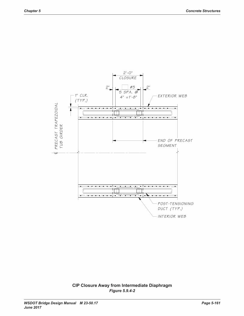
Chapter 5 Concrete Structures
WSDOT Bridge Design Manual M 23-50.17 Page 5-161 June 2017
¢PRECAST
TRAPEZOIDAL
TUB
GIRDER
2" 2"#55 SPA. @4" =1'-8"
2'-0"CLOSURE
1" CLR.(TYP.)
END OF PRECASTSEGMENT
INTERIOR WEB
EXTERIOR WEB
POST-TENSIONINGDUCT (TYP.)
CIP Closure Away from Intermediate DiaphragmFigure 5.9.4-2
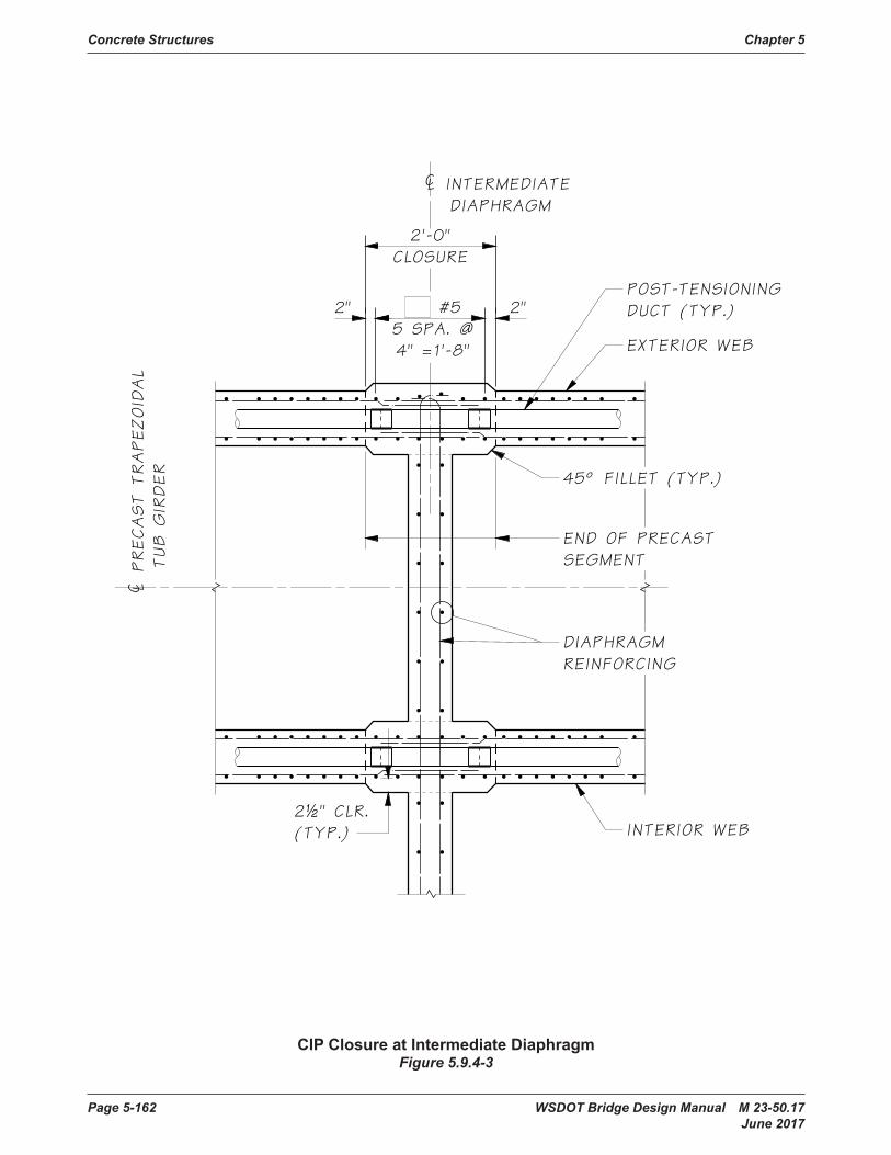
Concrete Structures Chapter 5
Page 5-162 WSDOT Bridge Design Manual M 23-50.17 June 2017
¢ INTERMEDIATEDIAPHRAGM
¢PRECAST
TRAPEZOIDAL
TUB
GIRDER
2" 2"#55 SPA. @4" =1'-8"
2'-0"CLOSURE
2½" CLR.(TYP.)
45° FILLET (TYP.)
END OF PRECASTSEGMENT
POST-TENSIONINGDUCT (TYP.)
DIAPHRAGMREINFORCING
INTERIOR WEB
EXTERIOR WEB
CIP Closure at Intermediate DiaphragmFigure 5.9.4-3

Chapter 5 Concrete Structures
WSDOT Bridge Design Manual M 23-50.17 Page 5-163 June 2017
5.9.5 Review of Shop Plans for Spliced Prestressed Concrete GirdersShopdrawingsforsplicedprestressedconcretegirdersshallbereviewedbythedesigner(orBridgeTechnicalAdvisorfornon-BridgeOfficeprojects)andconsultedwiththeConcreteSpecialistifneeded.Reviewofshopdrawingshallinclude:
1. Allprestressingstrandsshallbeof½″or0.6″diametergrade270lowrelaxationuncoated strands.
2. Numberofstrandspersegment.
3. Pretensioningstrandsjackingstressesshallnotexceed0.75ƒpu.
4. Strand placement patterns.
5. Temporarystrandplacementpatterns,locationandsizeofblockoutsforcutting strands.
6. Procedureforcuttingtemporarystrandsandpatchingtheblockoutsshallbespecified.
7. Numberandlengthofextendedstrandsandrebarsatgirderends.
8. Location of holes and shear keys for intermediate and end diaphragms.
9. Locationandsizeofbearingrecesses.
10. Saw tooth at girder ends.
11.Locationandsizeofliftingloopsorliftingbars.
12.Numberandsizeofhorizontalandverticalreinforcement.
13. Segment length and end skew.
14.Tendonprofileandtendonplacementpattern.
15.Ductsizeshallbebasedontheductareaatleast2.5timesthetotalareaofprestressing strands.
16.Anchorset.Thepost-tensioningdesignistypicallybasedonananchorsetof⅜″.
17.Maximumnumberofstrandspertendonshallnotexceed(37)½″diameterstrandsor(27)0.6″diameterstrandsperStandard Specifications Section 6-02.3(26)F.
18. Jacking force per girder.
19.Prestressforceafteranchorset(lift-offforce).
20.Numberofstrandsperweb.
21. Anchorage system shall conform to pre-approved list of post-tensioning system per Appendix 5-B4.Theanchorageassemblydimensionsandreinforcementdetailingshall conform to the corresponding post-tensioning catalog.
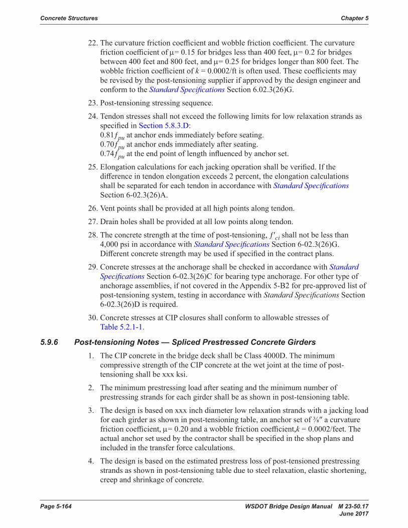
Concrete Structures Chapter 5
Page 5-164 WSDOT Bridge Design Manual M 23-50.17 June 2017
22.Thecurvaturefrictioncoefficientandwobblefrictioncoefficient.Thecurvaturefrictioncoefficientofμ=0.15forbridgeslessthan400feet,μ=0.2forbridgesbetween400feetand800feet,andμ=0.25forbridgeslongerthan800feet.Thewobblefrictioncoefficientofk=0.0002/ftisoftenused.Thesecoefficientsmayberevisedbythepost-tensioningsupplierifapprovedbythedesignengineerandconform to the Standard Specifications Section 6.02.3(26)G.
23. Post-tensioning stressing sequence.
24. Tendon stresses shall not exceed the following limits for low relaxation strands as specifiedinSection 5.8.3.D: 0.81ƒpuatanchorendsimmediatelybeforeseating. 0.70ƒpu at anchor ends immediately after seating. 0.74ƒpuattheendpointoflengthinfluencedbyanchorset.
25.Elongationcalculationsforeachjackingoperationshallbeverified.Ifthedifferenceintendonelongationexceeds2percent,theelongationcalculationsshallbeseparatedforeachtendoninaccordancewithStandard Specifications Section 6-02.3(26)A.
26.Ventpointsshallbeprovidedatallhighpointsalongtendon.
27.Drainholesshallbeprovidedatalllowpointsalongtendon.
28.Theconcretestrengthatthetimeofpost-tensioning,ƒ′cishallnotbelessthan4,000 psi in accordance with Standard Specifications Section 6-02.3(26)G. Differentconcretestrengthmaybeusedifspecifiedinthecontractplans.
29.ConcretestressesattheanchorageshallbecheckedinaccordancewithStandard SpecificationsSection6-02.3(26)Cforbearingtypeanchorage.Forothertypeofanchorageassemblies,ifnotcoveredintheAppendix5-B2forpre-approvedlistofpost-tensioning system, testing in accordance with Standard Specifications Section 6-02.3(26)D is required.
30.ConcretestressesatCIPclosuresshallconformtoallowablestressesofTable5.2.1-1.
5.9.6 Post-tensioning Notes — Spliced Prestressed Concrete Girders1. TheCIPconcreteinthebridgedeckshallbeClass4000D.Theminimum
compressive strength of the CIP concrete at the wet joint at the time of post-tensioningshallbexxxksi.
2. Theminimumprestressingloadafterseatingandtheminimumnumberofprestressingstrandsforeachgirdershallbeasshowninpost-tensioningtable.
3. Thedesignisbasedonxxxinchdiameterlowrelaxationstrandswithajackingloadforeachgirderasshowninpost-tensioningtable,ananchorsetof⅜″acurvaturefrictioncoefficient,μ=0.20andawobblefrictioncoefficient,k = 0.0002/feet. The actualanchorsetusedbythecontractorshallbespecifiedintheshopplansandincluded in the transfer force calculations.
4. Thedesignisbasedontheestimatedprestresslossofpost-tensionedprestressingstrandsasshowninpost-tensioningtableduetosteelrelaxation,elasticshortening,creep and shrinkage of concrete.

Chapter 5 Concrete Structures
WSDOT Bridge Design Manual M 23-50.17 Page 5-165 June 2017
5. Thecontractorshallsubmitthestressingsequenceandelongationcalculationstothe engineer for approval. All losses due to tendon vertical and horizontal curvature mustbeincludedinelongationcalculations.Thestressingsequenceshallmeetthefollowingcriteria:
A. Theprestressingforceshallbedistributedwithanapproximatelyequalamountineachwebandshallbeplacedsymmetricallyaboutthecenterlineofthebridge.
B. Nomorethanone-halfoftheprestressingforceinanywebmaybestressedbeforeanequalforceisstressedintheadjacentwebs.Atnotimeduringstressing operation will more than one-sixth of the total prestressing force isappliedeccentricallyaboutthecenterlineofbridge.
6. Themaximumoutsidediameteroftheductshallbexxxinches.Theareaoftheductshallbeatleast2.5timesthenetareaoftheprestressingsteelintheduct.
7. Alltendonsshallbestressedfrompiernumberxxx.
Concrete Structures Chapter 5
Page 5-166 WSDOT Bridge Design Manual M 23-50.17 June 2017
5.10 Bridge Standard DrawingsGirder Sections
5.6-A1-10 Prestressed Concrete I and WF Girders
5.6-A1-11 Prestressed Concrete Deck Girders
5.6-A1-12 Spliced Prestressed Concrete Girders
5.6-A1-13 PrestressedConcreteTubGirders
Superstructure Construction Sequences5.6-A2-1 Single Span Prestressed Girder Construction Sequence
5.6-A2-2 Multiple Span Prestressed Girder Construction Sequence
5.6-A2-3 RaisedCrossbeamPrestressedGirderConstructionSequence
W Girders5.6-A3-1 W42G Girder Details 1 of 2
5.6-A3-2 W42G Girder Details 2 of 2
5.6-A3-3 W50G Girder Details 1 of 2
5.6-A3-4 W50G Girder Details 2 of 2
5.6-A3-5 W58G Girder Details 1 of 3
5.6-A3-6 W58G Girder Details 2 of 3
5.6-A3-7 W58G Girder Details 3 of 3
5.6-A3-8 W74G Girder Details 1 of 3
5.6-A3-9 W74G Girder Details 2 of 3
5.6-A3-10 W74G Girder Details 3 of 3
WF Girders5.6-A4-1 WF Girder Details 1 of 5
5.6-A4-2 WF Girder Details 2 of 5
5.6-A4-3 WF Girder Details 3 of 5
5.6-A4-4 WF Girder Details 4 of 5
5.6-A4-5 WF Girder Details 5 of 5
5.6-A4-6 Additional Extended Strands
5.6-A4-7 End Diaphragm Details
5.6-A4-8 LAbutmentEndDiaphragmDetails
5.6-A4-9 Diaphragm at Intermediate Pier Details
5.6-A4-10 Partial Depth Intermediate Diaphragm Details
5.6-A4-11 Full Depth Intermediate Diaphragm Details
5.6-A4-12 I Girder Bearing Details

Chapter 5 Concrete Structures
WSDOT Bridge Design Manual M 23-50.17 Page 5-167 June 2017
Wide Flange Thin Deck Girders5.6-A5-1 WF Thin Deck Girder Details 1 of 5
5.6-A5-2 WF Thin Deck Girder Details 2 of 5
5.6-A5-3 WF Thin Deck Girder Details 3 of 5
5.6-A5-4 WF Thin Deck Girder Details 4 of 5
5.6-A5-5 WF Thin Deck Girder Details 5 of 5
5.6-A5-6 WF Thin Deck Girder End Diaphragm Details
5.6-A5-7 WFThinDeckGirderLAbutmentEndDiaphragmDetails
5.6-A5-8 WF Thin Deck Girder Diaphragm at Intermediate Pier Details
5.6-A5-9 WF Thin Deck Girder Partial Depth Intermed. Diaphragm
5.6-A5-10 WF Thin Deck Girder Full Depth Intermediate Diaphragm
Wide Flange Deck Girders5.6-A6-1 WF Deck Girder Details 1 of 4
5.6-A6-2 WF Deck Girder Details 2 of 4
5.6-A6-3 WF Deck Girder Details 3 of 4
5.6-A6-4 WF Deck Girder Details 4 of 4
5.6-A6-5 WF Deck Girder End Diaphragm Details
5.6-A6-6 WFDeckGirderLAbutmentEndDiaphragmDetails
5.6-A6-7 WF Deck Girder Diaphragm at Intermediate Pier Details
5.6-A6-8 WF Deck Girder Full Depth Intermediate Diaphragm
Deck Bulb Tee Girders5.6-A7-1 DeckBulbTeeGirderSchedule
5.6-A7-2 DeckBulbTeeGirderDetails1of2
5.6-A7-3 DeckBulbTeeGirderDetails2of2
Slabs5.6-A8-1 SlabGirderDetails1of3
5.6-A8-2 SlabGirderDetails2of3
5.6-A8-3 SlabGirderDetails3of3
5.6-A8-5 SlabGirderFixedDiaphragm
5.6-A8-6 SlabGirderEndDiaphragm

Concrete Structures Chapter 5
Page 5-168 WSDOT Bridge Design Manual M 23-50.17 June 2017
Tub Girders5.6-A9-1 TubGirderScheduleandNotes
5.6-A9-2 TubGirderDetails1of3
5.6-A9-3 TubGirderDetails2of3
5.6-A9-4 TubGirderDetails3of3
5.6-A9-5 TubGirderEndDiaphragmonGirderDetails
5.6-A9-6 TubGirderRaisedCrossbeamDetails
5.6-A9-7 TubS-I-PDeckPanelGirder–EndDiaphragmonGirderDetails
5.6-A9-8 TubS-I-PDeckPanelGirder–RaisedCrossbeamDetails
5.6-A9-9 TubGirderBearingDetails
Stay-In-Place Deck Panel5.6-A10-1 Stay-In-Place (SIP) Deck Panel Details
Post Tensioned Spliced Girders5.9-A1-1 WF74PTG Spliced Girder Details 1 of 5
5.9-A1-2 WF74PTG Spliced Girder Details 2 of 5
5.9-A1-3 Spliced Girder Details 3 of 5
5.9-A1-4 WF74PTG Girder Details 4 of 5
5.9-A1-5 Spliced Girder Details 5 of 5
5.9-A2-1 WF83PTG Spliced Girder Details 1 of 5
5.9-A2-2 WF83PTG Spliced Girder Details 2 of 5
5.9-A2-4 WF83PTG Spliced Girder Details 4 of 5
5.9-A3-1 WF95PTG Spliced Girder Details 1 of 5
5.9-A3-2 WF95PTG Spliced Girder Details 2 of 5
5.9-A3-4 WF95PTG Spliced Girder Details 4 of 5
5.9-A4-1 TrapezoidalTubGirderBearingDetails
5.9-A4-2 TubSplicedGirderDetails1of5
5.9-A4-3 TubSplicedGirderDetails2of5
5.9-A4-4 TubSplicedGirderDetails3of5
5.9-A4-5 TubSplicedGirderDetails4of5
5.9-A4-6 TubSplicedGirderDetails5of5
5.9-A4-7 TubSplicedGirderEndDiaphragmonGirderDetails
5.9-A4-8 TubSplicedGirderRaisedCrossbeamDetails

Chapter 5 Concrete Structures
WSDOT Bridge Design Manual M 23-50.17 Page 5-169 June 2017
5.9-A5-1 P.T.TrapezoidalTubS-I-PDeckPanelSplicedGirderDetails1of5
5.9-A5-2 P.T.TrapezoidalTubS-I-PDeckPanelSplicedGirder–Details2of5
5.9-A5-3 P.T.TrapezoidalTubS-I-PDeckPanelSplicedGirder–Details3of5
5.9-A5-4 P.T.TrapezoidalTubS-I-PDeckPanelSplicedGirder–Details4of5
5.9-A5-5 P.T.TrapezoidalTubS-I-PDeckPanelSplicedGirder–Details5of5
5.9-A5-6 TrapezoidalTubS-I-PDeckPanelGirder–EndDiaphragmonGirder Details
5.9-A5-7 TrapezoidalTubS-I-PDeckPanelGirder–RaisedCrossbeamDetails
Concrete Structures Chapter 5
Page 5-170 WSDOT Bridge Design Manual M 23-50.17 June 2017
5.11 AppendicesAppendix 5.1-A1 Standard Hooks
Appendix 5.1-A2 Minimum Reinforcement Clearance and Spacing for Beams and Columns
Appendix 5.1-A3 Reinforcing Bar Properties
Appendix 5.1-A4 Tension Development Length of Deformed Bars
Appendix 5.1-A5 Compression Development Length and Minimum Lap Splice of Grade 60 Bars
Appendix 5.1-A6 Tension Development Length of 90º and 180º Standard Hooks
Appendix 5.1-A7 Tension Lap Splice Lengths of Grade 60 Bars – Class B
Appendix 5.1-A8 Prestressing Strand Properties and Development Length
Appendix 5.2-A1 Working Stress Design
Appendix 5.2-A2 Working Stress Design
Appendix 5.2-A3 Working Stress Design
Appendix 5.3-A1 Positive Moment Reinforcement
Appendix 5.3-A2 Negative Moment Reinforcement
Appendix 5.3-A3 Adjusted Negative Moment Case I (Design for M at Face of Support)
Appendix 5.3-A4 Adjusted Negative Moment Case II (Design for M at 1/4 Point)
Appendix 5.3-A5 Cast-In-PlaceDeckSlabDesignforPositiveMomentRegionsƒ′c = 4.0 ksi
Appendix 5.3-A6 Cast-In-PlaceDeckSlabDesignforNegativeMomentRegionsƒ′c = 4.0 ksi
Appendix 5.3-A7 SlabOverhangDesign-InteriorBarrierSegment
Appendix 5.3-A8 SlabOverhangDesign-EndBarrierSegment
Appendix 5.6-A1-1 SpanCapabilityofWGirders
Appendix 5.6-A1-2 SpanCapabilityofWFGirders
Appendix 5.6-A1-3 SpanCapabilityofDeckBulbTeeGirders
Appendix 5.6-A1-4 SpanCapabilityofWFThinDeckGirders
Appendix 5.6-A1-5 SpanCapabilityofWFDeckGirders
Appendix 5.6-A1-6 SpanCapabilityofTrapezoidalTubGirderswithoutTopFlange
Appendix 5.6-A1-7 SpanCapabilityofTrapezoidalTubGirderswithTopFlange
Appendix 5.6-A1-8 SpanCapabilityofPost-tensionedSplicedI-Girders
Appendix 5.6-A1-9 SpanCapabilityofPost-tensionedSplicedTubGirders

Chapter 5 Concrete Structures
WSDOT Bridge Design Manual M 23-50.17 Page 5-171 June 2017
Appendix 5-B1 “A” Dimension for Precast Girder Bridges
Appendix 5-B2 Vacant
Appendix 5-B3 Existing Bridge Widenings
Appendix 5-B4 Post-tensioned Box Girder Bridges
Appendix 5-B5 Simple Span Prestressed Girder Design
Appendix 5-B6 Cast-in-PlaceSlabDesignExample
Appendix 5-B7 Precast Concrete Stay-in-place (SIP) Deck Panel
Appendix 5-B8 W35DGDeckBulbTee48"Wide
Appendix 5-B9 PrestressedVoidedSlabwithCast-in-PlaceTopping
Appendix 5-B10 Positive EQ Reinforcement at Interior Pier of a Prestressed Girder
Appendix 5-B11 LRFD Wingwall Design Vehicle Collision
Appendix 5-B12 Flexural Strength Calculations for Composite T-Beams
Appendix 5-B13 Strut-and-Tie Model Design Example for Hammerhead Pier
Appendix 5-B14 Shear and Torsion Capacity of a Reinforced Concrete Beam
Appendix 5-B15 Sound Wall Design – Type D-2k

Page 5-172 WSDOT Bridge Design Manual M 23-50.17 June 2017
Appendix 5.1-A1 Standard Hooks
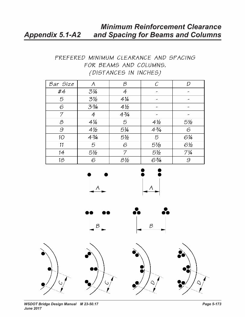
WSDOT Bridge Design Manual M 23-50.17 Page 5-173 June 2017
Minimum Reinforcement Clearance Appendix 5.1-A2 and Spacing for Beams and Columns
Bridge Design Manual M 23-50 Page 5.1-A2-1 August 2006
Minimum Reinforcement Clearance Appendix 5.1-A2 and Spacing for Beams and Columns
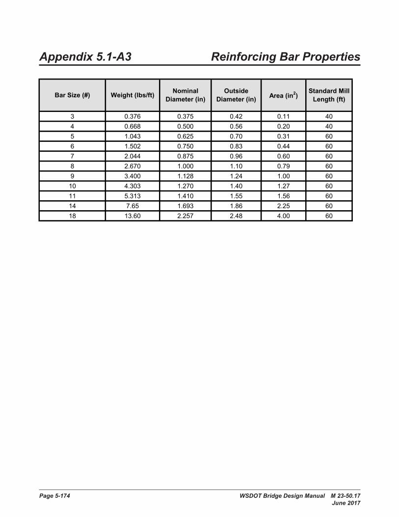
Page 5-174 WSDOT Bridge Design Manual M 23-50.17 June 2017
Appendix 5.1-A3 Reinforcing Bar PropertiesAppendix 5.1-A3 Reinforcing Bar Properties
3 0 .376 0 .375 0 .42 0 .11 404 0 .668 0 .500 0 .56 0 .20 405 1 .043 0 .625 0 .70 0 .31 606 1 .502 0 .750 0 .83 0 .44 607 2 .044 0 .875 0 .96 0 .60 608 2 .670 1 .000 1 .10 0 .79 609 3 .400 1 .128 1 .24 1 .00 6010 4 .303 1 .270 1 .40 1 .27 6011 5 .313 1 .410 1 .55 1 .56 6014 7 .65 1 .693 1 .86 2 .25 6018 13 .60 2 .257 2 .48 4 .00 60
Bar Size (#) Nominal Diameter (in)
Outside Diameter (in) Area (in2)
Standard Mill Length (ft)Weight (lbs/ft)
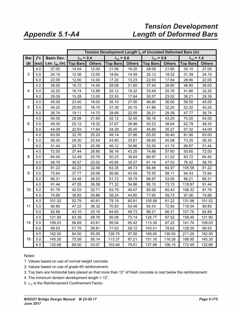
WSDOT Bridge Design Manual M 23-50.17 Page 5-175 June 2017
Tension Development Appendix 5.1-A4 Length of Deformed BarsAppendix 5.1-A4 Tension Development
Length of Deformed Bars
Bar ƒ′c Basic Dev. λrc = 0.4 λrc = 0.6 λrc = 0.8 λrc = 1.0(#) (ksi) Len. ldb (in) Top Bars Others Top Bars Others Top Bars Others Top Bars Others
4 .0 27 .00 14 .04 12 .00 21 .06 16 .20 28 .08 21 .60 35 .10 27 .005 .0 24 .15 12 .56 12 .00 18 .84 14 .49 25 .12 19 .32 31 .39 24 .156 .0 22 .05 12 .00 12 .00 17 .20 13 .23 22 .93 17 .64 28 .66 22 .054 .0 36 .00 18 .72 14 .40 28 .08 21 .60 37 .44 28 .80 46 .80 36 .005 .0 32 .20 16 .74 12 .88 25 .12 19 .32 33 .49 25 .76 41 .86 32 .206 .0 29 .39 15 .28 12 .00 22 .93 17 .64 30 .57 23 .52 38 .21 29 .394 .0 45 .00 23 .40 18 .00 35 .10 27 .00 46 .80 36 .00 58 .50 45 .005 .0 40 .25 20 .93 16 .10 31 .39 24 .15 41 .86 32 .20 52 .32 40 .256 .0 36 .74 19 .11 14 .70 28 .66 22 .05 38 .21 29 .39 47 .77 36 .744 .0 54 .00 28 .08 21 .60 42 .12 32 .40 56 .16 43 .20 70 .20 54 .005 .0 48 .30 25 .12 19 .32 37 .67 28 .98 50 .23 38 .64 62 .79 48 .306 .0 44 .09 22 .93 17 .64 34 .39 26 .45 45 .85 35 .27 57 .32 44 .094 .0 63 .00 32 .76 25 .20 49 .14 37 .80 65 .52 50 .40 81 .90 63 .005 .0 56 .35 29 .30 22 .54 43 .95 33 .81 58 .60 45 .08 73 .25 56 .356 .0 51 .44 26 .75 20 .58 40 .12 30 .86 53 .50 41 .15 66 .87 51 .444 .0 72 .00 37 .44 28 .80 56 .16 43 .20 74 .88 57 .60 93 .60 72 .005 .0 64 .40 33 .49 25 .76 50 .23 38 .64 66 .97 51 .52 83 .72 64 .406 .0 58 .79 30 .57 23 .52 45 .85 35 .27 61 .14 47 .03 76 .42 58 .794 .0 81 .22 42 .23 32 .49 63 .35 48 .73 84 .46 64 .97 105 .58 81 .225 .0 72 .64 37 .77 29 .06 56 .66 43 .59 75 .55 58 .11 94 .43 72 .646 .0 66 .31 34 .48 26 .53 51 .72 39 .79 68 .97 53 .05 86 .21 66 .314 .0 91 .44 47 .55 36 .58 71 .32 54 .86 95 .10 73 .15 118 .87 91 .445 .0 81 .79 42 .53 32 .71 63 .79 49 .07 85 .06 65 .43 106 .32 81 .796 .0 74 .66 38 .82 29 .86 58 .24 44 .80 77 .65 59 .73 97 .06 74 .664 .0 101 .52 52 .79 40 .61 79 .19 60 .91 105 .58 81 .22 131 .98 101 .525 .0 90 .80 47 .22 36 .32 70 .83 54 .48 94 .43 72 .64 118 .04 90 .806 .0 82 .89 43 .10 33 .16 64 .65 49 .73 86 .21 66 .31 107 .76 82 .894 .0 121 .90 63 .39 48 .76 95 .08 73 .14 126 .77 97 .52 158 .46 121 .905 .0 109 .03 56 .69 43 .61 85 .04 65 .42 113 .39 87 .22 141 .74 109 .036 .0 99 .53 51 .75 39 .81 77 .63 59 .72 103 .51 79 .62 129 .39 99 .534 .0 162 .50 84 .50 65 .00 126 .75 97 .50 169 .00 130 .00 211 .26 162 .505 .0 145 .35 75 .58 58 .14 113 .37 87 .21 151 .16 116 .28 188 .95 145 .356 .0 132 .68 69 .00 53 .07 103 .49 79 .61 137 .99 106 .15 172 .49 132 .68
Notes:1. Values based on use of normal weight concrete.2. Values based on use of grade 60 reinforcement.3. Top bars are horizontal bars placed so that more than 12” of fresh concrete is cast below the reinforcement.4. The minimum tension development length = 12”.5 . λrc is the Reinforcement Confinement Factor .
9
10
11
14
18
7
8
Tension Development Length ld of Uncoated Deformed Bars (in)
3
4
5
6
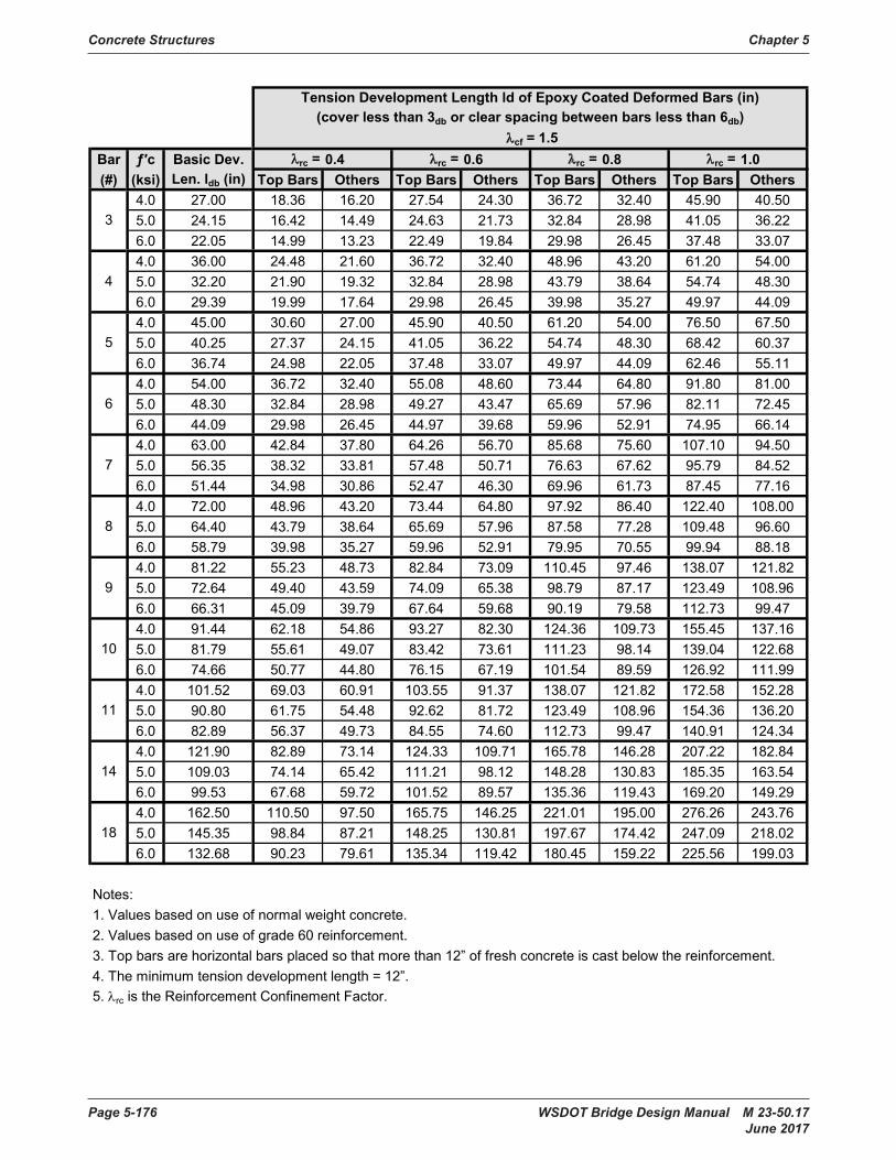
Concrete Structures Chapter 5
Page 5-176 WSDOT Bridge Design Manual M 23-50.17 June 2017
Bar ƒ′c Basic Dev. λrc = 0.4 λrc = 0.6 λrc = 0.8 λrc = 1.0(#) (ksi) Len. ldb (in) Top Bars Others Top Bars Others Top Bars Others Top Bars Others
4 .0 27 .00 18 .36 16 .20 27 .54 24 .30 36 .72 32 .40 45 .90 40 .505 .0 24 .15 16 .42 14 .49 24 .63 21 .73 32 .84 28 .98 41 .05 36 .226 .0 22 .05 14 .99 13 .23 22 .49 19 .84 29 .98 26 .45 37 .48 33 .074 .0 36 .00 24 .48 21 .60 36 .72 32 .40 48 .96 43 .20 61 .20 54 .005 .0 32 .20 21 .90 19 .32 32 .84 28 .98 43 .79 38 .64 54 .74 48 .306 .0 29 .39 19 .99 17 .64 29 .98 26 .45 39 .98 35 .27 49 .97 44 .094 .0 45 .00 30 .60 27 .00 45 .90 40 .50 61 .20 54 .00 76 .50 67 .505 .0 40 .25 27 .37 24 .15 41 .05 36 .22 54 .74 48 .30 68 .42 60 .376 .0 36 .74 24 .98 22 .05 37 .48 33 .07 49 .97 44 .09 62 .46 55 .114 .0 54 .00 36 .72 32 .40 55 .08 48 .60 73 .44 64 .80 91 .80 81 .005 .0 48 .30 32 .84 28 .98 49 .27 43 .47 65 .69 57 .96 82 .11 72 .456 .0 44 .09 29 .98 26 .45 44 .97 39 .68 59 .96 52 .91 74 .95 66 .144 .0 63 .00 42 .84 37 .80 64 .26 56 .70 85 .68 75 .60 107 .10 94 .505 .0 56 .35 38 .32 33 .81 57 .48 50 .71 76 .63 67 .62 95 .79 84 .526 .0 51 .44 34 .98 30 .86 52 .47 46 .30 69 .96 61 .73 87 .45 77 .164 .0 72 .00 48 .96 43 .20 73 .44 64 .80 97 .92 86 .40 122 .40 108 .005 .0 64 .40 43 .79 38 .64 65 .69 57 .96 87 .58 77 .28 109 .48 96 .606 .0 58 .79 39 .98 35 .27 59 .96 52 .91 79 .95 70 .55 99 .94 88 .184 .0 81 .22 55 .23 48 .73 82 .84 73 .09 110 .45 97 .46 138 .07 121 .825 .0 72 .64 49 .40 43 .59 74 .09 65 .38 98 .79 87 .17 123 .49 108 .966 .0 66 .31 45 .09 39 .79 67 .64 59 .68 90 .19 79 .58 112 .73 99 .474 .0 91 .44 62 .18 54 .86 93 .27 82 .30 124 .36 109 .73 155 .45 137 .165 .0 81 .79 55 .61 49 .07 83 .42 73 .61 111 .23 98 .14 139 .04 122 .686 .0 74 .66 50 .77 44 .80 76 .15 67 .19 101 .54 89 .59 126 .92 111 .994 .0 101 .52 69 .03 60 .91 103 .55 91 .37 138 .07 121 .82 172 .58 152 .285 .0 90 .80 61 .75 54 .48 92 .62 81 .72 123 .49 108 .96 154 .36 136 .206 .0 82 .89 56 .37 49 .73 84 .55 74 .60 112 .73 99 .47 140 .91 124 .344 .0 121 .90 82 .89 73 .14 124 .33 109 .71 165 .78 146 .28 207 .22 182 .845 .0 109 .03 74 .14 65 .42 111 .21 98 .12 148 .28 130 .83 185 .35 163 .546 .0 99 .53 67 .68 59 .72 101 .52 89 .57 135 .36 119 .43 169 .20 149 .294 .0 162 .50 110 .50 97 .50 165 .75 146 .25 221 .01 195 .00 276 .26 243 .765 .0 145 .35 98 .84 87 .21 148 .25 130 .81 197 .67 174 .42 247 .09 218 .026 .0 132 .68 90 .23 79 .61 135 .34 119 .42 180 .45 159 .22 225 .56 199 .03
Notes:1. Values based on use of normal weight concrete.2. Values based on use of grade 60 reinforcement.3. Top bars are horizontal bars placed so that more than 12” of fresh concrete is cast below the reinforcement.4. The minimum tension development length = 12”.5 . λrc is the Reinforcement Confinement Factor .
Tension Development Length ld of Epoxy Coated Deformed Bars (in)(cover less than 3db or clear spacing between bars less than 6db)
18
λcf = 1.5
3
4
5
6
7
8
9
10
11
14

Chapter 5 Concrete Structures
WSDOT Bridge Design Manual M 23-50.17 Page 5-177 June 2017
Bar ƒ′c Basic Dev. λrc = 0.4 λrc = 0.6 λrc = 0.8 λrc = 1.0(#) (ksi) Len. ldb (in) Top Bars Others Top Bars Others Top Bars Others Top Bars Others
4 .0 27 .00 16 .85 12 .96 25 .27 19 .44 33 .70 25 .92 42 .12 32 .405 .0 24 .15 15 .07 12 .00 22 .60 17 .39 30 .14 23 .18 37 .67 28 .986 .0 22 .05 13 .76 12 .00 20 .63 15 .87 27 .51 21 .16 34 .39 26 .454 .0 36 .00 22 .46 17 .28 33 .70 25 .92 44 .93 34 .56 56 .16 43 .205 .0 32 .20 20 .09 15 .46 30 .14 23 .18 40 .18 30 .91 50 .23 38 .646 .0 29 .39 18 .34 14 .11 27 .51 21 .16 36 .68 28 .22 45 .85 35 .274 .0 45 .00 28 .08 21 .60 42 .12 32 .40 56 .16 43 .20 70 .20 54 .005 .0 40 .25 25 .12 19 .32 37 .67 28 .98 50 .23 38 .64 62 .79 48 .306 .0 36 .74 22 .93 17 .64 34 .39 26 .45 45 .85 35 .27 57 .32 44 .094 .0 54 .00 33 .70 25 .92 50 .54 38 .88 67 .39 51 .84 84 .24 64 .805 .0 48 .30 30 .14 23 .18 45 .21 34 .78 60 .28 46 .37 75 .35 57 .966 .0 44 .09 27 .51 21 .16 41 .27 31 .75 55 .03 42 .33 68 .78 52 .914 .0 63 .00 39 .31 30 .24 58 .97 45 .36 78 .62 60 .48 98 .28 75 .605 .0 56 .35 35 .16 27 .05 52 .74 40 .57 70 .32 54 .09 87 .90 67 .626 .0 51 .44 32 .10 24 .69 48 .15 37 .04 64 .20 49 .38 80 .25 61 .734 .0 72 .00 44 .93 34 .56 67 .39 51 .84 89 .86 69 .12 112 .32 86 .405 .0 64 .40 40 .18 30 .91 60 .28 46 .37 80 .37 61 .82 100 .46 77 .286 .0 58 .79 36 .68 28 .22 55 .03 42 .33 73 .37 56 .44 91 .71 70 .554 .0 81 .22 50 .68 38 .98 76 .02 58 .48 101 .36 77 .97 126 .70 97 .465 .0 72 .64 45 .33 34 .87 67 .99 52 .30 90 .66 69 .74 113 .32 87 .176 .0 66 .31 41 .38 31 .83 62 .07 47 .75 82 .76 63 .66 103 .45 79 .584 .0 91 .44 57 .06 43 .89 85 .59 65 .84 114 .12 87 .78 142 .65 109 .735 .0 81 .79 51 .03 39 .26 76 .55 58 .89 102 .07 78 .51 127 .59 98 .146 .0 74 .66 46 .59 35 .84 69 .88 53 .76 93 .18 71 .67 116 .47 89 .594 .0 101 .52 63 .35 48 .73 95 .02 73 .09 126 .70 97 .46 158 .37 121 .825 .0 90 .80 56 .66 43 .59 84 .99 65 .38 113 .32 87 .17 141 .65 108 .966 .0 82 .89 51 .72 39 .79 77 .59 59 .68 103 .45 79 .58 129 .31 99 .474 .0 121 .90 76 .06 58 .51 114 .09 87 .77 152 .13 117 .02 190 .16 146 .285 .0 109 .03 68 .03 52 .33 102 .05 78 .50 136 .07 104 .67 170 .08 130 .836 .0 99 .53 62 .11 47 .77 93 .16 71 .66 124 .21 95 .55 155 .26 119 .434 .0 162 .50 101 .40 78 .00 152 .10 117 .00 202 .80 156 .00 253 .51 195 .005 .0 145 .35 90 .70 69 .77 136 .05 104 .65 181 .39 139 .53 226 .74 174 .426 .0 132 .68 82 .79 63 .69 124 .19 95 .53 165 .59 127 .38 206 .99 159 .22
Notes:1. Values based on use of normal weight concrete.2. Values based on use of grade 60 reinforcement.3. Top bars are horizontal bars placed so that more than 12” of fresh concrete is cast below the reinforcement.4. The minimum tension development length = 12”.5 . λrc is the Reinforcement Confinement Factor .
11
14
18
Tension Development Length ld of Epoxy Coated Deformed Bars (in)
5
6
7
8
9
10
(cover not less than 3db and clear spacing between bars not less than 6db)λcf = 1.2
3
4
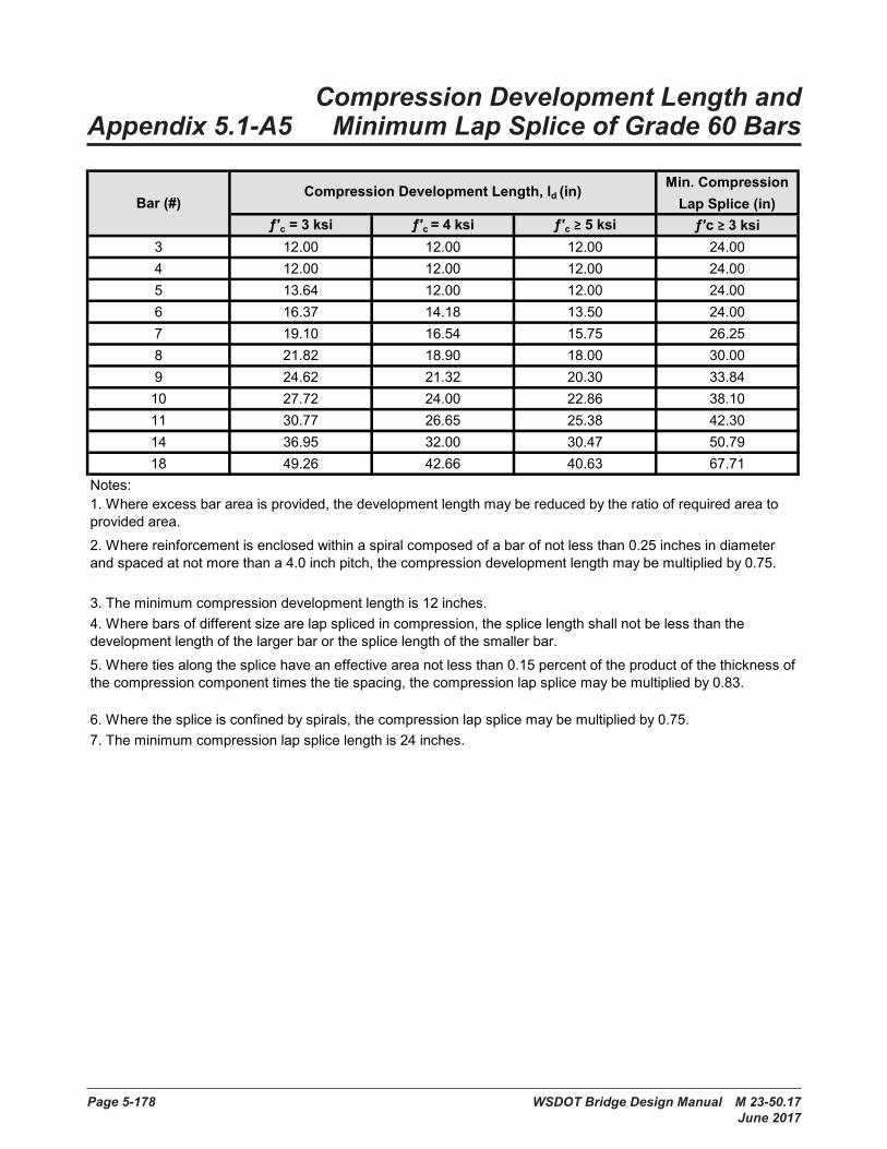
Page 5-178 WSDOT Bridge Design Manual M 23-50.17 June 2017
Compression Development Length and Appendix 5.1-A5 Minimum Lap Splice of Grade 60 Bars
Compression Development Length andAppendix 5.1-A5 Minimum Lap Splice of Grade 60 Bars
Min. CompressionLap Splice (in)
ƒ′c = 3 ksi ƒ′c = 4 ksi ƒ′c ≥ 5 ksi ƒ′c ≥ 3 ksi3 12 .00 12 .00 12 .00 24 .004 12 .00 12 .00 12 .00 24 .005 13 .64 12 .00 12 .00 24 .006 16 .37 14 .18 13 .50 24 .007 19 .10 16 .54 15 .75 26 .258 21 .82 18 .90 18 .00 30 .009 24 .62 21 .32 20 .30 33 .8410 27 .72 24 .00 22 .86 38 .1011 30 .77 26 .65 25 .38 42 .3014 36 .95 32 .00 30 .47 50 .7918 49 .26 42 .66 40 .63 67 .71
Notes:
7. The minimum compression lap splice length is 24 inches.
Bar (#)
6. Where the splice is confined by spirals, the compression lap splice may be multiplied by 0.75.
4. Where bars of different size are lap spliced in compression, the splice length shall not be less than the development length of the larger bar or the splice length of the smaller bar.5 . Where ties along the splice have an effective area not less than 0 .15 percent of the product of the thickness of the compression component times the tie spacing, the compression lap splice may be multiplied by 0.83.
Compression Development Length, ld (in)
2. Where reinforcement is enclosed within a spiral composed of a bar of not less than 0.25 inches in diameter and spaced at not more than a 4.0 inch pitch, the compression development length may be multiplied by 0.75.
3. The minimum compression development length is 12 inches.
1. Where excess bar area is provided, the development length may be reduced by the ratio of required area to provided area .

WSDOT Bridge Design Manual M 23-50.17 Page 5-179 June 2017
Tension Development Length Appendix 5.1-A6 of 90º and 180º Standard Hooks
Tension Development LengthAppendix 5.1-A6 of 90º and 180º Standard Hooks
4 7 .13 7 .13 6 .00 6 .00 6 .005 6 .37 6 .37 6 .00 6 .00 6 .006 5 .82 6 .00 6 .00 6 .00 6 .004 9 .50 9 .50 7 .60 7 .60 6 .085 8 .50 8 .50 6 .80 6 .80 6 .006 7 .76 7 .76 6 .21 6 .21 6 .004 11 .88 11 .88 9 .50 9 .50 7 .605 10 .62 10 .62 8 .50 8 .50 6 .806 9 .70 9 .70 7 .76 7 .76 6 .214 14 .25 14 .25 11 .40 11 .40 9 .125 12 .75 12 .75 10 .20 10 .20 8 .166 11 .64 11 .64 9 .31 9 .31 7 .454 16 .63 16 .63 13 .30 13 .30 10 .645 14 .87 14 .87 11 .90 11 .90 9 .526 13 .57 13 .57 10 .86 10 .86 8 .694 19 .00 19 .00 15 .20 15 .20 12 .165 16 .99 16 .99 13 .60 13 .60 10 .886 15 .51 15 .51 12 .41 12 .41 9 .934 21 .43 21 .43 17 .15 17 .15 13 .725 19 .17 19 .17 15 .34 15 .34 12 .276 17 .50 17 .50 14 .00 14 .00 11 .204 24 .13 24 .13 19 .30 19 .30 15 .445 21 .58 21 .58 17 .27 17 .27 13 .816 19 .70 19 .70 15 .76 15 .76 12 .614 26 .79 26 .79 21 .43 21 .43 17 .155 23 .96 23 .96 19 .17 19 .17 15 .346 21 .87 21 .87 17 .50 17 .50 14 .004 32 .17 32 .17 32 .17 32 .17 32 .175 28 .77 28 .77 28 .77 28 .77 28 .776 26 .26 26 .26 26 .26 26 .26 26 .264 42 .88 42 .88 42 .88 42 .88 42 .885 38 .36 38 .36 38 .36 38 .36 38 .366 35 .01 35 .01 35 .01 35 .01 35 .01
Standard Hook Tension Development Length ldh (in)
3
Reinforcement Confinement Factor λrc = 1.0 (see Notes
6 and 7)
Reinforcement Confinement Factor λrc = 0.8 (see Notes
6 and 7)
Reinforcement Confinement Factor λrc = 1.0 (see Notes
6 and 7)
Reinforcement Confinement Factor λrc = 0.8 (see Notes
6 and 7)
Bar (#)
ƒ′c (ksi)
Basic Dev.
Len. lhb
(in)
Cover Factor λrc = 1.0 (see Note 5) Cover Factor λrc = 0.8 (see Note 5)
4
5
6
7
8
9
10
11
14
18
Concrete Structures Chapter 5
Page 5-180 WSDOT Bridge Design Manual M 23-50.17 June 2017
Notes:1. Values based on use of normal weight concrete.2. Values based on use of grade 60 reinforcement.
4. The basic development length lhb may be reduced by the ratio of required area to provided area where excess bar area is provided.5. The basic development length lhb may be multiplied by 0.8 for #11 and smaller bars for hooks with side cover normal to plane of the hook not less than 2.5 inches, and for 90 degree hook with cover on the bar extension beyond hook not less than 2.0 inches.
3. The basic development length lhb shall be multiplied by 1.2 for epoxy coated reinforcement.
8 . Minimum tension development length is the larger of 8db and 6 inches .
6. The basic development length lhb may be multiplied by 0.8 for 90 degree hooks of #11 and smaller bars that are either enclosed within ties or stirrups perpendicular to the bar being developed, spaced not greater than 3db along the development length, ldh, of the hook; or enclosed within ties or stirrups parallel to the bar being developed spaced not greater than 3db along the length of the tail extension of the hook plus bend, and in both cases the first tie or stirrup enclosing the bent portion of the hook is within 2db of the outside of the bend.
7. The basic development length lhb may be multiplied by 0.8 for 180 degree hooks of #11 and smaller bars that are enclosed within ties or stirrups perpendicular to the bar being developed, spaced not greater than 3db
along the development length, ldh, of the hook, and the first tie or stirrup enclosing the bent portion of the hook is within 2db of the outside of the bend.
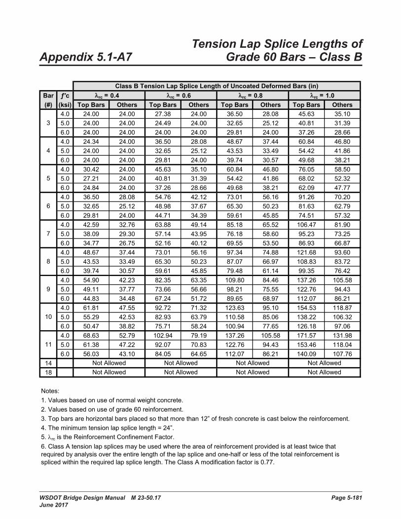
WSDOT Bridge Design Manual M 23-50.17 Page 5-181 June 2017
Tension Lap Splice Lengths of Appendix 5.1-A7 Grade 60 Bars – Class BTension Lap Splice Lengths ofAppendix 5.1-A7 Grade 60 Bars – Class B
Bar ƒ′c λrc = 0.4 λrc = 0.6 λrc = 0.8 λrc = 1.0(#) (ksi) Top Bars Others Top Bars Others Top Bars Others Top Bars Others
4 .0 24 .00 24 .00 27 .38 24 .00 36 .50 28 .08 45 .63 35 .105 .0 24 .00 24 .00 24 .49 24 .00 32 .65 25 .12 40 .81 31 .396 .0 24 .00 24 .00 24 .00 24 .00 29 .81 24 .00 37 .26 28 .664 .0 24 .34 24 .00 36 .50 28 .08 48 .67 37 .44 60 .84 46 .805 .0 24 .00 24 .00 32 .65 25 .12 43 .53 33 .49 54 .42 41 .866 .0 24 .00 24 .00 29 .81 24 .00 39 .74 30 .57 49 .68 38 .214 .0 30 .42 24 .00 45 .63 35 .10 60 .84 46 .80 76 .05 58 .505 .0 27 .21 24 .00 40 .81 31 .39 54 .42 41 .86 68 .02 52 .326 .0 24 .84 24 .00 37 .26 28 .66 49 .68 38 .21 62 .09 47 .774 .0 36 .50 28 .08 54 .76 42 .12 73 .01 56 .16 91 .26 70 .205 .0 32 .65 25 .12 48 .98 37 .67 65 .30 50 .23 81 .63 62 .796 .0 29 .81 24 .00 44 .71 34 .39 59 .61 45 .85 74 .51 57 .324 .0 42 .59 32 .76 63 .88 49 .14 85 .18 65 .52 106 .47 81 .905 .0 38 .09 29 .30 57 .14 43 .95 76 .18 58 .60 95 .23 73 .256 .0 34 .77 26 .75 52 .16 40 .12 69 .55 53 .50 86 .93 66 .874 .0 48 .67 37 .44 73 .01 56 .16 97 .34 74 .88 121 .68 93 .605 .0 43 .53 33 .49 65 .30 50 .23 87 .07 66 .97 108 .83 83 .726 .0 39 .74 30 .57 59 .61 45 .85 79 .48 61 .14 99 .35 76 .424 .0 54 .90 42 .23 82 .35 63 .35 109 .80 84 .46 137 .26 105 .585 .0 49 .11 37 .77 73 .66 56 .66 98 .21 75 .55 122 .76 94 .436 .0 44 .83 34 .48 67 .24 51 .72 89 .65 68 .97 112 .07 86 .214 .0 61 .81 47 .55 92 .72 71 .32 123 .63 95 .10 154 .53 118 .875 .0 55 .29 42 .53 82 .93 63 .79 110 .58 85 .06 138 .22 106 .326 .0 50 .47 38 .82 75 .71 58 .24 100 .94 77 .65 126 .18 97 .064 .0 68 .63 52 .79 102 .94 79 .19 137 .26 105 .58 171 .57 131 .985 .0 61 .38 47 .22 92 .07 70 .83 122 .76 94 .43 153 .46 118 .046 .0 56 .03 43 .10 84 .05 64 .65 112 .07 86 .21 140 .09 107 .76
1418
Notes:1. Values based on use of normal weight concrete.2. Values based on use of grade 60 reinforcement.3. Top bars are horizontal bars placed so that more than 12” of fresh concrete is cast below the reinforcement.4. The minimum tension lap splice length = 24”.5 . λrc is the Reinforcement Confinement Factor .
8
9
10
11
3
4
5
6
7
Class B Tension Lap Splice Length of Uncoated Deformed Bars (in)
Not Allowed Not Allowed Not Allowed Not AllowedNot Allowed Not Allowed Not Allowed Not Allowed
6. Class A tension lap splices may be used where the area of reinforcement provided is at least twice that required by analysis over the entire length of the lap splice and one-half or less of the total reinforcement is spliced within the required lap splice length. The Class A modification factor is 0.77.

Concrete Structures Chapter 5
Page 5-182 WSDOT Bridge Design Manual M 23-50.17 June 2017
Bar ƒ′c λrc = 0.4 λrc = 0.6 λrc = 0.8 λrc = 1.0(#) (ksi) Top Bars Others Top Bars Others Top Bars Others Top Bars Others
4 .0 24 .00 24 .00 35 .80 31 .59 47 .74 42 .12 59 .67 52 .655 .0 24 .00 24 .00 32 .02 28 .25 42 .70 37 .67 53 .37 47 .096 .0 24 .00 24 .00 29 .23 25 .79 38 .98 34 .39 48 .72 42 .994 .0 31 .82 28 .08 47 .74 42 .12 63 .65 56 .16 79 .56 70 .205 .0 28 .46 25 .12 42 .70 37 .67 56 .93 50 .23 71 .16 62 .796 .0 25 .98 24 .00 38 .98 34 .39 51 .97 45 .85 64 .96 57 .324 .0 39 .78 35 .10 59 .67 52 .65 79 .56 70 .20 99 .45 87 .755 .0 35 .58 31 .39 53 .37 47 .09 71 .16 62 .79 88 .95 78 .496 .0 32 .48 28 .66 48 .72 42 .99 64 .96 57 .32 81 .20 71 .654 .0 47 .74 42 .12 71 .60 63 .18 95 .47 84 .24 119 .34 105 .305 .0 42 .70 37 .67 64 .04 56 .51 85 .39 75 .35 106 .74 94 .186 .0 38 .98 34 .39 58 .46 51 .59 77 .95 68 .78 97 .44 85 .984 .0 55 .69 49 .14 83 .54 73 .71 111 .38 98 .28 139 .23 122 .855 .0 49 .81 43 .95 74 .72 65 .93 99 .62 87 .90 124 .53 109 .886 .0 45 .47 40 .12 68 .21 60 .18 90 .94 80 .25 113 .68 100 .314 .0 63 .65 56 .16 95 .47 84 .24 127 .30 112 .32 159 .12 140 .405 .0 56 .93 50 .23 85 .39 75 .35 113 .86 100 .46 142 .32 125 .586 .0 51 .97 45 .85 77 .95 68 .78 103 .94 91 .71 129 .92 114 .644 .0 71 .79 63 .35 107 .69 95 .02 143 .59 126 .70 179 .49 158 .375 .0 64 .22 56 .66 96 .32 84 .99 128 .43 113 .32 160 .54 141 .656 .0 58 .62 51 .72 87 .93 77 .59 117 .24 103 .45 146 .55 129 .314 .0 80 .83 71 .32 121 .25 106 .98 161 .67 142 .65 202 .08 178 .315 .0 72 .30 63 .79 108 .45 95 .69 144 .60 127 .59 180 .75 159 .486 .0 66 .00 58 .24 99 .00 87 .35 132 .00 116 .47 165 .00 145 .594 .0 89 .74 79 .19 134 .62 118 .78 179 .49 158 .37 224 .36 197 .965 .0 80 .27 70 .83 120 .40 106 .24 160 .54 141 .65 200 .67 177 .066 .0 73 .28 64 .65 109 .91 96 .98 146 .55 129 .31 183 .19 161 .64
1418
Notes:1. Values based on use of normal weight concrete.2. Values based on use of grade 60 reinforcement.3. Top bars are horizontal bars placed so that more than 12” of fresh concrete is cast below the reinforcement.4. The minimum tension lap splice length = 24”.5 . λrc is the Reinforcement Confinement Factor .
Class B Tension Lap Splice Length of Epoxy Coated Deformed Bars (in)(cover less than 3db or clear spacing between bars less than 6db)
λcf = 1.5
3
4
5
6
7
8
9
10
11
6. Class A tension lap splices may be used where the area of reinforcement provided is at least twice that required by analysis over the entire length of the lap splice and one-half or less of the total reinforcement is spliced within the required lap splice length. The Class A modification factor is 0.77.
Not AllowedNot Allowed
Not AllowedNot Allowed
Not AllowedNot Allowed
Not AllowedNot Allowed
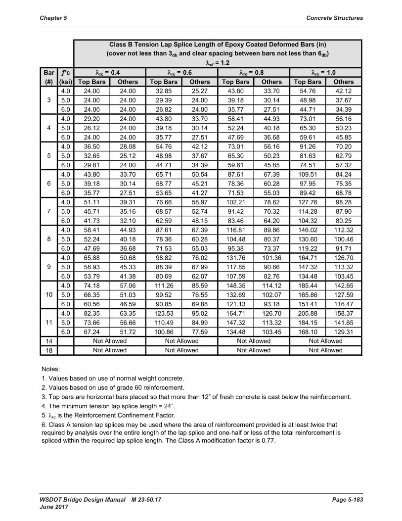
Chapter 5 Concrete Structures
WSDOT Bridge Design Manual M 23-50.17 Page 5-183 June 2017
Bar ƒ′c λrc = 0.4 λrc = 0.6 λrc = 0.8 λrc = 1.0(#) (ksi) Top Bars Others Top Bars Others Top Bars Others Top Bars Others
4 .0 24 .00 24 .00 32 .85 25 .27 43 .80 33 .70 54 .76 42 .125 .0 24 .00 24 .00 29 .39 24 .00 39 .18 30 .14 48 .98 37 .676 .0 24 .00 24 .00 26 .82 24 .00 35 .77 27 .51 44 .71 34 .394 .0 29 .20 24 .00 43 .80 33 .70 58 .41 44 .93 73 .01 56 .165 .0 26 .12 24 .00 39 .18 30 .14 52 .24 40 .18 65 .30 50 .236 .0 24 .00 24 .00 35 .77 27 .51 47 .69 36 .68 59 .61 45 .854 .0 36 .50 28 .08 54 .76 42 .12 73 .01 56 .16 91 .26 70 .205 .0 32 .65 25 .12 48 .98 37 .67 65 .30 50 .23 81 .63 62 .796 .0 29 .81 24 .00 44 .71 34 .39 59 .61 45 .85 74 .51 57 .324 .0 43 .80 33 .70 65 .71 50 .54 87 .61 67 .39 109 .51 84 .245 .0 39 .18 30 .14 58 .77 45 .21 78 .36 60 .28 97 .95 75 .356 .0 35 .77 27 .51 53 .65 41 .27 71 .53 55 .03 89 .42 68 .784 .0 51 .11 39 .31 76 .66 58 .97 102 .21 78 .62 127 .76 98 .285 .0 45 .71 35 .16 68 .57 52 .74 91 .42 70 .32 114 .28 87 .906 .0 41 .73 32 .10 62 .59 48 .15 83 .46 64 .20 104 .32 80 .254 .0 58 .41 44 .93 87 .61 67 .39 116 .81 89 .86 146 .02 112 .325 .0 52 .24 40 .18 78 .36 60 .28 104 .48 80 .37 130 .60 100 .466 .0 47 .69 36 .68 71 .53 55 .03 95 .38 73 .37 119 .22 91 .714 .0 65 .88 50 .68 98 .82 76 .02 131 .76 101 .36 164 .71 126 .705 .0 58 .93 45 .33 88 .39 67 .99 117 .85 90 .66 147 .32 113 .326 .0 53 .79 41 .38 80 .69 62 .07 107 .59 82 .76 134 .48 103 .454 .0 74 .18 57 .06 111 .26 85 .59 148 .35 114 .12 185 .44 142 .655 .0 66 .35 51 .03 99 .52 76 .55 132 .69 102 .07 165 .86 127 .596 .0 60 .56 46 .59 90 .85 69 .88 121 .13 93 .18 151 .41 116 .474 .0 82 .35 63 .35 123 .53 95 .02 164 .71 126 .70 205 .88 158 .375 .0 73 .66 56 .66 110 .49 84 .99 147 .32 113 .32 184 .15 141 .656 .0 67 .24 51 .72 100 .86 77 .59 134 .48 103 .45 168 .10 129 .31
1418
Notes:1. Values based on use of normal weight concrete.2. Values based on use of grade 60 reinforcement.3. Top bars are horizontal bars placed so that more than 12” of fresh concrete is cast below the reinforcement.4. The minimum tension lap splice length = 24”.5 . λrc is the Reinforcement Confinement Factor .
3
11
4
5
6
7
8
9
10
Not Allowed Not Allowed Not Allowed Not Allowed
Class B Tension Lap Splice Length of Epoxy Coated Deformed Bars (in)(cover not less than 3db and clear spacing between bars not less than 6db)
λcf = 1.2
6. Class A tension lap splices may be used where the area of reinforcement provided is at least twice that required by analysis over the entire length of the lap splice and one-half or less of the total reinforcement is spliced within the required lap splice length. The Class A modification factor is 0.77.
Not Allowed Not Allowed Not Allowed Not Allowed

Page 5-184 WSDOT Bridge Design Manual M 23-50.17 June 2017
Prestressing Strand Properties Appendix 5.1-A8 and Development Length
AASHTO M203 Grade 270 Uncoated Prestressing Strands Properties and Development Length
Strand Diameter (in)
Weight (lbs/ft)
Nominal Diameter (in) Area (in2) Transfer
length (in)Develop. Length k
= 1.0 (ft)Develop. Length k
= 1.6 (ft)3/8 0 .290 0 .375 0 .085 22 .5 5 .05 8 .08
7/16 0 .390 0 .438 0 .115 26 .3 5 .90 9 .44
1/2 0 .520 0 .500 0 .153 30 .0 6 .74 10 .78
1/2 S 0 .568 0 .520 0 .167 31 .2 7 .01 11 .21
9/16 0 .651 0 .563 0 .192 33 .8 7 .58 12 .14
0 .60 0 .740 0 .600 0 .217 36 .0 8 .08 12 .93
0 .62 0 .788 0 .620 0 .231 37 .2 8 .35 13 .36
0 .70 1 .000 0 .700 0 .294 42 .0 9 .43 15 .09
Assumptions for determining development length: ƒps = ƒpu = 270 ksi ƒpe = (270 ksi x 0.75)–40 ksi = 162.5 ksi

WSDOT Bridge Design Manual M 23-50.17 Page 5-185 June 2017
Appendix 5.2-A1 Working Stress Design
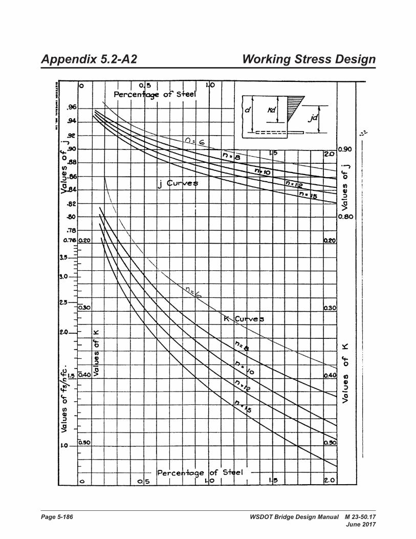
Page 5-186 WSDOT Bridge Design Manual M 23-50.17 June 2017
Appendix 5.2-A2 Working Stress Design
Bridge Design Manual M 23-50 Page 5.2-A2-1 June 2006
Appendix 5.2-A2
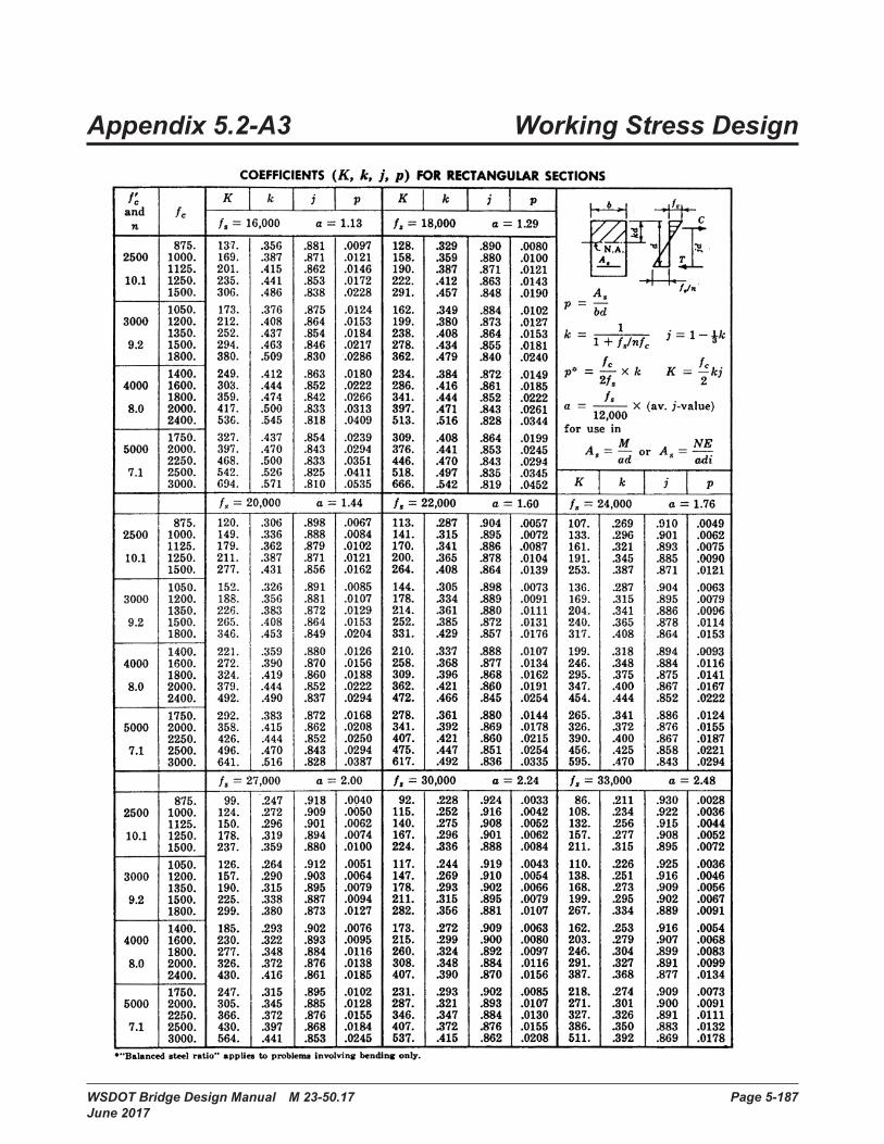
WSDOT Bridge Design Manual M 23-50.17 Page 5-187 June 2017
Appendix 5.2-A3 Working Stress Design
Bridge Design Manual M 23-50 Page 5.2-A3-1 June 2006
Appendix 5.2-A3
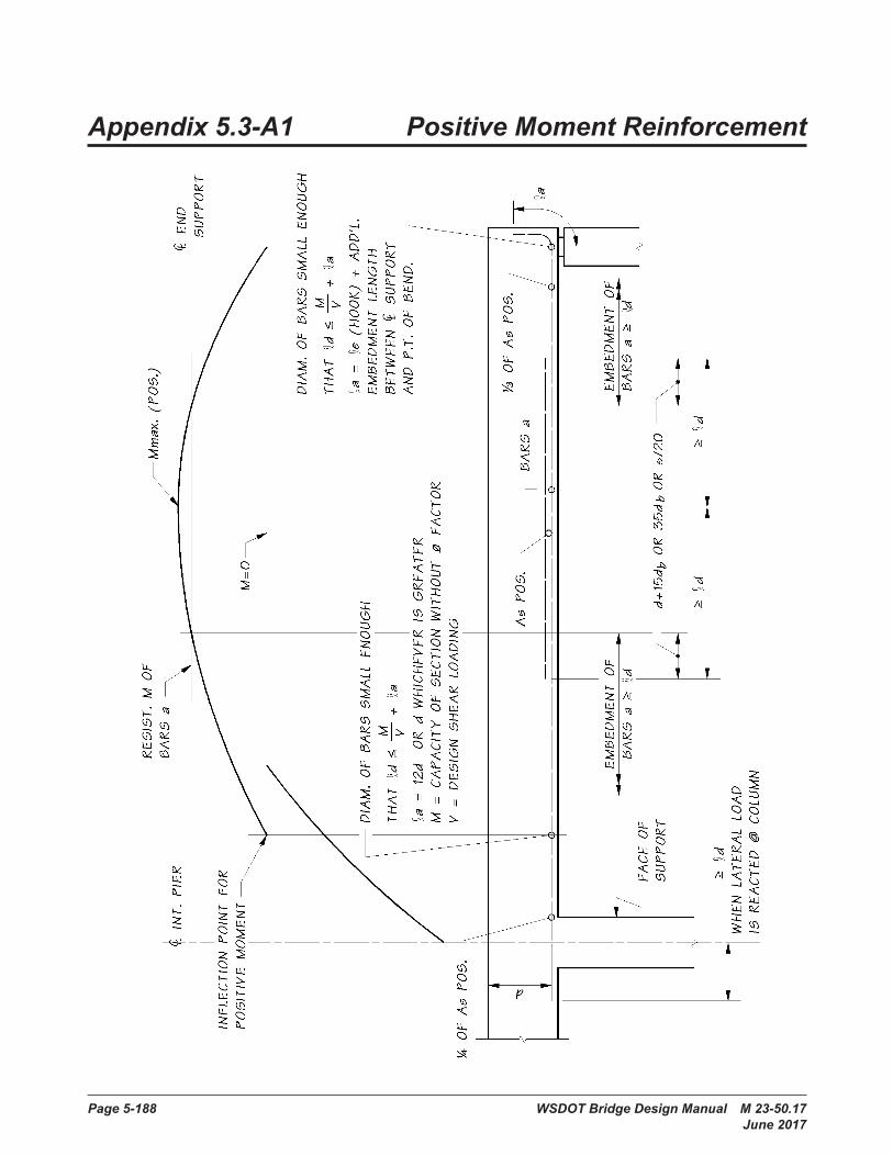
Page 5-188 WSDOT Bridge Design Manual M 23-50.17 June 2017
Appendix 5.3-A1 Positive Moment Reinforcement

WSDOT Bridge Design Manual M 23-50.17 Page 5-189 June 2017
Appendix 5.3-A2 Negative Moment Reinforcement
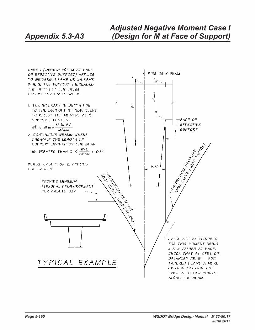
Page 5-190 WSDOT Bridge Design Manual M 23-50.17 June 2017
Adjusted Negative Moment Case I Appendix 5.3-A3 (Design for M at Face of Support)
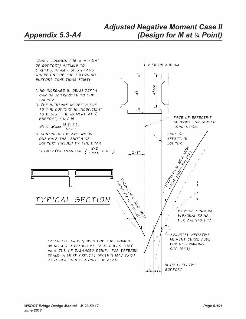
WSDOT Bridge Design Manual M 23-50.17 Page 5-191 June 2017
Adjusted Negative Moment Case II Appendix 5.3-A4 (Design for M at 1/4 Point)
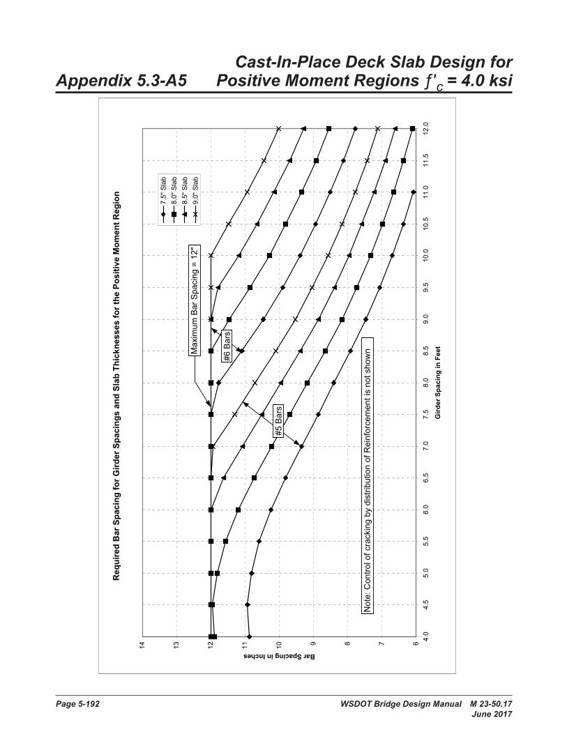
Page 5-192 WSDOT Bridge Design Manual M 23-50.17 June 2017
Cast-In-Place Deck Slab Design for Appendix 5.3-A5 Positive Moment Regions ƒ′c = 4.0 ksi
Sla
b D
esig
n C
harts
Req
uire
d B
ar S
paci
ng fo
r Gird
er S
paci
ngs
and
Slab
Thi
ckne
sses
for t
he P
ositi
ve M
omen
t Reg
ion
67891011121314
4.0
4.5
5.0
5.5
6.0
6.5
7.0
7.5
8.0
8.5
9.0
9.5
10.0
10.5
11.0
11.5
12.0
Gird
er S
paci
ng in
Fee
t
Bar Spacing in Inches
7.5"
Sla
b8.
0" S
lab
8.5"
Sla
b9.
0" S
lab
#6 B
ars
#5 B
ars
Max
imum
Bar
Spa
cing
= 1
2"
Not
e: C
ontro
l of c
rack
ing
by d
istri
butio
n of
Rei
nfor
cem
ent i
s no
t sho
wn
Pag
e 1
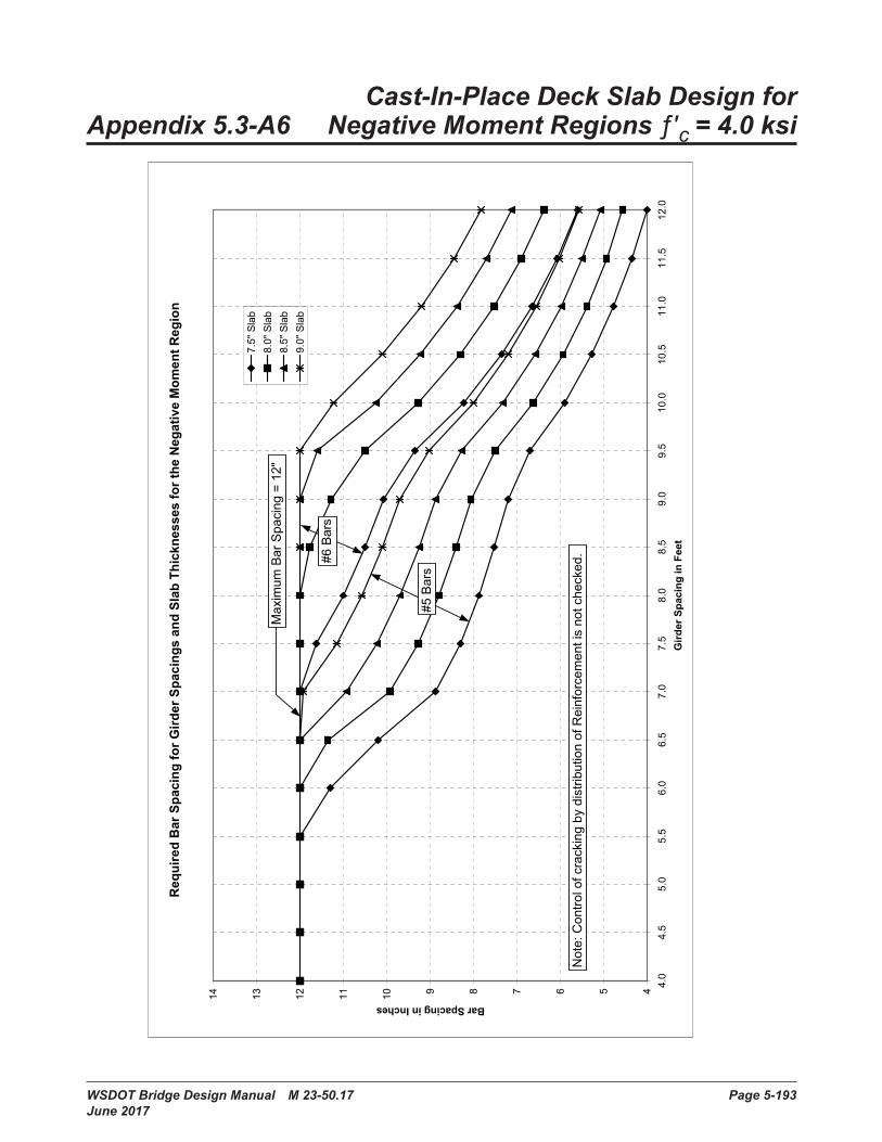
WSDOT Bridge Design Manual M 23-50.17 Page 5-193 June 2017
Cast-In-Place Deck Slab Design for Appendix 5.3-A6 Negative Moment Regions ƒ′c = 4.0 ksi
Sla
b D
esig
n C
harts
Req
uire
d B
ar S
paci
ng fo
r Gird
er S
paci
ngs
and
Slab
Thi
ckne
sses
for t
he N
egat
ive
Mom
ent R
egio
n
4567891011121314
4.0
4.5
5.0
5.5
6.0
6.5
7.0
7.5
8.0
8.5
9.0
9.5
10.0
10.5
11.0
11.5
12.0
Gird
er S
paci
ng in
Fee
t
Bar Spacing in Inches
7.5"
Sla
b8.
0" S
lab
8.5"
Sla
b9.
0" S
lab
Max
imum
Bar
Spa
cing
= 1
2"
#6 B
ars
#5 B
ars
Not
e: C
ontro
l of c
rack
ing
by d
istri
butio
n of
Rei
nfor
cem
ent i
s no
t che
cked
.
Pag
e 1

Page 5-194 WSDOT Bridge Design Manual M 23-50.17 June 2017
Slab Overhang Design- Appendix 5.3-A7 Interior Barrier Segment
Slab Overhang Required Reinforcement for Vehicle Impact -
Interior Barrier Segment - LRFD A13.4.1 Design Case 1
0.4
0.6
0.8
1
1.2
1.4
1.6
1.8
2
2.2
2.4
2.6
2.8
3.5 3.75 4 4.25 4.5 4.75 5 5.25 5.5 5.75 6 6.25 6.5
d (in)
To
p M
at
Ste
el
As (
in2/f
t)
32in F Shape &34in Single Slope
42in F Shape & 42in Single Slope
Notes: 1. Top and bottom mats each carry one-half the tension impact load.2 . Only Design Case 1 of LRFD A13 .4 .1 is considered . Designer must also check Design Cases 2 and 3 .3. Section considered is a vertical section through the slab overhang at the toe of the barrier.
Slab Overhang Required Reinforcement for Vehicle Impact–Interior Barrier Segment–LRFD A13.4.1 Design Case 1
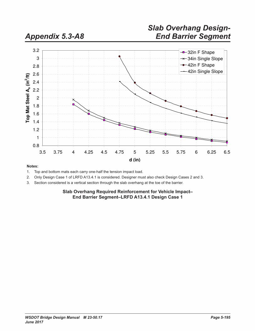
WSDOT Bridge Design Manual M 23-50.17 Page 5-195 June 2017
Slab Overhang Design- Appendix 5.3-A8 End Barrier Segment
Slab Overhang Required Reinforcement for Vehicle Impact -
End Barrier Segment - LRFD A13.4.1 Design Case 1
0.8
1
1.2
1.4
1.6
1.8
2
2.2
2.4
2.6
2.8
3
3.2
3.5 3.75 4 4.25 4.5 4.75 5 5.25 5.5 5.75 6 6.25 6.5
d (in)
To
p M
at
Ste
el
As (
in2/f
t)
32in F Shape
34in Single Slope
42in F Shape
42in Single Slope
Notes: 1. Top and bottom mats each carry one-half the tension impact load.2 . Only Design Case 1 of LRFD A13 .4 .1 is considered . Designer must also check Design Cases 2 and 3 .3. Section considered is a vertical section through the slab overhang at the toe of the barrier.
Slab Overhang Required Reinforcement for Vehicle Impact– End Barrier Segment–LRFD A13.4.1 Design Case 1

Page 5-196 WSDOT Bridge Design Manual M 23-50.17 June 2017
Appendix 5.6-A1-1 Span Capability of W GirdersSpan Capability of W Girders
Girder Type
Girder Spacing (ft)
CL Bearing to CL Bearing (ft)
"A" Dim . (in)
Deck Thickness (in)
Shipping Weight (kips)
5 85 10 .25 7 .50 366 80 10 .25 7 .50 347 75 10 .00 7 .50 328 70 10 .00 7 .50 309 65 9 .75 7 .50 2810 60 9 .75 7 .75 2611 55 10 .00 8 .25 2412 50 10 .00 8 .50 225 115 11 .00 7 .50 696 110 11 .00 7 .50 667 105 10 .75 7 .50 638 100 10 .75 7 .50 609 95 10 .50 7 .50 5710 90 10 .50 7 .75 5411 85 10 .75 8 .00 5112 80 11 .00 8 .50 485 130 11 .25 7 .50 896 125 11 .25 7 .50 867 120 11 .00 7 .50 828 115 11 .00 7 .50 799 110 11 .00 7 .50 7610 105 10 .75 7 .50 7211 100 11 .25 8 .00 6912 95 11 .50 8 .50 665 150 11 .00 7 .50 1276 145 11 .00 7 .50 1237 140 11 .25 7 .50 1198 135 11 .00 7 .50 1149 130 11 .00 7 .50 11010 125 11 .00 7 .50 10611 120 11 .25 7 .75 10212 115 11 .25 8 .00 98
Design Parameters:- PGSuper Version 2 .2 .3 .0- Girder f'ci = 7 .5 ksi, f'c = 9 .0 ksi- Slab f'c = 4.0 ksi.- No vertical or horizontal curve- 2% roadway crown slope- Standard WSDOT "F" shape barrier- 6% roadway superelevation for shipping check- Standard WSDOT Abutment End Type A- Includes 2" future HMA overlay with density of 140 pcf
W58G
W74G
W42G
W50G
Design Parameters:• PGSuper version 2 .2 .3 .0• Girder ƒ′ci = 7.5 ksi, ƒ′c = 9 .0 ksi• Slab ƒ′c = 4 .0 ksi• No horizontal or vertical curve• 2 percent roadway crown slope• Standard WSDOT "F" shape barrier• 6 percent roadway superelevation for shipping check• Standard WSDOT Abutment End Type A• Includes 2″ future HMA overlay with density of 140 pcf

WSDOT Bridge Design Manual M 23-50.17 Page 5.6-A1-2-5-197 June 2017
Appendix 5.6-A1-2 Span Capability of WF Girders Span Capability of WF Girders
Girder Type
Girder Spacing (ft)
CL Bearing to CL Bearing (ft) "A" Dim . (in)
Deck Thickness (in)
Shipping Weight (kips)
5 105 11 .25 7 .50 836 100 11 .25 7 .50 797 95 11 .25 7 .50 768 95 11 .25 7 .50 769 90 11 .25 7 .50 7210 85 11 .25 7 .50 6811 85 11 .00 7 .50 6812 80 11 .00 8 .00 645 120 11 .25 7 .50 1006 115 11 .25 7 .50 967 110 11 .50 7 .50 928 105 11 .25 7 .50 889 100 11 .25 7 .50 8410 95 11 .25 7 .50 8011 90 11 .25 7 .50 7512 90 11 .50 8 .00 755 140 11 .00 7 .50 1246 135 11 .25 7 .50 1197 125 11 .25 7 .50 1118 120 11 .50 7 .50 1079 115 11 .25 7 .50 10210 110 11 .25 7 .50 9811 110 11 .25 7 .50 9812 105 11 .50 8 .00 945 155 10 .75 7 .50 1456 150 11 .00 7 .50 1417 145 11 .25 7 .50 1368 140 11 .25 7 .50 1329 135 11 .25 7 .50 12710 130 11 .25 7 .50 12211 120 11 .25 7 .50 11312 120 11 .50 8 .00 1135 165 10 .75 7 .50 1646 160 10 .75 7 .50 1597 155 11 .00 7 .50 1548 150 11 .25 7 .50 1499 145 11 .25 7 .50 14410 140 11 .50 7 .50 13911 135 11 .25 7 .50 13512 130 11 .75 8 .00 1305 175 10 .50 7 .50 1836 170 10 .75 7 .50 1787 165 11 .00 7 .50 1738 160 11 .00 7 .50 1689 155 11 .25 7 .50 16310 150 11 .25 7 .50 15711 145 11 .25 7 .50 152
WF36G
WF42G
WF50G
WF58G
WF66G
WF74G

Concrete Structures Chapter 5
Page 5.6-A1-2-5-198 WSDOT Bridge Design Manual M 23-50.17 June 2017
12 140 11 .75 8 .00 1475 190 10 .00 7 .50 2106 185 10 .50 7 .50 2047 180 10 .50 7 .50 1998 170 10 .75 7 .50 1889 165 11 .00 7 .50 18310 160 11 .00 7 .50 17711 155 11 .00 7 .50 17212 150 11 .50 8 .00 1665 190 9 .50 7 .50 2266 185 9 .75 7 .50 2207 175 10 .25 7 .50 2088 175 10 .50 7 .50 2089 170 10 .75 7 .50 20210 165 10 .75 7 .50 19611 160 11 .00 7 .50 19112 155 11 .25 8 .00 1855 205 9 .50 7 .50 2516 200 10 .00 7 .50 2457 195 10 .00 7 .50 2398 185 10 .25 7 .50 2279 180 10 .50 7 .50 22110 175 10 .50 7 .50 21511 170 10 .50 7 .50 20912 165 11 .25 8 .00 203
Design Parameters:- PGSuper Version 2 .2 .3 .0- Girder f'ci = 7 .5 ksi, f'c = 9 .0 ksi- Slab f'c = 4.0 ksi.- No vertical or horizontal curve- 2% roadway crown slope- Standard WSDOT "F" shape barrier- 6% roadway superelevation for shipping check- Standard WSDOT Abutment End Type A- Includes 2" future HMA overlay with density of 140 pcf
WF83G
WF95G
WF100G
WF74G
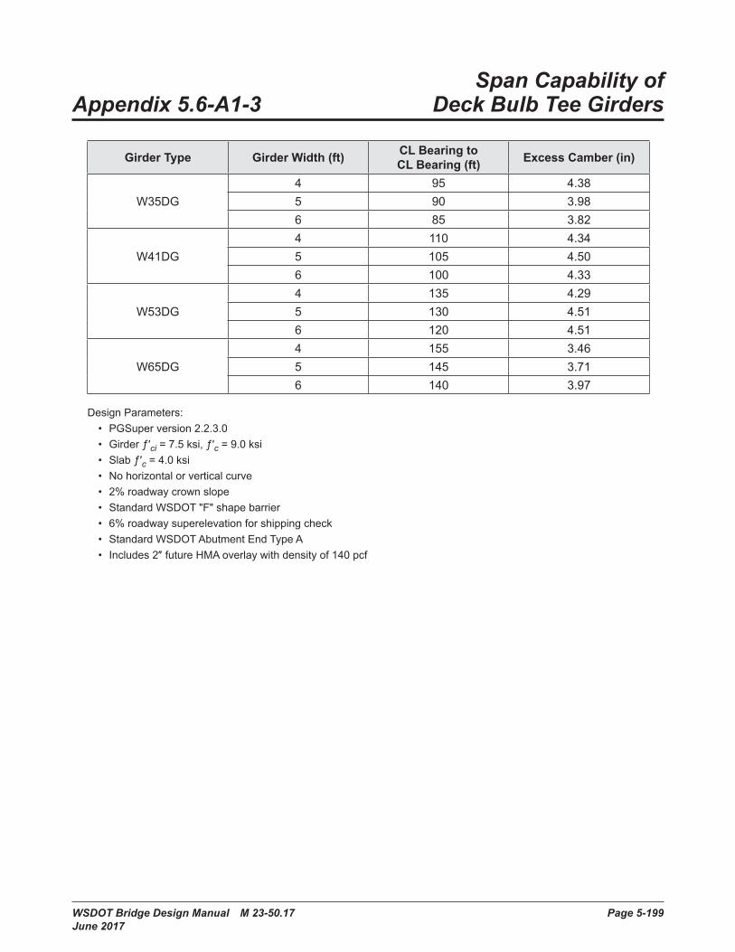
WSDOT Bridge Design Manual M 23-50.17 Page 5-199 June 2017
Span Capability of Appendix 5.6-A1-3 Deck Bulb Tee Girders
WSDOT Bridge Design Manual M 23-50.06 Page 5.6-A1-4-1 July 2011
Span Capability of Appendix 5.6-A1-4 Deck Bulb Tee Girders
Girder Type Girder Width (ft) CL Bearing to CL Bearing (ft) Excess Camber (in)
W35DG4 95 4 .385 90 3 .986 85 3 .82
W41DG4 110 4 .345 105 4 .506 100 4 .33
W53DG4 135 4 .295 130 4 .516 120 4 .51
W65DG4 155 3 .465 145 3 .716 140 3 .97
Design Parameters:• PGSuper version 2.2.3.0• Girder ƒ′ci = 7.5 ksi, ƒ′c = 9 .0 ksi• Slab ƒ′c = 4 .0 ksi• No horizontal or vertical curve• 2% roadway crown slope• Standard WSDOT "F" shape barrier• 6% roadway superelevation for shipping check• Standard WSDOT Abutment End Type A• Includes 2″ future HMA overlay with density of 140 pcf
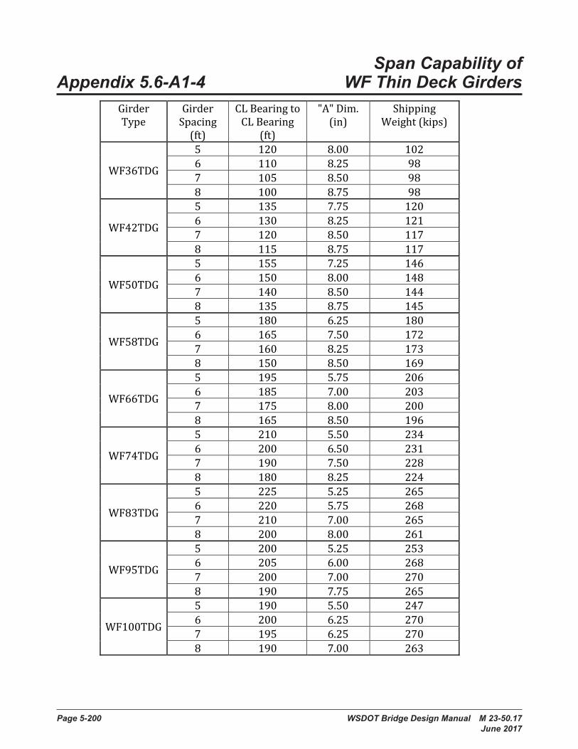
Page 5-200 WSDOT Bridge Design Manual M 23-50.17 June 2017
Span Capability of Appendix 5.6-A1-4 WF Thin Deck GirdersAppendix 5.6-A1-4: Span Capability of WF Thin Deck Girders
Girder Type
Girder Spacing
(ft)
CL Bearing to CL Bearing
(ft)
"A" Dim. (in)
Shipping Weight (kips)
WF36TDG
5 120 8.00 102 6 110 8.25 98 7 105 8.50 98 8 100 8.75 98
WF42TDG
5 135 7.75 120 6 130 8.25 121 7 120 8.50 117 8 115 8.75 117
WF50TDG
5 155 7.25 146 6 150 8.00 148 7 140 8.50 144 8 135 8.75 145
WF58TDG
5 180 6.25 180 6 165 7.50 172 7 160 8.25 173 8 150 8.50 169
WF66TDG
5 195 5.75 206 6 185 7.00 203 7 175 8.00 200 8 165 8.50 196
WF74TDG
5 210 5.50 234 6 200 6.50 231 7 190 7.50 228 8 180 8.25 224
WF83TDG
5 225 5.25 265 6 220 5.75 268 7 210 7.00 265 8 200 8.00 261
WF95TDG
5 200 5.25 253 6 205 6.00 268 7 200 7.00 270 8 190 7.75 265
WF100TDG
5 190 5.50 247 6 200 6.25 270 7 195 6.25 270 8 190 7.00 263

Chapter 5 Concrete Structures
WSDOT Bridge Design Manual M 23-50.17 Page 5-201 June 2017
Design Parameters:
- PGSuper Version 2.8.0 - Girder f'ci = 7.5 ksi, f'c = 9.0 ksi - 1/2 D40 ≥ C - Shipping weight < 270 kip - Slab f'c = 4.0 ksi. - No vertical or horizontal curve - 2% roadway crown slope - Standard WSDOT "F" shape barrier - 6% roadway superelevation for shipping check - Standard WSDOT Abutment End Type A - Includes 2" future HMA overlay with density of 140 pcf

Page 5-202 WSDOT Bridge Design Manual M 23-50.17 June 2017
Span Capability of Appendix 5.6-A1-5 WF Deck Girders
Appendix 5.6-A1-5: Span Capability of WF Deck Girders
Girder Type
Girder Spacing
(ft)
CL Bearing to CL
Bearing (ft)
Shipping Weight (kips)
WF39DG
5 115 122 6 110 126 7 100 123 8 100 131
WF45DG
5 130 143 6 125 148 7 115 146 8 105 142
WF53DG
5 145 167 6 140 173 7 130 172 8 125 176
WF61DG
5 160 193 6 155 200 7 145 200 8 135 198
WF69DG
5 170 215 6 165 223 7 155 222 8 150 228
WF77DG
5 185 244 6 180 253 7 175 261 8 165 260
WF86DG
5 195 270 6 180 264 7 170 264 8 160 262
WF98DG
5 180 265 6 170 265 7 160 263 8 155 268
WF103DG
5 175 264 6 165 263 7 160 269 8 150 264

Chapter 5 Concrete Structures
WSDOT Bridge Design Manual M 23-50.17 Page 5-203 June 2017
Design Parameters:
- PGSuper Version 2.8.0 - Girder f'ci = 7.5 ksi, f'c = 9.0 ksi - 1/2 D40 ≥ C - Shipping weight < 270 kip - No vertical or horizontal curve - 2% roadway crown slope - Standard WSDOT "F" shape barrier - 6% roadway superelevation for shipping check - Standard WSDOT Abutment End Type A - 1½” concrete overlay

Page 5-204 WSDOT Bridge Design Manual M 23-50.17 June 2017
Span Capability of Trapezoidal Appendix 5.6-A1-6 Tub Girders without Top Flange
Span Capability of Trapezoidal Tub Girders without Top Flange
Girder Type
Girder Spacing (ft)
CL Bearing to CL Bearing (ft) "A" Dim . (in)
Deck Thickness (in)
Shipping Weight (kips)
8 130 8 .25 7 .50 15310 125 8 .25 7 .50 14712 120 8 .50 7 .50 14214 115 8 .50 7 .50 1369 130 8 .25 7 .50 16411 125 8 .50 7 .50 15813 120 8 .75 7 .50 15115 115 8 .50 7 .50 1458 150 8 .25 7 .50 20510 145 8 .25 7 .50 19812 140 8 .25 7 .50 19214 130 8 .50 7 .50 1789 150 8 .25 7 .50 21711 145 8 .25 7 .50 21013 140 8 .25 7 .50 20315 135 8 .50 7 .50 1968 170 # 8 .25 7 .50 26410 160 8 .25 7 .50 24912 155 8 .25 7 .50 24214 145 8 .50 7 .50 22616 135 9 .00 8 .00 2119 170 # 8 .25 7 .50 27811 165 # 8 .25 7 .50 27013 160 # 8 .25 7 .50 26215 155 # 8 .25 7 .50 25417 150 8 .75 8 .00 246
# Span capability exceeds maximum shipping weight of 252 kips
Design Parameters:- PGSuper Version 2 .2 .3 .0- Girder f'ci = 7 .5 ksi, f'c = 9 .0 ksi- Slab f'c = 4.0 ksi.- No vertical or horizontal curve- 2% roadway crown slope- Standard WSDOT "F" shape barrier- 6% roadway superelevation for shipping check- Standard WSDOT Abutment End Type A- Includes 2" future HMA overlay with density of 140 pcf
U54G4
U54G5
U66G4
U66G5
U78G4
U78G5
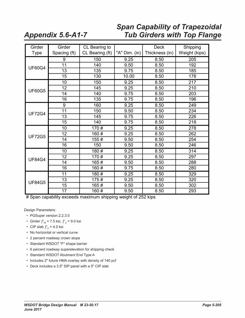
WSDOT Bridge Design Manual M 23-50.17 Page 5-205 June 2017
Span Capability of Trapezoidal Appendix 5.6-A1-7 Tub Girders with Top Flange
Design Parameters:• PGSuper version 2 .2 .3 .0• Girder ƒ′ci = 7.5 ksi, ƒ′c = 9 .0 ksi• CIP slab ƒ′c = 4 .0 ksi• No horizontal or vertical curve• 2 percent roadway crown slope• Standard WSDOT "F" shape barrier• 6 percent roadway superelevation for shipping check• Standard WSDOT Abutment End Type A• Includes 2″ future HMA overlay with density of 140 pcf• Deck includes a 3.5″ SIP panel with a 5″ CIP slab
Span Capability of Trapezoidal Tub Girders with Top Flange
Girder Type
Girder Spacing (ft)
CL Bearing to CL Bearing (ft) "A" Dim . (in)
Deck Thickness (in)
Shipping Weight (kips)
9 150 9 .25 8 .50 20511 140 9 .50 8 .50 19213 135 9 .75 8 .50 18515 130 10 .00 8 .50 17810 150 9 .25 8 .50 21712 145 9 .25 8 .50 21014 140 9 .75 8 .50 20316 135 9 .75 8 .50 1969 160 9 .25 8 .50 24911 150 9 .50 8 .50 23413 145 9 .75 8 .50 22615 140 9 .75 8 .50 21810 170 # 9 .25 8 .50 27812 160 # 9 .25 8 .50 26214 155 # 9 .50 8 .50 25416 150 9 .50 8 .50 24610 180 # 9 .25 8 .50 31412 170 # 9 .25 8 .50 29714 165 # 9 .50 8 .50 28816 160 # 9 .75 8 .50 28011 180 # 9 .25 8 .50 32913 175 # 9 .25 8 .50 32015 165 # 9 .50 8 .50 30217 160 # 9 .50 8 .50 293
# Span capability exceeds maximum shipping weight of 252 kips
Design Parameters:- PGSuper Version 2 .2 .3 .0- Girder f'ci = 7 .5 ksi, f'c = 9 .0 ksi- CIP Slab f'c = 4.0 ksi.- No vertical or horizontal curve- 2% roadway crown slope- Standard WSDOT "F" shape barrier- 6% roadway superelevation for shipping check- Standard WSDOT Abutment End Type A- Includes 2" future HMA overlay with density of 140 pcf- Deck includes a 3.5" Stay-In-Place Panel with a 5" CIP Slab
UF60G4
UF60G5
UF72G4
UF72G5
UF84G4
UF84G5
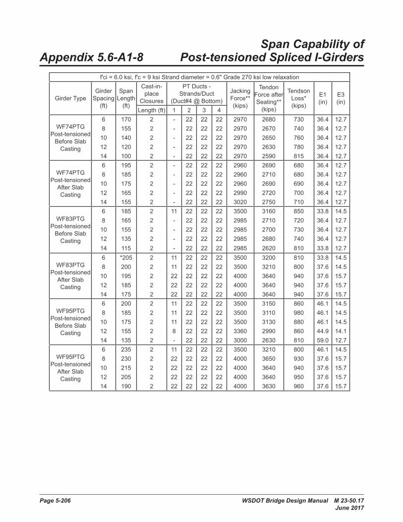
Page 5-206 WSDOT Bridge Design Manual M 23-50.17 June 2017
Span Capability of Appendix 5.6-A1-8 Post-tensioned Spliced I-Girders
Bridge Design Manual M 23-50.02 Page 5.6-A1-12-1 May 2008
Chapter 5 Concrete Structures
Span Capability of Appendix 5.6-A1-12 Post-Tensioned Spliced I-Girders
f'ci = 6.0 ksi, f'c = 9 ksi Strand diameter = 0.6" Grade 270 ksi low relaxation
Girder TypeGirder
Spacing (ft)
Span Length
(ft)
Cast-in-place
Closures
PT Ducts - Strands/Duct
(Duct#4 @ Bottom)
Jacking Force** (kips)
Tendon Force after Seating**
(kips)
Tendson Loss* (kips)
E1 (in)
E3 (in)
Length (ft) 1 2 3 4
WF74PTG Post-tensioned
Before Slab Casting
6 170 2 - 22 22 22 2970 2680 730 36.4 12.78 155 2 - 22 22 22 2970 2670 740 36.4 12.710 140 2 - 22 22 22 2970 2650 760 36.4 12.712 120 2 - 22 22 22 2970 2630 780 36.4 12.714 100 2 - 22 22 22 2970 2590 815 36.4 12.7
WF74PTG Post-tensioned
After Slab Casting
6 195 2 - 22 22 22 2960 2690 680 36.4 12.78 185 2 - 22 22 22 2960 2710 680 36.4 12.710 175 2 - 22 22 22 2960 2690 690 36.4 12.712 165 2 - 22 22 22 2990 2720 700 36.4 12.714 155 2 - 22 22 22 3020 2750 710 36.4 12.7
WF83PTG Post-tensioned
Before Slab Casting
6 185 2 11 22 22 22 3500 3160 850 33.8 14.58 165 2 - 22 22 22 2985 2710 720 36.4 12.710 155 2 - 22 22 22 2985 2700 730 36.4 12.712 135 2 - 22 22 22 2985 2680 740 36.4 12.714 115 2 - 22 22 22 2985 2620 810 33.8 12.7
WF83PTG Post-tensioned
After Slab Casting
6 *205 2 11 22 22 22 3500 3200 810 33.8 14.58 200 2 11 22 22 22 3500 3210 800 37.6 14.510 195 2 22 22 22 22 4000 3640 940 37.6 15.712 185 2 22 22 22 22 4000 3640 940 37.6 15.714 175 2 22 22 22 22 4000 3640 940 37.6 15.7
WF95PTG Post-tensioned
Before Slab Casting
6 200 2 11 22 22 22 3500 3150 860 46.1 14.58 185 2 11 22 22 22 3500 3110 980 46.1 14.510 175 2 11 22 22 22 3500 3130 880 46.1 14.512 155 2 8 22 22 22 3360 2990 860 44.9 14.114 135 2 - 22 22 22 3000 2630 810 59.0 12.7
WF95PTG Post-tensioned
After Slab Casting
6 235 2 11 22 22 22 3500 3210 800 46.1 14.58 230 2 22 22 22 22 4000 3650 930 37.6 15.710 215 2 22 22 22 22 4000 3640 940 37.6 15.712 205 2 22 22 22 22 4000 3640 950 37.6 15.714 190 2 22 22 22 22 4000 3630 960 37.6 15.7

Chapter 5 Concrete Structures
WSDOT Bridge Design Manual M 23-50.17 Page 5-207 June 2017
* Controlled by over-reinforced section (see LRFD Sec. 5.7.3.3)** Total force calculated at jacking end of post-tensioned girder (rounded to the nearest 10)
Design Parameters:• PGSplice V . 0 .3• WSDOT BDM LRFD design criteria• No vertical or horizontal curve• 2 .0 percent roadway crown slope• Interior girder with barrier load (6 girder bridge)• Only flexural service and strength checked; lifting and hauling checks not necessarily satisfed• Simple girder span lengths are CL bearing to CL bearing• Slab ƒ′c = 4 .0 ksi• Standard WSDOT “F” shape barrier• Under normal exposure condition and 75 percent relative humidity• Spans reported in 5′-0″ increments• Designs based on “normally” reinforced sections (c/de < 0.42 LRFD 5.7.3.3)• Designs based on 22 strands/duct• For 6′-10′ girder spacing -- 7.5″ slab• For 12′ girder spacing -- 8.0″ slab• For 14′ girder spacing -- 8.75″ slab• Girders post-tensioned before slab pour are assumed to be post-tensioned adjacent to structure.• All spec checks at wet joints have been ignored. It isassumed that the designer can modify the wet joints to reach the
required span as shown in the table. These modifcations are outside the scope of this table.

Page 5-208 WSDOT Bridge Design Manual M 23-50.17 June 2017
Span Capability of Post-tensioned Appendix 5.6-A1-9 Spliced Tub Girders
Bridge Design Manual M 23-50.02 Page 5.6-A1-13-1 May 2008
Chapter 5 Concrete Structures
Span Capability of Post- Appendix 5.6-A1-13 Tensioned Spliced Tub Girders
Gird
er
Type
Gird
er
Spa
cing
(ft
)
Spa
n Le
ngth
(ft
)
End
Seg
men
tsM
iddl
e S
egm
ent
Spl
iced
Pos
t-ten
sion
ed G
irder
No.
of S
traig
ht
Stra
nds
No.
of S
traig
ht
Stra
nds
PT
Duc
ts ~
S
trand
s/D
uct
(Duc
t #4
@ B
otto
m)
Jack
ing
Forc
e*
(kip
s)
Tend
on F
orce
af
ter S
eatin
g*
(kip
s)
Tend
on
Loss
* (k
ips)
E1
(in)
E3
(in)
12
34
U54
PTG
48
135
46
--
1122
2904
2636
570
20.0
8.9
1415
04
14-
222
2240
4837
0876
031
.510
.1
U54
PTG
59
135
48
--
1222
2992
2764
578
19.7
9.0
1515
04
14-
622
2244
0040
3282
629
.810
.9
U54
PTG
610
135
46
--
1822
3520
3200
684
18.3
9.5
1614
54
14-
822
2245
7641
9685
229
.011
.2
U66
PTG
48
155
48
--
1522
3256
2944
648
18.9
9.3
1417
04
16-
722
2244
8840
8886
429
.411
.0
U66
PTG
59
155
48
--
1722
3432
3110
678
18.5
9.4
1517
04
16-
1022
2247
5243
3491
029
.311
.3
U66
PTG
610
155
48
--
2122
3784
3434
742
17.7
9.7
1616
54
14-
1222
2249
2845
0094
027
.711
.7
U78
PTG
48
175
410
--
1922
3608
3262
722
18.1
9.6
1619
04
20-
1522
2251
9247
1810
1426
.812
.1
U78
PTG
59
180
410
-2
2222
4048
3692
776
31.5
10.1
1719
54
22-
2122
2257
2052
0211
1025
.212
.6
U78
PTG
610
180
410
-6
2222
4400
4018
840
29.8
10.9
1819
0#4
202
2222
2258
9654
0011
0439
5.0
12.9
Chapter 5 Concrete Structures
WSDOT Bridge Design Manual M 23-50.17 Page 5-209 June 2017
Total force calculated at jacking end of post-tensioned girder# Span capability exceeds maximum shipping weight of 200 kips
Design Parameters:• PGSplice V . 0 .3• WSDOT BDM LRFD design criteria• No vertical or horizontal curve• 2 .0 percent roadway crown slope• Interior girder with barrier load (6 girder bridge)• Only flexural service and strength checked; lifting and hauling checks not necessarily satisfied• Simple girder span lengths are CL bearing to CL bearing• Standard WSDOT “F” shape barrier• Under normal exposure condition and 75 percent humidity• Spans reported in 5′-0″ increments• “A” dimension = deck thickness + 2″• Closure pour for spliced girders is 2′, ƒ′ci = 6.0 ksi, ƒ′c = 9 ksi• Girder ƒ′ci = 6.0 ksi, ƒ′c = 9.0 ksi, slab ƒ′c = 4 .0 ksi• Girders are spliced in-place after slab is cast• Prestressing and post-tensioning steel is 0.6″ diameter, Grade 270• End segments are 25 percent of total length; center segment is 50 percent of total length• Range of applicability requirements in LRFD ignored; span lengths may be longer than allowed by LRFD• Designs are based on a 22 diameter strand limit per 4″ duct for high pressure grout• All spec checks at wet joints have been ignored. It is assumed that the designer can modify the wet joints to reach the
required span as shown in the table. These modifications are outside the scope of this table.

Page 5-210 WSDOT Bridge Design Manual M 23-50.17 June 2017
“A” Dimension for Appendix 5-B1 Precast Girder Bridges
IntroductionTheslabhaunchisthedistancebetweenthetopofagirderandthebottomoftheroadwayslab.Thehaunchvariesindepthalongthelengthofthegirderaccommodatingthegirdercamberandgeometriceffectsoftheroadwaysurfaceincluding super elevations, vertical curves and horizontal curves.
Thebasicconceptindeterminingtherequired“A”dimensionistoprovideahaunchoverthegirdersuchthatthetopofthegirderisnotlessthanthefilletdepth(typically¾″)belowthebottomoftheslabatthecenterofthespan.Thisprovidesthattheactualgirdercambercouldexceedthecalculatedvalueby1¾″beforethetopofthegirderwouldinterferewiththebottommatofslabreinforcement.
Itisdesirabletohavepointsofhorizontalandverticalcurvatureandsuperelevationtransitionsoffthebridgestructureasthisgreatlysimplifiesthegeometricrequirementsontheslabhaunch.However,asnewbridgesaresqueezedintotheexistinginfrastructureitisbecomingmorecommontohavegeometrictransitionsonthebridgestructure.
Eachgeometriceffectisconsideredindependentlyoftheothers.Thetotalgeometriceffectisthealgebraicsumofeachindividualeffect.
Fillet EffectThedistancebetweenthetopofthegirderandthetopoftheroadwaysurface,mustbeatleastthethicknessoftheroadwayslabplusthefilletdepth.
Excessive Camber Effect Thegirderhaunchmustbethickenedtoaccommodateanycamberthatremainsinthegirderafterslabcasting.Thisisthedifferencebetweenthe“D”and“C”dimensionsfromtheGirderScheduleTable.Useavalueof2 ½” at the preliminary design stage to determine vertical clearance.
Profile Effect The profile effect accounts for changes in the roadway profile along the length of the girder. Profile changes include grade changes, vertical curve effects, and offset deviations betweenthecenterlineofgirder and the alignment causedbyflaredgirdersand/orcurvature in the alignment.
When all of the girders in a span are parallel and the span is contained entirely within the limits of a vertical and/or horizontal curve, the profile effect is simply the sum of the Vertical Curve Effect and the Horizontal Curve Effect.
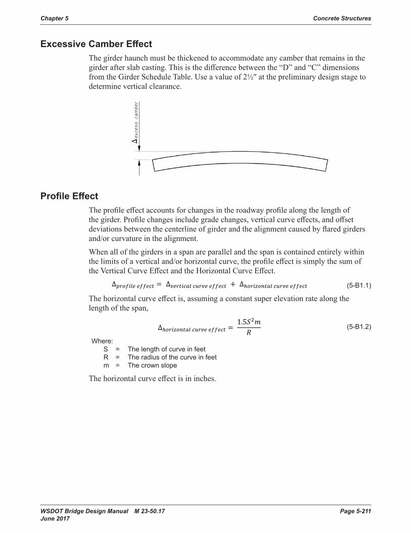
Chapter 5 Concrete Structures
WSDOT Bridge Design Manual M 23-50.17 Page 5-211 June 2017
Excessive Camber EffectThegirderhaunchmustbethickenedtoaccommodateanycamberthatremainsinthegirderafterslabcasting.Thisisthedifferencebetweenthe“D”and“C”dimensionsfromtheGirderScheduleTable.Useavalueof2½″atthepreliminarydesignstagetodetermine vertical clearance.
Excessive Camber Effect Thegirderhaunchmustbethickenedtoaccommodateanycamberthatremainsinthegirderafterslabcasting.Thisisthedifferencebetweenthe“D”and“C”dimensionsfromtheGirderScheduleTable.Useavalueof2 ½” at the preliminary design stage to determine vertical clearance.
Profile Effect The profile effect accounts for changes in the roadway profile along the length of the girder. Profile changes include grade changes, vertical curve effects, and offset deviations betweenthecenterlineofgirder and the alignment causedbyflaredgirdersand/orcurvature in the alignment.
When all of the girders in a span are parallel and the span is contained entirely within the limits of a vertical and/or horizontal curve, the profile effect is simply the sum of the Vertical Curve Effect and the Horizontal Curve Effect.
Profile EffectTheprofileeffectaccountsforchangesintheroadwayprofilealongthelengthofthegirder.Profilechangesincludegradechanges,verticalcurveeffects,andoffsetdeviationsbetweenthecenterlineofgirderandthealignmentcausedbyflaredgirdersand/or curvature in the alignment.
When all of the girders in a span are parallel and the span is contained entirely within thelimitsofaverticaland/orhorizontalcurve,theprofileeffectissimplythesumoftheVerticalCurveEffectandtheHorizontalCurveEffect.
5-B1.1 ∆������� ������ � ∆�������� ����� ������ � ∆���������� ����� ������
5-B1.2 ∆���������� ����� ������ � �������
5-B1.3 ∆ � ��
5-B1.4 � � ��
5-B1.5 � � �4�
5-B1.6 ���� � �
5-B1.7 ���� � 2��
5-B1.8 � � �2 ���� � �
2 � � �2 � �
4� � ����
5-B1.9 ∆���������� ����� ������ � ���� � � �2��
�� � ������ � ��������
5-B1.10 ∆�������� ����� ������ � �������
�00� � ��������
5-B1.10a � � �� � ��
5-B1.10b ��
5-B1.11 � � �00�2�
5-B1.12 ∆�������� ����� ������ � � ���
40,000 � �2���� � �
2� � ���
400 � �2 � �������
�00�
(5-B1 .1)
Thehorizontalcurveeffectis,assumingaconstantsuperelevationratealongthelength of the span,
5-B1.1 ∆������� ������ � ∆�������� ����� ������ � ∆���������� ����� ������
5-B1.2 ∆���������� ����� ������ � �������
5-B1.3 ∆ � ��
5-B1.4 � � ��
5-B1.5 � � �4�
5-B1.6 ���� � �
5-B1.7 ���� � 2��
5-B1.8 � � �2 ���� � �
2 � � �2 � �
4� � ����
5-B1.9 ∆���������� ����� ������ � ���� � � �2��
�� � ������ � ��������
5-B1.10 ∆�������� ����� ������ � �������
�00� � ��������
5-B1.10a � � �� � ��
5-B1.10b ��
5-B1.11 � � �00�2�
5-B1.12 ∆�������� ����� ������ � � ���
40,000 � �2���� � �
2� � ���
400 � �2 � �������
�00�
(5-B1 .2)
Where: S = The length of curve in feet R = The radius of the curve in feet m = The crown slope
Thehorizontalcurveeffectisininches.

Concrete Structures Chapter 5
Page 5-212 WSDOT Bridge Design Manual M 23-50.17 June 2017
effectcurvehorizontaleffectcurveverticaleffectprofile Δ+Δ=Δ
The horizontal curve effect is, assuming a constant super elevation rate along the length
of the span, R
mSeffectcurvehorizontal
25.1=Δ where S is the length of curve in feet, R is the
radius of the curve in feet, and m is the crown slope. The horizontal curve effect is in inches.
5-B1.1 ∆������� ������ � ∆�������� ����� ������ � ∆���������� ����� ������
5-B1.2 ∆���������� ����� ������ � �������
5-B1.3 ∆ � ��
5-B1.4 � � ��
5-B1.5 � � �4�
5-B1.6 ���� � �
5-B1.7 ���� � 2��
5-B1.8 � � �2 ���� � �
2 � � �2 � �
4� � ����
5-B1.9 ∆���������� ����� ������ � ���� � � �2��
�� � ������ � ��������
5-B1.10 ∆�������� ����� ������ � �������
�00� � ��������
5-B1.10a � � �� � ��
5-B1.10b ��
5-B1.11 � � �00�2�
5-B1.12 ∆�������� ����� ������ � � ���
40,000 � �2���� � �
2� � ���
400 � �2 � �������
�00�
(5-B1 .3)
5-B1.1 ∆������� ������ � ∆�������� ����� ������ � ∆���������� ����� ������
5-B1.2 ∆���������� ����� ������ � �������
5-B1.3 ∆ � ��
5-B1.4 � � ��
5-B1.5 � � �4�
5-B1.6 ���� � �
5-B1.7 ���� � 2��
5-B1.8 � � �2 ���� � �
2 � � �2 � �
4� � ����
5-B1.9 ∆���������� ����� ������ � ���� � � �2��
�� � ������ � ��������
5-B1.10 ∆�������� ����� ������ � �������
�00� � ��������
5-B1.10a � � �� � ��
5-B1.10b ��
5-B1.11 � � �00�2�
5-B1.12 ∆�������� ����� ������ � � ���
40,000 � �2���� � �
2� � ���
400 � �2 � �������
�00�
(5-B1 .4)
5-B1.1 ∆������� ������ � ∆�������� ����� ������ � ∆���������� ����� ������
5-B1.2 ∆���������� ����� ������ � �������
5-B1.3 ∆ � ��
5-B1.4 � � ��
5-B1.5 � � �4�
5-B1.6 ���� � �
5-B1.7 ���� � 2��
5-B1.8 � � �2 ���� � �
2 � � �2 � �
4� � ����
5-B1.9 ∆���������� ����� ������ � ���� � � �2��
�� � ������ � ��������
5-B1.10 ∆�������� ����� ������ � �������
�00� � ��������
5-B1.10a � � �� � ��
5-B1.10b ��
5-B1.11 � � �00�2�
5-B1.12 ∆�������� ����� ������ � � ���
40,000 � �2���� � �
2� � ���
400 � �2 � �������
�00�
(5-B1 .5)
5-B1.1 ∆������� ������ � ∆�������� ����� ������ � ∆���������� ����� ������
5-B1.2 ∆���������� ����� ������ � �������
5-B1.3 ∆ � ��
5-B1.4 � � ��
5-B1.5 � � �4�
5-B1.6 ���� � �
5-B1.7 ���� � 2��
5-B1.8 � � �2 ���� � �
2 � � �2 � �
4� � ����
5-B1.9 ∆���������� ����� ������ � ���� � � �2��
�� � ������ � ��������
5-B1.10 ∆�������� ����� ������ � �������
�00� � ��������
5-B1.10a � � �� � ��
5-B1.10b ��
5-B1.11 � � �00�2�
5-B1.12 ∆�������� ����� ������ � � ���
40,000 � �2���� � �
2� � ���
400 � �2 � �������
�00�
(5-B1 .6)
5-B1.1 ∆������� ������ � ∆�������� ����� ������ � ∆���������� ����� ������
5-B1.2 ∆���������� ����� ������ � �������
5-B1.3 ∆ � ��
5-B1.4 � � ��
5-B1.5 � � �4�
5-B1.6 ���� � �
5-B1.7 ���� � 2��
5-B1.8 � � �2 ���� � �
2 � � �2 � �
4� � ����
5-B1.9 ∆���������� ����� ������ � ���� � � �2��
�� � ������ � ��������
5-B1.10 ∆�������� ����� ������ � �������
�00� � ��������
5-B1.10a � � �� � ��
5-B1.10b ��
5-B1.11 � � �00�2�
5-B1.12 ∆�������� ����� ������ � � ���
40,000 � �2���� � �
2� � ���
400 � �2 � �������
�00�
(5-B1 .7)
5-B1.1 ∆������� ������ � ∆�������� ����� ������ � ∆���������� ����� ������
5-B1.2 ∆���������� ����� ������ � �������
5-B1.3 ∆ � ��
5-B1.4 � � ��
5-B1.5 � � �4�
5-B1.6 ���� � �
5-B1.7 ���� � 2��
5-B1.8 � � �2 ���� � �
2 � � �2 � �
4� � ����
5-B1.9 ∆���������� ����� ������ � ���� � � �2��
�� � ������ � ��������
5-B1.10 ∆�������� ����� ������ � �������
�00� � ��������
5-B1.10a � � �� � ��
5-B1.10b ��
5-B1.11 � � �00�2�
5-B1.12 ∆�������� ����� ������ � � ���
40,000 � �2���� � �
2� � ���
400 � �2 � �������
�00�
(5-B1 .8)
5-B1.1 ∆������� ������ � ∆�������� ����� ������ � ∆���������� ����� ������
5-B1.2 ∆���������� ����� ������ � �������
5-B1.3 ∆ � ��
5-B1.4 � � ��
5-B1.5 � � �4�
5-B1.6 ���� � �
5-B1.7 ���� � 2��
5-B1.8 � � �2 ���� � �
2 � � �2 � �
4� � ����
5-B1.9 ∆���������� ����� ������ � ���� � � �2��
�� � ������ � ��������
5-B1.10 ∆�������� ����� ������ � �������
�00� � ��������
5-B1.10a � � �� � ��
5-B1.10b ��
5-B1.11 � � �00�2�
5-B1.12 ∆�������� ����� ������ � � ���
40,000 � �2���� � �
2� � ���
400 � �2 � �������
�00�
(5-B1 .9)

Chapter 5 Concrete Structures
WSDOT Bridge Design Manual M 23-50.17 Page 5-213 June 2017
Theverticalcurveeffectis
5-B1.1 ∆������� ������ � ∆�������� ����� ������ � ∆���������� ����� ������
5-B1.2 ∆���������� ����� ������ � �������
5-B1.3 ∆ � ��
5-B1.4 � � ��
5-B1.5 � � �4�
5-B1.6 ���� � �
5-B1.7 ���� � 2��
5-B1.8 � � �2 ���� � �
2 � � �2 � �
4� � ����
5-B1.9 ∆���������� ����� ������ � ���� � � �2��
�� � ������ � ��������
5-B1.10 ∆�������� ����� ������ � �������
�00� � ��������
5-B1.10a � � �� � ��
5-B1.10b ��
5-B1.11 � � �00�2�
5-B1.12 ∆�������� ����� ������ � � ���
40,000 � �2���� � �
2� � ���
400 � �2 � �������
�00�
(5-B1 .10)
Where: G = The algebraic difference in profile tangent grades
5-B1.1 ∆������� ������ � ∆�������� ����� ������ � ∆���������� ����� ������
5-B1.2 ∆���������� ����� ������ � �������
5-B1.3 ∆ � ��
5-B1.4 � � ��
5-B1.5 � � �4�
5-B1.6 ���� � �
5-B1.7 ���� � 2��
5-B1.8 � � �2 ���� � �
2 � � �2 � �
4� � ����
5-B1.9 ∆���������� ����� ������ � ���� � � �2��
�� � ������ � ��������
5-B1.10 ∆�������� ����� ������ � �������
�00� � ��������
5-B1.10a � � �� � ��
5-B1.10b ��
5-B1.11 � � �00�2�
5-B1.12 ∆�������� ����� ������ � � ���
40,000 � �2���� � �
2� � ���
400 � �2 � �������
�00�
(%)
5-B1.1 ∆������� ������ � ∆�������� ����� ������ � ∆���������� ����� ������
5-B1.2 ∆���������� ����� ������ � �������
5-B1.3 ∆ � ��
5-B1.4 � � ��
5-B1.5 � � �4�
5-B1.6 ���� � �
5-B1.7 ���� � 2��
5-B1.8 � � �2 ���� � �
2 � � �2 � �
4� � ����
5-B1.9 ∆���������� ����� ������ � ���� � � �2��
�� � ������ � ��������
5-B1.10 ∆�������� ����� ������ � �������
�00� � ��������
5-B1.10a � � �� � ��
5-B1.10b ��
5-B1.11 � � �00�2�
5-B1.12 ∆�������� ����� ������ � � ���
40,000 � �2���� � �
2� � ���
400 � �2 � �������
�00�
= The girder length in feet L = The vertical curve length in feet
Theverticalcurveeffectisininchesandispositiveforsagcurvesandnegativeforcrown curves.
( )inchesmRSm
RS
RS
RSSSSH
SH
RS
RS
ftin
effectcurvehorizontal
22
2
5.1128
8422tan
2
2tan
tan4
4
=×=Δ
=×=≈=
≈
≈
=
Δ=
=Δ
φφ
φ
φφ
φ
φ
The vertical curve effect is L
GLgeffectcurvevertical 100
5.1 2
=Δ where Gisthealgebraicdifference
in profile tangent grades (G = g2 - g1) (%), Lg is the girder length (feet), and L is the vertical curve length (feet). The vertical curve effect is in inches and is positive for sag curves and negative for crown curves.
LGLL
LGL
K
LGK
ggfting
effectcurvevertical 1005.1
124002
12000,40
2100
222
=××=×=Δ
=
If one or more of the following roadway geometry transitions occur along the span, then a more detailed method of computationisrequired:
• change in the super elevation rate • gradebreak• point of horizontal curvature • point of vertical curvature • flared girders
5-B1.1 ∆������� ������ � ∆�������� ����� ������ � ∆���������� ����� ������
5-B1.2 ∆���������� ����� ������ � �������
5-B1.3 ∆ � ��
5-B1.4 � � ��
5-B1.5 � � �4�
5-B1.6 ���� � �
5-B1.7 ���� � 2��
5-B1.8 � � �2 ���� � �
2 � � �2 � �
4� � ����
5-B1.9 ∆���������� ����� ������ � ���� � � �2��
�� � ������ � ��������
5-B1.10 ∆�������� ����� ������ � �������
�00� � ��������
5-B1.10a � � �� � ��
5-B1.10b ��
5-B1.11 � � �00�2�
5-B1.12 ∆�������� ����� ������ � � ���
40,000 � �2���� � �
2� � ���
400 � �2 � �������
�00�
(5-B1 .11)
5-B1.1 ∆������� ������ � ∆�������� ����� ������ � ∆���������� ����� ������
5-B1.2 ∆���������� ����� ������ � �������
5-B1.3 ∆ � ��
5-B1.4 � � ��
5-B1.5 � � �4�
5-B1.6 ���� � �
5-B1.7 ���� � 2��
5-B1.8 � � �2 ���� � �
2 � � �2 � �
4� � ����
5-B1.9 ∆���������� ����� ������ � ���� � � �2��
�� � ������ � ��������
5-B1.10 ∆�������� ����� ������ � �������
�00� � ��������
5-B1.10a � � �� � ��
5-B1.10b ��
5-B1.11 � � �00�2�
5-B1.12 ∆�������� ����� ������ � � ���
40,000 � �2���� � �
2� � ���
400 � �2 � �������
�00� (5-B1 .12)
If one or more of the following roadway geometry transitions occur along the span, thenamoredetailedmethodofcomputationisrequired:• Change in the super elevation rate• Gradebreak• Point of horizontal curvature• Point of vertical curvature• Flared girders
Theexactvalueoftheprofileeffectmaybedeterminedbysolvingacomplexoptimizationproblem.Howeveritismucheasierandsufficientlyaccuratetouseanumerical approach.
Thefigurebelow,whilehighlyexaggerated,illustratesthattheprofileeffectisthedistancethegirdermustbeplacedbelowtheprofilegradesothatthegirder,ignoringallothergeometriceffects,justtouchesthelowestprofilepointbetweenthebearings.
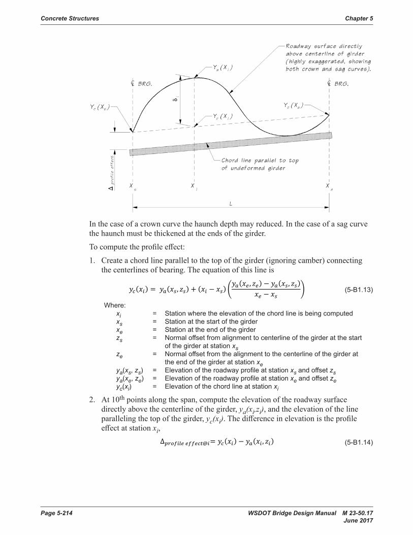
Concrete Structures Chapter 5
Page 5-214 WSDOT Bridge Design Manual M 23-50.17 June 2017
The exact value of the profile effect maybedeterminedbysolvingacomplexoptimizationproblem.Howeveritismucheasier and sufficiently accurate to use a numerical approach.
Thefigurebelow,whilehighlyexaggerated,illustrates that the profile effect is the distancethegirdermustbeplacedbelowtheprofile grade so that the girder, ignoring all other geometric effects, just touches the lowestprofilepointbetweenthebearings.
In the case of a crown curve the haunch depth may reduced. In the case of a sag curve the haunchmustbethickenedattheendsofthegirder.
Tocomputetheprofileeffect:1. Create a chord line parallel to the top of the girder (ignoringcamber)connecting
thecenterlinesofbearing.The equation of this line is
( ) ( ) ( ) ( ) ( )⎟⎟⎠
⎞⎜⎜⎝
⎛−−
−+=se
ssaeeasissaic xx
zxyzxyxxzxyxy ,,,
wherexi = Stationwheretheelevationofthechordlineisbeingcomputedxs = Station at the start of the girder xe = Station at the end of the girder zs = Normal offset from alignment to centerline of the girder at the
start of the girder at station xsze = Normal offset from the alignment to the centerline of the girder
at the end of the girder at station xeya(xs,zs) = Elevation of the roadway profile at station xs and offset zs
In the case of a crown curve the haunch depth may reduced. In the case of a sag curve thehaunchmustbethickenedattheendsofthegirder.
Tocomputetheprofileeffect:
1. Createachordlineparalleltothetopofthegirder(ignoringcamber)connectingthecenterlinesofbearing.Theequationofthislineis
5-B1.13 ������ � �����, ��� � ��� � ��� ������, ��� � �����, ����� � ��
�
5-B1.14
5-B1.15 ∆������ ����������� ������� ∆��� ����� ������� � �����2 �
5-B1.16 ����, ��� � �����, ������� � �����, ��
��������
���� � �������
5-B1.16a ������
5-B1.16b �������
5-B1.16c �����, �������
5-B1.16d �����, ��������
5-B1.17 �� � ����� �� � � ��
�� � �����
5-B1.18 � � ∆������ � ∆������ ������ � ∆������� ������ � ∆������ ����������� ������
5-B1.19 ���� � ∆������ � ∆������ ����������� ������
5-B1.21 � � ∆������� ������ � ∆������ ������
5-B1.ADimWkSht1 ∆������� ����� � �������
5-B1.ADimWkSht2 ∆������ ������ � ��� � ���
(5-B1 .13)
Where: xi = Station where the elevation of the chord line is being computed xs = Station at the start of the girder xe = Station at the end of the girder zs = Normal offset from alignment to centerline of the girder at the start of the girder at station xs ze = Normal offset from the alignment to the centerline of the girder at the end of the girder at station xe ya(xs, zs) = Elevation of the roadway profile at station xs and offset zs ya(xe, ze) = Elevation of the roadway profile at station xe and offset ze yc(xi) = Elevation of the chord line at station xi
2. At 10th points along the span, compute the elevation of the roadway surface directlyabovethecenterlineofthegirder,ya(xi,zi), and the elevation of the line paralleling the top of the girder, yc(xi).Thedifferenceinelevationistheprofileeffectatstationxi,
5-B1.13 ������ � �����, ��� � ��� � ��� ������, ��� � �����, ����� � ��
�
5-B1.14 ∆������� ��������� ������ � �����, ���
5-B1.15 ∆������ ����������� ������� ∆��� ����� ������� � �����2 �
5-B1.16 ����, ��� � �����, ������� � �����, ��
��������
���� � �������
5-B1.16a ������
5-B1.16b �������
5-B1.16c �����, �������
5-B1.16d �����, ��������
5-B1.17 �� � ����� �� � � ��
�� � �����
5-B1.18 � � ∆������ � ∆������ ������ � ∆������� ������ � ∆������ ����������� ������
5-B1.19 ���� � ∆������ � ∆������ ����������� ������
5-B1.21 � � ∆������� ������ � ∆������ ������
5-B1.ADimWkSht1 ∆������� ����� � �������
5-B1.ADimWkSht2 ∆������ ������ � ��� � ���
(5-B1 .14)
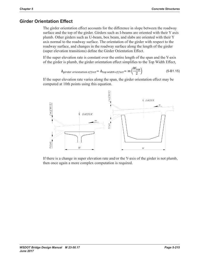
Chapter 5 Concrete Structures
WSDOT Bridge Design Manual M 23-50.17 Page 5-215 June 2017
Girder Orientation EffectThegirderorientationeffectaccountsforthedifferenceinslopebetweentheroadwaysurfaceandthetopofthegirder.GirderssuchasI-beamsareorientedwiththeirYaxisplumb.OthergirderssuchasU-beam,boxbeam,andslabsareorientedwiththeirYaxis normal to the roadway surface. The orientation of the girder with respect to the roadway surface, and changes in the roadway surface along the length of the girder (superelevationtransitions)definetheGirderOrientationEffect.
If the super elevation rate is constant over the entire length of the span and the Y-axis ofthegirderisplumb,thegirderorientationeffectsimplifiestotheTopWidthEffect,
5-B1.13 ������ � �����, ��� � ��� � ��� ������, ��� � �����, ����� � ��
�
5-B1.14 ∆������� ��������� ������ � �����, ���
5-B1.15 ∆������ ����������� ������� ∆��� ����� ������� � �����2 �
5-B1.16 ����, ��� � �����, ������� � �����, ��
��������
���� � �������
5-B1.16a ������
5-B1.16b �������
5-B1.16c �����, �������
5-B1.16d �����, ��������
5-B1.17 �� � ����� �� � � ��
�� � �����
5-B1.18 � � ∆������ � ∆������ ������ � ∆������� ������ � ∆������ ����������� ������
5-B1.19 ���� � ∆������ � ∆������ ����������� ������
5-B1.21 � � ∆������� ������ � ∆������ ������
5-B1.ADimWkSht1 ∆������� ����� � �������
5-B1.ADimWkSht2 ∆������ ������ � ��� � ���
(5-B1 .15)
Ifthesuperelevationratevariesalongthespan,thegirderorientationeffectmaybecomputed at 10th points using this equation.
ya(xe,ze) = Elevation of the roadway profile at station xe and offset zeyc(xi) = Elevation of the chord line at station xi
2. At 10th points along the span, compute the elevation of the roadway surface directlyabovethecenterlineofthegirder,ya(xi,zi), and the elevation of the line paralleling the top of the girder, yc(xi). The difference in elevation is the profile effect at station xi, ( ) ( )iciiaieffectprofile xyzxy −=Δ ,@ .
Girder Orientation Effect The girder orientation effect accounts for thedifferenceinslopebetweentheroadwaysurface and the top of the girder. Girders such asI-beamsareorientedwiththeirYaxisplumb.OthergirderssuchasU-beam,boxbeam,andslabsareorientedwiththeirYaxisnormal to the roadway surface. The orientation of the girder with respect to the roadway surface, and changes in the roadway surface along the length of the girder (super elevation transitions) define the Girder Orientation Effect.
If the super elevation rate is constant over the entire length of the span and the Y-axis of thegirderisplumb,thegirderorientation effect simplifies to the Top Width Effect,
⎟⎟⎠
⎞⎜⎜⎝
⎛=Δ=Δ
2top
effectwidthtopeffectnorientatiogirder
Wm .
If there is a change in super elevation rate and/or the Y-axisofthegirderisnotplumb,then once again a more complex computation is required. Ifthereisachangeinsuperelevationrateand/ortheY-axisofthegirderisnotplumb,then once again a more complex computation is required.
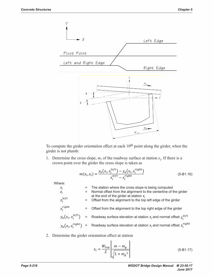
Concrete Structures Chapter 5
Page 5-216 WSDOT Bridge Design Manual M 23-50.17 June 2017
To compute the girder orientation effect at each 10thpointalongthegirder:1. Determine the cross slope, m, of the roadway surface at station xi. If there is a
crown point over the girder the cross slope is taken as
( ) ( ) ( )righti
lefti
rightiia
leftiia
ii zzzxyzxy
zxm−−
=,,
,
where
xi = The station where the crossslopeisbeingcomputedzi = Normal offset from the alignment to the centerline of the girder
at the end of the girder at station xizi
left = Offset from the alignment to the top left edge of the girder zi
right = Offset from the alignment to the top right edge of the girder ya(xi,zi
left) = Roadway surface elevation at station xi and normal offset zileft
ya(xi,ziright) = Roadway surface elevation at station xi and normal offset zi
right
Tocomputethegirderorientationeffectateach10th point along the girder, when the girderisnotplumb:
1. Determine the cross slope, m, of the roadway surface at station xi. If there is a crown point over the girder the cross slope is taken as
5-B1.13 ������ � �����, ��� � ��� � ��� ������, ��� � �����, ����� � ��
�
5-B1.14 ∆������� ��������� ������ � �����, ���
5-B1.15 ∆������ ����������� ������� ∆��� ����� ������� � �����2 �
5-B1.16 ����, ��� � �����, ������� � �����, ��
��������
���� � �������
5-B1.16a ������
5-B1.16b �������
5-B1.16c �����, �������
5-B1.16d �����, ��������
5-B1.17 �� � ����� �� � � ��
�� � �����
5-B1.18 � � ∆������ � ∆������ ������ � ∆������� ������ � ∆������ ����������� ������
5-B1.19 ���� � ∆������ � ∆������ ����������� ������
5-B1.21 � � ∆������� ������ � ∆������ ������
5-B1.ADimWkSht1 ∆������� ����� � �������
5-B1.ADimWkSht2 ∆������ ������ � ��� � ���
(5-B1 .16)
Where: xi = The station where the cross slope is being computed zi = Normal offset from the alignment to the centerline of the girder at the end of the girder at station xi
5-B1.13 ������ � �����, ��� � ��� � ��� ������, ��� � �����, ����� � ��
�
5-B1.14 ∆������� ��������� ������ � �����, ���
5-B1.15 ∆������ ����������� ������� ∆��� ����� ������� � �����2 �
5-B1.16 ����, ��� � �����, ������� � �����, ��
��������
���� � �������
5-B1.16a ������
5-B1.16b �������
5-B1.16c �����, �������
5-B1.16d �����, ��������
5-B1.17 �� � ����� �� � � ��
�� � �����
5-B1.18 � � ∆������ � ∆������ ������ � ∆������� ������ � ∆������ ����������� ������
5-B1.19 ���� � ∆������ � ∆������ ����������� ������
5-B1.21 � � ∆������� ������ � ∆������ ������
5-B1.ADimWkSht1 ∆������� ����� � �������
5-B1.ADimWkSht2 ∆������ ������ � ��� � ���
= Offset from the alignment to the top left edge of the girder
5-B1.13 ������ � �����, ��� � ��� � ��� ������, ��� � �����, ����� � ��
�
5-B1.14 ∆������� ��������� ������ � �����, ���
5-B1.15 ∆������ ����������� ������� ∆��� ����� ������� � �����2 �
5-B1.16 ����, ��� � �����, ������� � �����, ��
��������
���� � �������
5-B1.16a ������
5-B1.16b �������
5-B1.16c �����, �������
5-B1.16d �����, ��������
5-B1.17 �� � ����� �� � � ��
�� � �����
5-B1.18 � � ∆������ � ∆������ ������ � ∆������� ������ � ∆������ ����������� ������
5-B1.19 ���� � ∆������ � ∆������ ����������� ������
5-B1.21 � � ∆������� ������ � ∆������ ������
5-B1.ADimWkSht1 ∆������� ����� � �������
5-B1.ADimWkSht2 ∆������ ������ � ��� � ���
= Offset from the alignment to the top right edge of the girder
5-B1.13 ������ � �����, ��� � ��� � ��� ������, ��� � �����, ����� � ��
�
5-B1.14 ∆������� ��������� ������ � �����, ���
5-B1.15 ∆������ ����������� ������� ∆��� ����� ������� � �����2 �
5-B1.16 ����, ��� � �����, ������� � �����, ��
��������
���� � �������
5-B1.16a ������
5-B1.16b �������
5-B1.16c �����, �������
5-B1.16d �����, ��������
5-B1.17 �� � ����� �� � � ��
�� � �����
5-B1.18 � � ∆������ � ∆������ ������ � ∆������� ������ � ∆������ ����������� ������
5-B1.19 ���� � ∆������ � ∆������ ����������� ������
5-B1.21 � � ∆������� ������ � ∆������ ������
5-B1.ADimWkSht1 ∆������� ����� � �������
5-B1.ADimWkSht2 ∆������ ������ � ��� � ���
= Roadway surface elevation at station xi and normal offset
5-B1.13 ������ � �����, ��� � ��� � ��� ������, ��� � �����, ����� � ��
�
5-B1.14 ∆������� ��������� ������ � �����, ���
5-B1.15 ∆������ ����������� ������� ∆��� ����� ������� � �����2 �
5-B1.16 ����, ��� � �����, ������� � �����, ��
��������
���� � �������
5-B1.16a ������
5-B1.16b �������
5-B1.16c �����, �������
5-B1.16d �����, ��������
5-B1.17 �� � ����� �� � � ��
�� � �����
5-B1.18 � � ∆������ � ∆������ ������ � ∆������� ������ � ∆������ ����������� ������
5-B1.19 ���� � ∆������ � ∆������ ����������� ������
5-B1.21 � � ∆������� ������ � ∆������ ������
5-B1.ADimWkSht1 ∆������� ����� � �������
5-B1.ADimWkSht2 ∆������ ������ � ��� � ���
= Roadway surface elevation at station xi and normal offset
5-B1.13 ������ � �����, ��� � ��� � ��� ������, ��� � �����, ����� � ��
�
5-B1.14 ∆������� ��������� ������ � �����, ���
5-B1.15 ∆������ ����������� ������� ∆��� ����� ������� � �����2 �
5-B1.16 ����, ��� � �����, ������� � �����, ��
��������
���� � �������
5-B1.16a ������
5-B1.16b �������
5-B1.16c �����, �������
5-B1.16d �����, ��������
5-B1.17 �� � ����� �� � � ��
�� � �����
5-B1.18 � � ∆������ � ∆������ ������ � ∆������� ������ � ∆������ ����������� ������
5-B1.19 ���� � ∆������ � ∆������ ����������� ������
5-B1.21 � � ∆������� ������ � ∆������ ������
5-B1.ADimWkSht1 ∆������� ����� � �������
5-B1.ADimWkSht2 ∆������ ������ � ��� � ���
2. Determinethegirderorientationeffectatstation
5-B1.13 ������ � �����, ��� � ��� � ��� ������, ��� � �����, ����� � ��
�
5-B1.14 ∆������� ��������� ������ � �����, ���
5-B1.15 ∆������ ����������� ������� ∆��� ����� ������� � �����2 �
5-B1.16 ����, ��� � �����, ������� � �����, ��
��������
���� � �������
5-B1.16a ������
5-B1.16b �������
5-B1.16c �����, �������
5-B1.16d �����, ��������
5-B1.17 �� � ����� �� � � ��
�� � �����
5-B1.18 � � ∆������ � ∆������ ������ � ∆������� ������ � ∆������ ����������� ������
5-B1.19 ���� � ∆������ � ∆������ ����������� ������
5-B1.21 � � ∆������� ������ � ∆������ ������
5-B1.ADimWkSht1 ∆������� ����� � �������
5-B1.ADimWkSht2 ∆������ ������ � ��� � ���
(5-B1 .17)
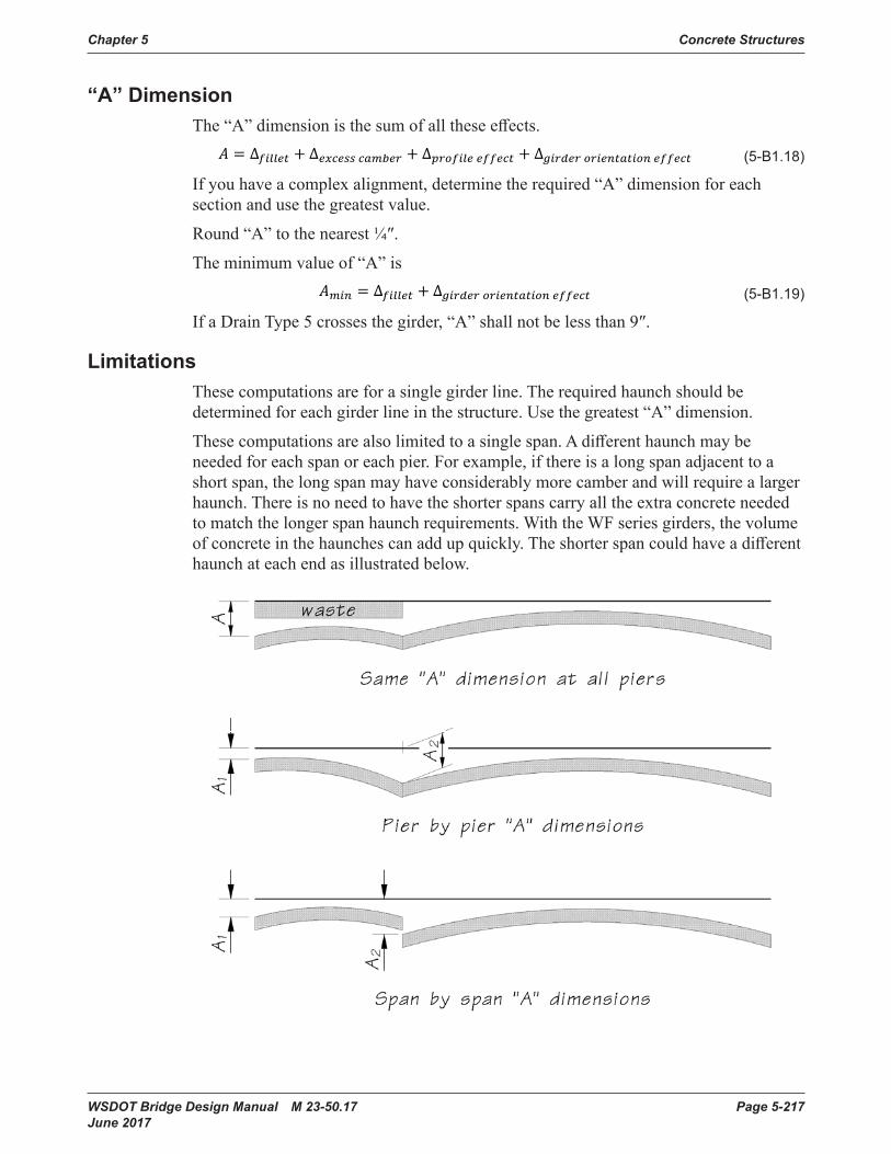
Chapter 5 Concrete Structures
WSDOT Bridge Design Manual M 23-50.17 Page 5-217 June 2017
“A” DimensionThe“A”dimensionisthesumofalltheseeffects.
5-B1.13 ������ � �����, ��� � ��� � ��� ������, ��� � �����, ����� � ��
�
5-B1.14 ∆������� ��������� ������ � �����, ���
5-B1.15 ∆������ ����������� ������� ∆��� ����� ������� � �����2 �
5-B1.16 ����, ��� � �����, ������� � �����, ��
��������
���� � �������
5-B1.16a ������
5-B1.16b �������
5-B1.16c �����, �������
5-B1.16d �����, ��������
5-B1.17 �� � ����� �� � � ��
�� � �����
5-B1.18 � � ∆������ � ∆������ ������ � ∆������� ������ � ∆������ ����������� ������
5-B1.19 ���� � ∆������ � ∆������ ����������� ������
5-B1.21 � � ∆������� ������ � ∆������ ������
5-B1.ADimWkSht1 ∆������� ����� � �������
5-B1.ADimWkSht2 ∆������ ������ � ��� � ���
(5-B1 .18)
If you have a complex alignment, determine the required “A” dimension for each section and use the greatest value.
Round“A”tothenearest¼″.
The minimum value of “A” is
5-B1.13 ������ � �����, ��� � ��� � ��� ������, ��� � �����, ����� � ��
�
5-B1.14 ∆������� ��������� ������ � �����, ���
5-B1.15 ∆������ ����������� ������� ∆��� ����� ������� � �����2 �
5-B1.16 ����, ��� � �����, ������� � �����, ��
��������
���� � �������
5-B1.16a ������
5-B1.16b �������
5-B1.16c �����, �������
5-B1.16d �����, ��������
5-B1.17 �� � ����� �� � � ��
�� � �����
5-B1.18 � � ∆������ � ∆������ ������ � ∆������� ������ � ∆������ ����������� ������
5-B1.19 ���� � ∆������ � ∆������ ����������� ������
5-B1.21 � � ∆������� ������ � ∆������ ������
5-B1.ADimWkSht1 ∆������� ����� � �������
5-B1.ADimWkSht2 ∆������ ������ � ��� � ���
(5-B1 .19)
IfaDrainType5crossesthegirder,“A”shallnotbelessthan9″.
LimitationsThesecomputationsareforasinglegirderline.Therequiredhaunchshouldbedetermined for each girder line in the structure. Use the greatest “A” dimension.
Thesecomputationsarealsolimitedtoasinglespan.Adifferenthaunchmaybeneeded for each span or each pier. For example, if there is a long span adjacent to a shortspan,thelongspanmayhaveconsiderablymorecamberandwillrequirealargerhaunch. There is no need to have the shorter spans carry all the extra concrete needed to match the longer span haunch requirements. With the WF series girders, the volume ofconcreteinthehaunchescanaddupquickly.Theshorterspancouldhaveadifferenthaunchateachendasillustratedbelow.
Stirrup Length and Precast Deck Leveling Bolt ConsiderationsForbridgesoncrownverticalcurves,thehaunchdepthcanbecomeexcessivetothepointwhere the girder and diaphragm stirrups are tooshorttobendintothe proper position. Similarlythelengthoflevelingboltsinprecast deck panels may need adjustment.
Stirruplengthsaredescribedasafunctionof “A” on the standard girder sheets. For example,theG1andG2barsofaWF74Ggirderare6’-5”+“A”inlength.Forthisreason, the stirrups are always long enough attheendsofthegirders.Problemsoccurwhen the haunch depth increases along the length of the girder to accommodate crown vertical curves and super elevation transitions.
Ifthehaunchdepthalongthegirderexceeds“A”bymorethan2inches,anadjustmentmustbemade.Thehaunchdepthatanysectioncanbecomputeas camberexcesseffectprofileA Δ−Δ− .

Concrete Structures Chapter 5
Page 5-218 WSDOT Bridge Design Manual M 23-50.17 June 2017
Stirrup Length and Precast Deck Leveling Bolt ConsiderationsForbridgesoncrownverticalcurves,thehaunchdepthcanbecomeexcessivetothepointwherethegirderanddiaphragmstirrupsaretooshorttobendintotheproperposition.Similarlythelengthoflevelingboltsinprecastdeckpanelsmayneed adjustment.
Stirruplengthsaredescribedasafunctionof“A”onthestandardgirdersheets.Forexample,theG1andG2barsofaWF74Ggirderare6′-5″+“A”inlength.Forthisreason,thestirrupsarealwayslongenoughattheendsofthegirders.Problemsoccurwhen the haunch depth increases along the length of the girder to accommodate crown vertical curves and super elevation transitions.
Ifthehaunchdepthalongthegirderexceeds“A”bymorethan2″, an adjustment must bemade.Thehaunchdepthatanysectioncanbecomputeas
5-B1.13 ������ � �����, ��� � ��� � ��� ������, ��� � �����, ����� � ��
�
5-B1.14 ∆������� ��������� ������ � �����, ���
5-B1.15 ∆������ ����������� ������� ∆��� ����� ������� � �����2 �
5-B1.16 ����, ��� � �����, ������� � �����, ��
��������
���� � �������
5-B1.16a ������
5-B1.16b �������
5-B1.16c �����, �������
5-B1.16d �����, ��������
5-B1.17 �� � ����� �� � � ��
�� � �����
5-B1.18 � � ∆������ � ∆������ ������ � ∆������� ������ � ∆������ ����������� ������
5-B1.19 ���� � ∆������ � ∆������ ����������� ������
5-B1.21 � � ∆������� ������ � ∆������ ������
5-B1.ADimWkSht1 ∆������� ����� � �������
5-B1.ADimWkSht2 ∆������ ������ � ��� � ���
(5-B1 .20)
“A” Dimension Worksheet–Simple AlignmentFilletEffect
SlabThickness(tslab) = ______ in Fillet Size (tfillet) = ______ in
5-B1.13 ������ � �����, ��� � ��� � ��� ������, ��� � �����, ����� � ��
�
5-B1.14 ∆������� ��������� ������ � �����, ���
5-B1.15 ∆������ ����������� ������� ∆��� ����� ������� � �����2 �
5-B1.16 ����, ��� � �����, ������� � �����, ��
��������
���� � �������
5-B1.16a ������
5-B1.16b �������
5-B1.16c �����, �������
5-B1.16d �����, ��������
5-B1.17 �� � ����� �� � � ��
�� � �����
5-B1.18 � � ∆������ � ∆������ ������ � ∆������� ������ � ∆������ ����������� ������
5-B1.19 ���� � ∆������ � ∆������ ����������� ������
5-B1.21 � � ∆������� ������ � ∆������ ������
5-B1.ADimWkSht1 ∆������� ����� � �������
5-B1.ADimWkSht2 ∆������ ������ � ��� � ���
= ______ in
ExcessCamberEffect
“D” Dimension from Girder Schedule (120 days) = ______ in “C” Dimension from Girder Schedule = ______ in
5-B1.13 ������ � �����, ��� � ��� � ��� ������, ��� � �����, ����� � ��
�
5-B1.14 ∆������� ��������� ������ � �����, ���
5-B1.15 ∆������ ����������� ������� ∆��� ����� ������� � �����2 �
5-B1.16 ����, ��� � �����, ������� � �����, ��
��������
���� � �������
5-B1.16a ������
5-B1.16b �������
5-B1.16c �����, �������
5-B1.16d �����, ��������
5-B1.17 �� � ����� �� � � ��
�� � �����
5-B1.18 � � ∆������ � ∆������ ������ � ∆������� ������ � ∆������ ����������� ������
5-B1.19 ���� � ∆������ � ∆������ ����������� ������
5-B1.21 � � ∆������� ������ � ∆������ ������
5-B1.ADimWkSht1 ∆������� ����� � �������
5-B1.ADimWkSht2 ∆������ ������ � ��� � ��� = ______ in
ProfileEffect
HorizontalCurveEffect,5-B1.ADimWkSht3 ∆���������� ����� ������ � 1.5����
5-B1.ADimWkSht4 ∆�������� ����� ������ � 1.5����
100�
5-B1.ADimWkSht5 ∆�������� ∆���������� ����� ������ � ∆�������� ����� ������
5-B1.ADimWkSht6 ∆������ ������������ 0 forU-beamsinclined paralleltotheslab
5-B1.ADimWkSht7 ∆������ ������������ ∆��� ������ ������� � �����2 �
5-B1.ADimWkSht8 ∆������ � ∆������ ������ � ∆������� ������ � ∆������ ����������� ������
5-B1.ADimWkSht9 ∆������ � ∆������ ����������� ������
5-B1.Example1 ∆������� ����� � �������
5-B1.Example2 ∆������ ������ � ��� � ���
5-B1.Example3 � 144.4��� � � 2����∆� 144.4 � 2�9500����∆
� � � 0.87�
5-B1.Example4 � �∆ �180 � 9500�0.87� �
180 � 144.4��
5-B1.Example5 ∆���������� ����� ������� 1.5���� � 1.5�144.4�� 0.04
9500 � 0.1��
5-B1.Example6 ∆�������� ����� ������ � 1.5����
100� � 1.5��5.����144.4��100�800� � �2.19�
5-B1.Example7 ∆������� � ∆���������� ����� �������∆�������� ����� ������ � 0.1� � 2.19 � �2.0��
= ______ in
VerticalCurveEffect,
5-B1.ADimWkSht3 ∆���������� ����� ������ � 1.5����
5-B1.ADimWkSht4 ∆�������� ����� ������ � 1.5����
100�
5-B1.ADimWkSht5 ∆�������� ∆���������� ����� ������ � ∆�������� ����� ������
5-B1.ADimWkSht6 ∆������ ������������ 0 forU-beamsinclined paralleltotheslab
5-B1.ADimWkSht7 ∆������ ������������ ∆��� ������ ������� � �����2 �
5-B1.ADimWkSht8 ∆������ � ∆������ ������ � ∆������� ������ � ∆������ ����������� ������
5-B1.ADimWkSht9 ∆������ � ∆������ ����������� ������
5-B1.Example1 ∆������� ����� � �������
5-B1.Example2 ∆������ ������ � ��� � ���
5-B1.Example3 � 144.4��� � � 2����∆� 144.4 � 2�9500����∆
� � � 0.87�
5-B1.Example4 � �∆ �180 � 9500�0.87� �
180 � 144.4��
5-B1.Example5 ∆���������� ����� ������� 1.5���� � 1.5�144.4�� 0.04
9500 � 0.1��
5-B1.Example6 ∆�������� ����� ������ � 1.5����
100� � 1.5��5.����144.4��100�800� � �2.19�
5-B1.Example7 ∆������� � ∆���������� ����� �������∆�������� ����� ������ � 0.1� � 2.19 � �2.0��
= ______ in (+ for sag, – for crown)
5-B1.ADimWkSht3 ∆���������� ����� ������ � 1.5����
5-B1.ADimWkSht4 ∆�������� ����� ������ � 1.5����
100�
5-B1.ADimWkSht5 ∆�������� ∆���������� ����� ������ � ∆�������� ����� ������
5-B1.ADimWkSht6 ∆������ ������������ 0 forU-beamsinclined paralleltotheslab
5-B1.ADimWkSht7 ∆������ ������������ ∆��� ������ ������� � �����2 �
5-B1.ADimWkSht8 ∆������ � ∆������ ������ � ∆������� ������ � ∆������ ����������� ������
5-B1.ADimWkSht9 ∆������ � ∆������ ����������� ������
5-B1.Example1 ∆������� ����� � �������
5-B1.Example2 ∆������ ������ � ��� � ���
5-B1.Example3 � 144.4��� � � 2����∆� 144.4 � 2�9500����∆
� � � 0.87�
5-B1.Example4 � �∆ �180 � 9500�0.87� �
180 � 144.4��
5-B1.Example5 ∆���������� ����� ������� 1.5���� � 1.5�144.4�� 0.04
9500 � 0.1��
5-B1.Example6 ∆�������� ����� ������ � 1.5����
100� � 1.5��5.����144.4��100�800� � �2.19�
5-B1.Example7 ∆������� � ∆���������� ����� �������∆�������� ����� ������ � 0.1� � 2.19 � �2.0��
= ______ in
GirderOrientationEffect Girdermustbeplumb.
5-B1.ADimWkSht3 ∆���������� ����� ������ � 1.5����
5-B1.ADimWkSht4 ∆�������� ����� ������ � 1.5����
100�
5-B1.ADimWkSht5 ∆�������� ∆���������� ����� ������ � ∆�������� ����� ������
5-B1.ADimWkSht6 ∆������ ������������ 0 forU-beamsinclined paralleltotheslab
5-B1.ADimWkSht7 ∆������ ������������ ∆��� ������ ������� � �����2 �
5-B1.ADimWkSht8 ∆������ � ∆������ ������ � ∆������� ������ � ∆������ ����������� ������
5-B1.ADimWkSht9 ∆������ � ∆������ ����������� ������
5-B1.Example1 ∆������� ����� � �������
5-B1.Example2 ∆������ ������ � ��� � ���
5-B1.Example3 � 144.4��� � � 2����∆� 144.4 � 2�9500����∆
� � � 0.87�
5-B1.Example4 � �∆ �180 � 9500�0.87� �
180 � 144.4��
5-B1.Example5 ∆���������� ����� ������� 1.5���� � 1.5�144.4�� 0.04
9500 � 0.1��
5-B1.Example6 ∆�������� ����� ������ � 1.5����
100� � 1.5��5.����144.4��100�800� � �2.19�
5-B1.Example7 ∆������� � ∆���������� ����� �������∆�������� ����� ������ � 0.1� � 2.19 � �2.0��
= ______ in
“A” Dimension
5-B1.ADimWkSht3 ∆���������� ����� ������ � 1.5����
5-B1.ADimWkSht4 ∆�������� ����� ������ � 1.5����
100�
5-B1.ADimWkSht5 ∆�������� ∆���������� ����� ������ � ∆�������� ����� ������
5-B1.ADimWkSht6 ∆������ ������������ 0 forU-beamsinclined paralleltotheslab
5-B1.ADimWkSht7 ∆������ ������������ ∆��� ������ ������� � �����2 �
5-B1.ADimWkSht8 ∆������ � ∆������ ������ � ∆������� ������ � ∆������ ����������� ������
5-B1.ADimWkSht9 ∆������ � ∆������ ����������� ������
5-B1.Example1 ∆������� ����� � �������
5-B1.Example2 ∆������ ������ � ��� � ���
5-B1.Example3 � 144.4��� � � 2����∆� 144.4 � 2�9500����∆
� � � 0.87�
5-B1.Example4 � �∆ �180 � 9500�0.87� �
180 � 144.4��
5-B1.Example5 ∆���������� ����� ������� 1.5���� � 1.5�144.4�� 0.04
9500 � 0.1��
5-B1.Example6 ∆�������� ����� ������ � 1.5����
100� � 1.5��5.����144.4��100�800� � �2.19�
5-B1.Example7 ∆������� � ∆���������� ����� �������∆�������� ����� ������ � 0.1� � 2.19 � �2.0��
= ______ in Roundtonearest¼″ =______in Minimum “A” Dimension,
5-B1.ADimWkSht3 ∆���������� ����� ������ � 1.5����
5-B1.ADimWkSht4 ∆�������� ����� ������ � 1.5����
100�
5-B1.ADimWkSht5 ∆�������� ∆���������� ����� ������ � ∆�������� ����� ������
5-B1.ADimWkSht6 ∆������ ������������ 0 forU-beamsinclined paralleltotheslab
5-B1.ADimWkSht7 ∆������ ������������ ∆��� ������ ������� � �����2 �
5-B1.ADimWkSht8 ∆������ � ∆������ ������ � ∆������� ������ � ∆������ ����������� ������
5-B1.ADimWkSht9 ∆������ � ∆������ ����������� ������
5-B1.Example1 ∆������� ����� � �������
5-B1.Example2 ∆������ ������ � ��� � ���
5-B1.Example3 � 144.4��� � � 2����∆� 144.4 � 2�9500����∆
� � � 0.87�
5-B1.Example4 � �∆ �180 � 9500�0.87� �
180 � 144.4��
5-B1.Example5 ∆���������� ����� ������� 1.5���� � 1.5�144.4�� 0.04
9500 � 0.1��
5-B1.Example6 ∆�������� ����� ������ � 1.5����
100� � 1.5��5.����144.4��100�800� � �2.19�
5-B1.Example7 ∆������� � ∆���������� ����� �������∆�������� ����� ������ � 0.1� � 2.19 � �2.0��
= ______ in
“A” Dimension = ______ in
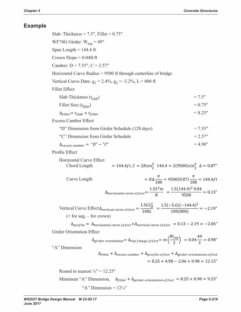
Chapter 5 Concrete Structures
WSDOT Bridge Design Manual M 23-50.17 Page 5-219 June 2017
ExampleSlab:Thickness=7.5″,Fillet=0.75″
WF74GGirder:Wtop=49″
Span Length = 144.4 ft
Crown Slope = 0.04ft/ft
Camber:D=7.55″,C=2.57″
HorizontalCurveRadius=9500ftthroughcenterlineofbridge
VerticalCurveData:g1 = 2.4%, g2 = -3.2%, L = 800 ft
FilletEffect
SlabThickness(tslab) = 7.5″
Fillet Size (tfillet) = 0.75″
5-B1.ADimWkSht3 ∆���������� ����� ������ � 1.5����
5-B1.ADimWkSht4 ∆�������� ����� ������ � 1.5����
100�
5-B1.ADimWkSht5 ∆�������� ∆���������� ����� ������ � ∆�������� ����� ������
5-B1.ADimWkSht6 ∆������ ������������ 0 forU-beamsinclined paralleltotheslab
5-B1.ADimWkSht7 ∆������ ������������ ∆��� ������ ������� � �����2 �
5-B1.ADimWkSht8 ∆������ � ∆������ ������ � ∆������� ������ � ∆������ ����������� ������
5-B1.ADimWkSht9 ∆������ � ∆������ ����������� ������
5-B1.Example1 ∆������� ����� � �������
5-B1.Example2 ∆������ ������ � ��� � ���
5-B1.Example3 � 144.4��� � � 2����∆� 144.4 � 2�9500����∆
� � � 0.87�
5-B1.Example4 � �∆ �180 � 9500�0.87� �
180 � 144.4��
5-B1.Example5 ∆���������� ����� ������� 1.5���� � 1.5�144.4�� 0.04
9500 � 0.1��
5-B1.Example6 ∆�������� ����� ������ � 1.5����
100� � 1.5��5.����144.4��100�800� � �2.19�
5-B1.Example7 ∆������� � ∆���������� ����� �������∆�������� ����� ������ � 0.1� � 2.19 � �2.0��
= 8.25″
ExcessCamberEffect
“D” Dimension from Girder Schedule (120 days) = 7.55″
“C” Dimension from Girder Schedule = 2.57″
5-B1.ADimWkSht3 ∆���������� ����� ������ � 1.5����
5-B1.ADimWkSht4 ∆�������� ����� ������ � 1.5����
100�
5-B1.ADimWkSht5 ∆�������� ∆���������� ����� ������ � ∆�������� ����� ������
5-B1.ADimWkSht6 ∆������ ������������ 0 forU-beamsinclined paralleltotheslab
5-B1.ADimWkSht7 ∆������ ������������ ∆��� ������ ������� � �����2 �
5-B1.ADimWkSht8 ∆������ � ∆������ ������ � ∆������� ������ � ∆������ ����������� ������
5-B1.ADimWkSht9 ∆������ � ∆������ ����������� ������
5-B1.Example1 ∆������� ����� � �������
5-B1.Example2 ∆������ ������ � ��� � ���
5-B1.Example3 � 144.4��� � � 2����∆� 144.4 � 2�9500����∆
� � � 0.87�
5-B1.Example4 � �∆ �180 � 9500�0.87� �
180 � 144.4��
5-B1.Example5 ∆���������� ����� ������� 1.5���� � 1.5�144.4�� 0.04
9500 � 0.1��
5-B1.Example6 ∆�������� ����� ������ � 1.5����
100� � 1.5��5.����144.4��100�800� � �2.19�
5-B1.Example7 ∆������� � ∆���������� ����� �������∆�������� ����� ������ � 0.1� � 2.19 � �2.0��
= 4.98″
ProfileEffect
HorizontalCurveEffect Chord Length
5-B1.ADimWkSht3 ∆���������� ����� ������ � 1.5����
5-B1.ADimWkSht4 ∆�������� ����� ������ � 1.5����
100�
5-B1.ADimWkSht5 ∆�������� ∆���������� ����� ������ � ∆�������� ����� ������
5-B1.ADimWkSht6 ∆������ ������������ 0 forU-beamsinclined paralleltotheslab
5-B1.ADimWkSht7 ∆������ ������������ ∆��� ������ ������� � �����2 �
5-B1.ADimWkSht8 ∆������ � ∆������ ������ � ∆������� ������ � ∆������ ����������� ������
5-B1.ADimWkSht9 ∆������ � ∆������ ����������� ������
5-B1.Example1 ∆������� ����� � �������
5-B1.Example2 ∆������ ������ � ��� � ���
5-B1.Example3 � 144.4��� � � 2����∆� 144.4 � 2�9500����∆
� � � 0.87�
5-B1.Example4 � �∆ �180 � 9500�0.87� �
180 � 144.4��
5-B1.Example5 ∆���������� ����� ������� 1.5���� � 1.5�144.4�� 0.04
9500 � 0.1��
5-B1.Example6 ∆�������� ����� ������ � 1.5����
100� � 1.5��5.����144.4��100�800� � �2.19�
5-B1.Example7 ∆������� � ∆���������� ����� �������∆�������� ����� ������ � 0.1� � 2.19 � �2.0��
Curve Length
5-B1.ADimWkSht3 ∆���������� ����� ������ � 1.5����
5-B1.ADimWkSht4 ∆�������� ����� ������ � 1.5����
100�
5-B1.ADimWkSht5 ∆�������� ∆���������� ����� ������ � ∆�������� ����� ������
5-B1.ADimWkSht6 ∆������ ������������ 0 forU-beamsinclined paralleltotheslab
5-B1.ADimWkSht7 ∆������ ������������ ∆��� ������ ������� � �����2 �
5-B1.ADimWkSht8 ∆������ � ∆������ ������ � ∆������� ������ � ∆������ ����������� ������
5-B1.ADimWkSht9 ∆������ � ∆������ ����������� ������
5-B1.Example1 ∆������� ����� � �������
5-B1.Example2 ∆������ ������ � ��� � ���
5-B1.Example3 � 144.4��� � � 2����∆� 144.4 � 2�9500����∆
� � � 0.87�
5-B1.Example4 � �∆ �180 � 9500�0.87� �
180 � 144.4��
5-B1.Example5 ∆���������� ����� ������� 1.5���� � 1.5�144.4�� 0.04
9500 � 0.1��
5-B1.Example6 ∆�������� ����� ������ � 1.5����
100� � 1.5��5.����144.4��100�800� � �2.19�
5-B1.Example7 ∆������� � ∆���������� ����� �������∆�������� ����� ������ � 0.1� � 2.19 � �2.0��
VerticalCurveEffect
5-B1.ADimWkSht3 ∆���������� ����� ������ � 1.5����
5-B1.ADimWkSht4 ∆�������� ����� ������ � 1.5����
100�
5-B1.ADimWkSht5 ∆�������� ∆���������� ����� ������ � ∆�������� ����� ������
5-B1.ADimWkSht6 ∆������ ������������ 0 forU-beamsinclined paralleltotheslab
5-B1.ADimWkSht7 ∆������ ������������ ∆��� ������ ������� � �����2 �
5-B1.ADimWkSht8 ∆������ � ∆������ ������ � ∆������� ������ � ∆������ ����������� ������
5-B1.ADimWkSht9 ∆������ � ∆������ ����������� ������
5-B1.Example1 ∆������� ����� � �������
5-B1.Example2 ∆������ ������ � ��� � ���
5-B1.Example3 � 144.4��� � � 2����∆� 144.4 � 2�9500����∆
� � � 0.87�
5-B1.Example4 � �∆ �180 � 9500�0.87� �
180 � 144.4��
5-B1.Example5 ∆���������� ����� ������� 1.5���� � 1.5�144.4�� 0.04
9500 � 0.1��
5-B1.Example6 ∆�������� ����� ������ � 1.5����
100� � 1.5��5.����144.4��100�800� � �2.19�
5-B1.Example7 ∆������� � ∆���������� ����� �������∆�������� ����� ������ � 0.1� � 2.19 � �2.0��
(+ for sag, – for crown)
5-B1.ADimWkSht3 ∆���������� ����� ������ � 1.5����
5-B1.ADimWkSht4 ∆�������� ����� ������ � 1.5����
100�
5-B1.ADimWkSht5 ∆�������� ∆���������� ����� ������ � ∆�������� ����� ������
5-B1.ADimWkSht6 ∆������ ������������ 0 forU-beamsinclined paralleltotheslab
5-B1.ADimWkSht7 ∆������ ������������ ∆��� ������ ������� � �����2 �
5-B1.ADimWkSht8 ∆������ � ∆������ ������ � ∆������� ������ � ∆������ ����������� ������
5-B1.ADimWkSht9 ∆������ � ∆������ ����������� ������
5-B1.Example1 ∆������� ����� � �������
5-B1.Example2 ∆������ ������ � ��� � ���
5-B1.Example3 � 144.4��� � � 2����∆� 144.4 � 2�9500����∆
� � � 0.87�
5-B1.Example4 � �∆ �180 � 9500�0.87� �
180 � 144.4��
5-B1.Example5 ∆���������� ����� ������� 1.5���� � 1.5�144.4�� 0.04
9500 � 0.1��
5-B1.Example6 ∆�������� ����� ������ � 1.5����
100� � 1.5��5.����144.4��100�800� � �2.19�
5-B1.Example7 ∆������� � ∆���������� ����� �������∆�������� ����� ������ � 0.1� � 2.19 � �2.0��GirderOrientationEffect
5-B1.Example8 ∆������ ������������ ∆��� ������ ������� � �����2 � � ���4 49
2 � ��9��
5-B1.Example9 ∆������ � ∆������ ������ � ∆������� ������ � ∆������ ����������� ������ � ��2� � 4�9� � 2��� � ��9� � �2����
5-B1.Example10 ∆������ � ∆������ ����������� ������ � ��2� � ��9� � 9�2��
“A” Dimension
5-B1.Example8 ∆������ ������������ ∆��� ������ ������� � �����2 � � ���4 49
2 � ��9��
5-B1.Example9 ∆������ � ∆������ ������ � ∆������� ������ � ∆������ ����������� ������ � ��2� � 4�9� � 2��� � ��9� � �2����
5-B1.Example10 ∆������ � ∆������ ����������� ������ � ��2� � ��9� � 9�2��
5-B1.Example8 ∆������ ������������ ∆��� ������ ������� � �����2 � � ���4 49
2 � ��9��
5-B1.Example9 ∆������ � ∆������ ������ � ∆������� ������ � ∆������ ����������� ������ � ��2� � 4�9� � 2��� � ��9� � �2����
5-B1.Example10 ∆������ � ∆������ ����������� ������ � ��2� � ��9� � 9�2��
Roundtonearest¼″=12.25″
Minimum “A” Dimension,
5-B1.Example8 ∆������ ������������ ∆��� ������ ������� � �����2 � � ���4 49
2 � ��9��
5-B1.Example9 ∆������ � ∆������ ������ � ∆������� ������ � ∆������ ����������� ������ � ��2� � 4�9� � 2��� � ��9� � �2����
5-B1.Example10 ∆������ � ∆������ ����������� ������ � ��2� � ��9� � 9�2��
“A”Dimension=12¼″

Page 5-220 WSDOT Bridge Design Manual M 23-50.17 June 2017
Appendix 5-B2 Vacant
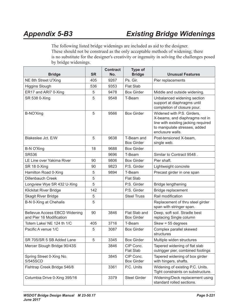
WSDOT Bridge Design Manual M 23-50.17 Page 5-221 June 2017
Appendix 5-B3 Existing Bridge Widenings
Thefollowinglistedbridgewideningsareincludedasaidtothedesigner.Theseshouldnotbeconstruedastheonlyacceptablemethodsofwidening;thereisnosubstituteforthedesigner'screativityoringenuityinsolvingthechallengesposedbybridgewidenings.
Bridge SRContract
No. Type of Bridge Unusual Features
NE 8th Street U'Xing 405 9267 Ps . Gir . Pier replacementsHiggins Slough 536 9353 Flat SlabER17 and ARI7 0-Xing 5 9478 Box Girder Middle and outside widening .SR 538 0-Xing 5 9548 T-Beam Unbalanced widening section
support at diaphragms until completion of closure pour .
B-NO'Xing 5 9566 Box Girder Widened with P .S . Girders, X-beams, and diaphragms not in line with existing jacking required to manipulate stresses, added enclusure walls .
Blakeslee Jct . E/W 5 9638 T-Beam and Box Girder
Post-tensioned X-beam, single web.
B-N O'Xing 18 9688 Box GirderSR536 9696 T-Beam Similar to Contract 9548 .LE Line over Yakima River 90 9806 Box Girder Pier shaft .SR 18 0-Xing 90 9823 P .S . Girder Lightweight concreteHamilton Road 0-Xing 5 9894 T-Beam Precast girder in one spanDillenbauch Creek 5 Flat SlabLongview Wye SR 432 U-Xing 5 P .S . Girder Bridge lengtheningKlickitat River Bridge 142 P .S . Girder Bridge replacementSkagit River Bridge 5 Steel Truss Rail modificationB-N 0-Xing at Chehalis 5 Replacement of thru steel girder
span with stringer span .Bellevue Access EBCD Widening and Pier 16 Modification
90 3846 Flat Slab and Box Girder
Deep, soft soil. Stradle best replacing Single column
Totem Lake/ NE 124 th 1/C 405 3716 T-Beam Skew = 55 degreesPacific A venue 1/C 5 3087 Box Girder Complex parallel skewed
structuresSR 705/SR 5 SB Added Lane 5 3345 Box Girder Multiple widen structuresMercer Slough Bridge 90/43S 3846 CIP Conc .
Flat SlabTapered widening of flat slab outrigger pier, combined footings
Spring Street 0-Xing No . 5/545SCD
3845 CIP Conc . Box Girder
Tapered widening of box girder with hingers, shafts .
Fishtrap Creek Bridge 546/8 3361 P .C . Units Widening of existing P .C . Units . Tight constraints on substructure.
Columbia Drive 0-Xing 395/16 3379 Steel Girder Widening/Deck replacement using standard rolled sections .

Concrete Structures Chapter 5
Page 5-222 WSDOT Bridge Design Manual M 23-50.17 June 2017
Bridge SRContract
No. Type of Bridge Unusual Features
S 74th-72nd St . 0-Xing No . 5/426 3207 CIP Haunched Con . Box Girder
Haunched P.C. P.T. Bath Tub girder sections .
Pacific Avenue 0-Xing No. 5/332 3087 CIP Cone . Box Girder
Longitudinal joint between new and existing .
Tye River Bridges 2/126 and 2/127
3565 CIP Cone . Tee Beam
Stage construction with crown shift .
SR 20 and BNRR 0-Xing No . 5/714
9220 CIP Cone . Tee Beam
Widened with prestressed girders raised crossbeam.
NE 8th St . U'Xing No . 405/43 9267 Prestressed Girders
Pier replacement - widening .
So . 212th St . U'Xing SR 167 3967 Prestressed Girders
Widening constructed as stand alone structure . Widening column designed as strong column for retrofit.
SE 232nd St . SR 18 5801 CIPConc . Post-tensioned Box
Skew = 50 degree . Longitudinal "link pin" deck joint between new and existing to accommodate new creep .
Obdashian Bridge 2/275 N/A 1999
CIP Post-tensioned Box
Sidewalk widening with pipe struts .
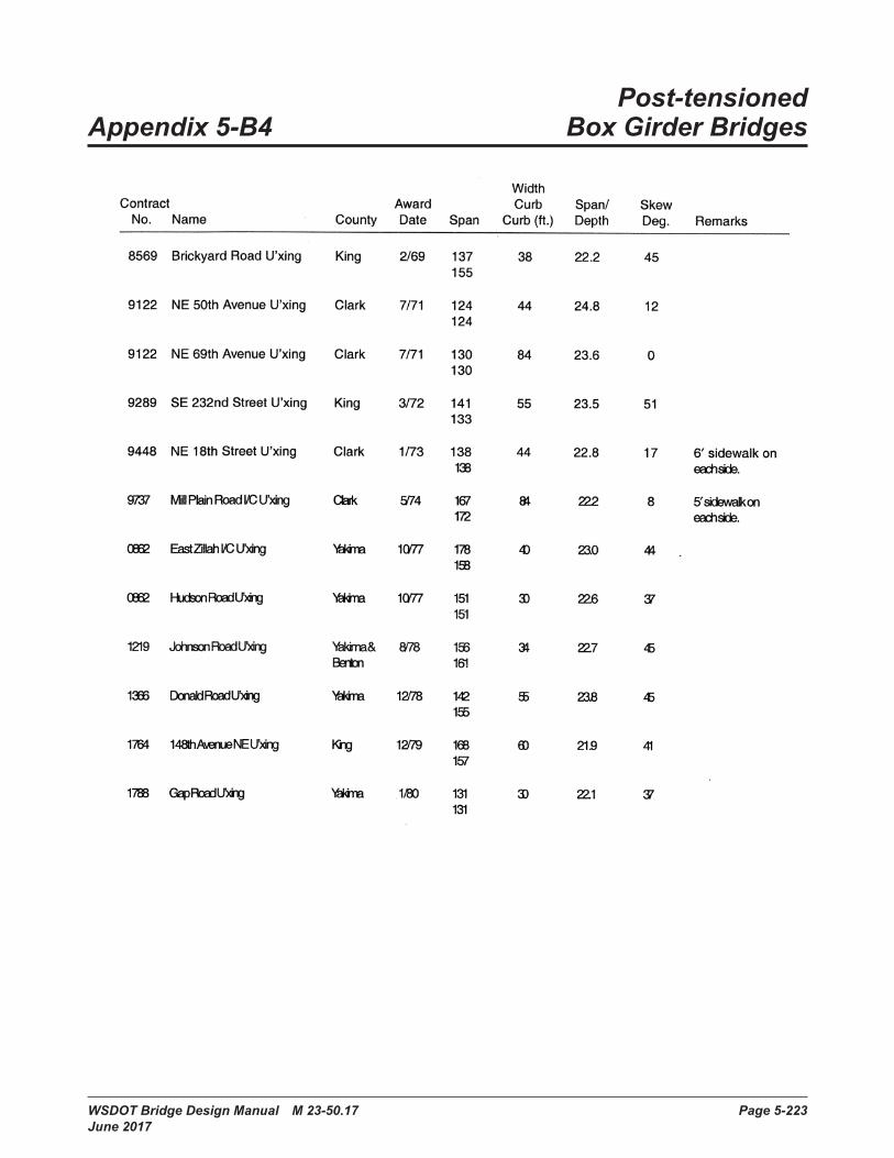
WSDOT Bridge Design Manual M 23-50.17 Page 5-223 June 2017
Post-tensioned Appendix 5-B4 Box Girder Bridges

Concrete Structures Chapter 5
Page 5-224 WSDOT Bridge Design Manual M 23-50.17 June 2017

Chapter 5 Concrete Structures
WSDOT Bridge Design Manual M 23-50.17 Page 5-225 June 2017

Concrete Structures Chapter 5
Page 5-226 WSDOT Bridge Design Manual M 23-50.17 June 2017
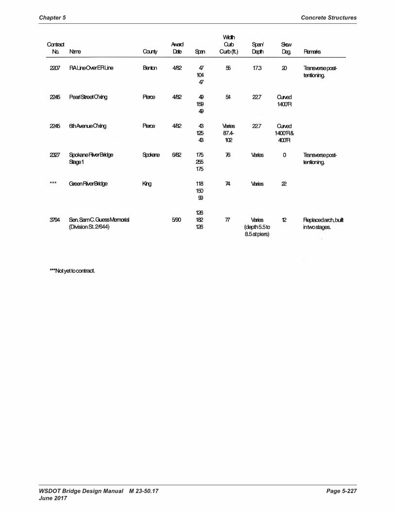
Chapter 5 Concrete Structures
WSDOT Bridge Design Manual M 23-50.17 Page 5-227 June 2017

Concrete Structures Chapter 5
Page 5-228 WSDOT Bridge Design Manual M 23-50.17 June 2017

WSDOT Bridge Design Manual M 23-50.17 Page 5-229 June 2017
Simple Span Appendix 5-B5 Prestressed Girder DesignAppendix 5-B5 Simple Span
Prestressed Girder DesignReferences
Unit Definitions and Mathcad System Constantskcf kip ft
3÷:= ORIGIN 1:=
Design Outline
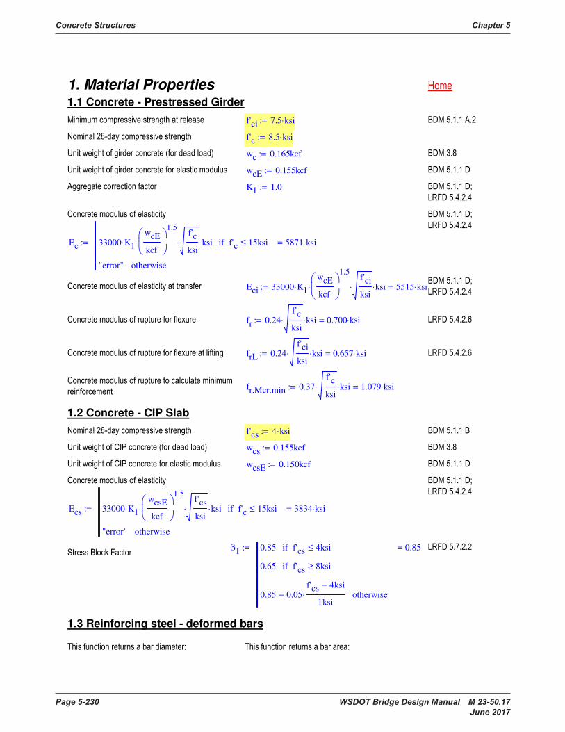
Concrete Structures Chapter 5
Page 5-230 WSDOT Bridge Design Manual M 23-50.17 June 2017
1. Material Properties 1.1 Concrete - Prestressed Girder
f'ci 7.5 ksi⋅:=
f'c 8.5 ksi⋅:=
wc 0.165kcf:=
wcE 0.155kcf:=
K1 1.0:=
Ec 33000 K1⋅
wcE
kcf
1.5
⋅
f'c
ksi⋅ ksi⋅ f'c 15ksi≤if
"error" otherwise
5871 ksi⋅=:=
Eci 33000 K1⋅
wcE
kcf
1.5
⋅
f'ci
ksi⋅ ksi⋅ 5515 ksi⋅=:=
fr 0.24f'c
ksi⋅ ksi⋅ 0.700 ksi⋅=:=
frL 0.24f'ci
ksi⋅ ksi⋅ 0.657 ksi⋅=:=
fr.Mcr.min 0.37
f'c
ksi⋅ ksi⋅ 1.079 ksi⋅=:=
1.2 Concrete - CIP Slab
f'cs 4 ksi⋅:=
wcs 0.155kcf:=
wcsE 0.150kcf:=
Ecs 33000 K1⋅
wcsE
kcf
1.5
⋅
f'cs
ksi⋅ ksi⋅ f'c 15ksi≤if
"error" otherwise
3834 ksi⋅=:=
β1 0.85 f'cs 4ksi≤if
0.65 f'cs 8ksi≥if
0.85 0.05f'cs 4ksi−
1ksi⋅− otherwise
0.85=:=
1.3 Reinforcing steel - deformed bars
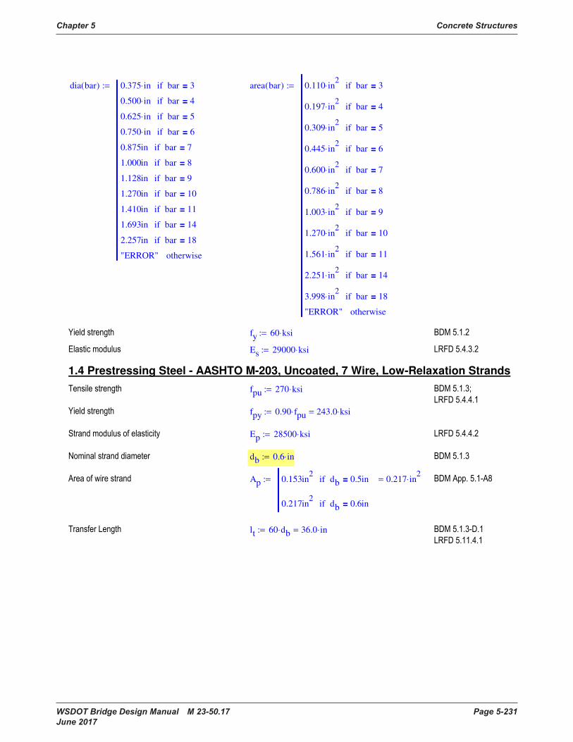
Chapter 5 Concrete Structures
WSDOT Bridge Design Manual M 23-50.17 Page 5-231 June 2017
dia bar( ) 0.375 in⋅ bar 3=if
0.500 in⋅ bar 4=if
0.625 in⋅ bar 5=if
0.750 in⋅ bar 6=if
0.875in bar 7=if
1.000in bar 8=if
1.128in bar 9=if
1.270in bar 10=if
1.410in bar 11=if
1.693in bar 14=if
2.257in bar 18=if
"ERROR" otherwise
:= area bar( ) 0.110 in2
⋅ bar 3=if
0.197 in2
⋅ bar 4=if
0.309 in2
⋅ bar 5=if
0.445 in2
⋅ bar 6=if
0.600 in2
⋅ bar 7=if
0.786 in2
⋅ bar 8=if
1.003 in2
⋅ bar 9=if
1.270 in2
⋅ bar 10=if
1.561 in2
⋅ bar 11=if
2.251 in2
⋅ bar 14=if
3.998 in2
⋅ bar 18=if
"ERROR" otherwise
:=
fy 60 ksi⋅:=
Es 29000 ksi⋅:=
1.4 Prestressing Steel - AASHTO M-203, Uncoated, 7 Wire, Low-Relaxation Strands
fpu 270 ksi⋅:=
fpy 0.90 fpu⋅ 243.0 ksi⋅=:=
Ep 28500 ksi⋅:=
db 0.6 in⋅:=
Ap 0.153in2
db 0.5in=if
0.217in2
db 0.6in=if
0.217 in2
⋅=:=
lt 60 db⋅ 36.0 in⋅=:=
1. Material Properties 1.1 Concrete - Prestressed Girder
f'ci 7.5 ksi⋅:=
f'c 8.5 ksi⋅:=
wc 0.165kcf:=
wcE 0.155kcf:=
K1 1.0:=
Ec 33000 K1⋅
wcE
kcf
1.5
⋅
f'c
ksi⋅ ksi⋅ f'c 15ksi≤if
"error" otherwise
5871 ksi⋅=:=
Eci 33000 K1⋅
wcE
kcf
1.5
⋅
f'ci
ksi⋅ ksi⋅ 5515 ksi⋅=:=
fr 0.24f'c
ksi⋅ ksi⋅ 0.700 ksi⋅=:=
frL 0.24f'ci
ksi⋅ ksi⋅ 0.657 ksi⋅=:=
fr.Mcr.min 0.37
f'c
ksi⋅ ksi⋅ 1.079 ksi⋅=:=
1.2 Concrete - CIP Slab
f'cs 4 ksi⋅:=
wcs 0.155kcf:=
wcsE 0.150kcf:=
Ecs 33000 K1⋅
wcsE
kcf
1.5
⋅
f'cs
ksi⋅ ksi⋅ f'c 15ksi≤if
"error" otherwise
3834 ksi⋅=:=
β1 0.85 f'cs 4ksi≤if
0.65 f'cs 8ksi≥if
0.85 0.05f'cs 4ksi−
1ksi⋅− otherwise
0.85=:=
1.3 Reinforcing steel - deformed bars
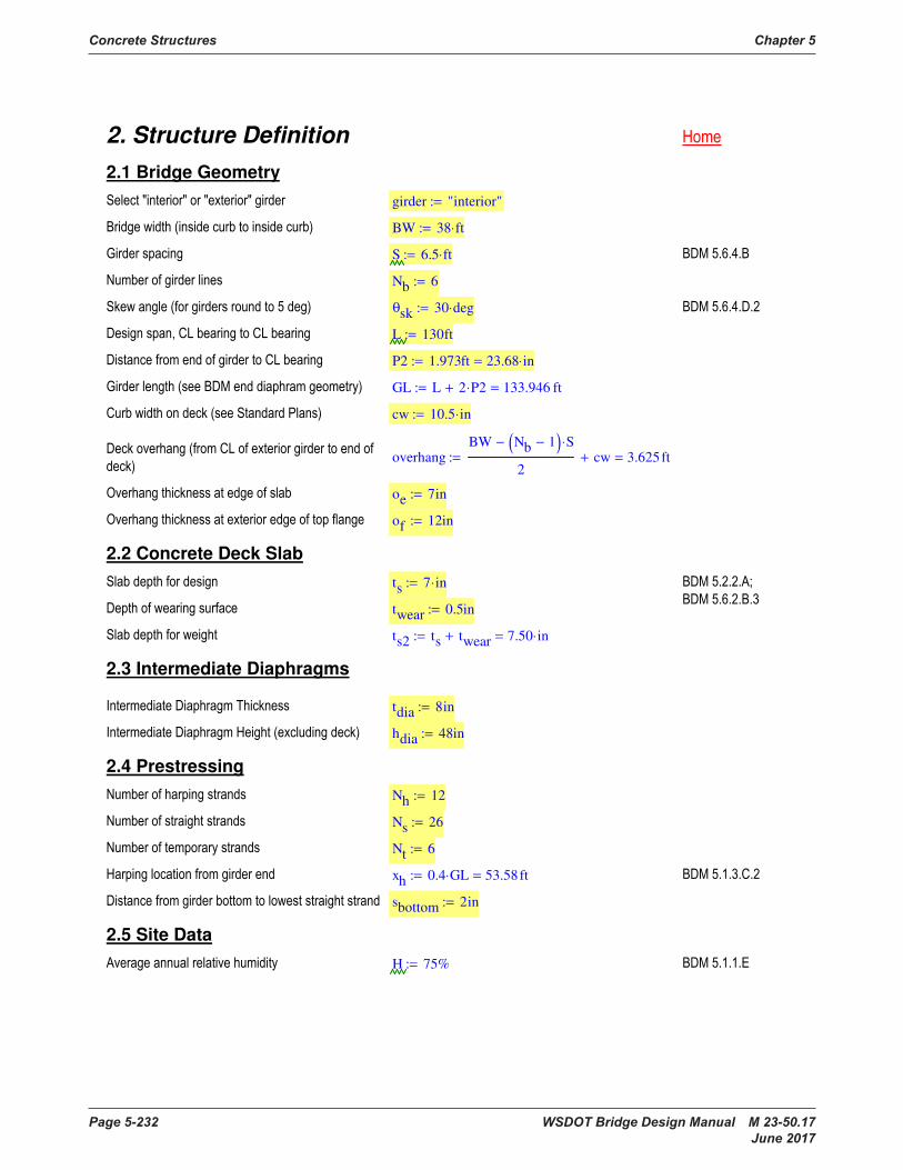
Concrete Structures Chapter 5
Page 5-232 WSDOT Bridge Design Manual M 23-50.17 June 2017
2. Structure Definition
2.1 Bridge Geometry
girder "interior":=
BW 38 ft⋅:=
S 6.5 ft⋅:=
Nb 6:=
θsk 30 deg⋅:=
L 130ft:=
P2 1.973ft 23.68 in⋅=:=
GL L 2 P2⋅+ 133.946 ft=:=
cw 10.5 in⋅:=
overhang
BW Nb 1−( ) S⋅−
2cw+ 3.625ft=:=
oe 7in:=
of 12in:=
2.2 Concrete Deck Slab
ts 7 in⋅:= twear 0.5in:=
ts2 ts twear+ 7.50 in⋅=:=
2.3 Intermediate Diaphragms
tdia 8in:=
hdia 48in:=
2.4 Prestressing
Nh 12:=
Ns 26:=
Nt 6:=
xh 0.4 GL⋅ 53.58ft=:=
sbottom 2in:=
2.5 Site Data
H 75%:=

Chapter 5 Concrete Structures
WSDOT Bridge Design Manual M 23-50.17 Page 5-233 June 2017
3. Computation of Section Properties
3.1 Girder Properties
girdertype "WF74G":=
row match girdertype BDMTable5.6.1, ( )1( )1
12.0=:=
dg BDMTable5.6.1row 2,
in 74.0 in⋅=:=
Ag BDMTable5.6.1row 3,
in2
923.5 in2
⋅=:=
Ig BDMTable5.6.1row 4,
in4
734356 in4
⋅=:=
Ybg BDMTable5.6.1row 5,
in 35.660 in⋅=:=
VSr BDMTable5.6.1row 7,
in 3.190 in⋅=:=
wg Ag wc⋅ 1.058kip
ft⋅=:=
bw 6.125in:=
bf 49in:=
bf.bot 38.375in:=
Iy 72018.4in4
:=
L1 5ft:=
LL 10ft:=
LT 10ft:=
Ytg dg Ybg− 38.340 in⋅=:=
Stg Ig Ytg÷ 19153.8 in3
⋅=:=
Sbg Ig Ybg÷ 20593.3 in3
⋅=:=
2. Structure Definition
2.1 Bridge Geometry
girder "interior":=
BW 38 ft⋅:=
S 6.5 ft⋅:=
Nb 6:=
θsk 30 deg⋅:=
L 130ft:=
P2 1.973ft 23.68 in⋅=:=
GL L 2 P2⋅+ 133.946 ft=:=
cw 10.5 in⋅:=
overhang
BW Nb 1−( ) S⋅−
2cw+ 3.625ft=:=
oe 7in:=
of 12in:=
2.2 Concrete Deck Slab
ts 7 in⋅:= twear 0.5in:=
ts2 ts twear+ 7.50 in⋅=:=
2.3 Intermediate Diaphragms
tdia 8in:=
hdia 48in:=
2.4 Prestressing
Nh 12:=
Ns 26:=
Nt 6:=
xh 0.4 GL⋅ 53.58ft=:=
sbottom 2in:=
2.5 Site Data
H 75%:=

Concrete Structures Chapter 5
Page 5-234 WSDOT Bridge Design Manual M 23-50.17 June 2017
dest 0.72 dg ts+( )⋅ 4.86 ft⋅=:=
barv 5:=
VR1 1,
1.5in:= VR11 1,
VR1 1,
:=
VR1 2,
VR1 1,
:= VR11 2,
VR1 2,
:=
VR2 1,
20in:= VR10 1,
VR2 1,
:=
VR2 2,
2.5in:= VR10 2,
VR2 2,
:=
VR3 1,
72in:= VR9 1,
VR3 1,
:=
VR3 2,
6in:= VR9 2,
VR3 2,
:=
VR4 1,
120in:= VR8 1,
VR4 1,
:=
VR4 2,
12in:= VR8 2,
VR4 2,
:=
VR5 1,
120in:= VR7 1,
VR5 1,
:=
VR5 2,
12in:= VR7 2,
VR5 2,
:=
VR6 1,
GL
1
5
i
VRi 1,
=
−
7
11
i
VRi 1,
=
−:=
VR6 2,
18in:=
VR
in⋅=

Chapter 5 Concrete Structures
WSDOT Bridge Design Manual M 23-50.17 Page 5-235 June 2017
chk3 1,
if
1
rows VR( )
i
VRi 1,
=
GL= "OK", "NG",
"OK"=:=
3.2 "A" Dimension
Afi 0.75in:=
AEx 2.5in:=
Super 0.02:=
SH 0ft:=
RH 0ft:=
LVC 1000ft:=
g1 0:=
g2 0−:=
AHC
1.5 SH ft÷( )2
⋅ Super⋅
RH ft÷
in⋅ 0.000 in⋅=:=
AVC
1.5 g2 g1−( )⋅GL
ft
2
⋅
100LVC
ft⋅
in⋅ 0.000 in⋅=:=
AOrient Superbf
2⋅ 0.490 in⋅=:=
AP1 Ceil ts2 Afi+ AEx+ AHC+ AVC+ AOrient+1
4in,
11.25 in⋅=:=
A max AP1 ts2 Afi+, ( ) 11.25 in⋅=:=
3.3 Span-to-Depth Ratio (Optional Criteria)
depthmin 0.045 L⋅ 70.2 in⋅=:=
dest 0.72 dg ts+( )⋅ 4.86 ft⋅=:=
barv 5:=
VR1 1,
1.5in:= VR11 1,
VR1 1,
:=
VR1 2,
VR1 1,
:= VR11 2,
VR1 2,
:=
VR2 1,
20in:= VR10 1,
VR2 1,
:=
VR2 2,
2.5in:= VR10 2,
VR2 2,
:=
VR3 1,
72in:= VR9 1,
VR3 1,
:=
VR3 2,
6in:= VR9 2,
VR3 2,
:=
VR4 1,
120in:= VR8 1,
VR4 1,
:=
VR4 2,
12in:= VR8 2,
VR4 2,
:=
VR5 1,
120in:= VR7 1,
VR5 1,
:=
VR5 2,
12in:= VR7 2,
VR5 2,
:=
VR6 1,
GL
1
5
i
VRi 1,
=
−
7
11
i
VRi 1,
=
−:=
VR6 2,
18in:=
VR
in⋅=

Concrete Structures Chapter 5
Page 5-236 WSDOT Bridge Design Manual M 23-50.17 June 2017
chk3 2,
if depthmin dg ts+≤ "OK", "NG", ( ) "OK"=:=
3.4 Composite Section Properties
chk3 3,
if θsk 75deg> "NG", "OK", ( ) "OK"=:=
bi S 78.00 in⋅=:=
bex 0.5 S⋅ overhang+ 82.50 in⋅=:=
be bi girder "interior"=if
bex girder "exterior"=if
78.00 in⋅=:=
n
Ecs
Ec
0.65=:=
be.trans be n⋅ 50.94 in⋅=:=
Islab be.trans ts3
⋅ 12÷ 1456.0 in4
⋅=:=
Aslab be.trans ts⋅ 356.6 in2
⋅=:=
Ybs dg 0.5 ts⋅+ 77.5 in⋅=:=
Yb
Aslab Ybs⋅ Ag Ybg⋅+
Aslab Ag+
47.31 in⋅=:=
Yt dg Yb− 26.69 in⋅=:=
Yts ts Yt+ 33.69 in⋅=:=
Islabc Aslab Yts 0.5ts−( )2
⋅ Islab+ 326347 in4
⋅=:=
Igc Ag Yb Ybg−( )2
⋅ Ig+ 859801 in4
⋅=:=
Ic Islabc Igc+ 1186148 in4
⋅=:=
Sb Ic Yb÷ 25069 in3
⋅=:=
St Ic Yt÷ 44450 in3
⋅=:=
Sts
Ic
Yts
1
n
53919 in3
⋅=:=
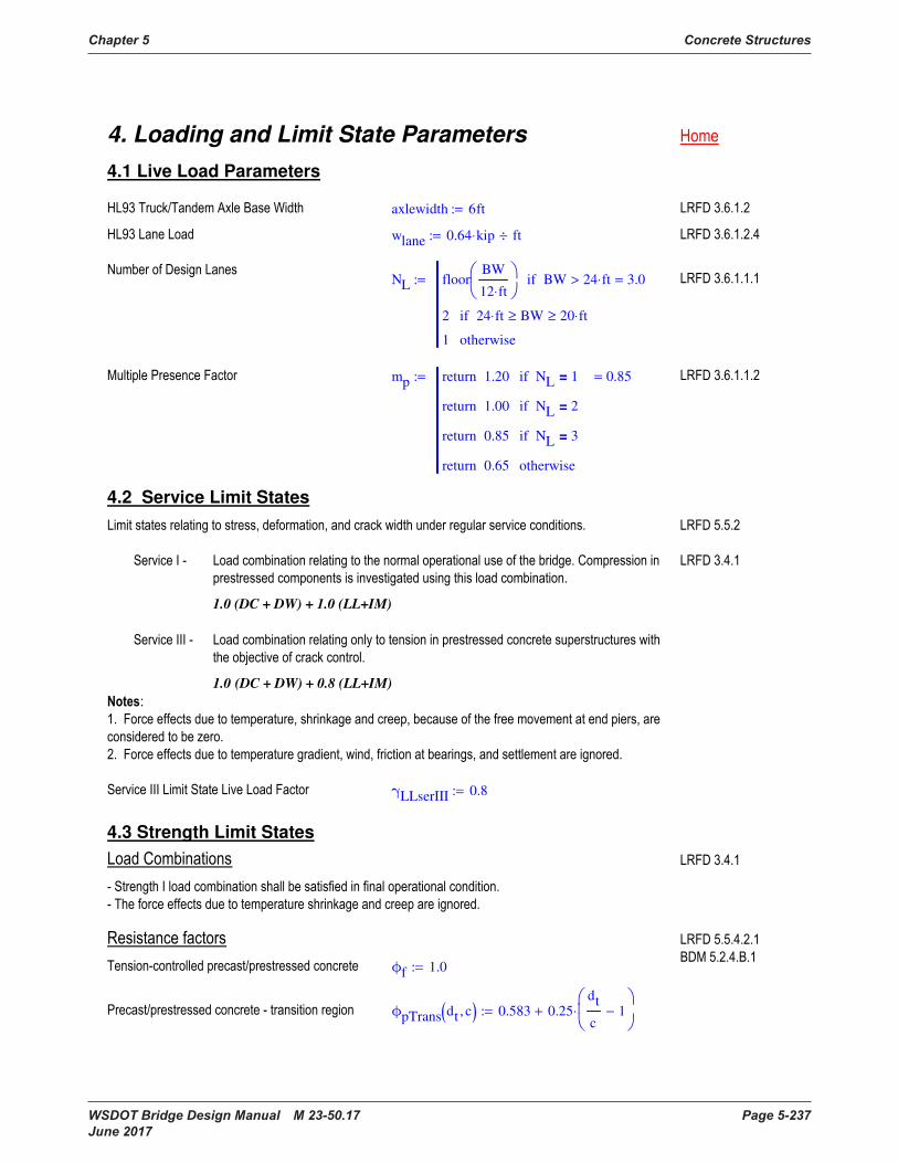
Chapter 5 Concrete Structures
WSDOT Bridge Design Manual M 23-50.17 Page 5-237 June 2017
4. Loading and Limit State Parameters
4.1 Live Load Parameters
axlewidth 6ft:=
wlane 0.64 kip⋅ ft÷:=
NL floor
BW
12 ft⋅
BW 24 ft⋅>if
2 24 ft⋅ BW≥ 20 ft⋅≥if
1 otherwise
3.0=:=
mp 1.20return NL 1=if
1.00return NL 2=if
0.85return NL 3=if
0.65return otherwise
0.85=:=
4.2 Service Limit States
1.0 (DC + DW) + 1.0 (LL+IM)
1.0 (DC + DW) + 0.8 (LL+IM)
γLLserIII 0.8:=
4.3 Strength Limit States
ϕf 1.0:=
ϕpTrans dt c, ( ) 0.583 0.25dt
c1−
⋅+:=
chk3 2,
if depthmin dg ts+≤ "OK", "NG", ( ) "OK"=:=
3.4 Composite Section Properties
chk3 3,
if θsk 75deg> "NG", "OK", ( ) "OK"=:=
bi S 78.00 in⋅=:=
bex 0.5 S⋅ overhang+ 82.50 in⋅=:=
be bi girder "interior"=if
bex girder "exterior"=if
78.00 in⋅=:=
n
Ecs
Ec
0.65=:=
be.trans be n⋅ 50.94 in⋅=:=
Islab be.trans ts3
⋅ 12÷ 1456.0 in4
⋅=:=
Aslab be.trans ts⋅ 356.6 in2
⋅=:=
Ybs dg 0.5 ts⋅+ 77.5 in⋅=:=
Yb
Aslab Ybs⋅ Ag Ybg⋅+
Aslab Ag+
47.31 in⋅=:=
Yt dg Yb− 26.69 in⋅=:=
Yts ts Yt+ 33.69 in⋅=:=
Islabc Aslab Yts 0.5ts−( )2
⋅ Islab+ 326347 in4
⋅=:=
Igc Ag Yb Ybg−( )2
⋅ Ig+ 859801 in4
⋅=:=
Ic Islabc Igc+ 1186148 in4
⋅=:=
Sb Ic Yb÷ 25069 in3
⋅=:=
St Ic Yt÷ 44450 in3
⋅=:=
Sts
Ic
Yts
1
n
53919 in3
⋅=:=
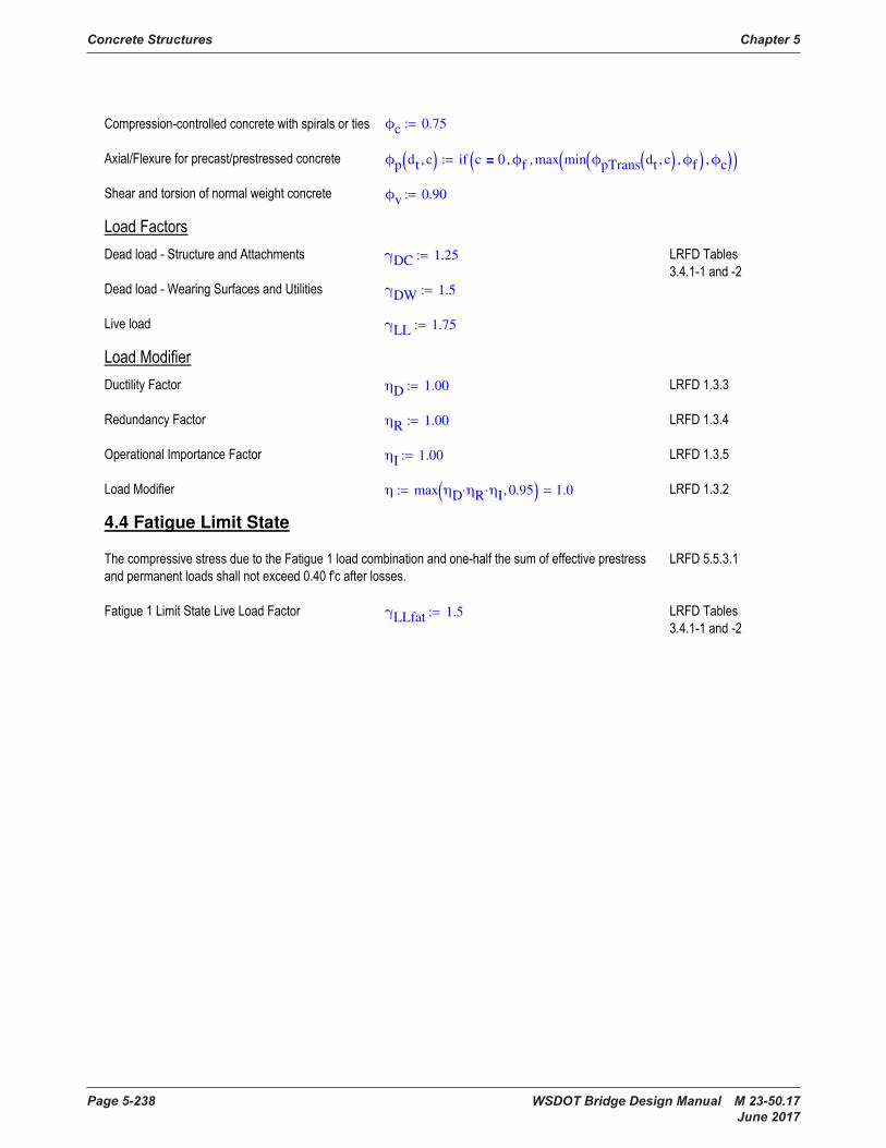
Concrete Structures Chapter 5
Page 5-238 WSDOT Bridge Design Manual M 23-50.17 June 2017
ϕc 0.75:=
ϕp dt c, ( ) if c 0= ϕf, max min ϕpTrans dt c, ( ) ϕf, ( ) ϕc, ( ), ( ):=
ϕv 0.90:=
γDC 1.25:=
γDW 1.5:=
γLL 1.75:=
ηD 1.00:=
ηR 1.00:=
ηI 1.00:=
η max ηD ηR⋅ ηI⋅ 0.95, ( ) 1.0=:=
4.4 Fatigue Limit State
γLLfat 1.5:=
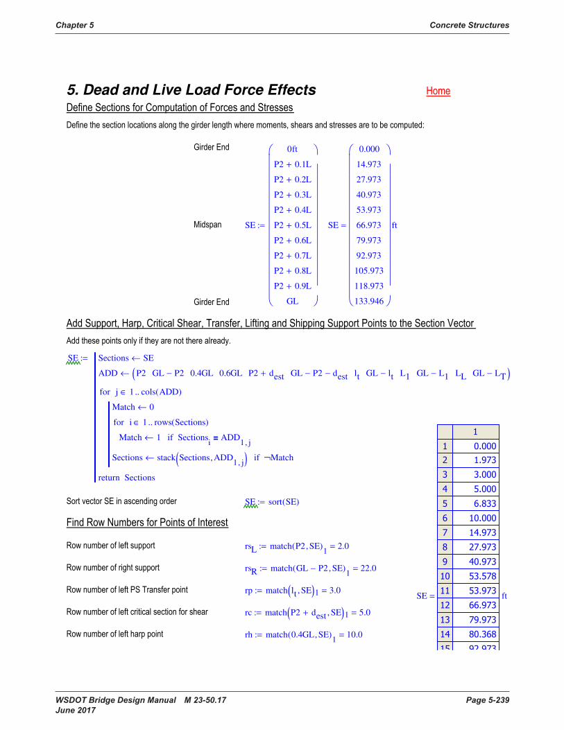
Chapter 5 Concrete Structures
WSDOT Bridge Design Manual M 23-50.17 Page 5-239 June 2017
5. Dead and Live Load Force Effects
SE
0ft
P2 0.1L+
P2 0.2L+
P2 0.3L+
P2 0.4L+
P2 0.5L+
P2 0.6L+
P2 0.7L+
P2 0.8L+
P2 0.9L+
GL
:= SE
0.000
14.973
27.973
40.973
53.973
66.973
79.973
92.973
105.973
118.973
133.946
ft=
SE Sections SE←
ADD P2 GL P2− 0.4GL 0.6GL P2 dest+ GL P2− dest− lt GL lt− L1 GL L1− LL GL LT−( )←
Match 0←
Match 1← Sectionsi
ADD1 j,
=if
i 1 rows Sections( )..∈for
Sections stack Sections ADD1 j,
, ( )← Match¬if
j 1 cols ADD( )..∈for
Sectionsreturn
:=
SE sort SE( ):=
rsL match P2 SE, ( )1
2.0=:=
rsR match GL P2− SE, ( )1
22.0=:=
rp match lt SE, ( )1 3.0=:=SE
ft=
rc match P2 dest+ SE, ( )1 5.0=:=
rh match 0.4GL SE, ( )1
10.0=:=
ϕc 0.75:=
ϕp dt c, ( ) if c 0= ϕf, max min ϕpTrans dt c, ( ) ϕf, ( ) ϕc, ( ), ( ):=
ϕv 0.90:=
γDC 1.25:=
γDW 1.5:=
γLL 1.75:=
ηD 1.00:=
ηR 1.00:=
ηI 1.00:=
η max ηD ηR⋅ ηI⋅ 0.95, ( ) 1.0=:=
4.4 Fatigue Limit State
γLLfat 1.5:=

Concrete Structures Chapter 5
Page 5-240 WSDOT Bridge Design Manual M 23-50.17 June 2017
rm match P2 0.5L+ SE, ( )1
12.0=:=
rl1 match L1 SE, ( )1 4.0=:=
rl2 match GL L1− SE, ( )1 20.0=:=
rbL match LL SE, ( )1 6.0=:=
rbR match GL LT− SE, ( )1 18.0=:=
i 1 rows SE( )..:=
Muniform w L, x, ( ) 0kip ft⋅return x 0ft< x L>∨if
w x⋅
2L x−( )⋅
:=
Vuniform w L, x, ( ) 0kipreturn x 0ft< x L>∨if
wL
2x−
⋅
:=
Mpoint P a, L, x, ( ) 0kip ft⋅return x 0ft< x L>∨if
0kip ft⋅return a 0ft< a L>∨if
P L x−( )⋅ a⋅
L0ft a≤ x≤if
P L a−( )⋅ x⋅
Lx a< L≤if
:=
Vpoint P a, L, x, ( ) 0kipreturn x 0ft< x L>∨if
0kip ft⋅return a 0ft< a L>∨if
P a⋅
L− 0ft a≤ x<if
P L a−( )⋅
Lx a≤ L≤if
:=
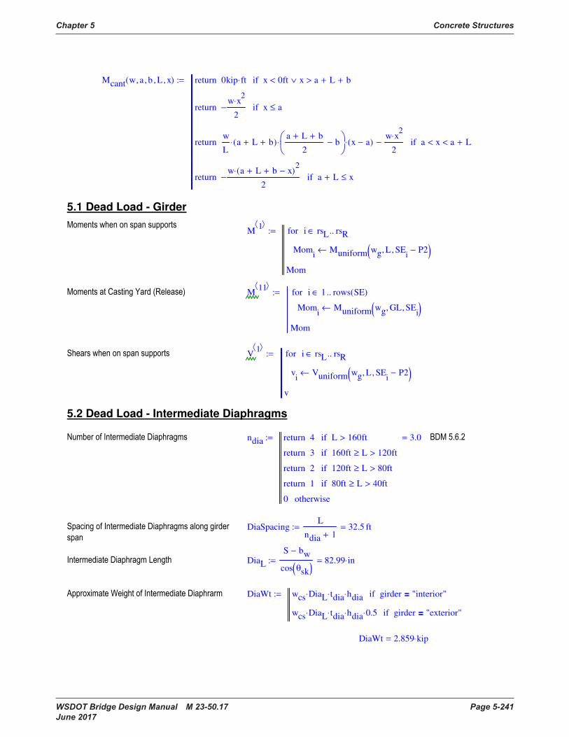
Chapter 5 Concrete Structures
WSDOT Bridge Design Manual M 23-50.17 Page 5-241 June 2017
Mcant w a, b, L, x, ( ) 0kip ft⋅return x 0ft< x a L+ b+>∨if
w x2
⋅
2−return x a≤if
w
La L+ b+( )⋅
a L+ b+
2b−
⋅ x a−( )⋅w x
2⋅
2−return a x< a L+<if
w a L+ b+ x−( )2
⋅
2−return a L+ x≤if
:=
5.1 Dead Load - Girder
M
1
Momi
Muniform wg L, SEi
P2−, ( )←
i rsL rsR..∈for
Mom
:=
M11
Momi
Muniform wg GL, SEi
, ( )←
i 1 rows SE( )..∈for
Mom
:=
V1
vi
Vuniform wg L, SEi
P2−, ( )←
i rsL rsR..∈for
v
:=
5.2 Dead Load - Intermediate Diaphragms
ndia 4return L 160ft>if
3return 160ft L≥ 120ft>if
2return 120ft L≥ 80ft>if
1return 80ft L≥ 40ft>if
0 otherwise
3.0=:=
DiaSpacingL
ndia 1+
32.5 ft=:=
DiaL
S bw−
cos θsk( )82.99 in⋅=:=
DiaWt wcs DiaL⋅ tdia⋅ hdia⋅ girder "interior"=if
wcs DiaL⋅ tdia⋅ hdia⋅ 0.5⋅ girder "exterior"=if
:=
DiaWt 2.859 kip⋅=
rm match P2 0.5L+ SE, ( )1
12.0=:=
rl1 match L1 SE, ( )1 4.0=:=
rl2 match GL L1− SE, ( )1 20.0=:=
rbL match LL SE, ( )1 6.0=:=
rbR match GL LT− SE, ( )1 18.0=:=
i 1 rows SE( )..:=
Muniform w L, x, ( ) 0kip ft⋅return x 0ft< x L>∨if
w x⋅
2L x−( )⋅
:=
Vuniform w L, x, ( ) 0kipreturn x 0ft< x L>∨if
wL
2x−
⋅
:=
Mpoint P a, L, x, ( ) 0kip ft⋅return x 0ft< x L>∨if
0kip ft⋅return a 0ft< a L>∨if
P L x−( )⋅ a⋅
L0ft a≤ x≤if
P L a−( )⋅ x⋅
Lx a< L≤if
:=
Vpoint P a, L, x, ( ) 0kipreturn x 0ft< x L>∨if
0kip ft⋅return a 0ft< a L>∨if
P a⋅
L− 0ft a≤ x<if
P L a−( )⋅
Lx a≤ L≤if
:=
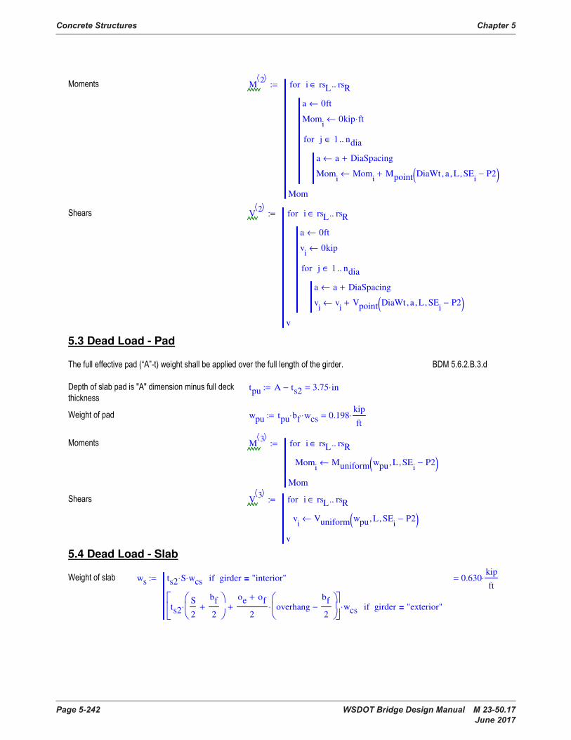
Concrete Structures Chapter 5
Page 5-242 WSDOT Bridge Design Manual M 23-50.17 June 2017
M2
a 0ft←
Momi
0kip ft⋅←
a a DiaSpacing+←
Momi
Momi
Mpoint DiaWt a, L, SEi
P2−, ( )+←
j 1 ndia..∈for
i rsL rsR..∈for
Mom
:=
V2
a 0ft←
vi
0kip←
a a DiaSpacing+←
vi
vi
Vpoint DiaWt a, L, SEi
P2−, ( )+←
j 1 ndia..∈for
i rsL rsR..∈for
v
:=
5.3 Dead Load - Pad
tpu A ts2− 3.75 in⋅=:=
wpu tpu bf⋅ wcs⋅ 0.198kip
ft⋅=:=
M3
Momi
Muniform wpu L, SEi
P2−, ( )←
i rsL rsR..∈for
Mom
:=
V3
vi
Vuniform wpu L, SEi
P2−, ( )←
i rsL rsR..∈for
v
:=
5.4 Dead Load - Slab
ws ts2 S⋅ wcs⋅ girder "interior"=if
ts2S
2
bf
2+
⋅
oe of+
2overhang
bf
2−
⋅+
wcs⋅ girder "exterior"=if
0.630kip
ft⋅=:=
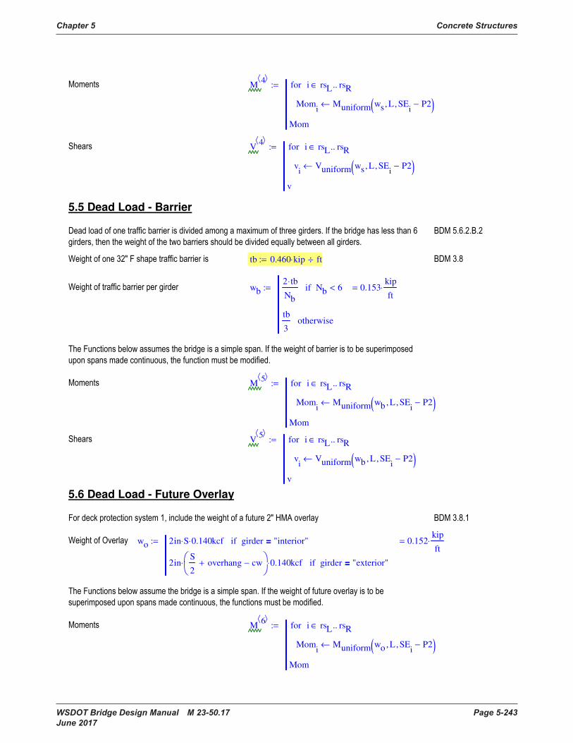
Chapter 5 Concrete Structures
WSDOT Bridge Design Manual M 23-50.17 Page 5-243 June 2017
M4
Momi
Muniform ws L, SEi
P2−, ( )←
i rsL rsR..∈for
Mom
:=
V4
vi
Vuniform ws L, SEi
P2−, ( )←
i rsL rsR..∈for
v
:=
5.5 Dead Load - Barrier
tb 0.460 kip⋅ ft÷:=
wb2 tb⋅
Nb
Nb 6<if
tb
3otherwise
0.153kip
ft⋅=:=
M5
Momi
Muniform wb L, SEi
P2−, ( )←
i rsL rsR..∈for
Mom
:=
V5
vi
Vuniform wb L, SEi
P2−, ( )←
i rsL rsR..∈for
v
:=
5.6 Dead Load - Future Overlay
wo 2in S⋅ 0.140⋅ kcf girder "interior"=if
2inS
2overhang+ cw−
⋅ 0.140⋅ kcf girder "exterior"=if
0.152kip
ft⋅=:=
M6
Momi
Muniform wo L, SEi
P2−, ( )←
i rsL rsR..∈for
Mom
:=
M2
a 0ft←
Momi
0kip ft⋅←
a a DiaSpacing+←
Momi
Momi
Mpoint DiaWt a, L, SEi
P2−, ( )+←
j 1 ndia..∈for
i rsL rsR..∈for
Mom
:=
V2
a 0ft←
vi
0kip←
a a DiaSpacing+←
vi
vi
Vpoint DiaWt a, L, SEi
P2−, ( )+←
j 1 ndia..∈for
i rsL rsR..∈for
v
:=
5.3 Dead Load - Pad
tpu A ts2− 3.75 in⋅=:=
wpu tpu bf⋅ wcs⋅ 0.198kip
ft⋅=:=
M3
Momi
Muniform wpu L, SEi
P2−, ( )←
i rsL rsR..∈for
Mom
:=
V3
vi
Vuniform wpu L, SEi
P2−, ( )←
i rsL rsR..∈for
v
:=
5.4 Dead Load - Slab
ws ts2 S⋅ wcs⋅ girder "interior"=if
ts2S
2
bf
2+
⋅
oe of+
2overhang
bf
2−
⋅+
wcs⋅ girder "exterior"=if
0.630kip
ft⋅=:=
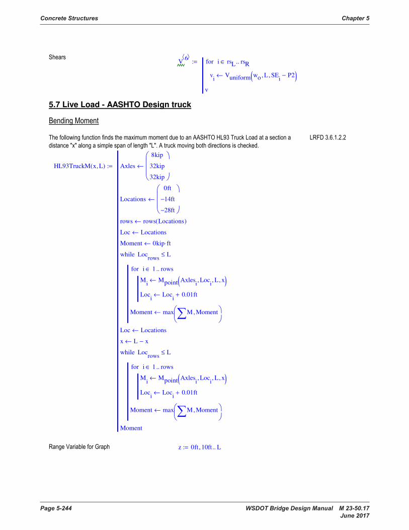
Concrete Structures Chapter 5
Page 5-244 WSDOT Bridge Design Manual M 23-50.17 June 2017
V
6
vi
Vuniform wo L, SEi
P2−, ( )←
i rsL rsR..∈for
v
:=
5.7 Live Load - AASHTO Design truck
HL93TruckM x L, ( ) Axles
8kip
32kip
32kip
←
Locations
0ft
14− ft
28− ft
←
rows rows Locations( )←
Loc Locations←
Moment 0kip ft⋅←
Mi
Mpoint Axlesi
Loci
, L, x, ( )←
Loci
Loci
0.01ft+←
i 1 rows..∈for
Moment max M Moment,
←
Locrows
L≤while
Loc Locations←
x L x−←
Mi
Mpoint Axlesi
Loci
, L, x, ( )←
Loci
Loci
0.01ft+←
i 1 rows..∈for
Moment max M Moment,
←
Locrows
L≤while
Moment
:=
z 0ft 10ft, L..:=
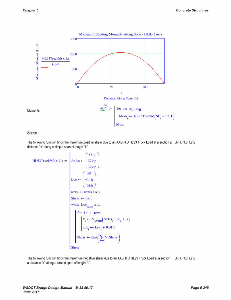
Chapter 5 Concrete Structures
WSDOT Bridge Design Manual M 23-50.17 Page 5-245 June 2017
0 50 1000
1000
2000
3000
Maximum Bending Moments Along Span - HL93 Truck
Distance Along Span (ft)
Max
imu
m M
om
ent
(kip
ft)
HL93TruckM z L, ( )
kip ft⋅
z
M7
Momi
HL93TruckM SEi
P2− L, ( )←
i rsL rsR..∈for
Mom
:=
HL93TruckVP x L, ( ) Axles
8kip
32kip
32kip
←
Loc
0ft
14− ft
28− ft
←
rows rows Loc( )←
Shear 0kip←
Vi
Vpoint Axlesi
Loci
, L, x, ( )←
Loci
Loci
0.01ft+←
i 1 rows..∈for
Shear max V Shear,
←
Locrows
L≤while
Shear
:=
V
6
vi
Vuniform wo L, SEi
P2−, ( )←
i rsL rsR..∈for
v
:=
5.7 Live Load - AASHTO Design truck
HL93TruckM x L, ( ) Axles
8kip
32kip
32kip
←
Locations
0ft
14− ft
28− ft
←
rows rows Locations( )←
Loc Locations←
Moment 0kip ft⋅←
Mi
Mpoint Axlesi
Loci
, L, x, ( )←
Loci
Loci
0.01ft+←
i 1 rows..∈for
Moment max M Moment,
←
Locrows
L≤while
Loc Locations←
x L x−←
Mi
Mpoint Axlesi
Loci
, L, x, ( )←
Loci
Loci
0.01ft+←
i 1 rows..∈for
Moment max M Moment,
←
Locrows
L≤while
Moment
:=
z 0ft 10ft, L..:=
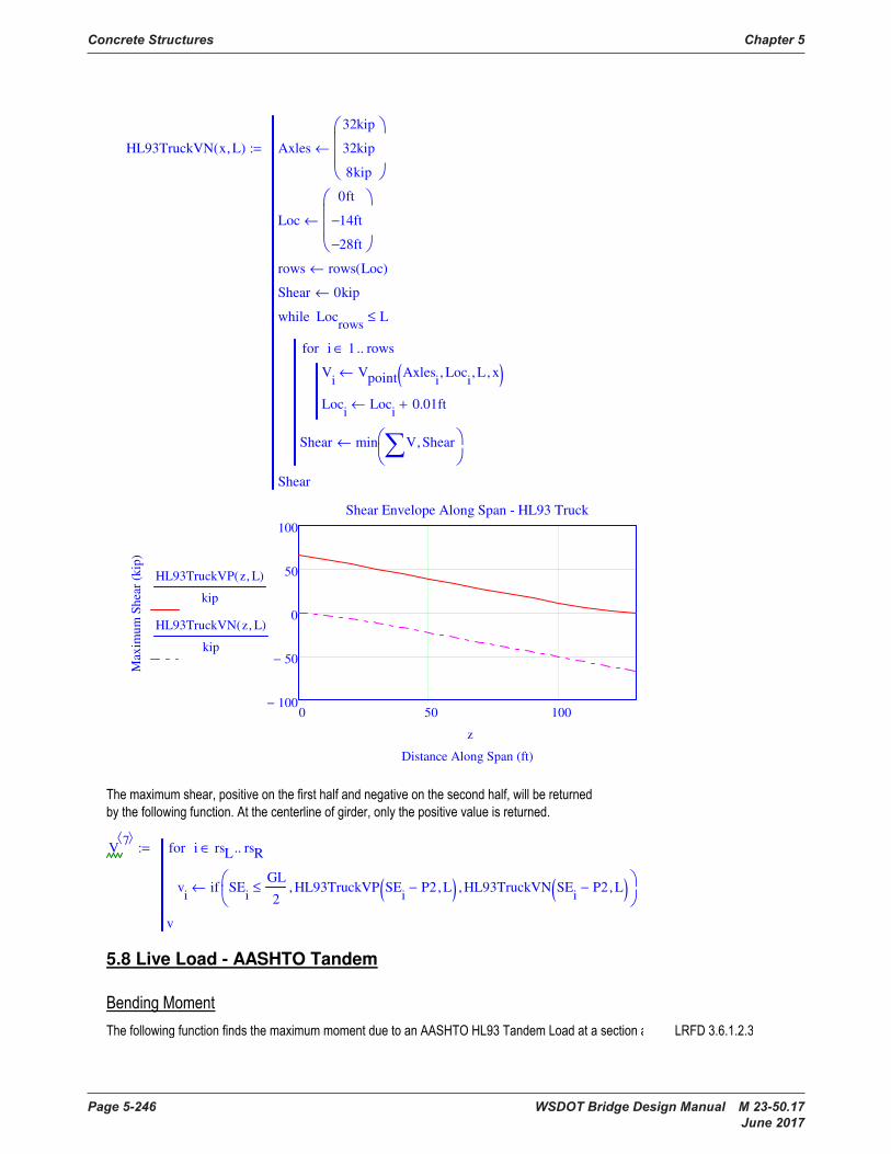
Concrete Structures Chapter 5
Page 5-246 WSDOT Bridge Design Manual M 23-50.17 June 2017
HL93TruckVN x L, ( ) Axles
32kip
32kip
8kip
←
Loc
0ft
14− ft
28− ft
←
rows rows Loc( )←
Shear 0kip←
Vi
Vpoint Axlesi
Loci
, L, x, ( )←
Loci
Loci
0.01ft+←
i 1 rows..∈for
Shear min V Shear,
←
Locrows
L≤while
Shear
:=
0 50 100100−
50−
0
50
100
Shear Envelope Along Span - HL93 Truck
Distance Along Span (ft)
Max
imu
m S
hea
r (k
ip)
HL93TruckVP z L, ( )
kip
HL93TruckVN z L, ( )
kip
z
V7
vi
if SEi
GL
2≤ HL93TruckVP SE
iP2− L, ( ), HL93TruckVN SE
iP2− L, ( ),
←
i rsL rsR..∈for
v
:=
5.8 Live Load - AASHTO Tandem
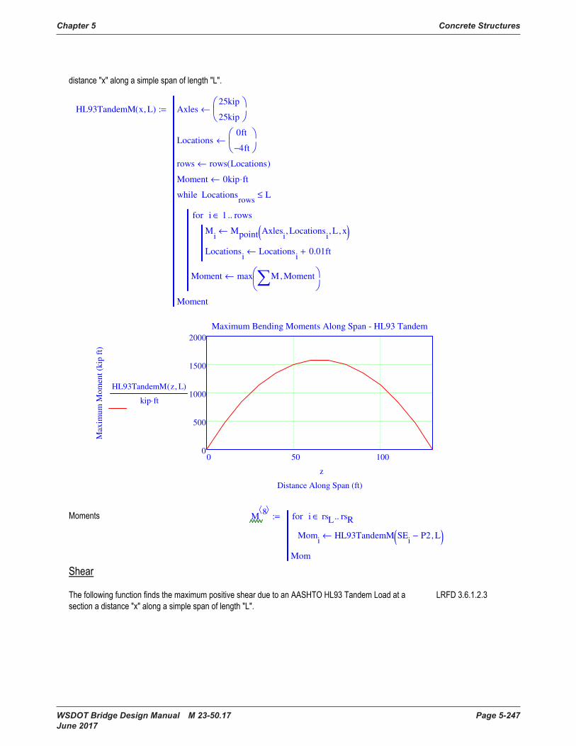
Chapter 5 Concrete Structures
WSDOT Bridge Design Manual M 23-50.17 Page 5-247 June 2017
HL93TandemM x L, ( ) Axles25kip
25kip
←
Locations0ft
4− ft
←
rows rows Locations( )←
Moment 0kip ft⋅←
Mi
Mpoint Axlesi
Locationsi
, L, x, ( )←
Locationsi
Locationsi
0.01ft+←
i 1 rows..∈for
Moment max M Moment,
←
Locationsrows
L≤while
Moment
:=
0 50 1000
500
1000
1500
2000
Maximum Bending Moments Along Span - HL93 Tandem
Distance Along Span (ft)
Max
imu
m M
om
ent
(kip
ft)
HL93TandemM z L, ( )
kip ft⋅
z
M8
Momi
HL93TandemM SEi
P2− L, ( )←
i rsL rsR..∈for
Mom
:=
HL93TruckVN x L, ( ) Axles
32kip
32kip
8kip
←
Loc
0ft
14− ft
28− ft
←
rows rows Loc( )←
Shear 0kip←
Vi
Vpoint Axlesi
Loci
, L, x, ( )←
Loci
Loci
0.01ft+←
i 1 rows..∈for
Shear min V Shear,
←
Locrows
L≤while
Shear
:=
0 50 100100−
50−
0
50
100
Shear Envelope Along Span - HL93 Truck
Distance Along Span (ft)
Max
imu
m S
hea
r (k
ip)
HL93TruckVP z L, ( )
kip
HL93TruckVN z L, ( )
kip
z
V7
vi
if SEi
GL
2≤ HL93TruckVP SE
iP2− L, ( ), HL93TruckVN SE
iP2− L, ( ),
←
i rsL rsR..∈for
v
:=
5.8 Live Load - AASHTO Tandem
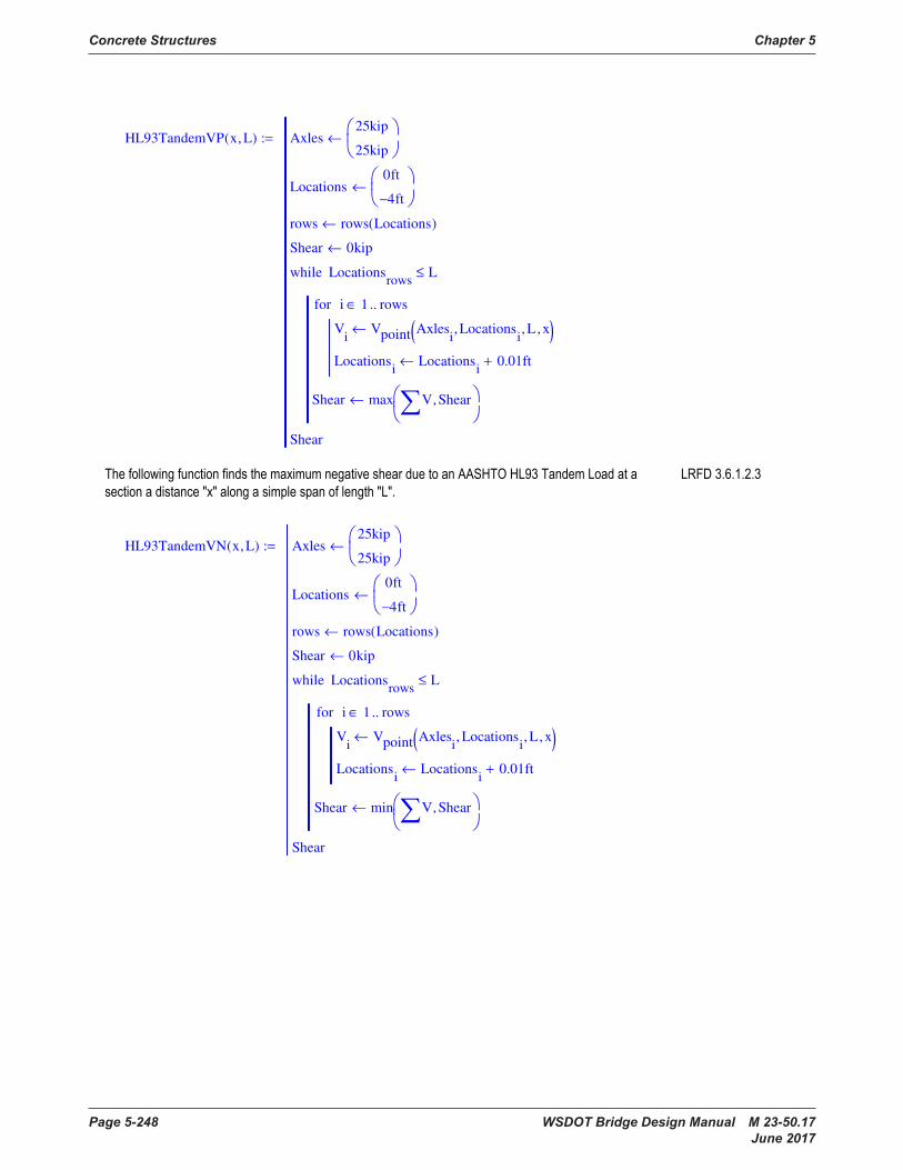
Concrete Structures Chapter 5
Page 5-248 WSDOT Bridge Design Manual M 23-50.17 June 2017
HL93TandemVP x L, ( ) Axles25kip
25kip
←
Locations0ft
4− ft
←
rows rows Locations( )←
Shear 0kip←
Vi
Vpoint Axlesi
Locationsi
, L, x, ( )←
Locationsi
Locationsi
0.01ft+←
i 1 rows..∈for
Shear max V Shear,
←
Locationsrows
L≤while
Shear
:=
HL93TandemVN x L, ( ) Axles25kip
25kip
←
Locations0ft
4− ft
←
rows rows Locations( )←
Shear 0kip←
Vi
Vpoint Axlesi
Locationsi
, L, x, ( )←
Locationsi
Locationsi
0.01ft+←
i 1 rows..∈for
Shear min V Shear,
←
Locationsrows
L≤while
Shear
:=

Chapter 5 Concrete Structures
WSDOT Bridge Design Manual M 23-50.17 Page 5-249 June 2017
0 50 10060−
40−
20−
0
20
40
60
Shear Envelope Along Span - HL93 Tandem
Distance Along Span (ft)
Max
imu
m S
hea
r (k
ip)
HL93TandemVP z L, ( )
kip
HL93TandemVN z L, ( )
kip
z
V8
vi
if SEi
GL
2≤ HL93TandemVP SE
iP2− L, ( ), HL93TandemVN SE
iP2− L, ( ),
←
i rsL rsR..∈for
v
:=
5.9 Live Load - AASHTO Lane Load
M9
Momi
Muniform wlane L, SEi
P2−, ( )←
i rsL rsR..∈for
Mom
:=
V9
vi
if SEi
GL
2≤
wlane L SEi
P2−( )− 2
⋅
2 L⋅,
wlane SEi
P2−( )2
⋅
2 L⋅−,
←
i rsL rsR..∈for
v
:=
5.10 Maximum Live Load including Dynamic Load Allowance, per lane
IM 33 %⋅:=
HL93TandemVP x L, ( ) Axles25kip
25kip
←
Locations0ft
4− ft
←
rows rows Locations( )←
Shear 0kip←
Vi
Vpoint Axlesi
Locationsi
, L, x, ( )←
Locationsi
Locationsi
0.01ft+←
i 1 rows..∈for
Shear max V Shear,
←
Locationsrows
L≤while
Shear
:=
HL93TandemVN x L, ( ) Axles25kip
25kip
←
Locations0ft
4− ft
←
rows rows Locations( )←
Shear 0kip←
Vi
Vpoint Axlesi
Locationsi
, L, x, ( )←
Locationsi
Locationsi
0.01ft+←
i 1 rows..∈for
Shear min V Shear,
←
Locationsrows
L≤while
Shear
:=

Concrete Structures Chapter 5
Page 5-250 WSDOT Bridge Design Manual M 23-50.17 June 2017
M10
Momi
max Mi 7,
Mi 8,
, ( ) 1 IM+( )⋅ Mi 9,
+←
i 1 rows SE( )..∈for
Mom
:=
V10
vi
if SEi
GL
2≤ max V
i 7, V
i 8, , ( ) 1 IM+( )⋅ V
i 9, +, min V
i 7, V
i 8, , ( ) 1 IM+( )⋅ V
i 9, +,
←
i 1 rows SE( ) 1−..∈for
v
:=
Vrows SE( ) 1,
0kip:=
5.11 Fatigue Live Load
HL93TruckMFat x L, ( ) Axles
8kip
32kip
32kip
←
Locations
0ft
14− ft
44− ft
←
rows rows Locations( )←
Loc Locations←
Moment 0kip ft⋅←
Mi
Mpoint Axlesi
Loci
, L, x, ( )←
Loci
Loci
0.01ft+←
i 1 rows..∈for
Moment max M Moment,
←
Locrows
L≤while
Loc Locations←
x L x−←
Mi
Mpoint Axlesi
Loci
, L, x, ( )←
i 1 rows..∈for
Locrows
L≤while
:=
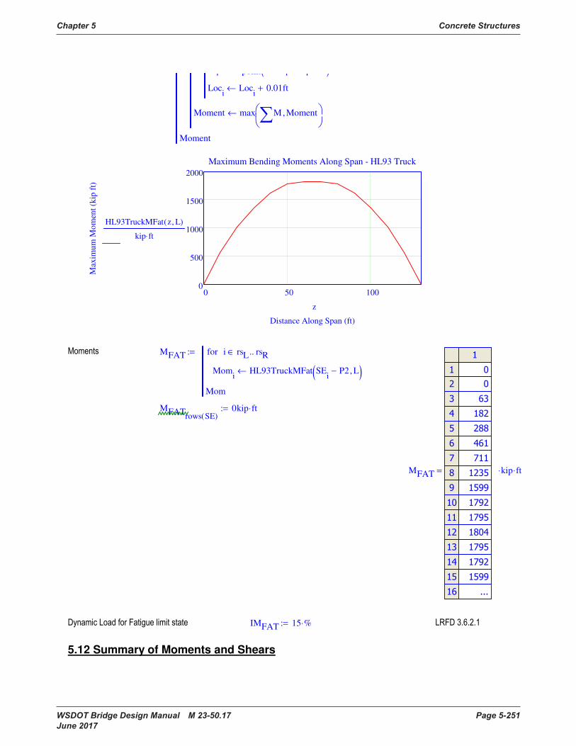
Chapter 5 Concrete Structures
WSDOT Bridge Design Manual M 23-50.17 Page 5-251 June 2017
i point i i( )
Loci
Loci
0.01ft+←
Moment max M Moment,
←
Moment
0 50 1000
500
1000
1500
2000
Maximum Bending Moments Along Span - HL93 Truck
Distance Along Span (ft)
Max
imu
m M
om
ent
(kip
ft)
HL93TruckMFat z L, ( )
kip ft⋅
z
MFAT
Momi
HL93TruckMFat SEi
P2− L, ( )←
i rsL rsR..∈for
Mom
:=
MFATrows SE( )
0kip ft⋅:=
MFAT
kip ft⋅⋅=
IMFAT 15 %⋅:=
5.12 Summary of Moments and Shears
M10
Momi
max Mi 7,
Mi 8,
, ( ) 1 IM+( )⋅ Mi 9,
+←
i 1 rows SE( )..∈for
Mom
:=
V10
vi
if SEi
GL
2≤ max V
i 7, V
i 8, , ( ) 1 IM+( )⋅ V
i 9, +, min V
i 7, V
i 8, , ( ) 1 IM+( )⋅ V
i 9, +,
←
i 1 rows SE( ) 1−..∈for
v
:=
Vrows SE( ) 1,
0kip:=
5.11 Fatigue Live Load
HL93TruckMFat x L, ( ) Axles
8kip
32kip
32kip
←
Locations
0ft
14− ft
44− ft
←
rows rows Locations( )←
Loc Locations←
Moment 0kip ft⋅←
Mi
Mpoint Axlesi
Loci
, L, x, ( )←
Loci
Loci
0.01ft+←
i 1 rows..∈for
Moment max M Moment,
←
Locrows
L≤while
Loc Locations←
x L x−←
Mi
Mpoint Axlesi
Loci
, L, x, ( )←
i 1 rows..∈for
Locrows
L≤while
:=

Concrete Structures Chapter 5
Page 5-252 WSDOT Bridge Design Manual M 23-50.17 June 2017
rsL 2.0=
rsR 22.0=
rp 3.0=
rc 5.0=
rh 10.0=
rm 12.0=
rl1 4.0=
rl2 20.0=
rbL 6.0=
rbR 18.0=
M
kip ft⋅⋅=

Chapter 5 Concrete Structures
WSDOT Bridge Design Manual M 23-50.17 Page 5-253 June 2017
V
kip⋅=
5.13 Moment Distribution of Live Load
dbar overhang cw− 2.75 ft=:=
chk5 1,
if dbar 3ft≤ "OK", "NG", ( ) "OK"=:=
chk5 2,
if Nb 4≥ "OK", "NG", ( ) "OK"=:=
eg Ybs Ybg− 41.84 in⋅=:=
Kg1
nIg Ag eg
2⋅+
⋅ 3599953 in
4⋅=:=
rsL 2.0=
rsR 22.0=
rp 3.0=
rc 5.0=
rh 10.0=
rm 12.0=
rl1 4.0=
rl2 20.0=
rbL 6.0=
rbR 18.0=
M
kip ft⋅⋅=
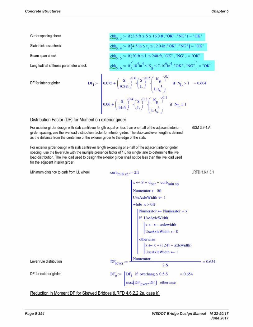
Concrete Structures Chapter 5
Page 5-254 WSDOT Bridge Design Manual M 23-50.17 June 2017
chk5 3,
if 3.5 ft⋅ S≤ 16.0 ft⋅≤ "OK", "NG", ( ) "OK"=:=
chk5 4,
if 4.5 in⋅ ts≤ 12.0 in⋅≤ "OK", "NG", ( ) "OK"=:=
chk5 5,
if 20 ft⋅ L≤ 240 ft⋅≤ "OK", "NG", ( ) "OK"=:=
chk5 6,
if 104in
4Kg≤ 7 10
6⋅ in
4≤ "OK", "NG",
"OK"=:=
DFi 0.075S
9.5 ft⋅
0.6S
L
0.2
⋅
Kg
L ts3
⋅
0.1
⋅+ NL 1>if
0.06S
14 ft⋅
0.4S
L
0.3
⋅
Kg
L ts3
⋅
0.1
⋅+ NL 1=if
0.604=:=
curbmin.sp 2ft:=
DFlever
x S dbar+ curbmin.sp−←
Numerator 0ft←
UseAxleWidth 1←
Numerator Numerator x+←
x x axlewidth−←
UseAxleWidth 0←
UseAxleWidthif
x x 12 ft⋅ axlewidth−( )−←
UseAxleWidth 1←
otherwise
x 0ft>while
Numerator
2 S⋅0.654=:=
DFe DFi overhang 0.5 S⋅≤if
max DFlever DFi, ( ) otherwise
0.654=:=

Chapter 5 Concrete Structures
WSDOT Bridge Design Manual M 23-50.17 Page 5-255 June 2017
chk5 7,
if 30 deg⋅ θsk≤ 60 deg⋅≤ "OK", "NG", ( ) "OK"=:=
chk5 8,
if 3.5 ft⋅ S≤ 16.0 ft⋅≤ "OK", "NG", ( ) "OK"=:=
chk5 9,
if 20 ft⋅ L≤ 240 ft⋅≤ "OK", "NG", ( ) "OK"=:=
chk5 10,
if Nb 4≥ "OK", "NG", ( ) "OK"=:=
c1 0.0 θsk 30 deg⋅<if
0.25Kg
L ts3
⋅
0.25
⋅S
L
0.5
⋅ otherwise
0.090=:=
SK 1 c1 tan min θsk 60deg, ( )( )( )1.5
⋅− 0.961=:=
DF SK DFi⋅ girder "interior"=if
SK DFe⋅ girder "exterior"=if
0.580=:=
DFiFAT
0.06S
14 ft⋅
0.4S
L
0.3
⋅
Kg
L ts3
⋅
0.1
⋅+
1.20.352=:=
DFeFAT DFiFAT overhang 0.5 S⋅≤if
max DFlever DFiFAT, ( ) otherwise
0.654=:=
DFFAT SK DFiFAT⋅ girder "interior"=if
SK DFeFAT⋅ girder "exterior"=if
0.338=:=
5.14 Shear Distribution of Live Load
DFvi max 0.36S
25 ft⋅
+ 0.2S
12 ft⋅
+S
35 ft⋅
2.0
−,
0.707=:=
chk5 3,
if 3.5 ft⋅ S≤ 16.0 ft⋅≤ "OK", "NG", ( ) "OK"=:=
chk5 4,
if 4.5 in⋅ ts≤ 12.0 in⋅≤ "OK", "NG", ( ) "OK"=:=
chk5 5,
if 20 ft⋅ L≤ 240 ft⋅≤ "OK", "NG", ( ) "OK"=:=
chk5 6,
if 104in
4Kg≤ 7 10
6⋅ in
4≤ "OK", "NG",
"OK"=:=
DFi 0.075S
9.5 ft⋅
0.6S
L
0.2
⋅
Kg
L ts3
⋅
0.1
⋅+ NL 1>if
0.06S
14 ft⋅
0.4S
L
0.3
⋅
Kg
L ts3
⋅
0.1
⋅+ NL 1=if
0.604=:=
curbmin.sp 2ft:=
DFlever
x S dbar+ curbmin.sp−←
Numerator 0ft←
UseAxleWidth 1←
Numerator Numerator x+←
x x axlewidth−←
UseAxleWidth 0←
UseAxleWidthif
x x 12 ft⋅ axlewidth−( )−←
UseAxleWidth 1←
otherwise
x 0ft>while
Numerator
2 S⋅0.654=:=
DFe DFi overhang 0.5 S⋅≤if
max DFlever DFi, ( ) otherwise
0.654=:=
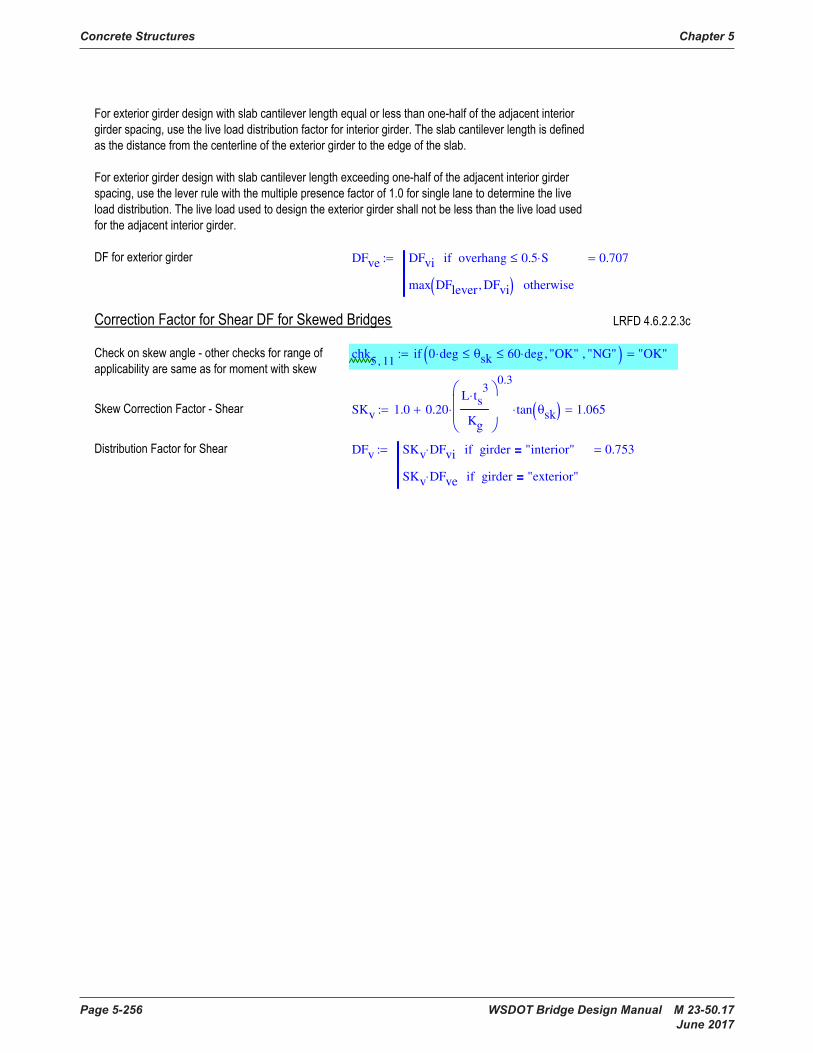
Concrete Structures Chapter 5
Page 5-256 WSDOT Bridge Design Manual M 23-50.17 June 2017
DFve DFvi overhang 0.5 S⋅≤if
max DFlever DFvi, ( ) otherwise
0.707=:=
chk5 11,
if 0 deg⋅ θsk≤ 60 deg⋅≤ "OK", "NG", ( ) "OK"=:=
SKv 1.0 0.20L ts
3⋅
Kg
0.3
⋅ tan θsk( )⋅+ 1.065=:=
DFv SKv DFvi⋅ girder "interior"=if
SKv DFve⋅ girder "exterior"=if
0.753=:=

Chapter 5 Concrete Structures
WSDOT Bridge Design Manual M 23-50.17 Page 5-257 June 2017
6. Computation of Stresses for Dead and Live Loads
6.1 Summary of Stresses
rsL 2.0=
rsR 22.0=
rp 3.0=
rc 5.0=
rh 10.0=
rm 12.0=
rl1 4.0=
rl2 20.0=
rbL 6.0=
rbR 18.0=
Sts 53919 in3
⋅=
Stg 19154 in3
⋅= St 44450 in3
⋅=
Sbg 20593 in3
⋅= Sb 25069 in3
⋅=
DFve DFvi overhang 0.5 S⋅≤if
max DFlever DFvi, ( ) otherwise
0.707=:=
chk5 11,
if 0 deg⋅ θsk≤ 60 deg⋅≤ "OK", "NG", ( ) "OK"=:=
SKv 1.0 0.20L ts
3⋅
Kg
0.3
⋅ tan θsk( )⋅+ 1.065=:=
DFv SKv DFvi⋅ girder "interior"=if
SKv DFve⋅ girder "exterior"=if
0.753=:=

Concrete Structures Chapter 5
Page 5-258 WSDOT Bridge Design Manual M 23-50.17 June 2017
ST
Stressi j,
Mi j,
Stg
−←
i 1 rows SE( )..∈for
j 1 4..∈for
Stressi j,
Mi j,
St
−←
i 1 rows SE( )..∈for
j 5 6..∈for
Stressi j,
Mi j,
DF⋅
St
−←
i 1 rows SE( )..∈for
j 7 10..∈for
Stressi 11,
Mi 11,
Stg
−←
i 1 rows SE( )..∈for
Stress
:= SB
Stressi j,
Mi j,
Sbg
←
i 1 rows SE( )..∈for
j 1 4..∈for
Stressi j,
Mi j,
Sb
←
i 1 rows SE( )..∈for
j 5 6..∈for
Stressi j,
Mi j,
DF⋅
Sb
←
i 1 rows SE( )..∈for
j 7 10..∈for
Stressi 11,
Mi 11,
Sbg
←
i 1 rows SE( )..∈for
Stress
:= SS
Stressi j,
0ksi←
i 1 rows SE( )..∈for
j 1 4..∈for
Stressi j,
Mi j,
Sts
−←
i 1 rows SE( )..∈for
j 5 6..∈for
Stressi j,
Mi j,
DF⋅
Sts
−←
i 1 rows SE( )..∈for
j 7 10..∈for
Stressi 11,
0ksi←
i 1 rows SE( )..∈for
Stress
:=
ST
ksi⋅=
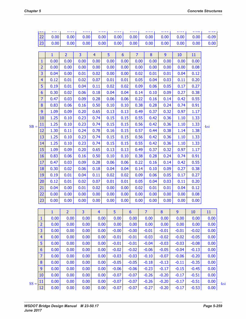
Chapter 5 Concrete Structures
WSDOT Bridge Design Manual M 23-50.17 Page 5-259 June 2017
SB
ksi⋅=
SS
ksi⋅=
ST
Stressi j,
Mi j,
Stg
−←
i 1 rows SE( )..∈for
j 1 4..∈for
Stressi j,
Mi j,
St
−←
i 1 rows SE( )..∈for
j 5 6..∈for
Stressi j,
Mi j,
DF⋅
St
−←
i 1 rows SE( )..∈for
j 7 10..∈for
Stressi 11,
Mi 11,
Stg
−←
i 1 rows SE( )..∈for
Stress
:= SB
Stressi j,
Mi j,
Sbg
←
i 1 rows SE( )..∈for
j 1 4..∈for
Stressi j,
Mi j,
Sb
←
i 1 rows SE( )..∈for
j 5 6..∈for
Stressi j,
Mi j,
DF⋅
Sb
←
i 1 rows SE( )..∈for
j 7 10..∈for
Stressi 11,
Mi 11,
Sbg
←
i 1 rows SE( )..∈for
Stress
:= SS
Stressi j,
0ksi←
i 1 rows SE( )..∈for
j 1 4..∈for
Stressi j,
Mi j,
Sts
−←
i 1 rows SE( )..∈for
j 5 6..∈for
Stressi j,
Mi j,
DF⋅
Sts
−←
i 1 rows SE( )..∈for
j 7 10..∈for
Stressi 11,
0ksi←
i 1 rows SE( )..∈for
Stress
:=
ST
ksi⋅=

Concrete Structures Chapter 5
Page 5-260 WSDOT Bridge Design Manual M 23-50.17 June 2017
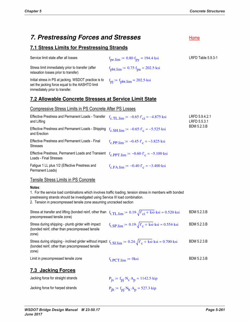
Chapter 5 Concrete Structures
WSDOT Bridge Design Manual M 23-50.17 Page 5-261 June 2017
7. Prestressing Forces and Stresses
7.1 Stress Limits for Prestressing Strands
fpe.lim 0.80 fpy⋅ 194.4 ksi⋅=:=
fpbt.lim 0.75 fpu⋅ 202.5 ksi⋅=:=
fpj fpbt.lim 202.5 ksi⋅=:=
7.2 Allowable Concrete Stresses at Service Limit State
fc.TL.lim 0.65− f'ci⋅ 4.875− ksi⋅=:=
fc.SH.lim 0.65− f'c⋅ 5.525− ksi⋅=:=
fc.PP.lim 0.45− f'c⋅ 3.825− ksi⋅=:=
fc.PPT.lim 0.60− f'c⋅ 5.100− ksi⋅=:=
fc.FA.lim 0.40− f'c⋅ 3.400− ksi⋅=:=
ft.TL.lim 0.19 f'ci ksi÷⋅ ksi⋅ 0.520 ksi⋅=:=
ft.SP.lim 0.19 f'c ksi÷⋅ ksi⋅ 0.554 ksi⋅=:=
ft.SI.lim 0.24 f'c ksi÷⋅ ksi⋅ 0.700 ksi⋅=:=
ft.PCT.lim 0ksi:=
7.3 Jacking Forces
Pjs fpj Ns⋅ Ap⋅ 1142.5 kip⋅=:=
Pjh fpj Nh⋅ Ap⋅ 527.3 kip⋅=:=
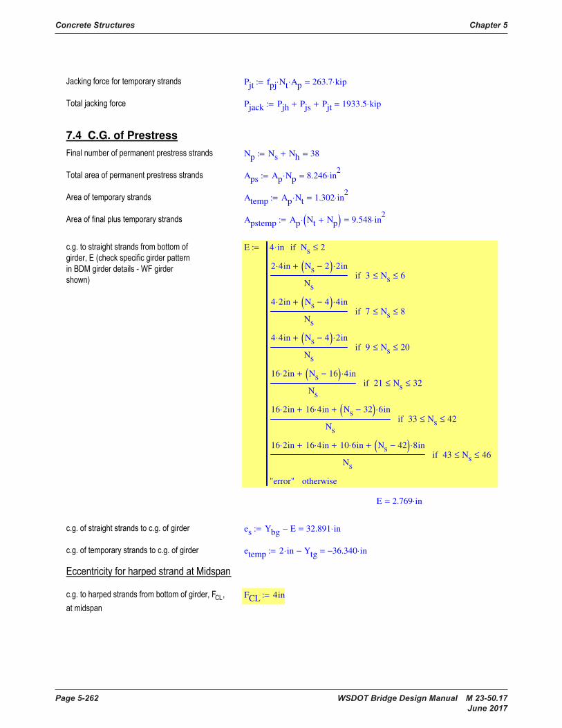
Concrete Structures Chapter 5
Page 5-262 WSDOT Bridge Design Manual M 23-50.17 June 2017
Pjt fpj Nt⋅ Ap⋅ 263.7 kip⋅=:=
Pjack Pjh Pjs+ Pjt+ 1933.5 kip⋅=:=
7.4 C.G. of Prestress
Np Ns Nh+ 38=:=
Aps Ap Np⋅ 8.246 in2
⋅=:=
Atemp Ap Nt⋅ 1.302 in2
⋅=:=
Apstemp Ap Nt Np+( )⋅ 9.548 in2
⋅=:=
E 4 in⋅ Ns 2≤if
2 4⋅ in Ns 2−( ) 2⋅ in+
Ns
3 Ns≤ 6≤if
4 2⋅ in Ns 4−( ) 4⋅ in+
Ns
7 Ns≤ 8≤if
4 4⋅ in Ns 4−( ) 2⋅ in+
Ns
9 Ns≤ 20≤if
16 2⋅ in Ns 16−( ) 4⋅ in+
Ns
21 Ns≤ 32≤if
16 2⋅ in 16 4⋅ in+ Ns 32−( ) 6⋅ in+
Ns
33 Ns≤ 42≤if
16 2⋅ in 16 4⋅ in+ 10 6⋅ in+ Ns 42−( ) 8⋅ in+
Ns
43 Ns≤ 46≤if
"error" otherwise
:=
E 2.769 in⋅=
es Ybg E− 32.891 in⋅=:=
etemp 2 in⋅ Ytg− 36.340− in⋅=:=
FCL 4in:=
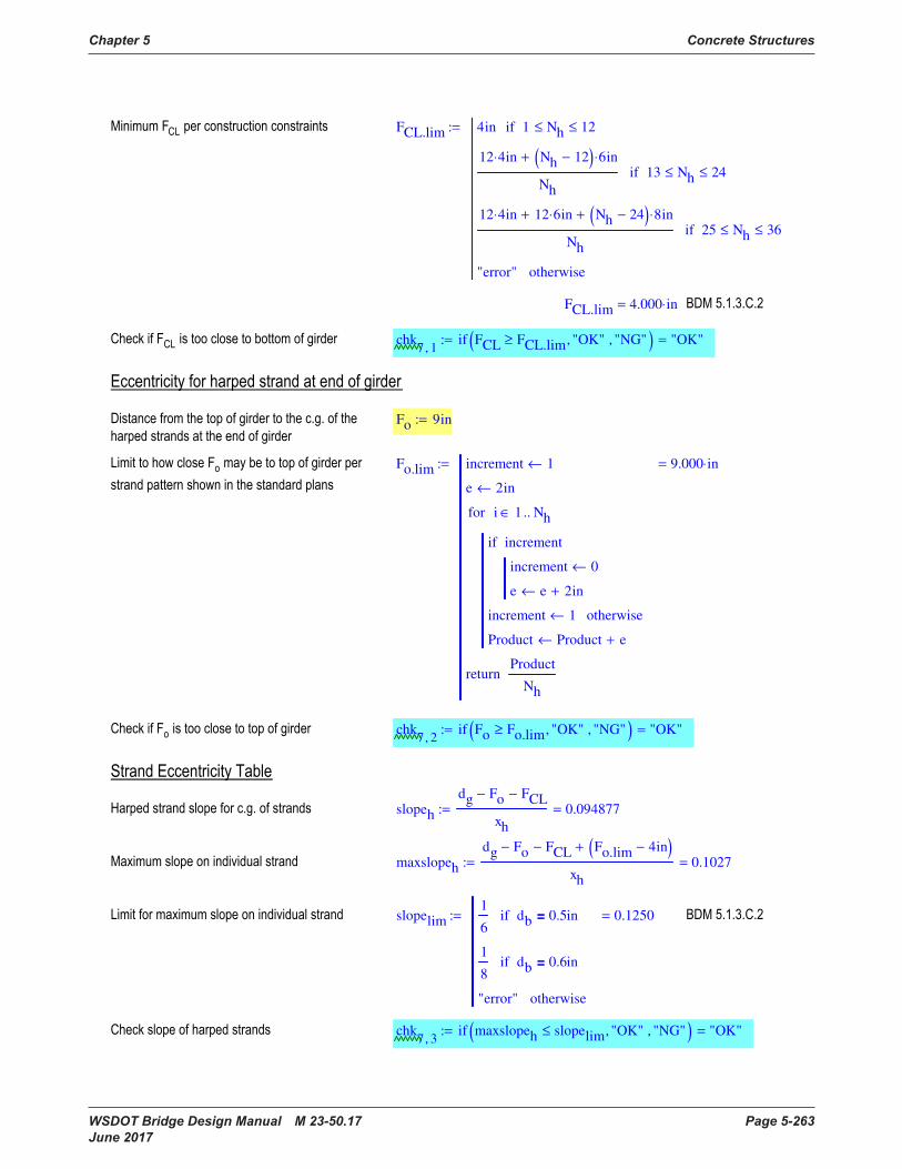
Chapter 5 Concrete Structures
WSDOT Bridge Design Manual M 23-50.17 Page 5-263 June 2017
FCL.lim 4in 1 Nh≤ 12≤if
12 4⋅ in Nh 12−( ) 6⋅ in+
Nh
13 Nh≤ 24≤if
12 4⋅ in 12 6⋅ in+ Nh 24−( ) 8⋅ in+
Nh
25 Nh≤ 36≤if
"error" otherwise
:=
FCL.lim 4.000 in⋅=
chk7 1,
if FCL FCL.lim≥ "OK", "NG", ( ) "OK"=:=
Fo 9in:=
Fo.lim increment 1←
e 2in←
increment 0←
e e 2in+←
incrementif
increment 1← otherwise
Product Product e+←
i 1 Nh..∈for
Product
Nh
return
9.000 in⋅=:=
chk7 2,
if Fo Fo.lim≥ "OK", "NG", ( ) "OK"=:=
slopeh
dg Fo− FCL−
xh
0.094877=:=
maxslopeh
dg Fo− FCL− Fo.lim 4in−( )+
xh
0.1027=:=
slopelim1
6db 0.5in=if
1
8db 0.6in=if
"error" otherwise
0.1250=:=
chk7 3,
if maxslopeh slopelim≤ "OK", "NG", ( ) "OK"=:=
Pjt fpj Nt⋅ Ap⋅ 263.7 kip⋅=:=
Pjack Pjh Pjs+ Pjt+ 1933.5 kip⋅=:=
7.4 C.G. of Prestress
Np Ns Nh+ 38=:=
Aps Ap Np⋅ 8.246 in2
⋅=:=
Atemp Ap Nt⋅ 1.302 in2
⋅=:=
Apstemp Ap Nt Np+( )⋅ 9.548 in2
⋅=:=
E 4 in⋅ Ns 2≤if
2 4⋅ in Ns 2−( ) 2⋅ in+
Ns
3 Ns≤ 6≤if
4 2⋅ in Ns 4−( ) 4⋅ in+
Ns
7 Ns≤ 8≤if
4 4⋅ in Ns 4−( ) 2⋅ in+
Ns
9 Ns≤ 20≤if
16 2⋅ in Ns 16−( ) 4⋅ in+
Ns
21 Ns≤ 32≤if
16 2⋅ in 16 4⋅ in+ Ns 32−( ) 6⋅ in+
Ns
33 Ns≤ 42≤if
16 2⋅ in 16 4⋅ in+ 10 6⋅ in+ Ns 42−( ) 8⋅ in+
Ns
43 Ns≤ 46≤if
"error" otherwise
:=
E 2.769 in⋅=
es Ybg E− 32.891 in⋅=:=
etemp 2 in⋅ Ytg− 36.340− in⋅=:=
FCL 4in:=

Concrete Structures Chapter 5
Page 5-264 WSDOT Bridge Design Manual M 23-50.17 June 2017
Phd Pjh sin atan slopeh( )( )⋅ 49.8 kip⋅=:=
EC
ECi 1,
Ybg FCL slopeh xh SEi
−( )⋅+ −← SEi
xh<if
ECi 1,
Ybg FCL−← xh SEi
≤ GL xh−≤if
ECi 1,
Ybg FCL slopeh SEi
xh+ GL−( )⋅+ −← SEi
GL xh−>if
ECi 2,
es Ns⋅ ECi 1,
Nh⋅+
Np
←
ECi 3,
ECi 2,
Np⋅ etemp Nt⋅+
Np Nt+
←
i 1 rows SE( )..∈for
EC
:=
EC
in⋅=
7.5 Loss of Prestress
to 1day:=
∆fpR0
log24.0 to⋅
day
40−
fpj
fpy
0.55−
⋅ fpj⋅:=

Chapter 5 Concrete Structures
WSDOT Bridge Design Manual M 23-50.17 Page 5-265 June 2017
∆fpR0 1.980− ksi⋅=
fpbt fpj ∆fpR0+ 200.520 ksi⋅=:=
x1 fpbt 0.7 fpu⋅−( )− 11.5− ksi⋅=:=
x2 fpbt 0.7 fpu⋅−( )− 11.5− ksi⋅=:=
P Aps fpbt x1+( )⋅ Atemp fpbt x2+( )⋅+ 1804.6 kip⋅=:=
Given
P Aps fpbt x1+( )⋅ Atemp fpbt x2+( )⋅+=
x1
Ep
Eci
P
Ag
P ECrm 3,
⋅ ECrm 2,
⋅
Ig
+
Mrm 11,
ECrm 2,
⋅
Ig
−
⋅
−=
x2
Ep
Eci
P
Ag
P ECrm 3,
⋅ etemp⋅
Ig
+
Mrm 11,
etemp⋅
Ig
−
⋅
−=
Pps
∆fpES
∆fpEST
Find P x1, x2, ( ):=
Pps 1798.2 kip⋅=
∆fpES 13.055− ksi⋅=
∆fpEST 6.716− ksi⋅=
∆fpED1
Ep
Ec
Mrm 2,
Mrm 3,
+ Mrm 4,
+( ) ECrm 2,
⋅
Ig
⋅ 4.986 ksi⋅=:=
∆fpED2
Ep
Ec
Mrm 5,
Yb Ybg− ECrm 2,
+( )⋅
Ic
⋅ 0.702 ksi⋅=:=
Phd Pjh sin atan slopeh( )( )⋅ 49.8 kip⋅=:=
EC
ECi 1,
Ybg FCL slopeh xh SEi
−( )⋅+ −← SEi
xh<if
ECi 1,
Ybg FCL−← xh SEi
≤ GL xh−≤if
ECi 1,
Ybg FCL slopeh SEi
xh+ GL−( )⋅+ −← SEi
GL xh−>if
ECi 2,
es Ns⋅ ECi 1,
Nh⋅+
Np
←
ECi 3,
ECi 2,
Np⋅ etemp Nt⋅+
Np Nt+
←
i 1 rows SE( )..∈for
EC
:=
EC
in⋅=
7.5 Loss of Prestress
to 1day:=
∆fpR0
log24.0 to⋅
day
40−
fpj
fpy
0.55−
⋅ fpj⋅:=

Concrete Structures Chapter 5
Page 5-266 WSDOT Bridge Design Manual M 23-50.17 June 2017
chk7 4,
if 0.155kcf wcE≥ 0.135kcf≥ "OK", "NG", ( ) "OK"=:=
γh 1.7 0.01 H %÷( )⋅− 0.950=:=
γst5
1 f'ci ksi÷+
0.588=:=
∆fpLTH 3fpbt Aps⋅
ksi Ag⋅
⋅ γh γst⋅ 3 γh⋅ γst⋅+ 0.6+
− ksi 5.278− ksi⋅=:=
∆fpLT 10.0fpbt Aps⋅
ksi Ag⋅
⋅ γh γst⋅ 12.0 γh⋅ γst⋅+ 2.4+
− ksi 19.111− ksi⋅=:=
Ptr Atemp fpbt ∆fpEST+ ∆fpLTH+( )⋅ 245.5 kip⋅=:=
fptr
Ptr
Ag
Ptr etemp⋅ ECrm 2,
⋅
Ig
+ 0.129− ksi⋅=:=
∆fptr
Ep
Ec
fptr⋅ 0.626− ksi⋅=:=
∆fpT ∆fpR0 ∆fpES+ ∆fptr+ ∆fpED1+ ∆fpED2+ ∆fpLT+:=
∆fpT 29.084− ksi⋅= fpe fpj ∆fpT+ 173.416 ksi⋅=:=
chk7 5,
if fpe fpe.lim≤ "OK", "NG", ( ) "OK"=:=
Pe Aps fpe⋅ 1430.0 kip⋅=:=
7.6 Effective Prestress Modifier for Sections within Transfer Length

Chapter 5 Concrete Structures
WSDOT Bridge Design Manual M 23-50.17 Page 5-267 June 2017
TRAN
TRi
SEi
lt
← SEi
lt<if
TRi
1← lt SEi
≤ GL lt−≤if
TRi
GL SEi
−
lt
← GL lt− SEi
<if
i 1 rows SE( )..∈for
TR
:=
TRAN
=
chk7 4,
if 0.155kcf wcE≥ 0.135kcf≥ "OK", "NG", ( ) "OK"=:=
γh 1.7 0.01 H %÷( )⋅− 0.950=:=
γst5
1 f'ci ksi÷+
0.588=:=
∆fpLTH 3fpbt Aps⋅
ksi Ag⋅
⋅ γh γst⋅ 3 γh⋅ γst⋅+ 0.6+
− ksi 5.278− ksi⋅=:=
∆fpLT 10.0fpbt Aps⋅
ksi Ag⋅
⋅ γh γst⋅ 12.0 γh⋅ γst⋅+ 2.4+
− ksi 19.111− ksi⋅=:=
Ptr Atemp fpbt ∆fpEST+ ∆fpLTH+( )⋅ 245.5 kip⋅=:=
fptr
Ptr
Ag
Ptr etemp⋅ ECrm 2,
⋅
Ig
+ 0.129− ksi⋅=:=
∆fptr
Ep
Ec
fptr⋅ 0.626− ksi⋅=:=
∆fpT ∆fpR0 ∆fpES+ ∆fptr+ ∆fpED1+ ∆fpED2+ ∆fpLT+:=
∆fpT 29.084− ksi⋅= fpe fpj ∆fpT+ 173.416 ksi⋅=:=
chk7 5,
if fpe fpe.lim≤ "OK", "NG", ( ) "OK"=:=
Pe Aps fpe⋅ 1430.0 kip⋅=:=
7.6 Effective Prestress Modifier for Sections within Transfer Length
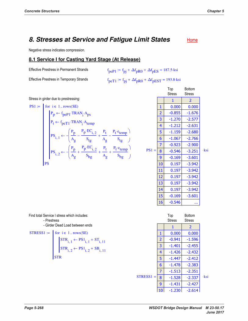
Concrete Structures Chapter 5
Page 5-268 WSDOT Bridge Design Manual M 23-50.17 June 2017
8. Stresses at Service and Fatigue Limit States
8.1 Service I for Casting Yard Stage (At Release)
fpeP1 fpj ∆fpR0+ ∆fpES+ 187.5 ksi⋅=:=
fpeT1 fpj ∆fpR0+ ∆fpEST+ 193.8 ksi⋅=:=
PS1
Pp fpeP1 TRANi
⋅ Aps⋅←
Pt fpeT1 TRANi
⋅ Atemp⋅←
PSi 1,
Pp
Ag
Pp ECi 2,
⋅
Stg
−
Pt
Ag
+
Pt etemp⋅
Stg
−
−←
PSi 2,
Pp
Ag
Pp ECi 2,
⋅
Sbg
+
Pt
Ag
+
Pt etemp⋅
Sbg
+
−←
i 1 rows SE( )..∈for
PS
:=
PS1
ksi⋅=
STRESS1
STRi 1,
PS1i 1,
STi 11,
+←
STRi 2,
PS1i 2,
SBi 11,
+←
i 1 rows SE( )..∈for
STR
:=
STRESS1
ksi⋅=

Chapter 5 Concrete Structures
WSDOT Bridge Design Manual M 23-50.17 Page 5-269 June 2017
fc.TL.lim 4.875− ksi⋅=
ft.TL.lim 0.520 ksi⋅=
chk8 1,
if min STRESS1( ) fc.TL.lim≥ "OK", "NG", ( ) "OK"=:=
chk8 2,
if max STRESS1( ) ft.TL.lim≤ "OK", "NG", ( ) "OK"=:=
8.2 Service I after Temporary Strand Removal
fpeP2 fpj ∆fpR0+ ∆fpES+ ∆fpLTH+ ∆fptr+ 181.6 ksi⋅=:=
PS2
Pp fpeP2 TRANi
⋅ Aps⋅←
PSi 1,
Pp
Ag
Pp ECi 2,
⋅
Stg
−
−←
PSi 2,
Pp
Ag
Pp ECi 2,
⋅
Sbg
+
−←
i 1 rows SE( )..∈for
PS
:=
PS2
ksi⋅=
8. Stresses at Service and Fatigue Limit States
8.1 Service I for Casting Yard Stage (At Release)
fpeP1 fpj ∆fpR0+ ∆fpES+ 187.5 ksi⋅=:=
fpeT1 fpj ∆fpR0+ ∆fpEST+ 193.8 ksi⋅=:=
PS1
Pp fpeP1 TRANi
⋅ Aps⋅←
Pt fpeT1 TRANi
⋅ Atemp⋅←
PSi 1,
Pp
Ag
Pp ECi 2,
⋅
Stg
−
Pt
Ag
+
Pt etemp⋅
Stg
−
−←
PSi 2,
Pp
Ag
Pp ECi 2,
⋅
Sbg
+
Pt
Ag
+
Pt etemp⋅
Sbg
+
−←
i 1 rows SE( )..∈for
PS
:=
PS1
ksi⋅=
STRESS1
STRi 1,
PS1i 1,
STi 11,
+←
STRi 2,
PS1i 2,
SBi 11,
+←
i 1 rows SE( )..∈for
STR
:=
STRESS1
ksi⋅=
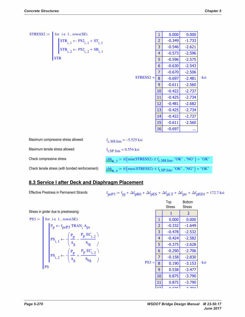
Concrete Structures Chapter 5
Page 5-270 WSDOT Bridge Design Manual M 23-50.17 June 2017
STRESS2
STRi 1,
PS2i 1,
STi 1,
+←
STRi 2,
PS2i 2,
SBi 1,
+←
i 1 rows SE( )..∈for
STR
:=
STRESS2
ksi⋅=
fc.SH.lim 5.525− ksi⋅=
ft.SP.lim 0.554 ksi⋅=
chk8 3,
if min STRESS2( ) fc.SH.lim≥ "OK", "NG", ( ) "OK"=:=
chk8 4,
if max STRESS2( ) ft.SP.lim≤ "OK", "NG", ( ) "OK"=:=
8.3 Service I after Deck and Diaphragm Placement
fpeP3 fpj ∆fpR0+ ∆fpES+ ∆fpLT+ ∆fptr+ ∆fpED1+ 172.7 ksi⋅=:=
PS3
Pp fpeP3 TRANi
⋅ Aps⋅←
PSi 1,
Pp
Ag
Pp ECi 2,
⋅
Stg
−
−←
PSi 2,
Pp
Ag
Pp ECi 2,
⋅
Sbg
+
−←
i 1 rows SE( )..∈for
PS
:=
PS3
ksi⋅=
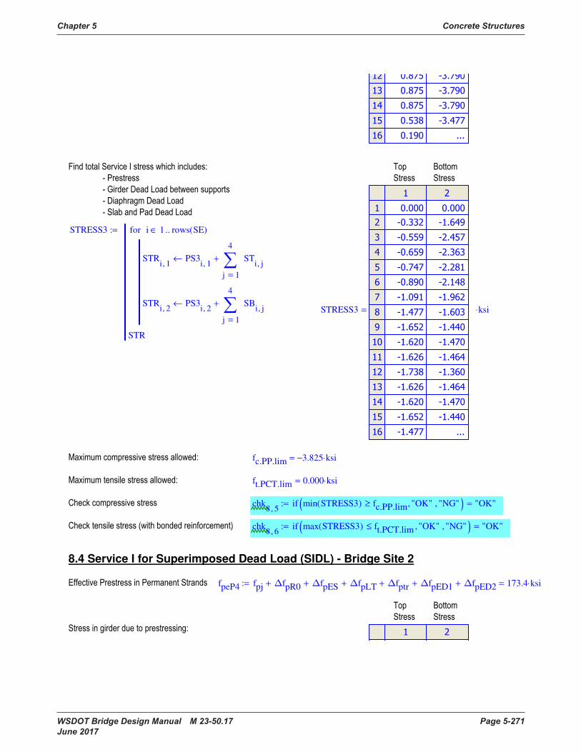
Chapter 5 Concrete Structures
WSDOT Bridge Design Manual M 23-50.17 Page 5-271 June 2017
STRESS3
STRi 1,
PS3i 1,
1
4
j
STi j,
=
+←
STRi 2,
PS3i 2,
1
4
j
SBi j,
=
+←
i 1 rows SE( )..∈for
STR
:=
STRESS3
ksi⋅=
fc.PP.lim 3.825− ksi⋅=
ft.PCT.lim 0.000 ksi⋅=
chk8 5,
if min STRESS3( ) fc.PP.lim≥ "OK", "NG", ( ) "OK"=:=
chk8 6,
if max STRESS3( ) ft.PCT.lim≤ "OK", "NG", ( ) "OK"=:=
8.4 Service I for Superimposed Dead Load (SIDL) - Bridge Site 2
fpeP4 fpj ∆fpR0+ ∆fpES+ ∆fpLT+ ∆fptr+ ∆fpED1+ ∆fpED2+ 173.4 ksi⋅=:=
STRESS2
STRi 1,
PS2i 1,
STi 1,
+←
STRi 2,
PS2i 2,
SBi 1,
+←
i 1 rows SE( )..∈for
STR
:=
STRESS2
ksi⋅=
fc.SH.lim 5.525− ksi⋅=
ft.SP.lim 0.554 ksi⋅=
chk8 3,
if min STRESS2( ) fc.SH.lim≥ "OK", "NG", ( ) "OK"=:=
chk8 4,
if max STRESS2( ) ft.SP.lim≤ "OK", "NG", ( ) "OK"=:=
8.3 Service I after Deck and Diaphragm Placement
fpeP3 fpj ∆fpR0+ ∆fpES+ ∆fpLT+ ∆fptr+ ∆fpED1+ 172.7 ksi⋅=:=
PS3
Pp fpeP3 TRANi
⋅ Aps⋅←
PSi 1,
Pp
Ag
Pp ECi 2,
⋅
Stg
−
−←
PSi 2,
Pp
Ag
Pp ECi 2,
⋅
Sbg
+
−←
i 1 rows SE( )..∈for
PS
:=
PS3
ksi⋅=

Concrete Structures Chapter 5
Page 5-272 WSDOT Bridge Design Manual M 23-50.17 June 2017
PS4
Pp fpeP4 TRANi
⋅ Aps⋅←
PSi 1,
Pp
Ag
Pp ECi 2,
⋅
Stg
−
−←
PSi 2,
Pp
Ag
Pp ECi 2,
⋅
Sbg
+
−←
i 1 rows SE( )..∈for
PS
:=
PS4
ksi⋅=
STRESS4
STRi 1,
PS4i 1,
1
5
j
STi j,
=
+←
STRi 2,
PS4i 2,
1
5
j
SBi j,
=
+←
STRi 3,
1
5
j
SSi j,
=
←
i 1 rows SE( )..∈for
STR
:=
STRESS4
ksi⋅=
fc.PP.lim 3.825− ksi⋅=
ft.PCT.lim 0.000 ksi⋅=
( )

Chapter 5 Concrete Structures
WSDOT Bridge Design Manual M 23-50.17 Page 5-273 June 2017
chk8 7,
if min STRESS41
STRESS42
, ( ) fc.PP.lim≥ "OK", "NG",
"OK"=:=
chk8 8,
if max STRESS41
STRESS42
, ( ) ft.PCT.lim≤ "OK", "NG",
"OK"=:=
8.5 Service I for Final with Live Load - Bridge Site 3 - Compressive Stresses
fpeP5 fpe 173.4 ksi⋅=:=
PS5
Pp fpeP5 TRANi
⋅ Aps⋅←
PSi 1,
Pp
Ag
Pp ECi 2,
⋅
Stg
−
−←
PSi 2,
Pp
Ag
Pp ECi 2,
⋅
Sbg
+
−←
i 1 rows SE( )..∈for
PS
:=
PS5
ksi⋅=
PS4
Pp fpeP4 TRANi
⋅ Aps⋅←
PSi 1,
Pp
Ag
Pp ECi 2,
⋅
Stg
−
−←
PSi 2,
Pp
Ag
Pp ECi 2,
⋅
Sbg
+
−←
i 1 rows SE( )..∈for
PS
:=
PS4
ksi⋅=
STRESS4
STRi 1,
PS4i 1,
1
5
j
STi j,
=
+←
STRi 2,
PS4i 2,
1
5
j
SBi j,
=
+←
STRi 3,
1
5
j
SSi j,
=
←
i 1 rows SE( )..∈for
STR
:=
STRESS4
ksi⋅=
fc.PP.lim 3.825− ksi⋅=
ft.PCT.lim 0.000 ksi⋅=
( )

Concrete Structures Chapter 5
Page 5-274 WSDOT Bridge Design Manual M 23-50.17 June 2017
STRESS5
STRi 1,
PS5i 1,
1
6
j
STi j,
=
+ STi 10,
+←
STRi 2,
PS5i 2,
1
6
j
SBi j,
=
+←
STRi 3,
1
6
j
SSi j,
=
SSi 10,
+←
i 1 rows SE( )..∈for
STR
:=
STRESS5
ksi⋅=
fc.PPT.lim 5.100− ksi⋅=
chk8 9,
if min STRESS51
STRESS52
, ( ) fc.PPT.lim≥ "OK", "NG",
"OK"=:=
8.6 Fatigue I for Final with Live Load - Bridge Site 3 - Compressive Stresses
SFATLL
Stressi 1,
γLLfat MFATi
⋅ DFFAT⋅ 1 IMFAT+( )⋅
St
−←
Stressi 2,
γLLfat MFATi
⋅ DFFAT⋅ 1 IMFAT+( )⋅
Sb
←
i 1 rows SE( )..∈for
Stress
:=
SFATLL
ksi⋅=
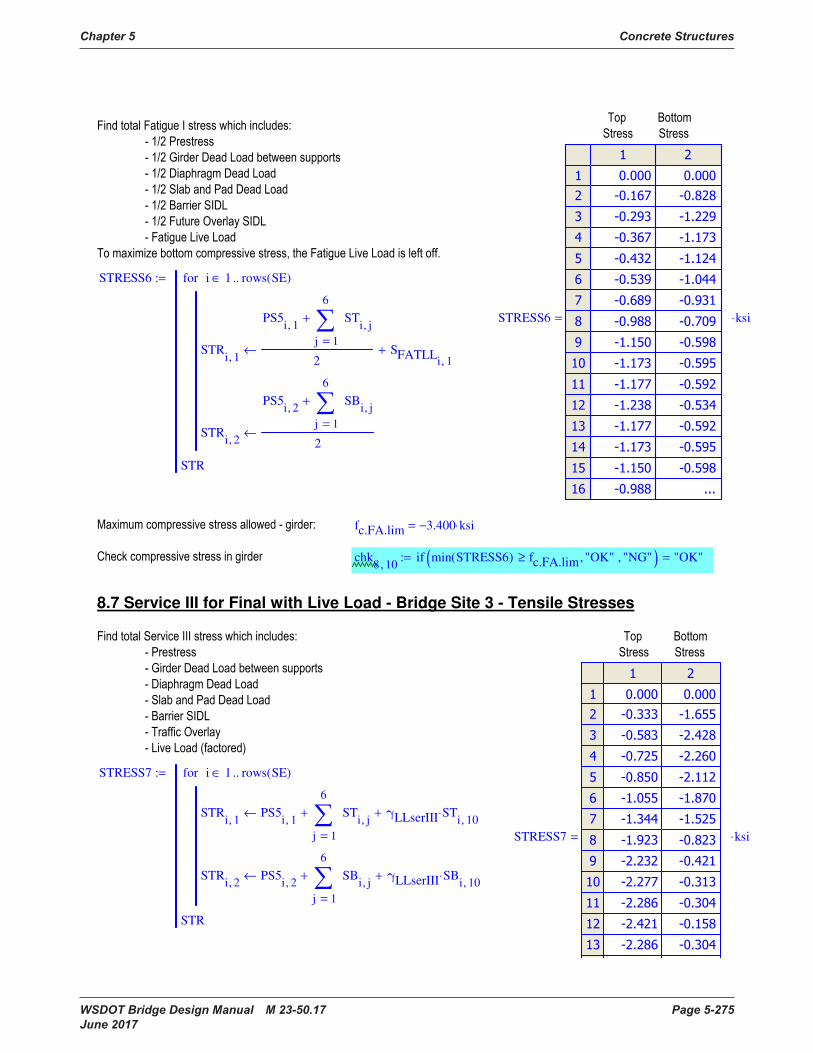
Chapter 5 Concrete Structures
WSDOT Bridge Design Manual M 23-50.17 Page 5-275 June 2017
STRESS6
STRi 1,
PS5i 1,
1
6
j
STi j,
=
+
2SFATLL
i 1,
+←
STRi 2,
PS5i 2,
1
6
j
SBi j,
=
+
2←
i 1 rows SE( )..∈for
STR
:=
STRESS6
ksi⋅=
fc.FA.lim 3.400− ksi⋅=
chk8 10,
if min STRESS6( ) fc.FA.lim≥ "OK", "NG", ( ) "OK"=:=
8.7 Service III for Final with Live Load - Bridge Site 3 - Tensile Stresses
STRESS7
STRi 1,
PS5i 1,
1
6
j
STi j,
=
+ γLLserIII STi 10,
⋅+←
STRi 2,
PS5i 2,
1
6
j
SBi j,
=
+ γLLserIII SBi 10,
⋅+←
i 1 rows SE( )..∈for
STR
:=
STRESS7
ksi⋅=
STRESS5
STRi 1,
PS5i 1,
1
6
j
STi j,
=
+ STi 10,
+←
STRi 2,
PS5i 2,
1
6
j
SBi j,
=
+←
STRi 3,
1
6
j
SSi j,
=
SSi 10,
+←
i 1 rows SE( )..∈for
STR
:=
STRESS5
ksi⋅=
fc.PPT.lim 5.100− ksi⋅=
chk8 9,
if min STRESS51
STRESS52
, ( ) fc.PPT.lim≥ "OK", "NG",
"OK"=:=
8.6 Fatigue I for Final with Live Load - Bridge Site 3 - Compressive Stresses
SFATLL
Stressi 1,
γLLfat MFATi
⋅ DFFAT⋅ 1 IMFAT+( )⋅
St
−←
Stressi 2,
γLLfat MFATi
⋅ DFFAT⋅ 1 IMFAT+( )⋅
Sb
←
i 1 rows SE( )..∈for
Stress
:=
SFATLL
ksi⋅=

Concrete Structures Chapter 5
Page 5-276 WSDOT Bridge Design Manual M 23-50.17 June 2017
ft.PCT.lim 0.000 ksi⋅=
chk8 11,
if max STRESS71
STRESS72
, ( ) ft.PCT.lim≤ "OK", "NG",
"OK"=:=
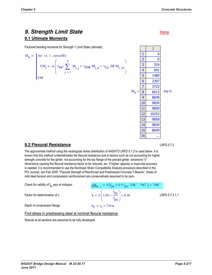
Chapter 5 Concrete Structures
WSDOT Bridge Design Manual M 23-50.17 Page 5-277 June 2017
9. Strength Limit State 9.1 Ultimate Moments
Mu
UMi
η γDC
1
5
j
Mi j,
=
⋅ γDW Mi 6,
⋅+ γLL DF⋅ Mi 10,
⋅+
⋅←
i 1 rows SE( )..∈for
UM
:=
Mu
kip ft⋅⋅=
9.2 Flexural Resistance
chk9 1,
if fpe 0.5 fpu⋅≥ "OK", "NG", ( ) "OK"=:=
k 2 1.04fpy
fpu
−
⋅ 0.28=:=
hf ts 7.0 in⋅=:=
ft.PCT.lim 0.000 ksi⋅=
chk8 11,
if max STRESS71
STRESS72
, ( ) ft.PCT.lim≤ "OK", "NG",
"OK"=:=
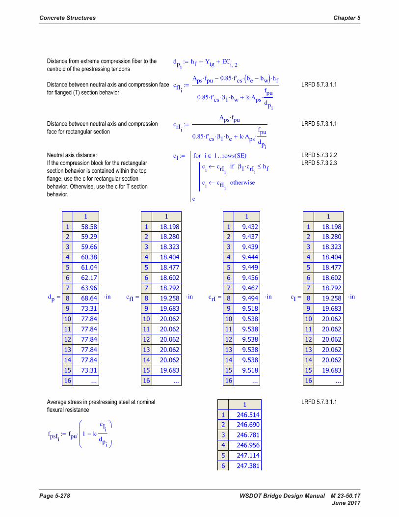
Concrete Structures Chapter 5
Page 5-278 WSDOT Bridge Design Manual M 23-50.17 June 2017
dpi
hf Ytg+ ECi 2,
+:=
cfIi
Aps fpu⋅ 0.85 f'cs⋅ be bw−( )⋅ hf⋅−
0.85 f'cs⋅ β1⋅ bw⋅ k Aps⋅
fpu
dpi
⋅+
:=
crIi
Aps fpu⋅
0.85 f'cs⋅ β1⋅ be⋅ k Aps⋅
fpu
dpi
⋅+
:=
cI
ci
crIi
← β1 crIi
⋅ hf≤if
ci
cfIi
← otherwise
i 1 rows SE( )..∈for
c
:=
dp
in⋅= cfI
in⋅= crI
in⋅= cI
in⋅=
fpsIi
fpu 1 k
cIi
dpi
⋅−
⋅:=
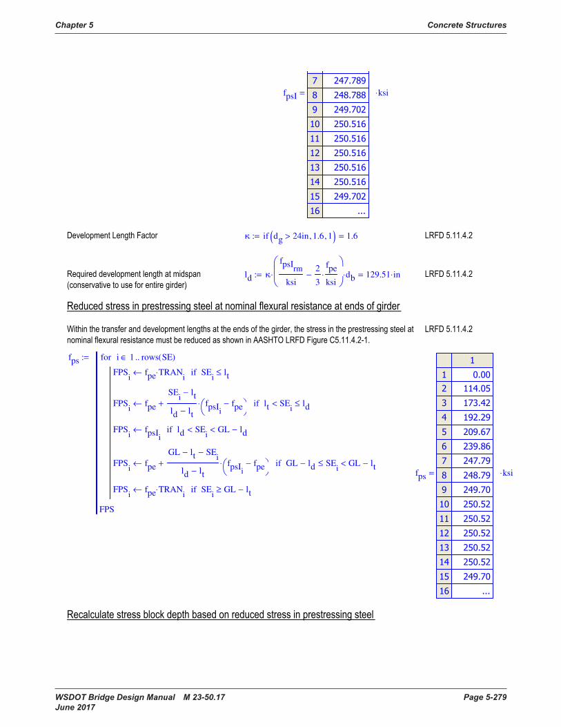
Chapter 5 Concrete Structures
WSDOT Bridge Design Manual M 23-50.17 Page 5-279 June 2017
fpsI
ksi⋅=
κ if dg 24in> 1.6, 1, ( ) 1.6=:=
ld κ
fpsIrm
ksi
2
3
fpe
ksi⋅−
⋅ db⋅ 129.51 in⋅=:=
fps
FPSi
fpe TRANi
⋅← SEi
lt≤if
FPSi
fpe
SEi
lt−
ld lt−
fpsIi
fpe−
⋅+← lt SEi
< ld≤if
FPSi
fpsIi
← ld SEi
< GL ld−<if
FPSi
fpe
GL lt− SEi
−
ld lt−
fpsIi
fpe−
⋅+← GL ld− SEi
≤ GL lt−<if
FPSi
fpe TRANi
⋅← SEi
GL lt−≥if
i 1 rows SE( )..∈for
FPS
:=
fps
ksi⋅=
( )
dpi
hf Ytg+ ECi 2,
+:=
cfIi
Aps fpu⋅ 0.85 f'cs⋅ be bw−( )⋅ hf⋅−
0.85 f'cs⋅ β1⋅ bw⋅ k Aps⋅
fpu
dpi
⋅+
:=
crIi
Aps fpu⋅
0.85 f'cs⋅ β1⋅ be⋅ k Aps⋅
fpu
dpi
⋅+
:=
cI
ci
crIi
← β1 crIi
⋅ hf≤if
ci
cfIi
← otherwise
i 1 rows SE( )..∈for
c
:=
dp
in⋅= cfI
in⋅= crI
in⋅= cI
in⋅=
fpsIi
fpu 1 k
cIi
dpi
⋅−
⋅:=
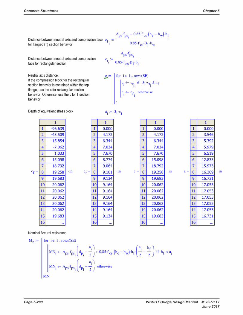
Concrete Structures Chapter 5
Page 5-280 WSDOT Bridge Design Manual M 23-50.17 June 2017
cfi
Aps fpsi
⋅ 0.85 f'cs⋅ be bw−( )⋅ hf⋅−
0.85 f'cs⋅ β1⋅ bw⋅
:=
cri
Aps fpsi
⋅
0.85 f'cs⋅ β1⋅ be⋅
:=
c
ci
cri
← β1 cri
⋅ hf≤if
ci
cfi
← otherwise
i 1 rows SE( )..∈for
c
:=
ai
β1 ci
⋅:=
cf
in⋅= cr
in⋅= c
in⋅= a
in⋅=
Mn
MNi
Aps fpsi
⋅ dpi
ai
2−
⋅ 0.85 f'cs⋅ be bw−( )⋅ hf⋅
ai
2
hf
2−
⋅+← hf ai
<if
MNi
Aps fpsi
⋅ dpi
ai
2−
⋅← otherwise
i 1 rows SE( )..∈for
MN
:=
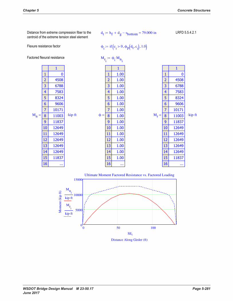
Chapter 5 Concrete Structures
WSDOT Bridge Design Manual M 23-50.17 Page 5-281 June 2017
dt hf dg+ sbottom− 79.000 in⋅=:=
ϕi
if ci
0> ϕp dt ci
, ( ), 1.0, ( ):=
Mri
ϕi
Mni
⋅:=
Mn
kip ft⋅⋅= ϕ
= Mr
kip ft⋅⋅=
0 50 1000
5000
10000
15000
Ultimate Moment Factored Resistance vs. Factored Loading
Distance Along Girder (ft)
Mo
men
t (k
ip f
t)
Mui
kip ft⋅
Mri
kip ft⋅
SEi
cfi
Aps fpsi
⋅ 0.85 f'cs⋅ be bw−( )⋅ hf⋅−
0.85 f'cs⋅ β1⋅ bw⋅
:=
cri
Aps fpsi
⋅
0.85 f'cs⋅ β1⋅ be⋅
:=
c
ci
cri
← β1 cri
⋅ hf≤if
ci
cfi
← otherwise
i 1 rows SE( )..∈for
c
:=
ai
β1 ci
⋅:=
cf
in⋅= cr
in⋅= c
in⋅= a
in⋅=
Mn
MNi
Aps fpsi
⋅ dpi
ai
2−
⋅ 0.85 f'cs⋅ be bw−( )⋅ hf⋅
ai
2
hf
2−
⋅+← hf ai
<if
MNi
Aps fpsi
⋅ dpi
ai
2−
⋅← otherwise
i 1 rows SE( )..∈for
MN
:=
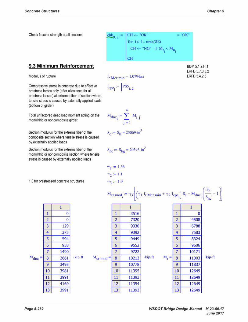
Concrete Structures Chapter 5
Page 5-282 WSDOT Bridge Design Manual M 23-50.17 June 2017
chk9 2,
CH "OK"←
CH "NG"← Mri
Mui
<if
i 1 rows SE( )..∈for
CH
"OK"=:=
9.3 Minimum Reinforcement
fr.Mcr.min 1.079 ksi⋅=
fcpei
PS5i 2,
:=
Mdnci
1
4
j
Mi j,
=
:=
Sc Sb 25069 in3
⋅=:=
Snc Sbg 20593 in3
⋅=:=
γ1 1.56:=
γ2 1.1:=
γ3 1.0:=
Mcr.modi
γ3 γ1 fr.Mcr.min⋅ γ2 fcpei
⋅+
Sc⋅ Mdnci
Sc
Snc
1−
⋅−
⋅:=
Mdnc
kip ft⋅⋅= Mcr.mod
kip ft⋅⋅= Mr
kip ft⋅⋅=

Chapter 5 Concrete Structures
WSDOT Bridge Design Manual M 23-50.17 Page 5-283 June 2017
chk9 3,
CH "OK"←
CH "NG"← Mri
min Mcr.modi
1.33 Mui
⋅,
<if
i 1 rows SE( )..∈for
CH
"OK"=:=
chk9 2,
CH "OK"←
CH "NG"← Mri
Mui
<if
i 1 rows SE( )..∈for
CH
"OK"=:=
9.3 Minimum Reinforcement
fr.Mcr.min 1.079 ksi⋅=
fcpei
PS5i 2,
:=
Mdnci
1
4
j
Mi j,
=
:=
Sc Sb 25069 in3
⋅=:=
Snc Sbg 20593 in3
⋅=:=
γ1 1.56:=
γ2 1.1:=
γ3 1.0:=
Mcr.modi
γ3 γ1 fr.Mcr.min⋅ γ2 fcpei
⋅+
Sc⋅ Mdnci
Sc
Snc
1−
⋅−
⋅:=
Mdnc
kip ft⋅⋅= Mcr.mod
kip ft⋅⋅= Mr
kip ft⋅⋅=

Concrete Structures Chapter 5
Page 5-284 WSDOT Bridge Design Manual M 23-50.17 June 2017
10. Shear & Longitudinal Reinforcement Design
10.1 Factored Shear Loads
Vu
UVi
η γDC
1
5
j
Vi j,
=
⋅ γDW Vi 6,
⋅+ γLL DFv⋅ Vi 10,
⋅+
⋅←
i 1 rows SE( )..∈for
UV
:=
Vu
kip⋅=
10.2 Critical Section Location
dei
dpi
:=
chk10 1,
ifL
22 dersL
⋅≥ "OK", "NG",
"OK"=:=
dvIi
Mni
Aps fpsi
⋅
:=
h dg ts+ 81.0 in⋅=:=
dvi
max dvIi
0.9 dei
⋅, 0.72 h⋅,
:=

Chapter 5 Concrete Structures
WSDOT Bridge Design Manual M 23-50.17 Page 5-285 June 2017
de
in⋅= dvI
in⋅= dv
in⋅=
dc dvrsL4.8600 ft=:=
chk10 2,
if dest dc= "OK", "NG", ( ) "OK"=:=
10.3 Shear Design
θharp atan slopeh( ) 5.420 deg⋅=:=
Phi
fpe TRANi
⋅ Ap⋅ Nh⋅:=
Vpi
0kip 0.4 GL⋅ SEi
≤ 0.6 GL⋅≤if
Phi
sin θharp( )⋅ otherwise
:=
fpo 0.7 fpu⋅ 189.0 ksi⋅=:=
Nu 0.0 kip⋅:=
10. Shear & Longitudinal Reinforcement Design
10.1 Factored Shear Loads
Vu
UVi
η γDC
1
5
j
Vi j,
=
⋅ γDW Vi 6,
⋅+ γLL DFv⋅ Vi 10,
⋅+
⋅←
i 1 rows SE( )..∈for
UV
:=
Vu
kip⋅=
10.2 Critical Section Location
dei
dpi
:=
chk10 1,
ifL
22 dersL
⋅≥ "OK", "NG",
"OK"=:=
dvIi
Mni
Aps fpsi
⋅
:=
h dg ts+ 81.0 in⋅=:=
dvi
max dvIi
0.9 dei
⋅, 0.72 h⋅,
:=

Concrete Structures Chapter 5
Page 5-286 WSDOT Bridge Design Manual M 23-50.17 June 2017
Ph
kip⋅= Vp
kip⋅=
Apsvi
if ts Ytg+ ECi 1,
+h
2≥ Np Ap⋅, Ns Ap⋅,
:=
RFi
fpsi
fpsIi
:=
As 0.0 in
2⋅:=
Muvi
max Mui
Vui
Vpi
− dvi
⋅,
:=
εs
imin max
Muvi
dvi
0.5 Nu⋅+ Vui
Vpi
−+ Apsvi
RFi
⋅ fpo⋅ TRANi
⋅−
Es As⋅ Ep Apsvi
⋅ RFi
⋅+
0,
.006,
:=
εsi
εsrc
SEi
SErc
≤if
εsrows SE( ) rc− 1+
SEi
SErows SE( ) rc− 1+
≥if
εsi
otherwise
:=
Apsv
in2
⋅= RF
= Muv
kip ft⋅⋅= εs
=
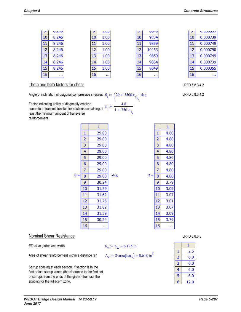
Chapter 5 Concrete Structures
WSDOT Bridge Design Manual M 23-50.17 Page 5-287 June 2017
θi
29 3500 εsi
⋅+
deg⋅:=
βi
4.8
1 750 εsi
⋅+
:=
θ
deg⋅= β
=
bv bw 6.125 in⋅=:=
Av 2 area barv( )⋅ 0.618 in2
⋅=:=
Ph
kip⋅= Vp
kip⋅=
Apsvi
if ts Ytg+ ECi 1,
+h
2≥ Np Ap⋅, Ns Ap⋅,
:=
RFi
fpsi
fpsIi
:=
As 0.0 in
2⋅:=
Muvi
max Mui
Vui
Vpi
− dvi
⋅,
:=
εs
imin max
Muvi
dvi
0.5 Nu⋅+ Vui
Vpi
−+ Apsvi
RFi
⋅ fpo⋅ TRANi
⋅−
Es As⋅ Ep Apsvi
⋅ RFi
⋅+
0,
.006,
:=
εsi
εsrc
SEi
SErc
≤if
εsrows SE( ) rc− 1+
SEi
SErows SE( ) rc− 1+
≥if
εsi
otherwise
:=
Apsv
in2
⋅= RF
= Muv
kip ft⋅⋅= εs
=

Concrete Structures Chapter 5
Page 5-288 WSDOT Bridge Design Manual M 23-50.17 June 2017
si
VR2 2,
return SEi
VR1 1,
≤if
VRrows VR( ) 1− 2,
return SEi
GL VRrows VR( ) 1,
−≥if
VRk 2,
return SEi
1
k
j
VRj 1,
=
≤if
k 1 rows VR( )..∈for
:= s
in⋅=
Vci
0.0316 βi
⋅
f'c
ksi⋅ ksi⋅ bv⋅ dv
i⋅:=
Vs
i
Av fy⋅ dvi
⋅ cot θi( )⋅
si
:=
Vni
min
Vci
Vsi
+ Vpi
+
0.25 f'c⋅ bv⋅ dvi
⋅ Vpi
+
:=
Vc
kip⋅= Vs
kip⋅= Vn
kip⋅= ϕv Vn⋅
kip⋅=
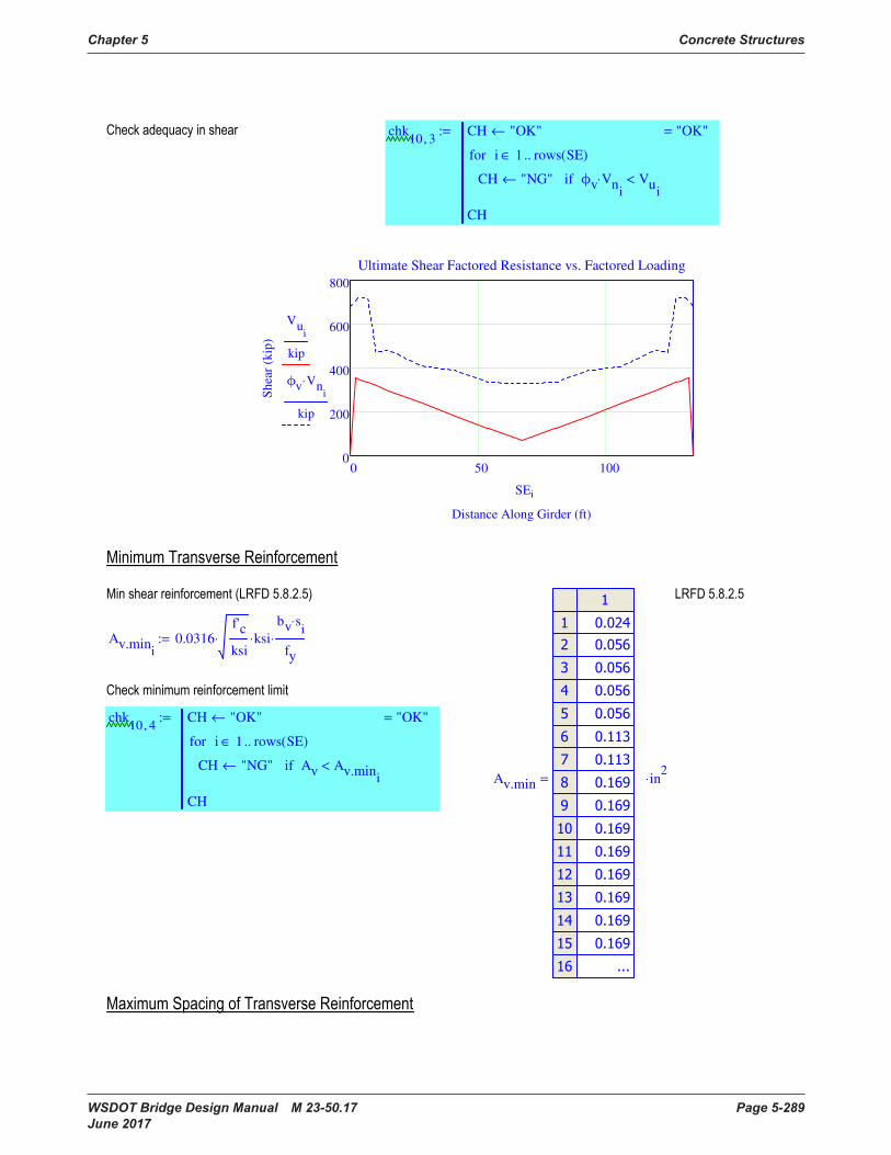
Chapter 5 Concrete Structures
WSDOT Bridge Design Manual M 23-50.17 Page 5-289 June 2017
chk10 3,
CH "OK"←
CH "NG"← ϕv Vni
⋅ Vui
<if
i 1 rows SE( )..∈for
CH
"OK"=:=
0 50 1000
200
400
600
800
Ultimate Shear Factored Resistance vs. Factored Loading
Distance Along Girder (ft)
Sh
ear
(kip
)
Vui
kip
ϕv Vni
⋅
kip
SEi
Av.mini
0.0316f'c
ksi⋅ ksi⋅
bv si
⋅
fy
⋅:=
chk10 4,
CH "OK"←
CH "NG"← Av Av.mini
<if
i 1 rows SE( )..∈for
CH
"OK"=:=
Av.min
in2
⋅=
si
VR2 2,
return SEi
VR1 1,
≤if
VRrows VR( ) 1− 2,
return SEi
GL VRrows VR( ) 1,
−≥if
VRk 2,
return SEi
1
k
j
VRj 1,
=
≤if
k 1 rows VR( )..∈for
:= s
in⋅=
Vci
0.0316 βi
⋅
f'c
ksi⋅ ksi⋅ bv⋅ dv
i⋅:=
Vs
i
Av fy⋅ dvi
⋅ cot θi( )⋅
si
:=
Vni
min
Vci
Vsi
+ Vpi
+
0.25 f'c⋅ bv⋅ dvi
⋅ Vpi
+
:=
Vc
kip⋅= Vs
kip⋅= Vn
kip⋅= ϕv Vn⋅
kip⋅=
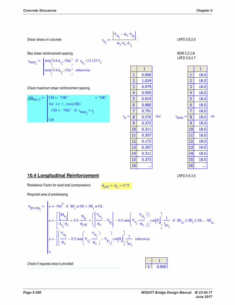
Concrete Structures Chapter 5
Page 5-290 WSDOT Bridge Design Manual M 23-50.17 June 2017
vui
Vui
ϕv Vpi
⋅−
ϕv bv⋅ dvi
⋅
:=
smaxi
min 0.8 dvi
18in,
vui
0.125 f'c⋅<if
min 0.4 dvi
12in,
otherwise
:=
chk10 5,
CH "OK"←
CH "NG"← smaxi
si
<if
i 1 rows SE( )..∈for
CH
"OK"=:=
vu
ksi⋅= smax
in⋅=
10.4 Longitudinal Reinforcement
ϕcN ϕc 0.75=:=
Aps.reqi
a 0in2
← SEi
0ft= SEi
GL=∨if
a
Mui
dviϕ
i⋅
0.5Nu
ϕcN
⋅+
Vui
ϕv
Vpi
− 0.5 min Vsi
Vui
ϕv
,
⋅−
cot θi( )⋅+
1
fpsi
⋅← SErc
SEi
≤ GL SErc
−≤if
a
Vui
ϕv
0.5 min Vsi
Vui
ϕv
,
⋅− Vpi
−
cot θi( )⋅
1
fpsi
⋅← otherwise
a
:=
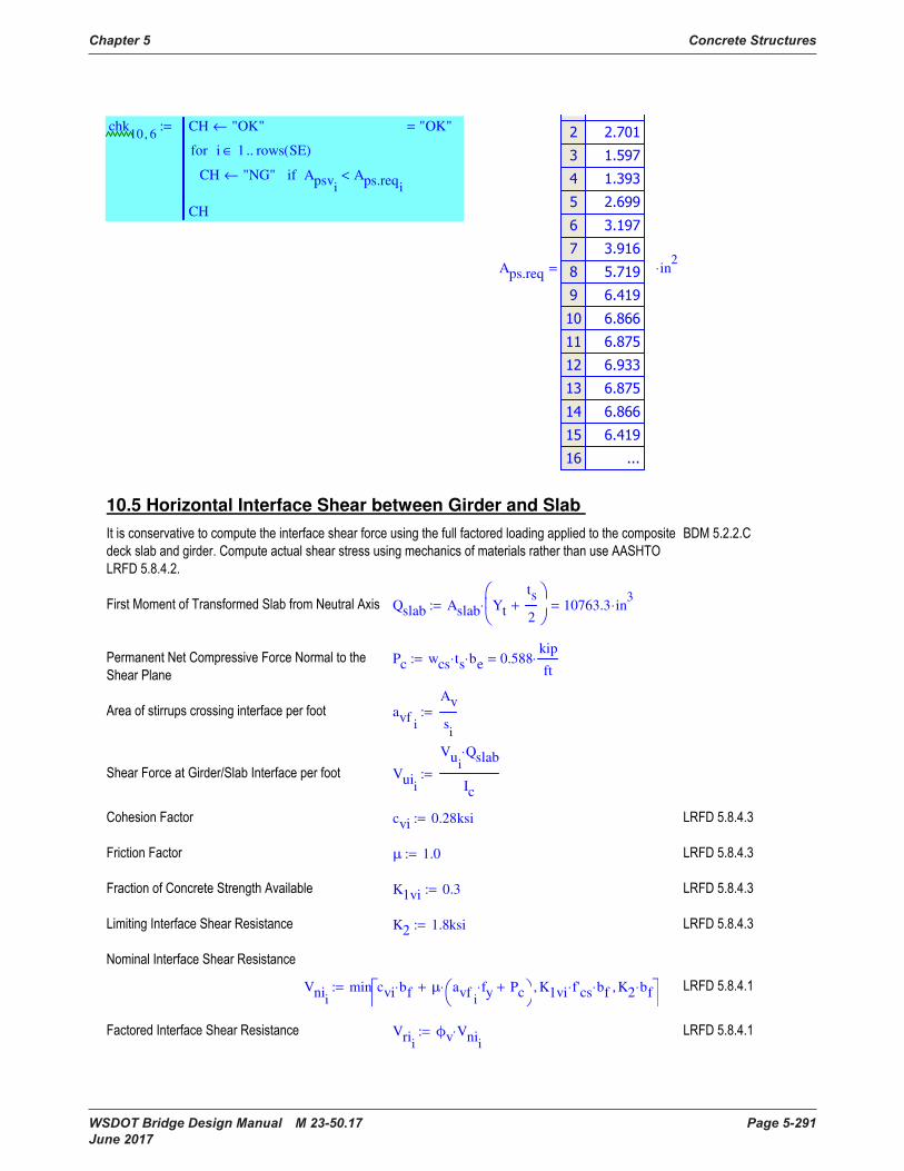
Chapter 5 Concrete Structures
WSDOT Bridge Design Manual M 23-50.17 Page 5-291 June 2017
chk10 6,
CH "OK"←
CH "NG"← Apsvi
Aps.reqi
<if
i 1 rows SE( )..∈for
CH
"OK"=:=
Aps.req
in2
⋅=
10.5 Horizontal Interface Shear between Girder and Slab
Qslab Aslab Yt
ts
2+
⋅ 10763.3 in3
⋅=:=
Pc wcs ts⋅ be⋅ 0.588kip
ft⋅=:=
avfi
Av
si
:=
Vuii
Vui
Qslab⋅
Ic
:=
cvi 0.28ksi:=
μ 1.0:=
K1vi 0.3:=
K2 1.8ksi:=
Vnii
min cvi bf⋅ μ avfi
fy⋅ Pc+
⋅+ K1vi f'cs⋅ bf⋅, K2 bf⋅,
:=
Vrii
ϕv Vnii
⋅:=
vui
Vui
ϕv Vpi
⋅−
ϕv bv⋅ dvi
⋅
:=
smaxi
min 0.8 dvi
18in,
vui
0.125 f'c⋅<if
min 0.4 dvi
12in,
otherwise
:=
chk10 5,
CH "OK"←
CH "NG"← smaxi
si
<if
i 1 rows SE( )..∈for
CH
"OK"=:=
vu
ksi⋅= smax
in⋅=
10.4 Longitudinal Reinforcement
ϕcN ϕc 0.75=:=
Aps.reqi
a 0in2
← SEi
0ft= SEi
GL=∨if
a
Mui
dviϕ
i⋅
0.5Nu
ϕcN
⋅+
Vui
ϕv
Vpi
− 0.5 min Vsi
Vui
ϕv
,
⋅−
cot θi( )⋅+
1
fpsi
⋅← SErc
SEi
≤ GL SErc
−≤if
a
Vui
ϕv
0.5 min Vsi
Vui
ϕv
,
⋅− Vpi
−
cot θi( )⋅
1
fpsi
⋅← otherwise
a
:=
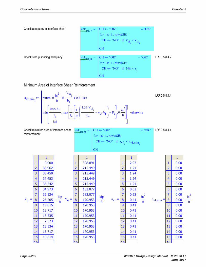
Concrete Structures Chapter 5
Page 5-292 WSDOT Bridge Design Manual M 23-50.17 June 2017
chk10 7,
CH "OK"←
CH "NG"← Vrii
Vuii
<if
i 1 rows SE( )..∈for
CH
"OK"=:=
chk10 8,
CH "OK"←
CH "NG"← 24in si
<if
i 1 rows SE( )..∈for
CH
"OK"=:=
avf.min
i0
in2
ftreturn
Vuii
bf
0.210ksi<if
min0.05 bf⋅
fy
ksi
max1
fy
1
μ
1.33 Vuii
⋅
ϕv
cvi bf⋅−
⋅ Pc−
⋅ 0in
2
ft,
,
otherwise
:=
chk10 9,
CH "OK"←
CH "NG"← avfi
avf.mini
<if
i 1 rows SE( )..∈for
CH
"OK"=:=
Vui
kip
ft⋅= Vri
kip
ft⋅= avf
in2
ft⋅= avf.min
in2
ft⋅=

Chapter 5 Concrete Structures
WSDOT Bridge Design Manual M 23-50.17 Page 5-293 June 2017
10.6 Pretensioned Anchorage Zone
lsplit
dg
418.50 in⋅=:=
As.burst
x i← lsplit
1
i
j
VRj 1,
=
>if
i 1 rows VR( )..∈for
AV AV Av ceil
VRi 1,
VRi 2,
⋅+← i x≤if
AV AV Av floor
lsplit
1
i 1−
j
VRj 1,
=
−
VRi 2,
⋅+← otherwise
i 1 x 1+..∈for
AV
4.326 in2
⋅=:=
fs 20ksi:=
Pr fs As.burst⋅ 86.52 kip⋅=:=
Pr.min 0.04 fpbt⋅ Apstemp⋅ 76.58 kip⋅=:=
chk10 10,
if Pr Pr.min≥ "OK", "NG", ( ) "OK"=:=
lconfine 1.5 dg⋅ 9.250 ft⋅=:=
chk10 7,
CH "OK"←
CH "NG"← Vrii
Vuii
<if
i 1 rows SE( )..∈for
CH
"OK"=:=
chk10 8,
CH "OK"←
CH "NG"← 24in si
<if
i 1 rows SE( )..∈for
CH
"OK"=:=
avf.min
i0
in2
ftreturn
Vuii
bf
0.210ksi<if
min0.05 bf⋅
fy
ksi
max1
fy
1
μ
1.33 Vuii
⋅
ϕv
cvi bf⋅−
⋅ Pc−
⋅ 0in
2
ft,
,
otherwise
:=
chk10 9,
CH "OK"←
CH "NG"← avfi
avf.mini
<if
i 1 rows SE( )..∈for
CH
"OK"=:=
Vui
kip
ft⋅= Vri
kip
ft⋅= avf
in2
ft⋅= avf.min
in2
ft⋅=
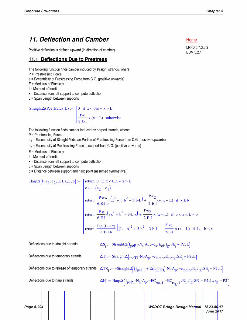
Concrete Structures Chapter 5
Page 5-294 WSDOT Bridge Design Manual M 23-50.17 June 2017
11. Deflection and Camber
11.1 Deflections Due to Prestress
Straight∆ P e, E, I, x, L, ( ) 0 x 0in< x L>∨if
P e⋅
2 E⋅ I⋅x⋅ x L−( )⋅ otherwise
:=
Harp∆ P e1, e2, E, I, x, L, b, ( ) 0return x 0in< x L>∨if
e e2 e1−( )−←
P e⋅ x⋅
6 E⋅ I⋅ b⋅x2
3 b2
⋅+ 3 b⋅ L⋅−( )⋅
P e2⋅
2 E⋅ I⋅x⋅ x L−( )⋅+return x b≤if
P e⋅
6 E⋅ I⋅3x
2b
2+ 3 L⋅ x⋅−( )⋅
P e2⋅
2 E⋅ I⋅x⋅ x L−( )⋅+return b x< L b−<if
P e⋅ L x−( )⋅
6 E⋅ I⋅ b⋅L x−( )
23 b
2⋅+ 3 b⋅ L⋅−
⋅
P e2⋅
2 E⋅ I⋅x⋅ x L−( )⋅+return L b− x≤if
:=
∆Si
Straight∆ fpeP1 Ns⋅ Ap⋅ es−, Eci, Ig, SEi
P2−, L, ( ):=
∆Ti
Straight∆ fpeT1 Nt⋅ Ap⋅ etemp−, Eci, Ig, SEi
P2−, L, ( ):=
∆TRi
Straight∆ fpeT1 ∆fpLTH+( ) Nt⋅ Ap⋅ etemp−, Ec, Ig, SEi
P2−, L, −:=
∆Hi
Harp∆ fpeP1 Nh⋅ Ap⋅ ECrm 1,
−, ECrsL 1,
−, Eci, Ig, SEi
P2−, L, xh P2−,
:=

Chapter 5 Concrete Structures
WSDOT Bridge Design Manual M 23-50.17 Page 5-295 June 2017
∆S
in⋅= ∆T
in⋅= ∆TR
in⋅= ∆H
in⋅=
11.2 Deflections due to Dead Loads
∆POINT P a, x, L, E, I, ( ) 0return x 0in< x L>∨if
0return a 0in< a L>∨if
P L a−( )⋅ x⋅
6 E⋅ I⋅ L⋅L
2L a−( )
2− x
2−
⋅return x a<if
P a2
⋅ L a−( )2
⋅
3 E⋅ I⋅ L⋅return x a=if
P a⋅ L x−( )⋅
6 E⋅ I⋅ L⋅L
2a2
− L x−( )2
− ⋅return otherwise
:=
11. Deflection and Camber
11.1 Deflections Due to Prestress
Straight∆ P e, E, I, x, L, ( ) 0 x 0in< x L>∨if
P e⋅
2 E⋅ I⋅x⋅ x L−( )⋅ otherwise
:=
Harp∆ P e1, e2, E, I, x, L, b, ( ) 0return x 0in< x L>∨if
e e2 e1−( )−←
P e⋅ x⋅
6 E⋅ I⋅ b⋅x2
3 b2
⋅+ 3 b⋅ L⋅−( )⋅
P e2⋅
2 E⋅ I⋅x⋅ x L−( )⋅+return x b≤if
P e⋅
6 E⋅ I⋅3x
2b
2+ 3 L⋅ x⋅−( )⋅
P e2⋅
2 E⋅ I⋅x⋅ x L−( )⋅+return b x< L b−<if
P e⋅ L x−( )⋅
6 E⋅ I⋅ b⋅L x−( )
23 b
2⋅+ 3 b⋅ L⋅−
⋅
P e2⋅
2 E⋅ I⋅x⋅ x L−( )⋅+return L b− x≤if
:=
∆Si
Straight∆ fpeP1 Ns⋅ Ap⋅ es−, Eci, Ig, SEi
P2−, L, ( ):=
∆Ti
Straight∆ fpeT1 Nt⋅ Ap⋅ etemp−, Eci, Ig, SEi
P2−, L, ( ):=
∆TRi
Straight∆ fpeT1 ∆fpLTH+( ) Nt⋅ Ap⋅ etemp−, Ec, Ig, SEi
P2−, L, −:=
∆Hi
Harp∆ fpeP1 Nh⋅ Ap⋅ ECrm 1,
−, ECrsL 1,
−, Eci, Ig, SEi
P2−, L, xh P2−,
:=
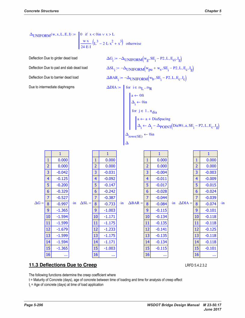
Concrete Structures Chapter 5
Page 5-296 WSDOT Bridge Design Manual M 23-50.17 June 2017
∆UNIFORM w x, L, E, I, ( ) 0 x 0in< x L>∨if
w x⋅
24 E⋅ I⋅L
32 L⋅ x
2⋅− x
3+( )⋅ otherwise
:=
∆Gi
∆UNIFORM wg SEi
P2−, L, Eci, Ig, ( )−:=
∆SLi
∆UNIFORM wpu ws+ SEi
P2−, L, Ec, Ig, ( )−:=
∆BARi
∆UNIFORM wb SEi
P2−, L, Ec, Ic, ( )−:=
∆DIA
a 0ft←
∆i
0in←
a a DiaSpacing+←
∆i
∆i
∆POINT DiaWt a, SEi
P2−, L, Ec, Ig, ( )−←
j 1 ndia..∈for
i rsL rsR..∈for
∆rows SE( )
0in←
∆
:=
∆G
in⋅= ∆SL
in⋅= ∆BAR
in⋅= ∆DIA
in⋅=
11.3 Deflections Due to Creep
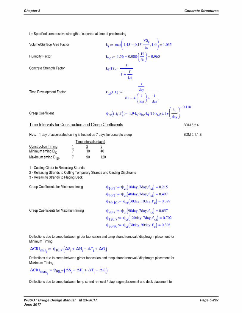
Chapter 5 Concrete Structures
WSDOT Bridge Design Manual M 23-50.17 Page 5-297 June 2017
ks max 1.45 0.13VSr
in⋅− 1.0,
1.035=:=
khc 1.56 0.008H
%
⋅− 0.960=:=
kf f( )5
1f
ksi+
:=
ktd t f, ( )
t
day
61 4f
ksi
⋅−t
day+
:=
ψcr t ti, f, ( ) 1.9 ks⋅ khc⋅ kf f( )⋅ ktd t f, ( )⋅
ti
day
0.118−
⋅:=
ψ10.7 ψcr 10day 7day, f'ci, ( ) 0.215=:=
ψ40.7 ψcr 40day 7day, f'ci, ( ) 0.497=:=
ψ30.10 ψcr 30day 10day, f'c, ( ) 0.399=:=
ψ90.7 ψcr 90day 7day, f'ci, ( ) 0.657=:=
ψ120.7 ψcr 120day 7day, f'ci, ( ) 0.702=:=
ψ30.90 ψcr 30day 90day, f'c, ( ) 0.308=:=
∆CR1mini
ψ10.7 ∆Si
∆Hi
+ ∆Ti
+ ∆Gi
+( )⋅:=
∆CR1maxi
ψ90.7 ∆Si
∆Hi
+ ∆Ti
+ ∆Gi
+( )⋅:=
∆UNIFORM w x, L, E, I, ( ) 0 x 0in< x L>∨if
w x⋅
24 E⋅ I⋅L
32 L⋅ x
2⋅− x
3+( )⋅ otherwise
:=
∆Gi
∆UNIFORM wg SEi
P2−, L, Eci, Ig, ( )−:=
∆SLi
∆UNIFORM wpu ws+ SEi
P2−, L, Ec, Ig, ( )−:=
∆BARi
∆UNIFORM wb SEi
P2−, L, Ec, Ic, ( )−:=
∆DIA
a 0ft←
∆i
0in←
a a DiaSpacing+←
∆i
∆i
∆POINT DiaWt a, SEi
P2−, L, Ec, Ig, ( )−←
j 1 ndia..∈for
i rsL rsR..∈for
∆rows SE( )
0in←
∆
:=
∆G
in⋅= ∆SL
in⋅= ∆BAR
in⋅= ∆DIA
in⋅=
11.3 Deflections Due to Creep
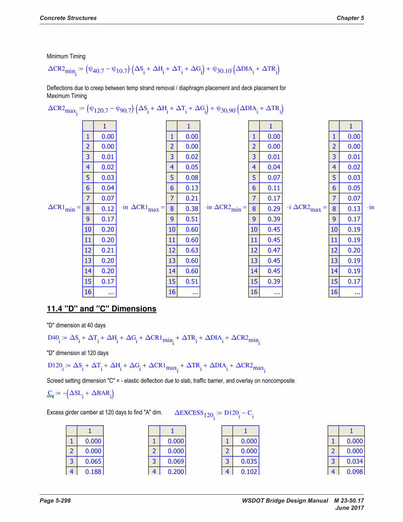
Concrete Structures Chapter 5
Page 5-298 WSDOT Bridge Design Manual M 23-50.17 June 2017
∆CR2mini
ψ40.7 ψ10.7−( ) ∆Si
∆Hi
+ ∆Ti
+ ∆Gi
+( )⋅ ψ30.10 ∆DIAi
∆TRi
+( )⋅+:=
∆CR2maxi
ψ120.7 ψ90.7−( ) ∆Si
∆Hi
+ ∆Ti
+ ∆Gi
+( )⋅ ψ30.90 ∆DIAi
∆TRi
+( )⋅+:=
∆CR1min
in⋅= ∆CR1max
in⋅= ∆CR2min
in⋅= ∆CR2max
in⋅=
11.4 "D" and "C" Dimensions
D40i
∆Si
∆Ti
+ ∆Hi
+ ∆Gi
+ ∆CR1mini
+ ∆TRi
+ ∆DIAi
+ ∆CR2mini
+:=
D120i
∆Si
∆Ti
+ ∆Hi
+ ∆Gi
+ ∆CR1maxi
+ ∆TRi
+ ∆DIAi
+ ∆CR2maxi
+:=
Ci
∆SLi
∆BARi
+( )−:=
∆EXCESS120i
D120i
Ci
−:=

Chapter 5 Concrete Structures
WSDOT Bridge Design Manual M 23-50.17 Page 5-299 June 2017
D40
in⋅= D120
in⋅= C
in⋅= ∆EXCESS120
in⋅=
0.5 D40rm
⋅ 1.067 in⋅=
D120rm
2.282 in⋅=
Crm
1.375 in⋅=
chk11 1,
if ∆EXCESS120rm
AEx≤ "OK", "NG",
"OK"=:=
11.5 Deflections Due to Live Load
∆LL.limL
8001.950 in⋅=:=
bslab.trans BW 2 cw⋅+( ) n⋅ 311.51 in⋅=:=
Islab2 bslab.trans ts3
⋅ 12÷ 8904.1 in4
⋅=:=
Aslab2 bslab.trans ts⋅ 2180.6 in2
⋅=:=
Ybs 77.500 in⋅=
∆CR2mini
ψ40.7 ψ10.7−( ) ∆Si
∆Hi
+ ∆Ti
+ ∆Gi
+( )⋅ ψ30.10 ∆DIAi
∆TRi
+( )⋅+:=
∆CR2maxi
ψ120.7 ψ90.7−( ) ∆Si
∆Hi
+ ∆Ti
+ ∆Gi
+( )⋅ ψ30.90 ∆DIAi
∆TRi
+( )⋅+:=
∆CR1min
in⋅= ∆CR1max
in⋅= ∆CR2min
in⋅= ∆CR2max
in⋅=
11.4 "D" and "C" Dimensions
D40i
∆Si
∆Ti
+ ∆Hi
+ ∆Gi
+ ∆CR1mini
+ ∆TRi
+ ∆DIAi
+ ∆CR2mini
+:=
D120i
∆Si
∆Ti
+ ∆Hi
+ ∆Gi
+ ∆CR1maxi
+ ∆TRi
+ ∆DIAi
+ ∆CR2maxi
+:=
Ci
∆SLi
∆BARi
+( )−:=
∆EXCESS120i
D120i
Ci
−:=

Concrete Structures Chapter 5
Page 5-300 WSDOT Bridge Design Manual M 23-50.17 June 2017
Yb2
Aslab2 Ybs⋅ Nb Ag⋅ Ybg⋅+
Aslab2 Nb Ag⋅+
47.48 in⋅=:=
Yt2 dg Yb2− 26.52 in⋅=:=
Yts2 ts Yt2+ 33.52 in⋅=:=
Islabc2 Aslab2 Yts2 0.5ts−( )2
⋅ Islab2+ 1974622 in4
⋅=:=
Igc2 Nb Ag⋅ Yb2 Ybg−( )2
⋅ Nb Ig⋅+ 5179723 in4
⋅=:=
Ic2 Islabc2 Igc2+ 7154345 in4
⋅=:=
HL93Truck∆ x L, ( ) Axles
8kip
32kip
32kip
←
Locations
0ft
14− ft
28− ft
←
rows rows Locations( )←
Loc Locations←
Deflection 0in←
∆i
∆POINT Axlesi
Loci
, x, L, Ec, Ic2, ( )←
Loci
Loci
0.01ft+←
i 1 rows..∈for
Deflection max ∆ Deflection,
←
Locrows
L≤while
Loc Locations←
x L x−←
∆i
∆POINT Axlesi
Loci
, x, L, Ec, Ic2, ( )←
Loci
Loci
0.01ft+←
i 1 rows..∈for
Deflection max ∆ Deflection,
←
Locrows
L≤while
Deflection
:=
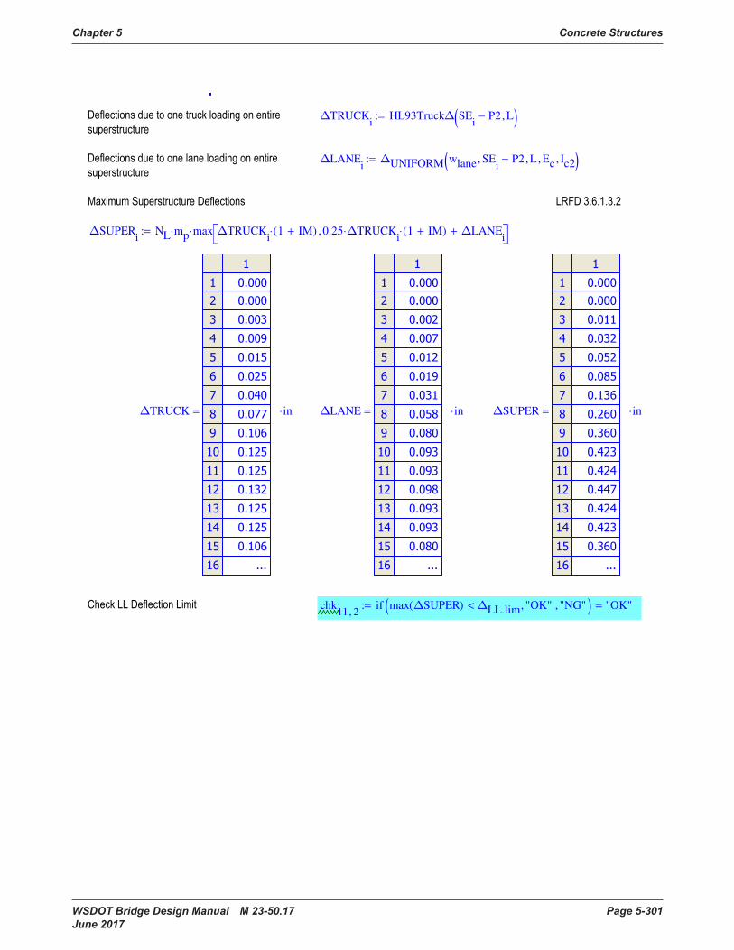
Chapter 5 Concrete Structures
WSDOT Bridge Design Manual M 23-50.17 Page 5-301 June 2017
Deflection
∆TRUCKi
HL93Truck∆ SEi
P2− L, ( ):=
∆LANEi
∆UNIFORM wlane SEi
P2−, L, Ec, Ic2, ( ):=
∆SUPERi
NL mp⋅ max ∆TRUCKi
1 IM+( )⋅ 0.25 ∆TRUCKi
⋅ 1 IM+( )⋅ ∆LANEi
+, ⋅:=
∆TRUCK
in⋅= ∆LANE
in⋅= ∆SUPER
in⋅=
chk11 2,
if max ∆SUPER( ) ∆LL.lim< "OK", "NG", ( ) "OK"=:=
Yb2
Aslab2 Ybs⋅ Nb Ag⋅ Ybg⋅+
Aslab2 Nb Ag⋅+
47.48 in⋅=:=
Yt2 dg Yb2− 26.52 in⋅=:=
Yts2 ts Yt2+ 33.52 in⋅=:=
Islabc2 Aslab2 Yts2 0.5ts−( )2
⋅ Islab2+ 1974622 in4
⋅=:=
Igc2 Nb Ag⋅ Yb2 Ybg−( )2
⋅ Nb Ig⋅+ 5179723 in4
⋅=:=
Ic2 Islabc2 Igc2+ 7154345 in4
⋅=:=
HL93Truck∆ x L, ( ) Axles
8kip
32kip
32kip
←
Locations
0ft
14− ft
28− ft
←
rows rows Locations( )←
Loc Locations←
Deflection 0in←
∆i
∆POINT Axlesi
Loci
, x, L, Ec, Ic2, ( )←
Loci
Loci
0.01ft+←
i 1 rows..∈for
Deflection max ∆ Deflection,
←
Locrows
L≤while
Loc Locations←
x L x−←
∆i
∆POINT Axlesi
Loci
, x, L, Ec, Ic2, ( )←
Loci
Loci
0.01ft+←
i 1 rows..∈for
Deflection max ∆ Deflection,
←
Locrows
L≤while
Deflection
:=
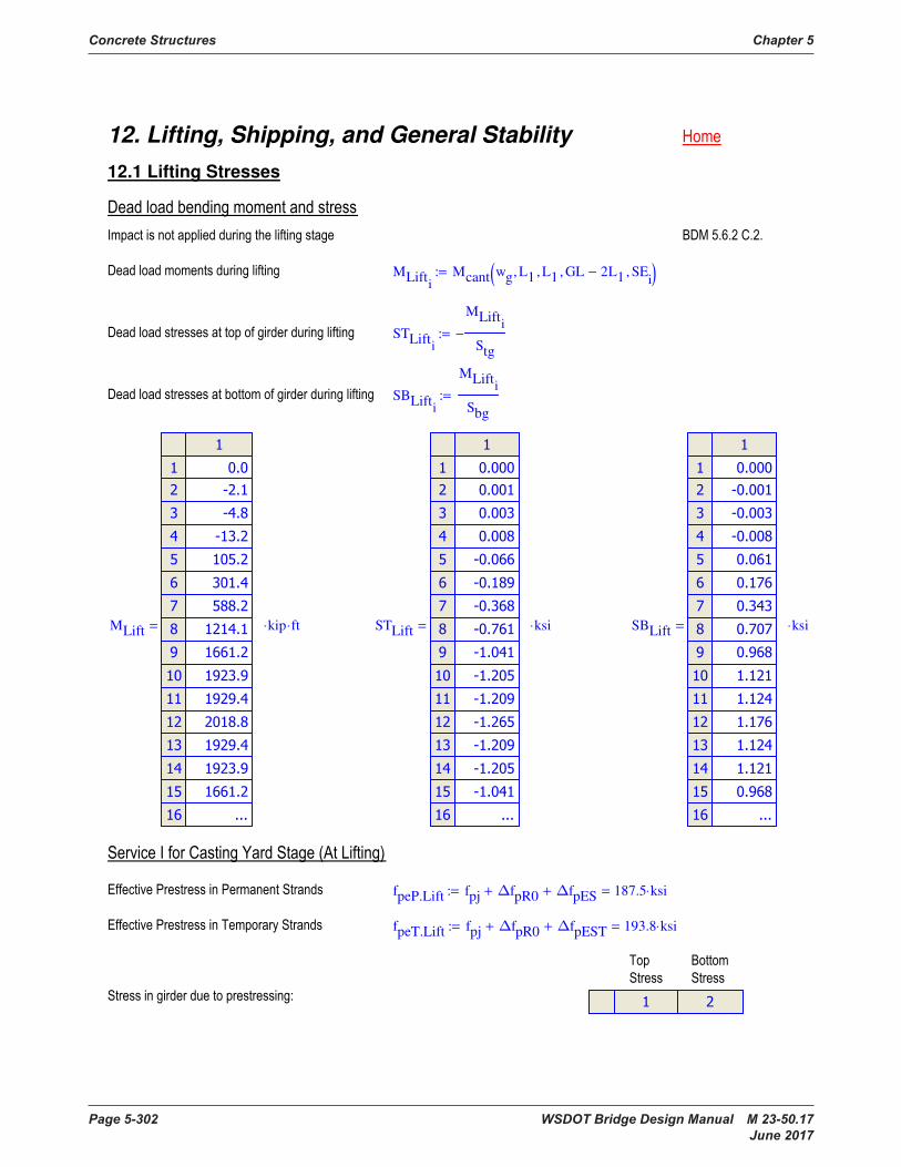
Concrete Structures Chapter 5
Page 5-302 WSDOT Bridge Design Manual M 23-50.17 June 2017
12. Lifting, Shipping, and General Stability
12.1 Lifting Stresses
MLifti
Mcant wg L1, L1, GL 2L1−, SEi
, ( ):=
STLifti
MLifti
Stg
−:=
SBLifti
MLifti
Sbg
:=
MLift
kip ft⋅⋅= STLift
ksi⋅= SBLift
ksi⋅=
fpeP.Lift fpj ∆fpR0+ ∆fpES+ 187.5 ksi⋅=:=
fpeT.Lift fpj ∆fpR0+ ∆fpEST+ 193.8 ksi⋅=:=

Chapter 5 Concrete Structures
WSDOT Bridge Design Manual M 23-50.17 Page 5-303 June 2017
PSLift
Pp fpeP.Lift TRANi
⋅ Aps⋅←
Pt fpeT.Lift TRANi
⋅ Atemp⋅←
PSi 1,
Pp
Ag
Pp ECi 2,
⋅
Stg
−
Pt
Ag
+
Pt etemp⋅
Stg
−
−←
PSi 2,
Pp
Ag
Pp ECi 2,
⋅
Sbg
+
Pt
Ag
+
Pt etemp⋅
Sbg
+
−←
i 1 rows SE( )..∈for
PS
:=
PSLift
ksi⋅=
STRESSLift
STRi 1,
PSLifti 1,
STLifti
+←
STRi 2,
PSLifti 2,
SBLifti
+←
i 1 rows SE( )..∈for
STR
:=
STRESSLift
ksi⋅=
fc.TL.lim 4.875− ksi⋅=
ft.TL.lim 0.520 ksi⋅=
chk12 1,
if min STRESSLift( ) fc.TL.lim≥ "OK", "NG", ( ) "OK"=:=
12. Lifting, Shipping, and General Stability
12.1 Lifting Stresses
MLifti
Mcant wg L1, L1, GL 2L1−, SEi
, ( ):=
STLifti
MLifti
Stg
−:=
SBLifti
MLifti
Sbg
:=
MLift
kip ft⋅⋅= STLift
ksi⋅= SBLift
ksi⋅=
fpeP.Lift fpj ∆fpR0+ ∆fpES+ 187.5 ksi⋅=:=
fpeT.Lift fpj ∆fpR0+ ∆fpEST+ 193.8 ksi⋅=:=
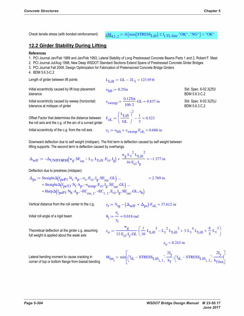
Concrete Structures Chapter 5
Page 5-304 WSDOT Bridge Design Manual M 23-50.17 June 2017
chk12 2,
if max STRESSLift( ) ft.TL.lim≤ "OK", "NG", ( ) "OK"=:=
12.2 Girder Stability During Lifting
LLift GL 2L1− 123.95 ft=:=
elift 0.25in:=
esweep0.125in
10ft 2⋅GL⋅ 0.837 in⋅=:=
FoL
LLift
GL
21
3− 0.523=:=
ei elift esweep FoL⋅+ 0.688 in⋅=:=
∆self ∆UNIFORM wg SErm
L1−, LLift, Eci, Ig, ( )−
wg L12
⋅ LLift2
⋅
16 Eci⋅ Ig⋅
+ 1.377− in⋅=:=
∆ps Straight∆ fpeP1 Ns⋅ Ap⋅ es−, Eci, Ig, SErm
, GL, ( )Straight∆ fpeT1 Nt⋅ Ap⋅ etemp−, Eci, Ig, SE
rm, GL, ( )+
...
Harp∆ fpeP1 Nh⋅ Ap⋅ ECrm 1,
−, EC1 1,
−, Eci, Ig, SErm
, GL, xh, ( )+
...
2.769 in⋅=:=
yr Ytg ∆self ∆ps+( ) FoL⋅− 37.612 in⋅=:=
θi
ei
yr
0.018 rad⋅=:=
zo
wg
12 Eci⋅ Iy⋅ GL⋅
1
10LLift
5⋅ L1
2LLift
3⋅− 3 L1
4⋅ LLift⋅+
6
5L1
5⋅+
⋅:=
zo 8.243 in⋅=
Mlati
min frL STRESSLifti 1,
−
2Iy
bf
⋅ frL STRESSLifti 2,
−
2Iy
bf.bot
⋅,
:=
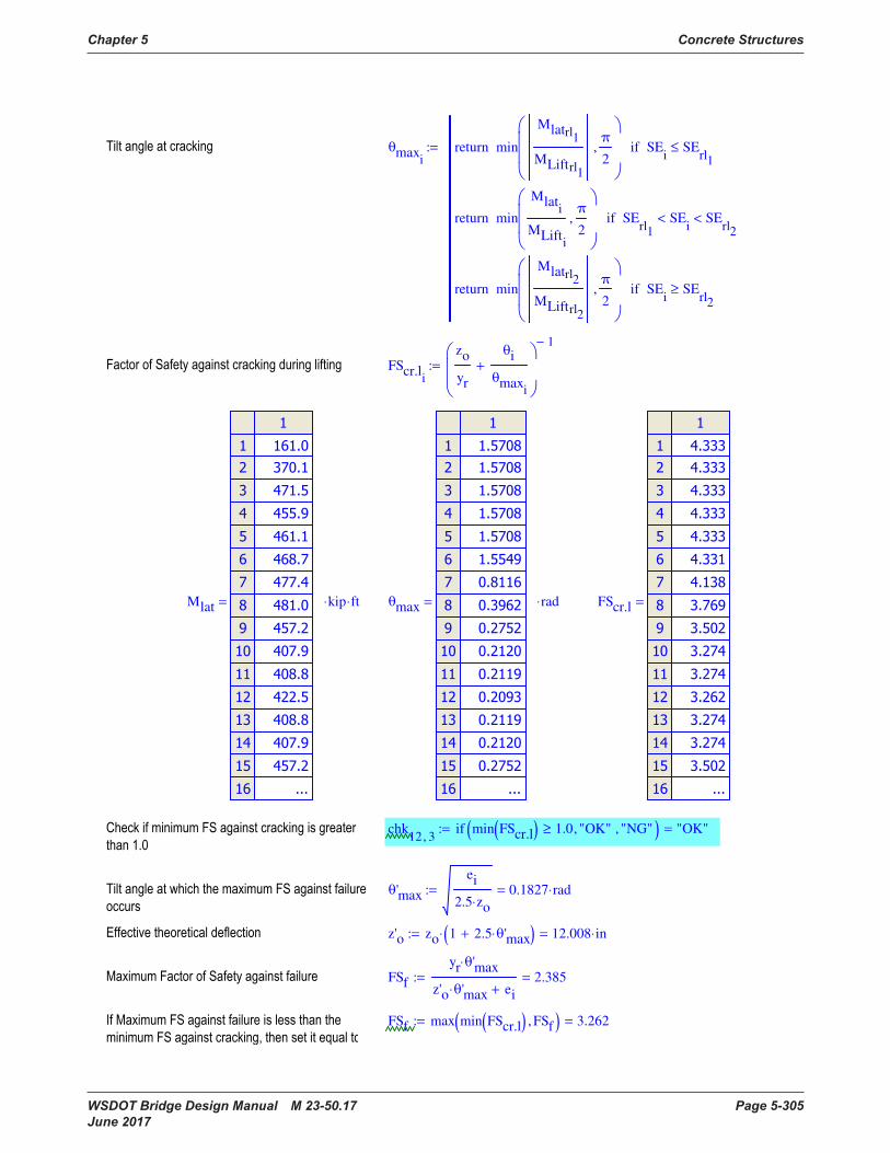
Chapter 5 Concrete Structures
WSDOT Bridge Design Manual M 23-50.17 Page 5-305 June 2017
θmaxi
min
Mlatrl1
MLiftrl1
π
2,
return SEi
SErl1
≤if
min
Mlati
MLifti
π
2,
return SErl1
SEi
< SErl2
<if
min
Mlatrl2
MLiftrl2
π
2,
return SEi
SErl2
≥if
:=
FScr.li
zo
yr
θi
θmaxi
+
1−
:=
Mlat
kip ft⋅⋅= θmax
rad⋅= FScr.l
=
chk12 3,
if min FScr.l( ) 1.0≥ "OK", "NG", ( ) "OK"=:=
θ'max
ei
2.5 zo⋅
0.1827 rad⋅=:=
z'o zo 1 2.5 θ'max⋅+( )⋅ 12.008 in⋅=:=
FSf
yr θ'max⋅
z'o θ'max⋅ ei+
2.385=:=
FSf max min FScr.l( ) FSf, ( ) 3.262=:=
chk12 2,
if max STRESSLift( ) ft.TL.lim≤ "OK", "NG", ( ) "OK"=:=
12.2 Girder Stability During Lifting
LLift GL 2L1− 123.95 ft=:=
elift 0.25in:=
esweep0.125in
10ft 2⋅GL⋅ 0.837 in⋅=:=
FoL
LLift
GL
21
3− 0.523=:=
ei elift esweep FoL⋅+ 0.688 in⋅=:=
∆self ∆UNIFORM wg SErm
L1−, LLift, Eci, Ig, ( )−
wg L12
⋅ LLift2
⋅
16 Eci⋅ Ig⋅
+ 1.377− in⋅=:=
∆ps Straight∆ fpeP1 Ns⋅ Ap⋅ es−, Eci, Ig, SErm
, GL, ( )Straight∆ fpeT1 Nt⋅ Ap⋅ etemp−, Eci, Ig, SE
rm, GL, ( )+
...
Harp∆ fpeP1 Nh⋅ Ap⋅ ECrm 1,
−, EC1 1,
−, Eci, Ig, SErm
, GL, xh, ( )+
...
2.769 in⋅=:=
yr Ytg ∆self ∆ps+( ) FoL⋅− 37.612 in⋅=:=
θi
ei
yr
0.018 rad⋅=:=
zo
wg
12 Eci⋅ Iy⋅ GL⋅
1
10LLift
5⋅ L1
2LLift
3⋅− 3 L1
4⋅ LLift⋅+
6
5L1
5⋅+
⋅:=
zo 8.243 in⋅=
Mlati
min frL STRESSLifti 1,
−
2Iy
bf
⋅ frL STRESSLifti 2,
−
2Iy
bf.bot
⋅,
:=
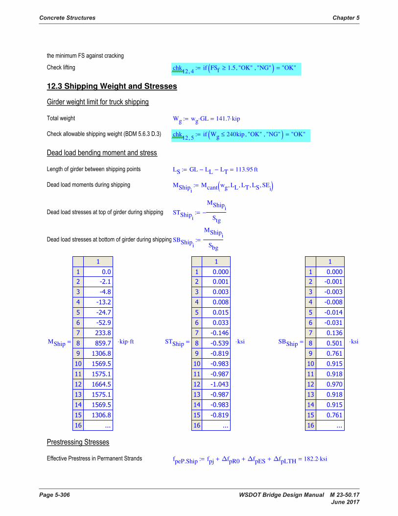
Concrete Structures Chapter 5
Page 5-306 WSDOT Bridge Design Manual M 23-50.17 June 2017
chk12 4,
if FSf 1.5≥ "OK", "NG", ( ) "OK"=:=
12.3 Shipping Weight and Stresses
Wg wg GL⋅ 141.7 kip⋅=:=
chk12 5,
if Wg 240kip≤ "OK", "NG", ( ) "OK"=:=
LS GL LL− LT− 113.95 ft=:=
MShipi
Mcant wg LL, LT, LS, SEi
, ( ):=
STShipi
MShipi
Stg
−:=
SBShipi
MShipi
Sbg
:=
MShip
kip ft⋅⋅= STShip
ksi⋅= SBShip
ksi⋅=
fpeP.Ship fpj ∆fpR0+ ∆fpES+ ∆fpLTH+ 182.2 ksi⋅=:=
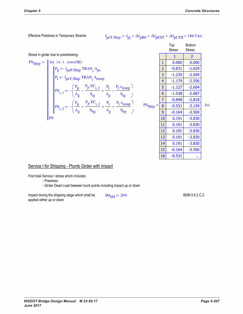
Chapter 5 Concrete Structures
WSDOT Bridge Design Manual M 23-50.17 Page 5-307 June 2017
fpeT.Ship fpj ∆fpR0+ ∆fpEST+ ∆fpLTH+ 188.5 ksi⋅=:=
PSShip
Pp fpeP.Ship TRANi
⋅ Aps⋅←
Pt fpeT.Ship TRANi
⋅ Atemp⋅←
PSi 1,
Pp
Ag
Pp ECi 2,
⋅
Stg
−
Pt
Ag
+
Pt etemp⋅
Stg
−
−←
PSi 2,
Pp
Ag
Pp ECi 2,
⋅
Sbg
+
Pt
Ag
+
Pt etemp⋅
Sbg
+
−←
i 1 rows SE( )..∈for
PS
:=
PSShip
ksi⋅=
IMSH 20%:=
chk12 4,
if FSf 1.5≥ "OK", "NG", ( ) "OK"=:=
12.3 Shipping Weight and Stresses
Wg wg GL⋅ 141.7 kip⋅=:=
chk12 5,
if Wg 240kip≤ "OK", "NG", ( ) "OK"=:=
LS GL LL− LT− 113.95 ft=:=
MShipi
Mcant wg LL, LT, LS, SEi
, ( ):=
STShipi
MShipi
Stg
−:=
SBShipi
MShipi
Sbg
:=
MShip
kip ft⋅⋅= STShip
ksi⋅= SBShip
ksi⋅=
fpeP.Ship fpj ∆fpR0+ ∆fpES+ ∆fpLTH+ 182.2 ksi⋅=:=
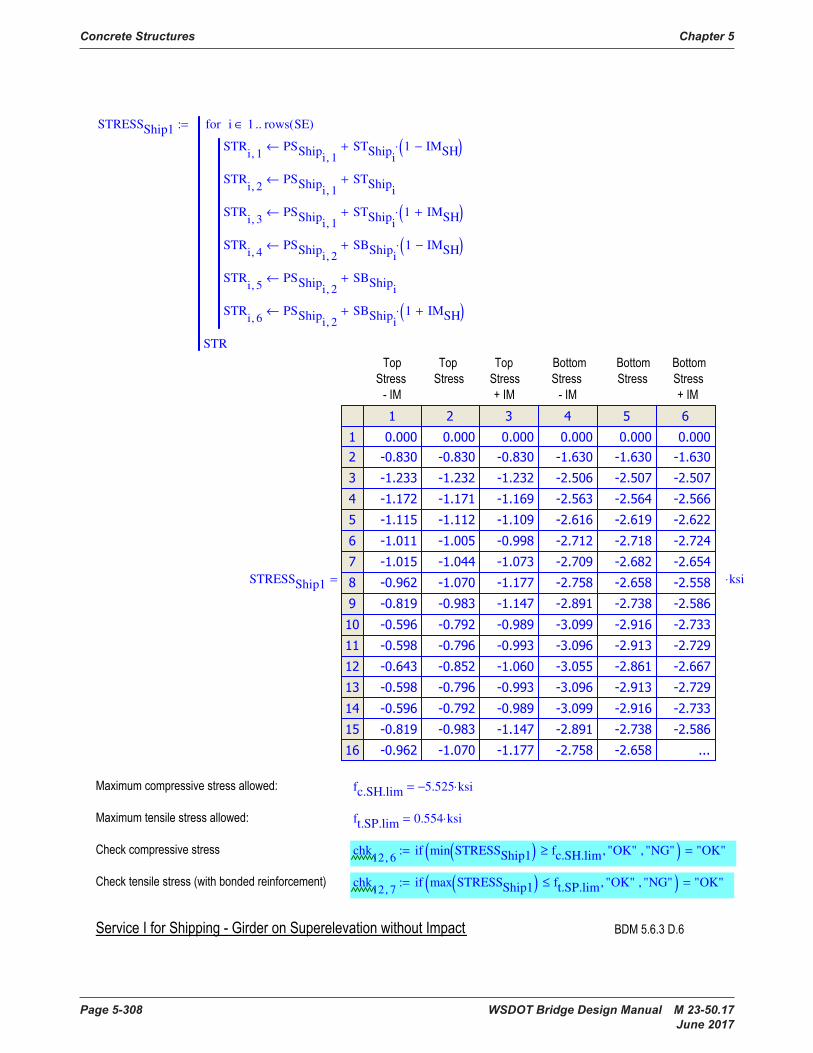
Concrete Structures Chapter 5
Page 5-308 WSDOT Bridge Design Manual M 23-50.17 June 2017
STRESSShip1
STRi 1,
PSShipi 1,
STShipi
1 IMSH−( )⋅+←
STRi 2,
PSShipi 1,
STShipi
+←
STRi 3,
PSShipi 1,
STShipi
1 IMSH+( )⋅+←
STRi 4,
PSShipi 2,
SBShipi
1 IMSH−( )⋅+←
STRi 5,
PSShipi 2,
SBShipi
+←
STRi 6,
PSShipi 2,
SBShipi
1 IMSH+( )⋅+←
i 1 rows SE( )..∈for
STR
:=
STRESSShip1
ksi⋅=
fc.SH.lim 5.525− ksi⋅=
ft.SP.lim 0.554 ksi⋅=
chk12 6,
if min STRESSShip1( ) fc.SH.lim≥ "OK", "NG", ( ) "OK"=:=
chk12 7,
if max STRESSShip1( ) ft.SP.lim≤ "OK", "NG", ( ) "OK"=:=
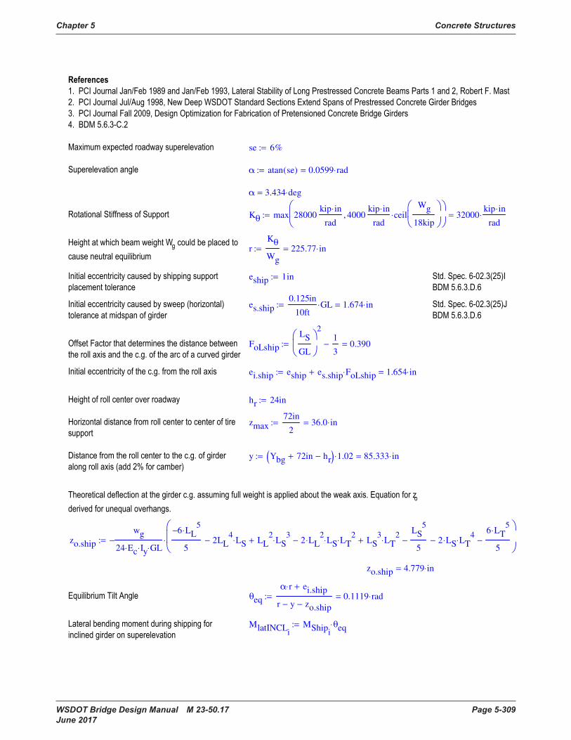
Chapter 5 Concrete Structures
WSDOT Bridge Design Manual M 23-50.17 Page 5-309 June 2017
se 6%:=
α atan se( ) 0.0599 rad⋅=:=
α 3.434 deg⋅=
Kθ max 28000kip in⋅
rad4000
kip in⋅
radceil
Wg
18kip
⋅,
32000kip in⋅
rad⋅=:=
rKθ
Wg
225.77 in⋅=:=
eship 1in:=
es.ship0.125in
10ftGL⋅ 1.674 in⋅=:=
FoLship
LS
GL
21
3− 0.390=:=
ei.ship eship es.ship FoLship⋅+ 1.654 in⋅=:=
hr 24in:=
zmax72in
236.0 in⋅=:=
y Ybg 72in+ hr−( ) 1.02⋅ 85.333 in⋅=:=
zo.ship
wg
24 Ec⋅ Iy⋅ GL⋅
−
6− LL5
⋅
52LL
4LS⋅− LL
2LS
3⋅+ 2 LL
2⋅ LS⋅ LT
2⋅− LS
3LT
2⋅+
LS5
5− 2 LS⋅ LT
4⋅−
6 LT5
⋅
5−
⋅:=
zo.ship 4.779 in⋅=
θeq
α r⋅ ei.ship+
r y− zo.ship−
0.1119 rad⋅=:=
MlatINCLi
MShipiθeq⋅:=
STRESSShip1
STRi 1,
PSShipi 1,
STShipi
1 IMSH−( )⋅+←
STRi 2,
PSShipi 1,
STShipi
+←
STRi 3,
PSShipi 1,
STShipi
1 IMSH+( )⋅+←
STRi 4,
PSShipi 2,
SBShipi
1 IMSH−( )⋅+←
STRi 5,
PSShipi 2,
SBShipi
+←
STRi 6,
PSShipi 2,
SBShipi
1 IMSH+( )⋅+←
i 1 rows SE( )..∈for
STR
:=
STRESSShip1
ksi⋅=
fc.SH.lim 5.525− ksi⋅=
ft.SP.lim 0.554 ksi⋅=
chk12 6,
if min STRESSShip1( ) fc.SH.lim≥ "OK", "NG", ( ) "OK"=:=
chk12 7,
if max STRESSShip1( ) ft.SP.lim≤ "OK", "NG", ( ) "OK"=:=
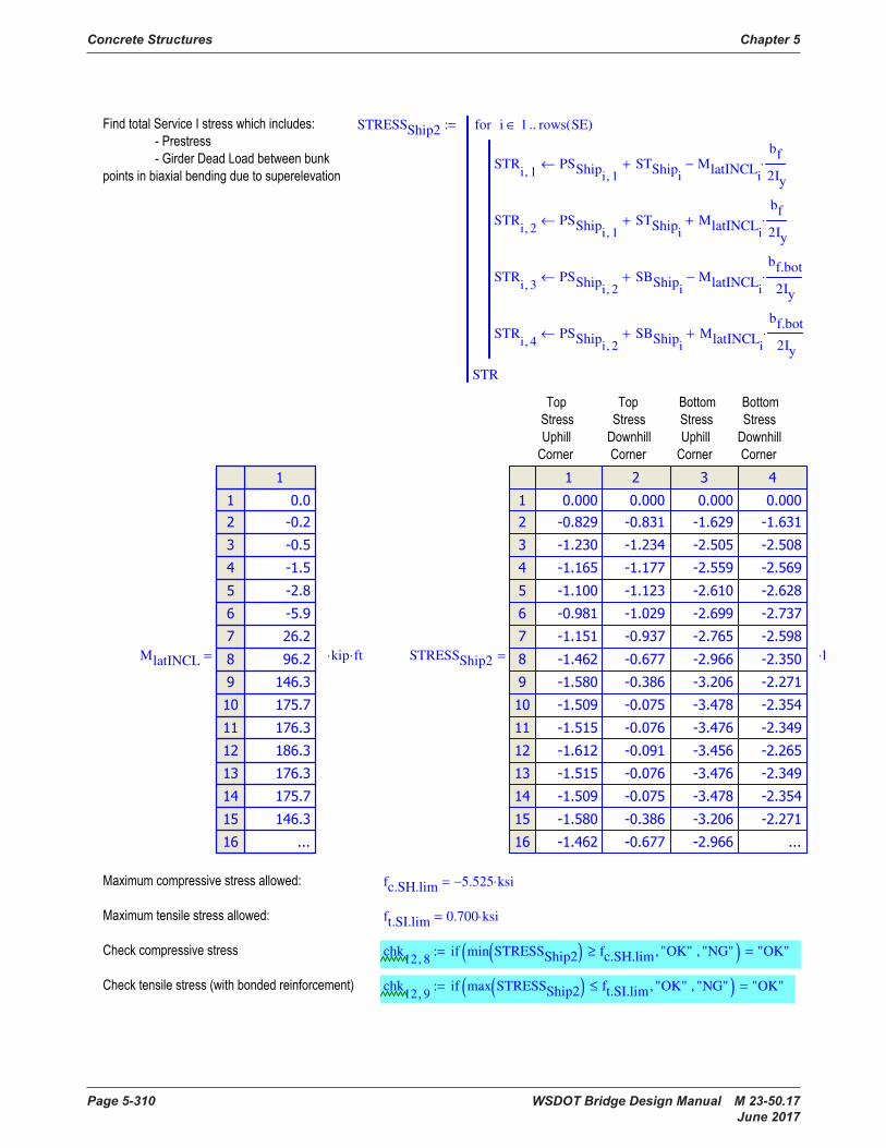
Concrete Structures Chapter 5
Page 5-310 WSDOT Bridge Design Manual M 23-50.17 June 2017
STRESSShip2
STRi 1,
PSShipi 1,
STShipi
+ MlatINCLi
bf
2Iy
⋅−←
STRi 2,
PSShipi 1,
STShipi
+ MlatINCLi
bf
2Iy
⋅+←
STRi 3,
PSShipi 2,
SBShipi
+ MlatINCLi
bf.bot
2Iy
⋅−←
STRi 4,
PSShipi 2,
SBShipi
+ MlatINCLi
bf.bot
2Iy
⋅+←
i 1 rows SE( )..∈for
STR
:=
MlatINCL
kip ft⋅⋅= STRESSShip2
ksi⋅=
fc.SH.lim 5.525− ksi⋅=
ft.SI.lim 0.700 ksi⋅=
chk12 8,
if min STRESSShip2( ) fc.SH.lim≥ "OK", "NG", ( ) "OK"=:=
chk12 9,
if max STRESSShip2( ) ft.SI.lim≤ "OK", "NG", ( ) "OK"=:=
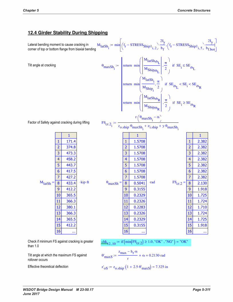
Chapter 5 Concrete Structures
WSDOT Bridge Design Manual M 23-50.17 Page 5-311 June 2017
12.4 Girder Stability During Shipping
MlatShi
min fr STRESSShip1i 2,
−
2Iy
bf
⋅ fr STRESSShip1i 5,
−
2Iy
bf.bot
⋅,
:=
θmaxShi
min
MlatShrbL
MShiprbL
π
2,
return SEi
SErbL
≤if
min
MlatShi
MShipi
π
2,
return SErbL
SEi
< SErbR
<if
min
MlatShrbR
MShiprbR
π
2,
return SEi
SErbR
≥if
:=
FScr.2i
r θmaxShi
α−
⋅
zo.ship θmaxShi
⋅ ei.ship+ y θmaxShi
⋅+
:=
MlatSh
kip ft⋅⋅= θmaxSh
rad⋅= FScr.2
=
chk12 10,
if min FScr.2( ) 1.0≥ "OK", "NG", ( ) "OK"=:=
θ'maxS
zmax hr α⋅−
rα+ 0.2130 rad⋅=:=
z'oS zo.ship 1 2.5 θ'maxS⋅+( )⋅ 7.325 in⋅=:=
STRESSShip2
STRi 1,
PSShipi 1,
STShipi
+ MlatINCLi
bf
2Iy
⋅−←
STRi 2,
PSShipi 1,
STShipi
+ MlatINCLi
bf
2Iy
⋅+←
STRi 3,
PSShipi 2,
SBShipi
+ MlatINCLi
bf.bot
2Iy
⋅−←
STRi 4,
PSShipi 2,
SBShipi
+ MlatINCLi
bf.bot
2Iy
⋅+←
i 1 rows SE( )..∈for
STR
:=
MlatINCL
kip ft⋅⋅= STRESSShip2
ksi⋅=
fc.SH.lim 5.525− ksi⋅=
ft.SI.lim 0.700 ksi⋅=
chk12 8,
if min STRESSShip2( ) fc.SH.lim≥ "OK", "NG", ( ) "OK"=:=
chk12 9,
if max STRESSShip2( ) ft.SI.lim≤ "OK", "NG", ( ) "OK"=:=

Concrete Structures Chapter 5
Page 5-312 WSDOT Bridge Design Manual M 23-50.17 June 2017
FSfS
r θ'maxS α−( )⋅
z'oS θ'maxS⋅ ei.ship+ y θ'maxS⋅+
1.616=:=
chk12 11,
if FSfS 1.5≥ "OK", "NG", ( ) "OK"=:=
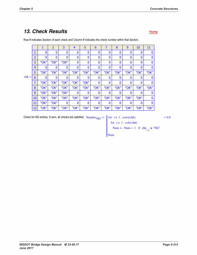
Chapter 5 Concrete Structures
WSDOT Bridge Design Manual M 23-50.17 Page 5-313 June 2017
13. Check Results
chk
=
NumberNG
Num Num 1+← chki j,
"NG"=if
j 1 cols chk( )..∈for
i 1 rows chk( )..∈for
Num
0.0=:=
FSfS
r θ'maxS α−( )⋅
z'oS θ'maxS⋅ ei.ship+ y θ'maxS⋅+
1.616=:=
chk12 11,
if FSfS 1.5≥ "OK", "NG", ( ) "OK"=:=
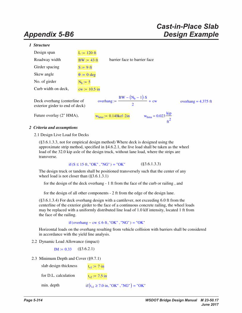
Page 5-314 WSDOT Bridge Design Manual M 23-50.17 June 2017
Cast-in-Place Slab Appendix 5-B6 Design Example
Design Example - Cast-in-Place Slab Design
1 Structure
Design span L 120 ft⋅:=
Roadway width BW 43 ft⋅:= barrier face to barrier face
Girder spacing S 9 ft⋅:=
Skew angle θ 0 deg⋅:=
No. of girder Nb 5:=
Curb width on deck, cw 10.5 in⋅:=
Deck overhang (centerline of
exterior girder to end of deck)overhang
BW Nb 1−( ) S⋅−
2cw+:= overhang 4.375 ft=
Future overlay (2" HMA), whma 0.140kcf 2⋅ in:= whma 0.023kip
ft2
=
2 Criteria and assumptions
2.1 Design Live Load for Decks
(§3.6.1.3.3, not for empirical design method) Where deck is designed using the
approximate strip method, specified in §4.6.2.1, the live load shall be taken as the wheel
load of the 32.0 kip axle of the design truck, without lane load, where the strips are
transverse.
if S 15 ft⋅≤ "OK", "NG",( ) "OK"= (§3.6.1.3.3)
The design truck or tandem shall be positioned transversely such that the center of any
wheel load is not closer than (§3.6.1.3.1)
for the design of the deck overhang - 1 ft from the face of the curb or railing , and
for the design of all other components - 2 ft from the edge of the design lane.
(§3.6.1.3.4) For deck overhang design with a cantilever, not exceeding 6.0 ft from the
centerline of the exterior girder to the face of a continuous concrete railing, the wheel loads
may be replaced with a uniformly distributed line load of 1.0 klf intensity, located 1 ft from
the face of the railing.
if overhang cw− 6 ft⋅≤ "OK", "NG",( ) "OK"=
Horizontal loads on the overhang resulting from vehicle collision with barriers shall be considered
in accordance with the yield line analysis.
2.2 Dynamic Load Allowance (impact)
IM 0.33:= (§3.6.2.1)
2.3 Minimum Depth and Cover (§9.7.1)
slab design thickness ts1 7 in⋅:=
for D.L. calculation ts2 7.5 in⋅:=
min. depth if ts1 7.0 in⋅≥ "OK", "NG",( ) "OK"=

Chapter 5 Concrete Structures
WSDOT Bridge Design Manual M 23-50.17 Page 5-315 June 2017
top concrete cover = 1.5 in. (up to #11 bar) (§5.12.4 & Table 5.12.3-1)
use 2.5 in. (Office Practice)
bottom concrete cover = 1 in. (up to #11 bar)
sacrificial thickness = 0.5 in. (§2.5.2.4)
2.4 Skew Deck (§9.7.1.3 and BDM §5.7.2 )
The primary reinforcement shall be placed perpendicular to the main supporting components.
3 Material Properties
3.1 Concrete
f'c 4 ksi⋅:= Use CLASS 4000D for bridge concrete deck (BDM 5.1.1)
fr2 0.37f'c
ksi⋅ ksi⋅:= fr2 0.74 ksi= (§5.4.2.6) for use in §5.7.3.3.2
wc 0.160 kcf⋅:=
Ec 33000wc
kcf
1.5
⋅
f'c
ksi⋅ ksi⋅:= Ec 4224.0 ksi= (§5.4.2.4)
3.2 Reinforcing Steel (§5.4.3)
fy 60 ksi⋅:= Es 29000 ksi⋅:=
4 Methods of Analysis
Concrete deck slabs may be analyzed by using
Approximate elastic methods of analysis, or
Refined methods of analysis, or
Empirical design.
Per office practice, concrete deck slab shall be designed and detailed for both empirical and
traditional design methods.
5 Empirical Design (§9.7.2)
5.1 Limit States (§9.5.1)
For other than the deck overhang, where empirical design is used, a concrete deck maybe
assumed to satisfy service, fatigue and fracture and strength limit states requirements.
Empirical design shall not be applied to overhangs (§9.7.2.2).
5.2 Design Conditions (§9.7.2.4)
For the purpose of empirical design method, the effective length S eff shall be taken as (§9.7.2.3),
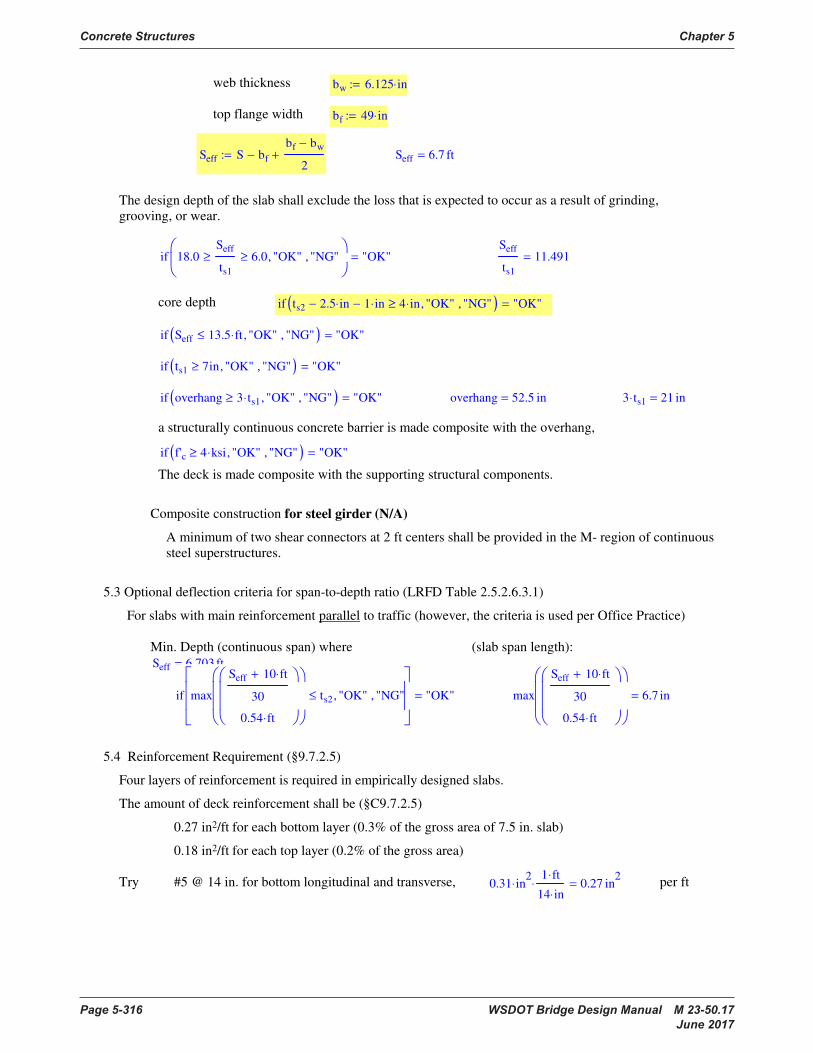
Concrete Structures Chapter 5
Page 5-316 WSDOT Bridge Design Manual M 23-50.17 June 2017
web thickness bw 6.125 in⋅:=
top flange width bf 49 in⋅:=
Seff S bf−
bf bw−
2+:= Seff 6.7 ft=
The design depth of the slab shall exclude the loss that is expected to occur as a result of grinding,
grooving, or wear.
if 18.0Seff
ts1
≥ 6.0≥ "OK", "NG",
"OK"=
Seff
ts1
11.491=
core depth if ts2 2.5 in⋅− 1 in⋅− 4 in⋅≥ "OK", "NG",( ) "OK"=
if Seff 13.5 ft⋅≤ "OK", "NG",( ) "OK"=
if ts1 7in≥ "OK", "NG",( ) "OK"=
if overhang 3 ts1⋅≥ "OK", "NG",( ) "OK"= overhang 52.5 in= 3 ts1⋅ 21 in=
a structurally continuous concrete barrier is made composite with the overhang,
if f'c 4 ksi⋅≥ "OK", "NG",( ) "OK"=
The deck is made composite with the supporting structural components.
Composite construction for steel girder (N/A)
A minimum of two shear connectors at 2 ft centers shall be provided in the M- region of continuous
steel superstructures.
5.3 Optional deflection criteria for span-to-depth ratio (LRFD Table 2.5.2.6.3.1)
For slabs with main reinforcement parallel to traffic (however, the criteria is used per Office Practice)
Min. Depth (continuous span) where
Seff 6.703 ft=
(slab span length):
if max
Seff 10 ft⋅+
30
0.54 ft⋅
ts2≤ "OK", "NG",
"OK"= max
Seff 10 ft⋅+
30
0.54 ft⋅
6.7 in=
5.4 Reinforcement Requirement (§9.7.2.5)
Four layers of reinforcement is required in empirically designed slabs.
The amount of deck reinforcement shall be (§C9.7.2.5)
0.27 in2/ft for each bottom layer (0.3% of the gross area of 7.5 in. slab)
0.18 in2/ft for each top layer (0.2% of the gross area)
Try #5 @ 14 in. for bottom longitudinal and transverse, 0.31 in2
⋅1 ft⋅
14 in⋅
⋅ 0.27 in2
= per ft
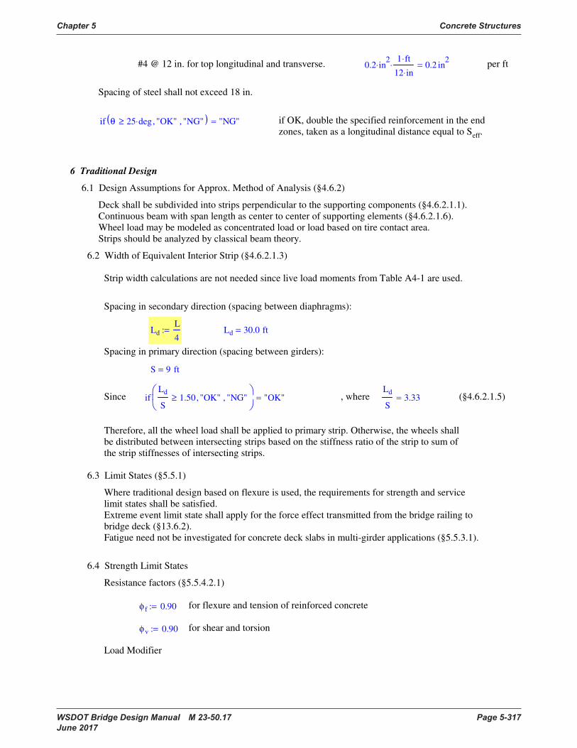
Chapter 5 Concrete Structures
WSDOT Bridge Design Manual M 23-50.17 Page 5-317 June 2017
#4 @ 12 in. for top longitudinal and transverse. 0.2 in2
⋅1 ft⋅
12 in⋅
⋅ 0.2 in2
= per ft
Spacing of steel shall not exceed 18 in.
if θ 25 deg⋅≥ "OK", "NG",( ) "NG"= if OK, double the specified reinforcement in the end
zones, taken as a longitudinal distance equal to Seff.
6 Traditional Design
6.1 Design Assumptions for Approx. Method of Analysis (§4.6.2)
Deck shall be subdivided into strips perpendicular to the supporting components (§4.6.2.1.1).
Continuous beam with span length as center to center of supporting elements (§4.6.2.1.6).
Wheel load may be modeled as concentrated load or load based on tire contact area.
Strips should be analyzed by classical beam theory.
6.2 Width of Equivalent Interior Strip (§4.6.2.1.3)
Strip width calculations are not needed since live load moments from Table A4-1 are used.
Spacing in secondary direction (spacing between diaphragms):
Ld
L
4:= Ld 30.0 ft=
Spacing in primary direction (spacing between girders):
S 9 ft=
Since ifLd
S1.50≥ "OK", "NG",
"OK"= , whereLd
S3.33= (§4.6.2.1.5)
Therefore, all the wheel load shall be applied to primary strip. Otherwise, the wheels shall
be distributed between intersecting strips based on the stiffness ratio of the strip to sum of
the strip stiffnesses of intersecting strips.
6.3 Limit States (§5.5.1)
Where traditional design based on flexure is used, the requirements for strength and service
limit states shall be satisfied.
Extreme event limit state shall apply for the force effect transmitted from the bridge railing to
bridge deck (§13.6.2).
Fatigue need not be investigated for concrete deck slabs in multi-girder applications (§5.5.3.1).
6.4 Strength Limit States
Resistance factors (§5.5.4.2.1)
φ f 0.90:= for flexure and tension of reinforced concrete
φv 0.90:= for shear and torsion
Load Modifier
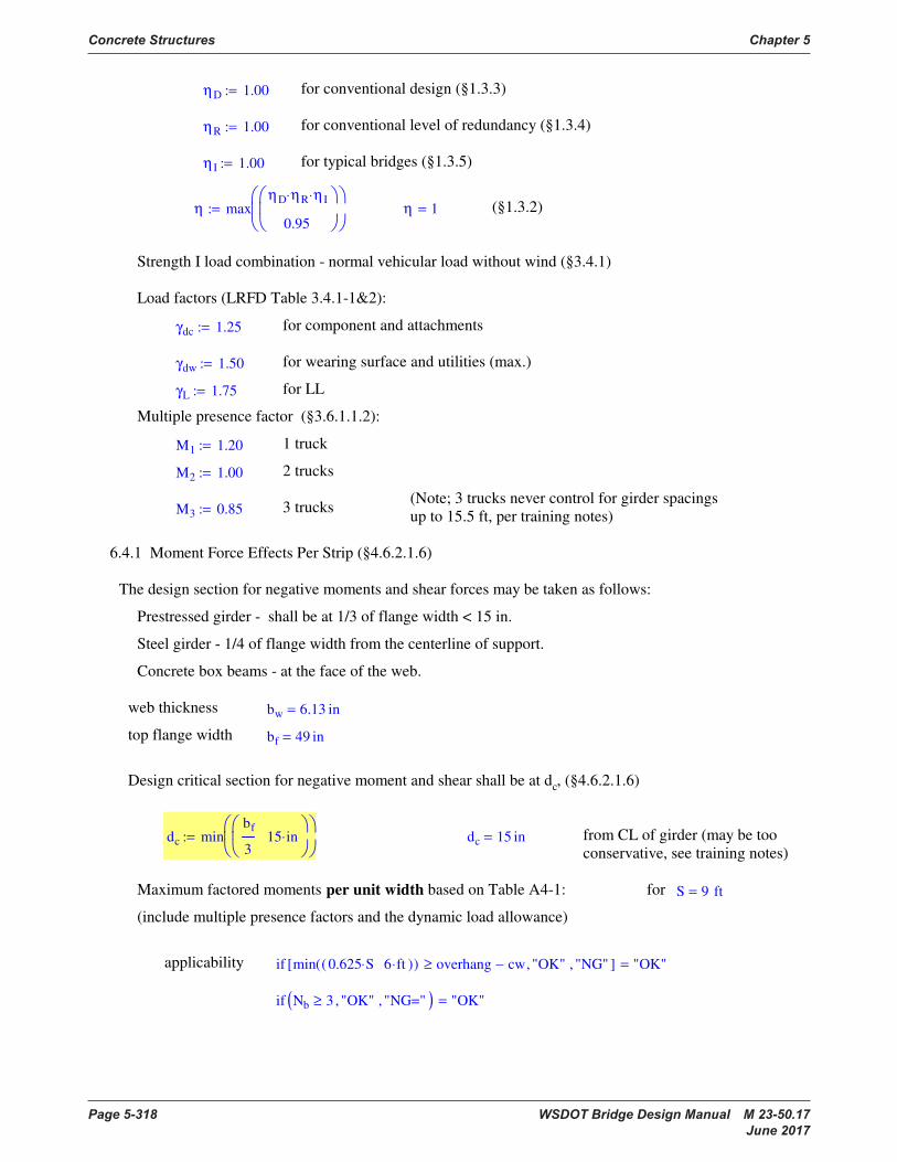
Concrete Structures Chapter 5
Page 5-318 WSDOT Bridge Design Manual M 23-50.17 June 2017
ηD 1.00:= for conventional design (§1.3.3)
ηR 1.00:= for conventional level of redundancy (§1.3.4)
η I 1.00:= for typical bridges (§1.3.5)
η maxηD ηR⋅ η I⋅
0.95
:= η 1= (§1.3.2)
Strength I load combination - normal vehicular load without wind (§3.4.1)
Load factors (LRFD Table 3.4.1-1&2):
γdc 1.25:= for component and attachments
γdw 1.50:= for wearing surface and utilities (max.)
γL 1.75:= for LL
Multiple presence factor (§3.6.1.1.2):
M1 1.20:= 1 truck
M2 1.00:= 2 trucks
(Note; 3 trucks never control for girder spacings
up to 15.5 ft, per training notes)M3 0.85:= 3 trucks
6.4.1 Moment Force Effects Per Strip (§4.6.2.1.6)
The design section for negative moments and shear forces may be taken as follows:
Prestressed girder - shall be at 1/3 of flange width < 15 in.
Steel girder - 1/4 of flange width from the centerline of support.
Concrete box beams - at the face of the web.
web thickness bw 6.13 in=
top flange width bf 49 in=
Design critical section for negative moment and shear shall be at dc, (§4.6.2.1.6)
dc minbf
315 in⋅
:= dc 15 in= from CL of girder (may be too
conservative, see training notes)
Maximum factored moments per unit width based on Table A4-1: for S 9 ft=
(include multiple presence factors and the dynamic load allowance)
applicability if min 0.625 S⋅ 6 ft⋅( )( ) overhang cw−≥ "OK", "NG",[ ] "OK"=
if Nb 3≥ "OK", "NG=",( ) "OK"=

Chapter 5 Concrete Structures
WSDOT Bridge Design Manual M 23-50.17 Page 5-319 June 2017
MLLp 6.29kip ft⋅
ft⋅:=
MLLn 3.51kip ft⋅
ft⋅:= (max. -M at dc from CL of girder)
Dead load moments
MDCp
ts2 wc⋅ S2
⋅
10:= MDCp 0.81
kip ft⋅
ft= (max. +M DC)
MDWp
whma S2
⋅
10:= MDWp 0.189
kip ft⋅
ft= (max. +M Dw)
MDCn MDCp:= MDCn 0.81kip ft⋅
ft= (max. -M DC at dc at interior girder)
MDWn MDWp:= (max. -M Dw at dc at interior girder)MDWn 0.189
kip ft⋅
ft=
Factored positive moment per ft
Mup η γdc MDCp⋅ γdw MDWp⋅+ γL MLLp⋅+( )⋅:= Mup 12.3kip ft⋅
ft=
Factored negative moment
Mun η γdc MDCn⋅ γdw MDWn⋅+ γL MLLn⋅+( )⋅:= Mun 7.44kip ft⋅
ft=
6.4.2 Flexural Resistance
Normal flexural resistance of a rectangular section may be determined by using equations for
a flanged section in which case bw shall be taken as b (§5.7.3.2.3).
β1 if f'c 4 ksi⋅≤ 0.85, 0.85 0.05f'c 4.0 ksi⋅−
1.0 ksi⋅
⋅−,
:= β1 β1 β1 0.65≥if
0.65 otherwise
:=
β1 0.85= (§5.7.2.2)
6.4.3 Design for Positive Moment Region
assume bar # barp 5:=
dia bar( ) 0.5 in⋅ bar 4=if
0.625 in⋅ bar 5=if
0.75 in⋅ bar 6=if
:=
dp ts1 1 in⋅−
dia barp( )
2−:= dp 5.7 in=
As
0.85 f'c⋅ ft⋅
fy
dp dp2 2 Mup⋅ ft⋅
0.85 φ f⋅ f'c⋅ ft⋅
−−
⋅:= As 0.52 in2
= per ft
use (bottom-transverse) # barp 5= sp 7.5 in⋅:= (max. spa. 12 in. per BDM
memo)

Concrete Structures Chapter 5
Page 5-320 WSDOT Bridge Design Manual M 23-50.17 June 2017
Ab bar( ) 0.20 in2
⋅ bar 4=if
0.31 in2
⋅ bar 5=if
0.44 in2
⋅ bar 6=if
:=
Asp Ab barp( )1 ft⋅
sp
⋅:= Asp 0.5 in2
= per ft
Check min. reinforcement (§5.7.3.3.2),
Mcr fr2
1
6⋅ 12⋅ in⋅ ts2
2⋅:= 1.2 Mcr⋅ 8.325 kip ft⋅= Mup ft⋅ 12.30 kip ft⋅=
if Mup ft⋅ 1.2 Mcr⋅≥ "OK", "NG",( ) "OK"=
6.4.4 Design for Negative Moment Region
assume bar # barn 5:=
dn ts1 2.0 in⋅−
dia barn( )
2−:= dn 4.69 in=
As
0.85 f'c⋅ ft⋅
fy
dn dn2 2 Mun⋅ ft⋅
0.85 φ f⋅ f'c⋅ ft⋅
−−
⋅:= As 0.37 in2
= per ft
use (top-transverse) bar # barn 5= sn 7.5 in⋅:= (max. spa. 12 in. per BDM
memo)
Asn Ab barn( )1 ft⋅
sn
⋅:= Asn 0.5 in2
= per ft
Check min. reinforcement (§5.7.3.3.2),
Mcr fr2
1
6⋅ 12⋅ in⋅ ts2
2⋅:= 1.2 Mcr⋅ 8.325 kip ft⋅= Mun ft⋅ 7.438 kip ft⋅=
if Mun ft⋅ 1.2 Mcr⋅≥ "OK", "NG",( ) "NG"=
Design for 1.2 Mcr,
0.85 f'c⋅ ft⋅
fy
dn dn2 2 1.2 Mcr⋅⋅
0.85 φ f⋅ f'c⋅ ft⋅
−−
⋅ 0.42 in2
= Say OK
6.5 Control of Cracking by Distribution of Reinforcement (§5.7.3.4)
Service I load combination is to be considered for crack width control (§3.4.1).

Chapter 5 Concrete Structures
WSDOT Bridge Design Manual M 23-50.17 Page 5-321 June 2017
Combined limit state load modifier (§1.3.2)
ηs 1:=
Load factors (LRFD Table 3.4.1-1):
γdc 1.00:= for component and attachments
γdw 1.00:= for wearing surface and utilities (max.)
γL 1.00:= for LL
Msp ηs γdc MDCp⋅ γdw MDWp⋅+ γL MLLp⋅+( )⋅:= Msp 7.29kip ft⋅
ft=
Msn ηs γdc MDCn⋅ γdw MDWn⋅+ γL MLLn⋅+( )⋅:= Msn 4.51kip ft⋅
ft=
γep 0.75:= for Class 2 exposure condition for deck (assumed)
γen 0.75:= for Class 2 exposure condition for deck (assumed)
h ts1:= h 7 in=
ρp
Asp
dp 12⋅ in⋅
:= ρn
Asn
dn 12⋅ in⋅
:=
nEs
Ec
:= n 6.866= n max ceil n 0.495−( )( ) 6[ ][ ]:=
set n 7= (round to nearest integer, §5.7.1, not less than 6)
k ρ( ) ρ n⋅( )2
2 ρ⋅ n⋅+ ρ n⋅−:= k ρp( ) 0.272=
j ρ( ) 1k ρ( )
3−:= j ρp( ) 0.909=
fsa
Msp ft⋅
Asp j ρp( )⋅ dp⋅
:= fsa 34.1 ksi=
for barp 5= sp 7.5 in=
dc 1 in⋅( )dia barp( )
2+:= dc 1.3 in= (the actual concrete cover is to be used
to compute dc)
βs 1dc
0.7 h dc−( )+:= βs 1.33=
if sp
700 γep⋅ in⋅
βs
fsa
ksi⋅
2 dc⋅−≤ "OK", "NG",
"OK"= where sp 7.5 in=
700 γep⋅ in⋅
βs
fsa
ksi⋅
2 dc⋅− 9.0 in=
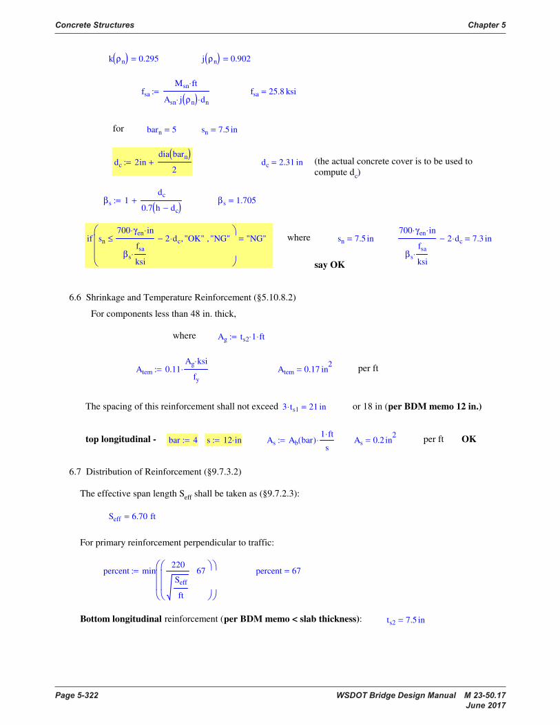
Concrete Structures Chapter 5
Page 5-322 WSDOT Bridge Design Manual M 23-50.17 June 2017
k ρn( ) 0.295= j ρn( ) 0.902=
fsa
Msn ft⋅
Asn j ρn( )⋅ dn⋅
:= fsa 25.8 ksi=
for barn 5= sn 7.5 in=
dc 2india barn( )
2+:= dc 2.31 in= (the actual concrete cover is to be used to
compute dc)
βs 1dc
0.7 h dc−( )+:= βs 1.705=
if sn
700 γen⋅ in⋅
βs
fsa
ksi⋅
2 dc⋅−≤ "OK", "NG",
"NG"= where sn 7.5 in=
700 γen⋅ in⋅
βs
fsa
ksi⋅
2 dc⋅− 7.3 in=
say OK
6.6 Shrinkage and Temperature Reinforcement (§5.10.8.2)
For components less than 48 in. thick,
where Ag ts2 1⋅ ft⋅:=
Atem 0.11Ag ksi⋅
fy
⋅:= Atem 0.17 in2
= per ft
The spacing of this reinforcement shall not exceed 3 ts1⋅ 21 in= or 18 in (per BDM memo 12 in.)
top longitudinal - bar 4:= s 12 in⋅:= As Ab bar( )1 ft⋅
s⋅:= As 0.2 in
2= per ft OK
6.7 Distribution of Reinforcement (§9.7.3.2)
The effective span length Seff shall be taken as (§9.7.2.3):
Seff 6.70 ft=
For primary reinforcement perpendicular to traffic:
percent min220
Seff
ft
67
:= percent 67=
Bottom longitudinal reinforcement (per BDM memo < slab thickness): ts2 7.5 in=
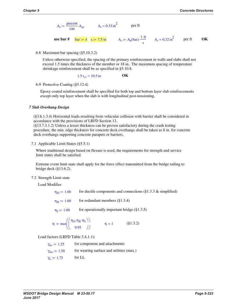
Chapter 5 Concrete Structures
WSDOT Bridge Design Manual M 23-50.17 Page 5-323 June 2017
As
percent
100Asp⋅:= As 0.33 in
2= per ft
use bar # bar 4:= s 7.5 in⋅:= As Ab bar( )1 ft⋅
s⋅:= As 0.32 in
2= per ft OK
6.8 Maximum bar spacing (§5.10.3.2)
Unless otherwise specified, the spacing of the primary reinforcement in walls and slabs shall not
exceed 1.5 times the thickness of the member or 18 in.. The maximum spacing of temperature
shrinkage reinforcement shall be as specified in §5.10.8.
1.5 ts1⋅ 10.5 in= OK
6.9 Protective Coating (§5.12.4)
Epoxy coated reinforcement shall be specified for both top and bottom layer slab reinforcements
except only top layer when the slab is with longitudinal post-tensioning.
7 Slab Overhang Design
(§3.6.1.3.4) Horizontal loads resulting from vehicular collision with barrier shall be considered in
accordance with the provisions of LRFD Section 13.
(§13.7.3.1.2) Unless a lesser thickness can be proven satisfactory during the crash testing
procedure, the min. edge thickness for concrete deck overhangs shall be taken as 8 in. for concrete
deck overhangs supporting concrete parapets or barriers.
7.1 Applicable Limit States (§5.5.1)
Where traditional design based on flexure is used, the requirements for strength and service
limit states shall be satisfied.
Extreme event limit state shall apply for the force effect transmitted from the bridge railing to
bridge deck (§13.6.2).
7.2 Strength Limit state
Load Modifier
ηD 1.00:= for ductile components and connections (§1.3.3 & simplified)
ηR 1.00:= for redundant members (§1.3.4)
η I 1.00:= for operationally important bridge (§1.3.5)
η maxηD ηR⋅ η I⋅
0.95
:= η 1= (§1.3.2)
Load factors (LRFD Table 3.4.1-1):
γdc 1.25:= for component and attachments
γdw 1.50:= for wearing surface and utilities (max.)
γL 1.75:= for LL
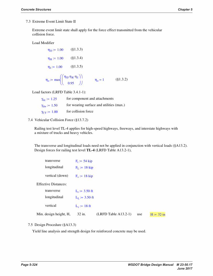
Concrete Structures Chapter 5
Page 5-324 WSDOT Bridge Design Manual M 23-50.17 June 2017
7.3 Extreme Event Limit State II
Extreme event limit state shall apply for the force effect transmitted from the vehicular
collision force.
Load Modifier
ηD 1.00:= (§1.3.3)
ηR 1.00:= (§1.3.4)
η I 1.00:= (§1.3.5)
ηe maxηD ηR⋅ η I⋅
0.95
:= ηe 1= (§1.3.2)
Load factors (LRFD Table 3.4.1-1):
γdc 1.25:= for component and attachments
γdw 1.50:= for wearing surface and utilities (max.)
γCT 1.00:= for collision force
7.4 Vehicular Collision Force (§13.7.2)
Railing test level TL-4 applies for high-speed highways, freeways, and interstate highways with
a mixture of trucks and heavy vehicles.
The transverse and longitudinal loads need not be applied in conjunction with vertical loads (§A13.2).
Design forces for railing test level TL-4 (LRFD Table A13.2-1),
transverse Ft 54 kip⋅:=
longitudinal FL 18 kip⋅:=
vertical (down) Fv 18 kip⋅:=
Effective Distances:
transverse Lt 3.50 ft⋅:=
longitudinal LL 3.50 ft⋅:=
vertical Lv 18 ft⋅:=
Min. design height, H, 32 in. (LRFD Table A13.2-1) use H 32 in⋅:=
7.5 Design Procedure (§A13.3)
Yield line analysis and strength design for reinforced concrete may be used.

Chapter 5 Concrete Structures
WSDOT Bridge Design Manual M 23-50.17 Page 5-325 June 2017
7.6 Nominal Railing Resistance (§A13.3)
For F-shape barriers, the approximate flexural resistance may be taken as:
Flexural capacity about vertical axis,
Mw 35.62 kip⋅ ft⋅:=
Additional flexural resistance of beam in addition to Mw , if any, at top of wall,
Mb 10.27 kip⋅ ft⋅:=
Flexural capacity about horizontal axis,
Mc 19.21kip ft⋅
ft⋅:=
Critical wall length, over which the yield mechanism occurs, Lc , shall be taken as:
Lc
Lt
2
Lt
2
28 H⋅ Mb Mw+( )⋅
Mc
++:= Lc 9.1 ft=
For impact within a barrier segment, the total transverse resistance of the railing may be taken as:
Rw
2
2 Lc⋅ Lt−
8 Mb⋅ 8 Mw⋅+
Mc Lc2
⋅
H+
⋅:= Rw 131.11 kip=
7.7 Design Load Cases (§A13.4.1)
Case 1
Transverse and longitudinal forces at extreme event limit state.
Resistance factor (§A13.4.3.2) φ 1.0:=
(§C13.7.3.1.2) Presently, in adequately designed bridge deck overhangs, the major
crash-related damage occurs in short sections of slab areas where the barriers is hit.
a. at inside face of parapet
Ms
min Rw 1.2 Ft⋅( )( ) H⋅
Lc 2 H⋅+
:= moment capacity of the base of the parapet (see memo),
Ms 11.97kip ft⋅
ft=
MDCa 0.45kip ft⋅
ft⋅:= DL M- at edge of curb (see
deck.gts STRUDL output),cw 0.875 ft=
design moment
Mu ηe γdc MDCa⋅ γCT Ms⋅+( )⋅:= Mu 12.5kip ft⋅
ft=
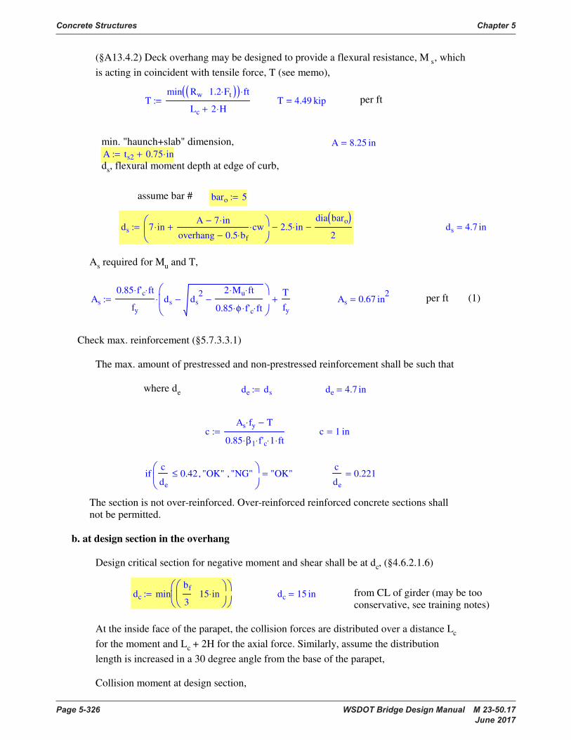
Concrete Structures Chapter 5
Page 5-326 WSDOT Bridge Design Manual M 23-50.17 June 2017
(§A13.4.2) Deck overhang may be designed to provide a flexural resistance, M s, which
is acting in coincident with tensile force, T (see memo),
Tmin Rw 1.2 Ft⋅( )( ) ft⋅
Lc 2 H⋅+
:= T 4.49 kip= per ft
min. "haunch+slab" dimension,
A ts2 0.75 in⋅+:=
A 8.25 in=
ds, flexural moment depth at edge of curb,
assume bar # baro 5:=
ds 7 in⋅A 7 in⋅−
overhang 0.5 bf⋅−
cw⋅+
2.5 in⋅−
dia baro( )
2−:= ds 4.7 in=
As required for Mu and T,
As
0.85 f'c⋅ ft⋅
fy
ds ds2 2 Mu⋅ ft⋅
0.85 φ⋅ f'c⋅ ft⋅
−−
⋅T
fy
+:= As 0.67 in2
= per ft (1)
Check max. reinforcement (§5.7.3.3.1)
The max. amount of prestressed and non-prestressed reinforcement shall be such that
where de de ds:= de 4.7 in=
cAs fy⋅ T−
0.85 β1⋅ f'c⋅ 1⋅ ft⋅
:= c 1 in=
ifc
de
0.42≤ "OK", "NG",
"OK"=c
de
0.221=
The section is not over-reinforced. Over-reinforced reinforced concrete sections shall
not be permitted.
b. at design section in the overhang
Design critical section for negative moment and shear shall be at dc, (§4.6.2.1.6)
dc minbf
315 in⋅
:= dc 15 in= from CL of girder (may be too
conservative, see training notes)
At the inside face of the parapet, the collision forces are distributed over a distance Lc
for the moment and Lc + 2H for the axial force. Similarly, assume the distribution
length is increased in a 30 degree angle from the base of the parapet,
Collision moment at design section,
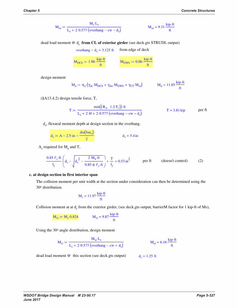
Chapter 5 Concrete Structures
WSDOT Bridge Design Manual M 23-50.17 Page 5-327 June 2017
Mse
Ms Lc⋅
Lc 2 0.577⋅ overhang cw− dc−( )⋅+
:= Mse 9.31kip ft⋅
ft=
dead load moment @ dc from CL of exterior girder (see deck.gts STRUDL output)
overhang dc− 3.125 ft= from edge of deck
MDCb 1.96kip ft⋅
ft⋅:= MDWb 0.06
kip ft⋅
ft⋅:=
design moment
Mu ηe γdc MDCb⋅ γdw MDWb⋅+ γCT Mse⋅+( )⋅:= Mu 11.85kip ft⋅
ft=
(§A13.4.2) design tensile force, T,
Tmin Rw 1.2 Ft⋅( )( ) ft⋅
Lc 2 H⋅+ 2 0.577⋅ overhang cw− dc−( )⋅+
:= T 3.81 kip= per ft
ds, flexural moment depth at design section in the overhang.
ds A 2.5 in⋅−
dia baro( )
2−:= ds 5.4 in=
As required for Mu and T,
0.85 f'c⋅ ft⋅
fy
ds ds2 2 Mu⋅ ft⋅
0.85 φ⋅ f'c⋅ ft⋅
−−
⋅T
fy
+ 0.53 in2
= per ft (doesn't control) (2)
c. at design section in first interior span
The collision moment per unit width at the section under consideration can then be determined using the
30o distribution.
Ms 11.97kip ft⋅
ft=
Collision moment at at dc from the exterior girder, (see deck.gts output, barrierM factor for 1 kip-ft of Ms),
Msi Ms 0.824⋅:= Msi 9.87kip ft⋅
ft=
Using the 30o angle distribution, design moment
Msi
Msi Lc⋅
Lc 2 0.577⋅ overhang cw− dc+( )⋅+
:= Msi 6.16kip ft⋅
ft=
dead load moment @ this section (see deck.gts output) dc 1.25 ft=

Concrete Structures Chapter 5
Page 5-328 WSDOT Bridge Design Manual M 23-50.17 June 2017
MDCi 2.11kip ft⋅
ft⋅:= MDWi 0.03
kip ft⋅
ft⋅:=
design moment
Mu ηe γdc MDCi⋅ γdw MDWi⋅+ γCT Msi⋅+( )⋅:= Mu 8.84kip ft⋅
ft=
ds, flexural moment depth at the design section,
ds ts1 2.0 in⋅−
dia baro( )
2−:= ds 4.69 in=
As required for Mu,
0.85 f'c⋅ ft⋅
fy
ds ds2 2 Mu⋅ ft⋅
0.85 φ⋅ f'c⋅ ft⋅
−−
⋅ 0.4 in2
= per ft (doesn't control) (3)
Case 2 Vertical collision force
For concrete parapets, the case of vertical collision never controls.
Case 3 Check DL + LL
Resistance factor (§1.3.2.1) φ f 0.9:=
For deck overhangs, where applicable, the §3.6.1.3.4 may be used in lieu of the equivalent strip
method (§4.6.2.1.3).
a. at design section in the overhang
moment arm for 1.0 kip/ft live load (§3.6.1.3.4)
x overhang cw− 1 ft⋅− dc−:= x 15 in=
live load moment without impact,
wL 1.0kip
ft⋅:=
MLL M1 wL⋅ x⋅:= MLL 1.5kip ft⋅
ft=
factored moment
Mu η γdc MDCb⋅ γdw MDWb⋅+ γL MLL⋅ 1.0 IM+( )⋅+ ⋅:= Mu 6.03kip ft⋅
ft=
ds, flexural moment depth at edge of curb,
ds A 2.5 in⋅−
dia baro( )
2−:= ds 5.44 in=
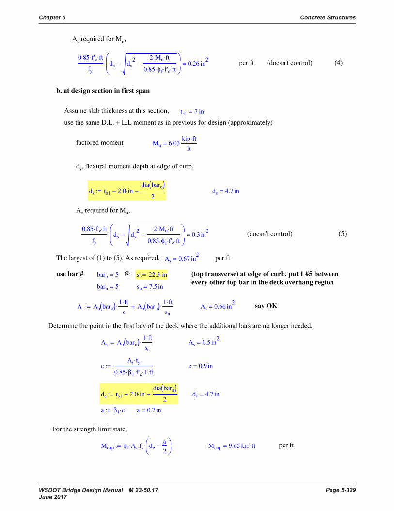
Chapter 5 Concrete Structures
WSDOT Bridge Design Manual M 23-50.17 Page 5-329 June 2017
As required for Mu,
0.85 f'c⋅ ft⋅
fy
ds ds2 2 Mu⋅ ft⋅
0.85 φ f⋅ f'c⋅ ft⋅
−−
⋅ 0.26 in2
= per ft (doesn't control) (4)
b. at design section in first span
Assume slab thickness at this section, ts1 7 in=
use the same D.L. + L.L moment as in previous for design (approximately)
factored moment Mu 6.03kip ft⋅
ft=
ds, flexural moment depth at edge of curb,
ds ts1 2.0 in⋅−
dia baro( )
2−:= ds 4.7 in=
As required for Mu,
0.85 f'c⋅ ft⋅
fy
ds ds2 2 Mu⋅ ft⋅
0.85 φ f⋅ f'c⋅ ft⋅
−−
⋅ 0.3 in2
= (doesn't control) (5)
The largest of (1) to (5), As required, As 0.67 in2
= per ft
use bar # baro 5= @ s 22.5 in⋅:= (top transverse) at edge of curb, put 1 #5 between
every other top bar in the deck overhang regionbarn 5= sn 7.5 in=
As Ab baro( )1 ft⋅
s⋅ Ab barn( )
1 ft⋅
sn
⋅+:= As 0.66 in2
= say OK
Determine the point in the first bay of the deck where the additional bars are no longer needed,
As Ab barn( )1 ft⋅
sn
⋅:= As 0.5 in2
=
cAs fy⋅
0.85 β1⋅ f'c⋅ 1⋅ ft⋅
:= c 0.9 in=
de ts1 2.0 in⋅−
dia barn( )
2−:= de 4.7 in=
a β1 c⋅:= a 0.7 in=
For the strength limit state,
Mcap φ f As⋅ fy⋅ de
a
2−
⋅:= Mcap 9.65 kip ft⋅= per ft

Concrete Structures Chapter 5
Page 5-330 WSDOT Bridge Design Manual M 23-50.17 June 2017
For the extreme event limit state,
Mcap φ As⋅ fy⋅ de
a
2−
⋅:= Mcap 10.72 kip ft⋅= per ft
By inspection of (1) to (5), no additional bar is required beyond design section of the first bay.
Cut off length requirement (§5.11.1.2)
15 dia baro( )⋅ 0.781 ft= (controls by inspection)
8 Reinforcing Details
8.1 Development of Reinforcement (§5.11.2.1.1)
basic development length for #11 bar and smaller,
Ldb db Ab,( ) max
1.0 ft⋅
1.25 Ab⋅ fy⋅ ksi⋅
in ksi⋅ f'c⋅
0.4 db⋅
fy
ksi⋅
:=
For #5 bars, Ldb 0.625 in⋅ 0.31 in2
⋅,( ) 15 in=
For #6 bars, Ldb 0.75 in⋅ 0.44 in2
⋅,( ) 18 in=
For epoxy coated bars (§5.11.2.1.2),
with cover less than 3db or with clear spacing less than 6db ..........times 1.5
not covered above ......times 1.2
For widely spaced bars..... times 0.8 (§5.11.2.1.3)
bars spaced laterally not less than 6 in. center-to-center, with not less than 3. in clear
cover measured in the direction of spacing.
For bundled bars..... times 1.2 for a three-bar bundle (§5.11.2.3)
Lap Splices in Tension (§5.11.5.3.1)
The length of lap for tension lap splices shall not be less than either 12 in. or the following for Class
A, B, or C splices:
Class A splice ........ times 1.0
Class B splice ........ times 1.3
Class C splice ........ times 1.7
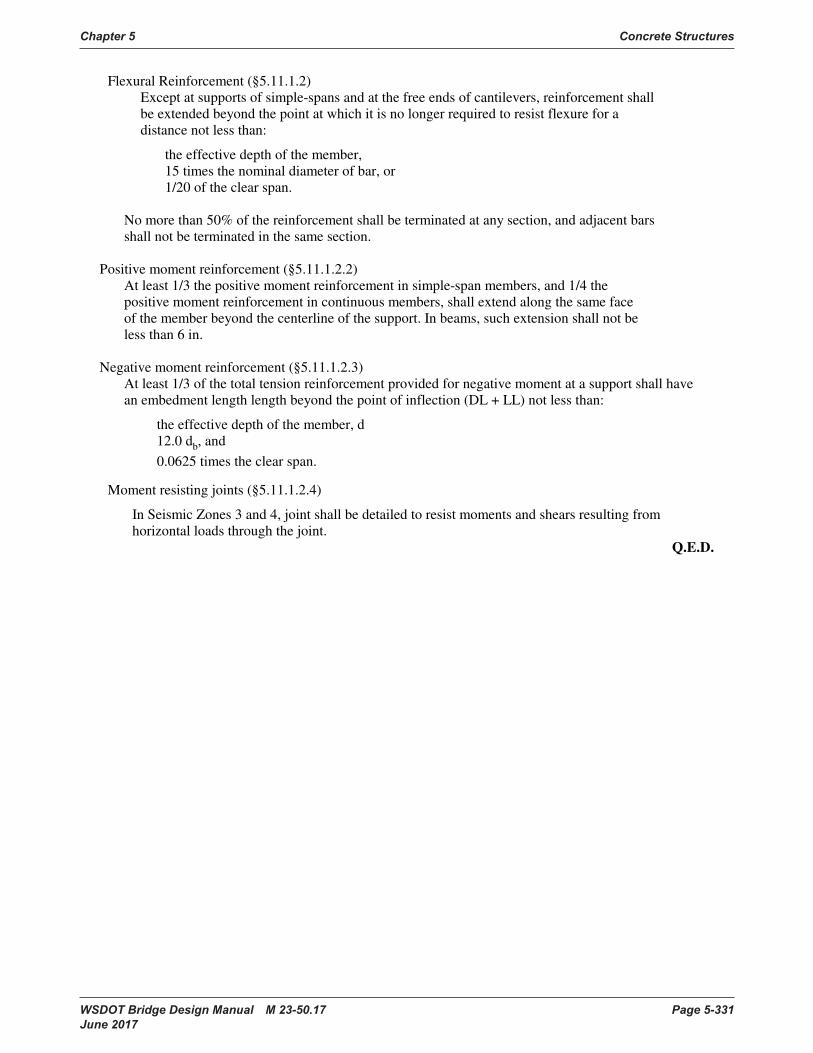
Chapter 5 Concrete Structures
WSDOT Bridge Design Manual M 23-50.17 Page 5-331 June 2017
Flexural Reinforcement (§5.11.1.2)
Except at supports of simple-spans and at the free ends of cantilevers, reinforcement shall
be extended beyond the point at which it is no longer required to resist flexure for a
distance not less than:
the effective depth of the member,
15 times the nominal diameter of bar, or
1/20 of the clear span.
No more than 50% of the reinforcement shall be terminated at any section, and adjacent bars
shall not be terminated in the same section.
Positive moment reinforcement (§5.11.1.2.2)
At least 1/3 the positive moment reinforcement in simple-span members, and 1/4 the
positive moment reinforcement in continuous members, shall extend along the same face
of the member beyond the centerline of the support. In beams, such extension shall not be
less than 6 in.
Negative moment reinforcement (§5.11.1.2.3)
At least 1/3 of the total tension reinforcement provided for negative moment at a support shall have
an embedment length length beyond the point of inflection (DL + LL) not less than:
the effective depth of the member, d
12.0 db, and
0.0625 times the clear span.
Moment resisting joints (§5.11.1.2.4)
In Seismic Zones 3 and 4, joint shall be detailed to resist moments and shears resulting from
horizontal loads through the joint.
Q.E.D.
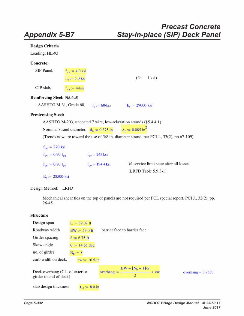
Page 5-332 WSDOT Bridge Design Manual M 23-50.17 June 2017
Precast Concrete Appendix 5-B7 Stay-in-place (SIP) Deck PanelPrecast Concrete Stay-In-Place (SIP) Deck Panel
Design Criteria
Loading: HL-93
Concrete:
SIP Panel, f'ci 4.0 ksi⋅:=
f'c 5.0 ksi⋅:= (f'ci + 1 ksi)
CIP slab, f'cs 4 ksi⋅:=
Reinforcing Steel: (§5.4.3)
AASHTO M-31, Grade 60, fy 60 ksi⋅:= Es 29000 ksi⋅:=
Prestressing Steel:
AASHTO M-203, uncoated 7 wire, low-relaxation strands (§5.4.4.1)
Nominal strand diameter, db 0.375 in⋅:= Ap 0.085 in2
⋅:=
(Trends now are toward the use of 3/8 in. diameter strand, per PCI J., 33(2), pp.67-109)
fpu 270 ksi⋅:=
fpy 0.90 fpu⋅:= fpy 243 ksi=
fpe 0.80 fpy⋅:= fpe 194.4 ksi= @ service limit state after all losses
(LRFD Table 5.9.3-1)
Ep 28500 ksi⋅:=
Design Method: LRFD
Mechanical shear ties on the top of panels are not required per PCI, special report, PCI J., 32(2), pp.
26-45.
Structure
Design span L 89.07 ft⋅:=
Roadway width BW 53.0 ft⋅:= barrier face to barrier face
Girder spacing S 6.75 ft⋅:=
Skew angle θ 14.65 deg⋅:=
no. of girder Nb 8:=
curb width on deck, cw 10.5 in⋅:=
Deck overhang (CL. of exterior
girder to end of deck)overhang
BW Nb 1−( ) S⋅−
2cw+:= overhang 3.75 ft=
slab design thickness ts1 8.0 in⋅:=
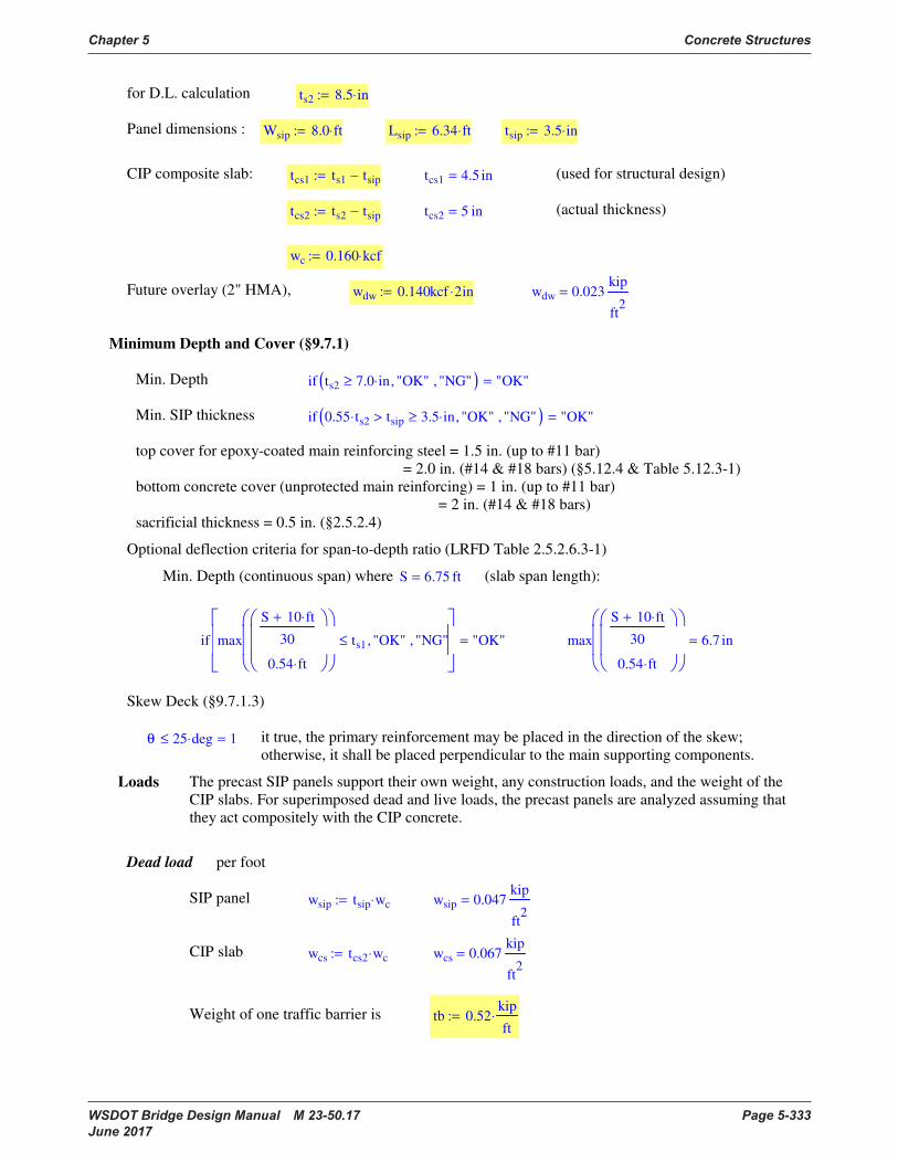
Chapter 5 Concrete Structures
WSDOT Bridge Design Manual M 23-50.17 Page 5-333 June 2017
for D.L. calculation ts2 8.5 in⋅:=
Panel dimensions : Wsip 8.0 ft⋅:= Lsip 6.34 ft⋅:= tsip 3.5 in⋅:=
CIP composite slab: tcs1 ts1 tsip−:= tcs1 4.5 in= (used for structural design)
tcs2 ts2 tsip−:= tcs2 5 in= (actual thickness)
wc 0.160 kcf⋅:=
Future overlay (2" HMA), wdw 0.140kcf 2⋅ in:= wdw 0.023kip
ft2
=
Minimum Depth and Cover (§9.7.1)
Min. Depth if ts2 7.0 in⋅≥ "OK", "NG",( ) "OK"=
Min. SIP thickness if 0.55 ts2⋅ tsip> 3.5 in⋅≥ "OK", "NG",( ) "OK"=
top cover for epoxy-coated main reinforcing steel = 1.5 in. (up to #11 bar)
= 2.0 in. (#14 & #18 bars) (§5.12.4 & Table 5.12.3-1)
bottom concrete cover (unprotected main reinforcing) = 1 in. (up to #11 bar)
= 2 in. (#14 & #18 bars)
sacrificial thickness = 0.5 in. (§2.5.2.4)
Optional deflection criteria for span-to-depth ratio (LRFD Table 2.5.2.6.3-1)
Min. Depth (continuous span) where S 6.75 ft= (slab span length):
if max
S 10 ft⋅+
30
0.54 ft⋅
ts1≤ "OK", "NG",
"OK"= max
S 10 ft⋅+
30
0.54 ft⋅
6.7 in=
Skew Deck (§9.7.1.3)
θ 25 deg⋅≤ 1= it true, the primary reinforcement may be placed in the direction of the skew;
otherwise, it shall be placed perpendicular to the main supporting components.
Loads The precast SIP panels support their own weight, any construction loads, and the weight of the
CIP slabs. For superimposed dead and live loads, the precast panels are analyzed assuming that
they act compositely with the CIP concrete.
Dead load per foot
SIP panel wsip tsip wc⋅:= wsip 0.047kip
ft2
=
CIP slab wcs tcs2 wc⋅:= wcs 0.067kip
ft2
=
Weight of one traffic barrier is tb 0.52kip
ft⋅:=

Concrete Structures Chapter 5
Page 5-334 WSDOT Bridge Design Manual M 23-50.17 June 2017
Weight of one sidewalk is tside 0.52kip
ft⋅:=
Wearing surface &
construction loads
future wearing surface wdw 0.023kip
ft2
=
construction load
(applied to deck panel only)wcon 0.050
kip
ft⋅:= (§9.7.4.1)
Note that load factor for construction load is 1.5 (§3.4.2).
Live loads
(§3.6.1.3.3, not for empirical design method) Where deck is designed using the approximate strip
method, specified in §4.6.2.1, the live load shall be taken as the wheel load of the 32.0 kip axle of the
design truck, without lane load, where the strips are transverse.
if S 15 ft⋅≤ "OK", "NG",( ) "OK"= (§3.6.1.3.3)
Multiple presence factor: M1 1.2:= M2 1.0:= (§3.6.1.1.1.2)
Dynamic Load Allowance (impact) IM 0.33:= (§3.6.2.1)
Maximum factored moments per unit width based on Table A4-1: for S 6.75 ft=
(include the effect of multiple presence factors and the dynamic load allowance)
applicability if min 0.625 S⋅ 6 ft⋅( )( ) overhang cw−≥ "OK", "NG",[ ] "OK"=
if Nb 3≥ "OK", "NG",( ) "OK"=
MLLp 5.10kip ft⋅
ft⋅:=
(§3.6.1.3.4) For deck overhang design with a cantilever, not exceeding 6.0 ft from the
centerline of the exterior girder to the face of a continuous concrete railing, the wheel loads
may be replaced with a uniformly distributed line load of 1.0 KLF intensity, located 1 ft from
the face of the railing.
if overhang cw− 6 ft⋅≤ "OK", "NG",( ) "OK"=
Load combination
Where traditional design based on flexure is used, the requirements for strength and service
limit states shall be satisfied.
Extreme event limit state shall apply for the force effect transmitted from the bridge railing to
bridge deck (§13.6.2).
Fatigue need not be investigated for concrete deck slabs in multi-girder applications (§5.5.3.1).
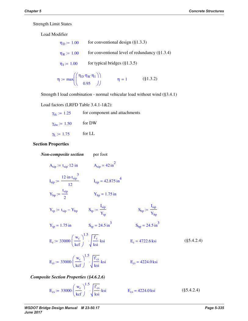
Chapter 5 Concrete Structures
WSDOT Bridge Design Manual M 23-50.17 Page 5-335 June 2017
Strength Limit States
Load Modifier
ηD 1.00:= for conventional design (§1.3.3)
ηR 1.00:= for conventional level of redundancy (§1.3.4)
η I 1.00:= for typical bridges (§1.3.5)
η maxηD ηR⋅ η I⋅
0.95
:= η 1= (§1.3.2)
Strength I load combination - normal vehicular load without wind (§3.4.1)
Load factors (LRFD Table 3.4.1-1&2):
γdc 1.25:= for component and attachments
γdw 1.50:= for DW
γL 1.75:= for LL
Section Properties
Non-composite section per foot
Asip tsip 12⋅ in⋅:= Asip 42 in2
=
Isip
12 in⋅ tsip3
⋅
12:= Isip 42.875 in
4=
Ybp
tsip
2:= Ybp 1.75 in=
Ytp tsip Ybp−:= Stp
Isip
Ytp
:= Sbp
Isip
Ybp
:=
Ytp 1.75 in= Stp 24.5 in3
= Sbp 24.5 in3
=
Ec 33000wc
kcf
1.5
⋅
f'c
ksi⋅ ksi⋅:= Ec 4722.6 ksi= (§5.4.2.4)
Eci 33000wc
kcf
1.5
⋅
f'ci
ksi⋅ ksi⋅:= Eci 4224.0 ksi=
Composite Section Properties (§4.6.2.6)
Ecs 33000wc
kcf
1.5
⋅
f'cs
ksi⋅ ksi⋅:= Ecs 4224.0 ksi= (§5.4.2.4)
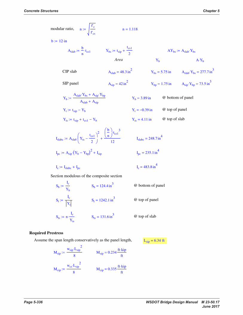
Concrete Structures Chapter 5
Page 5-336 WSDOT Bridge Design Manual M 23-50.17 June 2017
modular ratio, nf'c
f'cs
:= n 1.118=
b 12 in⋅:=
Aslab
b
ntcs1⋅:= Ybs tsip
tcs1
2+:= AYbs Aslab Ybs⋅:=
Area Yb A Yb⋅
CIP slab Aslab 48.3 in2
= Ybs 5.75 in= Aslab Ybs⋅ 277.7 in3
=
SIP panel Asip 42 in2
= Ybp 1.75 in= Asip Ybp⋅ 73.5 in3
=
Yb
Aslab Ybs⋅ Asip Ybp⋅+
Aslab Asip+
:= Yb 3.89 in= @ bottom of panel
Yt tsip Yb−:= Yt 0.39− in= @ top of panel
Yts tsip tcs1+ Yb−:= Yts 4.11 in= @ top of slab
Islabc Aslab Yts
tcs1
2−
2
⋅
b
n
tcs13
⋅
12+:= Islabc 248.7 in
4=
Ipc Asip Yb Ybp−( )2
⋅ Isip+:= Ipc 235.1 in4
=
Ic Islabc Ipc+:= Ic 483.8 in4
=
Section modulous of the composite section
Sb
Ic
Yb
:= Sb 124.4 in3
= @ bottom of panel
St
Ic
Yt
:= St 1242.1 in3
= @ top of panel
Sts nIc
Yts
⋅:= Sts 131.6 in3
= @ top of slab
Required Prestress
Assume the span length conservatively as the panel length, Lsip 6.34 ft=
Msip
wsip Lsip2
⋅
8:= Msip 0.234
ft kip⋅
ft=
Mcip
wcs Lsip2
⋅
8:= Mcip 0.335
ft kip⋅
ft=
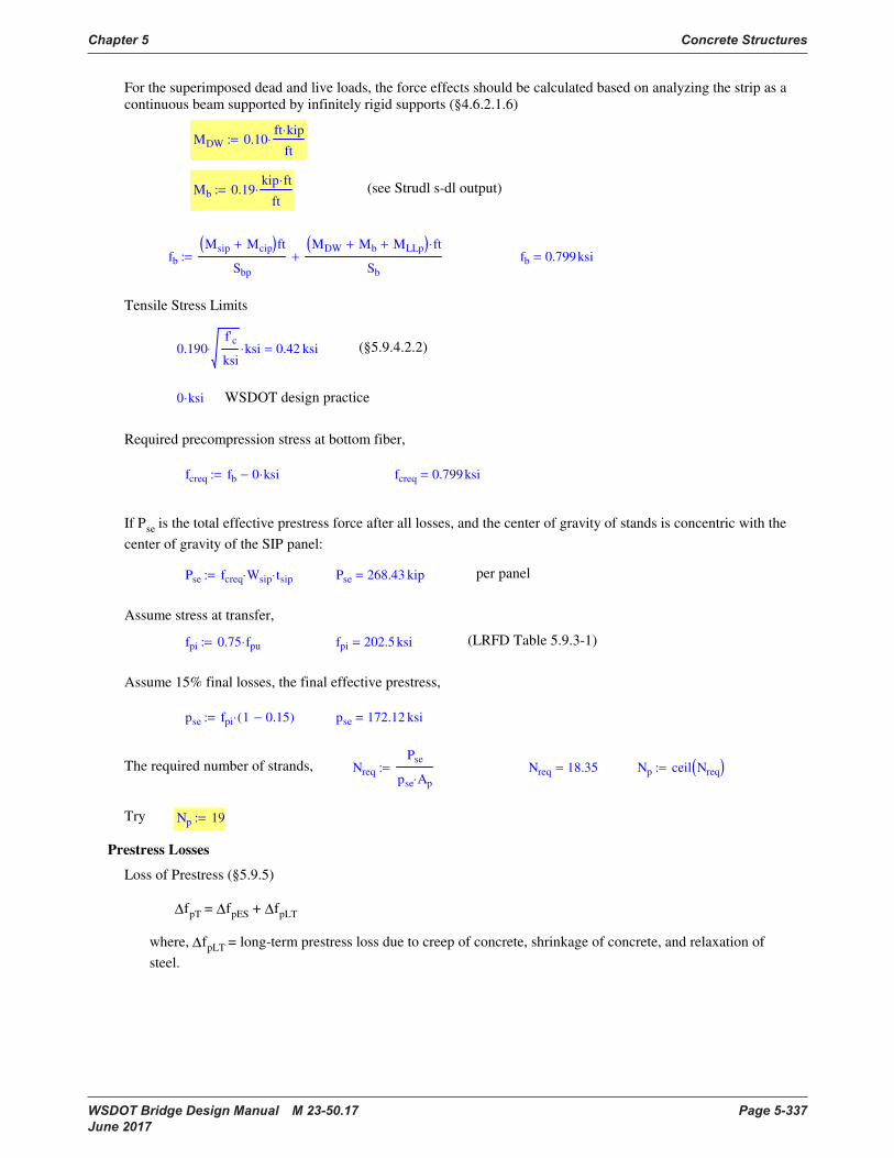
Chapter 5 Concrete Structures
WSDOT Bridge Design Manual M 23-50.17 Page 5-337 June 2017
For the superimposed dead and live loads, the force effects should be calculated based on analyzing the strip as a
continuous beam supported by infinitely rigid supports (§4.6.2.1.6)
MDW 0.10ft kip⋅
ft⋅:=
Mb 0.19kip ft⋅
ft⋅:= (see Strudl s-dl output)
fb
Msip Mcip+( )ft
Sbp
MDW Mb+ MLLp+( ) ft⋅
Sb
+:= fb 0.799ksi=
Tensile Stress Limits
0.190f'c
ksi⋅ ksi⋅ 0.42 ksi= (§5.9.4.2.2)
0 ksi⋅ WSDOT design practice
Required precompression stress at bottom fiber,
fcreq fb 0 ksi⋅−:= fcreq 0.799ksi=
If Pse is the total effective prestress force after all losses, and the center of gravity of stands is concentric with the
center of gravity of the SIP panel:
Pse fcreq Wsip⋅ tsip⋅:= Pse 268.43 kip= per panel
Assume stress at transfer,
fpi 0.75 fpu⋅:= fpi 202.5 ksi= (LRFD Table 5.9.3-1)
Assume 15% final losses, the final effective prestress,
pse fpi 1 0.15−( )⋅:= pse 172.12 ksi=
The required number of strands, Nreq
Pse
pse Ap⋅
:= Nreq 18.35= Np ceil Nreq( ):=
Try Np 19:=
Prestress Losses
Loss of Prestress (§5.9.5)
∆fpT = ∆fpES + ∆fpLT
where, ∆fpLT = long-term prestress loss due to creep of concrete, shrinkage of concrete, and relaxation of
steel.
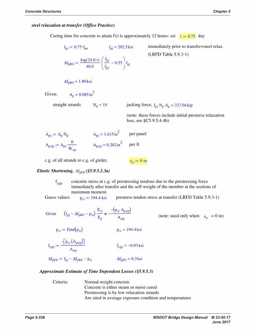
Concrete Structures Chapter 5
Page 5-338 WSDOT Bridge Design Manual M 23-50.17 June 2017
steel relaxation at transfer (Office Practice)
Curing time for concrete to attain f'ci is approximately 12 hours: set t 0.75:= day
fpj 0.75 fpu⋅:= fpj 202.5 ksi= immediately prior to transfer+steel relax.
(LRFD Table 5.9.3-1)
∆fpR0
log 24.0 t⋅( )
40.0
fpj
fpy
0.55−
⋅ fpj⋅:=
∆fpR0 1.80 ksi=
Given: Ap 0.085 in2
=
straight strands Np 19= jacking force, fpj Np⋅ Ap⋅ 327.04 kip=
(note: these forces include initial prestress relaxation
loss, see §C5.9.5.4.4b)
Aps Ap Np⋅:= Aps 1.615 in2
= per panel
Apsip Aps
ft
Wsip
⋅:= Apsip 0.202 in2
= per ft
c.g. of all strands to c.g. of girder, ep 0 in⋅:=
Elastic Shortening, ∆fpES (§5.9.5.2.3a)
fcgp: concrete stress at c.g. of prestressing tendons due to the prestressing force
immediately after transfer and the self-weight of the member at the sections of
maximum moment.
Guess values: psi 194.4 ksi⋅:= prestress tendon stress at transfer (LRFD Table 5.9.3-1)
Given fpj ∆fpR0− psi−( )Eci
Ep
⋅
psi Apsip⋅( )−
Asip
−=(note: used only when ep = 0 in)
psi Find psi( ):= psi 194.4 ksi=
fcgp
psi Apsip( )⋅ −
Asip
:= fcgp 0.93− ksi=
∆fpES fpj ∆fpR0− psi−:= ∆fpES 6.3 ksi=
Approximate Estimate of Time Dependent Losses (§5.9.5.3)
Criteria: Normal-weight concrete
Concrete is either steam or moist cured
Prestressing is by low relaxation strands
Are sited in average exposure condition and temperatures
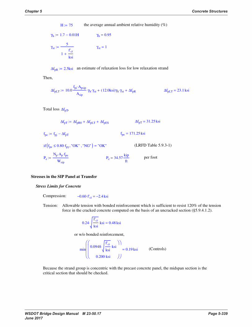
Chapter 5 Concrete Structures
WSDOT Bridge Design Manual M 23-50.17 Page 5-339 June 2017
H 75:= the average annual ambient relative humidity (%)
γh 1.7 0.01H−:= γh 0.95=
γst
5
1f'ci
ksi+
:= γst 1=
∆fpR 2.5ksi:= an estimate of relaxation loss for low relaxation strand
Then,
∆fpLT 10.0fpi Apsip⋅
Asip
γh⋅ γst⋅ 12.0ksi( )γh γst⋅+ ∆fpR+:= ∆fpLT 23.1 ksi=
Total loss ∆fpT,
∆fpT ∆fpR0 ∆fpLT+ ∆fpES+:= ∆fpT 31.25 ksi=
fpe fpj ∆fpT−:= fpe 171.25 ksi=
if fpe 0.80 fpy⋅≤ "OK", "NG",( ) "OK"= (LRFD Table 5.9.3-1)
Pe
Np Ap⋅ fpe⋅
Wsip
:= Pe 34.57kip
ft= per foot
Stresses in the SIP Panel at Transfer
Stress Limits for Concrete
Compression: 0.60− f'ci⋅ 2.4− ksi=
Tension: Allowable tension with bonded reinforcement which is sufficient to resist 120% of the tension
force in the cracked concrete computed on the basis of an uncracked section (§5.9.4.1.2).
0.24f'ci
ksi⋅ ksi⋅ 0.48 ksi=
or w/o bonded reinforcement,
min0.0948
f'ci
ksi⋅ ksi⋅
0.200 ksi⋅
0.19 ksi= (Controls)
Because the strand group is concentric with the precast concrete panel, the midspan section is the
critical section that should be checked.

Concrete Structures Chapter 5
Page 5-340 WSDOT Bridge Design Manual M 23-50.17 June 2017
Stress at Midspan
Effective stress after transfer,
Psi
Np Ap⋅ psi⋅
Wsip
:= Psi 39.244kip
ft=
Moment due to weight of the panel,
Msip 0.234kip ft⋅
ft=
At top of the SIP panel,
Msip ft⋅
Stp
−
Psi ft⋅
Asip
−
1.05− ksi= < allowable 0.60− f'ci⋅ 2.4− ksi= OK
At bottom of the SIP panel,
Msip ft⋅
Sbp
Psi ft⋅
Asip
−
0.82− ksi= < allowable 0.60− f'ci⋅ 2.4− ksi= OK
Stresses in SIP Panel at Time of Casting Topping Slab
The total prestress after all losses,
Pe 34.57kip
ft=
Stress Limits for Concrete
Flexural stresses due to unfactored construction loads shall not exceed 65% of the 28-day compressive
strength for concrete in compression or the modulus of rupture in tension for prestressed concrete form
panels (§9.7.4.1).
The construction load shall be taken to be less than the weight of the form and the concrete slab plus 0.050 KSF.
For load combination Service I:
Compression: 0.65− f'c⋅ 3.25− ksi=
Tension: Modulous of rupture,
fr 0.24f'c
ksi⋅ ksi⋅:= fr 0.54 ksi=
Stresses at Midspan after all Non-Composite Loads
Msip 0.23ft kip⋅
ft=

Chapter 5 Concrete Structures
WSDOT Bridge Design Manual M 23-50.17 Page 5-341 June 2017
Mcip 0.33ft kip⋅
ft=
Mconst 0.050kip
ft2
⋅
Lsip2
8:= Mconst 0.25
ft kip⋅
ft=
At top of the SIP panel,
Msip Mcip+ Mconst+( ) ft⋅
Stp
−
Pe ft⋅
Asip
−
1.23− ksi= < allowable 0.65− f'c⋅ 3.25− ksi= OK
At bottom of the SIP panel,
Msip Mcip+ Mconst+( ) ft⋅
Sbp
Pe ft⋅
Asip
−
0.42− ksi= < allowable 0.65− f'c⋅ 3.25− ksi= OK
Elastic Deformation (§9.7.4.1)
Deformation due to
∆5
48
Msip Mcip+( ) ft⋅ Lsip2
⋅
Ec Isip⋅
⋅:= ∆ 0.02 in=
if ∆ minLsip
1800.25 in⋅
Lsip 10 ft⋅≤if
minLsip
2400.75 in⋅
otherwise
≤ "OK", "NG",
"OK"=
Stresses in SIP Panel at Service Loads
Compression:
Stresses due to permanent loads•
0.45− f'c⋅ 2.25− ksi= for SIP panel
0.45− f'cs⋅ 1.8− ksi= for CIP panel
Stresses due to permanent and transient loads•
0.60− f'c⋅ 3− ksi= for SIP panel
0.60− f'cs⋅ 2.4− ksi= for CIP panel
Stresses due to live load + one-half of the permanent loads•
0.40− f'c⋅ 2− ksi= for SIP panel
0.40− f'cs⋅ 1.6− ksi= for CIP panel
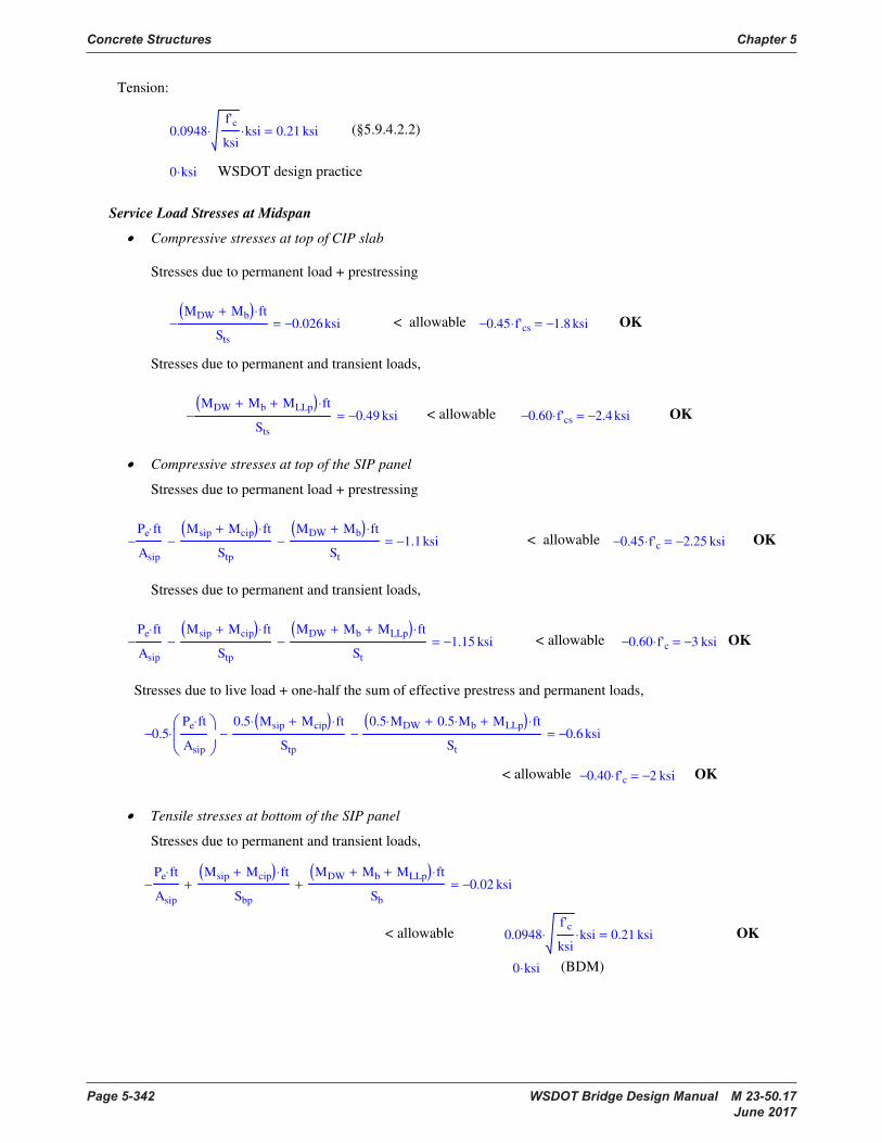
Concrete Structures Chapter 5
Page 5-342 WSDOT Bridge Design Manual M 23-50.17 June 2017
Tension:
0.0948f'c
ksi⋅ ksi⋅ 0.21 ksi= (§5.9.4.2.2)
0 ksi⋅ WSDOT design practice
Service Load Stresses at Midspan
Compressive stresses at top of CIP slab•
Stresses due to permanent load + prestressing
MDW Mb+( ) ft⋅
Sts
− 0.026− ksi= < allowable 0.45− f'cs⋅ 1.8− ksi= OK
Stresses due to permanent and transient loads,
MDW Mb+ MLLp+( ) ft⋅
Sts
− 0.49− ksi= < allowable 0.60− f'cs⋅ 2.4− ksi= OK
Compressive stresses at top of the SIP panel•
Stresses due to permanent load + prestressing
Pe ft⋅
Asip
−
Msip Mcip+( ) ft⋅
Stp
−
MDW Mb+( ) ft⋅
St
− 1.1− ksi= < allowable 0.45− f'c⋅ 2.25− ksi= OK
Stresses due to permanent and transient loads,
Pe ft⋅
Asip
−
Msip Mcip+( ) ft⋅
Stp
−
MDW Mb+ MLLp+( ) ft⋅
St
− 1.15− ksi= < allowable 0.60− f'c⋅ 3− ksi= OK
Stresses due to live load + one-half the sum of effective prestress and permanent loads,
0.5−
Pe ft⋅
Asip
⋅
0.5 Msip Mcip+( )⋅ ft⋅
Stp
−
0.5 MDW⋅ 0.5 Mb⋅+ MLLp+( ) ft⋅
St
− 0.6− ksi=
< allowable 0.40− f'c⋅ 2− ksi= OK
Tensile stresses at bottom of the SIP panel•
Stresses due to permanent and transient loads,
Pe ft⋅
Asip
−
Msip Mcip+( ) ft⋅
Sbp
+
MDW Mb+ MLLp+( ) ft⋅
Sb
+ 0.02− ksi=
< allowable 0.0948f'c
ksi⋅ ksi⋅ 0.21 ksi= OK
0 ksi⋅ (BDM)
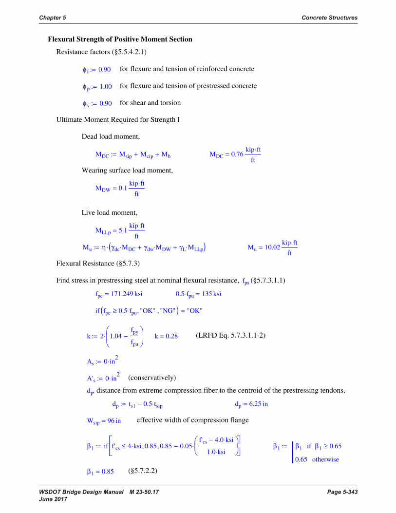
Chapter 5 Concrete Structures
WSDOT Bridge Design Manual M 23-50.17 Page 5-343 June 2017
Flexural Strength of Positive Moment Section
Resistance factors (§5.5.4.2.1)
φ f 0.90:= for flexure and tension of reinforced concrete
φp 1.00:= for flexure and tension of prestressed concrete
φv 0.90:= for shear and torsion
Ultimate Moment Required for Strength I
Dead load moment,
MDC Msip Mcip+ Mb+:= MDC 0.76kip ft⋅
ft=
Wearing surface load moment,
MDW 0.1kip ft⋅
ft=
Live load moment,
MLLp 5.1kip ft⋅
ft=
Mu η γdc MDC⋅ γdw MDW⋅+ γL MLLp⋅+( )⋅:= Mu 10.02kip ft⋅
ft=
Flexural Resistance (§5.7.3)
Find stress in prestressing steel at nominal flexural resistance, fps (§5.7.3.1.1)
fpe 171.249 ksi= 0.5 fpu⋅ 135 ksi=
if fpe 0.5 fpu⋅≥ "OK", "NG",( ) "OK"=
k 2 1.04fpy
fpu
−
⋅:= k 0.28= (LRFD Eq. 5.7.3.1.1-2)
As 0 in2
⋅:=
A's 0 in2
⋅:= (conservatively)
dp, distance from extreme compression fiber to the centroid of the prestressing tendons,
dp ts1 0.5 tsip⋅−:= dp 6.25 in=
Wsip 96 in= effective width of compression flange
β1 if f'cs 4 ksi⋅≤ 0.85, 0.85 0.05f'cs 4.0 ksi⋅−
1.0 ksi⋅
⋅−,
:= β1 β1 β1 0.65≥if
0.65 otherwise
:=
β1 0.85= (§5.7.2.2)

Concrete Structures Chapter 5
Page 5-344 WSDOT Bridge Design Manual M 23-50.17 June 2017
Assume rectangular section,
cAps fpu⋅
0.85 f'cs⋅ β1⋅ Wsip⋅ k Aps⋅
fpu
dp
⋅+
:= c 1.47 in=
Stress in prestressing steel at nominal flexural resistance, fps (§5.7.3.1.1),
fps fpu 1 kc
dp
⋅−
⋅:= fps 252.24 ksi=
Check stress in prestressing steel according to available development length, ld
Available development length at midspan of the SIP panel,
ld 0.5 Lsip⋅:= ld 3.17 ft=
rearranging LRFD eq. 5.11.4.1-1
fpsld
ld
1.6 db⋅
ksi⋅2
3fpe⋅+:= fpsld 177.57 ksi= (may be too conservative)
fps min fps fpsld( )( ):= fps 177.57 ksi=
Flexural Resistance (§5.7.3.2.2 & 5.7.3.2.2),
a β1 c⋅:= a 1.25 in= Aps 1.615 in2
= per panel
Mn Aps fps⋅ dp
a
2−
⋅:=
Mn 134.4kip ft⋅=
Mr φp Mn⋅:= Mr 134.4 kip ft⋅= per panel
Mr
Mr
Wsip
:= Mr 16.81kip ft⋅
ft= per ft
Mu Mr≤ 1= OK where Mu 10.02kip ft⋅
ft=
Limits of Reinforcement
Minimum Reinforcement (§5.7.3.3.2)
Compressive stress in concrete due to effective prestress force (after all losses) at midspan
fpeA
Pe ft⋅
Asip
:= fpeA 0.82 ksi= (compression)
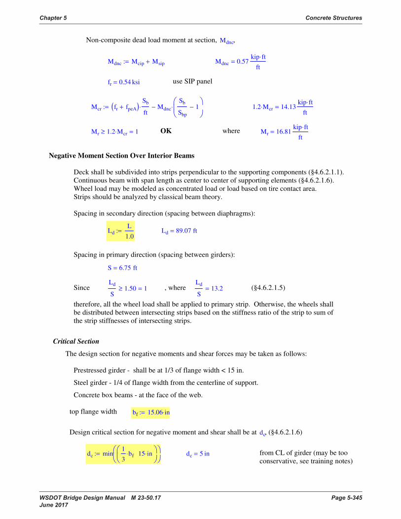
Chapter 5 Concrete Structures
WSDOT Bridge Design Manual M 23-50.17 Page 5-345 June 2017
Non-composite dead load moment at section, Mdnc,
Mdnc Mcip Msip+:= Mdnc 0.57kip ft⋅
ft=
fr 0.54 ksi= use SIP panel
Mcr fr fpeA+( )Sb
ft⋅ Mdnc
Sb
Sbp
1−
⋅−:= 1.2 Mcr⋅ 14.13kip ft⋅
ft=
Mr 1.2 Mcr⋅≥ 1= OK where Mr 16.81kip ft⋅
ft=
Negative Moment Section Over Interior Beams
Deck shall be subdivided into strips perpendicular to the supporting components (§4.6.2.1.1).
Continuous beam with span length as center to center of supporting elements (§4.6.2.1.6).
Wheel load may be modeled as concentrated load or load based on tire contact area.
Strips should be analyzed by classical beam theory.
Spacing in secondary direction (spacing between diaphragms):
Ld
L
1.0:= Ld 89.07 ft=
Spacing in primary direction (spacing between girders):
S 6.75 ft=
SinceLd
S1.50≥ 1= , where
Ld
S13.2= (§4.6.2.1.5)
therefore, all the wheel load shall be applied to primary strip. Otherwise, the wheels shall
be distributed between intersecting strips based on the stiffness ratio of the strip to sum of
the strip stiffnesses of intersecting strips.
Critical Section
The design section for negative moments and shear forces may be taken as follows:
Prestressed girder - shall be at 1/3 of flange width < 15 in.
Steel girder - 1/4 of flange width from the centerline of support.
Concrete box beams - at the face of the web.
top flange width bf 15.06 in⋅:=
Design critical section for negative moment and shear shall be at dc, (§4.6.2.1.6)
dc min1
3bf⋅ 15 in⋅
:= dc 5 in= from CL of girder (may be too
conservative, see training notes)
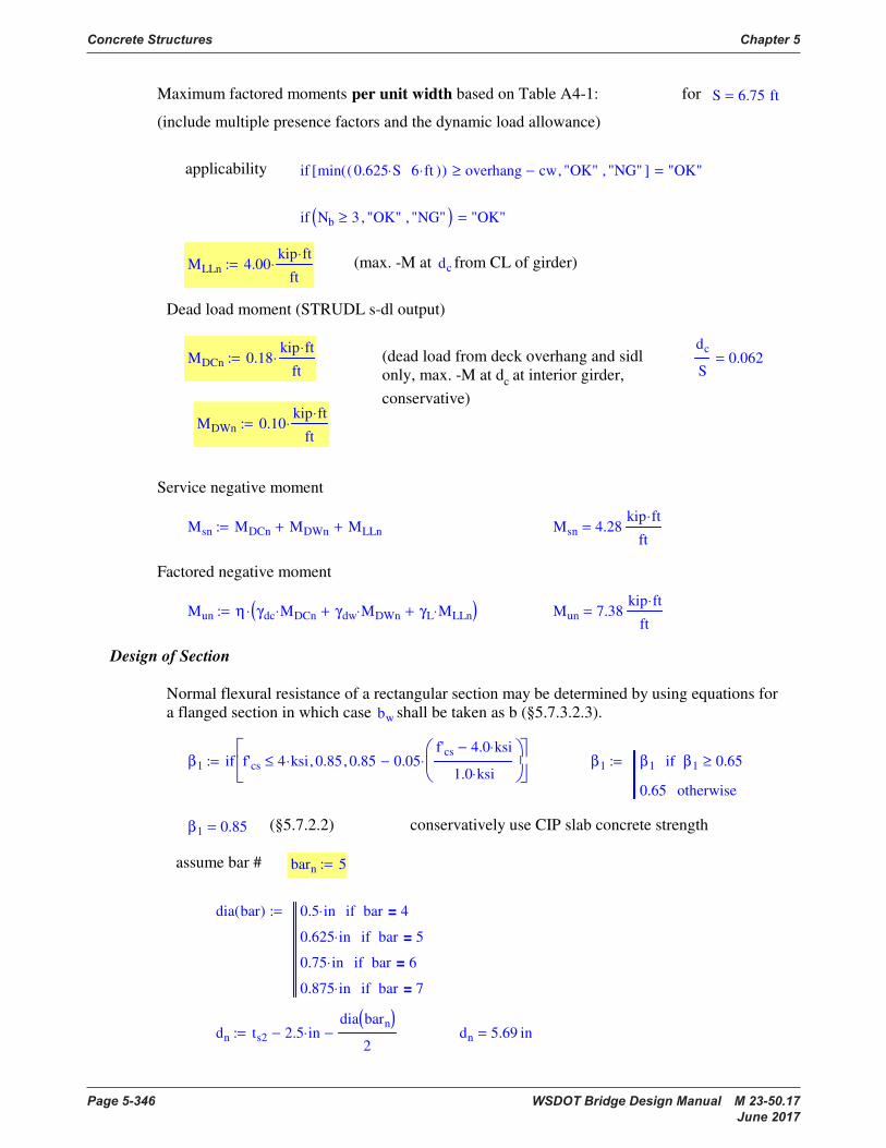
Concrete Structures Chapter 5
Page 5-346 WSDOT Bridge Design Manual M 23-50.17 June 2017
Maximum factored moments per unit width based on Table A4-1: for S 6.75 ft=
(include multiple presence factors and the dynamic load allowance)
applicability if min 0.625 S⋅ 6 ft⋅( )( ) overhang cw−≥ "OK", "NG",[ ] "OK"=
if Nb 3≥ "OK", "NG",( ) "OK"=
MLLn 4.00kip ft⋅
ft⋅:= (max. -M at dc from CL of girder)
Dead load moment (STRUDL s-dl output)
MDCn 0.18kip ft⋅
ft⋅:= (dead load from deck overhang and sidl
only, max. -M at dc at interior girder,
conservative)
dc
S0.062=
MDWn 0.10kip ft⋅
ft⋅:=
Service negative moment
Msn MDCn MDWn+ MLLn+:= Msn 4.28kip ft⋅
ft=
Factored negative moment
Mun η γdc MDCn⋅ γdw MDWn⋅+ γL MLLn⋅+( )⋅:= Mun 7.38kip ft⋅
ft=
Design of Section
Normal flexural resistance of a rectangular section may be determined by using equations for
a flanged section in which case bw shall be taken as b (§5.7.3.2.3).
β1 if f'cs 4 ksi⋅≤ 0.85, 0.85 0.05f'cs 4.0 ksi⋅−
1.0 ksi⋅
⋅−,
:= β1 β1 β1 0.65≥if
0.65 otherwise
:=
β1 0.85= (§5.7.2.2) conservatively use CIP slab concrete strength
assume bar # barn 5:=
dia bar( ) 0.5 in⋅ bar 4=if
0.625 in⋅ bar 5=if
0.75 in⋅ bar 6=if
0.875 in⋅ bar 7=if
:=
dn ts2 2.5 in⋅−
dia barn( )
2−:= dn 5.69 in=

Chapter 5 Concrete Structures
WSDOT Bridge Design Manual M 23-50.17 Page 5-347 June 2017
As
0.85 f'cs⋅ ft⋅
fy
dn dn2 2 Mun⋅ ft⋅
0.85 φ f⋅ f'cs⋅ ft⋅
−−
⋅:= As 0.3 in2
= per ft
use (top-transverse) bar # barn 5= sn 9 in⋅:=
Ab bar( ) 0.20 in2
⋅ bar 4=if
0.31 in2
⋅ bar 5=if
0.44 in2
⋅ bar 6=if
0.60 in2
⋅ bar 7=if
:=
Asn Ab barn( )1 ft⋅
sn
⋅:= Asn 0.41 in2
= per ft
Maximum Reinforcement (§5.7.3.3.1)
The max. amount of prestressed and non-prestressed reinforcement shall be such that
where de dn:=
cAsn fy⋅
0.85 β1⋅ f'cs⋅ 1⋅ ft⋅
:= c 0.72 in=
ifc
de
0.42≤ "OK", "NG",
"OK"=c
de
0.126=
The section is not over-reinforced. Over-reinforced reinforced concrete sections shall
not be permitted.
Minimum Reinforcement (§5.7.3.3.2)
frs 0.24f'cs
ksi⋅ ksi⋅:= frs 0.48 ksi= use SIP panel concrete strength
nEs
Ecs
:= n 6.866= n max ceil n 0.495−( )( ) 6[ ][ ]:=
n 7= set n 7= (round to nearest integer, §5.7.1, not less than 6)
n 1−( )Asn 2.48 in2
=
Agc ts2 ft⋅:= Agc 102 in2
=
ds 2.5in 0.625 in⋅+ 0.5 0.75⋅ in⋅+:= c.g. of reinforcement to top of slab ds 3.5 in=
Yts
Agc 0.5⋅ ts2⋅ n 1−( ) Asn⋅ ds⋅+
Agc n 1−( ) Asn⋅+
:= Yts 4.23 in=
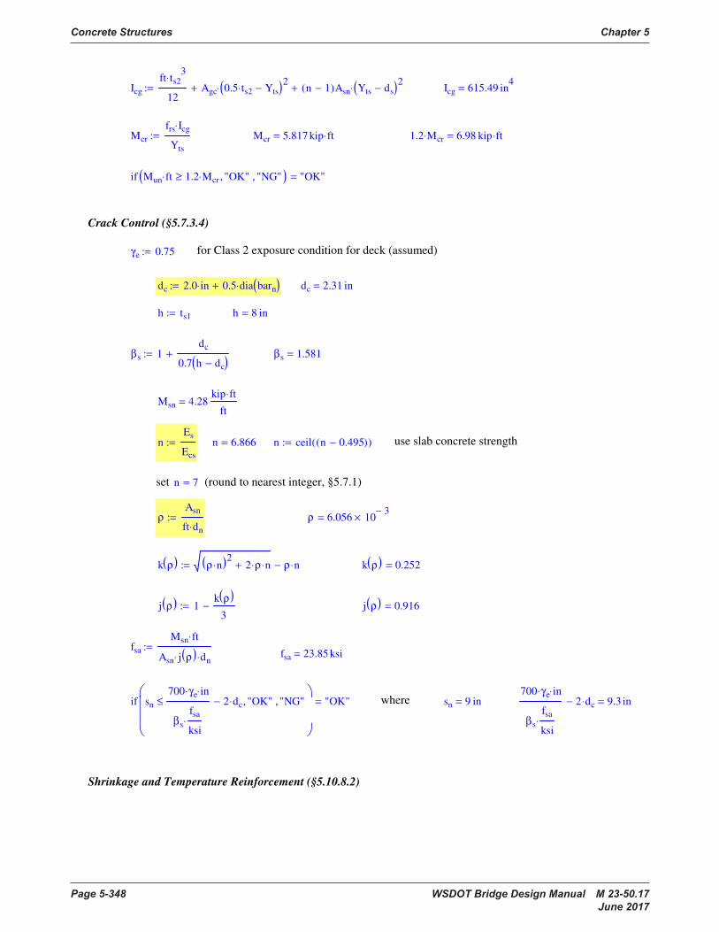
Concrete Structures Chapter 5
Page 5-348 WSDOT Bridge Design Manual M 23-50.17 June 2017
Icg
ft ts23
⋅
12Agc 0.5 ts2⋅ Yts−( )
2⋅+ n 1−( )Asn Yts ds−( )
2⋅+:= Icg 615.49 in
4=
Mcr
frs Icg⋅
Yts
:= Mcr 5.817 kip ft⋅= 1.2 Mcr⋅ 6.98 kip ft⋅=
if Mun ft⋅ 1.2 Mcr⋅≥ "OK", "NG",( ) "OK"=
Crack Control (§5.7.3.4)
γe 0.75:= for Class 2 exposure condition for deck (assumed)
dc 2.0 in⋅ 0.5 dia barn( )⋅+:= dc 2.31 in=
h ts1:= h 8 in=
βs 1dc
0.7 h dc−( )+:= βs 1.581=
Msn 4.28kip ft⋅
ft=
nEs
Ecs
:= n 6.866= n ceil n 0.495−( )( ):= use slab concrete strength
set n 7= (round to nearest integer, §5.7.1)
ρ
Asn
ft dn⋅
:= ρ 6.056 103−
×=
k ρ( ) ρ n⋅( )2
2 ρ⋅ n⋅+ ρ n⋅−:= k ρ( ) 0.252=
j ρ( ) 1k ρ( )
3−:= j ρ( ) 0.916=
fsa
Msn ft⋅
Asn j ρ( )⋅ dn⋅
:=fsa 23.85 ksi=
if sn
700 γe⋅ in⋅
βs
fsa
ksi⋅
2 dc⋅−≤ "OK", "NG",
"OK"= where sn 9 in=
700 γe⋅ in⋅
βs
fsa
ksi⋅
2 dc⋅− 9.3 in=
Shrinkage and Temperature Reinforcement (§5.10.8.2)
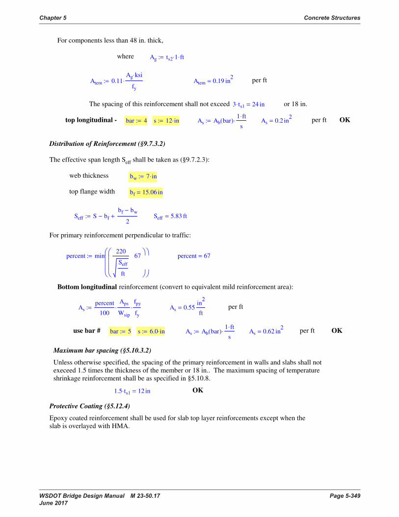
Chapter 5 Concrete Structures
WSDOT Bridge Design Manual M 23-50.17 Page 5-349 June 2017
For components less than 48 in. thick,
where Ag ts2 1⋅ ft⋅:=
Atem 0.11Ag ksi⋅
fy
⋅:= Atem 0.19 in2
= per ft
The spacing of this reinforcement shall not exceed 3 ts1⋅ 24 in= or 18 in.
top longitudinal - bar 4:= s 12 in⋅:= As Ab bar( )1 ft⋅
s⋅:= As 0.2 in
2= per ft OK
Distribution of Reinforcement (§9.7.3.2)
The effective span length Seff shall be taken as (§9.7.2.3):
web thickness bw 7 in⋅:=
top flange width bf 15.06 in=
Seff S bf−
bf bw−
2+:= Seff 5.83 ft=
For primary reinforcement perpendicular to traffic:
percent min220
Seff
ft
67
:= percent 67=
Bottom longitudinal reinforcement (convert to equivalent mild reinforcement area):
As
percent
100
Aps
Wsip
⋅
fpy
fy
⋅:= As 0.55in
2
ft= per ft
use bar # bar 5:= s 6.0 in⋅:= As Ab bar( )1 ft⋅
s⋅:= As 0.62 in
2= per ft OK
Maximum bar spacing (§5.10.3.2)
Unless otherwise specified, the spacing of the primary reinforcement in walls and slabs shall not
execeed 1.5 times the thickness of the member or 18 in.. The maximum spacing of temperature
shrinkage reinforcement shall be as specified in §5.10.8.
1.5 ts1⋅ 12 in= OK
Protective Coating (§5.12.4)
Epoxy coated reinforcement shall be used for slab top layer reinforcements except when the
slab is overlayed with HMA.

Page 5-350 WSDOT Bridge Design Manual M 23-50.17 June 2017
Appendix 5-B8 W35DG Deck Bulb Tee 48" Wide
:=
:=
:=
:=
:=
:=
Prestressing Steel (low-relaxation)
=
⋅:=
Rupture Modulus
= ρ
⋅
⋅:=
= ρ
⋅
⋅:=
µ := :=
ρ := :=
Precast Concrete
:=
:=Flexural Design Example, LRFD 2005
:=W35DG Deck Bulb Tee, 48" Wide

Chapter 5 Concrete Structures
WSDOT Bridge Design Manual M 23-50.17 Page 5-351 June 2017
DC: Girder self-weight
=
−( ):=
=
:=
:=
:=
:=
:=
Section Properties
:=
Gross area (used for dead weight calculations)
:=
Section depth
:= :=
Top flange width (i.e. girder spacing)
:=
Span Length (bearing to bearing)
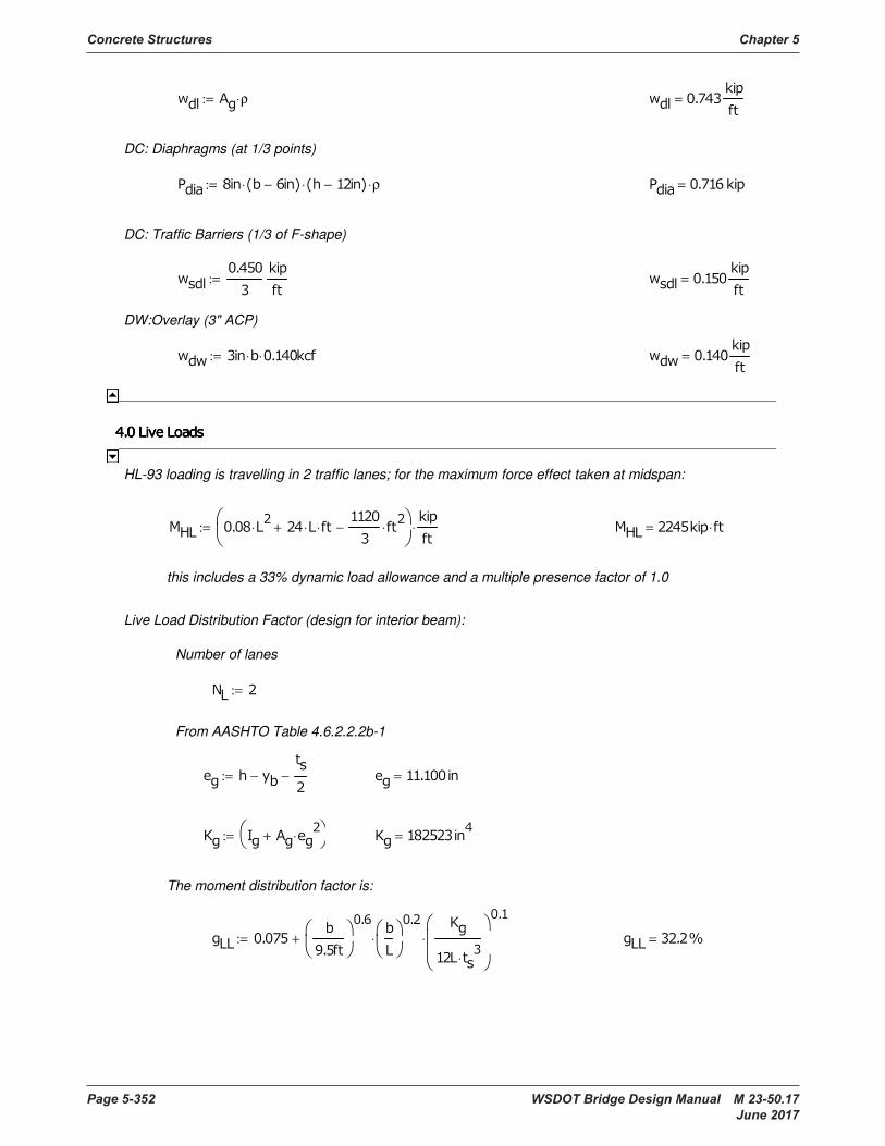
Concrete Structures Chapter 5
Page 5-352 WSDOT Bridge Design Manual M 23-50.17 June 2017
=
⋅
⋅
⋅+:=
The moment distribution factor is:
=
⋅+
:=
= −
−:=
From AASHTO Table 4.6.2.2.2b-1
:=
Number of lanes
Live Load Distribution Factor (design for interior beam):
this includes a 33% dynamic load allowance and a multiple presence factor of 1.0
⋅=
⋅ ⋅ ⋅+
⋅−
⋅:=
HL-93 loading is travelling in 2 traffic lanes; for the maximum force effect taken at midspan:
= ⋅ ⋅ :=
DW:Overlay (3" ACP)
=
:=
DC: Traffic Barriers (1/3 of F-shape)
= − ⋅ − ⋅ ρ⋅:=
DC: Diaphragms (at 1/3 points)
= ρ⋅:=

Chapter 5 Concrete Structures
WSDOT Bridge Design Manual M 23-50.17 Page 5-353 June 2017
⋅= ⋅ ⋅+ +:=
Strength I
⋅= + ⋅+:=
Service III
⋅= + +:=
Service I
Conservatively, the design moment will be the maximum dead and live load moments at midspan
⋅= ⋅:=
LL+I; Live load effects
⋅=
⋅:=
DW; Overlay load effects
⋅=(at 0.4L point)
⋅
:=
Dead load moment at harping point (for stress at release)
⋅= +:=
⋅=
⋅
⋅+:=
⋅=
⋅:=
DC; Component load effects
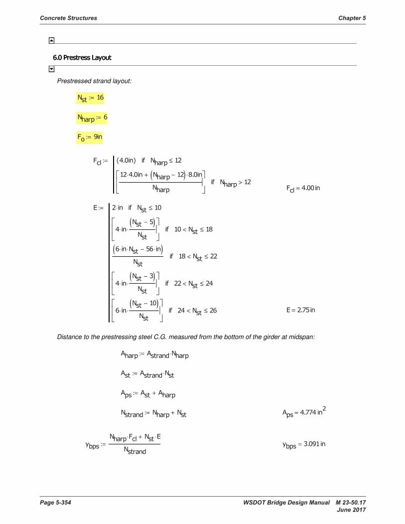
Concrete Structures Chapter 5
Page 5-354 WSDOT Bridge Design Manual M 23-50.17 June 2017
=
⋅ ⋅+
:=
= +:=
+:=
⋅:=
⋅:=
Distance to the prestressing steel C.G. measured from the bottom of the girder at midspan:
=
⋅ ≤
⋅
−( )
⋅
< ≤
⋅ ⋅ ⋅−( )
< ≤
⋅
−( )
⋅
< ≤
⋅
−( )
⋅
< ≤
:=
=
≤
⋅ −( ) ⋅ +
>
:=
:=
:=
:=
Prestressed strand layout:
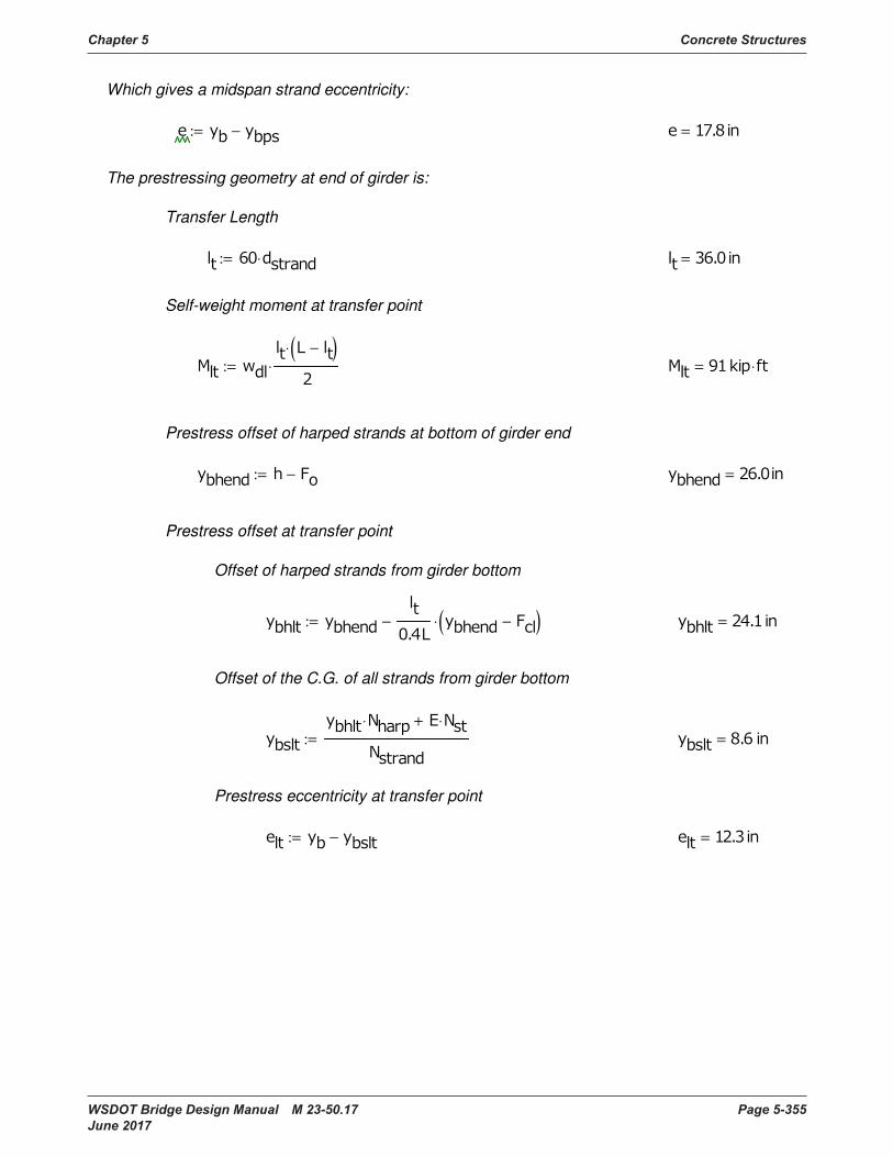
Chapter 5 Concrete Structures
WSDOT Bridge Design Manual M 23-50.17 Page 5-355 June 2017
:
= −:=
Prestress eccentricity at transfer point
=
⋅ ⋅+
:=
Offset of the C.G. of all strands from girder bottom
=
−( )⋅−:=
Offset of harped strands from girder bottom
Prestress offset at transfer point
= −:=
Prestress offset of harped strands at bottom of girder end
⋅=
−( )⋅
⋅:=
Self-weight moment at transfer point
= ⋅:=
Transfer Length
The prestressing geometry at end of girder is:
= −:=
Which gives a midspan strand eccentricity:

Concrete Structures Chapter 5
Page 5-356 WSDOT Bridge Design Manual M 23-50.17 June 2017
∆ =∆ ⋅
−
⋅:=
(days before transfer) :=
Steel Relaxation Losses (for low-relaxation strands)
∆ =∆
⋅:=
=
⋅
+
⋅
−:=
Elastic Shortening Losses
= ⋅ ⋅:=
Estimate of initial PS force after release, Psr :
= ⋅:=
⋅:=
Jacking PS force:
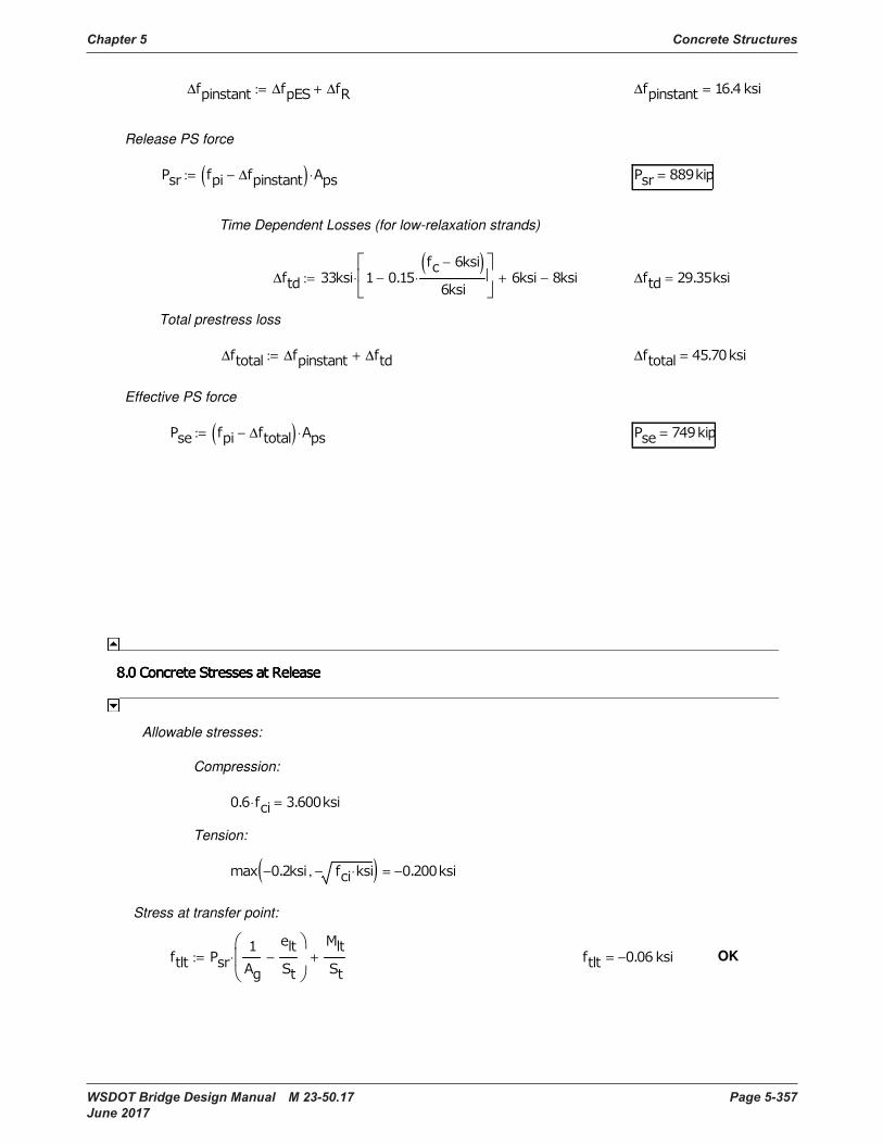
Chapter 5 Concrete Structures
WSDOT Bridge Design Manual M 23-50.17 Page 5-357 June 2017
OK − =
−
⋅
+:=
Stress at transfer point:
− ⋅−,( ) − =
Tension:
⋅ =
Compression:
Allowable stresses:
= ∆−( ) ⋅:=
Effective PS force
∆ =∆ ∆ ∆+:=
Total prestress loss
∆ =∆ −( )
⋅−
⋅ + −:=
Time Dependent Losses (for low-relaxation strands)
= ∆−( ) ⋅:=
Release PS force
∆ =∆ ∆ ∆+:=

Concrete Structures Chapter 5
Page 5-358 WSDOT Bridge Design Manual M 23-50.17 June 2017
(Under half of permanent loads and full live load)
⋅ = (Under full Service I load)
Tension (per BDM):
(Tension check under Service III load)
Concrete stress at midspan:
−
⋅
+
+:= = OK
−
⋅
+
+
⋅
+:= = OK
−
⋅
+:= = OK
+
⋅
−:= = OK
Stress at harp point:
−
⋅
+:= = OK
+
⋅
−:= = OK
Allowable concrete stress at midpsan
Compression; Cases I, II, and III:
⋅ = (Under total dead load)
⋅ =
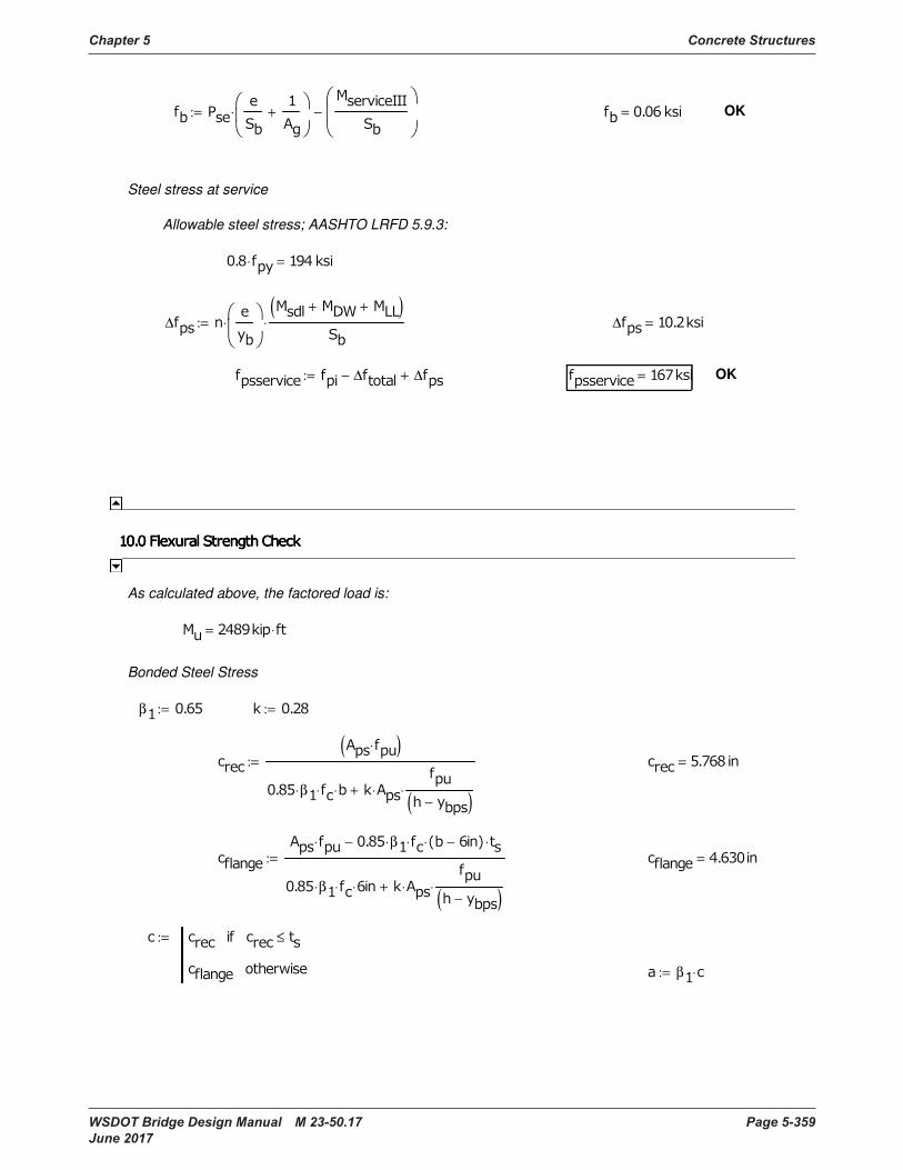
Chapter 5 Concrete Structures
WSDOT Bridge Design Manual M 23-50.17 Page 5-359 June 2017
β ⋅:=
≤
:=
=
⋅ β⋅ ⋅ − ⋅ ⋅−
β⋅ ⋅ ⋅ ⋅
−( )⋅+
:=
=
⋅( )
β⋅ ⋅ ⋅ ⋅
−( )⋅+
:=
:=β :=
Bonded Steel Stress
⋅=
As calculated above, the factored load is:
OK = ∆− ∆+:=
∆ =∆
⋅
+ +( )
⋅:=
⋅ =
Allowable steel stress; AASHTO LRFD 5.9.3:
Steel stress at service
OK =
+
⋅
−:=
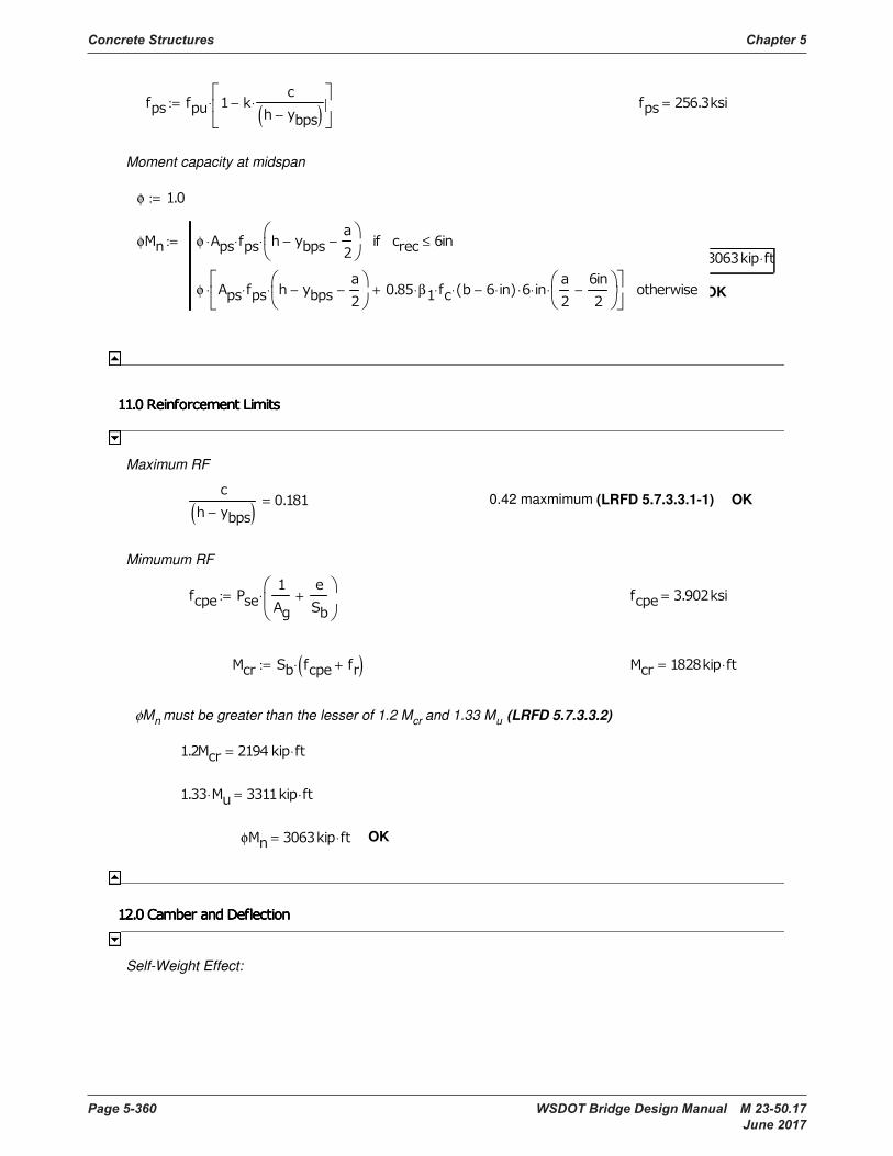
Concrete Structures Chapter 5
Page 5-360 WSDOT Bridge Design Manual M 23-50.17 June 2017
Self-Weight Effect:
OK φ ⋅=
⋅ ⋅=
⋅=
φMn must be greater than the lesser of 1.2 Mcr and 1.33 Mu (LRFD 5.7.3.3.2)
⋅= +( )⋅:=
=
+
⋅:=
Mimumum RF
OK 0.42 maxmimum (LRFD 5.7.3.3.1-1)
−( )=
Maximum RF
OK
φ ⋅=
φ φ ⋅ ⋅ −
−
⋅ ≤
φ ⋅ −
−
⋅ β⋅ ⋅ ⋅− ⋅ ⋅ ⋅
−
⋅+
⋅
:=
φ :=
Moment capacity at midspan
=
−( )⋅−
⋅:=
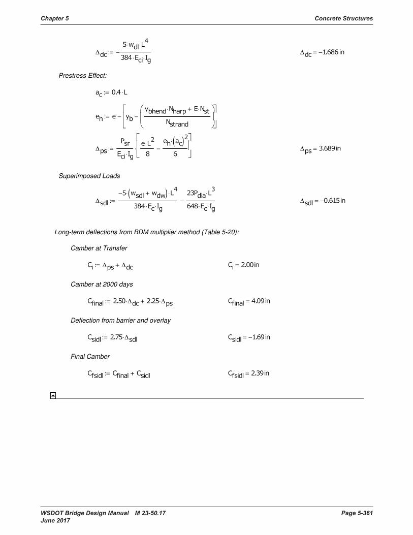
Chapter 5 Concrete Structures
WSDOT Bridge Design Manual M 23-50.17 Page 5-361 June 2017
= +:=
Final Camber
− = ∆⋅:=
Deflection from barrier and overlay
= ∆⋅ ∆⋅+:=
Camber at 2000 days
= ∆ ∆+:=
Camber at Transfer
Long-term deflections from BDM multiplier method (Table 5-20):
∆ − =∆
− +( )⋅
⋅
⋅ ⋅
⋅
⋅ ⋅
−:=
Superimposed Loads
∆ =∆
⋅
⋅
( )
⋅
−
⋅:=
⋅ ⋅+
−
−:=
⋅:=
Prestress Effect:
∆ − =∆
⋅
⋅
⋅ ⋅
−:=

Page 5-362 WSDOT Bridge Design Manual M 23-50.17 June 2017
Prestressed Voided Slab Appendix 5-B9 with Cast-in-Place Topping
Specification
Reference
Girder type: 18 Prelim.Plan, Sh 1
Span Length: L = 58.00 ft C.L. to C.L. Bearing BDM 5.6.2-A
Girder Length: Lg = 58.83 ft End to End BDM fig. 5-A-XX
Bridge Width: W = 42.75 ft Deck Width Prelim.Plan, Sh 1
Number of Lanes 2 "
Skew Angle: qskew = 0.00 degrees "
Girder Section Properties
Girder Width: b = 4.00 ft = 48.00 in BDM fig. 5-A-XX
Girder Depth: d = 18.00 in = 1.50 ft "
Height h = 23.00 in
Top Flange Thickness ttf = 4.50 in (from top of void to bottom of slab). "
Bottom Flange Thickness tbf = 4.50 in (from bottom of void to bottom of girder). "
hf = td + ttf = 9.50
Width of each Void beachV = 9.00 in "
Net Width of Girder bw = 21.00 in Aactual = 5.25 in2
Number of Voids Nv = 3 Adesign= 5.50 in2 "
Area of Each Void Aeach v = 63.62 in2
"
Void Area: Av = 190.85 in2 Void Perimeter each= 28.27 in "
Area of Girder Ag = 673.15 in2
"
Area of Deck + Leg Ad = 240.00 in2
Area of Comp. Sect. Acomp = 913.15 in2
Number of girders Ng = 10 W/b = 10.69 Prelim.Plan, Sh 2
Wt of barrier wTB = 0.50 k/ft
Thickness of deck td = 5.00 in
Wt of Concrete wc= 0.155 kcp for calculating Ec BDM 5.1.1-D
Wt of Concrete wcd = 0.160 kcp for dead load calculations BDM 3.1.1
Strength of Concrete
Deck fc' = 4.0 ksi BDM 5.1.1-A.1
Final fc' = 8.5 ksi Transfer fci' = 7.0 ksi BDM 5.1.1-A.2
*Modulus of Elasticity (girder), 5871.1 ksi
*Modulus of Elasticity (deck), 4027.6 ksi
*Modulus of Elasticity (transfer), 5328.0
nc = 1.46 ratio for transformed section LRFD 5.7.1
Modulus of Rupture, 0.700 ksi LRFD 5.4.2.6
1.08 ksi "
Poisson's ratio = m = 0.2 LRFD 5.4.2.5
BDM 5.1.1-D
LRFD 5.4.2.4-1
General Input AASHTO LRFD Specifications
Modulus of Rupture to calculate min.
reinforcement,
Prestressed Precast Flat Slab
Prestressed Voided Slab with Cast-in-Place Topping
== '5.1
33000ci
fc
wci
E
== '24.0c
fr
f
== '5.1
33000c
fc
wc
E
== '5.1
33000c
fc
wc
E
== '37.0min c
frMcr
f
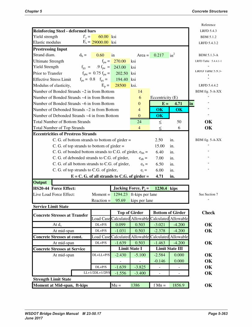
Chapter 5 Concrete Structures
WSDOT Bridge Design Manual M 23-50.17 Page 5-363 June 2017
Reference
Reinforcing Steel - deformed bars LRFD 5.4.3
Yield strength f'y = 60.00 ksi BDM 5.1.2
Elastic modulus Es = 29000.00 ksi LRFD 5.4.3.2
Prestressing Input
Strand diam. db = 0.60 in Area = 0.217 in2 BDM 5.1.3-A
Ultimate Strength fpu = 270.00 ksi LRFD Table 5.4.4.1-1
Yield Strength fpy = .9 fpu = 243.00 ksi "
Prior to Transfer fpbt = 0.75 fpu = 202.50 ksiLRFD Table 5.9.3-
1
Effective Stress Limit fpe = 0.8 fpy = 194.40 ksi "
Modulus of elasticity, Ep = 28500 ksi. LRFD 5.4.4.2
Number of Bonded Strands ~2 in from Bottom 14 BDM fig. 5-A-XX
Number of Bonded Strands ~4 in from Bottom 6 Eccentricity (E) "
Number of Bonded Strands ~6 in from Bottom 0 E = 4.71 in "
Number of Debonded Strands ~2 in from Bottom 4 OK OK "
Number of Debonded Strands ~4 in from Bottom 0 OK "
Total Number of Bottom Strands 24 50 OK
Total Number of Top Strands 4 6 OK
Eccentricities of Prestress Strands
C. G. of bottom strands to bottom of girder = 2.50 in. BDM fig. 5-A-XX
C. G. of top strands to bottom of girder = 15.00 in. "
C. G. of bonded bottom strands to C.G. of girder, ebb = 6.40 in. "
C. G. of debonded strands to C.G. of girder, edb = 7.00 in. "
C. G. of all bottom strands to C.G. of girder, eb = 6.50 in. "
C. G. of top strands to C.G. of girder, et = 6.00 in. "
E = C. G. of all strands to C.G. of girder = 4.71 in.
Output
HS20-44 Force Effect: Jacking Force, Pj = 1230.4 kips
Live Load Force Effect: Moment = 1294.23 ft-kips per lane See Section 7
Reaction = 95.69 kips per lane "
Service Limit State
Top of Girder Bottom of Girder Check
Load Case Calculated Allowable Calculated Allowable
At dv DL+P/S 0.099 0.503 -3.021 -4.200 OK
At mid-span DL+P/S -1.031 0.503 -2.378 -4.200 OK
Concrete Stresses at const. Load Case Calculated Allowable Calculated Allowable
At mid-span DL+P/S -1.639 0.503 -1.463 -4.200 OK
Concrete Stresses at Service
At mid-span DL+LL+P/S -2.430 -5.100 -2.584 0.000 OK
- - -0.146 0.000 OK
DL+P/S -1.639 -3.825 - - OK
-1.556 -3.400 - - OK
Strength Limit State
Moment at Mid-span, ft-kips Mu = 1386 f Mn = 1856.9 OK
Limit State I Limit State III
LL+1/2DL+1/2P/S
Concrete Stresses at Transfer
≤
≤

Concrete Structures Chapter 5
Page 5-364 WSDOT Bridge Design Manual M 23-50.17 June 2017
Table of ContentsContent
1 Structure:
2 Live load
HL-93
3 Material Properties
4 Allowable Concrete Stresses at Service Limit State
5 Computation of Section Properties
6 Limit State
7 Vehicular Live Load
8 Computation of Stresses
9 Approximate Evaluation of Pre-Stress Losses
10 Stresses at Service Limit State
Stresses After Elastic Shortening and Relaxation (Table 10-1)
Stresses at transfer
Load combinations and load factors
Concrete Stresses Due to LL+IM (Composite Section) (Table 8-12)
Table 7-3: Distributed Live Loads
Stresses Due to Weight of Girder (Table 8-1 thru 8-5)
Concrete Stresses Due to Traffic Barrier (Table 8-6 thru 8-8)
Single Span Bridge
Stresses After Losses (Noncomposite) (Table 10-2)
Summary of Stresses at Service Limit State (Table 10-3)
Tensile Stress Limit in Areas Without Bonded Reinforcement (at dv)
Concrete
Tensile stress limit
Maximum live load force effect
Service limit state
Loss due to Strand Relaxation
Tensile Stress Limit at Service - III Load Combination
Loss due to elastic shortening
Compressive Stress Limit at Service - I Load Combination
Table 7-2: Summary of Live Load Distribution Factors:
Summary of Stresses at dv (Table 8-13)
Time Dependent Losses
Summary of Stresses at Mid-Span (Table 8-14)
Girder and Composite Section Properties (Table 5-1)
Compressive stress limits after all losses
Design vehicular live load
Dynamic load allowance (Impact, IM)
Distribution of Live Load, Dfi (Beam Slab Bridges)
Shear Distribution Factor
Transformed Section Properties (Table 5-2)
Concrete Stresses Due to Concrete Deck and Legs (Table 8-9 thru 8-11)
Chapter 5 Concrete Structures
WSDOT Bridge Design Manual M 23-50.17 Page 5-365 June 2017
11 Strength Limit State
NG Mu No Check
OK for rectangular section
OK developed
12 Shear Design
fpo
b and q
OK for Min. Transverse Reinf.
OK for Longitudinal Reinforcement
13 Deflection and Camber
Creep Coefficients (Table 13-1)
Final Deflection Due to All Loads and Creep OK for deflection
Minimum reinforcement
Deflection due to prestressing forces at Transfer
Deflection due to weight of Girder
Required shear strength
References
Maximum spacing of shear reinforcement
Nominal flexural resistance
Flexural forces
Resistance factors
Factored shear force
Shear strength
Effective Web Width, bv, and Effective Shear Depth, dv
Determination of
Shear Stress Ratio
Longitudinal Strain (Flexural Tension)
Component of Prestressing Force in Direction of Shear Force, Vp
Factored moment
Minimum shear reinforcement
Longitudinal reinforcement
Design procedure
Flexural resistance
Development of prestressing strand
Time Verses Deflection Curve (fig. 13-1)
Deflection due to weight of Traffic Barrier TB
Deflection due to weight of Deck and Legs
Deflection (Camber) at transfer, Ci
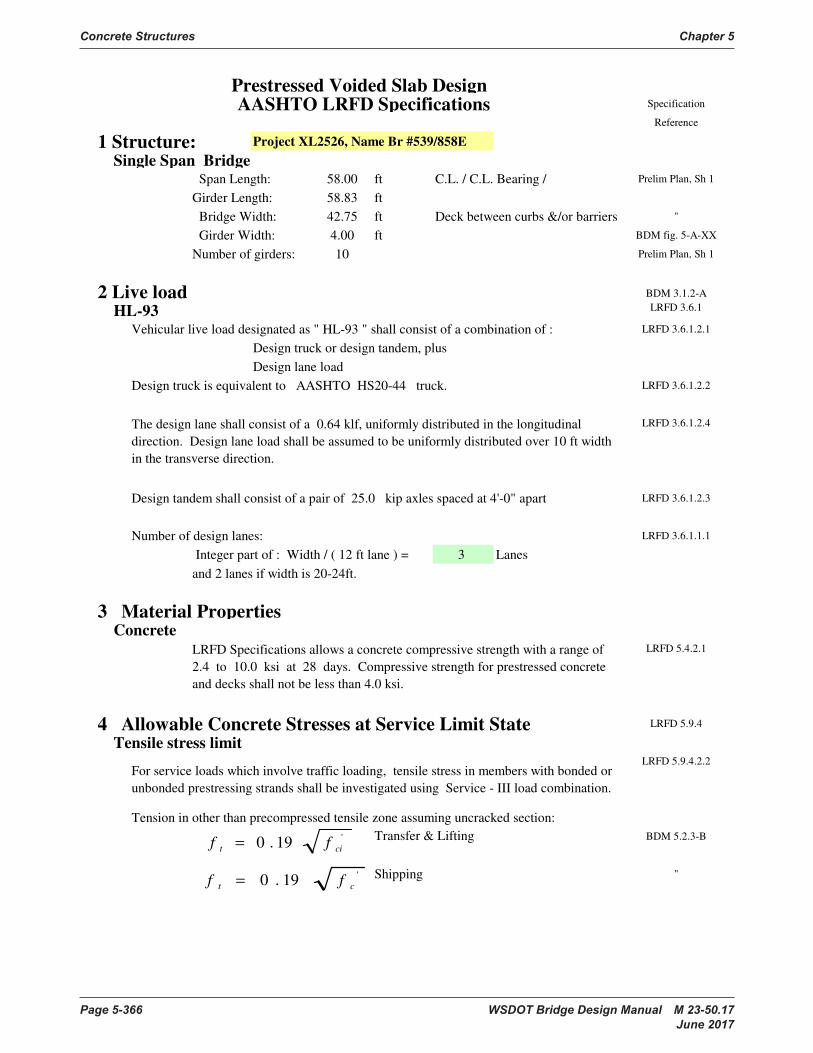
Concrete Structures Chapter 5
Page 5-366 WSDOT Bridge Design Manual M 23-50.17 June 2017
Prestressed Voided Slab Design AASHTO LRFD Specifications Specification
Reference
1 Structure: Project XL2526, Name Br #539/858E
Single Span Bridge Span Length: 58.00 ft C.L. / C.L. Bearing / Prelim Plan, Sh 1
Girder Length: 58.83 ft
Bridge Width: 42.75 ft Deck between curbs &/or barriers "
Girder Width: 4.00 ft BDM fig. 5-A-XX
Number of girders: 10 Prelim Plan, Sh 1
2 Live loadHL-93
Vehicular live load designated as " HL-93 " shall consist of a combination of : LRFD 3.6.1.2.1
Design truck or design tandem, plus
Design lane load
Design truck is equivalent to AASHTO HS20-44 truck. LRFD 3.6.1.2.2
LRFD 3.6.1.2.4
Design tandem shall consist of a pair of 25.0 kip axles spaced at 4'-0" apart LRFD 3.6.1.2.3
Number of design lanes: LRFD 3.6.1.1.1
Integer part of : Width / ( 12 ft lane ) = 3 Lanes
and 2 lanes if width is 20-24ft.
3 Material PropertiesConcrete
LRFD 5.4.2.1
4 Allowable Concrete Stresses at Service Limit State LRFD 5.9.4
Tensile stress limitLRFD 5.9.4.2.2
Tension in other than precompressed tensile zone assuming uncracked section:
BDM 5.2.3-B
Shipping "
LRFD Specifications allows a concrete compressive strength with a range of
2.4 to 10.0 ksi at 28 days. Compressive strength for prestressed concrete
and decks shall not be less than 4.0 ksi.
BDM 3.1.2-A
LRFD 3.6.1
The design lane shall consist of a 0.64 klf, uniformly distributed in the longitudinal
direction. Design lane load shall be assumed to be uniformly distributed over 10 ft width
in the transverse direction.
Transfer & Lifting
For service loads which involve traffic loading, tensile stress in members with bonded or
unbonded prestressing strands shall be investigated using Service - III load combination.
'19.0 cit ff =
'19.0 ct ff =
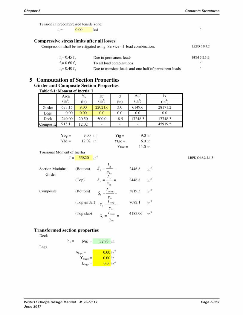
Chapter 5 Concrete Structures
WSDOT Bridge Design Manual M 23-50.17 Page 5-367 June 2017
Tension in precompressed tensile zone:
ft = 0.00 ksi "
Compressive stress limits after all losses Compression shall be investigated using Service - I load combination: LRFD 5.9.4.2
fc= 0.45 f'c Due to permanent loads BDM 5.2.3-B
fc= 0.60 f'c To all load combinations "
fc= 0.40 f'c Due to transient loads and one-half of permanent loads "
5 Computation of Section PropertiesGirder and Composite Section Properties
Table 5-1: Moment of Inertia, I
Area Yb Ix` d Ad2
(in2) (in) (in
4) (in) (in
4)
Girder 673.15 9.00 22021.6 3.0 6149.6
Legs 0.00 0.00 0.0 0.0 0.0
Deck 240.00 20.50 500.0 -8.5 17248.3
Composite 913.1 12.02 - - -
Ybg = 9.00 in Ytg = 9.0 in
Ybc = 12.02 in Ytgc = 6.0 in
Ytsc = 11.0 in
Torsional Moment of Inertia
J = 55820 in4 LRFD C4.6.2.2.1-3
Section Modulus: (Bottom) 2446.8 in3
Girder
(Top) 2446.8 in3
Composite (Bottom) 3819.5 in3
(Top girder) 7682.1 in3
(Top slab) 4183.06 in3
Transformed section propertiesDeck
be = b/nc = 32.93 in
Legs
Alege = 0.00 in2
Yblege = 0.00 in
Ixlege = 0.0 in4
Ix
28171.2
(in4)
17748.3
45919.5
0.0
==
bg
g
by
IS
==
tg
g
ty
IS
==
bc
comp
by
IS
==
tgc
comp
ty
IS
==
tsc
comp
ty
IS
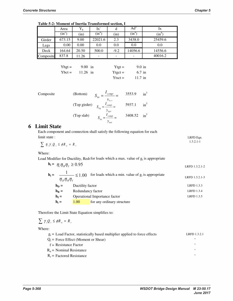
Concrete Structures Chapter 5
Page 5-368 WSDOT Bridge Design Manual M 23-50.17 June 2017
Table 5-2: Moment of Inertia Transformed section, I
Area Yb Ix` d Ad2
(in2) (in) (in
4) (in) (in
4)
Girder 673.15 9.00 22021.6 2.3 3438.0
Legs 0.00 0.00 0.0 0.0 0.0
Deck 164.64 20.50 500.0 -9.2 14056.6
Composite 837.8 11.26 - - -
Ybgt = 9.00 in Ytgt = 9.0 in
Ybct = 11.26 in Ytgct = 6.7 in
Ytsct = 11.7 in
Composite (Bottom) 3553.9 in3
(Top girder) 5937.1 in3
(Top slab) 3408.52 in3
6 Limit StateEach component and connection shall satisfy the following equation for each
limit state :
Where:
Load Modifier for Ductility, Redundancy, & Operational Importancefor loads which a max. value of gi is appropriate
hi =
hi = for loads which a min. value of gi is appropriate
hD = Ductility factor LRFD 1.3.3
hR = Redundancy factor LRFD 1.3.4
hI = Operational Importance factor LRFD 1.3.5
hi = 1.00 for any ordinary structure
Therefore the Limit State Equation simplifies to:
Where:
gi = Load Factor, statistically based multiplier applied to force effects LRFD 1.3.2.1
Qi = Force Effect (Moment or Shear) "
f = "
Rn = "
Rr = Factored Resistance "
Ix
14556.6
40016.2
Nominal Resistance
Resistance Factor
LRFD Eqn.
1.3.2.1-1
(in4)
25459.6
LRFD 1.3.2.1-2
LRFD 1.3.2.1-3
0.0
rniii RRQ =≤ φγη
95.0≥IRi ηηη
00.11
≤
IRD ηηη
rnii RRQ =≤ φγ
==
tsct
compt
ttsy
IS
==
bct
compt
bty
IS
==
tgct
compt
ttgy
IS
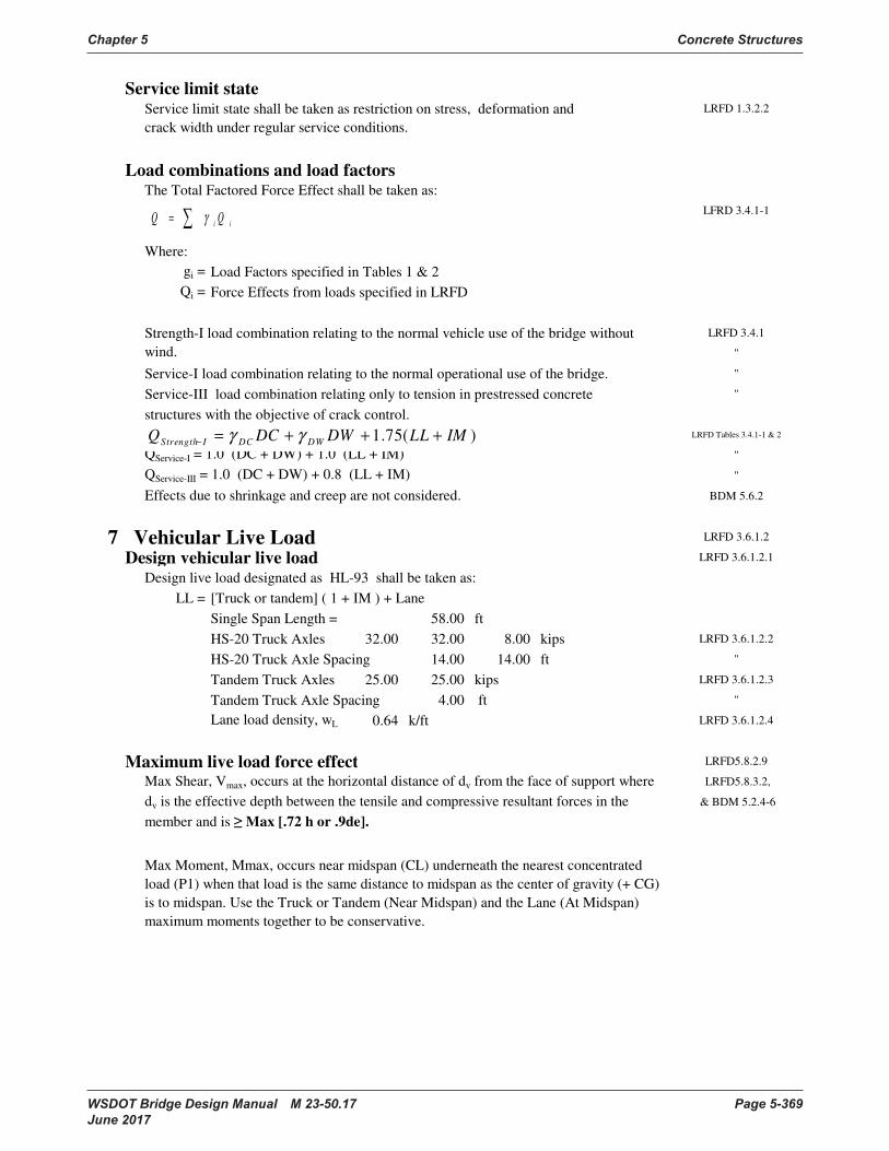
Chapter 5 Concrete Structures
WSDOT Bridge Design Manual M 23-50.17 Page 5-369 June 2017
Service limit stateLRFD 1.3.2.2
Load combinations and load factorsThe Total Factored Force Effect shall be taken as:
LFRD 3.4.1-1
Where:
gi = Load Factors specified in Tables 1 & 2
Qi = Force Effects from loads specified in LRFD
LRFD 3.4.1
"
Service-I load combination relating to the normal operational use of the bridge. "
Service-III load combination relating only to tension in prestressed concrete "
structures with the objective of crack control.
LRFD Tables 3.4.1-1 & 2
"
"
BDM 5.6.2
7 Vehicular Live Load LRFD 3.6.1.2
Design vehicular live load LRFD 3.6.1.2.1
Design live load designated as HL-93 shall be taken as:
LL = [Truck or tandem] ( 1 + IM ) + Lane
Single Span Length = 58.00 ft
HS-20 Truck Axles 32.00 32.00 8.00 kips LRFD 3.6.1.2.2
HS-20 Truck Axle Spacing 14.00 14.00 ft "
Tandem Truck Axles 25.00 25.00 kips LRFD 3.6.1.2.3
Tandem Truck Axle Spacing 4.00 ft "
Lane load density, wL = 0.64 k/ft LRFD 3.6.1.2.4
Maximum live load force effect LRFD5.8.2.9
LRFD5.8.3.2,
& BDM 5.2.4-6
Strength-I load combination relating to the normal vehicle use of the bridge without
wind.
Max Moment, Mmax, occurs near midspan (CL) underneath the nearest concentrated
load (P1) when that load is the same distance to midspan as the center of gravity (+ CG)
is to midspan. Use the Truck or Tandem (Near Midspan) and the Lane (At Midspan)
maximum moments together to be conservative.
QService-III = 1.0 (DC + DW) + 0.8 (LL + IM)
Max Shear, Vmax, occurs at the horizontal distance of dv from the face of support where
dv is the effective depth between the tensile and compressive resultant forces in the
member and is Max [.72 h or .9de].
QService-I = 1.0 (DC + DW) + 1.0 (LL + IM)
Effects due to shrinkage and creep are not considered.
Service limit state shall be taken as restriction on stress, deformation and
crack width under regular service conditions.
= ii QQ γ
)(75.1 IMLLDWDCQ DWDCIStrength +++=−
γγ

Concrete Structures Chapter 5
Page 5-370 WSDOT Bridge Design Manual M 23-50.17 June 2017
So the HL-93 Live Load, LL = HS-20 Truck(1+IM)+Lane Load Governs
Near Center line
Mmax = 770.759 ft-kips Corresponding V@Mmax = 25.10 kips
At dv
Vmax = 58.67 kips Corresponding M@Vmax = 82.35 ft-kips LRFD 5.8.3.2
Lane Loading
M@dv = 25.4199 ft-kips Corresponding V@dv = 17.66 kips
M@CL 269.12 ft-kips Corresponding V@CL = 0.00 Kips
Dynamic load allowance (Impact, IM) LRFD 3.6.2.1
The static effect of Design Truck LL shall be increased by the following
percentage : IM = 33% For bridge components (girder) LRFD Table 3.6.2.1-1
At dv 3' 6' 9' At CL
M(LL+IM)= 134.9 279.0 522.5 730.5 1294.2 k-ft
V(LL+IM)= 95.7 92.0 85.2 78.3 32.5 kips
Distribution of Live Load, Dfi (Beam Slab Bridges) LRFD 4.6.2.2
Width of deck is constant LRFD 4.6.2.2.1
"
Beams are parallel "
Beams have approximately the same stiffness "
"
Curvature in plane is less than 12 degree "
X-section is one consistent with one listed in LRFD Table 4.6.2.2.1-1 "
The multiple presence factor shall not be applied in conjunction with approximate LRFD 3.6.1.1.2
load distribution except for exterior beams.
The typical x-section applies to voided and solid slabs w P.T. LRFD Table 4.6.2.2.1-1
the composite deck makes the section significantly connected to act as a unit.
Distribution Factor for Moment Interior Girder, DFMInt LRFD 4.6.2.2.2b
For Multibeam deck bridges within the range of applicability and conditions as
follows, the approximate method of live load distribution applies :
Range of applicability: Width of beam (b), 35 48 60 in LRFD Table 4.6.2.2.2b-1
Span length (L), 20 58.00 120 ft "
Number of Beams (Nb), 5 10.00 20 "
k = 2.5 Nb-0.2 1.5 = 1.58 "
Dfi = k(b/305)0.6
(b/12L)0.2
(I/J)0.06
= 0.301 "
For Multibeam deck bridges with conditions as follows, the approximate method of live
load distribution applies with the following conditions :
Number of Beams,
Roadway overhang,
g
4≥bN
ftd e 0.3≤
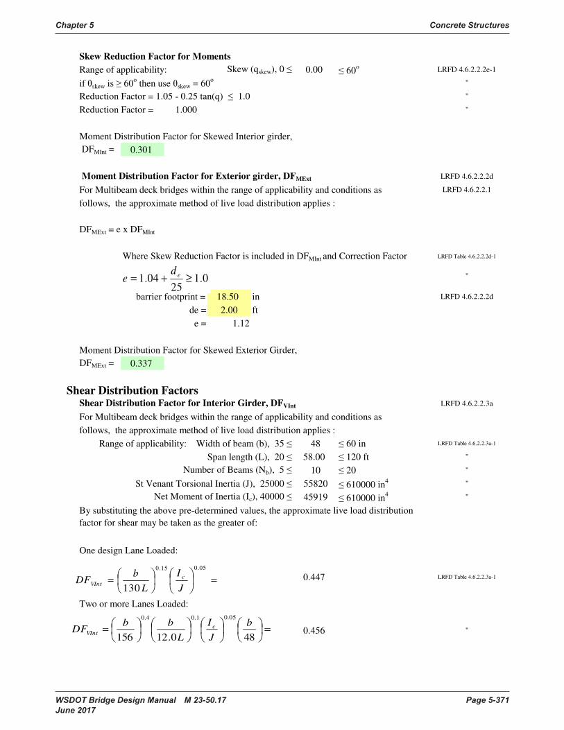
Chapter 5 Concrete Structures
WSDOT Bridge Design Manual M 23-50.17 Page 5-371 June 2017
Skew Reduction Factor for Moments
Range of applicability: Skew (qskew), 0 0.00 60o LRFD 4.6.2.2.2e-1
if skew is 60o then use skew = 60
o"
Reduction Factor = 1.05 - 0.25 tan(q) 1.0 "
Reduction Factor = 1.000 "
Moment Distribution Factor for Skewed Interior girder,
DFMInt = 0.301
Moment Distribution Factor for Exterior girder, DFMExt LRFD 4.6.2.2.2d
For Multibeam deck bridges within the range of applicability and conditions as LRFD 4.6.2.2.1
follows, the approximate method of live load distribution applies :
DFMExt = e x DFMInt
Where Skew Reduction Factor is included in DFMInt and Correction Factor LRFD Table 4.6.2.2.2d-1
barrier footprint = 18.50 in LRFD 4.6.2.2.2d
de = 2.00 ft
e = 1.12
Moment Distribution Factor for Skewed Exterior Girder,
DFMExt = 0.337
Shear Distribution FactorsShear Distribution Factor for Interior Girder, DFVInt LRFD 4.6.2.2.3a
For Multibeam deck bridges within the range of applicability and conditions as
follows, the approximate method of live load distribution applies :
Range of applicability: Width of beam (b), 35 48 60 in LRFD Table 4.6.2.2.3a-1
Span length (L), 20 58.00 120 ft "
Number of Beams (Nb), 5 10 20 "
St Venant Torsional Inertia (J), 25000 55820 610000 in4 "
Net Moment of Inertia (Ic), 40000 45919 610000 in4 "
One design Lane Loaded:
0.447 LRFD Table 4.6.2.2.3a-1
Two or more Lanes Loaded:
0.456 "
"
By substituting the above pre-determined values, the approximate live load distribution
factor for shear may be taken as the greater of:
0.125
04.1 ≥+=ed
e
=
=
05.015.0
130 J
I
L
bDF c
VInt
=
=480.12156
05.01.04.0b
J
I
L
bbDF c
VInt
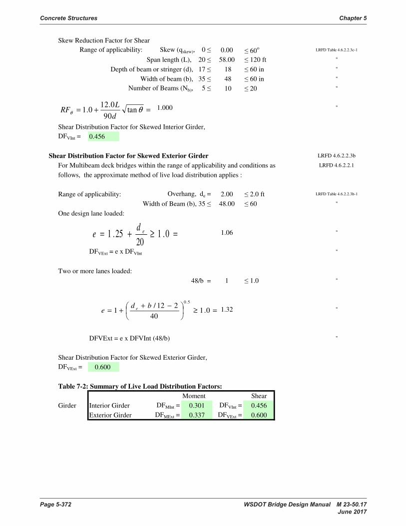
Concrete Structures Chapter 5
Page 5-372 WSDOT Bridge Design Manual M 23-50.17 June 2017
Skew Reduction Factor for Shear
Range of applicability: Skew (qskew), 0 0.00 60o LRFD Table 4.6.2.2.3c-1
Span length (L), 20 58.00 120 ft "
Depth of beam or stringer (d), 17 18 60 in "
Width of beam (b), 35 48 60 in "
Number of Beams (Nb), 5 10 20 "
1.000 "
Shear Distribution Factor for Skewed Interior Girder,
DFVInt = 0.456
Shear Distribution Factor for Skewed Exterior Girder LRFD 4.6.2.2.3b
For Multibeam deck bridges within the range of applicability and conditions as LRFD 4.6.2.2.1
follows, the approximate method of live load distribution applies :
Range of applicability: Overhang, de = 2.00 2.0 ft LRFD Table 4.6.2.2.3b-1
Width of Beam (b), 35 48.00 60 "
One design lane loaded:
1.06 "
DFVExt = e x DFVInt "
Two or more lanes loaded:
48/b = 1 1.0 "
1.32 "
DFVExt = e x DFVInt (48/b) "
Shear Distribution Factor for Skewed Exterior Girder,
DFVExt = 0.600
Table 7-2: Summary of Live Load Distribution Factors:
Moment Shear
Girder Interior Girder DFMInt = 0.301 DFVInt = 0.456
Exterior Girder DFMExt = 0.337 DFVExt = 0.600
=≥+= 0.120
25.1 ede
=+= θθ
tan90
0.120.1
d
LRF
=≥
−+
+= 0.140
212/1
5.0bd
e e
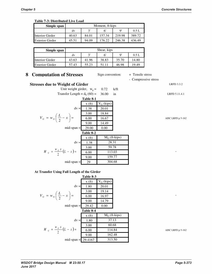
Chapter 5 Concrete Structures
WSDOT Bridge Design Manual M 23-50.17 Page 5-373 June 2017
Table 7-3: Distributed Live Load
Simple span
dv 3' 6' 9' 0.5 L
Interior Girder 40.63 84.01 157.34 219.98 389.72
Exterior Girder 45.51 94.09 176.22 246.38 436.49
Simple span
dv 3' 6' 9' 0.5 L
Interior Girder 43.63 41.96 38.83 35.70 14.80
Exterior Girder 57.43 55.23 51.11 46.98 19.49
8 Computation of Stresses Sign convention: + Tensile stress
- Compressive stress
Stresses due to Weight of Girder LRFD 3.3.2
Unit weight girder, wg = 0.72 k/ft
Transfer Length = db (60) = 36.00 in LRFD 5.11.4.1
Table 8-1
x (ft) VG (kips)
dv = 1.38 20.01
3.00 18.84
6.00 16.67 AISC LRFD p 5-162
9.00 14.49
mid-span = 29.00 0.00
Table 8-2
x (ft)
dv = 1.38
3.00
6.00 "
9.00
mid-span = 29
At Transfer Using Full Length of the Girder
Table 8-3
x (ft) VG (kips)
dv = 1.80 20.01
3.00 19.14
6.00 16.97 "
9.00 14.79
mid-span = 29.42 0.00
Table 8-4
x (ft)
dv = 1.80
3.00
6.00 AISC LRFD p 5-162
9.00
mid-span = 29.4167
MG (ft-kips)
59.78
60.68
113.03
Moment, ft-kips
Shear, kips
28.31
159.77
304.68
MG (ft-kips)
37.13
114.84
162.48
313.50
=
−= xL
wV GG2
( ) =−= xLxw
M G
G2
=
−= xL
wV GG2
( ) =−= xLxw
M G
G2
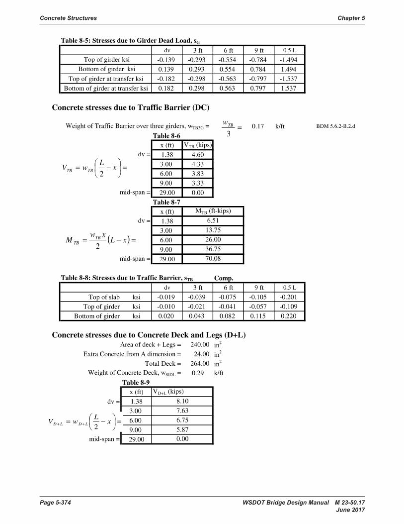
Concrete Structures Chapter 5
Page 5-374 WSDOT Bridge Design Manual M 23-50.17 June 2017
Table 8-5: Stresses due to Girder Dead Load, sG
dv 3 ft 6 ft 9 ft 0.5 L
-0.139 -0.293 -0.554 -0.784 -1.494
0.139 0.293 0.554 0.784 1.494
Top of girder at transfer ksi -0.182 -0.298 -0.563 -0.797 -1.537
Bottom of girder at transfer ksi 0.182 0.298 0.563 0.797 1.537
Concrete stresses due to Traffic Barrier (DC)
Weight of Traffic Barrier over three girders, wTB3G = 0.17 k/ft BDM 5.6.2-B.2.d
Table 8-6
x (ft) VTB (kips)
dv = 1.38 4.60
3.00 4.33
6.00 3.83
9.00 3.33
mid-span = 29.00 0.00
Table 8-7
x (ft)
dv = 1.38
3.00
6.00
9.00
mid-span = 29.00
Table 8-8: Stresses due to Traffic Barrier, sTB Comp.
dv 3 ft 6 ft 9 ft 0.5 L
Top of slab ksi -0.019 -0.039 -0.075 -0.105 -0.201
Top of girder ksi -0.010 -0.021 -0.041 -0.057 -0.109
Bottom of girder ksi 0.020 0.043 0.082 0.115 0.220
Area of deck + Legs = 240.00 in2
Extra Concrete from A dimension = 24.00 in2
Total Deck = 264.00 in2
Weight of Concrete Deck, wSIDL = 0.29 k/ft
Table 8-9
x (ft)
dv = 1.38
3.00
6.00
9.00
mid-span = 29.00
Concrete stresses due to Concrete Deck and Legs (D+L)
VD+L (kips)
13.75
8.10
6.51
7.63
MTB (ft-kips)
Bottom of girder ksi
6.75
5.87
0.00
26.00
36.75
70.08
Top of girder ksi
=
−= xL
wV TBTB2
( ) =−= xLxw
M TB
TB2
=3
TBw
=
−=++
xL
wV LDLD2
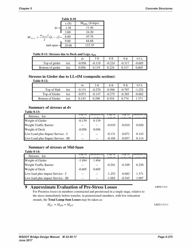
Chapter 5 Concrete Structures
WSDOT Bridge Design Manual M 23-50.17 Page 5-375 June 2017
Table 8-10
x (ft)
dv = 1.38
3.00
6.00
9.00
mid-span = 29.00
Table 8-11: Stresses due to Deck and Legs, sDW
dv 3 ft 6 ft 9 ft 0.5 L
Top of girder ksi -0.056 -0.119 -0.224 -0.317 -0.605
Bottom of girder ksi 0.056 0.119 0.224 0.317 0.605
Stresses in Girder due to LL+IM (composite section): Table 8-12:
dv 3 ft 6 ft 9 ft 0.5 L
Top of Slab ksi -0.131 -0.270 -0.506 -0.707 -1.252
Top of Girder ksi -0.071 -0.147 -0.275 -0.385 -0.682
Bottom of Girder ksi 0.143 0.296 0.554 0.774 1.371
Summary of stresses at dvTable 8-13:
Stresses, ksiTop of
girder
Bottom of
girder
Top of
slab ©
Top of
girder ©
Bottom of
girder ©Weight of Girder -0.139 0.139
Weight Traffic Barrier -- -- -0.019 -0.010 0.020
Weight of Deck -0.056 0.056
Live Load plus Impact Service - I -- -- -0.131 -0.071 0.143
Live Load plus Impact Service - III -- -- -0.104 -0.057 0.114
Summary of stresses at Mid-Span Table 8-14:
Stresses, ksiTop of
girder
Bottom of
girder
Top of
slab ©
Top of
girder ©
Bottom of
girder ©Weight of Girder -1.494 1.494
Weight Traffic Barrier -- -- -0.201 -0.109 0.220
Weight of Deck -0.605 0.605
Live load plus impact Service - I -- -- -1.252 -0.682 1.371
Live load plus impact Service - III -- -- -1.002 -0.545 1.097
9 Approximate Evaluation of Pre-Stress Losses LRFD 5.9.5
fpT = fpES + fpLT LRFD 5.9.5.1
For Prestress losses in members constructed and prestressed in a single stage, relative to
the stress immediately before transfer, in pretensioned members, with low relaxation
strands, the Total Lump Sum Losses may be taken as:
11.46
MSIDL (ft-kips)
123.35
24.20
45.76
64.68
( ) =−=+
+xL
xwM LD
LD2

Concrete Structures Chapter 5
Page 5-376 WSDOT Bridge Design Manual M 23-50.17 June 2017
Time Dependent Losses LRFD 5.9.5.3
19.53 ksi LRFD 5.9.5.3-1
h = 1.7-.01H =0.9 LRFD 5.9.5.3-2
st = 5/(1+fci)= 0.625 LRFD 5.9.5.3-3
determine the total losses.
Loss due to strand relaxationfpR = 2.50 LRFD 5.9.5.3
Loss due to elastic shortening fcgp = LRFD 5.9.5.2.3a
Concrete stress at Centroid of prestressing
Pi = N Aps .7fpu = 1148.4 kips BDM 5.1.4-A
-2.86 ksi
0.78 ksi
fcgp = fg + fps = -2.08 ksi BDM 5.1.4-3
Elastic shortening loss,
11.14 ksi LRFD 5.9.5.2.3a-1
fpT = fpES + fpLT = 30.67 ksi LRFD 5.9.5.1-1
Losses due to elastic shortening should be added to time-dependent losses to
Above relaxation losses not added to Time Dependent Losses, but will be used for
Service Limit State Total Transfer PS Losses, Section 10.
For normal weight concrete pretensioned by low-relaxation strands, approximate lump-
sum time dependent losses resulting from creep and shrinkage of concrete and relaxation
of prestressing steel may be used as follows:
Stress due to prestressing and girder weight at Centroid of prestressing
strands, at section of maximum moment
=−−=
g
i
g
i
psI
eP
A
Pf
2
==
g
g
gI
eMf
=
=∆ cgp
ci
p
pES fE
Ef
=∆++=∆ pRf1210 sthsth
g
pspi
pLTA
AFf γγγγ

Chapter 5 Concrete Structures
WSDOT Bridge Design Manual M 23-50.17 Page 5-377 June 2017
10 Stresses at Service Limit StateStresses after elastic shortening and relaxation :
Force per strand P / N = Aps(fpbt-DfpES-fpR) = 40.98 kips
Table 10-1:
No. of Force per Total Eccent. Moment
strands Strand, kips force in. in-kip
Bottom Strands 20 40.98 819.66 6.40 5246
Debonded Strands @ 3' 0 40.98 0.00 7.00 0
Debonded Strands @ 6' 2 40.98 81.97 7.00 574
Debonded Strands @ 9' 2 40.98 81.97 7.00 574
Top Strands 4 40.98 163.93 -6.00 -984
dv P ( kips )= 984 Mp(in-k) = 4262
3 P ( kips )= 984 Mp(in-k) = 4262
6 P ( kips )= 984 Mp(in-k) = 4262
9 P ( kips )= 1066 Mp(in-k) = 4836
mid P ( kips )= 1148 Mp(in-k) = 5410
dv mid-span
1.40 3.00 6.00 9.00 29.00
ksi 0.28 0.28 0.28 0.39 0.51
ksi -3.20 -3.20 -3.20 -3.56 -3.916
Force per strand P / N = Aps(fpbt-DfpT) = 37.29 kips BDM 5.1.4-A.1
Table 10-2:
No. of Force per Total Eccent. Moment
strands Strand, kips force in. in-kip
Bottom Strands 20 37.29 745.74 6.40 4773
Debonded Strands @ 3' 0 37.29 0.00 7.00 0
Debonded Strands @ 6' 2 37.29 74.57 7.00 522
Debonded Strands @ 9' 2 37.29 74.57 7.00 522
Top Strands 4 37.29 149.15 -6.00 -895
dv P ( kips )= 895 Mp(in-k) = 3878
3 P ( kips )= 894.89 Mp(in-k) = 3878
6 P ( kips )= 895 Mp(in-k) = 3878
9 P ( kips )= 969 Mp(in-k) = 4400
mid P ( kips )= 1044 Mp(in-k) = 4922
dv 3.00 6.00 9 mid-span
ksi 0.26 0.26 0.26 0.36 0.46
ksi -2.91 -2.91 -2.91 -3.24 -3.563
Prestressing stress (using the full length of the girder)
Stresses after Losses (noncomposite section)
Prestressing stress after all losses (noncomposite)
=+−=
t
ps
c
toppS
M
A
Pf )(
=−−=
b
ps
c
bottompS
M
A
Pf )(
=+−=
t
ps
c
toppS
M
A
Pf )(
=−−=
b
ps
c
bottompS
M
A
Pf )(
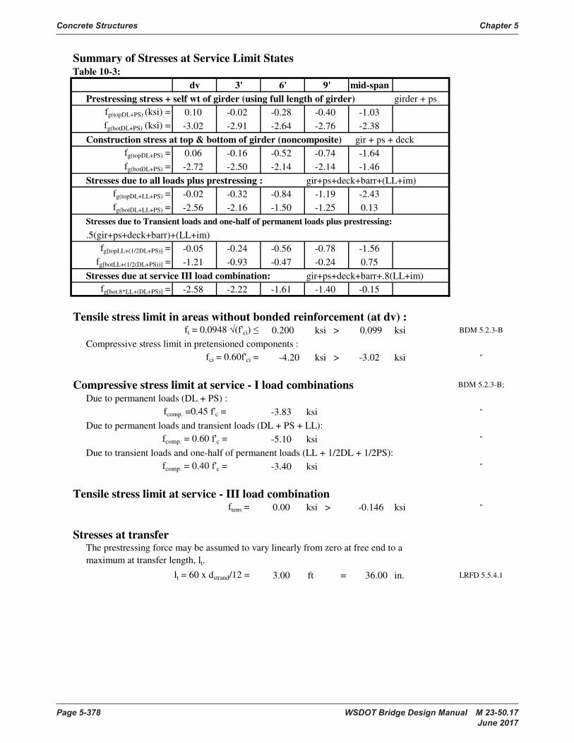
Concrete Structures Chapter 5
Page 5-378 WSDOT Bridge Design Manual M 23-50.17 June 2017
Summary of Stresses at Service Limit StatesTable 10-3:
dv 3' 6' 9' mid-span
Prestressing stress + self wt of girder (using full length of girder) girder + ps
fg(topDL+PS) (ksi) = 0.10 -0.02 -0.28 -0.40 -1.03
fg(botDL+PS) (ksi) = -3.02 -2.91 -2.64 -2.76 -2.38
Construction stress at top & bottom of girder (noncomposite) gir + ps + deck
fg(topDL+PS) = 0.06 -0.16 -0.52 -0.74 -1.64
fg(botDL+PS) = -2.72 -2.50 -2.14 -2.14 -1.46
Stresses due to all loads plus prestressing : gir+ps+deck+barr+(LL+im)
fg(topDL+LL+PS) = -0.02 -0.32 -0.84 -1.19 -2.43
fg(botDL+LL+PS) = -2.56 -2.16 -1.50 -1.25 0.13
Stresses due to Transient loads and one-half of permanent loads plus prestressing:
.5(gir+ps+deck+barr)+(LL+im)
fg[topLL+(1/2DL+PS)] = -0.05 -0.24 -0.56 -0.78 -1.56
fg[botLL+(1/2(DL+PS))] = -1.21 -0.93 -0.47 -0.24 0.75
Stresses due at service III load combination: gir+ps+deck+barr+.8(LL+im)
fg[bot.8*LL+(DL+PS)] = -2.58 -2.22 -1.61 -1.40 -0.15
Tensile stress limit in areas without bonded reinforcement (at dv) :ft = 0.0948 (f'ci) 0.200 ksi > 0.099 ksi BDM 5.2.3-B
Compressive stress limit in pretensioned components :
fci = 0.60f'ci = -4.20 ksi > -3.02 ksi "
Compressive stress limit at service - I load combinations BDM 5.2.3-B;
Due to permanent loads (DL + PS) :
fcomp. =0.45 f'c = -3.83 ksi "
Due to permanent loads and transient loads (DL + PS + LL):
fcomp. = 0.60 f'c = -5.10 ksi "
Due to transient loads and one-half of permanent loads (LL + 1/2DL + 1/2PS):
fcomp. = 0.40 f'c = -3.40 ksi "
Tensile stress limit at service - III load combinationftens = 0.00 ksi > -0.146 ksi "
Stresses at transfer
lt = 60 x dstrand/12 = 3.00 ft = 36.00 in. LRFD 5.5.4.1
The prestressing force may be assumed to vary linearly from zero at free end to a
maximum at transfer length, lt.
bc SA
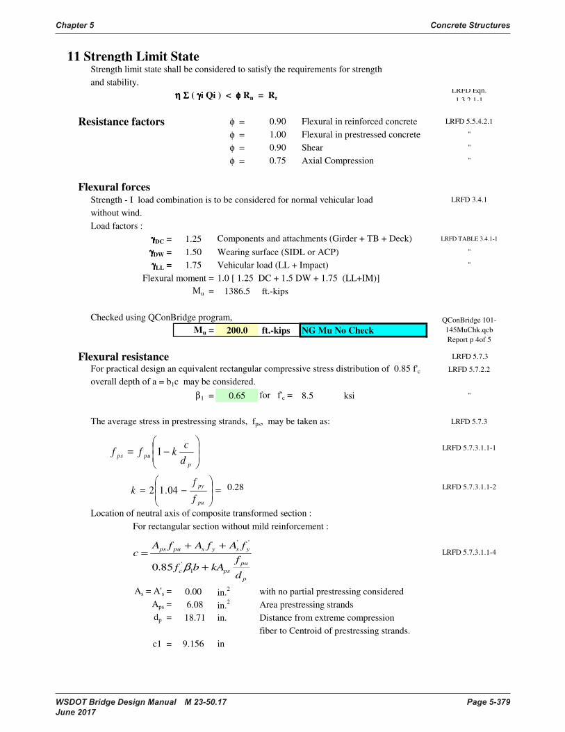
Chapter 5 Concrete Structures
WSDOT Bridge Design Manual M 23-50.17 Page 5-379 June 2017
11 Strength Limit StateStrength limit state shall be considered to satisfy the requirements for strength
and stability.
η Ση Ση Ση Σ ( γγγγi Qi ) < φφφφ Rn = Rr
LRFD Eqn.
1.3.2.1-1
Resistance factors φ = 0.90 Flexural in reinforced concrete LRFD 5.5.4.2.1
φ = 1.00 Flexural in prestressed concrete "
φ = 0.90 Shear "
φ = 0.75 Axial Compression "
Flexural forcesStrength - I load combination is to be considered for normal vehicular load LRFD 3.4.1
without wind.
Load factors :
γγγγDC = 1.25 LRFD TABLE 3.4.1-1
γγγγDW = 1.50 Wearing surface (SIDL or ACP) "
γγγγLL = 1.75 Vehicular load (LL + Impact) "
Flexural moment = 1.0 [ 1.25 DC + 1.5 DW + 1.75 (LL+IM)]
Mu = 1386.5 ft.-kips
Checked using QConBridge program,
Mu = 200.0 ft.-kips NG Mu No Check
Flexural resistance LRFD 5.7.3
LRFD 5.7.2.2
β1 = 0.65 for f'c = 8.5 ksi "
The average stress in prestressing strands, fps, may be taken as: LRFD 5.7.3
LRFD 5.7.3.1.1-1
0.28 LRFD 5.7.3.1.1-2
Location of neutral axis of composite transformed section :
For rectangular section without mild reinforcement :
LRFD 5.7.3.1.1-4
As = A's = 0.00 in.2 with no partial prestressing considered
Aps = 6.08 in.2 Area prestressing strands
dp = 18.71 in. Distance from extreme compression
fiber to Centroid of prestressing strands.
c1 = 9.156 in
QConBridge 101-
145MuChk.qcb
Report p 4of 5
Components and attachments (Girder + TB + Deck)
For practical design an equivalent rectangular compressive stress distribution of 0.85 f'c
overall depth of a = b1c may be considered.
−=
p
pupsd
ckff 1
=
−=
pu
py
f
fk 04.12
p
pu
psc
ysyspups
d
fkAbf
fAfAfAc
+
++=
1
'
''
85.0 β
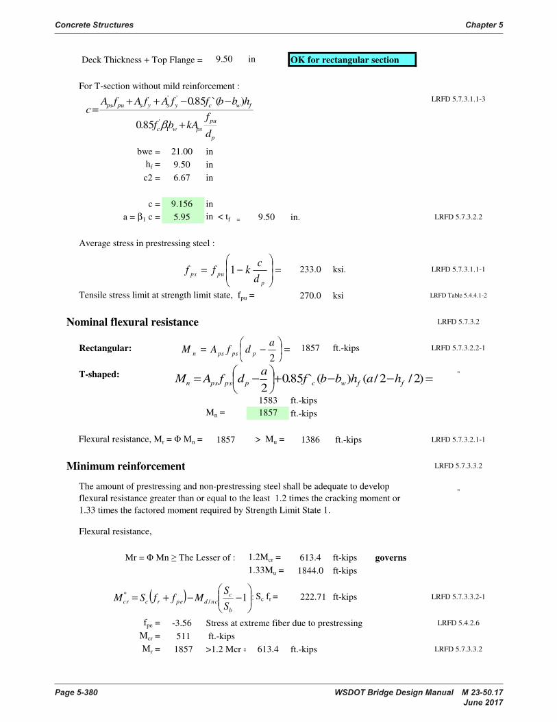
Concrete Structures Chapter 5
Page 5-380 WSDOT Bridge Design Manual M 23-50.17 June 2017
Deck Thickness + Top Flange = 9.50 in OK for rectangular section
For T-section without mild reinforcement :
LRFD 5.7.3.1.1-3
bwe = 21.00 in
hf = 9.50 in
c2 = 6.67 in
c = 9.156 in
a = β1 c = 5.95 in < tf = 9.50 in. LRFD 5.7.3.2.2
Average stress in prestressing steel :
233.0 ksi. LRFD 5.7.3.1.1-1
Tensile stress limit at strength limit state, fpu = 270.0 ksi LRFD Table 5.4.4.1-2
Nominal flexural resistance LRFD 5.7.3.2
Rectangular: 1857 ft.-kips LRFD 5.7.3.2.2-1
T-shaped: "
1583 ft.-kips
Mn = 1857 ft.-kips
Flexural resistance, Mr = Mn = 1857 > Mu = 1386 ft.-kips LRFD 5.7.3.2.1-1
Minimum reinforcement LRFD 5.7.3.3.2
"
Flexural resistance,
Mr = Mn The Lesser of : 1.2Mcr = 613.4 ft-kips governs
1.33Mu = 1844.0 ft-kips
Sc fr = 222.71 ft-kips LRFD 5.7.3.3.2-1
fpe = -3.56 Stress at extreme fiber due to prestressing LRFD 5.4.2.6
Mcr = 511 ft.-kips
Mr = 1857 >1.2 Mcr = 613.4 ft.-kips LRFD 5.7.3.3.2
The amount of prestressing and non-prestressing steel shall be adequate to develop
flexural resistance greater than or equal to the least 1.2 times the cracking moment or
1.33 times the factored moment required by Strength Limit State 1.
=
−=
p
pupsd
ckff 1
=
−=2
adfAM ppspsn
( )
−−+= 1/
*
b
c
ncdperccrS
SMffSM
p
pu
pswc
fwcysyspups
d
fkAbf
hbbffAfAfAc
+
−−++=
1
'
''
85.0
)`(85.0
β
=−−+
−= )2/2/()(`85.02
ffwcppspsn hahbbfa
dfAM
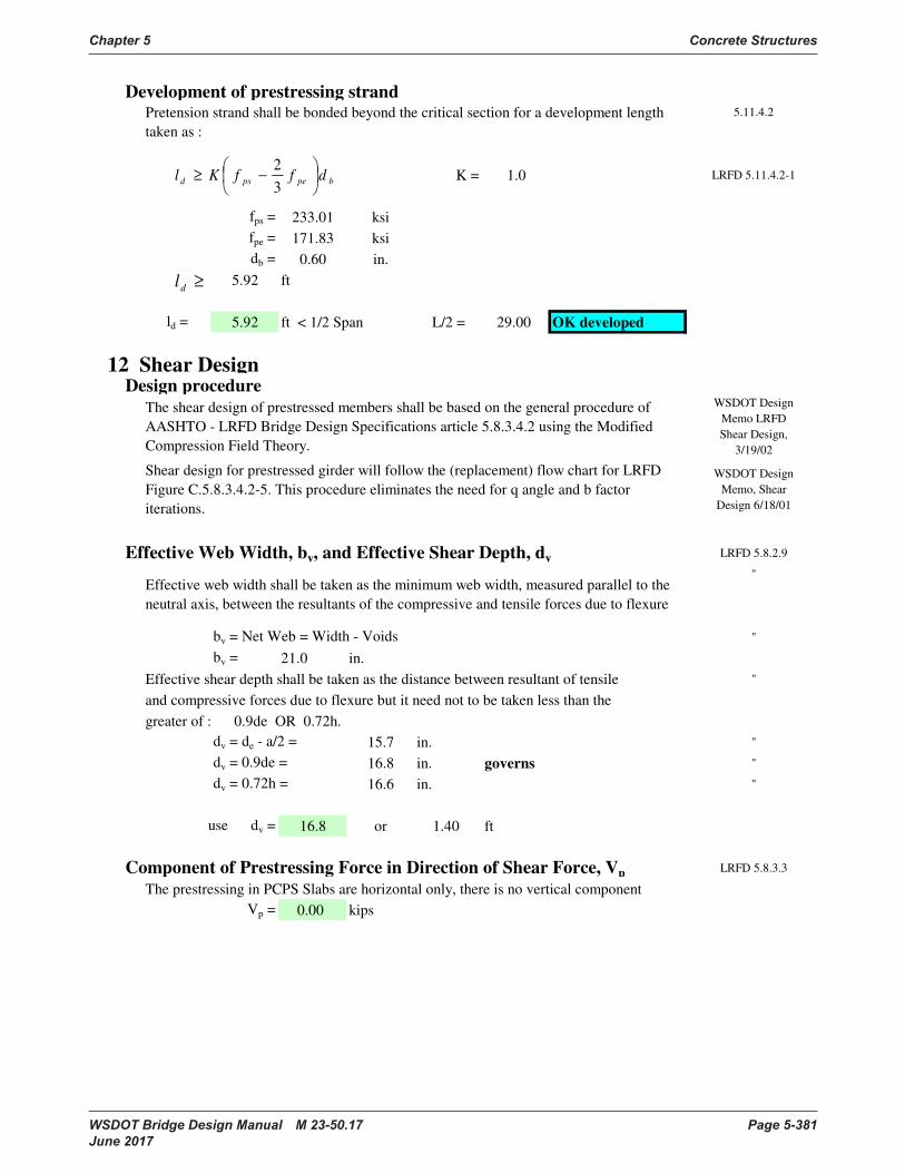
Chapter 5 Concrete Structures
WSDOT Bridge Design Manual M 23-50.17 Page 5-381 June 2017
Development of prestressing strand5.11.4.2
K = 1.0 LRFD 5.11.4.2-1
fps = 233.01 ksi
fpe = 171.83 ksi
db = 0.60 in.
5.92 ft
ld = 5.92 ft < 1/2 Span L/2 = 29.00 OK developed
12 Shear DesignDesign procedure
Effective Web Width, bv, and Effective Shear Depth, dv LRFD 5.8.2.9
"
bv = Net Web = Width - Voids "
bv = 21.0 in.
Effective shear depth shall be taken as the distance between resultant of tensile "
and compressive forces due to flexure but it need not to be taken less than the
greater of : 0.9de OR 0.72h.
dv = de - a/2 = 15.7 in. "
dv = 0.9de = 16.8 in. governs "
dv = 0.72h = 16.6 in. "
use dv = 16.8 or 1.40 ft
Component of Prestressing Force in Direction of Shear Force, Vp LRFD 5.8.3.3
The prestressing in PCPS Slabs are horizontal only, there is no vertical component
Vp = 0.00 kips
The shear design of prestressed members shall be based on the general procedure of
AASHTO - LRFD Bridge Design Specifications article 5.8.3.4.2 using the Modified
Compression Field Theory.
Shear design for prestressed girder will follow the (replacement) flow chart for LRFD
Figure C.5.8.3.4.2-5. This procedure eliminates the need for q angle and b factor
iterations.
Pretension strand shall be bonded beyond the critical section for a development length
taken as :
WSDOT Design
Memo, Shear
Design 6/18/01
Effective web width shall be taken as the minimum web width, measured parallel to the
neutral axis, between the resultants of the compressive and tensile forces due to flexure
WSDOT Design
Memo LRFD
Shear Design,
3/19/02
bpepsd dffKl
−≥3
2
≥dl
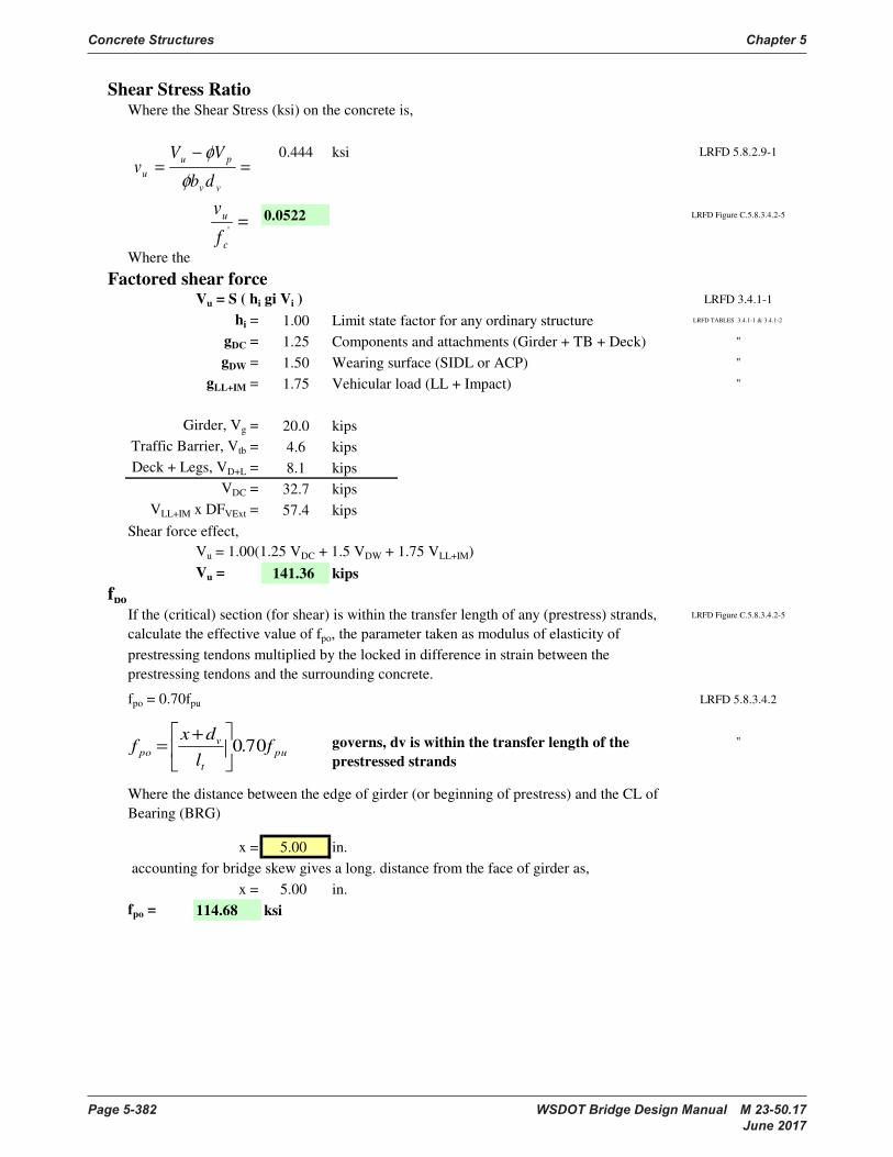
Concrete Structures Chapter 5
Page 5-382 WSDOT Bridge Design Manual M 23-50.17 June 2017
Shear Stress RatioWhere the Shear Stress (ksi) on the concrete is,
0.444 ksi LRFD 5.8.2.9-1
0.0522 LRFD Figure C.5.8.3.4.2-5
Where the
Factored shear forceVu = S ( hi gi Vi ) LRFD 3.4.1-1
hi = 1.00 Limit state factor for any ordinary structure LRFD TABLES 3.4.1-1 & 3.4.1-2
gDC = 1.25 Components and attachments (Girder + TB + Deck) "
gDW = 1.50 Wearing surface (SIDL or ACP) "
gLL+IM = 1.75 Vehicular load (LL + Impact) "
Girder, Vg = 20.0 kips
Traffic Barrier, Vtb = 4.6 kips
Deck + Legs, VD+L = 8.1 kips
VDC = 32.7 kips
VLL+IM x DFVExt = 57.4 kips
Shear force effect,
Vu = 1.00(1.25 VDC + 1.5 VDW + 1.75 VLL+IM)
Vu = 141.36 kips
fpo
LRFD Figure C.5.8.3.4.2-5
fpo = 0.70fpu LRFD 5.8.3.4.2
"
x = 5.00 in.
accounting for bridge skew gives a long. distance from the face of girder as,
x = 5.00 in.
fpo = 114.68 ksi
If the (critical) section (for shear) is within the transfer length of any (prestress) strands,
calculate the effective value of fpo, the parameter taken as modulus of elasticity of
prestressing tendons multiplied by the locked in difference in strain between the
prestressing tendons and the surrounding concrete.
Where the distance between the edge of girder (or beginning of prestress) and the CL of
Bearing (BRG)
governs, dv is within the transfer length of the
prestressed strands
='
c
u
f
v
=−
=
vv
pu
udb
VVv
φ
φ
pu
t
v
po fl
dxf 70.0
+=

Chapter 5 Concrete Structures
WSDOT Bridge Design Manual M 23-50.17 Page 5-383 June 2017
Factored MomentWhere: Factored moment is not to be taken less than Vudv LRFD 5.8.3.4.2
Mu = Σ ( ηi γi Mi ) LRFD 1.3.2.1-1
Ultimate moment at dv from support, Mu
Girder, Mg = 28.8 ft-kips
Traffic Barrier, Mtb = 6.6 ft-kips
Deck + Legs, MD+L = 11.7 ft-kips
MDC = 47.0 ft-kips
MLL+IM x DFMExt = 45.5 ft-kips
Moment Force Effect,
Mu = 1.00(1.25MDC + 1.50MDW + 1.75MLL+IM) LRFD TABLE 3.4.1-1
Mu = 138.5 ft-kips = 1661.5 in - kips
Check which value governs:
Vudv = 2381.0 in - kips governs
Mu = 1661.5 in - kips
Applied Factored Axial forces,
Nu = 0.00 kips
Factored Shear,
Vu = 141.36 kips
Vertical Component of Prestress Forces,
Vp = 0.00
Area of prestressing steel on the flexural tension side of the member,
Aps(T) = Nbb x Aps = 4.34 in.2
Prestress/Concrete Modulus of Elasticity Parameter
fpo = 114.68 ksi
Modulus of Elasticity of Mild Reinforcement,
Es = 29000 ksi
Area of Mild Reinforcement in flexural tension side of the member,
As(bottom) = ns(bottom)As
Where there are 4 No. 4 bars BDM fig. 5-A-XX
As(bottom) = 0.80 in.2
Modulus of Elasticity of Prestress Strands,
Ep = 28500 ksi
Substitution gives,
εx = < 0, so use the following Equation 3: LRFD 5.8.3.4.2-1
Longitudinal Strain (Flexural Tension) WSDOT Design
Memo Shear
Design, 6/18/2001
& LRFD 5.8.3.4.2-
1
The section contains at least the minimum transverse reinforcement as specified in
Article 5.8.2.5. Longitudinal strain in the "web reinforcement" on the flexural tension
side of the member,
-0.0007317
002.0)(2
5.0
≤+
−−++
=
pspss
popspuu
v
u
xAEAE
fAVVNd
M
ε
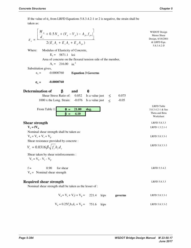
Concrete Structures Chapter 5
Page 5-384 WSDOT Bridge Design Manual M 23-50.17 June 2017
Where: Modulus of Elasticity of Concrete,
Ec = 5871.1 ksi
Area of concrete on the flexural tension side of the member,
Ac = 216.00 in.2
Substitution gives,
ex = Equation 3 Governs
ex =
Determination of β β β β and θ θ θ θ
Shear Stress Ratio of: 0.052 Is a value just 0.075
1000 x the Long. Strain: -0.076 Is a value just -0.05
From Table 1: θ = θ = θ = θ = 21.00 deg.
β = β = β = β = 4.10
Shear strength LRFD 5.8.3.3
Vr = fVn LRFD 1.3.2.1-1
Nominal shear strength shall be taken as:
Vn = Vc + Vs + Vp LRFD 5.8.3.3-1
Shear resistance provided by concrete :
LRFD 5.8.3.3-3
Shear taken by shear reinforcements :
Vs = Vn - Vc - Vp
f = 0.90 for shear LRFD 5.5.4.2
Vn = Nominal shear strength
Required shear strength LRFD 5.8.3.3
Nominal shear strength shall be taken as the lesser of :
Vn = Vc + Vsi + Vp = 221.4 kips governs LRFD 5.8.3.3-1
Vn = 0.25f'cbvdv + Vp = 751.6 kips LRFD 5.8.3.3-2
WSDOT Design
Memo Shear
Design, 6/18/2001
& LRFD Eqn.
5.8.3.4.2-3
If the value of ex from LRFD Equations 5.8.3.4.2-1 or 2 is negative, the strain shall be
taken as:
-0.0000760
LRFD Table
5.8.3.4.2-1 & See
Theta and Beta
Worksheet
-0.0000760
vvcc dbfV'0316.0 β=
)(2
)(5.0
pspsscc
popspuu
v
u
xAEAEAE
fAVVNd
M
++
−−++
=ε
≤
≤

Chapter 5 Concrete Structures
WSDOT Bridge Design Manual M 23-50.17 Page 5-385 June 2017
Initial Shear from stirrups, based on 12" spacing of #4 bars
87.75 kips LRFD C5.8.3.3-1
Shear resistance provided by concrete :
133.6 kips LRFD 5.8.3.3-3
Shear taken by shear reinforcement:
Vsreq = Vu/ø - Vc - Vp = 23.5 kips LRFD 5.8.3.3-1
Spacing of shear reinforcements :
Try 2 legs of # 4 Av = 0.40 in.2
Required Spacing, 44.87 in. LRFD C5.8.3.3-1
Maximum spacing of shear reinforcement if vu < 0.125 f'c then smax = 0.8 dv < 24 in. 18 in. LRFD 5.8.2.7-1
Maximum spacing of shear reinforcement, WSDOT Practice = 18.00 in
if vu >= 0.125 f'c then s < 0.4 dv < 12 in.
vu = 0.444 ksi LRFD 5.8.2.7-2
0.125 f'c = 1.063 ksi > vu = 0.444 ksi
Maximum spacing, smax = 13.5 in. Governs spacing
Governing spacing, sgov = 13.0 in.
Av(provided) = 0.40 in.2 Assuming two #4 legs
81.00 kips LRFD C5.8.3.3-1
Shear reinforcement is required if : 0.5f(Vc+Vp) < Vu LRFD 5.8.2.4-1
0.5f(Vc+Vp) = 60.1 < Vu = 141.4 kips
Yes, Shear/Transverse Reinf. Is Required
Minimum shear reinforcement LRFD 5.8.2.5
Use Spacing: 12.00 in 13.0 in LRFD 5.8.2.5-1
OK
where :
s = 12.0 in.
Required Area of Steel,
0.39 in.2
0.40 > 0.39 in.2 OK for Min. Transverse Reinf.
When shear reinforcement is required by design, the area of steel provided,
== vvcc dbfV'0316.0 β
==
s
vyv
dreqV
dfAs
θcot'
==
gov
vyv
ss
dfAV
θcot
y
govv
cprovidedvf
sbfA
'
)( 0316.0≥
=
y
govv
cf
sbf
'0316.0
==
gov
vyv
ss
dfAiV
θcot

Concrete Structures Chapter 5
Page 5-386 WSDOT Bridge Design Manual M 23-50.17 June 2017
Longitudinal reinforcement LRFD 5.8.3.5
LRFD 5.8.3.5-1
As = 0.80 in2 BDM fig. 5-A-XX
fy = 60.00 ksi
Aps = 4.34 in2
fps = 233.01 ksi
dv = 16.84 in.
lt = 3.00 ft = 36.00 in
Mu = 198.4 ft-kips
f = 1.00 Flexural in prestressed concrete LRFD 5.5.4.2
f = 0.90 Shear "
f = 0.75 Axial Compression "
Nu = 0.00
Vu = 141.36 kips
Vs = 81.00 kips
Vp = 0.00 kips
q = 21.00 degree
by substitution:
521.135 445.0 kips OK for Longitudinal Reinforcement
13 Deflection and Camber LRFD 5.7.3.6.2
Let downward Deflection be Positive +
Let upward Deflection, Camber, be Negative -
Deflection due to prestressing forces at Transfer
Pbb = 819.66 kips ebb = 6.40 in
Longitudinal reinforcement shall be provided so that at each section the following
equations are satisfied :
Deflection due to bottom strands is computed from a combination of fully bonded strands
and the partially bonded or "debonded" strands which are sleeved at the ends of the
girder. Each type has their own eccentricity.
Area of prestressing steel on the flexural tension side of
the member (w/o unbonded)
fps multiplied by dv/lt ratio to account for lack of
prestress development
Force and eccentricity due to the bonded bottom prestress strands are:
θφφφ
cot5.05.0
−−++=≥
+ ps
uu
v
u
t
v
pspsys VVVN
d
MT
l
dfAfA
≥
dbbbbot pspsps ∆+∆=∆ .
( )cci
dbdbdbbbbbdbbbIE
LePkePpsps
8
2
+=∆+∆
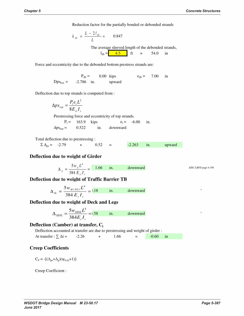
Chapter 5 Concrete Structures
WSDOT Bridge Design Manual M 23-50.17 Page 5-387 June 2017
Reduction factor for the partially bonded or debonded strands
0.847
The average sleeved length of the debonded strands,
ldb = 4.5 ft = 54.0 in
Pdb = 0.00 kips edb = 7.00 in
Dpsbot. = -2.786 in. upward
Deflection due to top strands is computed from :
Prestressing force and eccentricity of top strands.
Pt = 163.9 kips et = -6.00 in.
∆pstop = 0.522 in. downward
Total deflection due to prestressing :
Σ ∆ps = -2.79 + 0.52 = -2.263 in. upward
Deflection due to weight of Girder
1.66 in. downward AISC LRFD page 4-190
Deflection due to weight of Traffic Barrier TB
0.18 in. downward "
Deflection due to weight of Deck and Legs
0.58 in. downward "
Deflection (Camber) at transfer, Ci
Deflection accounted at transfer are due to prestressing and weight of girder :
At transfer : i = -2.26 + 1.66 = -0.60 in
Creep Coefficients
CF = -[(ps+g)((t,ti)+1)]
Creep Coefficient :
Force and eccentricity due to the debonded bottom prestress strands are:
==∆
cci
g
gIE
Lw
384
5 4
=−
=L
lLk db
db
2
cci
tt
topIE
LePps
8
2
=∆
==∆
cc
SIDL
SIDLIE
Lw
384
5 4
==∆
cc
Gtb
tbIE
Lw
384
54
)3(
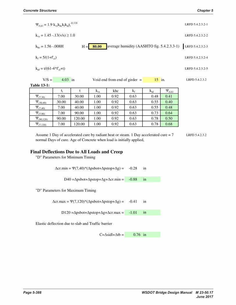
Concrete Structures Chapter 5
Page 5-388 WSDOT Bridge Design Manual M 23-50.17 June 2017
(t,ti) = 1.9 kvskhckfktati-0.118
LRFD 5.4.2.3.2-1
kvs = 1.45 -.13(v/s) 1.0 LRFD 5.4.2.3.2-2
khc = 1.56 -.008H H = 80.00 LRFD 5.4.2.3.2-3
kf = 5/(1+f'ci) LRFD 5.4.2.3.2-4
ktd = t/(61-4*f'ci+t) LRFD 5.4.2.3.2-5
V/S = 4.03 in Void end from end of girder = 15 in. LRFD 5.4.2.3.2
Table 13-1:
ti t kvs khc kf ktd (t,ti)
(7,30) 7.00 30.00 1.00 0.92 0.63 0.48 0.41
(30,40) 30.00 40.00 1.00 0.92 0.63 0.55 0.40
(7,40) 7.00 40.00 1.00 0.92 0.63 0.55 0.48
(7,90) 7.00 90.00 1.00 0.92 0.63 0.73 0.64
(90,120) 90.00 120.00 1.00 0.92 0.63 0.78 0.50
(7,120) 7.00 120.00 1.00 0.92 0.63 0.78 0.68
LRFD 5.4.2.3.2
Final Deflections Due to All Loads and Creep"D" Parameters for Minimum Timing
cr.min = (7,40)*(psbot+pstop+g) = -0.28 in
D40 =psbot+pstop+g+cr.min = -0.88 in
"D" Parameters for Maximum Timing
cr.max = (7,120)*(psbot+pstop+g) = -0.41 in
D120 =psbot+pstop+g+cr.max = -1.01 in
Elastic deflection due to slab and Traffic barrier
C=sidl+tb = 0.76 in
Assume 1 Day of accelerated cure by radiant heat or steam. 1 Day accelerated cure = 7
normal Days of cure. Age of Concrete when load is initially applied,
average humidity (AASHTO fig. 5.4.2.3.3-1)
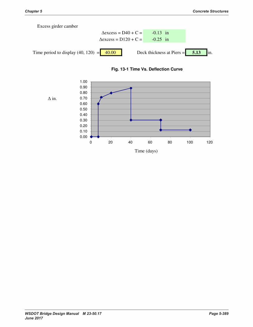
Chapter 5 Concrete Structures
WSDOT Bridge Design Manual M 23-50.17 Page 5-389 June 2017
Excess girder camber
excess = D40 + C = -0.13 in
excess = D120 + C = -0.25 in
Time period to display (40, 120) = 40.00 Deck thickness at Piers = 5.13 in.
in.
Time (days)
Fig. 13-1 Time Vs. Deflection Curve
0.00
0.10
0.20
0.30
0.40
0.50
0.60
0.70
0.80
0.90
1.00
0 20 40 60 80 100 120
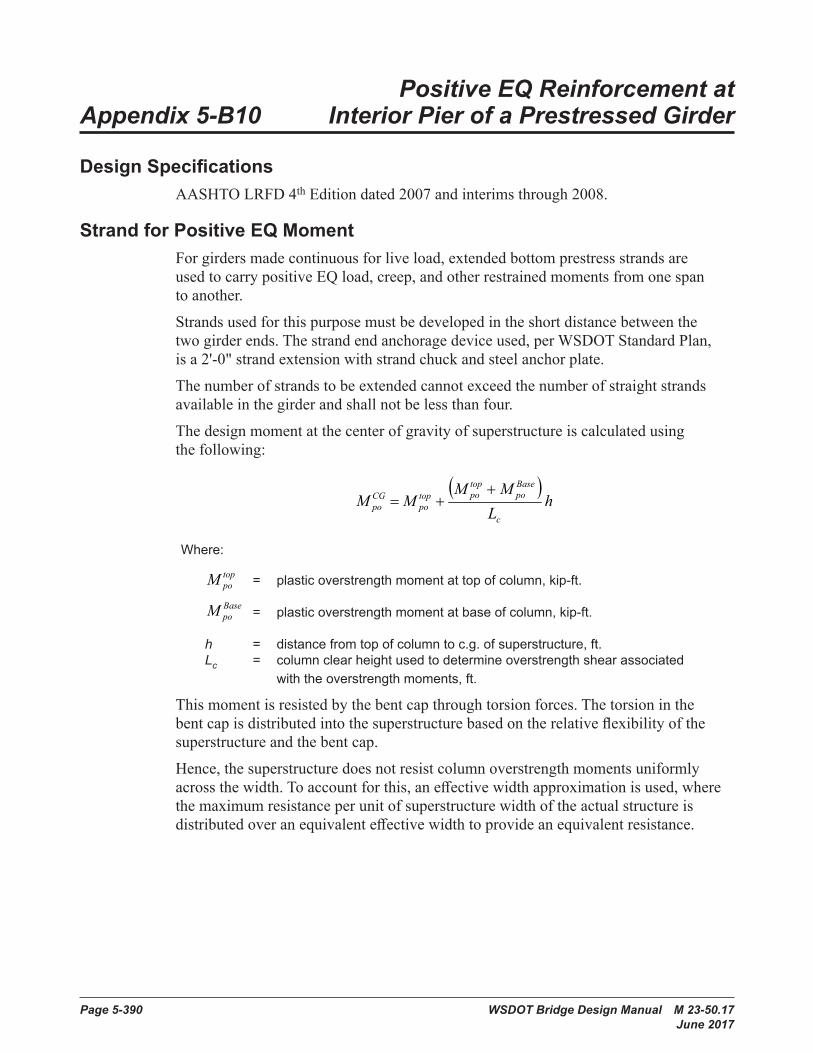
Page 5-390 WSDOT Bridge Design Manual M 23-50.17 June 2017
Positive EQ Reinforcement at Appendix 5-B10 Interior Pier of a Prestressed Girder
Design SpecificationsAASHTO LRFD 4th Edition dated 2007 and interims through 2008.
Strand for Positive EQ MomentForgirdersmadecontinuousforliveload,extendedbottomprestressstrandsareused to carry positive EQ load, creep, and other restrained moments from one span to another.
Strandsusedforthispurposemustbedevelopedintheshortdistancebetweenthetwo girder ends. The strand end anchorage device used, per WSDOT Standard Plan, isa2'-0"strandextensionwithstrandchuckandsteelanchorplate.
Thenumberofstrandstobeextendedcannotexceedthenumberofstraightstrandsavailableinthegirderandshallnotbelessthanfour.
The design moment at the center of gravity of superstructure is calculated using thefollowing:
Design Specifications:
Strand for Positive EQ Moment:
For girders made continuous for live load, extendedbottomprestressstrandsareusedtocarrypositive EQ load, creep, and other restrained moments from one span to another.
Strandsusedforthispurposemustbedevelopedintheshortdistancebetweenthetwogirderends.The strand end anchorage device used, per WSDOT StandardPlan,isa2'-0"strandextensionwithstrand chuck and steel anchor plate.
Thenumberofstrandstobeextendedcannotexceedthenumberofstraightstrandsavailableinthegirderandshallnotbelessthanfour.
The design moment at the center of gravity of superstructureiscalculatedusingthefollowing:
where:
= plastic overstrength moment at top of column, kip-ft.
= plasticoverstrengthmomentatbaseofcolumn,kip-ft.
= distance from top of column to c.g. of superstructure, ft.
= column clear height used to determine overstrength shear associated with the overstrength moments, ft.
Thismomentisresistedbythebentcapthroughtorsionforces.Thetorsioninthebentcapisdistributedintothesuperstructurebasedontherelativeflexibilityofthesuperstructureandthebentcap.
Hence, the superstructure does not resist column overstrength moments uniformly across the width. To account for this, an effective width approximation is used, where the maximum resistance per unit of superstructure width of the actual structure is distributedoveranequivalenteffectivewidthtoprovide an equivalent resistance.
Ithasbeensuggestedthatforconcretebridges,withtheexceptionofboxgirdersandsolidsuperstructure,thiseffectivewidthshouldbecalculatedasfollows:
where:
= diameter of column
= depthofsuperstructureincludingcapbeam
Based on the structural testing conducted at the University of California at San Diego La Jolla, Californiainthelate1990's(Holombo2000),roughlytwo-thirdsofthecolumnplasticmomenttoberesistedbythetwogirdersadjacenttothecolumn(encompassedbytheeffectivewidth)andtheotherone-thirdtoberesistedbythenon-adjacentgirders.
( )h
LMM
MMc
Basepo
toppotop
poCGpo
++=
BasepoM
h
cL
sceff DDB +=
cD
sD
toppoM
Where:
Design Specifications:
Strand for Positive EQ Moment:
For girders made continuous for live load, extendedbottomprestressstrandsareusedtocarrypositive EQ load, creep, and other restrained moments from one span to another.
Strandsusedforthispurposemustbedevelopedintheshortdistancebetweenthetwogirderends.The strand end anchorage device used, per WSDOT StandardPlan,isa2'-0"strandextensionwithstrand chuck and steel anchor plate.
Thenumberofstrandstobeextendedcannotexceedthenumberofstraightstrandsavailableinthegirderandshallnotbelessthanfour.
The design moment at the center of gravity of superstructureiscalculatedusingthefollowing:
where:
= plastic overstrength moment at top of column, kip-ft.
= plasticoverstrengthmomentatbaseofcolumn,kip-ft.
= distance from top of column to c.g. of superstructure, ft.
= column clear height used to determine overstrength shear associated with the overstrength moments, ft.
Thismomentisresistedbythebentcapthroughtorsionforces.Thetorsioninthebentcapisdistributedintothesuperstructurebasedontherelativeflexibilityofthesuperstructureandthebentcap.
Hence, the superstructure does not resist column overstrength moments uniformly across the width. To account for this, an effective width approximation is used, where the maximum resistance per unit of superstructure width of the actual structure is distributedoveranequivalenteffectivewidthtoprovide an equivalent resistance.
Ithasbeensuggestedthatforconcretebridges,withtheexceptionofboxgirdersandsolidsuperstructure,thiseffectivewidthshouldbecalculatedasfollows:
where:
= diameter of column
= depthofsuperstructureincludingcapbeam
Based on the structural testing conducted at the University of California at San Diego La Jolla, Californiainthelate1990's(Holombo2000),roughlytwo-thirdsofthecolumnplasticmomenttoberesistedbythetwogirdersadjacenttothecolumn(encompassedbytheeffectivewidth)andtheotherone-thirdtoberesistedbythenon-adjacentgirders.
( )h
LMM
MMc
Basepo
toppotop
poCGpo
++=
BasepoM
h
cL
sceff DDB +=
cD
sD
toppoM
= plastic overstrength moment at top of column, kip-ft .
Design Specifications:
Strand for Positive EQ Moment:
For girders made continuous for live load, extendedbottomprestressstrandsareusedtocarrypositive EQ load, creep, and other restrained moments from one span to another.
Strandsusedforthispurposemustbedevelopedintheshortdistancebetweenthetwogirderends.The strand end anchorage device used, per WSDOT StandardPlan,isa2'-0"strandextensionwithstrand chuck and steel anchor plate.
Thenumberofstrandstobeextendedcannotexceedthenumberofstraightstrandsavailableinthegirderandshallnotbelessthanfour.
The design moment at the center of gravity of superstructureiscalculatedusingthefollowing:
where:
= plastic overstrength moment at top of column, kip-ft.
= plasticoverstrengthmomentatbaseofcolumn,kip-ft.
= distance from top of column to c.g. of superstructure, ft.
= column clear height used to determine overstrength shear associated with the overstrength moments, ft.
Thismomentisresistedbythebentcapthroughtorsionforces.Thetorsioninthebentcapisdistributedintothesuperstructurebasedontherelativeflexibilityofthesuperstructureandthebentcap.
Hence, the superstructure does not resist column overstrength moments uniformly across the width. To account for this, an effective width approximation is used, where the maximum resistance per unit of superstructure width of the actual structure is distributedoveranequivalenteffectivewidthtoprovide an equivalent resistance.
Ithasbeensuggestedthatforconcretebridges,withtheexceptionofboxgirdersandsolidsuperstructure,thiseffectivewidthshouldbecalculatedasfollows:
where:
= diameter of column
= depthofsuperstructureincludingcapbeam
Based on the structural testing conducted at the University of California at San Diego La Jolla, Californiainthelate1990's(Holombo2000),roughlytwo-thirdsofthecolumnplasticmomenttoberesistedbythetwogirdersadjacenttothecolumn(encompassedbytheeffectivewidth)andtheotherone-thirdtoberesistedbythenon-adjacentgirders.
( )h
LMM
MMc
Basepo
toppotop
poCGpo
++=
BasepoM
h
cL
sceff DDB +=
cD
sD
toppoM
= plastic overstrength moment at base of column, kip-ft. h = distance from top of column to c .g . of superstructure, ft . Lc = column clear height used to determine overstrength shear associated with the overstrength moments, ft .
Thismomentisresistedbythebentcapthroughtorsionforces.Thetorsioninthebentcapisdistributedintothesuperstructurebasedontherelativeflexibilityofthesuperstructureandthebentcap.
Hence, the superstructure does not resist column overstrength moments uniformly acrossthewidth.Toaccountforthis,aneffectivewidthapproximationisused,wherethe maximum resistance per unit of superstructure width of the actual structure is distributedoveranequivalenteffectivewidthtoprovideanequivalentresistance.
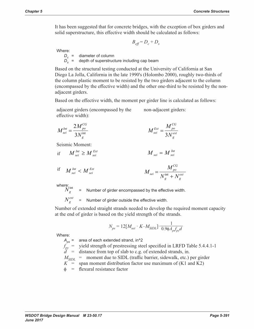
Chapter 5 Concrete Structures
WSDOT Bridge Design Manual M 23-50.17 Page 5-391 June 2017
Ithasbeensuggestedthatforconcretebridges,withtheexceptionofboxgirdersandsolidsuperstructure,thiseffectivewidthshouldbecalculatedasfollows:
Beff = Dc + Ds
Where: Dc = diameter of column Ds = depth of superstructure including cap beam
Based on the structural testing conducted at the University of California at San DiegoLaJolla,Californiainthelate1990's(Holombo2000),roughlytwo-thirdsofthecolumnplasticmomenttoberesistedbythetwogirdersadjacenttothecolumn(encompassedbytheeffectivewidth)andtheotherone-thirdtoberesistedbythenon-adjacent girders.
Basedontheeffectivewidth,themomentpergirderlineiscalculatedasfollows:
adjacentgirders(encompassedbytheeffectivewidth):
non-adjacentgirders:Basedontheeffectivewidth,themomentpergirderlineiscalculatedasfollows:
adjacentgirders(encompassedbytheeffectivewidth): non-adjacentgirders:
SeismicMoment:
if
if
where:
= Numberofgirderencompassedbytheeffectivewidth.
= Numberofgirderoutsidetheeffectivewidth.
Numberofextendedstraightstrandsneededtodevelop the required moment capacity at the end of girderisbasedontheyieldstrengthofthestrands.
where:
= area of each extended strand, in^2
= yieldstrengthofprestressingsteelspecifiedinLRFDTable5.4.4.1-1
= distancefromtopofslabtoc.g.ofextendedstrands,in.
= momentduetoSIDL(trafficbarrier,sidewalk,etc.)pergirder
= spanmomentdistributionfactor use maximum of (K1 and K2)
= flexural resistance factor
Assume EI is constant and Girders havefixed-fixedsupportsforbothspans.
int32
g
CGpoInt
sei NM
M = extg
CGpoExt
sei NM
M3
=
Extsei
Intsei MM ≥ Int
seisei MM =
Extsei
Intsei MM <
int extgg
CGpo
sei NNM
M+
=
intgN
extgN
[ ]dfA
MKMNpyps
SIDLseips φ9.0112 •• −=
psA
pyf
dSIDLM
K
φ
c.g. of Superstc.g. of ext. Str.
h
d
1K 2K
1L 2L 21
11 LL
LK+
=21
22 LL
LK+
=
Basedontheeffectivewidth,themomentpergirderlineiscalculatedasfollows:
adjacentgirders(encompassedbytheeffectivewidth): non-adjacentgirders:
SeismicMoment:
if
if
where:
= Numberofgirderencompassedbytheeffectivewidth.
= Numberofgirderoutsidetheeffectivewidth.
Numberofextendedstraightstrandsneededtodevelop the required moment capacity at the end of girderisbasedontheyieldstrengthofthestrands.
where:
= area of each extended strand, in^2
= yieldstrengthofprestressingsteelspecifiedinLRFDTable5.4.4.1-1
= distancefromtopofslabtoc.g.ofextendedstrands,in.
= momentduetoSIDL(trafficbarrier,sidewalk,etc.)pergirder
= spanmomentdistributionfactor use maximum of (K1 and K2)
= flexural resistance factor
Assume EI is constant and Girders havefixed-fixedsupportsforbothspans.
int32
g
CGpoInt
sei NM
M = extg
CGpoExt
sei NM
M3
=
Extsei
Intsei MM ≥ Int
seisei MM =
Extsei
Intsei MM <
int extgg
CGpo
sei NNM
M+
=
intgN
extgN
[ ]dfA
MKMNpyps
SIDLseips φ9.0112 •• −=
psA
pyf
dSIDLM
K
φ
c.g. of Superstc.g. of ext. Str.
h
d
1K 2K
1L 2L 21
11 LL
LK+
=21
22 LL
LK+
=
SeismicMoment:
Basedontheeffectivewidth,themomentpergirderlineiscalculatedasfollows:
adjacentgirders(encompassedbytheeffectivewidth): non-adjacentgirders:
SeismicMoment:
if
if
where:
= Numberofgirderencompassedbytheeffectivewidth.
= Numberofgirderoutsidetheeffectivewidth.
Numberofextendedstraightstrandsneededtodevelop the required moment capacity at the end of girderisbasedontheyieldstrengthofthestrands.
where:
= area of each extended strand, in^2
= yieldstrengthofprestressingsteelspecifiedinLRFDTable5.4.4.1-1
= distancefromtopofslabtoc.g.ofextendedstrands,in.
= momentduetoSIDL(trafficbarrier,sidewalk,etc.)pergirder
= spanmomentdistributionfactor use maximum of (K1 and K2)
= flexural resistance factor
Assume EI is constant and Girders havefixed-fixedsupportsforbothspans.
int32
g
CGpoInt
sei NM
M = extg
CGpoExt
sei NM
M3
=
Extsei
Intsei MM ≥ Int
seisei MM =
Extsei
Intsei MM <
int extgg
CGpo
sei NNM
M+
=
intgN
extgN
[ ]dfA
MKMNpyps
SIDLseips φ9.0112 •• −=
psA
pyf
dSIDLM
K
φ
c.g. of Superstc.g. of ext. Str.
h
d
1K 2K
1L 2L 21
11 LL
LK+
=21
22 LL
LK+
=
where:
Basedontheeffectivewidth,themomentpergirderlineiscalculatedasfollows:
adjacentgirders(encompassedbytheeffectivewidth): non-adjacentgirders:
SeismicMoment:
if
if
where:
= Numberofgirderencompassedbytheeffectivewidth.
= Numberofgirderoutsidetheeffectivewidth.
Numberofextendedstraightstrandsneededtodevelop the required moment capacity at the end of girderisbasedontheyieldstrengthofthestrands.
where:
= area of each extended strand, in^2
= yieldstrengthofprestressingsteelspecifiedinLRFDTable5.4.4.1-1
= distancefromtopofslabtoc.g.ofextendedstrands,in.
= momentduetoSIDL(trafficbarrier,sidewalk,etc.)pergirder
= spanmomentdistributionfactor use maximum of (K1 and K2)
= flexural resistance factor
Assume EI is constant and Girders havefixed-fixedsupportsforbothspans.
int32
g
CGpoInt
sei NM
M = extg
CGpoExt
sei NM
M3
=
Extsei
Intsei MM ≥ Int
seisei MM =
Extsei
Intsei MM <
int extgg
CGpo
sei NNM
M+
=
intgN
extgN
[ ]dfA
MKMNpyps
SIDLseips φ9.0112 •• −=
psA
pyf
dSIDLM
K
φ
c.g. of Superstc.g. of ext. Str.
h
d
1K 2K
1L 2L 21
11 LL
LK+
=21
22 LL
LK+
=
= Number of girder encompassed by the effective width.
Basedontheeffectivewidth,themomentpergirderlineiscalculatedasfollows:
adjacentgirders(encompassedbytheeffectivewidth): non-adjacentgirders:
SeismicMoment:
if
if
where:
= Numberofgirderencompassedbytheeffectivewidth.
= Numberofgirderoutsidetheeffectivewidth.
Numberofextendedstraightstrandsneededtodevelop the required moment capacity at the end of girderisbasedontheyieldstrengthofthestrands.
where:
= area of each extended strand, in^2
= yieldstrengthofprestressingsteelspecifiedinLRFDTable5.4.4.1-1
= distancefromtopofslabtoc.g.ofextendedstrands,in.
= momentduetoSIDL(trafficbarrier,sidewalk,etc.)pergirder
= spanmomentdistributionfactor use maximum of (K1 and K2)
= flexural resistance factor
Assume EI is constant and Girders havefixed-fixedsupportsforbothspans.
int32
g
CGpoInt
sei NM
M = extg
CGpoExt
sei NM
M3
=
Extsei
Intsei MM ≥ Int
seisei MM =
Extsei
Intsei MM <
int extgg
CGpo
sei NNM
M+
=
intgN
extgN
[ ]dfA
MKMNpyps
SIDLseips φ9.0112 •• −=
psA
pyf
dSIDLM
K
φ
c.g. of Superstc.g. of ext. Str.
h
d
1K 2K
1L 2L 21
11 LL
LK+
=21
22 LL
LK+
=
= Number of girder outside the effective width.
Numberofextendedstraightstrandsneededtodeveloptherequiredmomentcapacityattheendofgirderisbasedontheyieldstrengthofthestrands.
Nps = 12[Msei · K–MSIDL]· 1 0.9φApsfpyd
Where: Aps = area of each extended strand, in^2 fpy = yieldstrengthofprestressingsteelspecifiedinLRFDTable5.4.4.1-1 d = distancefromtopofslabtoc.g.ofextendedstrands,in. MSIDL = momentduetoSIDL(trafficbarrier,sidewalk,etc.)pergirder K = spanmomentdistributionfactorusemaximumof(K1andK2) φ = flexuralresistancefactor
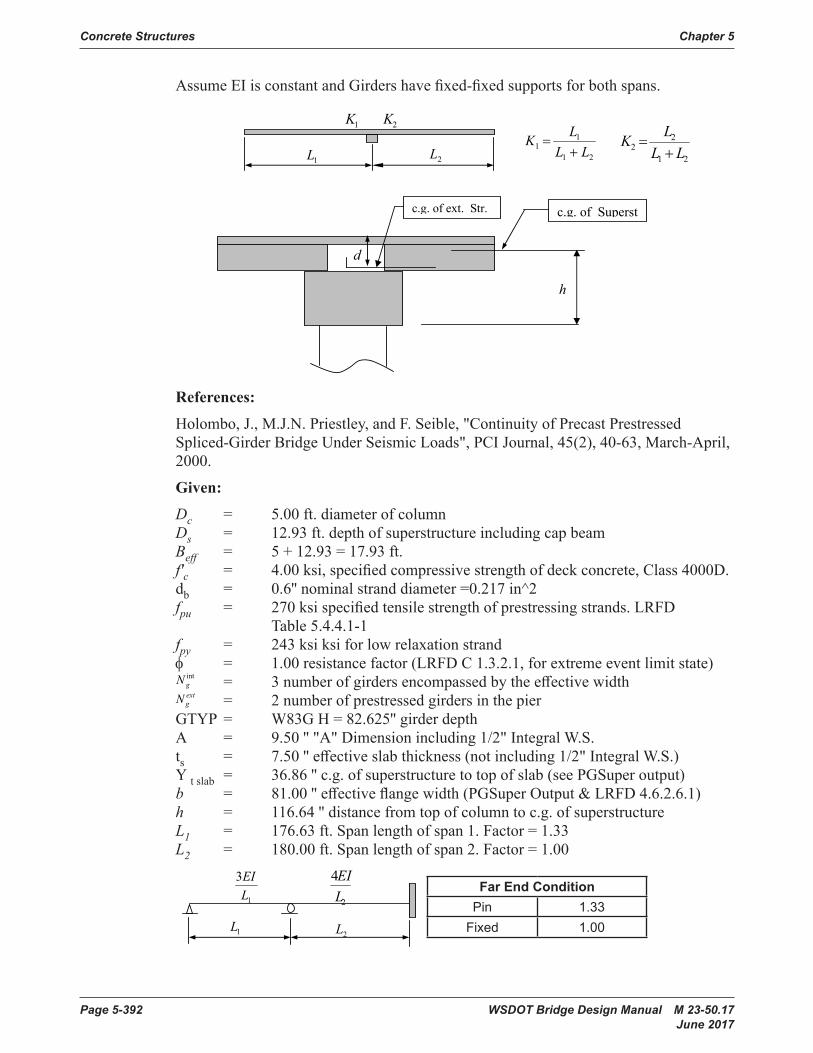
Concrete Structures Chapter 5
Page 5-392 WSDOT Bridge Design Manual M 23-50.17 June 2017
AssumeEIisconstantandGirdershavefixed-fixedsupportsforbothspans.AssumeEIisconstantandGirdershavefixed-fixedsupportsforbothspans.
References:
Holombo,J.,M.J.N.Priestley,andF.Seible,"ContinuityofPrecastPrestressedSpliced-GirderBridgeUnderSeismicLoads",PCIJournal, 45(2), 40-63, March-April, 2000.
Given:
= 5.00 ft. diameter of column
= 12.93 ft.depthofsuperstructureincludingcapbeam
= 5 + 12.93 = 17.93 ft.
= 4.00 ksi, specified compressive strength of deck concrete, Class 4000D.
= 0.6'' nominalstranddiameter=0.217in^2
= 270 ksi specified tensile strength of prestressing strands.
LRFDTable5.4.4.1-1
= 243 ksi ksi for low relaxation strand
= 1.00 resistance factor (LRFD C 1.3.2.1, for extreme event limit state)
= 3 numberofgirdersencompassedbytheeffectivewidth
= 2 numberofprestressedgirdersinthepier
c.g. of Superstc.g. of ext. Str.
h
d
1K 2K
1L 2L 21
11 LL
LK+
=21
22 LL
LK+
=
bd
'cf
puf
pyf
intgNextgN
φ
cD
sDeffB
Deleted: Numberofextendedstraightstrands needed to develop the required moment capacity at the end of girder is basedontheyieldstrengthofthestrands.¶<sp>¶¶¶<sp>where:¶<sp>= area of each extended strand, in^2¶= yield strength of prestressing steel specifiedinLRFDTable5.4.4.1-1¶<sp>= distancefromtopofslabtoc.g.ofextendedstrands,in.¶<sp><sp>= moment due to SIDL (trafficbarrier,sidewalk,etc.)pergirder¶= spanmomentdistributionfactor use maximumof(K1andK2)¶<sp>= flexuralresistancefactor¶
References:
Holombo,J.,M.J.N.Priestley,andF.Seible,"ContinuityofPrecastPrestressedSpliced-GirderBridgeUnderSeismicLoads",PCIJournal,45(2),40-63,March-April,2000.
Given:
Dc = 5.00 ft. diameter of column Ds = 12.93ft.depthofsuperstructureincludingcapbeam Beff = 5 + 12.93 = 17.93 ft. f'c = 4.00ksi,specifiedcompressivestrengthofdeckconcrete,Class4000D. db = 0.6''nominalstranddiameter=0.217in^2 fpu = 270ksispecifiedtensilestrengthofprestressingstrands.LRFD Table5.4.4.1-1 fpy = 243 ksi ksi for low relaxation strand φ = 1.00 resistance factor (LRFD C 1.3.2.1, for extreme event limit state)
AssumeEIisconstantandGirdershavefixed-fixedsupportsforbothspans.
References:
Holombo,J.,M.J.N.Priestley,andF.Seible,"ContinuityofPrecastPrestressedSpliced-GirderBridgeUnderSeismicLoads",PCIJournal, 45(2), 40-63, March-April, 2000.
Given:
= 5.00 ft. diameter of column
= 12.93 ft.depthofsuperstructureincludingcapbeam
= 5 + 12.93 = 17.93 ft.
= 4.00 ksi, specified compressive strength of deck concrete, Class 4000D.
= 0.6'' nominalstranddiameter=0.217in^2
= 270 ksi specified tensile strength of prestressing strands.
LRFDTable5.4.4.1-1
= 243 ksi ksi for low relaxation strand
= 1.00 resistance factor (LRFD C 1.3.2.1, for extreme event limit state)
= 3 numberofgirdersencompassedbytheeffectivewidth
= 2 numberofprestressedgirdersinthepier
c.g. of Superstc.g. of ext. Str.
h
d
1K 2K
1L 2L 21
11 LL
LK+
=21
22 LL
LK+
=
bd
'cf
puf
pyf
intgNextgN
φ
cD
sDeffB
Deleted: Numberofextendedstraightstrands needed to develop the required moment capacity at the end of girder is basedontheyieldstrengthofthestrands.¶<sp>¶¶¶<sp>where:¶<sp>= area of each extended strand, in^2¶= yield strength of prestressing steel specifiedinLRFDTable5.4.4.1-1¶<sp>= distancefromtopofslabtoc.g.ofextendedstrands,in.¶<sp><sp>= moment due to SIDL (trafficbarrier,sidewalk,etc.)pergirder¶= spanmomentdistributionfactor use maximumof(K1andK2)¶<sp>= flexuralresistancefactor¶
= 3numberofgirdersencompassedbytheeffectivewidth
AssumeEIisconstantandGirdershavefixed-fixedsupportsforbothspans.
References:
Holombo,J.,M.J.N.Priestley,andF.Seible,"ContinuityofPrecastPrestressedSpliced-GirderBridgeUnderSeismicLoads",PCIJournal, 45(2), 40-63, March-April, 2000.
Given:
= 5.00 ft. diameter of column
= 12.93 ft.depthofsuperstructureincludingcapbeam
= 5 + 12.93 = 17.93 ft.
= 4.00 ksi, specified compressive strength of deck concrete, Class 4000D.
= 0.6'' nominalstranddiameter=0.217in^2
= 270 ksi specified tensile strength of prestressing strands.
LRFDTable5.4.4.1-1
= 243 ksi ksi for low relaxation strand
= 1.00 resistance factor (LRFD C 1.3.2.1, for extreme event limit state)
= 3 numberofgirdersencompassedbytheeffectivewidth
= 2 numberofprestressedgirdersinthepier
c.g. of Superstc.g. of ext. Str.
h
d
1K 2K
1L 2L 21
11 LL
LK+
=21
22 LL
LK+
=
bd
'cf
puf
pyf
intgNextgN
φ
cD
sDeffB
Deleted: Numberofextendedstraightstrands needed to develop the required moment capacity at the end of girder is basedontheyieldstrengthofthestrands.¶<sp>¶¶¶<sp>where:¶<sp>= area of each extended strand, in^2¶= yield strength of prestressing steel specifiedinLRFDTable5.4.4.1-1¶<sp>= distancefromtopofslabtoc.g.ofextendedstrands,in.¶<sp><sp>= moment due to SIDL (trafficbarrier,sidewalk,etc.)pergirder¶= spanmomentdistributionfactor use maximumof(K1andK2)¶<sp>= flexuralresistancefactor¶
= 2numberofprestressedgirdersinthepier GTYP = W83GH=82.625''girderdepth A = 9.50''"A"Dimensionincluding1/2"IntegralW.S. ts = 7.50''effectiveslabthickness(notincluding1/2"IntegralW.S.) Y tslab = 36.86''c.g.ofsuperstructuretotopofslab(seePGSuperoutput) b = 81.00''effectiveflangewidth(PGSuperOutput&LRFD4.6.2.6.1) h = 116.64''distancefromtopofcolumntoc.g.ofsuperstructure L1 = 176.63 ft. Span length of span 1. Factor = 1.33 L2 = 180.00 ft. Span length of span 2. Factor = 1.00
= W83G H= 82.625'' girderdepth
A= 9.50'' "A"Dimensionincluding1/2"IntegralW.S.
7.50'' effectiveslabthickness(notincluding1/2"IntegralW.S.)
= 36.86'' c.g.ofsuperstructuretotopofslab(seePGSuperoutput)
= 81.00'' effectiveflangewidth(PGSuper Output & LRFD 4.6.2.6.1)
= 116.64'' distancefromtopofcolumntoc.g.ofsuperstructure
= 176.63 ft. Span length of span 1. Factor = 1.33
= 180.00 ft. Span length of span 2. Factor = 1.00
Far End Condition
Pin 1.33
Fixed 1.00
= 25.00 ft. column clear height used to determine overstrength shear associated with the overstrength moments, ft.
= 16000.0 plastic overstrength moment at top of column, kip-ft
= 16500.0plasticoverstrengthmomentatbaseofcolumn,kip-ft.
= 517.0 moment due to SIDL (traffic barrier,sidewalk,etc.)pergirder,
kip-ft (see QconBridge Output)
= 0.90
Design Steps:
Step 1: Calculate the design moment at the center of gravity of superstructure
= 16000 + ( 16000 + 16500 ) / 25 * 116.64 / 12 = 28636 kip-ft
Step 2: Calculate the design moment per girder.
= 2/3 * 28636 / 3 = 6363.56 kip-ft
= 1/3 * 28636 / 2 = 4772.67 kip-ft
= 28636 / (3 + 2 )= 5727.2 kip-ft = 6363.56 kip-ft.
= 234.92 ft. (Modified) = 180 / (234.92 + 180 ) = 0.434
1
3LEI
2
4LEI
1L2L
pγ
cL
toppoM
BasepoM
SIDLM
CGpoM
IntseiM
ExtseiM
AvgseiM
1L1K
GTYPE
t s =
slabtY
h
1L
2L
b
Far End ConditionPin 1 .33
Fixed 1 .00
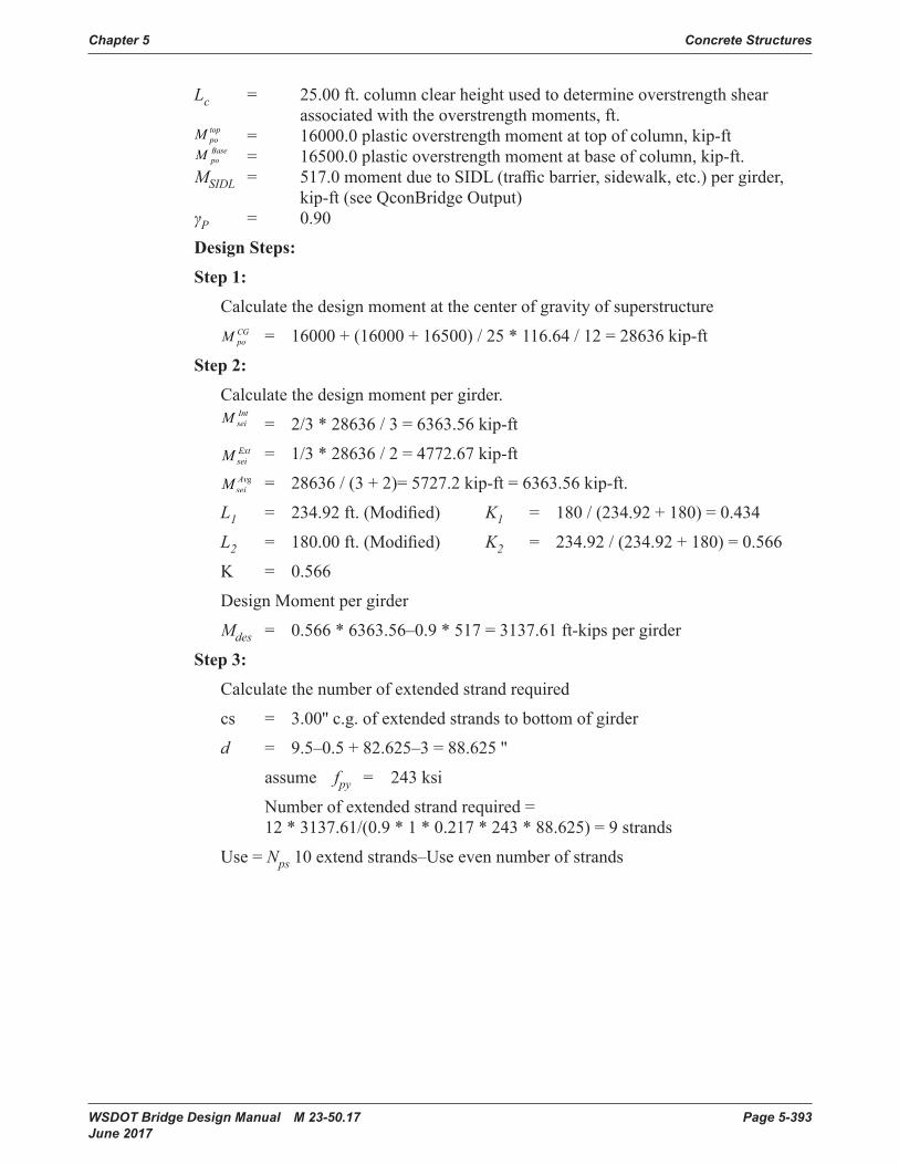
Chapter 5 Concrete Structures
WSDOT Bridge Design Manual M 23-50.17 Page 5-393 June 2017
Lc = 25.00 ft. column clear height used to determine overstrength shear associated with the overstrength moments, ft.
= W83G H= 82.625'' girderdepth
A= 9.50'' "A"Dimensionincluding1/2"IntegralW.S.
7.50'' effectiveslabthickness(notincluding1/2"IntegralW.S.)
= 36.86'' c.g.ofsuperstructuretotopofslab(seePGSuperoutput)
= 81.00'' effectiveflangewidth(PGSuper Output & LRFD 4.6.2.6.1)
= 116.64'' distancefromtopofcolumntoc.g.ofsuperstructure
= 176.63 ft. Span length of span 1. Factor = 1.33
= 180.00 ft. Span length of span 2. Factor = 1.00
Far End Condition
Pin 1.33
Fixed 1.00
= 25.00 ft. column clear height used to determine overstrength shear associated with the overstrength moments, ft.
= 16000.0 plastic overstrength moment at top of column, kip-ft
= 16500.0plasticoverstrengthmomentatbaseofcolumn,kip-ft.
= 517.0 moment due to SIDL (traffic barrier,sidewalk,etc.)pergirder,
kip-ft (see QconBridge Output)
= 0.90
Design Steps:
Step 1: Calculate the design moment at the center of gravity of superstructure
= 16000 + ( 16000 + 16500 ) / 25 * 116.64 / 12 = 28636 kip-ft
Step 2: Calculate the design moment per girder.
= 2/3 * 28636 / 3 = 6363.56 kip-ft
= 1/3 * 28636 / 2 = 4772.67 kip-ft
= 28636 / (3 + 2 )= 5727.2 kip-ft = 6363.56 kip-ft.
= 234.92 ft. (Modified) = 180 / (234.92 + 180 ) = 0.434
1
3LEI
2
4LEI
1L2L
pγ
cL
toppoM
BasepoM
SIDLM
CGpoM
IntseiM
ExtseiM
AvgseiM
1L1K
GTYPE
t s =
slabtY
h
1L
2L
b
= 16000.0 plastic overstrength moment at top of column, kip-ft
= W83G H= 82.625'' girderdepth
A= 9.50'' "A"Dimensionincluding1/2"IntegralW.S.
7.50'' effectiveslabthickness(notincluding1/2"IntegralW.S.)
= 36.86'' c.g.ofsuperstructuretotopofslab(seePGSuperoutput)
= 81.00'' effectiveflangewidth(PGSuper Output & LRFD 4.6.2.6.1)
= 116.64'' distancefromtopofcolumntoc.g.ofsuperstructure
= 176.63 ft. Span length of span 1. Factor = 1.33
= 180.00 ft. Span length of span 2. Factor = 1.00
Far End Condition
Pin 1.33
Fixed 1.00
= 25.00 ft. column clear height used to determine overstrength shear associated with the overstrength moments, ft.
= 16000.0 plastic overstrength moment at top of column, kip-ft
= 16500.0plasticoverstrengthmomentatbaseofcolumn,kip-ft.
= 517.0 moment due to SIDL (traffic barrier,sidewalk,etc.)pergirder,
kip-ft (see QconBridge Output)
= 0.90
Design Steps:
Step 1: Calculate the design moment at the center of gravity of superstructure
= 16000 + ( 16000 + 16500 ) / 25 * 116.64 / 12 = 28636 kip-ft
Step 2: Calculate the design moment per girder.
= 2/3 * 28636 / 3 = 6363.56 kip-ft
= 1/3 * 28636 / 2 = 4772.67 kip-ft
= 28636 / (3 + 2 )= 5727.2 kip-ft = 6363.56 kip-ft.
= 234.92 ft. (Modified) = 180 / (234.92 + 180 ) = 0.434
1
3LEI
2
4LEI
1L2L
pγ
cL
toppoM
BasepoM
SIDLM
CGpoM
IntseiM
ExtseiM
AvgseiM
1L1K
GTYPE
t s =
slabtY
h
1L
2L
b
= 16500.0plasticoverstrengthmomentatbaseofcolumn,kip-ft. MSIDL = 517.0momentduetoSIDL(trafficbarrier,sidewalk,etc.)pergirder, kip-ft (see QconBridge Output) γP = 0.90
Design Steps:
Step 1:
Calculate the design moment at the center of gravity of superstructure
= W83G H= 82.625'' girderdepth
A= 9.50'' "A"Dimensionincluding1/2"IntegralW.S.
7.50'' effectiveslabthickness(notincluding1/2"IntegralW.S.)
= 36.86'' c.g.ofsuperstructuretotopofslab(seePGSuperoutput)
= 81.00'' effectiveflangewidth(PGSuper Output & LRFD 4.6.2.6.1)
= 116.64'' distancefromtopofcolumntoc.g.ofsuperstructure
= 176.63 ft. Span length of span 1. Factor = 1.33
= 180.00 ft. Span length of span 2. Factor = 1.00
Far End Condition
Pin 1.33
Fixed 1.00
= 25.00 ft. column clear height used to determine overstrength shear associated with the overstrength moments, ft.
= 16000.0 plastic overstrength moment at top of column, kip-ft
= 16500.0plasticoverstrengthmomentatbaseofcolumn,kip-ft.
= 517.0 moment due to SIDL (traffic barrier,sidewalk,etc.)pergirder,
kip-ft (see QconBridge Output)
= 0.90
Design Steps:
Step 1: Calculate the design moment at the center of gravity of superstructure
= 16000 + ( 16000 + 16500 ) / 25 * 116.64 / 12 = 28636 kip-ft
Step 2: Calculate the design moment per girder.
= 2/3 * 28636 / 3 = 6363.56 kip-ft
= 1/3 * 28636 / 2 = 4772.67 kip-ft
= 28636 / (3 + 2 )= 5727.2 kip-ft = 6363.56 kip-ft.
= 234.92 ft. (Modified) = 180 / (234.92 + 180 ) = 0.434
1
3LEI
2
4LEI
1L2L
pγ
cL
toppoM
BasepoM
SIDLM
CGpoM
IntseiM
ExtseiM
AvgseiM
1L1K
GTYPE
t s =
slabtY
h
1L
2L
b
= 16000 + (16000 + 16500) / 25 * 116.64 / 12 = 28636 kip-ft
Step 2:
Calculate the design moment per girder.
= W83G H= 82.625'' girderdepth
A= 9.50'' "A"Dimensionincluding1/2"IntegralW.S.
7.50'' effectiveslabthickness(notincluding1/2"IntegralW.S.)
= 36.86'' c.g.ofsuperstructuretotopofslab(seePGSuperoutput)
= 81.00'' effectiveflangewidth(PGSuper Output & LRFD 4.6.2.6.1)
= 116.64'' distancefromtopofcolumntoc.g.ofsuperstructure
= 176.63 ft. Span length of span 1. Factor = 1.33
= 180.00 ft. Span length of span 2. Factor = 1.00
Far End Condition
Pin 1.33
Fixed 1.00
= 25.00 ft. column clear height used to determine overstrength shear associated with the overstrength moments, ft.
= 16000.0 plastic overstrength moment at top of column, kip-ft
= 16500.0plasticoverstrengthmomentatbaseofcolumn,kip-ft.
= 517.0 moment due to SIDL (traffic barrier,sidewalk,etc.)pergirder,
kip-ft (see QconBridge Output)
= 0.90
Design Steps:
Step 1: Calculate the design moment at the center of gravity of superstructure
= 16000 + ( 16000 + 16500 ) / 25 * 116.64 / 12 = 28636 kip-ft
Step 2: Calculate the design moment per girder.
= 2/3 * 28636 / 3 = 6363.56 kip-ft
= 1/3 * 28636 / 2 = 4772.67 kip-ft
= 28636 / (3 + 2 )= 5727.2 kip-ft = 6363.56 kip-ft.
= 234.92 ft. (Modified) = 180 / (234.92 + 180 ) = 0.434
1
3LEI
2
4LEI
1L2L
pγ
cL
toppoM
BasepoM
SIDLM
CGpoM
IntseiM
ExtseiM
AvgseiM
1L1K
GTYPE
t s =
slabtY
h
1L
2L
b
= 2/3 * 28636 / 3 = 6363.56 kip-ft
= W83G H= 82.625'' girderdepth
A= 9.50'' "A"Dimensionincluding1/2"IntegralW.S.
7.50'' effectiveslabthickness(notincluding1/2"IntegralW.S.)
= 36.86'' c.g.ofsuperstructuretotopofslab(seePGSuperoutput)
= 81.00'' effectiveflangewidth(PGSuper Output & LRFD 4.6.2.6.1)
= 116.64'' distancefromtopofcolumntoc.g.ofsuperstructure
= 176.63 ft. Span length of span 1. Factor = 1.33
= 180.00 ft. Span length of span 2. Factor = 1.00
Far End Condition
Pin 1.33
Fixed 1.00
= 25.00 ft. column clear height used to determine overstrength shear associated with the overstrength moments, ft.
= 16000.0 plastic overstrength moment at top of column, kip-ft
= 16500.0plasticoverstrengthmomentatbaseofcolumn,kip-ft.
= 517.0 moment due to SIDL (traffic barrier,sidewalk,etc.)pergirder,
kip-ft (see QconBridge Output)
= 0.90
Design Steps:
Step 1: Calculate the design moment at the center of gravity of superstructure
= 16000 + ( 16000 + 16500 ) / 25 * 116.64 / 12 = 28636 kip-ft
Step 2: Calculate the design moment per girder.
= 2/3 * 28636 / 3 = 6363.56 kip-ft
= 1/3 * 28636 / 2 = 4772.67 kip-ft
= 28636 / (3 + 2 )= 5727.2 kip-ft = 6363.56 kip-ft.
= 234.92 ft. (Modified) = 180 / (234.92 + 180 ) = 0.434
1
3LEI
2
4LEI
1L2L
pγ
cL
toppoM
BasepoM
SIDLM
CGpoM
IntseiM
ExtseiM
AvgseiM
1L1K
GTYPE
t s =
slabtY
h
1L
2L
b
= 1/3 * 28636 / 2 = 4772.67 kip-ft
= W83G H= 82.625'' girderdepth
A= 9.50'' "A"Dimensionincluding1/2"IntegralW.S.
7.50'' effectiveslabthickness(notincluding1/2"IntegralW.S.)
= 36.86'' c.g.ofsuperstructuretotopofslab(seePGSuperoutput)
= 81.00'' effectiveflangewidth(PGSuper Output & LRFD 4.6.2.6.1)
= 116.64'' distancefromtopofcolumntoc.g.ofsuperstructure
= 176.63 ft. Span length of span 1. Factor = 1.33
= 180.00 ft. Span length of span 2. Factor = 1.00
Far End Condition
Pin 1.33
Fixed 1.00
= 25.00 ft. column clear height used to determine overstrength shear associated with the overstrength moments, ft.
= 16000.0 plastic overstrength moment at top of column, kip-ft
= 16500.0plasticoverstrengthmomentatbaseofcolumn,kip-ft.
= 517.0 moment due to SIDL (traffic barrier,sidewalk,etc.)pergirder,
kip-ft (see QconBridge Output)
= 0.90
Design Steps:
Step 1: Calculate the design moment at the center of gravity of superstructure
= 16000 + ( 16000 + 16500 ) / 25 * 116.64 / 12 = 28636 kip-ft
Step 2: Calculate the design moment per girder.
= 2/3 * 28636 / 3 = 6363.56 kip-ft
= 1/3 * 28636 / 2 = 4772.67 kip-ft
= 28636 / (3 + 2 )= 5727.2 kip-ft = 6363.56 kip-ft.
= 234.92 ft. (Modified) = 180 / (234.92 + 180 ) = 0.434
1
3LEI
2
4LEI
1L2L
pγ
cL
toppoM
BasepoM
SIDLM
CGpoM
IntseiM
ExtseiM
AvgseiM
1L1K
GTYPE
t s =
slabtY
h
1L
2L
b
= 28636 / (3 + 2)= 5727.2 kip-ft = 6363.56 kip-ft.
L1 = 234.92ft.(Modified) K1 = 180 / (234.92 + 180) = 0.434
L2 = 180.00ft.(Modified) K2 = 234.92 / (234.92 + 180) = 0.566
K = 0.566
Design Moment per girder
Mdes = 0.566 * 6363.56–0.9 * 517 = 3137.61 ft-kips per girder
Step 3:
Calculatethenumberofextendedstrandrequired
cs = 3.00''c.g.ofextendedstrandstobottomofgirder
d = 9.5–0.5+82.625–3=88.625''
assume fpy = 243 ksi
Numberofextendedstrandrequired= 12 * 3137.61/(0.9 * 1 * 0.217 * 243 * 88.625) = 9 strands
Use = Nps 10extendstrands–Useevennumberofstrands

Concrete Structures Chapter 5
Page 5-394 WSDOT Bridge Design Manual M 23-50.17 June 2017
Step 4:
Check moment capacity of extended strands
cs = 3.00''c.g.ofextendedstrandstobottomofgirder
PerLRFD5.7.3.2Thefactoredflexuralresistance
Mr = φ Mn Mn = Aps fpy (dp–a 2 )
where:
Aps = area of prestressing steel, in^2 . =10 * 0 .217 = 2 .17 in^2 dp = distance from extreme compression fiber to the centroid of prestressing tendons (in .) dp = 9 .5–0 .5 + 82 .625–3 = 88 .625''
Assumerectangularbehavior:Assumerectangularbehavior:
for
for
= 4.00 ksi = 1.3 * 4 = 5.2 ksi = 0.79
= 2.17*243/0.85*5.2*0.79*81=1.864''
= 0.79*1.864=1.473'' depthoftheequivalentstressblock(in.)
= 2.17 * 243 * ( 88.625 - 1.473 / 2 )/12 = 3862.04 kip-ft.
= 1*3862.04=3862.04kip-ft. >=3137.61ft-kips OK
bffA
cce
pyps
1'85.0 β
=
'cef
1β'cf
ca
nM
rM
85.01 =β psifce 4000' ≤
65.01000
400005.085.0'
1 ≥−=-fceβ psifce 4000' >
fc = 4.00 ksi = 1.3 * 4 = 5.2 ksi = 0.79
c = 2.17*243/0.85*5.2*0.79*81=1.864''
a = 0.79*1.864=1.473''depthoftheequivalentstressblock(in.)
Mn = 2.17 * 243 * (88.625–1.473/2)/12 = 3862.04 kip-ft.
Mr = 1*3862.04=3862.04kip-ft.>=3137.61ft-kipsOK

WSDOT Bridge Design Manual M 23-50.17 Page 5-395 June 2017
LRFD Wingwall Design Appendix 5-B11 Vehicle Collision
Collision Load Factor § Table 3.4.1-1 LRFD AASHTO
γEH 1.35:= Horizontal Earth Load Factor § Table 3.4.1-2 LRFD AASHTO
γLS 0.5:= Live Load Surcharge Load Factor
for Extreme Event II
§ Table 3.4.1-2 LRFD AASHTO
Transverse Collision Force Moment Arm
MomentArm LLt
2−:= MomentArm 13.25 ft=
Wall Height at Abutment
H hL
GroundSlope
+:= H 10.00ft=
Flexural Moment due to Collision Load and Earth Pressure
FlexuralMoment γCT Ft⋅ MomentArm⋅ γEHW L
2⋅
24⋅ 3 h
2⋅ H 4 S⋅
γLS
γEH
⋅+
H 2 h⋅+( )⋅+
⋅+:=
FlexuralMoment 836.92 kip ft⋅=
MuFlexuralMoment
H:= Mu 83.69
kip ft⋅
ft=
LRFD Wingwall Design - Vehicle Collision
Problem Description: A wingwall with traffic barrier is to be checked for moment capacity at a
vertical section at the abutment for a vehicular impact.
AASHTO LRFD Specifications Extreme Event-II Limit State (Test Level TL-4)
L 15ft:= Wingwall Length
h 2.5ft:= Height of wingwall at end away from pier.
S 2ft:= Traffic surcharge (given in height of soil above road). See LRFD Tables
3.11.6.4-1 and 3.11.6.4-2.
GroundSlope 2:= to 1
W 45lbf
ft2
ft⋅
⋅:= Lateral Earth Pressure (equilivant fluid pressure per foot)
Ft 54kip:= Transverse Collision Load § Table A13.2-1 LRFD AASHTO
Lt 3.5ft:= Collision Dist. Width § Table A13.2-1 LRFD AASHTO
γCT 1:=

Concrete Structures Chapter 5
Page 5-396 WSDOT Bridge Design Manual M 23-50.17 June 2017
Collision Load Factor § Table 3.4.1-1 LRFD AASHTO
γEH 1.35:= Horizontal Earth Load Factor § Table 3.4.1-2 LRFD AASHTO
γLS 0.5:= Live Load Surcharge Load Factor
for Extreme Event II
§ Table 3.4.1-2 LRFD AASHTO
Transverse Collision Force Moment Arm
MomentArm LLt
2−:= MomentArm 13.25 ft=
Wall Height at Abutment
H hL
GroundSlope
+:= H 10.00ft=
Flexural Moment due to Collision Load and Earth Pressure
FlexuralMoment γCT Ft⋅ MomentArm⋅ γEHW L
2⋅
24⋅ 3 h
2⋅ H 4 S⋅
γLS
γEH
⋅+
H 2 h⋅+( )⋅+
⋅+:=
FlexuralMoment 836.92 kip ft⋅=
MuFlexuralMoment
H:= Mu 83.69
kip ft⋅
ft=
LRFD Wingwall Design - Vehicle Collision
Problem Description: A wingwall with traffic barrier is to be checked for moment capacity at a
vertical section at the abutment for a vehicular impact.
AASHTO LRFD Specifications Extreme Event-II Limit State (Test Level TL-4)
L 15ft:= Wingwall Length
h 2.5ft:= Height of wingwall at end away from pier.
S 2ft:= Traffic surcharge (given in height of soil above road). See LRFD Tables
3.11.6.4-1 and 3.11.6.4-2.
GroundSlope 2:= to 1
W 45lbf
ft2
ft⋅
⋅:= Lateral Earth Pressure (equilivant fluid pressure per foot)
Ft 54kip:= Transverse Collision Load § Table A13.2-1 LRFD AASHTO
Lt 3.5ft:= Collision Dist. Width § Table A13.2-1 LRFD AASHTO
γCT 1:=

Chapter 5 Concrete Structures
WSDOT Bridge Design Manual M 23-50.17 Page 5-397 June 2017
Define Units ksi 1000 psi⋅≡ kip 1000 lbf⋅≡ kcf kip ft3−
⋅≡ klf 1000 lbf⋅ ft1−
⋅≡
MPa Pa 106
⋅≡ N 1 newton⋅≡ kN 1000 N⋅≡
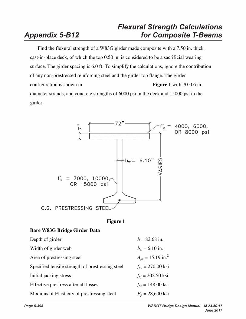
Page 5-398 WSDOT Bridge Design Manual M 23-50.17 June 2017
Flexural Strength Calculations Appendix 5-B12 for Composite T-Beams
1
FLEXURAL STRENGTH CALCULATIONS for COMPOSITE T-BEAMS
Find the flexural strength of a W83G girder made composite with a 7.50 in. thick
cast-in-place deck, of which the top 0.50 in. is considered to be a sacrificial wearing
surface. The girder spacing is 6.0 ft. To simplify the calculations, ignore the contribution
of any non-prestressed reinforcing steel and the girder top flange. The girder
configuration is shown in Figure 1 with 70-0.6 in.
diameter strands, and concrete strengths of 6000 psi in the deck and 15000 psi in the
girder.
Figure 1
Bare W83G Bridge Girder Data
Depth of girder h = 82.68 in.
Width of girder web bw = 6.10 in.
Area of prestressing steel Aps = 15.19 in.2
Specified tensile strength of prestressing steel fpu = 270.00 ksi
Initial jacking stress fpj = 202.50 ksi
Effective prestress after all losses fpe = 148.00 ksi
Modulus of Elasticity of prestressing steel Ep = 28,600 ksi
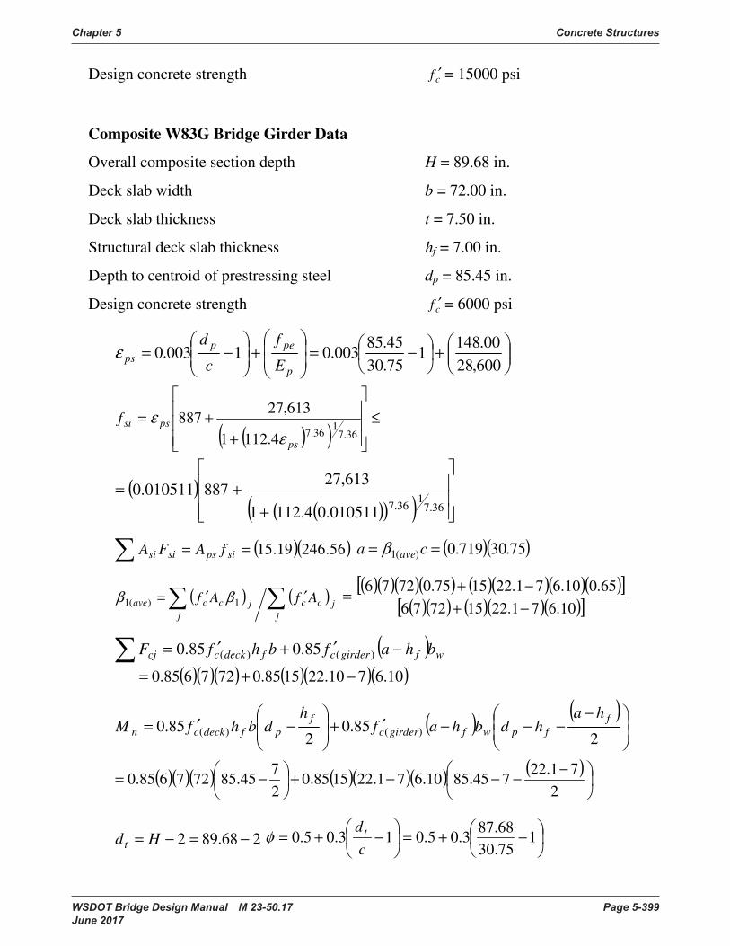
Chapter 5 Concrete Structures
WSDOT Bridge Design Manual M 23-50.17 Page 5-399 June 2017
2
Design concrete strength cf ′ = 15000 psi
Composite W83G Bridge Girder Data
Overall composite section depth H = 89.68 in.
Deck slab width b = 72.00 in.
Deck slab thickness t = 7.50 in.
Structural deck slab thickness hf = 7.00 in.
Depth to centroid of prestressing steel dp = 85.45 in.
Design concrete strength cf ′ = 6000 psi
+
−=
+
−=
600,2800.148
175.3045.85
003.01003.0p
pepps E
f
c
dε
( )( )≤
++=
36.71
36.74.1121
613,27887
ps
pssifε
ε
( )( )( )( )
++=
36.71
36.7010511.04.1121
613,27887010511.0
( )( )56.24619.15== sipssisi fAFA ( )( )75.30719.0)(1 == ca aveβ
( ) ( ) ′′=j
jccj
jccave AfAf 1)(1 ββ( )( )( )( ) ( )( )( )( )[ ]
( )( ) ( )( )( )[ ]10.671.2215727665.010.671.221575.07276
−+−+=
( ) wfgirdercfdeckccj bhafbhfF −′+′= )()( 85.085.0
( )( )( ) ( )( )( )10.6710.221585.0727685.0 −+=
( ) ( )
−−−−′+
−′=
285.0
285.0 )()(
ffpwfgirderc
fpfdeckcn
hahdbhaf
hdbhfM
( )( )( ) ( )( )( ) ( )
−−−−+
−=
271.22
745.8510.671.221585.027
45.85727685.0
268.892 −=−= Hdt
−+=
−+= 175.3068.87
3.05.013.05.0cdtφ
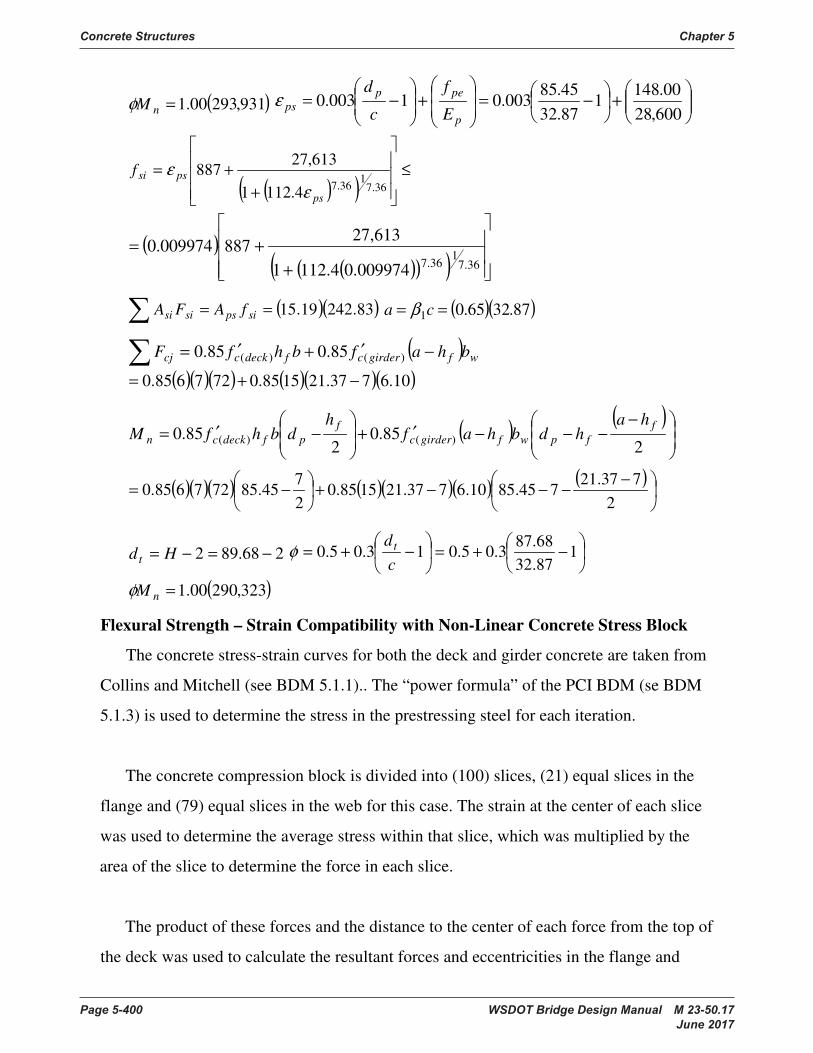
Concrete Structures Chapter 5
Page 5-400 WSDOT Bridge Design Manual M 23-50.17 June 2017
3
( )931,29300.1=nMφ
+
−=
+
−=
600,2800.148
187.3245.85
003.01003.0p
pepps E
f
c
dε
( )( )≤
++=
36.71
36.74.1121
613,27887
ps
pssifε
ε
( )( )( )( )
++=
36.71
36.7009974.04.1121
613,27887009974.0
( )( )83.24219.15== sipssisi fAFA ( )( )87.3265.01 == ca β
( ) wfgirdercfdeckccj bhafbhfF −′+′= )()( 85.085.0
( )( )( ) ( )( )( )10.6737.211585.0727685.0 −+=
( ) ( )
−−−−′+
−′=
285.0
285.0 )()(
ffpwfgirderc
fpfdeckcn
hahdbhaf
hdbhfM
( )( )( ) ( )( )( ) ( )
−−−−+
−=
2737.21
745.8510.6737.211585.027
45.85727685.0
268.892 −=−= Hdt
−+=
−+= 187.3268.87
3.05.013.05.0cdtφ
( )323,29000.1=nMφ
Flexural Strength – Strain Compatibility with Non-Linear Concrete Stress Block
The concrete stress-strain curves for both the deck and girder concrete are taken from
Collins and Mitchell (see BDM 5.1.1).. The “power formula” of the PCI BDM (se BDM
5.1.3) is used to determine the stress in the prestressing steel for each iteration.
The concrete compression block is divided into (100) slices, (21) equal slices in the
flange and (79) equal slices in the web for this case. The strain at the center of each slice
was used to determine the average stress within that slice, which was multiplied by the
area of the slice to determine the force in each slice.
The product of these forces and the distance to the center of each force from the top of
the deck was used to calculate the resultant forces and eccentricities in the flange and

Chapter 5 Concrete Structures
WSDOT Bridge Design Manual M 23-50.17 Page 5-401 June 2017 4
web. Example calculations for the stresses in the slice at the top of the deck, at the
interface between the deck and girder, and the prestressing steel are as follows:
For the deck concrete,
( ) ( )1000
000,000,16000000,401000
000,000,1000,40 +=+′
= cc
fE
= 4098 ksi
25006000
8.02500
8.0 +=′
+= cfn = 3.20
90006000
67.09000
67.0 +=′
+= cfk = 1.337
12.32.3
40986000
11000
−=
−′
=×′n
nEf
c
ccε = 2.129
For the top slice of deck,
( )2217=y = 0.167 in.
( ) ( )167.042.3442.34
003.0003.0 −=−= ycccfε = 0.002985
( ) ( )( ) ( ) ( )
( ) ( )337.12.3002129.0002985.012.3
002129.0002985.02.36
1 +−=
′+−
′′=
nkccf
ccfcc
n
nff
εε
εε
= 4.18 ksi (28.8 MPa)
The contribution of this slice to the overall resultant compressive force is
( )( ) kipininksiC 32.100217
7218.41 =
=
For bottom slice of deck,
( ) ( )2217
20217 +=y = 6.833 in.
( ) ( )833.642.3442.34
003.0003.0 −=−= ycccfε = 0.002404
( ) ( )( ) ( ) ( )
( ) ( )337.12.3002129.0002404.012.3
002129.0002404.02.36
1 +−=
′+−
′′=
nkccf
ccfcc
n
nff
εε
εε
= 5.59 ksi
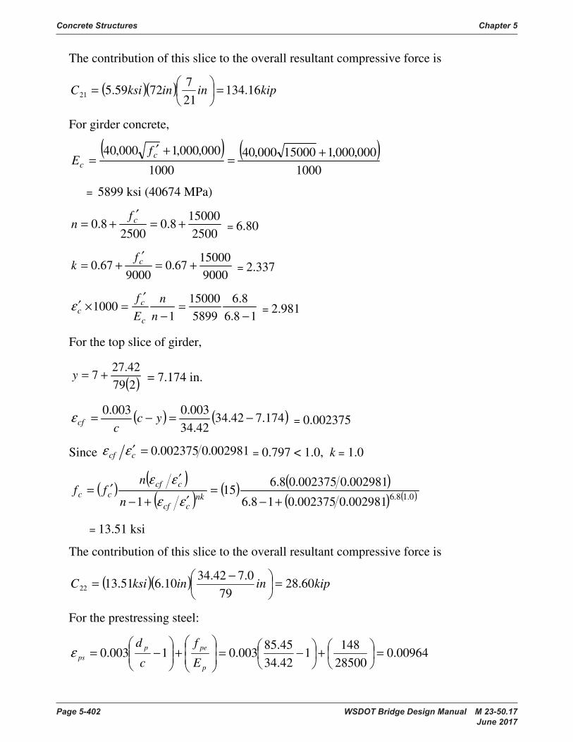
Concrete Structures Chapter 5
Page 5-402 WSDOT Bridge Design Manual M 23-50.17 June 2017
5
The contribution of this slice to the overall resultant compressive force is
( )( ) kipininksiC 16.134217
7259.521 =
=
For girder concrete,
( ) ( )1000
000,000,115000000,401000
000,000,1000,40 +=+′
= cc
fE
= 5899 ksi (40674 MPa)
250015000
8.02500
8.0 +=′
+= cfn = 6.80
900015000
67.09000
67.0 +=′
+= cfk = 2.337
18.68.6
589915000
11000
−=
−′
=×′n
nEf
c
ccε = 2.981
For the top slice of girder,
( )27942.27
7 +=y = 7.174 in.
( ) ( )174.742.3442.34
003.0003.0 −=−= ycccfε = 0.002375
Since 002981.0002375.0=′ccf εε = 0.797 < 1.0, k = 1.0
( ) ( )( ) ( ) ( )
( ) ( )0.18.6002981.0002375.018.6
002981.0002375.08.615
1 +−=
′+−
′′=
nkccf
ccfcc
n
nff
εε
εε
= 13.51 ksi
The contribution of this slice to the overall resultant compressive force is
( )( ) kipininksiC 60.2879
0.742.3410.651.1322 =
−=
For the prestressing steel:
00964.028500148
142.3445.85
003.01003.0 =
+
−=
+
−=
p
pepps E
f
c
dε
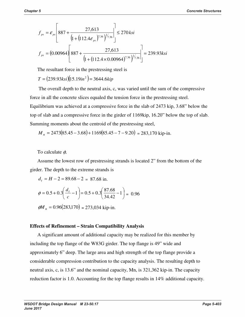
Chapter 5 Concrete Structures
WSDOT Bridge Design Manual M 23-50.17 Page 5-403 June 2017
6
( )( )
( )( )( )
ksif
ksif
ps
ps
psps
93.23900964.04.1121
613,2788700964.0
2704.1121
613,27887
36.7136.7
36.7136.7
=
×++=
≤
++=
εε
The resultant force in the prestressing steel is
( )( ) kipinksiT 6.364419.1593.239 2 ==
The overall depth to the neutral axis, c, was varied until the sum of the compressive
force in all the concrete slices equaled the tension force in the prestressing steel.
Equilibrium was achieved at a compressive force in the slab of 2473 kip, 3.68” below the
top of slab and a compressive force in the girder of 1169kip, 16.20” below the top of slab.
Summing moments about the centroid of the prestressing steel,
( ) ( )20.9745.85116968.345.852473 −−+−=nM = 283,170 kip-in.
To calculate φ,
Assume the lowest row of prestressing strands is located 2” from the bottom of the
girder. The depth to the extreme strands is
268.892 −=−= Hdt = 87.68 in.
−+=
−+= 142.3468.87
3.05.013.05.0cdtφ = 0.96
( )170,28396.0=nMφ = 273,034 kip-in.
Effects of Refinement – Strain Compatibility Analysis
A significant amount of additional capacity may be realized for this member by
including the top flange of the W83G girder. The top flange is 49” wide and
approximately 6” deep. The large area and high strength of the top flange provide a
considerable compression contribution to the capacity analysis. The resulting depth to
neutral axis, c, is 13.6” and the nominal capacity, Mn, is 321,362 kip-in. The capacity
reduction factor is 1.0. Accounting for the top flange results in 14% additional capacity.
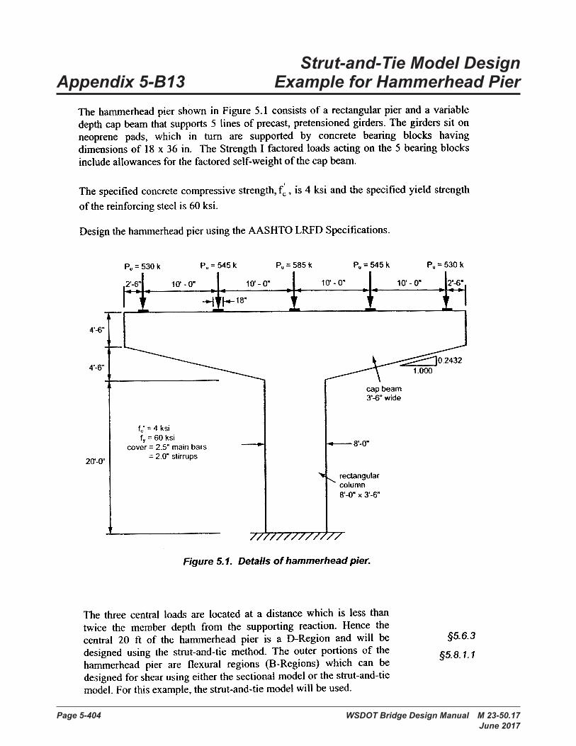
Page 5-404 WSDOT Bridge Design Manual M 23-50.17 June 2017
Strut-and-Tie Model Design Appendix 5-B13 Example for Hammerhead Pier

Chapter 5 Concrete Structures
WSDOT Bridge Design Manual M 23-50.17 Page 5-405 June 2017
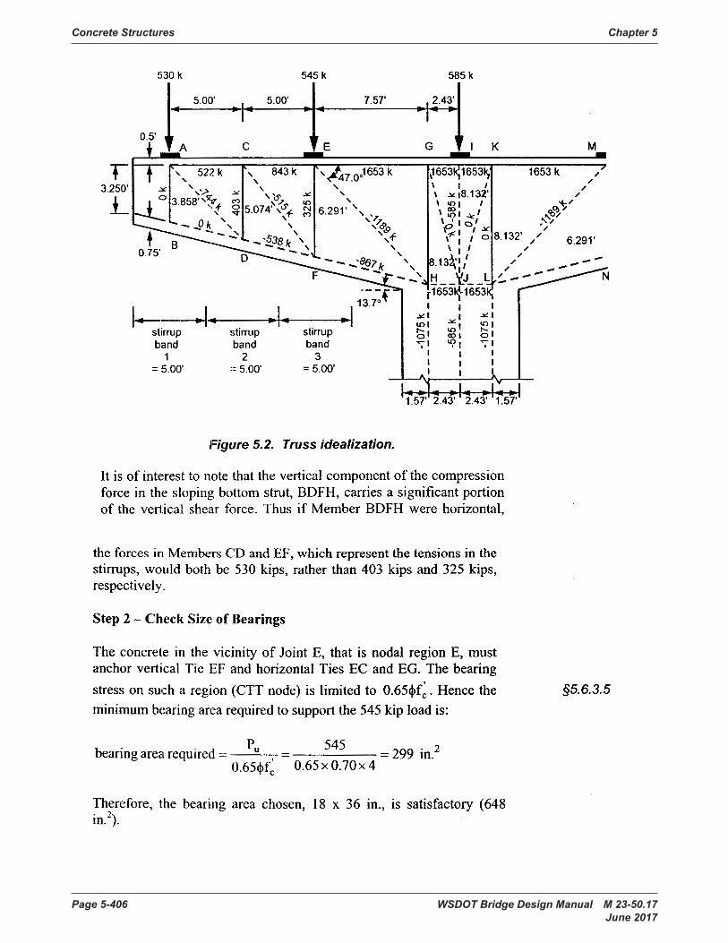
Concrete Structures Chapter 5
Page 5-406 WSDOT Bridge Design Manual M 23-50.17 June 2017
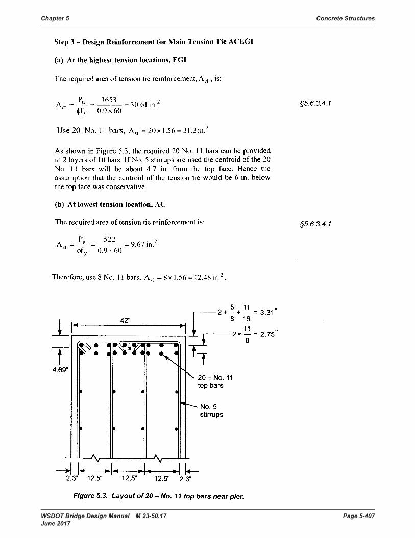
Chapter 5 Concrete Structures
WSDOT Bridge Design Manual M 23-50.17 Page 5-407 June 2017
Concrete Structures Chapter 5
Page 5-408 WSDOT Bridge Design Manual M 23-50.17 June 2017
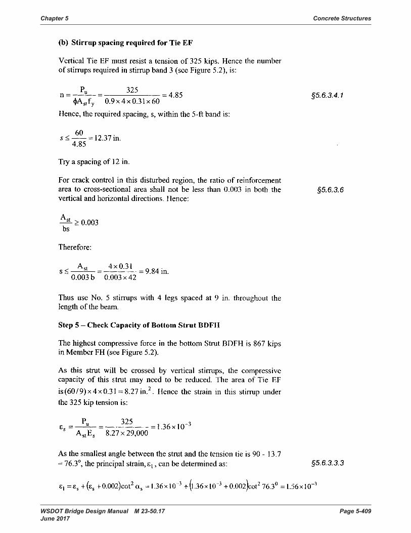
Chapter 5 Concrete Structures
WSDOT Bridge Design Manual M 23-50.17 Page 5-409 June 2017
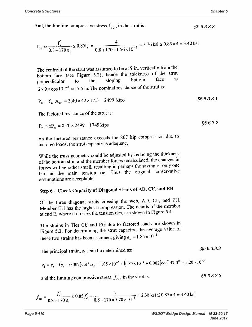
Concrete Structures Chapter 5
Page 5-410 WSDOT Bridge Design Manual M 23-50.17 June 2017

Chapter 5 Concrete Structures
WSDOT Bridge Design Manual M 23-50.17 Page 5-411 June 2017

Concrete Structures Chapter 5
Page 5-412 WSDOT Bridge Design Manual M 23-50.17 June 2017

WSDOT Bridge Design Manual M 23-50.17 Page 5-413 June 2017
Shear and Torsion Capacity Appendix 5-B14 of a Reinforced Concrete Beam
Spacing of Transverse Reinforcements 5 in⋅:=
TransversebarT 6:=
Longitudinal - BottombarLB 18:=
Longitudinal - TopbarLT 18:=
LRFD 5.4.4.2 for strandsEp 28500ksi:=
LRFD 5.4.3.2Es 29000ksi:=
fy 40 ksi⋅:=
Ab bar( ) 0.11 in2⋅ bar 3=if
0.20 in2⋅ bar 4=if
0.31 in2⋅ bar 5=if
0.44 in2⋅ bar 6=if
0.60 in2⋅ bar 7=if
0.79 in2⋅ bar 8=if
1.00 in2⋅ bar 9=if
1.27 in2⋅ bar 10=if
1.56 in2⋅ bar 11=if
2.25 in2⋅ bar 14=if
4.00 in2⋅ bar 18=if
:=dia bar( ) 0.375 in⋅ bar 3=if
0.500 in⋅ bar 4=if
0.625 in⋅ bar 5=if
0.750 in⋅ bar 6=if
0.875in bar 7=if
1.000in bar 8=if
1.128in bar 9=if
1.270in bar 10=if
1.410in bar 11=if
1.693in bar 14=if
2.257in bar 18=if
:=
Bar Areas:Bar Diameters:
Reinforcement Properties:
f'c 4 ksi⋅:=
Concrete Properties:
Find the torsion and shear capacity of a reinforced concrete beam of width 37in and height 90in. Clear cover for all sides equals 1.625in. Shear and torsion reinforcement consists of #6 stirrups spaced at 5in. Longitudinal moment steel consists of 4 #18 bars in one row in the top and in the bottom. Factored loads are Vu = 450 kips and Tu = 500 kip-ft.
Problem Description:
klf kip ft 1−⋅≡kcf kip ft 3−
⋅≡kip 1000 lbf⋅≡ksi 1000 psi⋅≡
Define Units:
Shear and Torsion Capacity of a Reinforced Concrete Beam
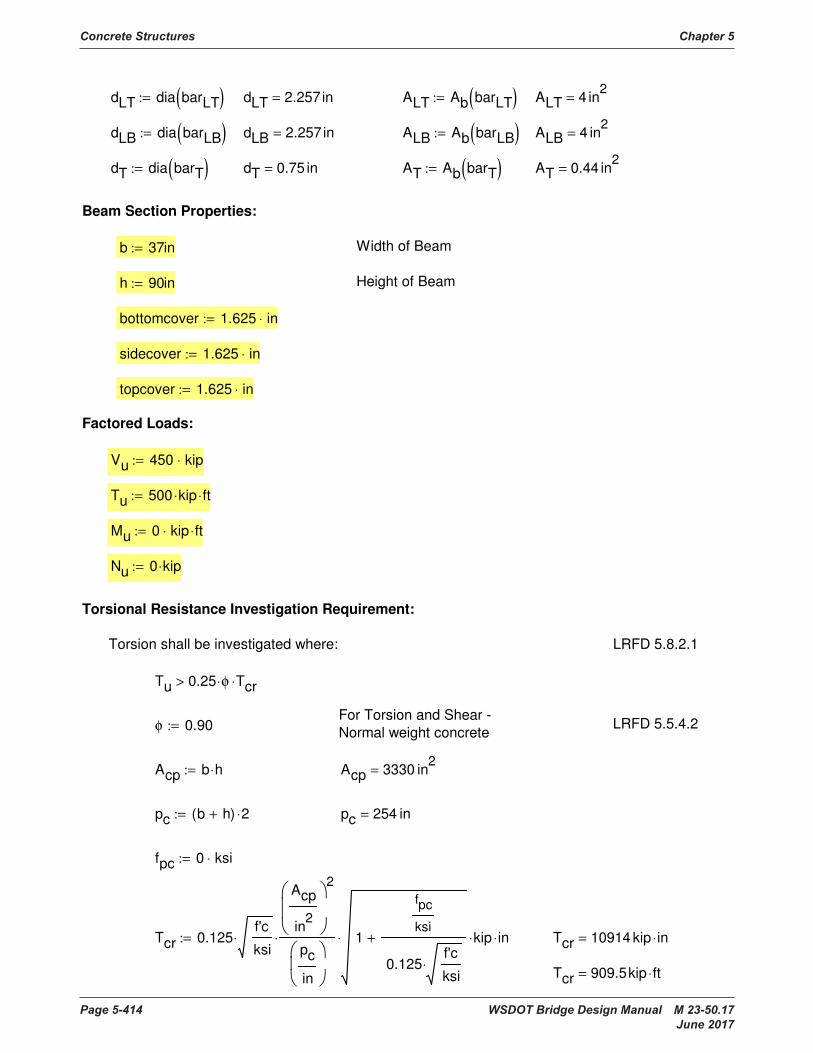
Concrete Structures Chapter 5
Page 5-414 WSDOT Bridge Design Manual M 23-50.17 June 2017
Factored Loads:
Vu 450 kip⋅:=
Tu 500 kip⋅ ft⋅:=
Mu 0 kip⋅ ft⋅:=
Nu 0 kip⋅:=
Torsional Resistance Investigation Requirement:
Torsion shall be investigated where: LRFD 5.8.2.1
Tu 0.25 φ⋅ Tcr⋅>
For Torsion and Shear - Normal weight concreteφ 0.90:= LRFD 5.5.4.2
Acp b h⋅:= Acp 3330 in2=
pc b h+( ) 2⋅:= pc 254 in=
fpc 0 ksi⋅:=
Tcr 0.125f'c
ksi⋅
Acp
in2
2
pc
in
⋅ 1
fpc
ksi
0.125f'c
ksi⋅
+⋅ kip⋅ in⋅:= Tcr 10914 kip in⋅=
Tcr 909.5kip ft⋅=
dLT dia barLT( ):= dLT 2.257in= ALT Ab barLT( ):= ALT 4 in2=
dLB dia barLB( ):= dLB 2.257in= ALB Ab barLB( ):= ALB 4 in2=
dT dia barT( ):= dT 0.75 in= AT Ab barT( ):= AT 0.44 in2=
Beam Section Properties:
b 37in:= Width of Beam
h 90in:= Height of Beam
bottomcover 1.625 in⋅:=
sidecover 1.625 in⋅:=
topcover 1.625 in⋅:=
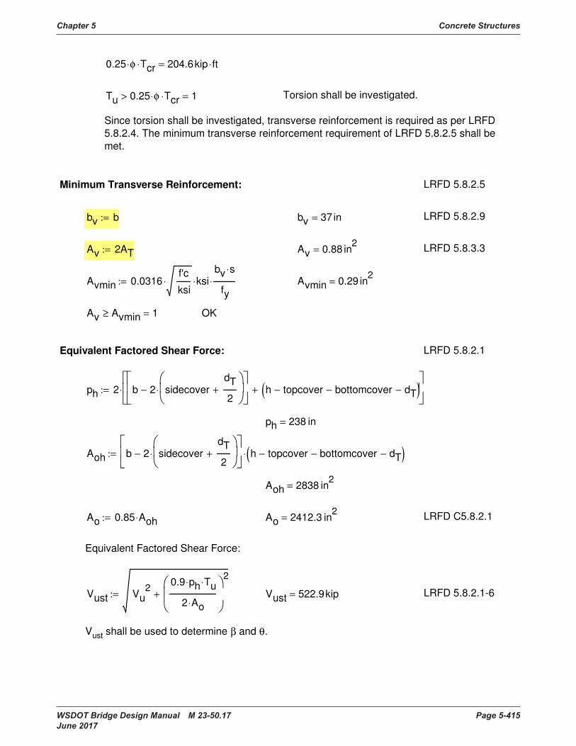
Chapter 5 Concrete Structures
WSDOT Bridge Design Manual M 23-50.17 Page 5-415 June 2017
Vust shall be used to determine β and θ.
LRFD 5.8.2.1-6Vust 522.9kip=Vust Vu2 0.9 ph⋅ Tu⋅
2 Ao⋅
2
+:=
Equivalent Factored Shear Force:
LRFD C5.8.2.1Ao 2412.3 in2=Ao 0.85 Aoh⋅:=
Aoh 2838 in2=
Aoh b 2 sidecoverdT
2+
⋅−
h topcover− bottomcover− dT−( )⋅:=
ph 238 in=
ph 2 b 2 sidecoverdT
2+
⋅−
h topcover− bottomcover− dT−( )+
⋅:=
LRFD 5.8.2.1Equivalent Factored Shear Force:
OKAv Avmin≥ 1=
Avmin 0.29 in2=Avmin 0.0316f'c
ksi⋅ ksi⋅
bv s⋅
fy⋅:=
LRFD 5.8.3.3Av 0.88 in2=Av 2AT:=
LRFD 5.8.2.9bv 37 in=bv b:=
LRFD 5.8.2.5Minimum Transverse Reinforcement:
Since torsion shall be investigated, transverse reinforcement is required as per LRFD 5.8.2.4. The minimum transverse reinforcement requirement of LRFD 5.8.2.5 shall be met.
Torsion shall be investigated.Tu 0.25 φ⋅ Tcr⋅> 1=
0.25 φ⋅ Tcr⋅ 204.6kip ft⋅=
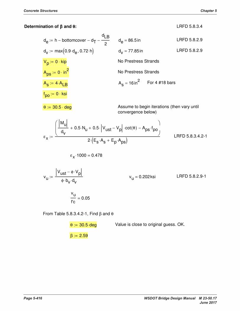
Concrete Structures Chapter 5
Page 5-416 WSDOT Bridge Design Manual M 23-50.17 June 2017
β 2.59:=
Value is close to original guess. OK.θ 30.5 deg⋅:=
From Table 5.8.3.4.2-1, Find β and θ
vu
f'c0.05=
LRFD 5.8.2.9-1vu 0.202ksi=vuVust φ Vp⋅−
φ bv⋅ dv⋅:=
εx 1000⋅ 0.478=
LRFD 5.8.3.4.2-1εx
Mu
dv0.5 Nu⋅+ 0.5 Vust Vp−⋅ cot θ( )⋅+ Aps fpo⋅−
2 Es As⋅ Ep Aps⋅+( )⋅:=
Assume to begin iterations (then vary until convergence below)
θ 30.5 deg⋅:=
fpo 0 ksi⋅:=
For 4 #18 barsAs 16 in2=As 4 ALB⋅:=
No Prestress StrandsAps 0 in2⋅:=
No Prestress StrandsVp 0 kip⋅:=
LRFD 5.8.2.9dv 77.85in=dv max 0.9 de⋅ 0.72 h⋅,( ):=
LRFD 5.8.2.9de 86.5 in=de h bottomcover− dT−dLB
2−:=
LRFD 5.8.3.4Determination of ββββ and θθθθ:

Chapter 5 Concrete Structures
WSDOT Bridge Design Manual M 23-50.17 Page 5-417 June 2017
Shear Resistance:
The factored Shear Resistance shall be:
Vr φ Vn⋅= LRFD 5.8.2.1
Vc 0.0316 β⋅f'c
ksi⋅ bv⋅ dv⋅ ksi⋅:= Vc 471.5kip= LRFD 5.8.3.3
α 90 deg⋅:=
VsAv fy⋅ dv⋅ cot θ( ) cot α( )+( )⋅ sin α( )⋅
s:= Vs 930.4kip= LRFD 5.8.3.3
Vn min Vc Vs+ Vp+ 0.25 f'c⋅ bv⋅ dv⋅ Vp+,( ):= Vn 1402 kip=
Vr φ Vn⋅:= Vr 1262 kip=
Vr Vu≥ 1= OK
Torsional Resistance:
The factored Torsional Resistance shall be: LRFD 5.8.2.1
Tr φ Tn⋅=
At AT:= At 0.44 in2= LRFD 5.8.3.6.2
Tn2 Ao⋅ At⋅ fy⋅ cot θ( )⋅
s:= Tn 28831 kip in⋅= LRFD 5.8.3.6.2-1
Tn 2403 kip ft⋅=
Tr φ Tn⋅:= Tr 25948 kip in⋅= LRFD 5.8.2.1
Tr 2162 kip ft⋅=
Tr Tu≥ 1= OK

Concrete Structures Chapter 5
Page 5-418 WSDOT Bridge Design Manual M 23-50.17 June 2017
if s smax≤ "OK", "NG",( ) "OK"=
smax 24 in=
smax if vu 0.125 f'c⋅< min 0.8 dv⋅ 24in,( ), min 0.4 dv⋅ 12in,( ),( ):=
0.125 f'c⋅ 0.5 ksi=
vu 0.202ksi=
LRFD 5.8.2.7Maximum Spacing of Transverse Reinforcement:
OKX1 X2≥ 1=
X2 258 kip=
X2Mu
φ dv⋅
0.5 Nu⋅
φ+ cot θ( )
Vu
φVp− 0.5 Vs⋅−
2 0.45 ph⋅ Tu⋅
2 Ao⋅ φ⋅
2
+⋅+:=
For a Solid Section:
X1 640 kip=X1 As fy⋅ Aps fps⋅+:=
fps 0 ksi⋅:=
LRFD 5.8.3.6.3Check for Longitudinal Reinforcement:

WSDOT Bridge Design Manual M 23-50.17 Page 5-419 June 2017
Appendix 5-B15 Sound Wall Design – Type D-2k
Std Spec. 8.15.2.1.1fr 474.3psi=fr 7.5f'c
psi⋅ psi⋅:=
β1 0.85=β1 if f'c 4000 psi⋅≤ 0.85, max 0.85
f'c 4000 psi⋅−
1000 psi⋅
0.05⋅− 0.65,
,
:=
Std Spec. 8.16.2.7
Std Spec. 8.7.1Ec 4.224 106
× psi=Ec
wc
pcf
1.5
33⋅f'c
psi⋅ psi⋅:=
f'c 4000 psi⋅:=
BDM 4.1.1wc 160 pcf⋅:=
Concrete Properties:
pcf lbf ft3−
⋅≡psf lbf ft2−
⋅≡plf lbf ft1−
⋅≡
klf kip ft1−
⋅≡kcf kip ft3−
⋅≡kip 1000 lbf⋅≡ksi 1000 psi⋅≡Define Units:
MathCAD file written by Brian Aldrich, July 15, 2004.
This design doesn't account for the loads of a combined retaining wall / noisewall. A maximum of 2
ft of retained fill above the final ground line is suggested.
This design is based upon:
AASHTO Guide Specifications for Structural Design of Sound Barriers - 1989 (including 2002 •
interim)
AASHTO Standard Specifications for Highway Bridges 17th Ed. - 2002•
USS Steel Sheet Piling Design Manual - July 1984•
WSDOT Bridge Design Manual•
Caltrans Trenching and Shoring Manual - June 1995•
Sound Wall Design - Type D-2k
Precast Panel on Shaft
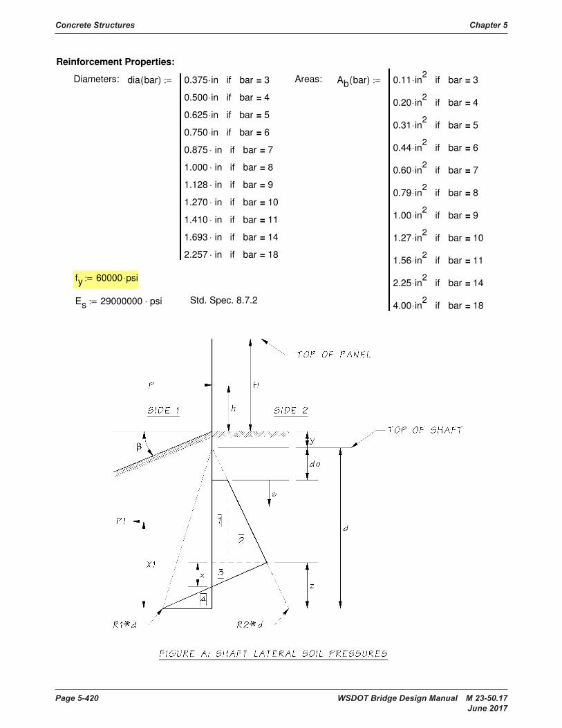
Concrete Structures Chapter 5
Page 5-420 WSDOT Bridge Design Manual M 23-50.17 June 2017
Reinforcement Properties:
Diameters: dia bar( ) 0.375 in⋅ bar 3=if
0.500 in⋅ bar 4=if
0.625 in⋅ bar 5=if
0.750 in⋅ bar 6=if
0.875 in⋅ bar 7=if
1.000 in⋅ bar 8=if
1.128 in⋅ bar 9=if
1.270 in⋅ bar 10=if
1.410 in⋅ bar 11=if
1.693 in⋅ bar 14=if
2.257 in⋅ bar 18=if
:= Areas: Ab bar( ) 0.11 in2
⋅ bar 3=if
0.20 in2
⋅ bar 4=if
0.31 in2
⋅ bar 5=if
0.44 in2
⋅ bar 6=if
0.60 in2
⋅ bar 7=if
0.79 in2
⋅ bar 8=if
1.00 in2
⋅ bar 9=if
1.27 in2
⋅ bar 10=if
1.56 in2
⋅ bar 11=if
2.25 in2
⋅ bar 14=if
4.00 in2
⋅ bar 18=if
:=
fy 60000 psi⋅:=
Es 29000000 psi⋅:= Std. Spec. 8.7.2
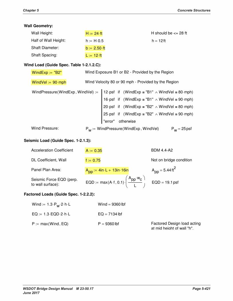
Chapter 5 Concrete Structures
WSDOT Bridge Design Manual M 23-50.17 Page 5-421 June 2017
Acceleration Coefficient A 0.35:= BDM 4.4-A2
DL Coefficient, Wall f 0.75:= Not on bridge condition
Panel Plan Area: App 4in L⋅ 13in 16⋅ in+:= App 5.44 ft2
=
Seismic Force EQD (perp.
to wall surface):EQD max A f⋅ 0.1,( )
App wc⋅
L
⋅:= EQD 19.1psf=
Factored Loads (Guide Spec. 1-2.2.2):
Wind 1.3 Pw⋅ 2⋅ h⋅ L⋅:= Wind 9360 lbf=
EQ 1.3 EQD⋅ 2⋅ h⋅ L⋅:= EQ 7134 lbf=
P max Wind EQ,( ):= P 9360 lbf= Factored Design load acting
at mid height of wall "h".
Wall Geometry:
Wall Height: H 24 ft⋅:= H should be <= 28 ft
Half of Wall Height: h H 0.5⋅:= h 12ft=
Shaft Diameter: b 2.50 ft⋅:=
Shaft Spacing: L 12 ft⋅:=
Wind Load (Guide Spec. Table 1-2.1.2.C):
WindExp "B2":= Wind Exposure B1 or B2 - Provided by the Region
WindVel 90 mph⋅:= Wind Velocity 80 or 90 mph - Provided by the Region
WindPressure WindExp WindVel,( ) 12 psf⋅ WindExp "B1"= WindVel 80 mph⋅=∧( )if
16 psf⋅ WindExp "B1"= WindVel 90 mph⋅=∧( )if
20 psf⋅ WindExp "B2"= WindVel 80 mph⋅=∧( )if
25 psf⋅ WindExp "B2"= WindVel 90 mph⋅=∧( )if
"error" otherwise
:=
Wind Pressure: Pw WindPressure WindExp WindVel,( ):= Pw 25psf=
Seismic Load (Guide Spec. 1-2.1.3):

Concrete Structures Chapter 5
Page 5-422 WSDOT Bridge Design Manual M 23-50.17 June 2017
Iso 3.00=
Factor of Safety: FS 1.00:=
Angle of Wall Friction: δ2
3φ⋅:= δ 25.333 deg= Guide Spec. App. C pg. 33
Correction Factor for
Horizontal Component of
Earth Pressure:
HC cos δ( ):= HC 0.904=
Foundation Strength
Reduction Factors:φ fa 1.00:= Active( ) Guide Spec. 1-2.2.3
φ fp 0.90:= Passive( ) Guide Spec. 1-2.2.3
at mid height of wall "h".
Soil Parameters:
Soil Friction Angle: φ 38 deg⋅:= Provided by the Region
Soil Unit Weight: γ 125 pcf⋅:= Provided by the Region
Top Soil Depth: y 2.0 ft⋅:= From top of shaft to ground line
Ineffective Shaft Depth: do 0.5 ft⋅:= Depth of neglected soil at shaft
Factor used to amplify the
passive resistance based on
soil wedge behavior resulting
from shaft spacing - Caltrans
pg 10-2.
Isolation Factor for Shafts: Iso min 3.0 0.08φ
deg⋅,
L
b,
:=
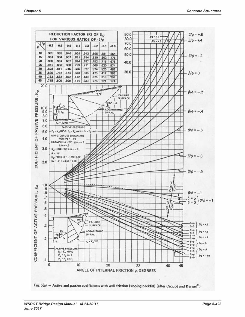
Chapter 5 Concrete Structures
WSDOT Bridge Design Manual M 23-50.17 Page 5-423 June 2017
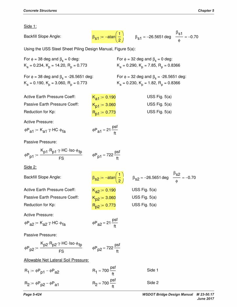
Concrete Structures Chapter 5
Page 5-424 WSDOT Bridge Design Manual M 23-50.17 June 2017
Backfill Slope Angle: βs2 atan1
2
−:= βs2 26.5651− deg=
βs2
φ
0.70−=
Active Earth Pressure Coeff: Ka2 0.190:= USS Fig. 5(a)
Passive Earth Pressure Coeff: Kp2 3.060:= USS Fig. 5(a)
Reduction for Kp: Rp2 0.773:= USS Fig. 5(a)
Active Pressure:
φPa2 Ka2 γ⋅ HC⋅ φ fa⋅:= φPa2 21psf
ft=
Passive Pressure:
φPp2
Kp2 Rp2⋅ γ⋅ HC⋅ Iso⋅ φ fp⋅
FS:= φPp2 722
psf
ft=
Allowable Net Lateral Soil Pressure:
R1 φPp1 φPa2−:= R1 700psf
ft= Side 1
R2 φPp2 φPa1−:= R2 700psf
ft= Side 2
Side 1:
Backfill Slope Angle: βs1 atan1
2
−:= βs1 26.5651− deg=
βs1
φ
0.70−=
Using the USS Steel Sheet Piling Design Manual, Figure 5(a):
For φ = 38 deg and βs = 0 deg:
Ka = 0.234, Kp = 14.20, Rp = 0.773
For φ = 32 deg and βs = 0 deg:
Ka = 0.290, Kp = 7.85, Rp = 0.8366
For φ = 38 deg and βs = -26.5651 deg:
Ka = 0.190, Kp = 3.060, Rp = 0.773
For φ = 32 deg and βs = -26.5651 deg:
Ka = 0.230, Kp = 1.82, Rp = 0.8366
Active Earth Pressure Coeff: Ka1 0.190:= USS Fig. 5(a)
Passive Earth Pressure Coeff: Kp1 3.060:= USS Fig. 5(a)
Reduction for Kp: Rp1 0.773:= USS Fig. 5(a)
Active Pressure:
φPa1 Ka1 γ⋅ HC⋅ φ fa⋅:= φPa1 21psf
ft=
Passive Pressure:
φPp1
Kp1 Rp1⋅ γ⋅ HC⋅ Iso⋅ φ fp⋅
FS:= φPp1 722
psf
ft=
Side 2:
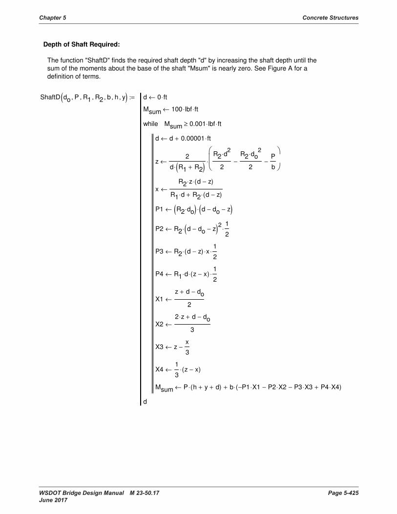
Chapter 5 Concrete Structures
WSDOT Bridge Design Manual M 23-50.17 Page 5-425 June 2017
Depth of Shaft Required:
The function "ShaftD" finds the required shaft depth "d" by increasing the shaft depth until the
sum of the moments about the base of the shaft "Msum" is nearly zero. See Figure A for a
definition of terms.
ShaftD do P, R1, R2, b, h, y,( ) d 0 ft⋅←
Msum 100 lbf⋅ ft⋅←
d d 0.00001 ft⋅+←
z2
d R1 R2+( )⋅
R2 d2
⋅
2
R2 do2
⋅
2−
P
b−
⋅←
xR2 z⋅ d z−( )⋅
R1 d⋅ R2 d z−( )⋅+
←
P1 R2 do⋅( ) d do− z−( )⋅←
P2 R2 d do− z−( )2
⋅1
2⋅←
P3 R2 d z−( )⋅ x⋅1
2⋅←
P4 R1 d⋅ z x−( )⋅1
2⋅←
X1z d+ do−
2←
X22 z⋅ d+ do−
3←
X3 zx
3−←
X41
3z x−( )⋅←
Msum P h y+ d+( )⋅ b P1− X1⋅ P2 X2⋅− P3 X3⋅− P4 X4⋅+( )⋅+←
Msum 0.001 lbf⋅ ft⋅≥while
d
:=
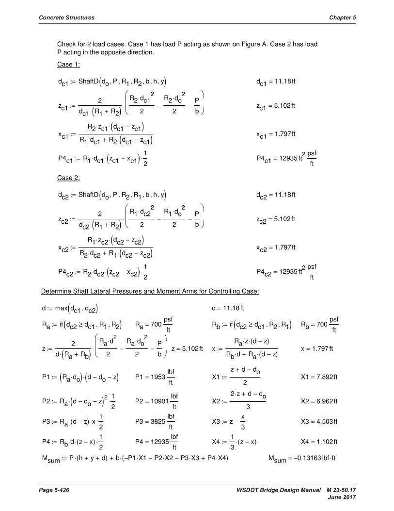
Concrete Structures Chapter 5
Page 5-426 WSDOT Bridge Design Manual M 23-50.17 June 2017
Rb if dc2 dc1≥ R2, R1,( ):= Rb 700psf
ft=
z2
d Ra Rb+( )⋅
Ra d2
⋅
2
Ra do2
⋅
2−
P
b−
⋅:= z 5.102ft= xRa z⋅ d z−( )⋅
Rb d⋅ Ra d z−( )⋅+
:= x 1.797ft=
P1 Ra do⋅( ) d do− z−( )⋅:= P1 1953lbf
ft= X1
z d+ do−
2:= X1 7.892ft=
P2 Ra d do− z−( )2
⋅1
2⋅:= P2 10901
lbf
ft= X2
2 z⋅ d+ do−
3:= X2 6.962ft=
P3 Ra d z−( )⋅ x⋅1
2⋅:= P3 3825
lbf
ft= X3 z
x
3−:= X3 4.503ft=
P4 Rb d⋅ z x−( )⋅1
2⋅:= P4 12935
lbf
ft= X4
1
3z x−( )⋅:= X4 1.102ft=
Msum P h y+ d+( )⋅ b P1− X1⋅ P2 X2⋅− P3 X3⋅− P4 X4⋅+( )⋅+:= Msum 0.13163− lbf ft⋅=
Check for 2 load cases. Case 1 has load P acting as shown on Figure A. Case 2 has load
P acting in the opposite direction.
Case 1:
dc1 ShaftD do P, R1, R2, b, h, y,( ):= dc1 11.18ft=
zc12
dc1 R1 R2+( )⋅
R2 dc12
⋅
2
R2 do2
⋅
2−
P
b−
⋅:= zc1 5.102ft=
xc1
R2 zc1⋅ dc1 zc1−( )⋅
R1 dc1⋅ R2 dc1 zc1−( )⋅+
:= xc1 1.797ft=
P4c1 R1 dc1⋅ zc1 xc1−( )⋅1
2⋅:= P4c1 12935 ft
2 psf
ft=
Case 2:
dc2 ShaftD do P, R2, R1, b, h, y,( ):= dc2 11.18ft=
zc22
dc2 R1 R2+( )⋅
R1 dc22
⋅
2
R1 do2
⋅
2−
P
b−
⋅:= zc2 5.102ft=
xc2
R1 zc2⋅ dc2 zc2−( )⋅
R2 dc2⋅ R1 dc2 zc2−( )⋅+
:= xc2 1.797ft=
P4c2 R2 dc2⋅ zc2 xc2−( )⋅1
2⋅:= P4c2 12935 ft
2 psf
ft=
Determine Shaft Lateral Pressures and Moment Arms for Controlling Case:
d max dc1 dc2,( ):= d 11.18 ft=
Ra if dc2 dc1≥ R1, R2,( ):= Ra 700psf
ft=

Chapter 5 Concrete Structures
WSDOT Bridge Design Manual M 23-50.17 Page 5-427 June 2017
Mshaftc2 P h y+ do+ sc2+( )⋅ R1 do⋅ b⋅ sc22
⋅1
2⋅− R1 b⋅ sc2
3⋅
1
6⋅−:= Mshaftc2 152094 lbf ft⋅=
Check that the point where shear = 0 occurs in areas 1 and 2 on Figure A:
Check2 if sc2 dc2 do− zc2−( )≤ "OK", "NG", := Check2 "OK"=
Mshaft max Mshaftc1 Mshaftc2,( ):= Mshaft 152094 lbf ft⋅=
Anchor Bolt and Panel Post Design Values:
Vbolt P:= Vbolt 9360 lbf=
Mbolt P h y+( )⋅:= Mbolt 131040 lbf ft⋅=
Panel Design Value (about a vertical axis):
Find Design Moment for a 1 ft wide strip of wall (between panel posts) for the panel flexure design
wpanel max Pw max A f⋅ 0.1,( ) 4in wc⋅( )⋅, := wpanel 25.0psf=
Shaft Design Values:
The Maximum Shear will occur at the bolts or at the top of area 4 on Figure A:
Vshaft max P P4c1 b⋅, P4c2 b⋅,( ):= Vshaft 32339 lbf=
The Maximum Moment in the shaft will occur where the shear = 0.
Assume that the point where shear = 0 occurs in areas 1 and 2 on Figure A.
Check for Case 1:
sc1 do− do2 2 P⋅
R2 b⋅++:= sc1 2.808ft=
Mshaftc1 P h y+ do+ sc1+( )⋅ R2 do⋅ b⋅ sc12
⋅1
2⋅− R2 b⋅ sc1
3⋅
1
6⋅−:= Mshaftc1 152094 lbf ft⋅=
Check that the point where shear = 0 occurs in areas 1 and 2 on Figure A:
Check1 if sc1 dc1 do− zc1−( )≤ "OK", "NG", := Check1 "OK"=
Check for Case 2:
sc2 do− do2 2 P⋅
R1 b⋅++:= sc2 2.808ft=
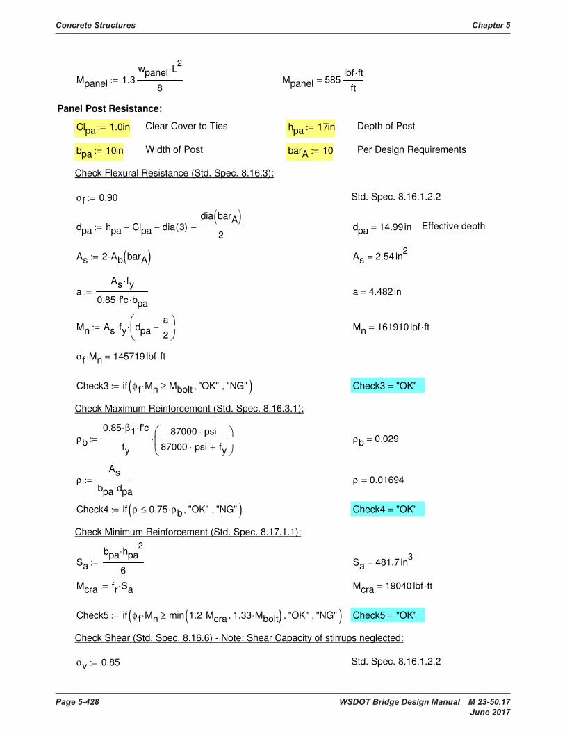
Concrete Structures Chapter 5
Page 5-428 WSDOT Bridge Design Manual M 23-50.17 June 2017
Mn 161910 lbf ft⋅=
φ f Mn⋅ 145719 lbf ft⋅=
Check3 if φ f Mn⋅ Mbolt≥ "OK", "NG",( ):= Check3 "OK"=
Check Maximum Reinforcement (Std. Spec. 8.16.3.1):
ρb
0.85 β1⋅ f'c⋅
fy
87000 psi⋅
87000 psi⋅ fy+
⋅:= ρb 0.029=
ρ
As
bpa dpa⋅
:= ρ 0.01694=
Check4 if ρ 0.75 ρb⋅≤ "OK", "NG",( ):= Check4 "OK"=
Check Minimum Reinforcement (Std. Spec. 8.17.1.1):
Sa
bpa hpa2
⋅
6:= Sa 481.7 in
3=
Mcra fr Sa⋅:= Mcra 19040 lbf ft⋅=
Check5 if φ f Mn⋅ min 1.2 Mcra⋅ 1.33 Mbolt⋅,( )≥ "OK", "NG",( ):= Check5 "OK"=
Check Shear (Std. Spec. 8.16.6) - Note: Shear Capacity of stirrups neglected:
φv 0.85:= Std. Spec. 8.16.1.2.2
Mpanel 1.3wpanel L
2⋅
8:= Mpanel 585
lbf ft⋅
ft=
Panel Post Resistance:
Clpa 1.0in:= Clear Cover to Ties hpa 17in:= Depth of Post
bpa 10in:= Width of Post barA 10:= Per Design Requirements
Check Flexural Resistance (Std. Spec. 8.16.3):
φ f 0.90:= Std. Spec. 8.16.1.2.2
dpa hpa Clpa− dia 3( )−
dia barA( )
2−:= dpa 14.99in= Effective depth
As 2 Ab barA( )⋅:= As 2.54 in2
=
aAs fy⋅
0.85 f'c⋅ bpa⋅
:= a 4.482 in=
Mn As fy⋅ dpaa
2−
⋅:=

Chapter 5 Concrete Structures
WSDOT Bridge Design Manual M 23-50.17 Page 5-429 June 2017
Mn 147892 lbf ft⋅=
φ f Mn⋅ 133103 lbf ft⋅=
Check7 if φ f Mn⋅ Mbolt≥ "OK", "NG",( ):= Check7 "OK"=
Check Maximum Reinforcement (Std. Spec. 8.16.3.1):
ρb
0.85 β1⋅ f'c⋅
fy
87000 psi⋅
87000 psi⋅ fy+
⋅:= ρb 0.029=
ρ
As
bpb dpb⋅
:= ρ 0.01327=
Check8 if ρ 0.75 ρb⋅≤ "OK", "NG",( ):= Check8 "OK"=
Check Minimum Reinforcement (Std. Spec. 8.17.1.1):
Sb
bpb hpb2
⋅
6:= Sb 459.4 in
3=
Mcrb fr Sb⋅:= Mcrb 18158 lbf ft⋅=
Check9 if φ f Mn⋅ min 1.2 Mcrb⋅ 1.33 Mbolt⋅,( )≥ "OK", "NG",( ):= Check9 "OK"=
Check Shear (Std. Spec. 8.16.6) - Note: Shear Capacity of stirrups neglected:
φv 0.85= Std. Spec. 8.16.1.2.2
Vca 2f'c
psi⋅ psi⋅ bpa⋅ dpa⋅:= Vca 18961 lbf=
Check6 if φv Vca⋅ Vbolt≥ "OK", "NG",( ):= Check6 "OK"=
Panel Post Base Resistance:
bpb 9in:= Width of Panel Post Base barB 9:= Per Design Requirements
hpb 17.5in:= Depth of Panel Post Base
Check Flexural Resistance (Std. Spec. 8.16.3):
φ f 0.9= Std. Spec. 8.16.1.2.2
dpb hpb 0.75in−:= dpb 16.75in= Effective depth
As 2 Ab barB( )⋅:= As 2 in2
=
aAs fy⋅
0.85 f'c⋅ bpb⋅
:= a 3.922 in=
Mn As fy⋅ dpba
2−
⋅:=

Concrete Structures Chapter 5
Page 5-430 WSDOT Bridge Design Manual M 23-50.17 June 2017
Check11 "OK"=Check11 if barA 11≤ barB 11≤∧ "OK", "NG",( ):=
Note: Lap Splices are not allowed for bar sizes greater than 11 per AASHTO Std. Spec. 8.32.1.1.
LapSplice 9.558ft=LapSplice max 1.7 ldA⋅ ldB, 2 ft⋅,( ):=
The required lapsplice Y is the maximum of the required lap splice length of bar A (using a
Class C splice), the development length of bar B, or 2'-0" per BDM 5.1.2.D.
Required Lapsplice (Y):
ldB 4.427ft=ldB lbasicB 1.4⋅:=
ldA 5.623ft=ldA lbasicA 1.4⋅:=
For top reinforcement placed with more than 12 inches of concrete cast below (Std. Spec.
8.25.2.1):
Development Length (Std. Spec. 8.25):
lbasicB 3.162ft=lbasicB lbasic barB( ):=
lbasicA 4.016ft=lbasicA lbasic barA( ):=
lbasic bar( ) max0.04 Ab bar( )⋅ fy⋅
f'c
psipsi⋅ in⋅
0.0004 dia bar( )⋅
fy
psi⋅,
bar 11≤if
0.085 fy⋅
f'c
psipsi⋅
in⋅ bar 14=if
0.11 fy⋅
f'c
psipsi⋅
in⋅ bar 18=if
"error" otherwise
:=
Basic Development Length (Std. Spec. 8.25.1):
Required Splice Length (Std. Spec. 8.25 and 8.32):
Check10 "OK"=Check10 if φv Vcb⋅ Vbolt≥ "OK", "NG",( ):=
Vcb 19069 lbf=Vcb 2f'c
psi⋅ psi⋅ bpb⋅ dpb⋅:=
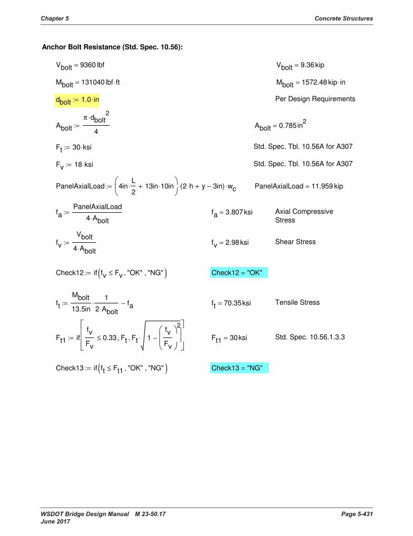
Chapter 5 Concrete Structures
WSDOT Bridge Design Manual M 23-50.17 Page 5-431 June 2017
Check13 "NG"=Check13 if ft Ft1≤ "OK", "NG",( ):=
Std. Spec. 10.56.1.3.3Ft1 30ksi=Ft1 iffv
Fv
0.33≤ Ft, Ft 1fv
Fv
2
−⋅,
:=
Tensile Stressft 70.35ksi=ft
Mbolt
13.5in
1
2 Abolt⋅
⋅ fa−:=
Check12 "OK"=Check12 if fv Fv≤ "OK", "NG",( ):=
Shear Stressfv 2.98ksi=fv
Vbolt
4 Abolt⋅
:=
Axial Compressive
Stressfa 3.807ksi=fa
PanelAxialLoad
4 Abolt⋅
:=
PanelAxialLoad 11.959 kip=PanelAxialLoad 4inL
2⋅ 13in 10⋅ in+
2 h⋅ y+ 3in−( )⋅ wc⋅:=
Std. Spec. Tbl. 10.56A for A307Fv 18 ksi⋅:=
Std. Spec. Tbl. 10.56A for A307Ft 30 ksi⋅:=
Abolt 0.785in2
=Abolt
π dbolt2
⋅
4:=
Per Design Requirementsdbolt 1.0 in⋅:=
Mbolt 1572.48 kip in⋅=Mbolt 131040 lbf ft⋅=
Vbolt 9.36kip=Vbolt 9360 lbf=
Anchor Bolt Resistance (Std. Spec. 10.56):
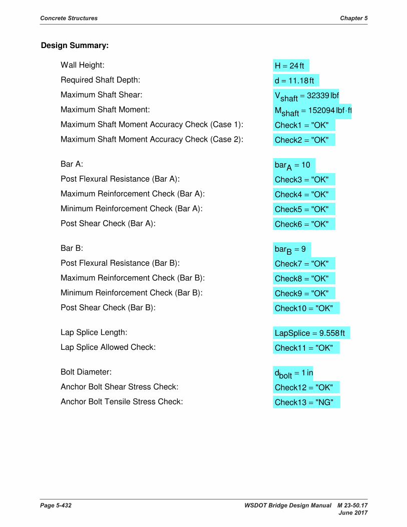
Concrete Structures Chapter 5
Page 5-432 WSDOT Bridge Design Manual M 23-50.17 June 2017
Check6 "OK"=
Bar B: barB 9=
Post Flexural Resistance (Bar B): Check7 "OK"=
Maximum Reinforcement Check (Bar B): Check8 "OK"=
Minimum Reinforcement Check (Bar B): Check9 "OK"=
Post Shear Check (Bar B): Check10 "OK"=
Lap Splice Length: LapSplice 9.558ft=
Lap Splice Allowed Check: Check11 "OK"=
Bolt Diameter: dbolt 1 in=
Anchor Bolt Shear Stress Check: Check12 "OK"=
Anchor Bolt Tensile Stress Check: Check13 "NG"=
Design Summary:
Wall Height: H 24ft=
Required Shaft Depth: d 11.18 ft=
Maximum Shaft Shear: Vshaft 32339 lbf=
Maximum Shaft Moment: Mshaft 152094 lbf ft⋅=
Maximum Shaft Moment Accuracy Check (Case 1): Check1 "OK"=
Maximum Shaft Moment Accuracy Check (Case 2): Check2 "OK"=
Bar A: barA 10=
Post Flexural Resistance (Bar A): Check3 "OK"=
Maximum Reinforcement Check (Bar A): Check4 "OK"=
Minimum Reinforcement Check (Bar A): Check5 "OK"=
Post Shear Check (Bar A):
Chapter 5 Concrete Structures
WSDOT Bridge Design Manual M 23-50.17 Page 5-433 June 2017
5.99 References1. AASHTO LRFD Bridge Construction Specifications, Current Edition, AASHTO,
Washington, D.C.
2. Seguirant, S.J., “New Deep WSDOT Standard Sections Extend Spans of Prestressed Concrete Girders,” PCI JOURNAL, V. 43, No. 4, July-August 1998, pp. 92-119.
3. PCI Bridge Design Manual, Precast/Prestressed Concrete Institute, Chicago, IL, 1997.
4. ACI 318-02, Building Code Requirements for Reinforced Concrete and Commentary, American Concrete Institute, 1989, pp.353.
5. Hsu, T. T. C., Torsion of Reinforced Concrete, Van Nostrand Reinhold Co., New York, 1st Ed., 1984, 516 pp.
6. Collins, M. P. and Mitchell, D., Shear and Torsion Design of Prestressed and Non-PrestressedConcreteBeams,PCIJournal,September-October,1980,pp.32-100.
7. Mirza, S.A., and Furlong, R.W., Design of Reinforced and Prestressed Concrete Inverted T Beams for Bridge Structures, PCI Journal, Vol. 30, No. 4, July-August 1985, pp. 112-136.
8. Rabbat,B.G.,ReaderCommentsDesignofReinforcedandPrestressedConcreteinverted T Beams for Bridge Structures, PCI Journal, Vol. 31, No. 3, May-June 1986, pp. 157-163.
9. ACI Committee 345, Guide for Widening Highway Bridges, ACI Structural Journal, July/August, 1992, pp. 451-466.
10.PCIDesignHandbook,PrecastandPrestressedConcrete,SixthEdition, Precast/Prestressed Concrete Institute, Chicago, IL, 2004.
11.Mast,R.F.,“LateralStabilityofLongPrestressedConcreteBeams,Part1,”PCIJOURNAL,V.34,No.1,January-February1989,pp.34-53.
12.Mast,R.F.,“LateralStabilityofLongPrestressedConcreteBeams,Part2,”PCIJOURNAL,V.38,No.1,January-February1993,pp.70-88.
13. Imper, R.R., and Laszlo, G., “Handling and Shipping of Long Span Bridge Beams,”PCIJOURNAL,V.32,No.6,November-December1987,pp.86-101.
14. Manual for the Evaluation and Repair of Precast, Prestressed Concrete Bridge Products, Precast/Prestressed Concrete Institute, Chicago, IL, 2006.
15. Transportation Research Board Report No. 226 titled, Damage Evaluation and RepairMethodsforPrestressedConcreteBridgeMembers.
16. Transportation Research Board Report No. 280 titled, Guidelines for Evaluation andRepairofPrestressedConcreteBridgeMembers.
17. Post-tensioned Box Girder Bridge Manual, Post-tensioning Institute, 301WestOsborn,Phoenix,Arizona.
18. Prestressed Concrete Structures T. Y. Lin, Wiley.
19. Prestressed Concrete Vol. I and II, Guyon, Wiley
Concrete Structures Chapter 5
Page 5-434 WSDOT Bridge Design Manual M 23-50.17 June 2017
20. Design of Concrete Bridges for Temperature Gradients, ACI Journal, May 1978.
21.Mast,R.F.,“UnifiedDesignProvisionsforReinforcedandPrestressedConcreteFlexuralandCompressionMembers”,ACIStructuralJournal,V.89,No.2,March-April1992,pp.185-199.SeealsodiscussionsbyR.K.DevalapuraandM.K.Tadros, C.W. Dolan and J.V. Loscheider and closure to discussions in V. 89, No. 5, September-October1992,pp.591-593.
22. Weigel, J.A., Seguirant, S.J., Brice, R., and Khaleghi, B., “High Performance Precast, Prestressed Concrete Girder Bridges in Washington State,” PCI JOURNAL, V. 48, No. 2, March-April 2003, pp. 28-52.
23. Seguirant, S. J., Brice, R., and Khaleghi, B., “Flexural Strength of Reinforced and Prestressed Concrete T-Beams,” PCI JOURNAL, V. 50, No. 1, January-February2005,pp44-73.
24.TRACReportWA-RD696.1,"EffectofIntermediateDiaphragmstoPrestressedConcrete Bridge Girders in Over-Height Truck Impacts” completed on April 2008 bytheWashingtonStateUniversity.
25. NCHRP Report 628, “Self-Consolidating Concrete for Precast, Prestressed Concrete Bridge Elements”, NCHRP Project 18-12, Transportation Research Board, 2009.
26.PCIPublicationCB-02-16-E,“RecommendedPracticeforLateralStabilityofPrecast, Prestressed Concrete Bridge Girders”, First Edition, Precast/Prestressed ConcreteInstitute,February2016.