WS8.1-1 ANSYS, Inc. Proprietary © 2009 ANSYS, Inc. All rights reserved. April 28, 2009 Inventory...
16
WS8.1-1 ANSYS, Inc. Proprietary © 2009 ANSYS, Inc. All rights reserved. April 28, 2009 Inventory #002597 Workshop 8.1 Line and Surface Bodies DesignModeler
-
Upload
kathleen-shields -
Category
Documents
-
view
221 -
download
0
Transcript of WS8.1-1 ANSYS, Inc. Proprietary © 2009 ANSYS, Inc. All rights reserved. April 28, 2009 Inventory...
WS8.1-1ANSYS, Inc. Proprietary© 2009 ANSYS, Inc. All rights reserved.
April 28, 2009Inventory #002597
Workshop 8.1
Line and Surface Bodies
DesignModeler

WS8.1-2ANSYS, Inc. Proprietary© 2009 ANSYS, Inc. All rights reserved.
April 28, 2009Inventory #002597
Workshop Supplement
Workshop 8.1, Line and Surface Bodies
•Goals:– Create a sketch representing beams used to stiffen a
panel.– Create a line body from the sketch. – Choose a beam cross section to be used and assign it
to the line body.– Create a surface model representing the panel.

WS8.1-3ANSYS, Inc. Proprietary© 2009 ANSYS, Inc. All rights reserved.
April 28, 2009Inventory #002597
Workshop Supplement
Workshop 8.1, Line and Surface Bodies
• Project Page>Component Systems>Geometry

WS8.1-4ANSYS, Inc. Proprietary© 2009 ANSYS, Inc. All rights reserved.
April 28, 2009Inventory #002597
Workshop Supplement
Workshop 8.1, Line and Surface Bodies
• Project Page>Component Systems>Geometry
a
b RMB
• DM will Open. When prompted choose “mm” as the length unit

WS8.1-5ANSYS, Inc. Proprietary© 2009 ANSYS, Inc. All rights reserved.
April 28, 2009Inventory #002597
Workshop Supplement
Create a rectangle in the XY Plane[Sketch] > Rectangle
1. Place the cursor near the origin until ‘P’ appears, click then drag to define the rectangle
Click “>Look At” & “>Zoom to Fit” tool buttons, and Triad ISO Ball as desired.
Workshop 8.1, Line and Surface Bodies
1

WS8.1-6ANSYS, Inc. Proprietary© 2009 ANSYS, Inc. All rights reserved.
April 28, 2009Inventory #002597
Workshop Supplement
Dimension the rectangle 600X300 mm as shown
[Sketch] > Dimension > General
Horizontal = 600 mm
Vertical = 300 mm
Fit the sketch and move dimensions as necessary
[Sketch] > Dimension > Move
Workshop 8.1, Line and Surface Bodies
WS8.1-7ANSYS, Inc. Proprietary© 2009 ANSYS, Inc. All rights reserved.
April 28, 2009Inventory #002597
Workshop Supplement
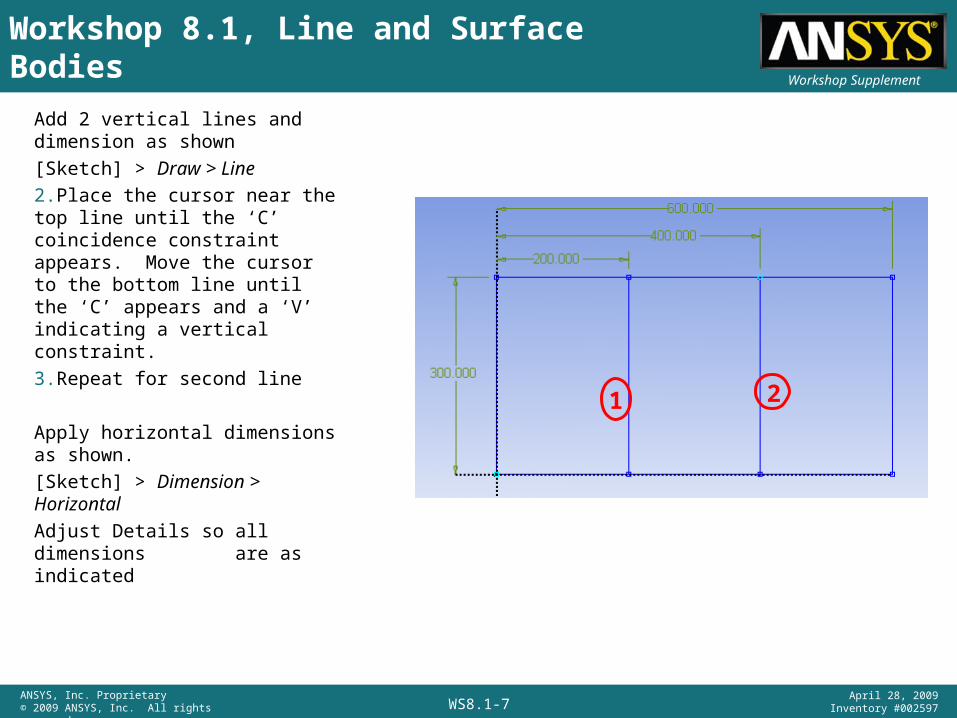
Add 2 vertical lines and dimension as shown
[Sketch] > Draw > Line
2.Place the cursor near the top line until the ‘C’ coincidence constraint appears. Move the cursor to the bottom line until the ‘C’ appears and a ‘V’ indicating a vertical constraint.
3.Repeat for second line
Apply horizontal dimensions as shown.
[Sketch] > Dimension > Horizontal
Adjust Details so all dimensions are as indicated
Workshop 8.1, Line and Surface Bodies
1 2
WS8.1-8ANSYS, Inc. Proprietary© 2009 ANSYS, Inc. All rights reserved.
April 28, 2009Inventory #002597
Workshop Supplement
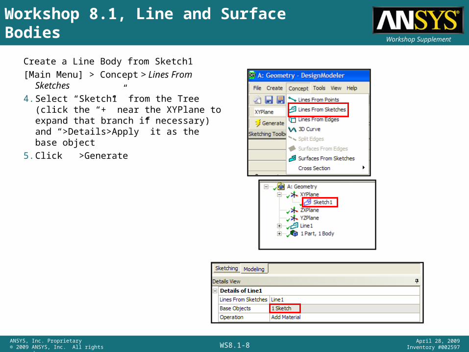
Create a Line Body from Sketch1
[Main Menu] > Concept > Lines From Sketches
4. Select “Sketch1” from the Tree (click the “+” near the XYPlane to expand that branch if necessary) and “>Details>Apply” it as the base object
5. Click >Generate
Workshop 8.1, Line and Surface Bodies

WS8.1-9ANSYS, Inc. Proprietary© 2009 ANSYS, Inc. All rights reserved.
April 28, 2009Inventory #002597
Workshop Supplement
Select a rectangular tube type cross section: [Main Menu] > Concept > Cross Section > Rectangular Tube
After selection, the cross section is displayed with its dimensions.
In this case we will use the default dimensions.
If desired the cross section Details can be changed to modify the cross section.
Workshop 8.1, Line and Surface Bodies
WS8.1-10ANSYS, Inc. Proprietary© 2009 ANSYS, Inc. All rights reserved.
April 28, 2009Inventory #002597
Workshop Supplement
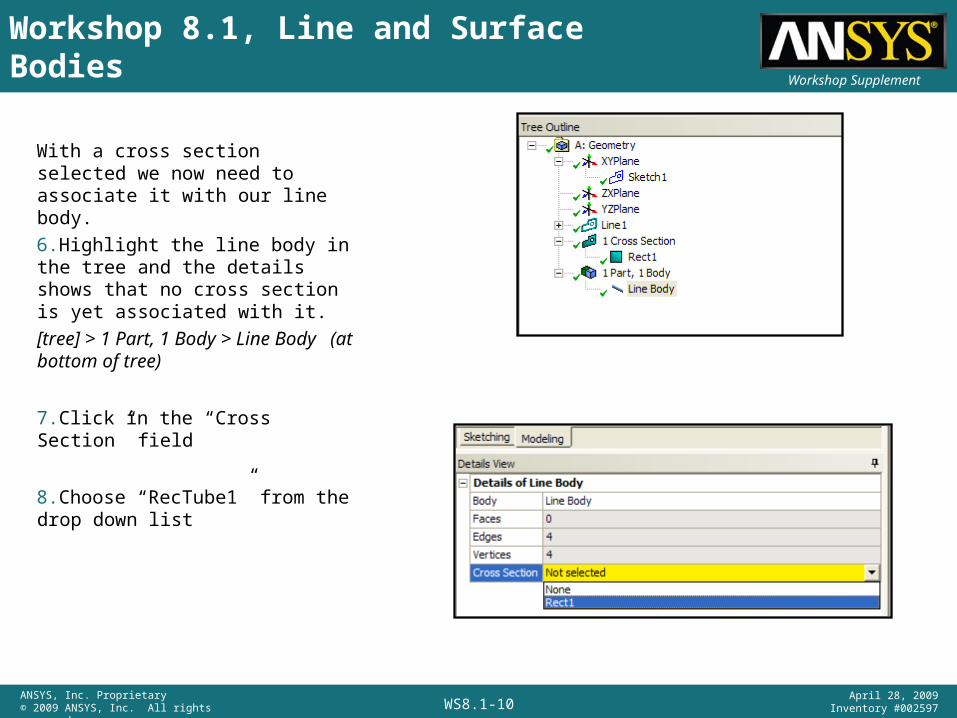
With a cross section selected we now need to associate it with our line body.
6.Highlight the line body in the tree and the details shows that no cross section is yet associated with it.
[tree] > 1 Part, 1 Body > Line Body (at bottom of tree)
7.Click in the “Cross Section” field
8.Choose “RecTube1” from the drop down list
Workshop 8.1, Line and Surface Bodies
WS8.1-11ANSYS, Inc. Proprietary© 2009 ANSYS, Inc. All rights reserved.
April 28, 2009Inventory #002597
Workshop Supplement
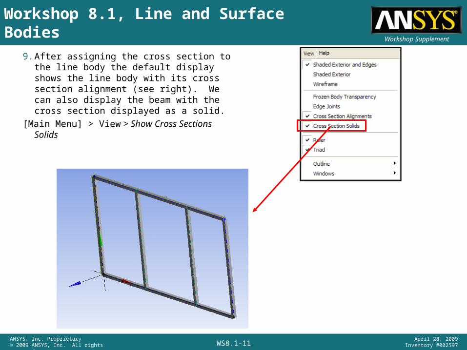
9. After assigning the cross section to the line body the default display shows the line body with its cross section alignment (see right). We can also display the beam with the cross section displayed as a solid.
[Main Menu] > View > Show Cross Sections Solids
Workshop 8.1, Line and Surface Bodies
WS8.1-12ANSYS, Inc. Proprietary© 2009 ANSYS, Inc. All rights reserved.
April 28, 2009Inventory #002597
Workshop Supplement
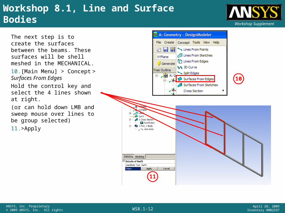
The next step is to create the surfaces between the beams. These surfaces will be shell meshed in the MECHANICAL.
10.[Main Menu] > Concept > Surfaces From Edges
Hold the control key and select the 4 lines shown at right.
(or can hold down LMB and sweep mouse over lines to be group selected)
11.>Apply
11
10
Workshop 8.1, Line and Surface Bodies
WS8.1-13ANSYS, Inc. Proprietary© 2009 ANSYS, Inc. All rights reserved.
April 28, 2009Inventory #002597
Workshop Supplement
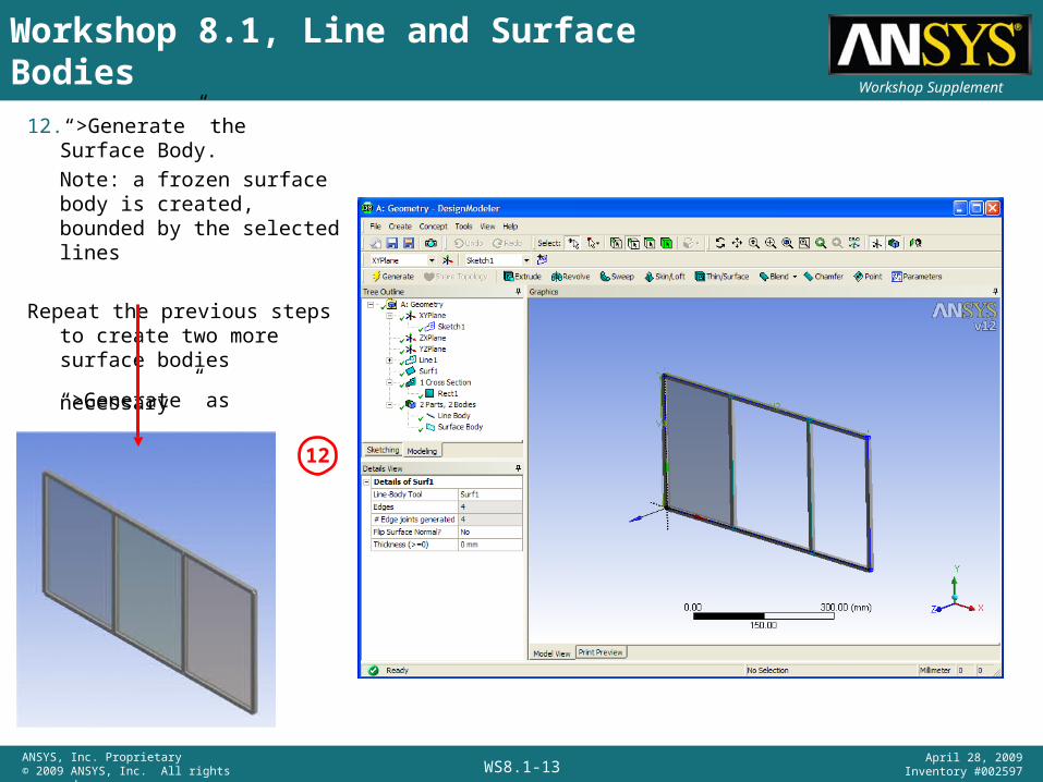
12. “>Generate” the Surface Body.
Note: a frozen surface body is created, bounded by the selected lines
Repeat the previous steps to create two more surface bodies
“>Generate” as necessary
12
Workshop 8.1, Line and Surface Bodies
WS8.1-14ANSYS, Inc. Proprietary© 2009 ANSYS, Inc. All rights reserved.
April 28, 2009Inventory #002597
Workshop Supplement
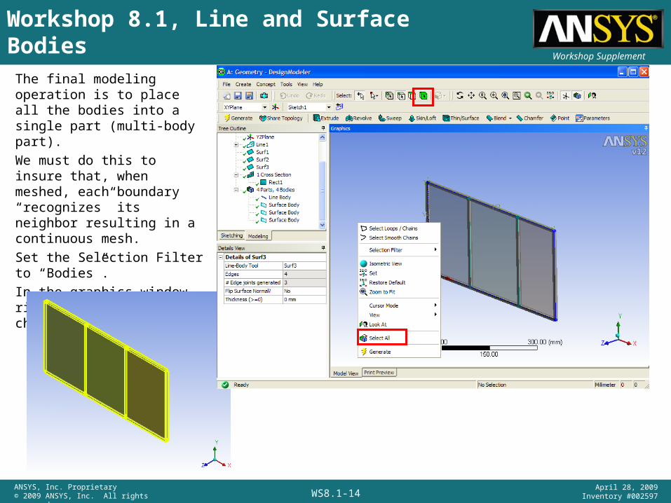
The final modeling operation is to place all the bodies into a single part (multi-body part).
We must do this to insure that, when meshed, each boundary “recognizes” its neighbor resulting in a continuous mesh.
Set the Selection Filter to “Bodies”.
In the graphics window right mouse click and choose “>Select All”
Workshop 8.1, Line and Surface Bodies
WS8.1-15ANSYS, Inc. Proprietary© 2009 ANSYS, Inc. All rights reserved.
April 28, 2009Inventory #002597
Workshop Supplement
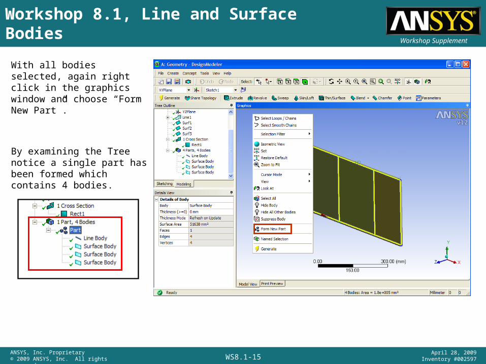
With all bodies selected, again right click in the graphics window and choose “Form New Part”.
By examining the Tree notice a single part has been formed which contains 4 bodies.
Workshop 8.1, Line and Surface Bodies
WS8.1-16ANSYS, Inc. Proprietary© 2009 ANSYS, Inc. All rights reserved.
April 28, 2009Inventory #002597
Workshop Supplement
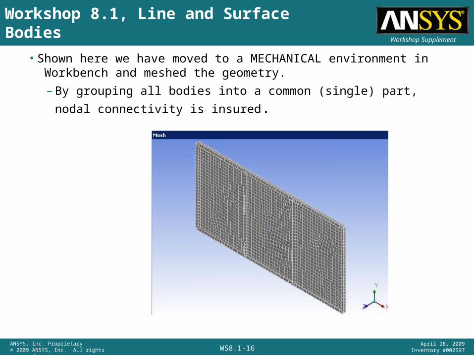
• Shown here we have moved to a MECHANICAL environment in Workbench and meshed the geometry.
– By grouping all bodies into a common (single) part, nodal connectivity
is insured.
Workshop 8.1, Line and Surface Bodies