Wrap-Up CSC 333. – 2 – Overview Wrap-Up of PIPE Design Performance analysis Fetch stage design...
29
Wrap-Up Wrap-Up CSC 333 CSC 333
-
date post
21-Dec-2015 -
Category
Documents
-
view
214 -
download
0
Transcript of Wrap-Up CSC 333. – 2 – Overview Wrap-Up of PIPE Design Performance analysis Fetch stage design...

Wrap-UpWrap-Up
CSC 333CSC 333CSC 333CSC 333

– 2 –
OverviewOverview
Wrap-Up of PIPE DesignWrap-Up of PIPE Design Performance analysis Fetch stage design Exceptional conditions
Modern High-Performance ProcessorsModern High-Performance Processors Out-of-order execution

– 3 –
Performance MetricsPerformance Metrics
Clock rateClock rate Measured in Megahertz or Gigahertz Function of stage partitioning and circuit design
Keep amount of work per stage small
Rate at which instructions executedRate at which instructions executed CPI: cycles per instruction On average, how many clock cycles does each instruction
require? Function of pipeline design and benchmark programs
E.g., how frequently are branches mispredicted?

– 4 –
CPI for PIPECPI for PIPE
CPI CPI 1.0 1.0 Fetch instruction each clock cycle Effectively process new instruction almost every cycle
Although each individual instruction has latency of 5 cycles
CPI CPI >> 1.0 1.0 Sometimes must stall or cancel branches
Computing CPIComputing CPI C clock cycles I instructions executed to completion B bubbles injected (C = I + B)
CPI = C/I = (I+B)/I = 1.0 + B/I Factor B/I represents average penalty due to bubbles

– 5 –
CPI for PIPE (Cont.)CPI for PIPE (Cont.)B/I = LP + MP + RP
LP: Penalty due to load/use hazard stalling Fraction of instructions that are loads 0.25 Fraction of load instructions requiring stall 0.20 Number of bubbles injected each time 1
LP = 0.25 * 0.20 * 1 = 0.05
MP: Penalty due to mispredicted branches Fraction of instructions that are cond. jumps 0.20 Fraction of cond. jumps mispredicted 0.40 Number of bubbles injected each time 2
MP = 0.20 * 0.40 * 2 = 0.16
RP: Penalty due to ret instructions Fraction of instructions that are returns 0.02 Number of bubbles injected each time 3
RP = 0.02 * 3 = 0.06
Net effect of penalties 0.05 + 0.16 + 0.06 = 0.27 CPI = 1.27 (Not bad!)
Typical Values

– 6 –
Fetch Logic RevisitedFetch Logic Revisited
During Fetch CycleDuring Fetch Cycle1. Select PC
2. Read bytes from instruction memory
3. Examine icode to determine instruction length
4. Increment PC
TimingTiming Steps 2 & 4 require
significant amount of time F
D rB
M_icode
PredictPC
valC valPicode ifun rA
Instructionmemory
Instructionmemory
PCincrement
PCincrement
predPC
Needregids
NeedvalC
Instrvalid
AlignAlignSplitSplit
Bytes 1-5Byte 0
SelectPC
M_Bch
M_valA
W_icode
W_valM

– 7 –
Standard Fetch TimingStandard Fetch Timing
Must Perform Everything in Sequence Can’t compute incremented PC until know how much to
increment it by
Select PC
Mem. Read Increment
need_regids, need_valC
1 clock cycle

– 8 –
A Fast PC Increment Circuit A Fast PC Increment Circuit
3-bit adder
need_ValC
need_regids
0
29-bitincre-
menter
MUX
High-order 29 bits
Low-order 3 bits
High-order 29 bits Low-order 3 bits
0 1
PC
incrPC
Slow Fast
carry

– 9 –
Modified Fetch TimingModified Fetch Timing
29-Bit Incrementer29-Bit Incrementer Acts as soon as PC selected Output not needed until final MUX Works in parallel with memory read
Select PC
Mem. Read
Incrementer
need_regids, need_valC3-bit add
MUX
1 clock cycle
Standard cycle

– 10 –
More Realistic Fetch LogicMore Realistic Fetch Logic
Fetch BoxFetch Box Integrated into instruction cache Fetches entire cache block (16 or 32 bytes) Selects current instruction from current block Works ahead to fetch next block
As reaches end of current blockAt branch target
InstructionCache
InstructionCache
Bytes 1-5Byte 0
Current Block
Next Block
CurrentInstructionCurrent
InstructionInstr.
LengthInstr.
LengthFetch
ControlFetch
Control
Other PC Controls

– 11 –
ExceptionsExceptions Conditions under which pipeline cannot continue normal
operation
CausesCauses Halt instruction (Current) Bad address for instruction or data (Previous) Invalid instruction (Previous) Pipeline control error (Previous)
Desired ActionDesired Action Complete some instructions
Either current or previous (depends on exception type)
Discard others Call exception handler
Like an unexpected procedure call

– 12 –
Exception ExamplesException Examples
Detect in Fetch StageDetect in Fetch Stage
irmovl $100,%eax rmmovl %eax,0x10000(%eax) # invalid address
jmp $-1 # Invalid jump target
.byte 0xFF # Invalid instruction code
halt # Halt instruction
Detect in Memory StageDetect in Memory Stage
– 13 –
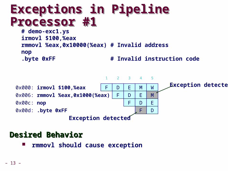
Exceptions in Pipeline Processor #1Exceptions in Pipeline Processor #1
Desired BehaviorDesired Behavior rmmovl should cause exception
# demo-exc1.ys irmovl $100,%eax rmmovl %eax,0x10000(%eax) # Invalid address nop .byte 0xFF # Invalid instruction code
0x000: irmovl $100,%eax
1 2 3 4
F D E M
F D E0x006: rmmovl %eax,0x1000(%eax)
0x00c: nop
0x00d: .byte 0xFF
F D
F
W
5
M
E
D
Exception detected
Exception detected

– 14 –
Exceptions in Pipeline Processor #2Exceptions in Pipeline Processor #2
Desired BehaviorDesired Behavior No exception should occur
# demo-exc2.ys 0x000: xorl %eax,%eax # Set condition codes 0x002: jne t # Not taken 0x007: irmovl $1,%eax 0x00d: irmovl $2,%edx 0x013: halt 0x014: t: .byte 0xFF # Target
0x000: xorl %eax,%eax
1 2 3
F D E
F D0x002: jne t
0x014: t: .byte 0xFF
0x???: (I’m lost!)
F
Exception detected
0x007: irmovl $1,%eax
4
M
E
F
D
W
5
M
D
F
E
E
D
M
6
M
E
W
7
W
M
8
W
9

– 15 –
Maintaining Exception OrderingMaintaining Exception Ordering
Add exception status field to pipeline registers Fetch stage sets to either “AOK,” “ADR” (when bad fetch
address), or “INS” (illegal instruction) Decode & execute pass values through Memory either passes through or sets to “ADR” Exception triggered only when instruction hits write back
F predPC
W icode valE valM dstE dstMexc
M Bchicode valE valA dstE dstMexc
E icode ifun valC valA valB dstE dstM srcA srcBexc
D rB valC valPicode ifun rAexc

– 16 –
Side Effects in Pipeline ProcessorSide Effects in Pipeline Processor
Desired BehaviorDesired Behavior rmmovl should cause exception No following instruction should have any effect
# demo-exc3.ys irmovl $100,%eax rmmovl %eax,0x10000(%eax) # invalid address addl %eax,%eax # Sets condition codes
0x000: irmovl $100,%eax
1 2 3 4
F D E M
F D E0x006: rmmovl %eax,0x1000(%eax)
0x00c: addl %eax,%eax F D
W
5
M
E
Exception detected
Condition code set

– 17 –
Avoiding Side EffectsAvoiding Side Effects
Presence of Exception Should Disable State UpdatePresence of Exception Should Disable State Update When detect exception in memory stage
Disable condition code setting in executeMust happen in same clock cycle
When exception passes to write-back stageDisable memory write in memory stageDisable condition code setting in execute stage
ImplementationImplementation Hardwired into the design of the PIPE simulator You have no control over this

– 18 –
Rest of Exception HandlingRest of Exception Handling
Calling Exception HandlerCalling Exception Handler Push PC onto stack
Either PC of faulting instruction or of next instructionUsually pass through pipeline along with exception status
Jump to handler addressUsually fixed addressDefined as part of ISA
ImplementationImplementation Haven’t tried it yet!
– 19 –
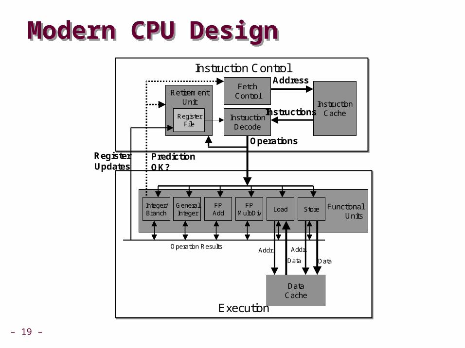
Modern CPU DesignModern CPU Design
ExecutionExecution
FunctionalUnits
Instruction ControlInstruction Control
Integer/Branch
FPAdd
FPMult/Div
Load Store
InstructionCache
DataCache
FetchControl
InstructionDecode
Address
Instructions
Operations
PredictionOK?
DataData
Addr. Addr.
GeneralInteger
Operation Results
RetirementUnit
RegisterFile
RegisterUpdates

– 20 –
Instruction ControlInstruction Control
Grabs Instruction Bytes From MemoryGrabs Instruction Bytes From Memory Based on Current PC + Predicted Targets for Predicted Branches Hardware dynamically guesses whether branches taken/not taken
and (possibly) branch target
Translates Instructions Into Translates Instructions Into OperationsOperations Primitive steps required to perform instruction Typical instruction requires 1–3 operations
Converts Register References Into Converts Register References Into TagsTags Abstract identifier linking destination of one operation with sources
of later operations
Instruction ControlInstruction Control
InstructionCache
FetchControl
InstructionDecode
Address
Instructions
Operations
RetirementUnit
RegisterFile
Instruction ControlInstruction Control
InstructionCache
FetchControl
InstructionDecode
Address
Instructions
Operations
RetirementUnit
RegisterFile

– 21 –
ExecutionUnitExecutionUnit
Multiple functional unitsEach can operate in independently
Operations performed as soon as operands availableNot necessarily in program orderWithin limits of functional units
Control logicEnsures behavior equivalent to sequential program execution
ExecutionExecution
FunctionalUnits
Integer/Branch
FPAdd
FPMult/Div
Load Store
DataCache
PredictionOK?
DataData
Addr. Addr.
GeneralInteger
Operation Results
RegisterUpdates
Operations

– 22 –
CPU Capabilities of Pentium IIICPU Capabilities of Pentium IIIMultiple Instructions Can Execute in ParallelMultiple Instructions Can Execute in Parallel
1 load 1 store 2 integer (one may be branch) 1 FP Addition 1 FP Multiplication or Division
Some Instructions Take > 1 Cycle, but Can be PipelinedSome Instructions Take > 1 Cycle, but Can be Pipelined Instruction Latency Cycles/Issue Load / Store 3 1 Integer Multiply 4 1 Integer Divide 36 36 Double/Single FP Multiply 5 2 Double/Single FP Add 3 1 Double/Single FP Divide 38 38

PentiumPro Block DiagramPentiumPro Block Diagram
P6 MicroarchitectureP6 Microarchitecture PentiumPro Pentium II Pentium III
Microprocessor Report2/16/95

– 24 –
PentiumPro OperationPentiumPro Operation
Translates instructions dynamically into “Uops”Translates instructions dynamically into “Uops” 118 bits wide Holds operation, two sources, and destination
Executes Uops with “Out of Order” engineExecutes Uops with “Out of Order” engine Uop executed when
Operands availableFunctional unit available
Execution controlled by “Reservation Stations”Keeps track of data dependencies between uopsAllocates resources
– 25 –
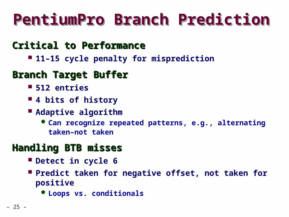
PentiumPro Branch PredictionPentiumPro Branch Prediction
Critical to PerformanceCritical to Performance 11–15 cycle penalty for misprediction
Branch Target BufferBranch Target Buffer 512 entries 4 bits of history Adaptive algorithm
Can recognize repeated patterns, e.g., alternating taken–not taken
Handling BTB missesHandling BTB misses Detect in cycle 6 Predict taken for negative offset, not taken for positive
Loops vs. conditionals

– 26 –
Example Branch PredictionExample Branch Prediction
Branch History Branch History Encode information about prior history of branch
instructions Predict whether or not branch will be taken
State MachineState Machine Each time branch taken, transition to right When not taken, transition to left Predict branch taken when in state Yes! or Yes?
T T T
Yes! Yes? No? No!
NT
T
NT NT
NT

– 27 –
Pentium 4 Block DiagramPentium 4 Block Diagram
Next generation microarchitecture
Intel Tech. JournalQ1, 2001

– 28 –
Pentium 4 FeaturesPentium 4 Features
Trace CacheTrace Cache
Replaces traditional instruction cache Caches instructions in decoded form Reduces required rate for instruction decoder
Double-Pumped ALUsDouble-Pumped ALUs Simple instructions (add) run at 2X clock rate
Very Deep PipelineVery Deep Pipeline 20+ cycle branch penalty Enables very high clock rates Slower than Pentium III for a given clock rate
L2 Cache Instruct.Decoder
TraceCache
IA32Instrs.
uops
Operations

– 29 –
Processor SummaryProcessor Summary
Design TechniqueDesign Technique Create uniform framework for all instructions
Want to share hardware among instructions
Connect standard logic blocks with bits of control logic
OperationOperation State held in memories and clocked registers Computation done by combinational logic Clocking of registers/memories sufficient to control overall
behavior
Enhancing PerformanceEnhancing Performance Pipelining increases throughput and improves resource
utilization Must make sure maintains ISA behavior