Wrap Spring Clutches and Clutch/Brakes - Tri-State … · Application Examples 4 Warner Electric...
40
Wrap Spring Clutches and Clutch/Brakes
Transcript of Wrap Spring Clutches and Clutch/Brakes - Tri-State … · Application Examples 4 Warner Electric...
Wrap SpringClutches and
Clutch/Brakes

Check Outwarnerelectric.comwarnerelectric.comwarnerelectric.com now features our new interactive eCATALOG making it faster and easierto find and spec the motion control products you need.Within the Warner Electric Interactive eCATALOG, you can start yoursearch for basic components, such as clutches or brakes, and then quickly refine your search from hundreds of possibilities to one thatmeets your specific power transmission requirements for NEMA,input/output configurations and other factors. You can also downloadspecifications and PDF pages or submit an RFQ for any of your selections.
Find it fast at www.warnerelectric.com
Warner Electric
Warner Electric offers a completeline of standard wrap spring clutchesand clutch/brakes, available forimmediate delivery through ournationwide network of power trans-mission distributors. As the industryleader in clutch/brake technologyyou can count on Warner Electric forcomplete application assistance andafter sale service.
Warner Electric 800-825-6544 1
Introduction
Wrap Spring Product Line . . . . . . . . . . . . . . . . . . .2
Principle of Operation . . . . . . . . . . . . . . . . . . . . .3
Application Examples . . . . . . . . . . . . . . . . . . . . . .4
Selection . . . . . . . . . . . . . . . . . . . . . . . . . . . . . . . . . .6
CB Mounting Requirements . . . . . . . . . . . . . . .8
CB Stop Collar Adjustment . . . . . . . . . . . . . . .10
CB Spring Differential Setting . . . . . . . . . . . .11
CB Series Clutch/Brakes
Features . . . . . . . . . . . . . . . . . . . . . . . . . . . . . . . .12
Specifications/How-to-Order . . . . . . . . . . . . . . .13
Dimensions . . . . . . . . . . . . . . . . . . . . . . . . . . .14-18
SCB Series Clutch/Brakes
Features . . . . . . . . . . . . . . . . . . . . . . . . . . . . . . . .19
Specifications/How-to-Order . . . . . . . . . . . . . . .20
Dimensions . . . . . . . . . . . . . . . . . . . . . . . . . . .21-23
WSC Series Clutches
Features . . . . . . . . . . . . . . . . . . . . . . . . . . . . . . . .24
Specifications/How-to-Order . . . . . . . . . . . . . . .25
Dimensions . . . . . . . . . . . . . . . . . . . . . . . . . . .26-29
Power Supplies . . . . . . . . . . . . . . . . . . . . . . . .30-31
Application Engineering . . . . . . . . . . . . . . . . .32-34
Part Numbers . . . . . . . . . . . . . . . . . . . . . . . . . . . . .35
Application Data Form . . . . . . . . . . . . . . . . . . . . .36
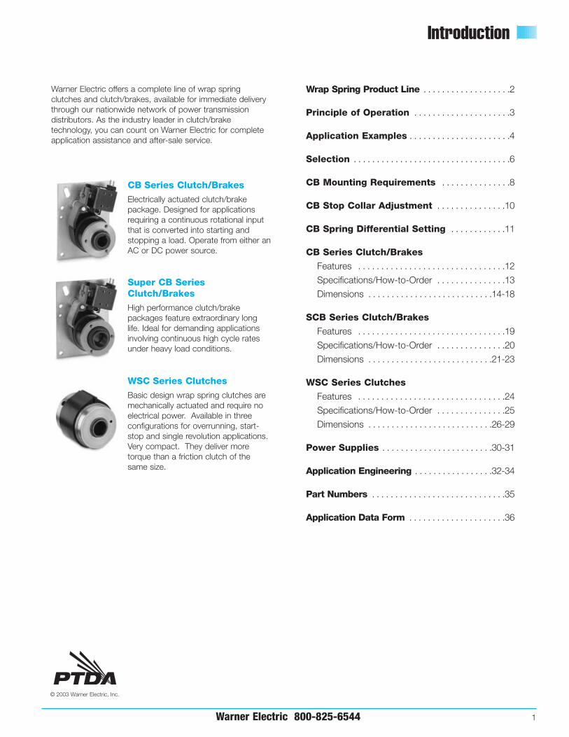
Warner Electric offers a complete line of wrap springclutches and clutch/brakes, available for immediate deliverythrough our nationwide network of power transmissiondistributors. As the industry leader in clutch/braketechnology, you can count on Warner Electric for completeapplication assistance and after-sale service.
CB Series Clutch/Brakes
Electrically actuated clutch/brakepackage. Designed for applicationsrequiring a continuous rotational inputthat is converted into starting andstopping a load. Operate from either anAC or DC power source.
Super CB SeriesClutch/Brakes
High performance clutch/brakepackages feature extraordinary longlife. Ideal for demanding applicationsinvolving continuous high cycle ratesunder heavy load conditions.
WSC Series Clutches
Basic design wrap spring clutches aremechanically actuated and require noelectrical power. Available in threeconfigurations for overrunning, start-stop and single revolution applications.Very compact. They deliver moretorque than a friction clutch of thesame size.
© 2003 Warner Electric, Inc.
2 Warner Electric 800-825-6544
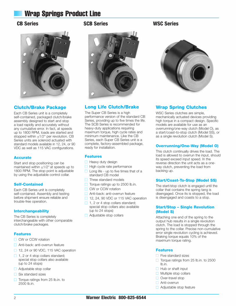
Wrap Springs Product Line
Wrap Spring ClutchesWSC Series clutches are simple,mechanically actuated devices providinghigh torque in a compact design. Specificmodels are available for use as anoverrunning/one-way clutch (Model O), asa start/coast-to-stop clutch (Model SS), oras a single revolution clutch (Model S).
Overrunning/One-Way (Model O)This clutch continually drives the load. Theload is allowed to overrun the input, shouldits speed exceed input speed. In thereverse direction the unit acts as a one-way clutch, preventing the load frombacking up.
Start/Coast-To-Stop (Model SS)The start/stop clutch is engaged until thecollar that contains the spring tang isdisengaged. Once its is stopped, the loadis disengaged and coasts to a stop.
Start/Stop – Single Revolution(Model S)Attaching one end of the spring to theoutput hub results in a single revolutionclutch. The load is stopped through thespring to the collar. Precise non-cumulativeerror single revolution cycling is achieved.Braking torque equals 10% of themaximum torque rating.
Featuresnn Five standard sizesnn Torque ratings from 25 lb.in. to 2500
lb.in.nn Hub or shaft inputnn Multiple stop collarsnn Over-travel stopnn Anti-overrunnn Adjustable stop feature
Clutch/Brake PackageEach CB Series unit is a completely self-contained, packaged clutch/brakeassembly designed to start and stop a load rapidly and accurately without any cumulative error. In fact, at speeds up to 1800 RPM, loads are started andstopped within +1/2° per revolution. CBSeries units are solenoid actuated withstandard models available in 12, 24, or 90VDC as well as 115 VAC configurations.
AccurateStart and stop positioning can bemaintained within +1/2° at speeds up to1800 RPM. The stop point is adjustableby using the adjustable control collar.
Self-ContainedEach CB Series unit is completely self-contained. Assembly and testingbefore shipment ensure reliable andtrouble-free operation.
InterchangeabilityThe CB Series is completelyinterchangeable with other comparableclutch/brake packages.
Featuresnn CW or CCW rotation
nn Anti-back: anti-overrun feature
nn 12, 24 or 90 VDC, 115 VAC operation
nn 1, 2 or 4 stop collars standard;special stop collars also available (up to 24 stops)
nn Adjustable stop collar
nn Six standard sizes
nn Torque ratings from 25 lb.in. to 2500 lb.in.
SCB Series WSC SeriesCB Series
Long Life Clutch/Brake The Super CB Series is a highperformance version of the standard CBSeries, providing up to five times the life.The SCB Series is recommended forheavy-duty applications requiringmaximum torque, high cycle rates andminimum maintenance. Like the CBSeries, each Super CB Series unit is acomplete, factory-assembled package,ready for installation.
Featuresnn Heavy duty designnn High cycle rate performancenn Long life - up to five times that of a
standard CB modelnn Three standard modelsnn Torque ratings up to 2500 lb.in.nn CW or CCW rotationnn Anti-back: anti-overrun featurenn 12, 24, 90 VDC or 115 VAC operationnn 1, 2 or 4 stop collars standard;
special stop collars also available (up to 24 stops)
nn Adjustable stop collars
Basic Design Principal
Warner Electric 800-825-6544 3
Brake control tang
Stationary brake hub
Clutchcontrol tang
Input Hub
Output shaft
Input Output
Control Tang
Design Configurations
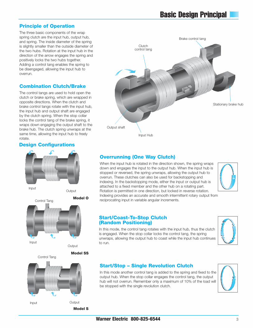
Overrunning (One Way Clutch)When the input hub is rotated in the direction shown, the spring wrapsdown and engages the input to the output hub. When the input hub isstopped or reversed, the spring unwraps, allowing the output hub tooverrun. These clutches can also be used for backstopping andindexing. In the backstopping mode, either the input or output hub isattached to a fixed member and the other hub on a rotating part.Rotation is permitted in one direction, but locked in reverse rotation.Indexing provides an accurate and smooth intermittent rotary output fromreciprocating input in variable angular increments.
Start/Coast-To-Stop Clutch (Random Positioning)In this mode, the control tang rotates with the input hub, thus the clutchis engaged. When the stop collar locks the control tang, the springunwraps, allowing the output hub to coast while the input hub continuesto run.
Start/Stop – Single Revolution ClutchIn this mode another control tang is added to the spring and fixed to theoutput hub. When the stop collar engages the control tang, the outputhub will not overrun. Remember only a maximum of 10% of the load willbe stopped with the single revolution clutch.
InputOutput
InputOutput
Control Tang
Model SS
Model S
Model O
Principle of OperationThe three basic components of the wrapspring clutch are the input hub, output hub,and spring. The inside diameter of the springis slightly smaller than the outside diameter ofthe two hubs. Rotation at the input hub in thedirection of the arrow engages the spring andpositively locks the two hubs together.Adding a control tang enables the spring tobe disengaged, allowing the input hub tooverrun.
Combination Clutch/BrakeThe control tangs are used to hold open theclutch or brake spring, which are wrapped inopposite directions. When the clutch andbrake control tangs rotate with the input hub,the input hub and output shaft are engagedby the clutch spring. When the stop collarlocks the control tang of the brake spring, itwraps down engaging the output shaft to thebrake hub. The clutch spring unwraps at thesame time, allowing the input hub to freelyrotate.

Application Examples
4 Warner Electric 800-825-6544
The features of wrap spring clutches and brakes;accuracy, repeatability, high torque-to-size ratio, lowpower consumption and long life make them an idealsolution for a wide range of motion control applications.Basic functions include overrunning, single revolution,random positioning start-stop, high cycle rate rapid start-stops and accurate, repeatable positioning.
Typical Applications
nn Conveyors
nn Rotary indexing tables
nn Packaging equipment
nn Bagging machinery
nn Collators
nn Cut-off machines
nn Vending machines
nn Copiers
nn Food processing equipment
nn Paper feeds
nn Folders
nn Material handling equipment
nn Riveters, staplers and stitching machines
nn Sorters
nn Punch presses
nn Textile machines
nn Film and wire processing
Application Examples
Incline Conveyor
The WSC Model O mechanical wrap spring clutch provides maintenance free anti-backup protection for this incline conveyor. While the conveyor is running, the wrap spring is in overrunning mode, allowing the clutch’soutput to freewheel. When the conveyor drive power is removed, eitherintentionally or unintentionally, the spring holds the hub stationary and willprevent the conveyor and its load from back-driving.
Indexing Rotary Table
Each time the power supply provides a pulse to the solenoid of theStandard CB wrap spring clutch/brake, the table indexes one position forfilling, labeling, sorting, staging or inspecting products. CB, Super CB or WSC Model S (with customer supplied actuator) units may each be used to perform the indexing function. Please note that while thegraphic shows open gearing, a standard enclosed gearbox will work just as effectively.

Warner Electric 800-825-6544 5
Application Examples
Industrial Stitchers and Staplers
The motor drives a large flywheel and a cam connected to thestitcher head. The CB or Super CB wrap spring clutch/brakeprovides one complete cycle, always stopping at the same preciseposition in time for the next cycle. Warner Electric’s CB and SuperCB units never require any adjustment or lubrication, and providenon-cumulative error for cycle-to-cycle accuracy and consistency.
Rack and Pinion Indexing
The unidirectional WSC Model O operates as an indexing drive for this application. As the rack moves upward, the wrap springdrives, providing torque to the in-feed rolls. When the rack movesdownward, the wrap spring clutch freewheels, transmitting notorque to the rolls. Since the cam, pinion gear and rolls are allconstant diameters, coupled with the accuracy of the WSC, the amount fed each cycle remains constant and consistent.
Print Head
In this printing application, a photoelectric sensor detects the registration mark on the web and signals the CB orSuper CB clutch/brake to cycle. Each cycle drives the print wheel in registration with the continuously moving web material.Warner Electric wrap spring clutch/brakes provide start and stop positioning within a ± 1/2° per revolution (non-cumulative),making them an excellent solution for applications requiring highly accurate, consistent performance.
Cut-Off Knife
As tubing material is fed, a sensor determines when theappropriate length has been reached, and signals the lutch/braketo cycle, driving the knife to cut the tubing to the correct length.This application shows a standard option two-stop collar, which indexes 180° per sensor input, making two cuts per onecomplete 360° revolution. The CB or Super CB clutch/brakeprovides error free indexing, making the reaction time for the knife consistent from cycle-to-cycle.

Selection
6 Warner Electric 800-825-6544
Max. TorqueFunction Performance Wrap Spring Starting Stopping Max. Actuation
Product lb. in. lb. in. RPM Method(N-m) (N-m)
marginally within the capabilities of aspecific product, consider using the nextlarger size. In instances where requiredload/speed performance data is knownand unit size is uncertain, use thetechnical selection process starting onpage 28 which will help you review thenecessary aspects of your application.
Step 1 Determine clutch or brakefunction
Wrap spring clutches and brakes canperform three control functions—overrunning, start/coast-to-stop, andsingle revolution. Determine the functionwhich will provide the best control foryour application. Using the chart below,select the series which best fits yourapplication requirements.
Step 2 Determine size
To select the correct size unit, determinethe maximum RPM at which the clutch or brake will be operated and the shaftdiameter on which the wrap spring unitwill be mounted. A wrap spring clutchengages almost instantly, and, sincespring wrap increases with load, the unitmust be sized carefully to insure that it iscorrect for the application. If there is anyuncertainty regarding the correct unitsize, we recommend using the technicalselection process starting on page 32. Toselect the correct wrap spring unit, locatethe corresponding speed and shaftdiameter points on the appropriate charton page 7. For applications requiringspeed or diameter values higher thanthose illustrated, please contact yourlocal Warner Electric Distributor, yourMarket Representative, or Warner ElectricTechnical Support at (800) 825-9050.
Selection by Function
For Product SelectionFollow 3 Easy StepsWrap spring clutches and brakes are pre-packaged, pre-assembled unitswhich are as easy to select as they are to install. The simple three step selectionprocess includes:
Step 1 Determine the clutch or brake function
Step 2 Determine size
Step 3 Verify design considerations
This selection process is based on theassumption that the diameter of the shaftat the clutch or clutch/brake location hasbeen designed through good machinedesign practice. For most applications,this process will determine the correctsize product. When the performancerequirements of a given application are
Overrunning
Start/Coast-To-Stop
Single Revolution
Accurate positioningfor single or multiplestops
Random Positioning
An overrunning clutch willtransmit torque in one directiononly when the input hub isstopped or reversed.Consequently, the load isdisengaged and free to rotate oroverrun.
WSC SeriesModel O
2,500(282.5)
N/A 1,800 Reverse inputrotation
A start/coast-to-stop clutch willengage and disengage a loadeither by mechanical orelectrical actuation. Start/coast-to-stop clutches provide arandom stop position for theload.
WSC SeriesModel SS
2,500(282.5)
0 1,800 Mechanical
A single revolution clutch orclutch/brake will accuratelyposition a load with nocumulative error for each singlerevolution cycle. Multiple stopcollars with up to 24 stops (perrevolution) provide fractionalrevolution capability.
WSC SeriesModel S
Super CB
Standard CB
2,500(282.5)
2,500(282.5)
2,500(282.5)
250(282.5)
2,500(282.5)
2,500(282.5)
1,800
750
1,800
Mechanical
AC or DCSolenoid
AC or DCSolenoid
Engaged in one direction only

Selection
Warner Electric 800-825-6544 7
Step 3Verify design function considerationsOnce the appropriate series and modelsize have been determined, review thedesign considerations. A completechecklist of these and other optionsavailable are detailed in the How to Order section for each series.
2
6
6
4
5
1/43/81/23/4
1
ClutchSize Bore Size
RPM
200 300 400 500 600 700 800 900 1000 1100 1200 1300 1500 1700 18001400 1600
8
8
8
8
1*
11/4
13/8*
11/2
* Special Order
2
6
6
8
8
8
8
4
5
1/43/81/23/4
1
1
11/4
13/8
11/2
ClutchSize Bore Size
RPM
200 300 400 500 600 700 800 900 1000 1100 1200 1300 1400 1500 1600 1700 1800
Selection Charts – RPM vs. Shaft Diameter
Super CB and Standard CB Series
WSC Series
Design Considerations
All Models
nn CW or CCW rotationnn Single or multiple stop collarnn Bore size
Super CB and CB Series
nn AC or DC solenoidnn CB-5, CB-6 and CB-8 sizes available
in the long life, Super CB Series. Seepages 19–23 for specific details.
WSC Series
nn Hub input/shaft output or shaftinput/hub output
nn Overrunning Model O, start/coast-to-stop Model SS or single revolutionModel S

CB Mounting Requirements
8 Warner Electric 800-825-6544
CB Mounting RequirementsMaximum Radial Bearing Load atMaximum Speed
CB-2 = 7.5 lbs.CB-4 = 14 lbs.CB-5/Super CB-5 = 32 lbs.CB-6/Super CB-6 = 63 lbs.CB-8/Super CB-8 = 300 lbs.
CB and Super CB style clutch/brakes aredesigned for horizontal shaft mounting.While it is possible to mount unitsvertically, vertically mounted units will seelower life than those mounted horizontallydue to the wear between hubs resultingfrom gravity.
Horizontal MountingFigure 1 illustrates an ideal CB mounting.The unit is attached to the output shaftwith both a key and set screws. The plateis restrained from rotating, but not fromaxial movement, reducing the side load onthe CB’s internal plate bearing.
In cases where easy access to the input is desirable, the clutch/brake can bemounted on a stub shaft. However, theunit must still be fully supported, whileoverhung loads on the input member mustbe avoided to maintain the life of the radialbearing.
Figures 2 and 3 illustrate alternatemounting configurations for achievingproper support. Inputs are usually face-mounted to the input hub of the CB unitas shown in Figure 1. This type ofmounting is facilitated by the drilled andtapped holes provided in the free hubflange. The configuration shown in Figure2 is a possibility, if the radial load on theinput hub of the CB is small compared to the specified load.
If the application contains a substantialradial bearing load, arrange the pulleyover the centerline of the clutch free hub as illustrated in Figure 3. Place one support bearing as close to thepulley as possible, using a torque arm for anti-rotation.
The smaller CB units (sizes 2, 4 and 5)have pilot holes in the output shaft,which guide drilling through the machineshaft for attaching the unit with a pin.
While Warner Electric wrap springclutches are self-contained, packagedproducts, which are easy to mount, a fewsimple precautions should be taken toensure maximum life.
All Warner Electric wrap spring clutchproducts are designed to be installed inparallel shaft applications where they arefully supported by the shaft on which theyare mounted.
Each clutch/brake backing plate assemblyhas three or four mounting holes, plus ananti-rotation slot, and is designed to serveas a torque arm rather than as a rigidmounting plate. The plate should berestrained from rotating by a pin orshoulder bolt, while allowing for the plateto float axially. The anti-rotation devicemust be capable of withstanding thebraking torque required by the load.
Important: Do not rigidly mount unit.Plate must be allowed to “float” axially.
On CB type units, the input rotation isalways connected to the input hub, andthe output is always through the shaftthrough the hollow bore of theclutch/brake.
Connecting the unit to the parallel shaftmay be accomplished by pinning (forsizes 2, 4, and 5) or by key and set screw(for sizes 6 and 8).
When connecting the parallel shaft to theCB by using a belt, chain or gear drive,the input hub’s radial bearing loadcapacity must not be exceeded. (Seechart in next column). It may benecessary to counter bore or bearingmount the input pulley sprocket or gear.
Double Bearing Support for Stub Shaft
Input Member Inboard
++
+
+ +
++
++++
PotentialMounting
Holes
PotentialMounting
Holes
Anti-Rotation Slot
Clockwise Rotation Shown
Clutch fully supported by the shaft with bearing support on both ends
Customer's Input member counterbored to center mass
over clutch bearing
Plate restrained from rotating by pin or shoulder bolt. No axial binding.
+
Figure 1
Figure 3
Customer's Bearing-Mounted Pulley
Double Bearing Support for Stub Shaft
Set Collar
Pin Drive Not Bolted
to InputSecure Pulley
to Hub
Figure 2
Warner Electric 800-825-6544 9
CB Mounting Requirements
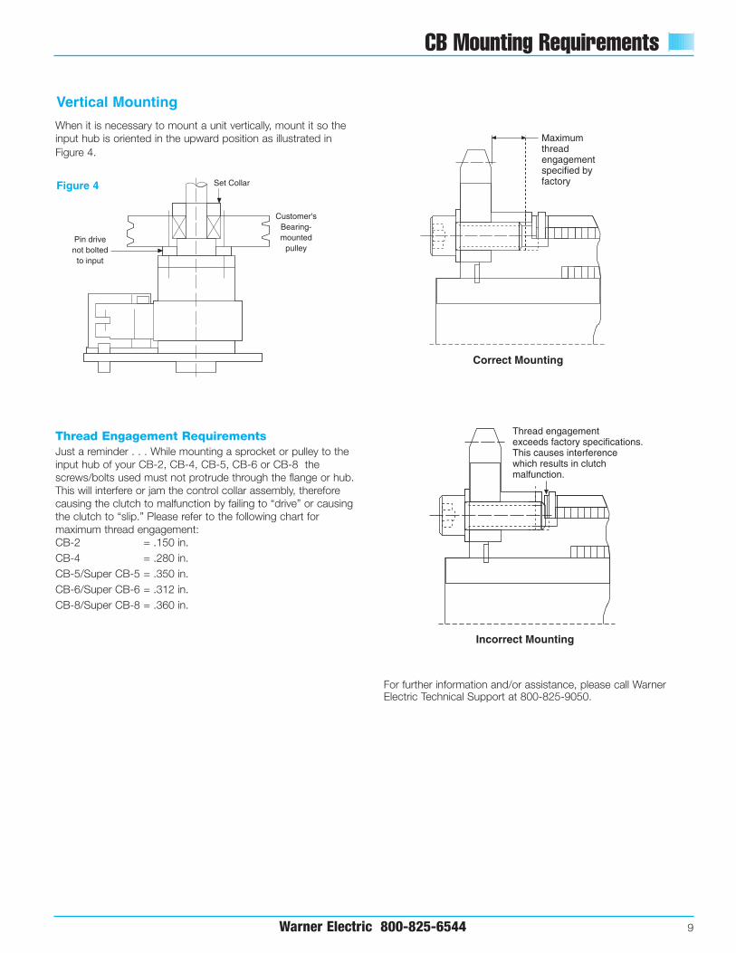
When it is necessary to mount a unit vertically, mount it so theinput hub is oriented in the upward position as illustrated inFigure 4.
Thread Engagement RequirementsJust a reminder . . . While mounting a sprocket or pulley to theinput hub of your CB-2, CB-4, CB-5, CB-6 or CB-8 thescrews/bolts used must not protrude through the flange or hub.This will interfere or jam the control collar assembly, thereforecausing the clutch to malfunction by failing to “drive” or causingthe clutch to “slip.” Please refer to the following chart formaximum thread engagement:CB-2 = .150 in.CB-4 = .280 in.CB-5/Super CB-5 = .350 in.CB-6/Super CB-6 = .312 in.CB-8/Super CB-8 = .360 in.
Vertical Mounting
Pin drivenot bolted
to input
Customer'sBearing-mounted
pulley
Set CollarFigure 4
Maximum thread engagementspecified by factory
Correct Mounting
Thread engagement exceeds factory specifications.This causes interferencewhich results in clutch malfunction.
Incorrect Mounting
For further information and/or assistance, please call WarnerElectric Technical Support at 800-825-9050.

10 Warner Electric 800-825-6544
CB Stop Collar Adjustment
CB Stop Collar Adjustment
Each CB and Super CB Series unit has an incrementallyadjustable collar, which allows for changes to the output orientation.
RetainingRing
StopCam
Sleeve
Adjustment Increments With Standard Stop Collars
CB-2 Infinitely AdjustableCB-4 2.4º AdjustableCB-5/Super CB-5 1.8º AdjustableCB-6/Super CB-6 1.8º AdjustableCB-8/Super CB-8 1.6º Adjustable
Retaining Ring
Sleeve
Stop Cam
To adjust the stop collar output orientation:
• Wrap the brake spring down completely by rotating the output shaft in the driving direction until it cannot travel any further;
• Remove the retaining ring from its groove and slide it forward on the sleeve; then,
• Hold the actuator clear, while sliding the stop cam off the sleeve.Rotate the cam to the desired stop position, and slide it back onto the sleeve; and,
• Slide the retaining ring back into position.

Warner Electric 800-825-6544 11
CB Spring Differential Setting
8. If the overtravel measurement is within these specified limits,reinstall the retaining ring and the unit’s overtravel is reset.
9 A. If the overtravel exceeds the specified limit, move the brakespring backwards one slot (against the direction of rotation)and repeat steps two through seven.
B. If the overtravel is less than the specified limit, move thebrake spring forward one slot (in the direction of rotation,)and repeat steps two through seven.
If Spring Replacement Is Not Required
If the unit is disassembled and the drive and/or brake springsdo not need to be replaced, proceed as follows:
• Reposition the drive and brake springs into their originalpositions onto the output shaft assembly.
• Reassemble the clutch, and position the spring tangs of thedrive and brake springs in the factory marked locations on thecontrol collar assembly (on the control collar, the designatedtang slots are indicated with punch marks on either side of each slot).
• After the unit is completely reassembled, the differential settingshould match that of the original factory setting.
CB Spring Differential Setting
All CB and Super CB Series clutch/brakes are factory-set to theproper spring differential overtravel. If a spring must be replaced,prior to disassembly, make sure the two spring tang slots aremarked to help ensure proper reassembly. (There should bepunch marks from the factory on either side of the spring tangslots marking those used for the correct differential setting.) If the slots are unmarked and the unit has been disassembled,use the following procedure to reset the spring differential.
1. Remove the retaining ring from the input hub.
2. Rotate the clutch so the brake spring is fully wrapped downby rotating the output shaft in the driving direction until itcannot travel any farther.
3. With the brake fully engaged (per step 2), pull the input hubassembly out, and push the clutch spring out of its slot,allowing it to jump to wherever it comes to rest.
4. Unwrap the clutch spring and push it backwards into thenearest slot.
5. Push the input hub back into place, release the actuator, androtate the clutch until the brake spring fully wraps down again.
6. With the brake fully engaged (wrapped down per step 2), holdthe shaft with one hand and release the actuator. The stopcollar will rotate forward as the brake is released and theclutch engages.
7. To calculate the overtravel, use a scale to measure the distance between the tip of the actuator, and the tip of the stop on the cam
The Amount of Acceptable Overtravel Varies with theSize of the Unit
CB-2 .09 to .19"CB-4 .09 to .19"CB-5/Super CB-5 .09 to .19"CB-6/Super CB-6 .22 to .38"CB-8/Super CB-8 .39 to .60"
+
+
+
Overtravel/DifferentialSetting

CB Series Clutch/Brakes
12 Warner Electric 800-825-6544
Combination Clutch/Brake Packages
CB Series clutch/brake combinations aredesigned for applications requiring acontinuous rotational input beingconverted into starting and stopping aload. To start motion, the solenoid ispulsed, moving the actuator arm awayfrom the control collar. This allows theclutch spring to wrap (wind) down ontothe output assembly while the brakespring is unwinding, allowing the outputto drive. Motion is stopped when theactuator returns to its rest position andthe control collar rotates, stoppingagainst the actuator. This forces theclutch spring to unwind releasing theinput from the output and wraps thebrake spring down, stopping the output.Anti-back and anti-overrun springsmaintain position accuracy by eliminatingany backward movement or bouncewhen stopped. The actual stoppingposition can be adjusted after installationby moving the splined cam of the controlcollar assembly.
The input hub is drilled and tapped to allow for mounting of sprockets,gears, sheaves, etc. The output is a hollow quill that mounts onto thecustomer’s driven shaft. The backingplate is not mounting plate. It must be held in place by a loose fit pin to eliminate any side or radial loads from preloading the unit’s bearings.
Features
nn Stop Position Accuracy ±1/2°
nn Adjustable Output Stop Positions
nn Standard Features
– CW or CCW Rotation– Hub Input – Shaft Output– Anti-Overrun Output does not
overrun Input– Anti-Back Output does not Backup
nn 1, 2 and 4 stop collars for 360°, 180°,and 90° output increments standard
– Special multi-stop collars alsoavailable (up to 24 stops)
nn 115 VAC and 24 VDC SolenoidsStandard
– Other Voltages Available
nn Dimensionally Interchangeable WithCompetitive Units
nn 5 Standard ModelsCB-2CB-4CB-5CB-6CB-8

CB Series Clutch/Brake
Warner Electric 800-825-6544 13
These clutch/brakes (except CB-2) offerunique splined stop collars which can beadjusted radially in fine increments. Thisfeature allows the user to reposition theoutput to comply with specified shaft and keyway placements. Standard stopcollar positioning increments are shownbelow for all models:
CB-2 Infinitely AdjustableCB-4 2.4° AdjustableCB-5 1.8° AdjustableCB-6 1.8° AdjustableCB-8 1.6° Adjustable
Basic SelectionSee pages 6–7 for basic productselection guidelines.
For complete Application Engineeringinformation see pages 32–34.
Specifications CB-2 CB-4 CB-5 CB-6 CB-8
Static Torque 25 lb.in. 120 lb.in. 250 lb.in. 500 lb.in. 2,500 lb.in.(2.825 N-m) (13.56 N-m) (28.25 N-m) (56.5 N-m) (282.5 N-m)
Maximum anti-overrun 10 lb.in. 25 lb.in. 45 lb.in. 300 lb.in. 600 lb.in. holding capability (1.13 N-m) (2.825 N-m) (5.085 N-m) (33.9 N-m) (67.8 N-m)
Maximum anti-back 10 lb.in. 80 lb.in. 160 lb.in. 300 lb.in. 600 lb.in. holding capability (2.034 N-m) (9.04 N-m) (18.08 N-m) (33.9 N-m) (67.8 N-m)
Inertia, rotating parts .034 lb.in.2 .064 lb.in.2 .195 lb.in.2 1.718 lb.in.2 12.84 lb.in.2
Maximum radial bearing 7.5 lbs. 14 lbs. 32 lbs. 63 lbs. 300 lbs.load at maximum speed
Maximum operating speed 1,800 RPM 1,200 RPM 750 RPM 500 RPM 300 RPM
Response time, voltage on 20 MS 24 MS 27 MS 45 MS 50 MSat full speed
Weight 1 lb. 2 lbs. 3 lbs. 7 lbs. 15 lbs.
See page 32 for Minimum Inertia Requirements.See page 8 for Mounting Examples.
Control Collars
A one, two or four stop collar is standardon CB Series clutch/brakes. A variety of stop collar configurations, upto 24 stops maximum, are available.Consult Warner Electric Technical Supportat 800-825-9050 for complete information.
Optional Multiple Stop Collars
Order by part number (see chart ondimensions page) or specify as follows.
Specify:
1. Series CBEnglish Metric
2. Size: CB-2, CB-4, CB-5, CB-6, CB-8 3. Direction of rotation:
CW ClockwiseCCW Counterclockwise
4. Coil voltage:115 AC or 24 DC are standard12 DC or 90 DC are options
5. Bore size:CB-2 = 1⁄4"CB-4 = 3⁄8"CB-5 = 1⁄2"CB-6 = 3⁄4" or 1"CB-8 = 11⁄4" or 11⁄2" standard
1" or 13⁄8" special order6. Stop collar:
1, 2 or 4 stops standardOther stop collars are available asspecials
Example: CB-8, CCW, 115VAC, 1" bore, 4 stop collar.
How to Order
RetainingRing
DriveSleeve
StopCam
CouplingSleeve
BrakeSleeve
RetainingRing
StopCam
Sleeve
CB -8 CCW 115VAC 1" 4
1 2 3 4 5 6

CB-2 Clutch/Brake
14 Warner Electric 800-825-6544
Dimensions in. (mm)
Bore Sizes
Bore Pin Hole Mtg. Holes Set ScrewsA B C D
English in. .2505-.253 .062 3x #6-32 Eq. Sp. #8(mm) (6.3627-6.4262) (1.5748) on .938 BC SHCS
Metric mm 6.0 H9 1.5 3x M4 x 0.7 Eq. Sp. M4 x 0.7(in.) (.2362-.2374) (.055–.062) on 23.83 BC SHCS
All dimensions are nominal unless otherwise noted.
Specifications
Static Torque 25 lb.in.
Maximum anti-overrun holding capability 10 lb.in.
Maximum anti-back holding capability 10 lb.in.
Inertia, rotating parts .034 lb.in.2
Maximum radial bearing load at maximum speed 7.5 lbs.
Maximum operating speed 1800 RPM
Response time, voltage on at full speed 20 MS
Weight 1 lb.
20˚
2.00(50.80)
3.39(86.106)
.710(18.034)
1.00(25.4)
1.00(25.4)
4 x .187 (4.75) DiaEq. Sp. on 2.125 (53.975) BC
.198 (5.03) x .375 (9.525) Long
1.95(49.53)
C
2 x .25 (6.35) Nom Wd. x .03 (0.77) Nom Thk. Spade Lug
B
D
A
1.57(39.878)
.375(9.525)
.09(2.286)
.21(5.334)
1.188(30.175)
.868(22.0472)
.02(.508)
.16(4.064)
.41 (10.414).09
(2.286)
2.5(63.5)
As shownviewed from
input hub onlyCCW
As shownviewed from
input. (May be shaft
or hub input.)
As shownviewed fromlug drive end
CCW
CCW
BORE DETAIL
A
Electrical Data (±10%)Current Resistance
Voltage (amps) (ohms) Status
115 AC 60 Hz .10* 825 Standard
24 DC .23 104 Standard
12 DC .46 26 Option
90 DC .06 1510 Option
(Coils are rated for continuous duty)
*115 AC—In rush current .10 amps, Holding current .05 amps
CB-2 Part NumbersBore StopsSize Voltage Rotation 1 2 40.25" 24 VDC CW 302-17-001 302-17-002 302-17-003
CCW 302-27-001 302-27-011 302-27-003
0.25" 115 VAC CW 302-17-007 302-17-008 302-17-009CCW 302-27-007 302-27-008 302-27-009
These are the most commonly requested parts – other voltages (such as 12VDC and 90VDC), bores and stop collars are available.
CB-4 Clutch/Brake
Warner Electric 800-825-6544 15
.645(16.39)
.807 (20.50)
.500(12.70)
17° 30'
4.10(104.14)
1.00(25.40)
2.56(65.02)
2.38(60.45)
1.19(30.23)
2.03(51.56)
Max
1.25(31.75)
BOne Side Only
1.248-1.250(31.699-31.75)
.15(3.81)
.33(8.38)
3.381(85.88)
.09 (2.29)
.83(21.08) .035
(0.89) Max
.14 (3.56)D
4 x .187 (4.75) Dia.Eq. Sp. on 2.125 (53.98) BC C
BOne Side Only
.26 (6.60) Wide x.50 (12.70) Long
2 x .25 (6.35) Nom Wd x .03 (0.77) Nom Thk
Spade Lug
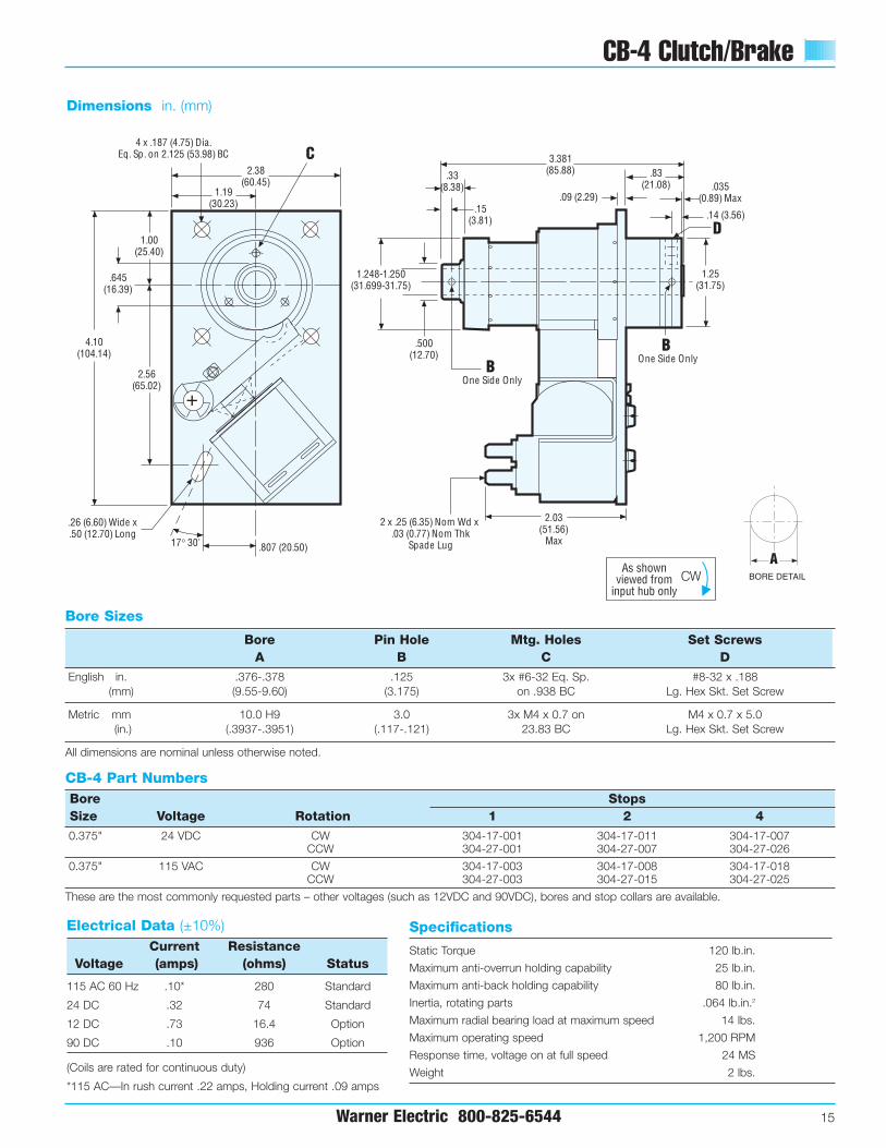
Dimensions in. (mm)
Specifications
Static Torque 120 lb.in.
Maximum anti-overrun holding capability 25 lb.in.
Maximum anti-back holding capability 80 lb.in.
Inertia, rotating parts .064 lb.in.2
Maximum radial bearing load at maximum speed 14 lbs.
Maximum operating speed 1,200 RPM
Response time, voltage on at full speed 24 MS
Weight 2 lbs.
Bore Sizes
Bore Pin Hole Mtg. Holes Set ScrewsA B C D
English in. .376-.378 .125 3x #6-32 Eq. Sp. #8-32 x .188(mm) (9.55-9.60) (3.175) on .938 BC Lg. Hex Skt. Set Screw
Metric mm 10.0 H9 3.0 3x M4 x 0.7 on M4 x 0.7 x 5.0(in.) (.3937-.3951) (.117-.121) 23.83 BC Lg. Hex Skt. Set Screw
All dimensions are nominal unless otherwise noted.
Electrical Data (±10%)Current Resistance
Voltage (amps) (ohms) Status
115 AC 60 Hz .10* 280 Standard
24 DC .32 74 Standard
12 DC .73 16.4 Option
90 DC .10 936 Option
(Coils are rated for continuous duty)
*115 AC—In rush current .22 amps, Holding current .09 amps
CB-4 Part NumbersBore StopsSize Voltage Rotation 1 2 40.375" 24 VDC CW 304-17-001 304-17-011 304-17-007
CCW 304-27-001 304-27-007 304-27-026
0.375" 115 VAC CW 304-17-003 304-17-008 304-17-018CCW 304-27-003 304-27-015 304-27-025
These are the most commonly requested parts – other voltages (such as 12VDC and 90VDC), bores and stop collars are available.
As shownviewed from
input hub onlyCW
As shownviewed from
input. (May be shaft
or hub input.)
CW
As shownviewed fromlug drive end
CW
As shownviewed from
this endCW
BORE DETAIL
A
CB-5 Clutch/Brake
16 Warner Electric 800-825-6544
2.50(63.50)
4.56(115.82)
1.31(33.27)
1.31(33.27)
2.62(66.55)
.91(23.11) 20°
4.375(111.13)
.46(11.68)
.25(6.35)
1.56(39.62)
1.09(27.69)
.09 (2.29).19 (4.83)
2.09(53.09)
.625(15.88)
1.5605-1.5625(39.64-39.69)
D
C4 x .187 (4.75)Dia
Eq. Sp. On3.125 (79.38) BC
.045(1.14)
Max
BONE SIDE ONLYB
ONE SIDE ONLY
.26 (6.60) Wide x.50 (12.70) Long
2 x .25 (6.35) Nom Wdx .03 (0.77) Nom Thk
Spade Lug
.78(19.81)
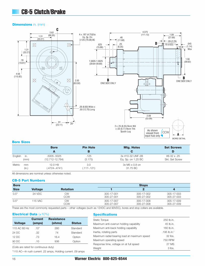
Dimensions in. (mm)
Specifications
Static Torque 250 lb.in.
Maximum anti-overrun holding capability 45 lb.in.
Maximum anti-back holding capability 160 lb.in.
Inertia, rotating parts .195 lb.in.2
Maximum radial bearing load at maximum speed 32 lbs.
Maximum operating speed 750 RPM
Response time, voltage on at full speed 27 MS
Weight 3 lbs.
Bore Sizes
Bore Pin Hole Mtg. Holes Set ScrewsA B C D
English in. .5005-.5025 .125 3x #10-32 UNF-2B #8-32 x .25(mm) (12.712-12.764) (3.175) Eq. Sp. on 1.25 BC Skt. Set Screw
Metric mm 12.0 H9 3.0 3x M5 x 0.8 on(in.) (.4724-.4741) (.117-.121) 31.75 BC
All dimensions are nominal unless otherwise noted.
Electrical Data (±10%)Current Resistance
Voltage (amps) (ohms) Status
115 AC 60 Hz .10* 280 Standard
24 DC .32 74 Standard
12 DC .73 16.4 Option
90 DC .10 936 Option
(Coils are rated for continuous duty)
*115 AC—In rush current .22 amps, Holding current .09 amps
CB-5 Part Numbers Bore StopsSize Voltage Rotation 1 2 40.5" 24 VDC CW 305-17-001 305-17-002 305-17-003
CCW 305-27-001 305-27-002 305-27-003
0.5" 115 VAC CW 305-17-007 305-17-008 305-17-009CCW 305-27-007 305-27-008 305-27-009
These are the most commonly requested parts – other voltages (such as 12VDC and 90VDC), bores and stop collars are available.
As shownviewed from
input hub onlyCCW
As shownviewed from
input. (May be shaft
or hub input.)
As shownviewed fromlug drive end
CCW
CCW
BORE DETAIL
A

CB-6 Clutch/Brake
Warner Electric 800-825-6544 17
+++
+
+ +
++
++++
4.312(109.53)
.517-.537(13.132-13.640) .125 (3.175)
.22 (5.59)
.36 (9.144).19 (4.83)
2.50(63.50)
1.559-1.562(39.59-39.68)
1.25(31.75)
2.25(57.15)
2.92(74.17)
5.75(146.05)
2.12(53.85)
4.25(107.95)
1.38(35.05)
2.12(53.85)
4 x .279-.288 (7.087-7.315) DiaEq. Sp. on 5.0 (127.0) BC E
20°
DD
2 x .25 (6.35) Nom Wd x.03 (0.77) Nom Thk
Spade Lug
.386 (9.80) Wide x.80 (20.32) Long
Dimensions in. (mm)
SpecificationsStatic Torque 500 lb.in.Maximum anti-overrun holding capability 300 lb.in. Maximum anti-back holding capability 300 lb.in. Inertia, rotating parts 1.718 lb.in.2
Maximum radial bearing load at maximum speed 63 lbs.Maximum operating speed 500 RPMResponse time, voltage on at full speed 45 MSWeight 7 lbs.
Bore & Keyway Sizes
Bore Keyway Keyway Set Screws/Pin Hole Mtg. HolesA Width B Depth C D E
English in. .7505-.7525 .1875 .09375 2x #10-32 UNF-2B 3x #1/4-20 UNC-2B(mm) (19.062-19.114) (4.7625) (2.381) Eq. Sp. on 2.062 BC
1.0005-1.0025 2x .187 Hole 3x #1/4-20 UNC-2B(25.412-25.464)
— —(4.7498) Eq. Sp. on 2.062 BC
Metric mm 20.0 H9 6.0 2.8 2x M5 x 0.8 x 5.0 3x M6 x 1.0 on(in.) (.7874-.7894) (.2362) (.1102) Lg. Hex Soc. Set Screw 52.38 BC
25.0 H9 2x 5.0 Hole 3x M6 x 1.0 on(.9842-.9862)
— —(.191-.203) 52.38 BC
All dimensions are nominal unless otherwise noted.
Electrical Data (±10%)Current Resistance
Voltage (amps) (ohms) Status
115 AC 60 Hz .33* 53.5 Standard
24 DC .60 39.9 Standard
12 DC 1.15 10.4 Option
90 DC .15 598 Option
(Coils are rated for continuous duty)
*115 AC—In rush current .62 amps, Holding current .31 amps
CB-6 Part Numbers Bore StopsSize Voltage Rotation 1 2 40.75" 24 VDC CW 306-17-051 306-17-074 306-17-162
CCW 306-27-029 306-27-046 306-27-134
0.75" 115 VAC CW 306-17-053 306-17-060 306-17-073CCW 306-27-031 306-27-039 306-27-045
1.0" 24 VDC CW 306-17-057 306-17-061 306-17-031CCW 306-27-032 306-27-147 306-27-150
1.0" 115 VAC CW 306-17-059 306-17-062 306-17-075CCW 306-27-034 306-27-044 306-27-037
These are the most commonly requested parts – other voltages (such as 12VDC and 90VDC), bores and stop collars are available.
As shownviewed from
input hub onlyCW
As shownviewed from
input. (May be shaft
or hub input.)
CW
As shownviewed fromlug drive end
CW
As shownviewed from
this endCW
BORE DETAIL
C
B
A

CB-8 Clutch/Brake
18 Warner Electric 800-825-6544
++
4.00(101.60)
2.372-2.374(60.24-60.30)
+
++
+
++
30°
++
++
+
E
7.00(177.80)
5.0(127) 2.50
(63.50)
2.50(63.50)
3.118(79.20)
1.80(45.72)
6.125(155.58)
.40(10.16)
.698 (17.73)
.25 (6.35).188 (4.78)
.427 (10.85)
1.967(49.96)
2.31(58.68)
Max
.25(6.35)
D
D
+
4 x .394 (10.0) Dia Sp. @ 90°on 5.875 (149.225) BC
.386 (9.80) Wide x
.80 (20.32) Long
Dimensions in. (mm)
SpecificationsStatic Torque 2,500 lb.in.Maximum anti-overrun holding capability 600 lb.in. Maximum anti-back holding capability 600 lb.in. Inertia, rotating parts 12.840 lb.in.2
Maximum radial bearing load at maximum speed 300 lbs.Maximum operating speed 300 RPMResponse time, voltage on at full speed 50 MSWeight 15 lbs.
Bore & Keyway Sizes
Bore Keyway Keyway Set Screws Mtg. HolesA Width B Depth C D E
English in. 1.2505-1.2525 .3125 .15625 2x #1/4-20 UNC-2B 6x 5/16-18 UNC-2B(mm) (31.762-31.814) (7.9375) (3.9688) Eq. Sp. on 3.375 BC
1.5005-1.5025 .375 .125 2x #1/4-20 x UNC-2B 6x 5/16-18 UNC-2B (38.112-38.164) (9.525) (3.175) Eq. Sp. on 3.375 BC
Metric mm 35.0 H9 10.0 3.3 2x M6 x 1.0 x 10.0 6x M8 x 1.25 on(in.) (1.3780-1.3804) (.3937) (.1299) Lg. Hex Soc. Set Screw 85.73 BC
40.0 H9 2x M6 x 1.0 x 10.0 6x M8 x 1.25 on(1.5784-1.5772)
— —Lg. Hex Soc. Set Screw 85.73 BC
All dimensions are nominal unless otherwise noted.
Electrical Data (±10%)Current Resistance
Voltage (amps) (ohms) Status
115 AC 60 Hz .33* 53.5 Standard
24 DC .60 39.8 Standard
12 DC 1.15 10.4 Option
90 DC .15 598 Option
(Coils are rated for continuous duty)
*115 AC—In rush current .62 amps, Holding current .31 amps
CB-8 Part Numbers Bore StopsSize Voltage Rotation 1 2 41.25" 24 VDC CW 308-17-101 308-17-102 308-17-103
CCW 308-27-101 308-27-102 308-27-103
1.25" 115 VAC CW 308-17-107 308-17-108 308-17-109CCW 308-27-107 308-27-108 308-27-109
1.5" 24 VDC CW 308-17-119 308-17-120 308-17-121CCW 308-27-119 308-27-120 308-27-121
1.5" 115 VAC CW 308-17-125 308-17-126 308-17-127CCW 308-27-125 308-27-126 308-27-127
These are the most commonly requested parts – other voltages (such as 12VDC and 90VDC), bores and stop collars are available.
As shownviewed from
input hub onlyCW
As shownviewed from
input. (May be shaft
or hub input.)
CW
As shownviewed fromlug drive end
CW
As shownviewed from
this endCW
BORE DETAIL
C
B
A

Super CB Series Clutch/Brakes
Warner Electric 800-825-6544 19
Long Life, High Performance Design
The Super CB Series Clutch/Brakesfunction in the same manner as thestandard CB Series. The major advantageof the Super CB Series is extraordinarylong life, up to five times longer than astandard unit. This makes the Super CBSeries the ideal choice for applicationsinvolving high cycle rates and continuousheavy-duty operation.
Super CB Series design featuresThe standard CB Series and SCB Seriesunits both employ three primary hubs thatare oil impregnated; the input hub, thebrake hub and an internal hub pinned tothe output shaft. On standard units, the oillubricates the bearing surfaces of the inputand brake hub, while the Super CB Seriesuses needle bearings in the input andbrake hubs to increase the radial bearingload capacity. Both types require oil in thehubs to lubricate the springs. The SuperCB Series units also feature hardenedsteel wear rings on the primary hubs at thecrossover point of the clutch, brake andshaft hubs to further increase life. Thecontrol collar assemblies are glassreinforced nylon, strengthened by steel oraluminum inserts. The actuators are Delrin‚
AF on all models.
Features
nn Increased life-up to five times longerthan standard models
nn Stop Position Accuracy +1/2°
nn Adjustable Output Stop Positions
nn Standard Features
– CW or CCW Rotation– Hub Input – Shaft Output– Anti-Overrun Output does not
overrun Input– Anti-Back Output does not
Backup
nn 1, 2 and 4 stop collars for 360°, 180°,and 90° output increments standard
– Special multi-stop collars alsoavailable (up to 24 stops)
nn 115 VAC and 24 VDC SolenoidsStandard
– Other Voltages Available
nn Dimensionally Interchangeable WithCompetitive Units
nn 3 Standard ModelsSCB-5SCB-6SCB-8
nn High torque in small package.
nn Actuating solenoid is AC or DCoperated.
nn Brake engages automatically when de-clutched.
nn Maintenance-free self-lubricating hubsare 18% oil by volume.
nn Hardened thrust washers on input andbrake end.
nn Sintered metal hub offers easymachining for custom driveattachments.
nn Hardened and ground shaft.
nn Hub mounting holes for simple pulley orsprocket mounting.
nn Hardened crossover points on input,output and brake hubs provideincreased life.
nn Steel tip insert on control cam collar.
nn Single or multi-stop collars available.

Super CB Series Clutch/Brakes
20 Warner Electric 800-825-6544
See page 32 for Minimum Inertia Requirements.See page 8 for Mounting Instructions.
Specifications SCB-5 SCB-6 SCB-8
Static Torque 250 lb.in. 500 lb.in. 2,500 lb.in.(28.25 N-m) (56.5 N-m) (282.5 N-m)
Maximum anti-overrun holding capability 125 lb.in. 300 lb.in. 600 lb.in. (14.125 N-m) (33.9 N-m) (67.8 N-m)
Maximum anti-back holding capability 125 lb.in. 300 lb.in. 600 lb.in. (14.125 N-m) (33.9 N-m) (67.8 N-m)
Inertia, rotating parts .236 lb.in.2 1.718 lb.in.2 12.840 lb.in.2
Maximum radial bearing load at maximum speed 35 lbs. 65 lbs. 300 lbs.
Maximum operating speed 750 RPM 500 RPM 300 RPM
Response time, voltage on at full speed 27 MS 45 MS 50 MS
Weight 3 lbs. 7 lbs. 15 lbs.
These clutch/brakes offer unique splinedstop collars which can be adjustedradially in fine increments. This featureallows the user to reposition the outputto comply with specified shaft andkeyway placements. Standard stopcollar positioning increments are shownbelow for all models:
SCB-5 1.8° AdjustableSCB-6 1.8° AdjustableSCB-8 1.6° Adjustable
Basic SelectionSee pages 6–7 for basic productselection guidelines.
For complete Application Engineeringinformation see pages 32–34.
Control Collars
Order by part number (see chart ondimensions page) or specify as follows.
Specify:1. Series Super CB
English Metric
2. Size: SCB-5, SCB-6, SCB-8
3. Direction of rotation: CW ClockwiseCCW Counterclockwise
4. Coil voltage:115 AC or 24 DC are standard12 DC or 90 DC are options
5. Bore size:SCB-5: 1/2" standardSCB-6: 3/4", 1" standardSCB-8: 11/4", 11/2" standard
1", 13/8" special order
6. Stop collar:1, 2 or 4 stop standardOther stop collars are available asspecials
Example: SCB-8, CCW, 115VAC, 1-1/4" bore, 1 stop collar.
How to Order
RetainingRing
DriveSleeve
StopCam
CouplingSleeve
BrakeSleeve
RetainingRing
StopCam
Sleeve
SCB Series -8 CCW 115VAC 1-1/4" 1
1 2 3 4 5 6
A one, two or four stop collar is standardon SCB Series clutch/brakes. A variety of stop collar configurations, upto 24* stops maximum, are available.Consult Warner Electric Technical Supportat 800-825-9050 for complete information.
*Note: 4 stop maximum with steel tip cam.
Optional Multiple Stop Collars

Super CB-5 Clutch/Brake
Warner Electric 800-825-6544 21
4 x .187 (4.75) Dia.Eq. Sp. On
3.125 (79.38) BC
2.62(66.55)
1.31(33.27)
1.31(33.27)
45˚
2.50(63.50)
4.56(115.82)
20˚
.91 (23.11)
.44(11.18)
.25(6.35)
4.375(111.13)
.09(2.29)
1.07(27.18)
.25(6.35)
1.88(47.75)
2.15(54.61)
.625(15.88)
C
B
1.56(39.62)
THRU HOLES TWO SIDES
.26 (6.60) Wide x.50 (12.70) Long
2 x .25 (6.35) Nom Wdx .03 (0.77) Nom Thk
Spade Lug
BTHRU HOLES TWO SIDES
.44(11.18)
Dimensions in. (mm)
Specifications
Static Torque 250 lb.in.
Maximum anti-overrun holding capability 125 lb.in.
Maximum anti-back holding capability 125 lb.in.
Inertia, rotating parts .236 lb.in.2
Maximum radial bearing load at maximum speed 35 lbs.
Maximum operating speed 750 RPM
Response time, voltage on at full speed 27 MS
Weight 3 lbs.
Electrical Data (±10%)Current Resistance
Voltage (amps) (ohms) Status
115 AC 60 Hz .10* 280 Standard
24 DC .32 74 Standard
12 DC .73 16.4 Option
90 DC .10 936 Option
(Coils are rated for continuous duty)
*115 AC—In rush current .22 amps, Holding current .09 amps
SCB-5 Part Numbers Bore StopsSize Voltage Rotation 1 2 40.5" 24 VDC CW 325-17-001 325-17-002 325-17-003
CCW 325-27-001 325-27-002 325-27-003
0.5" 115 VAC CW 325-17-004 325-17-005 325-17-006CCW 325-27-004 325-27-005 325-27-006
These are the most commonly requested parts – other voltages (such as 12VDC and 90VDC), bores and stop collars are available.
As shownviewed from
input hub onlyCW
As shownviewed from
input. (May be shaft
or hub input.)
CW
As shownviewed fromlug drive end
CW
As shownviewed from
this endCW
BORE DETAIL
A
Bore Sizes
Bore Pin Hole Mtg. Holes Set ScrewsA B C D
English in. .5005-.5025 .125 3x #10-32 UNF-2B #8-32 x .25(mm) (12.712-12.764) (3.175) Eq. Sp. on 1.25 BC Skt. Set Screw
Metric mm 12.0 H9 3.0 3x M5 x 0.8 on(in.) (.4724-.4741) (.117-.121) 31.75 BC
All dimensions are nominal unless otherwise noted.

Super CB-6 Clutch/Brake
22 Warner Electric 800-825-6544
.19(4.83)2.25 (57.15)
1.25(31.75)
1.559–1.562(39.59–39.68)
2.92 (74.17)
2.12 (53.85)1.38
(35.05)
4.25 (107.95)
.22 (5.59)
2.50 (63.50)
.517-.537 (13.132-13.640)
4.312 (109.53).36 (9.144)
5.75(146.05)
2.12 (53.85)
E
D.125 (3.175)
20˚
4 x .284 (7.21) Dia Eq. Sp.On 5.00 (127.0) BC
2 x .25 (6.35) Nom Wd x .03 (0.77) Nom Thk
Spade Lug
.386 (9.80) Wide x.80 (20.32) Long
Dimensions in. (mm)
SpecificationsStatic Torque 500 lb.in.Maximum anti-overrun holding capability 300 lb.in. Maximum anti-back holding capability 300 lb.in. Inertia, rotating parts 1.718 lb.in.2
Maximum radial bearing load at maximum speed 65 lbs.Maximum operating speed 500 RPMResponse time, voltage on at full speed 45 MSWeight 7 lbs.
Bore & Keyway Sizes
Bore Keyway Keyway Set Screws/Pin Hole Mtg. HolesA Width B Depth C D E
English in. .7505-.7525 .1875 .09375 2x #10-32 UNF-2B 3x #1/4-20 UNC-2B (mm) (19.062-19.114) (4.7625) (2.381) Eq. Sp. on 2.062 BC
1.0005-1.0025 2x .187 Hole 3x #1/4-20 UNC-2B(25.412-25.464)
— —(4.7498) Eq. Sp. on 2.062 BC
Metric mm 20.0 H9 6.0 2.8 2x M5 x 0.8 x 5.0 3x M6 x 1.0 on(in.) (.7874-.7894) (.2362) (.1102) Lg. Hex Skt. Set Screw 52.38 BC
25.0 H9 2x 5.0 Hole 3x M6 x 1.0 on(.9842-.9862)
— —(.191-.203) 52.38 BC
All dimensions are nominal unless otherwise noted.
Electrical Data (±10%)CurrentResistance
Voltage (amps) (ohms) Status
115 AC 60 Hz .33* 53.5 Standard
24 DC .60 39.8 Standard
12 DC 1.15 10.4 Option
90 DC .15 598 Option
(Coils are rated for continuous duty)*115 AC—In rush current .62 amps, Holding current .31 amps
SCB-6 Part Numbers Bore StopsSize Voltage Rotation 1 2 40.75" 24 VDC CW 326-17-007 326-17-008 326-17-009
CCW 326-27-007 326-27-008 326-27-009
0.75" 115 VAC CW 326-17-019 326-17-020 326-17-021CCW 326-27-019 326-27-020 326-27-021
1.0" 24 VDC CW 326-17-010 326-17-011 326-17-012CCW 326-27-010 326-27-011 326-27-012
1.0" 115 VAC CW 326-17-022 326-17-023 326-17-024CCW 326-27-022 326-27-023 326-27-024
These are the most commonly requested parts – other voltages (such as 12VDC and 90VDC), bores and stop collars are available.
As shownviewed from
input hub onlyCW
As shownviewed from
input. (May be shaft
or hub input.)
CW
As shownviewed fromlug drive end
CW
As shownviewed from
this endCW
BORE DETAIL
C
B
A

Super CB-8 Clutch/Brake
Warner Electric 800-825-6544 23
+
+
+
+ +
+
+ +
++ +
+
E
D
D
2 x .394 (10.0) Eq. Sp.On 5.875 (149.23) BC
3.118 (79.20)
2.50(63.50)
7.00 (177.80)
1.80 (45.72)
5.0 (127.0)
2.50 (63.50)
30°
45° 6.125 (155.58)
.427 (10.85)
.698 (17.73)
.188 (4.78)
.40 (10.16).250 (6.35)
1.967 (49.96)
.25 (6.35)
4.00(101.60)
2.372-2.374(60.24-60.30)
2.31(58.68)
Max
.386 (9.80) Wide x.80 (20.32) Long
Dimensions in. (mm)
SpecificationsStatic Torque 2,500 lb.in.Maximum anti-overrun holding capability 600 lb.in. Maximum anti-back holding capability 600 lb.in. Inertia, rotating parts 12.840 lb.in.2
Maximum radial bearing load at maximum speed 300 lbs.Maximum operating speed 300 RPMResponse time, voltage on at full speed 50 MSWeight 15 lbs.
Bore & Keyway Sizes
Bore Keyway Keyway Set Screws Mtg. HolesA Width B Depth C D E
English in. 1.2505-1.2525 .3125 .15625 2x #1/4-20 UNC-2B 6x 5/16-18 UNC-2B (mm) (31.762-31.814) (7.9375) (3.9688) Eq. Sp. on 3.375 BC
1.5005-1.5025 .375 .125 2x #1/4-20 UNC-2B 6x 5/16-18 UNC-2B(38.112-38.164) (9.525) (3.175) Eq. Sp. on 3.375 BC
Metric mm 35.0 H9 10.0 3.3 2x M6 x 1.0 x 10.0 6x M8 x 1.25 on(in.) (1.3780-1.3804) (.3937) (.1299) Lg. Hex Skt. Set Screw 85.73 BC
40.0 H9 2x M6 x 1.0 x 10.0 6x M8 x 1.25 on(1.5784-1.5772)
— —Lg. Hex Skt. Set Screw 85.73 BC
All dimensions are nominal unless otherwise noted.
Electrical Data (±10%)Current Resistance
Voltage (amps) (ohms) Status
115 AC 60 Hz .33* 53.5 Standard
24 DC .94 25.4 Standard
12 DC 1.87 6.43 Option
90 DC .24 378 Option
(Coils are rated for continuous duty)
*115 AC—In rush current .62 amps, Holding current .31 amps
SCB-8 Part Numbers Bore StopsSize Voltage Rotation 1 2 41.25" 24 VDC CW 328-17-019 328-17-020 328-17-021
CCW 328-27-019 328-27-020 328-27-021
1.25" 115 VAC CW 328-17-043 328-17-044 328-17-045CCW 328-27-043 328-27-044 328-27-045
1.5" 24 VDC CW 328-17-013 328-17-014 328-17-015CCW 328-27-013 328-27-014 328-27-015
1.5" 115 VAC CW 328-17-037 328-17-038 328-17-039CCW 328-27-037 328-27-038 328-27-039
These are the most commonly requested parts – other voltages (such as 12VDC and 90VDC), bores and stop collars are available.
As shownviewed from
input hub onlyCW
As shownviewed from
input. (May be shaft
or hub input.)
CW
As shownviewed fromlug drive end
CW
As shownviewed from
this endCW
BORE DETAIL
C
B
A

WSC Series Clutches
24 Warner Electric 800-825-6544
WSC Series wrap spring clutches are mechanically actuated,eliminating the need for external electrical control devices. Thesesimple, trouble free, easy-to-install clutches feature a high torquecapacity in a small, compact package.
A choice of three different operating styles is available.
Featuresnn Five standard sizes
nn Standard bore sizes from 1/4" to 1-1/2"
nn Static torque rating from 25 lb.in. to 2500 lb.in.
nn Mechanically actuated
nn Choice of hub or shaft input
nn 1, 2 or 4 stop collars standard
nn Overtravel stop
nn Anti-overrun
nn Adjustable stop feature
nn Self-lubricating, no maintenance
nn Simple mechanical actuation
nn Easy-to-machine hubs readily adapt to application needs
nn Single stop collars for single revolution operation Multistops for less than one turn
Mechanically Activated, Basic Wrap Spring Clutch Design
Single Revolution (Model S)
The single revolution clutch (Model S)accelerates in the same manner as themodel SS. The deceleration starts whenthe collar is restrained, and the spring isopened, disengaging the clutch.
For Model S, the brake torque capabilityis limited to 10% of the rated torque.
All WSC Series clutches are easy toinstall. The shaft can be pinned or, onlarger units, delivered with keyways, asimple solution for applications requiringaccurate positioning. One, two or fourstop per revolution collars are available.
Input Output
Control Tang
Overrunning/One-Way (Model O)
The overrunning clutch (Model O)transmits torque up to the rated value inthe positive direction, when disengaged itonly transmits some drag torque in thereverse direction. Major applications forthis unit are anti-overrun protection andanti-backup devices.
The load is allowed to overrun the input,should the load speed exceed the inputspeed. In reverse it acts as a one-wayclutch, preventing reverse rotation.
Input Output
Start/Coast-To-Stop (Model SS)
The start/coast-to-stop clutch (Model SS)accelerates the load just after the controlcollar has been released, thus the collar isfree to rotate allowing the spring to gripboth hubs together. To disconnect theclutch, the collar has to be restrained,stopping the collar from rotating via thestop face. The spring will then be openedand the clutch will be disengaged. Theoutput is free to rotate and will bestopped by system friction and clutchdrag torque.
The start/coast-to-stop clutch is engageduntil the collar is stopped, whichdisengages the clutch allowing the loadto coast to a stop.
Input Output
Control Tang
WSC Series Clutches
Warner Electric 800-825-6544 25
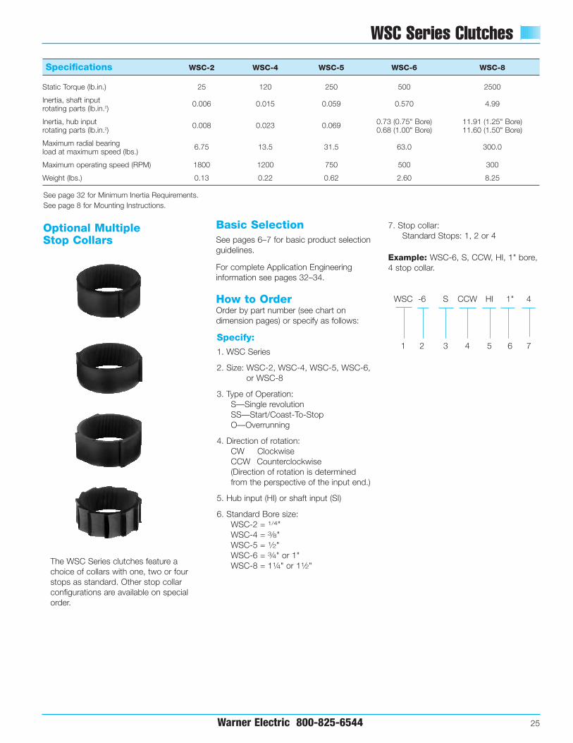
Specify:
1. WSC Series
2. Size: WSC-2, WSC-4, WSC-5, WSC-6,or WSC-8
3. Type of Operation: S—Single revolutionSS—Start/Coast-To-StopO—Overrunning
4. Direction of rotation:CW ClockwiseCCW Counterclockwise(Direction of rotation is determinedfrom the perspective of the input end.)
5. Hub input (HI) or shaft input (SI)
6. Standard Bore size:WSC-2 = 1/4"WSC-4 = 3⁄8"WSC-5 = 1⁄2"WSC-6 = 3⁄4" or 1"WSC-8 = 11⁄4" or 11⁄2"
7. Stop collar:Standard Stops: 1, 2 or 4
Example: WSC-6, S, CCW, HI, 1" bore,4 stop collar.
How to OrderOrder by part number (see chart ondimension pages) or specify as follows:
Basic SelectionSee pages 6–7 for basic product selectionguidelines.
For complete Application Engineeringinformation see pages 32–34.
Specifications WSC-2 WSC-4 WSC-5 WSC-6 WSC-8
Static Torque (lb.in.) 25 120 250 500 2500
Inertia, shaft input 0.006 0.015 0.059 0.570 4.99rotating parts (lb.in.2)
Inertia, hub input 0.008 0.023 0.069 0.73 (0.75" Bore) 11.91 (1.25" Bore)rotating parts (lb.in.2) 0.68 (1.00" Bore) 11.60 (1.50" Bore)
Maximum radial bearing 6.75 13.5 31.5 63.0 300.0load at maximum speed (lbs.)
Maximum operating speed (RPM) 1800 1200 750 500 300
Weight (lbs.) 0.13 0.22 0.62 2.60 8.25
See page 32 for Minimum Inertia Requirements.See page 8 for Mounting Instructions.
The WSC Series clutches feature achoice of collars with one, two or fourstops as standard. Other stop collarconfigurations are available on specialorder.
Optional Multiple Stop Collars
WSC -6 S CCW HI 1" 4
1 2 3 4 5 6 7

WSC-2, WSC-4, WSC-5 Clutches
26 Warner Electric 800-825-6544
Dimensions (mm)
Model PSI 2,4,5.AI5
1.25(31.75)
.94(23.9)
A.94
(23.9)
.33 (8.4).25 (6.35) .16
(4.1).57 (14.79)
1.00 (25.4)
M
.49(12.4)
.34(8.6)
.38(9.65)
.8765-.8775(22.639-22.289)
Model PSI 2,4,5.AI5
1.375(34.93)
1.25(31.75)
A1.25
(31.75)
.365 (9.27).25 (6.35) .14
(3.56).72 (18.29)
1.25 (31.75)
M
.67(17.02)
.28(7.1)
.63(16.00)
1.1265-1.1275(28.639-28.613)
Model PSI 2,4,5.AI5
1.875(47.63)
1.56(39.6)
A1.56
(39.6)
.375 (9.525).25 (6.35) .24
(6.096).85 (21.59)
1.56 (39.62)
M
1.00(25.4)
.38(9.7)
.78(19.81)
1.502-1.503(38.15-38.18)
WSC-2
WSC-4
WSC-5
WSC-2, WSC-4, WSC-5 Clutches
Warner Electric 800-825-6544 27
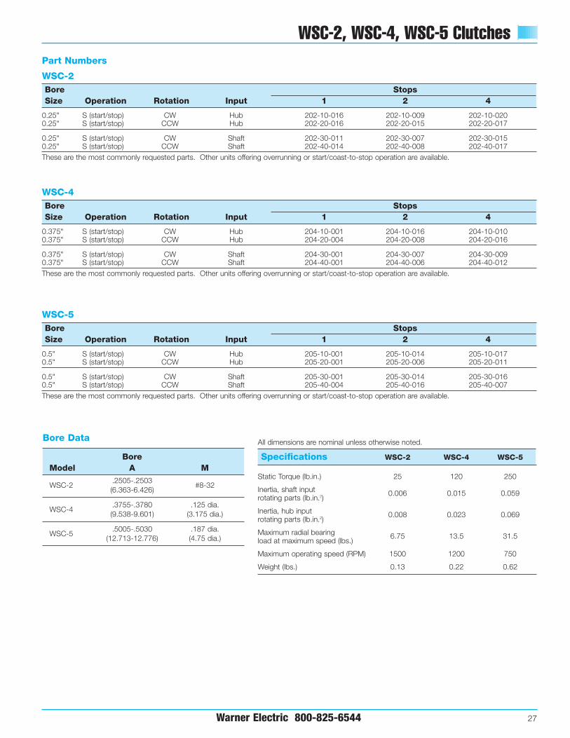
Bore Data
BoreModel A M
.2505-.2503WSC-2
(6.363-6.426)#8-32
.3755-.3780 .125 dia.WSC-4
(9.538-9.601) (3.175 dia.)
.5005-.5030 .187 dia.WSC-5
(12.713-12.776) (4.75 dia.)
Specifications WSC-2 WSC-4 WSC-5
Static Torque (lb.in.) 25 120 250
Inertia, shaft input 0.006 0.015 0.059rotating parts (lb.in.2)
Inertia, hub input 0.008 0.023 0.069rotating parts (lb.in.2)
Maximum radial bearing 6.75 13.5 31.5load at maximum speed (lbs.)
Maximum operating speed (RPM) 1500 1200 750
Weight (lbs.) 0.13 0.22 0.62
All dimensions are nominal unless otherwise noted.
WSC-2 Bore StopsSize Operation Rotation Input 1 2 4
0.25" S (start/stop) CW Hub 202-10-016 202-10-009 202-10-0200.25" S (start/stop) CCW Hub 202-20-016 202-20-015 202-20-017
0.25" S (start/stop) CW Shaft 202-30-011 202-30-007 202-30-0150.25" S (start/stop) CCW Shaft 202-40-014 202-40-008 202-40-017These are the most commonly requested parts. Other units offering overrunning or start/coast-to-stop operation are available.
WSC-4 Bore StopsSize Operation Rotation Input 1 2 4
0.375" S (start/stop) CW Hub 204-10-001 204-10-016 204-10-0100.375" S (start/stop) CCW Hub 204-20-004 204-20-008 204-20-016
0.375" S (start/stop) CW Shaft 204-30-001 204-30-007 204-30-0090.375" S (start/stop) CCW Shaft 204-40-001 204-40-006 204-40-012These are the most commonly requested parts. Other units offering overrunning or start/coast-to-stop operation are available.
WSC-5 Bore StopsSize Operation Rotation Input 1 2 4
0.5" S (start/stop) CW Hub 205-10-001 205-10-014 205-10-0170.5" S (start/stop) CCW Hub 205-20-001 205-20-006 205-20-011
0.5" S (start/stop) CW Shaft 205-30-001 205-30-014 205-30-0160.5" S (start/stop) CCW Shaft 205-40-004 205-40-016 205-40-007These are the most commonly requested parts. Other units offering overrunning or start/coast-to-stop operation are available.
Part Numbers

WSC-6, WSC-8 Clutches
28 Warner Electric 800-825-6544
.774 (19.66)
.124 (3.15)
2.311 (58.70).866
(22.00).280 (7.11).671 (17.04)
M
1.559-1.562(39.60-39.67)
2.437(61.90)
2.696(68.48)
1.500(38.10)
.286 (7.26)
Q
+
++
+
++ 3.75(95.25)
2.00(50.8)
Q
1.98(50.3)
M
3.5(88.9)
.30(7.62)
.522 (13.26) .18(4.57)
4.00(101.6)
2.374-2.376(60.300-60.350)
WSC-6
WSC-8
Bore & Keyway Data All dimensions are nominal unless otherwise noted.
Bore Keyway KeywayModel A Width B Height C M Q
.7505-.7525 .1885 .09375 3x #1/4-20 Tap on 2.062 (52.375) BCWSC-6
(19.063-19.114) (4.788) (2.381)#1/4-20 Tap
Max. Thread Engagement .310 (7.87)
1.0005-1.0025 3x #1/4-20 Tap on 2.062 (52.375) BCWSC-6
(25.412-25.464)— — #1/4-20 Tap
Max. Thread Engagement .310 (7.87)
1.2505-1.2530 .3125 .15625 3/16-16 6x 5/16-18 on 3.375 (85.725) BCWSC-8
(31.762-31.814) (7.9375) (3.9688) Max. Thread Engagement .375 (9.53)
1.5005-1.5030 .375 .125 3/16-16 6x 5/16-18 on 3.375 (85.725) BCWSC-8
(38.113-38.176) (9.525) (3.175) Max. Thread Engagement .375 (9.53)
BORE DETAIL
C
B
A

WSC-6, WSC-8 Clutches
Warner Electric 800-825-6544 29
Specifications WSC-6 WSC-8
Static Torque (lb.in.) 500 2500
Inertia, shaft input 0.570 4.99rotating parts (lb.in.2)
Inertia, hub input 0.73 (0.75" Bore) 11.91 (1.25" Bore)rotating parts (lb.in.2) 0.68 (1.00" Bore) 11.60 (1.50" Bore)
Maximum radial bearing 63 300load at maximum speed (lbs.)
Maximum operating speed (RPM) 500 300
Weight (lbs.) 2.60 8.25
WSC-6 Bore StopsSize Operation Rotation Input 1 2 4
0.75" S (start/stop) CW Hub 206-10-002 206-10-062 206-10-0640.75" S (start/stop) CCW Hub 206-20-002 206-20-023 206-20-058
0.75" S (start/stop) CW Shaft 206-30-011 206-30-052 206-30-0250.75" S (start/stop) CCW Shaft 206-40-002 206-40-014 206-40-020
1.0" S (start/stop) CW Hub 206-10-003 206-10-057 206-10-0591.0" S (start/stop) CCW Hub 206-20-003 206-20-060 206-20-013
1.0" S (start/stop) CW Shaft 206-30-003 206-30-051 206-30-0561.0" S (start/stop) CCW Shaft 206-40-013 206-40-023 206-40-025These are the most commonly requested parts. Other units offering overrunning or start/coast-to-stop operation are available.
WSC-8 Bore StopsSize Operation Rotation Input 1 2 4
1.25" S (start/stop) CW Hub 208-10-004 208-10-027 208-10-0281.25" S (start/stop) CCW Hub 208-20-001 208-20-028 208-20-030
1.25" S (start/stop) CW Shaft 208-30-001 208-30-021 —1.25" S (start/stop) CCW Shaft 208-40-013 208-40-015 208-40-017
1.50" S (start/stop) CW Hub 208-10-007 208-10-025 208-10-0301.50" S (start/stop) CCW Hub 208-20-003 208-20-032 208-20-021
1.50" S (start/stop) CW Shaft 208-30-003 208-30-025 208-30-0271.50" S (start/stop) CCW Shaft 208-40-003 208-40-020 208-40-022These are the most commonly requested parts. Other units offering overrunning or start/coast-to-stop operation are available.
Part Numbers
Power Supply Units
30 Warner Electric 800-825-6544
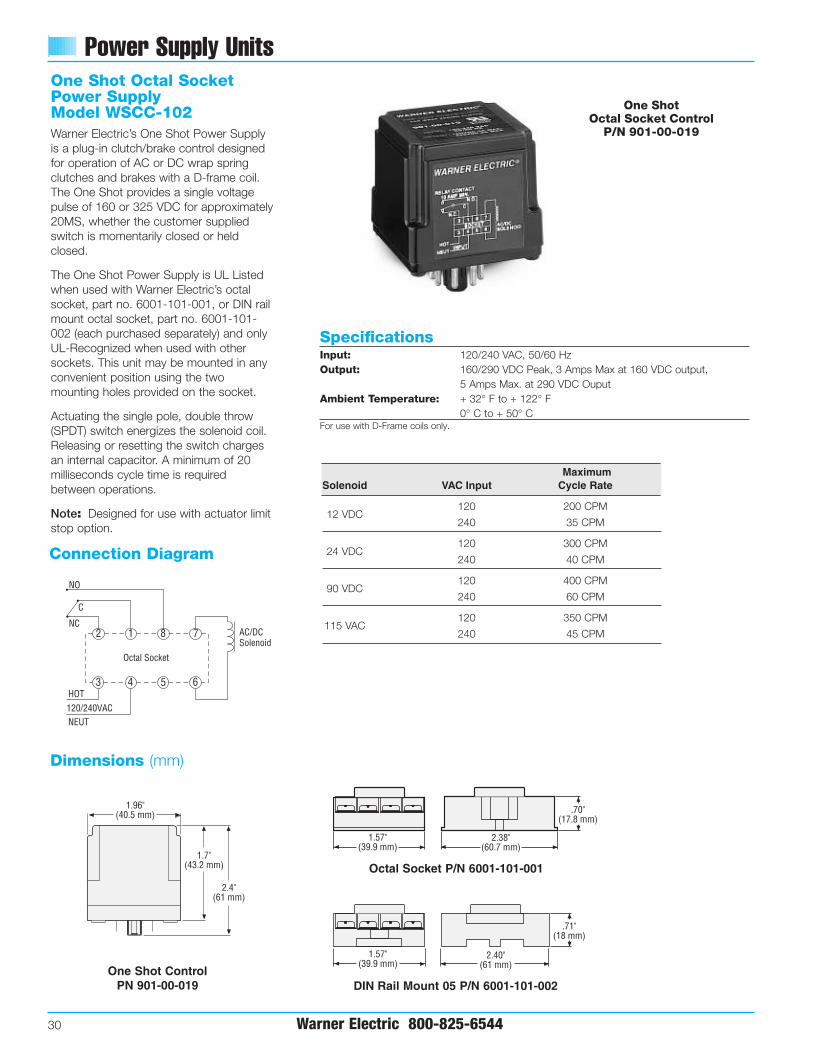
SpecificationsInput: 120/240 VAC, 50/60 HzOutput: 160/290 VDC Peak, 3 Amps Max at 160 VDC output,
5 Amps Max. at 290 VDC OuputAmbient Temperature: + 32° F to + 122° F
0° C to + 50° CFor use with D-Frame coils only.
One Shot Octal SocketPower SupplyModel WSCC-102Warner Electric’s One Shot Power Supplyis a plug-in clutch/brake control designedfor operation of AC or DC wrap springclutches and brakes with a D-frame coil.The One Shot provides a single voltagepulse of 160 or 325 VDC for approximately20MS, whether the customer suppliedswitch is momentarily closed or heldclosed.
The One Shot Power Supply is UL Listedwhen used with Warner Electric’s octalsocket, part no. 6001-101-001, or DIN railmount octal socket, part no. 6001-101-002 (each purchased separately) and onlyUL-Recognized when used with othersockets. This unit may be mounted in anyconvenient position using the twomounting holes provided on the socket.
Actuating the single pole, double throw(SPDT) switch energizes the solenoid coil.Releasing or resetting the switch chargesan internal capacitor. A minimum of 20milliseconds cycle time is requiredbetween operations.
Note:: Designed for use with actuator limitstop option.
Dimensions (mm)
Connection Diagram
Octal Socket P/N 6001-101-001
One Shot ControlPN 901-00-019 DIN Rail Mount 05 P/N 6001-101-002
One Shot Octal Socket Control
P/N 901-00-019
1
4 5
8
6
7
3
2
Octal Socket
NO
NC
C
HOT
NEUT120/240VAC
AC/DCSolenoid
Connect Diagram.AI5
1.96"(40.5 mm)
1.7"(43.2 mm)
2.4"(61 mm)
1.57"(39.9 mm)
2.38"(60.7 mm)
.70"(17.8 mm)
1.57"(39.9 mm)
2.40"(61 mm)
.71"(18 mm)
1 Shot Controls Dim.AL5
1.96"(40.5 mm)
1.7"(43.2 mm)
2.4"(61 mm)
1.57"(39.9 mm)
2.38"(60.7 mm)
.70"(17.8 mm)
1.57"(39.9 mm)
2.40"(61 mm)
.71"(18 mm)
1 Shot Controls Dim.AL5
1.96"(40.5 mm)
1.7"(43.2 mm)
2.4"(61 mm)
1.57"(39.9 mm)
2.38"(60.7 mm)
.70"(17.8 mm)
1.57"(39.9 mm)
2.40"(61 mm)
.71"(18 mm)
1 Shot Controls Dim.AL5
MaximumSolenoid VAC Input Cycle Rate
12 VDC120 200 CPM
240 35 CPM
24 VDC120 300 CPM
240 40 CPM
90 VDC120 400 CPM
240 60 CPM
115 VAC120 350 CPM
240 45 CPM
Power Supply Units
Warner Electric 800-825-6544 31
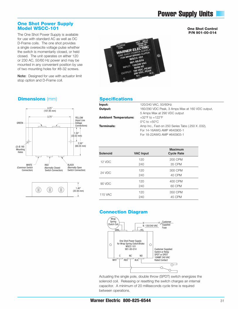
One Shot Power SupplyModel WSCC-101The One Shot Power Supply is availablefor use with standard AC as well as DC D-Frame coils. The one shot provides a single overexcite voltage pulse whetherthe switch is momentarily closed, or heldclosed. The unit operates on either 120 or 230 AC, 50/60 Hz power and may bemounted in any convenient position by useof two mounting holes for #8-32 screws.
Note: Designed for use with actuator limitstop option and D-Frame coil.
Dimensions (mm) Specifications
Actuating the single pole, double throw (SPDT) switch energizes thesolenoid coil. Releasing or resetting the switch charges an internalcapacitor. A minimum of 20 milliseconds cycle time is requiredbetween operations.
MountingHoles
(2) Ø.190
3.75"
4.25"(107.95 mm)
1.30"(33.02 mm)
2.50"(66.04 mm)
GREEN
WHITE (Common Switch
Connection)
YELLOW(Input Line Voltage Connections)
RED(Normally ClosedSwitch Connection)
BLACK(Normally Open Switch Connection)
1.40"(35.56 mm)
Connection Diagram
NC NOC
Wrap Spring
Clutch Coil 120/240 VACHN
One Shot Power Supply for Wrap Spring Clutch/Brake
WSCC-101901-00-014
YELGRN
WHT RED BLK
Customer Supplied Switch or RelaySPDT or DPDT10AMP 240 VACRated Contact
Customer Supplied Fuse
One Shot ControlP/N 901-00-014
Input: 120/240 VAC, 50/60HzOutput: 160/290 VDC Peak, 3 Amps Max at 160 VDC output,
5 Amps Max at 290 VDC outputAmbient Temperature: +32°F to +122°F
0°C to +50°CTerminals: Amp Inc., Fast-on 250 Series Tabs (.250 X .032),
For 14-16AWG AMP #640905-1For 18-22AWG AMP #640903-1
MaximumSolenoid VAC Input Cycle Rate
12 VDC120 200 CPM
240 35 CPM
24 VDC120 300 CPM
240 40 CPM
90 VDC120 400 CPM
240 60 CPM
115 VAC120 350 CPM
240 45 CPM

Application Engineering
32 Warner Electric 800-825-6544
Selection Considerations
Application Analysis
1. FunctionThe process for establishing the clutch or brake function is illustrated in Step 1 on page 4. In review, the three functions and the appropriate series selections are noted below.
Overrunning (One Way Clutch)Unidirectional torque transmission with free wheeling in opposite direction.
SelectionWSC (Model O)
Start/Coast-to-Stop (Random Positioning)Engage/disengage with random stop position.
SelectionWSC (Model SS)
Start/Stop (Single Revolution)Accurate stop position in single or fraction revolution cycles.
SelectionWSC (Model S)Standard CBSuper CB
2. Calculate load inertia (WR2)Use the inertia chart on page 33 to determine the inertia of the application components. To determine WR2 of a given shaft or disc, multiply the WR2
from the chart by the length of shaft or thickness of disc in inches. Note: For hollow shafts, subtract WR2 of the I.D. from the WR2 of the O.D. and multiply by length.
In order to calculate the inertias of components which are made of material other than steel, use the multipliers found in the conversion chart (right) to establish the inertias of these components.
For applications involving machined parts or reflected rotational or linear inertia, please refer to the inertia discussion in the Application Engineering section of Warner Electric’s Packaged Electromagnetic Clutches/Brakes Catalog, P-1234.
Inertia Conversion ChartIn order to determine the inertia of arotating member (shaft, disc, etc.) of amaterial other than steel, multiply theinertia of the appropriate steel diameterfrom the chart on page 33 by:
Material Multiplier
Bronze 1.05
Steel 1.00
Iron .92
Powdered Metal Bronze .79
Powdered Metal Iron .88
Aluminum .35
Nylon .17
25
50
100
150
200
250
500
750
1000
1250
1500
2000
2500
5000T
orq
ue
(lb
. in
s.)
2 4 5 6 8
CB Series & Super CB SeriesSingle Revolution
2 4 5 6 8
WSC SeriesOverrunning –Start/Stop
Series and Model
Torque vs. Model Comparison

Application Engineering
Warner Electric 800-825-6544 33
Selection Considerations
Inertia of Steel Shafting (Per Inch of Length or Thickness)
Dia. WR2
(in.) (lb.in.2 )
1⁄4 .000113⁄8 .000551⁄2 .001733⁄4 .008641 .028811⁄4 .07211⁄2 .14413⁄4 .2882 .43221⁄4 .7221⁄2 1.15223⁄4 1.5843 2.30431⁄2 4.17633⁄4 5.4724 7.05641⁄4 9.07241⁄2 11.3765 17.2851⁄2 25.4886 3661⁄4 42.62461⁄2 49.6863⁄4 57.888
Dia. WR2
(in.) (lb.in.2 )
7 66.81671⁄4 77.0471⁄2 87.98473⁄4 100.6568 113.90481⁄4 128.8881⁄2 14483⁄4 162.729 182.8891⁄4 203.0491⁄2 223.293⁄4 25210 277.92101⁄4 306.72101⁄2 338.4103⁄4 371.5211 407.52111⁄4 444.96111⁄2 486.72113⁄4 529.9212 576121⁄4 626.4121⁄2 679.68123⁄4 735.84
Dia. WR2
(in.) (lb.in.2 )
13 803.52131⁄4 858.24131⁄2 924.48133⁄4 995.0414 1068.48141⁄4 1147.68141⁄2 1229.75143⁄4 1317.615 140416 1815.8417 2314.0818 2910.2419 3611.5220 4433.7621 5389.9222 6492.9623 7757.2824 9195.8425 10827.3626 12666.2427 14731.228 17036.6429 19604.1630 22452.48
Model Tc t Ic
CB-2 1.65 0.003 0.0116
CB-4 6.60 0.004 0.0450
CB-5 6.88 0.004 0.1663
CB-6 8.75 0.005 1.221 (0.75 in. bore)1.138 (1.0 in. bore)9.43 (0.75 in. bore)
CB-8 20 0.005 9.32 (1.0 in. bore)8.15 (1.5 in. bore)
TToorrqquuee && IInneerrttiiaa VVaalluueess

Application EngineeringSelection Considerations
34 Warner Electric 800-825-6544
3. Determine clutch orbrake torque value
With the inertia value calculated in Step2, determine the torque requirement forthe function determined in Step 1.
A) For Overrunning and Start-Stop(random start-stop)(WSC Models SS and O)
T = WR2 x RPM + friction torque 3700 x t
Where—T = Torque required from wrap springWR2 = load inertia (Step 2)RPM = shaft speed at clutch locationt = time to engagement (.003 for clutch)
B) For single revolution applications (CB and WSC ModelS)
T = WR2 x RPM – friction torque*3700 x t
Where—
T = torque required from wrap springWR2 = Load inertia (Step 2)RPM = Shaft speed at clutch or brake
locationt = time to disengagement
(.0015 for brake)
Find the value of T on the Torque vs.Model Comparison Chart on page 32.
*Frictional (drag) torque is the torque necessaryto overcome static friction. It may be measuredby a spring-scale or by dead-weights, applied toa known moment arm so gradually as to makeinertia negligible. It is that torque found justsufficient to induce motion.
4. Verify selection with unit inertia
From the individual productspecifications find the unit inertia of themodel selected in Step 3. Add this to theload inertia previously determined toarrive at the total torque requirement.
A) For Overrunning and On-Off(WSC Models SS and O)
A) Tt = (WR2LOAD + WR2
UNIT)RPM
3700 x t
B) For Single Revolution Start-Stop(CB, Super CB and WSC ModelS)
B) Tt = (WR2LOAD + WR2
UNIT)RPM
3700 x t
Where–Tt = total system torque(WR2
LOAD) = load inertia (WR2
UNIT) = clutch inertia
Find this new torque value on the Torquevs. Model Comparison Charton page 32 to verify the model selectedin Step 3.
Minimum Load Inertia—Super CB and CB Clutch/Brakes In order to achieve the CB accuracycapability of ±1/2°, a minimum loadinertia is required to fully engage thebrake spring and disengage the clutchspring. This minimum inertia ( l ) can becalculated from the accompanyingformula and chart:
l = (t) (Tc + To) (3700) – IcRPMl = Minimum inertia required to fully
activate the clutch/brake—lb.in.2
t = Time—SecondsTc = Torque required to fully activate
the clutch/brake—in.lb.To = Drag torque—in.lb.RPM = Revolutions per minuteIc = Inertia at the output side of the
clutch—lb.in.2
EXAMPLE: CB-6 in a system running at200 RPM with 3⁄4" bore and 20 in.lb.drag. What inertia is required to fullyactivate the clutch/brake?
I = (0.005) (8.75 + 20) (3700) – 1.221 = 1.438 lb.in.2
(200)
NOTE: When calculated inertia is zero ornegative, no further action is required. Ifthe calculation result is positive,additional inertia equal to or exceedingthe result should be added.
How to determine maximum inertiaload of CBs
T x 3700 x t = WR2
RPMT = Clutch Torquet = .0015
+ friction torque
– friction torque

Part Numbers
Warner Electric 800-825-6544 35
Bore StopsSize Voltage Rotation 1 2 4
CB-2 0.25" 24 VDC CW 302-17-001 • 302-17-002 • 302-17-003
CCW 302-27-001 302-27-011 302-27-003
0.25" 115 VAC CW • 302-17-007 302-17-008 302-17-009CCW 302-27-007 302-27-008 302-27-009
CB-40.375" 24 VDC CW • 304-17-001 • 304-17-011 304-17-007
CCW • 304-27-001 • 304-27-007 304-27-026
0.375" 115 VAC CW • 304-17-003 • 304-17-008 • 304-17-018CCW • 304-27-003 304-27-015 • 304-27-025
CB-50.5" 24 VDC CW • 305-17-001 • 305-17-002 305-17-003
CCW • 305-27-001 305-27-002 305-27-003
0.5" 115 VAC CW • 305-17-007 305-17-008 305-17-009CCW • 305-27-007 • 305-27-008 • 305-27-009
CB-60.75" 24 VDC CW • 306-17-051 • 306-17-074 306-17-162
CCW • 306-27-029 • 306-27-046 • 306-27-134
0.75" 115 VAC CW • 306-17-053 • 306-17-060 • 306-17-073CCW • 306-27-031 • 306-27-039 • 306-27-045
1.0" 24 VDC CW • 306-17-057 306-17-061 306-17-031CCW • 306-27-032 306-27-147 306-27-150
1.0" 115 VAC CW • 306-17-059 306-17-062 306-17-075 CCW • 306-27-034 • 306-27-044 • 306-27-037
CB-81.25" 24 VDC CW • 308-17-101 • 308-17-102 308-17-103
CCW • 308-27-101 308-27-102 308-27-103
1.25" 115 VAC CW • 308-17-107 308-17-108 308-17-109CCW • 308-27-107 • 308-27-108 308-27-109
1.5" 24 VDC CW • 308-17-119 308-17-120 308-17-121CCW 308-27-119 308-27-120 308-27-121
1.5" 115 VAC CW • 308-17-125 • 308-17-126 308-17-127CCW • 308-27-125 308-27-126 308-27-127
SCB-50.5" 24 VDC CW • 325-17-001 325-17-002 325-17-003
CCW 325-27-001 325-27-002 325-27-003
0.5" 115 VAC CW • 325-17-004 325-17-005 325-17-006CCW • 325-27-004 325-27-005 325-27-006
SCB-60.75" 24 VDC CW • 326-17-007 • 326-17-008 326-17-009
CCW • 326-27-007 326-27-008 326-27-009
0.75" 115 VAC CW • 326-17-019 • 326-17-020 326-17-021CCW • 326-27-019 • 326-27-020 326-27-021
1.0" 24 VDC CW • 326-17-010 326-17-011 • 326-17-012CCW • 326-27-010 326-27-011 • 326-27-012
1.0" 115 VAC CW • 326-17-022 326-17-023 326-17-024CCW • 326-27-022 326-27-023 326-27-024
Bore StopsSize Voltage Rotation Input 1 2 4
SCB-81.25" 24 VDC CW • 328-17-019 •328-17-020 328-17-021
CCW • 328-27-019 328-27-020 328-27-021
1.25" 115 VAC CW • 328-17-043 328-17-044 328-17-045CCW • 328-27-043 • 328-27-044 328-27-045
1.5" 24 VDC CW • 328-17-013 328-17-014 328-17-015CCW 328-27-013 328-27-014 328-27-015
1.5" 115 VAC CW 328-17-037 328-17-038 328-17-039CCW 328-27-037 328-27-038 328-27-039
WSC-2 0.25" S CW Hub 202-10-016 202-10-009 202-10-0200.25" S CCW Hub 202-20-016 202-20-015 202-20-017
0.25" S CW Shaft 202-30-011 202-30-007 202-30-0150.25" S CCW Shaft 202-40-014 202-40-008 202-40-017
WSC-4 0.375" S CW Hub 204-10-001 204-10-016 204-10-0100.375" S CCW Hub 204-20-004 204-20-008 204-20-016
0.375" S CW Shaft 204-30-001 204-30-007 204-30-0090.375" S CCW Shaft 204-40-001 204-40-006 204-40-012
WSC-5 0.5" S CW Hub 205-10-001 205-10-014 205-10-0170.5" S CCW Hub 205-20-001 205-20-006 205-20-011
0.5" S CW Shaft 205-30-001 205-30-014 205-30-0160.5" S CCW Shaft 205-40-004 205-40-007 205-40-016
WSC-6 0.75" S CW Hub 206-10-002 206-10-062 206-10-0640.75" S CCW Hub 206-20-002 206-20-023 206-20-058
0.75" S CW Shaft 206-30-011 206-30-052 206-30-0250.75" S CCW Shaft 206-40-002 206-40-014 206-40-020
1.0" S CW Hub 206-10-003 206-10-057 206-10-0591.0" S CCW Hub 206-20-003 206-20-060 206-20-013
1.0" S CW Shaft 206-30-003 206-30-051 206-30-0561.0" S CCW Shaft 206-40-013 206-40-023 206-40-025
WSC-8 1.25" S CW Hub 208-10-004 208-10-027 208-10-0281.25" S CCW Hub 208-20-001 208-20-028 208-20-030
1.25" S CW Shaft 208-30-001 208-30-021 —1.25" S CCW Shaft 208-40-013 208-40-015 208-40-017
1.50" S CW Hub 208-10-007 208-10-025 208-10-0301.50" S CCW Hub 208-20-003 208-20-032 208-20-021
1.50" S CW Shaft 208-30-003 208-30-025 208-30-0271.50" S CCW Shaft 208-40-003 208-40-020 208-40-022
For CB and SCB Series units, these are the most commonly requested parts –other voltages (such as 12VDC and 90VDC), bores and stop collars areavailable.
For the WSC Series, other units offering different bores, and overrunning orstart/coast-to-stop operation are available.
• Denotes stock items shipped FOB Roscoe or South Beloit, Illinois
Part Numbers Part Numbers
Control Part #’sOne Shot, 150 Ohms • 901-00-014One Shot, Octal Socket • 901-00-019

Application Data Form
36 Warner Electric 800-825-6544
MMaaiill oorr FFaaxx ttoo::
WWaarrnneerr EElleeccttrriiccTechnical Support449 Gardner Street, South Beloit, Illinois 61080Phone 815-389-6224 • Fax 815-389-6678 • www.warnerelectric.comEmail: [email protected]
AAccttuuaattiioonnMechanical ( )Electrical ( )Voltage AC
DC
MMoottiioonnSingle Revolution ( )Fractional Revolution ( )Angle ( )
AAccccuurraaccyyStart ( ms )Stop ( ±__° )
SShhaafftt DDiiaammeetteerrMinimum ( ")Maximum ( ")
TTeecchhnniiccaall DDaattaaSpeed___________________________( rpm )
Inertia ___________________________( lb.in.2 )
Friction Load Torque ______________( lb.in. )
Cycle Rate _________________ ( per second )
Life Expectancy _____________ ( hrs or cycles )
EEnnvviirroonnmmeennttaall CCoonnssiiddeerraattiioonn
____________________________________________________________________________
____________________________________________________________________________
____________________________________________________________________________
____________________________________________________________________________
____________________________________________________________________________
Describe the application function
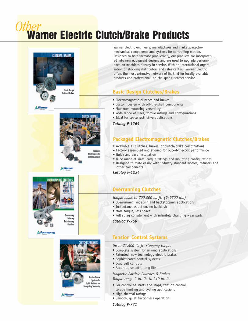
OtherWarner Electric Clutch/Brake Products
Basic Design Clutches/Brakes• Electromagnetic clutches and brakes• Custom design with off-the-shelf components• Maximum mounting versatility• Wide range of sizes, torque ratings and configurations• Ideal for space restrictive applications
Catalog P-1264
Tension Control SystemsUp to 21,500 lb. ft. stopping torque• Complete system for unwind applications• Patented, new technology electric brakes• Sophisticated control systems• Load cell controls• Accurate, smooth, long life
Magnetic Particle Clutches & BrakesTorque range 2 in. lb. to 240 in. lb.
• For controlled starts and stops, tension control, torque limiting and cycling applications
• High thermal ratings• Smooth, quiet frictionless operation
Catalog P-771
Overrunning ClutchesTorque loads to 700,000 lb. ft. (949200 Nm)• Overrunning, indexing and backstopping applications• Instantaneous action, no backlash• More torque, less space• Full sprag complement with infinitely changing wear parts
Catalog P-956
Warner Electric engineers, manufactures and markets, electro-mechanical components and systems for controlling motion.Designed to help increase productivity, our products are incorporat-ed into new equipment designs and are used to upgrade perform-ance on machines already in service. With an international organi-zation of stocking distributors and sales centers, Warner Electricoffers the most extensive network of its kind for locally availableproducts and professional, on-the-spot customer service.
Packaged Electromagnetic Clutches/Brakes• Available as clutches, brakes, or clutch/brake combinations• Factory assembled and aligned for out-of-the-box performance• Quick and easy installation• Wide range of sizes, torque ratings and mounting configurations• Designed to mate easily with industry standard motors, reducers and
other componentsCatalog P-1234
w w w . w a r n e r e l e c t r i c . c o m
Printed in USA
Warner Electric, Inc.449 Gardner Street • South Beloit, IL 61080815-389-3771 • Fax: 815-389-2582www.warnerelectric.com
P-1310 7/03*
Warner ElectricElectromagnetic Clutches and Brakes - USA
South Beloit, IL 61080815-389-3771
For application assistance:1-800-825-9050
Electromagnetic Clutches and Brakes - Europe
St Barthelemy d’Anjou, France+33 (0)2 41 21 24 24
For sales office:+33 (0)2 41 21 24 76
Precision Electric Coils andElectromagnetic Clutches and Brakes - USA
Columbia City, IN 46725260-244-6183
Inertia Dynamics Spring Set Brakes; Power On andWrap Spring Clutch/Brakes
Torrington, CT 06790860-482-4444
Matrix InternationalElectromagnetic Clutches and Brakes, Pressure Operated Clutches and Brakes
Brechin, Scotland+44 (0) 1356 602000
Warner LinearLinear Actuators and Guideways - USA
Belvidere, IL 61008815-547-1106
For application assistance:1-800-825-9050
Boston GearEnclosed and Open Gearing, Electrical and Mechanical P.T. Components, Precision Gearheads, Precision Couplings
Quincy, MA 02171617-328-3300
For customer service:1-888-999-9860
For application assistance:1-800-816-5608
Huco DynatorkPrecision Couplings and Air Motors
Hertford, England+44 (0) 1992 501900
Formsprag Clutch
Overrunning Clutches and Holdbacks
Warren, MI 48089586-758-5000
For application assistance:1-800-927-3262
Marland ClutchRoller Ramp and Sprag Type Overrunning Clutches and Backstops
Burr Ridge, IL 60527630-455-1752
Stieber Clutch Overrunning Clutches and Holdbacks
Heidelberg, Germany+49 (0)6221 30 47 0
Wichita Clutch and Industrial ClutchPneumatic and Oil ImmersedClutches and Brakes - USA
Wichita Falls, TX 76302940-723-3400
Pneumatic Clutches and Brakes - Europe
Bedford, England+44 (0)1234 350311
Twiflex LimitedCaliper Brakes and Thrusters
Twickenham, England+44 (0) 20 8894 1161
Ameridrives CouplingsGear Couplings, Mill Spindles,Universal Joints
Erie, PA 16512814-480-5000
Bibby TransmissionsDisc, Gear, Grid Couplings, Overload Clutches
Dewsbury, England+44 (0) 1924 460801
Nuttall Gear andDelroyd Worm GearWorm Gear and Helical Speed Reducers
Niagara Falls, NY 14302716-298-4100
Saftek FrictionNon-asbestos Brake and ClutchMaterials
Telford, England+44 (0) 1952 581122
Altra Industrial Motion -Asia Pacific and Africa
China 852 2615 9313
Taiwan 886 2 2577 8156
Singapore 65 487 4464
Thailand 66 2 322 0481
Australia 612 9894 0133
S. Africa 27 11 918 4270