WP004-E-0615 Sewage plants - Process Solutions€¦ · The complete process control system of the...
24
Retrofitting sewage plants with lightning and surge protection measures White Paper www.dehn-international.com Contents Assessment of the risk for the operations building Plant description Lightning protection zone concept Lightning protection system Lightning equipotential bonding for all conductive systems entering the sewage plant Equipotential bonding Surge protection for the low- voltage power supply system Surge protection for information technology systems
Transcript of WP004-E-0615 Sewage plants - Process Solutions€¦ · The complete process control system of the...

Retrofitting sewage plants with lightning and surge protection measuresWhite Paper
www.dehn-international.com
Contents
Assessment of the risk for the operations building
Plant description
Lightning protection zone concept
Lightning protection system
Lightning equipotential bonding for all conductive systems entering the sewage plant
Equipotential bonding
Surge protection for the low-voltage power supply system
Surge protection for information technology systems

2
Retrofitting sewage plants with lightning and surge protection measuresWhite Paper
WP004/E/0615 © Copyright 2015 DEHN + SÖHNE
Figure 1 Schematic diagram of a sewage plant
rainwater overflow basin pump / lift stationcoarse / fine screen
black water basin
operations building
ventilator / sand filter and grease trap
primary clarifier
precipitant tank
aeration tank / nitrification – denitrification
final clarifier
effluent
river
A more efficient use of drinking water is growing in significance, especially against a backdrop of increasingly scarce drinking water resources. Therefore, sewage plants are a key element of the drinking water cycle. The necessary high efficiency of sew-age plants (Figure 1) requires that the operating procedure be optimised and the operating costs be reduced at the same time. For this purpose, high investments were made in electronic measuring equipment and distributed electronic control and automation systems over the last years. However, these new electronic systems only provide a low resistance to transients compared to conventional technology. The structural conditions of the widespread outdoor wastewater treatment systems with measuring equipment and control units extending over large ar-eas additionally increase the risk of interference caused by light-ning discharges or surges. Thus, it is most likely that the com-plete process control system or parts thereof fail if no protection measures are taken. The consequences of such a failure can be serious ranging from costs for re-establishing the availability of the sewage plant to the unknown costs for eliminating ground water contamination. Consequently, external and internal light-ning protection measures must be taken to efficiently eliminate this threat and to increase the availability of the systems.
Assessment of the risk for the operations building The example described in the following was calculated based on the IEC 62305-2 (EN 62305-2) standard. We expressively point out that the procedure shown is only an example. This
solution is not binding in any way and can be substituted by other equivalent solutions. In the following, only the essential characteristics of the example will be shown. At first, a ques-tionnaire with important questions on the structure and its use was discussed and filled in together with the operator. This procedure allows to prepare a lightning protection concept that is comprehensible for all parties involved. The concept includes the minimum requirements which, however, can be technically improved at any time.
Plant descriptionThe complete process control system of the sewage plant is centrally located in the operations building. In case of a light-ning strike, substantial partial lightning currents and surges are injected into the switch rooms via the extended cables leading to measuring stations and substations. In the past, this caused destruction and failure of the plant over and over again. The same applies to the power supply and telephone line. The operations building itself must be protected against damage resulting from fire (caused by a direct lightning strike) and the electrical and electronic systems (control and automa-tion system, telecontrol system) from the effects of the light-ning electromagnetic pulse (LEMP).
Additional conditions:
¨ Protection measures against lightning effects have already been taken (external lightning protection system accord-

3WP004/E/0615 © Copyright 2015 DEHN + SÖHNE
Retrofitting sewage plants with lightning and surge protection measuresWhite Paper
operations building
measuring pointMCE
Figure 2 Division of the operations building into lightning protection zones; example: selection of surge protective devices for the oxygen measurement device
Protection for… Type Part No.
Power supply system
TN systemDEHNguard DG M TN 275DEHNguard DG M TN 275 FM
952 200952 205
TT systemDEHNguard DG M TT 2P 275 orDEHNguard DG M TT 2P 275 FM
952 110952 115
Oxygen measure-ment device
e.g. 4 to 20 mABLITZDUCTOR BXT ML4 BE S 24 + BXT BAS base part orBLITZDUCTOR BXT ML2 BE 24 + BXT BAS base part
920 224 + 920 300920 324 + 920 300
ing to the previous IEC 62305-1 (EN 62305-1) standard, VGA 280/4 surge protective devices (SPDs) installed at the entrance point of the 230/400 V power supply line into the building, VM 280 SPDs of requirement class C installed in the switchgear cabinets of the measuring and control equipment).
¨ The following types of loss are relevant: L2: Loss of service to the public (water supply and wastewater disposal) and L4: Loss of economic value (structures and their contents). Type of damage L1: Loss of human life was excluded since the plant will be fully automated at a later date.
An assessment of the actual state shows that the calculated risk R for the types of damage L2 and L4 is still considerably higher than the tolerable risk RT.
Possible protection measures are taken to ensure R < RT for both types of damage:
¨ Installation of a lightning protection system with class of LPS III according to IEC 62305-3 (EN 62305-3) (this com-
plies with the recommendations in the German VdS pub-lication 2010).
¨ Installation of type 1 SPDs according to IEC 61643-11 (EN 61643-11) (power supply) and SPDs of category D1 according to IEC 61643-21 (EN 61643-21) for the informa-tion technology lines (measuring and control lines as well as telecommunication lines) at the zone transitions from LPZ 0A to 1.
¨ Type 2 SPDs according to IEC 61643-11 (EN 61643-11) (power supply) and surge protective devices of category C2 according to IEC 61643-21 (EN 61643-21) for the informa-tion technology lines (measuring and control lines as well as telecommunication lines) at the zone transitions from LPZ 0B to 1 and 1 to 2.
Lightning protection zone conceptTo ensure maximum technical and economic protection, the operations building is subdivided into lightning protection zones (LPZs). Subsequently, a risk analysis is carried out for each LPZ and the relevant types of damage. The mutual de-pendences of the LPZs are then examined and the required

4
Retrofitting sewage plants with lightning and surge protection measuresWhite Paper
WP004/E/0615 © Copyright 2015 DEHN + SÖHNE
protection measures are defined to reach the necessary protec-tion goal in all lightning protection zones. The following areas were subdivided into lightning protection zone 1 (LPZ 1) and lightning protection zone 2 (LPZ 2):
¨ Evaluation unit in the control room (LPZ 2)
¨ Oxygen measurement device in the aeration tank (LPZ 1)
¨ Interior of the control room (LPZ 1)
According to the lightning protection zone concept described in IEC 62305-4 (EN 62305-4), all lines at the boundaries of lightning protection zones must be protected by suitable surge protection measures.
Figure 2 exemplarily shows suitable surge protection meas-ures for the oxygen measurement device in the aeration tank. The field cables are located in LPZ 0B throughout their entire course. Therefore, type 2 SPDs can be used for protecting the oxygen measurement device and the control systems since (partial) lightning currents are not to be expected in LPZ 0B .
Lightning protection systemThe existing lightning protection system of the operations building was tested according to the requirements of class of LPS III. The indirect connection of the roof-mounted structures (air-conditioning systems) via isolating spark gaps was re-moved. Air-termination rods with the required separation dis-tances and protective angles were used to protect the sewage plant from a direct lightning strike (Figure 3). Consequently, in case of a direct lightning strike to the control room, par-tial lightning currents can no longer flow into the structure and cause damage. Due to the dimensions of the control room (15 m x 12 m), the number of down conductors (4) did not have to be changed. The local earth-termination system of the operations building was tested at all measuring points and the values were documented. Retrofitting was not required.
Lightning equipotential bonding for all conductive systems entering the sewage plantIn principle, all conductive systems entering the sewage plant must be integrated in the lightning equipotential bonding (Figure 4). This is achieved by directly connecting all metal systems and indirectly connecting all live systems via surge protective devices. Type 1 SPDs (power supply systems) and category D1 SPDs (information technology systems) must have a discharge capacity of 10/350 μs test waveform. Lightning equipotential bonding should be established as close as possi-ble to the entrance point into the structure to prevent lightning currents from entering the building.
Equipotential bondingConsistent equipotential bonding according to IEC 60364-4-41 (HD 60364-4-41), IEC 60364-5-54 (HD 60364-5-54) and IEC 62305-3 (EN 62305-3) is established in the entire opera-tions building. The existing equipotential bonding system is tested to avoid potential differences between different ex-traneous conductive parts. Supporting and structural parts of the building, pipes, containers, etc. are integrated in the equipotential bonding system so that voltage differences do not have to be expected, even in case of failure. If surge protective devices are used, the cross-section of the copper earthing conductor for equipotential bonding must be at least 16 mm2 in case of SPDs for power supply systems and at least 6 mm2 in case of SPDs for information technology systems (e.g. BLITZDUCTOR) or the cross section specified in the installation instructions must be used. Moreover, in areas with potentially explosive atmospheres the connections of the equipotential bonding conductors e.g. at equipotential bonding bars must be secured against self-loosening (e.g. by means of spring washers).
Surge protection for the low-voltage power supply systemIn the described application, the VGA 280/4 surge protec-tive device installed at the entrance point into the building is replaced by a DEHNventil M TNS 255 FM type 1 combined arrester (Figure 5) since the “old” SPD no longer fulfils the requirements for lightning protection systems according to IEC 62305-3 (EN 62305-3). The VM 280 type 2 SPDs were tested by means of a PM 10 arrester test unit. Since the test values were still within the tolerances, the SPDs did not have to be removed. If further SPDs are installed for protecting ter-minal equipment, they must be coordinated with each other and with the terminal equipment to be protected. The relevant installation instructions must be observed.
In other respects, the use of surge protective devices in the low-voltage consumer's installation does not differ from other
h [m]
α° 80
70
60
50
40
30
20
10
0 0 2 10 20 30 40 50 60
I II III IV
Figure 3 Protective angle method according to IEC 62305-3 (EN 62305-3)

5WP004/E/0615 © Copyright 2015 DEHN + SÖHNE
Retrofitting sewage plants with lightning and surge protection measuresWhite Paper
Figure 4 Lightning equipotential bonding according to DIN EN 62305-3 (VDE 0185-305-3), Supplement 1
DNO
Ex i
MEB
heater
gas
Telecontrol /telecommunication
Measuring and control equipment
PROFIBUS
external LPSfoundation earth electrode
No. in Fig. Protection for Surge protective device *floating remote signalling contact Part No.
Power supply systems
TN-C systemDEHNventil DV M TNC 255DEHNventil DV M TNC 255 FM*
951 300951 305
TN-S/TT systemDEHNventil DV M TT 255DEHNventil DV M TT 255 FM*
951 310951 315
Information technology systems
Telecontrol, telecommunicationBLITZDUCTOR BXT ML2 BD 180 orBLITZDUCTOR BXT ML4 BD 180+ BXT BAS base part
920 247920 347
+ 920 300
Measuring and control equipment
Intrinsically safe measuring circuits + systems
BLITZDUCTOR BXT ML2 BD S EX 24 orBLITZDUCTOR BXT ML4 BD EX 24+ BXT BAS base part
920 280920 381
+ 920 301
Bus systems
e.g. Profibus DPBLITZDUCTOR BXT ML2 BD HFS 5+ BXT BAS base part
920 271+ 920 300

6
Retrofitting sewage plants with lightning and surge protection measuresWhite Paper
WP004/E/0615 © Copyright 2015 DEHN + SÖHNE
applications (for more detailed information, please also see brochure DS 649 E “Red/Line Selection Guide”).
Surge protection for information technology systemsThe entrance point into the building serves as a transfer point between all information technology lines and the sewage plant. At this point, lightning current carrying SPDs (category D1), e.g. of type DRL 10 B 180 FSD, are installed. The lines are directly routed from this transfer point to the switch-gear cabinets and are connected there. According to the risk analysis, the incoming lines for the 20 mA signals and the telecontrol system must be protected by adequate arresters from the DEHNconnect or BLITZDUCTOR series. These SPDs can be installed in conformity with the lightning protection zone concept (category C2) and are compatible with the system (Figures 6 and 7). This ensures a consistent surge protection concept for the in-formation technology lines. Additional applications for protecting sewage plants can be found in brochure DS 107 E which can be downloaded at www.dehn-international.com.
Figure 5 DEHNventil installed in a switchgear cabinet for protect-ing the power supply systems
Figure 6 DEHNconnect terminal blocks with integrated surge pro-tection for protecting the complete measuring and control equipment
Figure 7 DEHNconnect surge protection devices; lines entering from the double floor

7WP004/E/0615 © Copyright 2015 DEHN + SÖHNE
White Paper: Retrofitting sewage plants with lightning and surge protection measures
DEHNventil
DV M TNC 255 (951 300)■ Prewired combined type 1 and type 2 spark-gap-based lightning current and surge arrester consisting of a base part and plug-in protection
modules■ Maximum system availability due to RADAX Flow follow current limitation■ Capable of protecting terminal equipment
Figure without obligation
Basic circuit diagram DV M TNC 255 Dimension drawing DV M TNC 255
Modular combined lightning current and surge arrester for protecting TN-C systems against surges.Type DV M TNC 255 Part No. 951 300 SPD according to EN 61643-11 / IEC 61643-11 type 1 + type 2 / class I + class II Energy coordination with terminal equipment (≤ 5 m) type 1 + type 2 + type 3 Nominal a.c. voltage (UN) 230 / 400 V (50 / 60 Hz) Max. continuous operating a.c. voltage (UC) 264 V (50 / 60 Hz) Lightning impulse current (10/350 µs) [L1+L2+L3-PEN] (Itotal) 75 kA Specific energy [L1+L2+L3-PEN] (W/R) 1.40 MJ/ohms Lightning impulse current (10/350 µs) [L-PEN] (Iimp) 25 kA Specific energy [L-PEN] (W/R) 156.25 kJ/ohms Nominal discharge current (8/20 µs) [L-PEN]/[L1+L2+L3-PEN] (In) 25 / 75 kA Voltage protection level (UP) ≤ 1.5 kV Follow current extinguishing capability a.c. (Ifi) 50 kArms Follow current limitation / Selectivity no tripping of a 20 A gL/gG fuse up to 50 kArms (prosp.) Response time (tA) ≤ 100 ns Max. backup fuse (L) up to IK = 50 kArms 315 A gG Max. backup fuse (L-L') 125 A gG Temporary overvoltage (TOV) (UT) – Characteristic 440 V / 120 min. – withstand Operating temperature range [parallel] / [series] (TU) -40 °C ... +80 °C / -40 °C ... +60 °C Operating state / fault indication green / red Number of ports 1 Cross-sectional area (L1, L1', L2, L2', L3, L3', PEN, 9) (min.) 10 mm2 solid / flexible Cross-sectional area (L1, L2, L3, PEN) (max.) 50 mm2 stranded / 35 mm2 flexible Cross-sectional area (L1', L2', L3', 9) (max.) 35 mm2 stranded / 25 mm2 flexible For mounting on 35 mm DIN rails acc. to EN 60715 Enclosure material thermoplastic, red, UL 94 V-0 Place of installation indoor installation Degree of protection IP 20 Capacity 6 module(s), DIN 43880 Approvals KEMA, VDE, UL, VdS
Extended technical data:Use in switchgear installations with prospective short-circuitcurrents of more than 50 kArms (tested by the German VDE)
– Max. prospective short-circuit current 100 kArms (220 kApeak) – Limitation / Extinction of mains follow currents up to 100 kArms (220 kApeak) – Max. backup fuse (L) up to IK = 100 kArms 315 A gL/gG Weight 970 g Customs tariff number 85363030 GTIN 4013364108134 PU 1 pc(s)

8 WP004/E/0615 © Copyright 2015 DEHN + SÖHNE
White Paper: Retrofitting sewage plants with lightning and surge protection measures
DEHNventil
DV M TNC 255 FM (951 305)■ Prewired combined type 1 and type 2 spark-gap-based lightning current and surge arrester consisting of a base part and plug-in protection
modules■ Maximum system availability due to RADAX Flow follow current limitation■ Capable of protecting terminal equipment
Figure without obligation
Basic circuit diagram DV M TNC 255 FM Dimension drawing DV M TNC 255 FM
Modular combined lightning current and surge arrester for TN-C systems.Type DV M TNC 255 FM Part No. 951 305 SPD according to EN 61643-11 / IEC 61643-11 type 1 + type 2 / class I + class II Energy coordination with terminal equipment (≤ 5 m) type 1 + type 2 + type 3 Nominal a.c. voltage (UN) 230 / 400 V (50 / 60 Hz) Max. continuous operating a.c. voltage (UC) 264 V (50 / 60 Hz) Lightning impulse current (10/350 µs) [L1+L2+L3-PEN] (Itotal) 75 kA Specific energy [L1+L2+L3-PEN] (W/R) 1.40 MJ/ohms Lightning impulse current (10/350 µs) [L-PEN] (Iimp) 25 kA Specific energy [L-PEN] (W/R) 156.25 kJ/ohms Nominal discharge current (8/20 µs) [L-PEN]/[L1+L2+L3-PEN] (In) 25 / 75 kA Voltage protection level (UP) ≤ 1.5 kV Follow current extinguishing capability a.c. (Ifi) 50 kArms Follow current limitation / Selectivity no tripping of a 20 A gL/gG fuse up to 50 kArms (prosp.) Response time (tA) ≤ 100 ns Max. backup fuse (L) up to IK = 50 kArms 315 A gG Max. backup fuse (L-L') 125 A gG Temporary overvoltage (TOV) (UT) – Characteristic 440 V / 120 min. – withstand Operating temperature range [parallel] / [series] (TU) -40 °C ... +80 °C / -40 °C ... +60 °C Operating state / fault indication green / red Number of ports 1 Cross-sectional area (L1, L1', L2, L2', L3, L3', PEN, 9) (min.) 10 mm2 solid / flexible Cross-sectional area (L1, L2, L3, PEN) (max.) 50 mm2 stranded / 35 mm2 flexible Cross-sectional area (L1', L2', L3', 9) (max.) 35 mm2 stranded / 25 mm2 flexible For mounting on 35 mm DIN rails acc. to EN 60715 Enclosure material thermoplastic, red, UL 94 V-0 Place of installation indoor installation Degree of protection IP 20 Capacity 6 module(s), DIN 43880 Approvals KEMA, VDE, UL, VdS Type of remote signalling contact changeover contact a.c. switching capacity 250 V / 0.5 A d.c. switching capacity 250 V / 0.1 A; 125 V / 0.2 A; 75 V / 0.5 A Cross-sectional area for remote signalling terminals max. 1.5 mm2 solid / flexible
Extended technical data:Use in switchgear installations with prospective short-circuitcurrents of more than 50 kArms (tested by the German VDE)
– Max. prospective short-circuit current 100 kArms (220 kApeak) – Limitation / Extinction of mains follow currents up to 100 kArms (220 kApeak) – Max. backup fuse (L) up to IK = 100 kArms 315 A gL/gG Weight 962 g Customs tariff number 85363030 GTIN 4013364108141 PU 1 pc(s)

9WP004/E/0615 © Copyright 2015 DEHN + SÖHNE
White Paper: Retrofitting sewage plants with lightning and surge protection measures
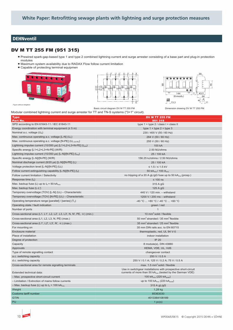
DEHNventil
DV M TT 255 (951 310)■ Prewired spark-gap-based type 1 and type 2 combined lightning current and surge arrester consisting of a base part and plug-in protection
modules■ Maximum system availability due to RADAX Flow follow current limitation■ Capable of protecting terminal equipment
Figure without obligation
Basic circuit diagram DV M TT 255 Dimension drawing DV M TT 255
Modular combined lightning current and surge arrester for TT and TN-S systems ("3+1" circuit).Type DV M TT 255 Part No. 951 310 SPD according to EN 61643-11 / IEC 61643-11 type 1 + type 2 / class I + class II Energy coordination with terminal equipment (≤ 5 m) type 1 + type 2 + type 3 Nominal a.c. voltage (UN) 230 / 400 V (50 / 60 Hz) Max. continuous operating a.c. voltage [L-N] (UC) 264 V (50 / 60 Hz) Max. continuous operating a.c. voltage [N-PE] (UC (N-PE)) 255 V (50 / 60 Hz) Lightning impulse current (10/350 µs) [L1+L2+L3+N-PE] (Itotal) 100 kA Specific energy [L1+L2+L3+N-PE] (W/R) 2.50 MJ/ohms Lightning impulse current (10/350 µs) [L-N]/[N-PE] (Iimp) 25 / 100 kA Specific energy [L-N]/[N-PE] (W/R) 156.25 kJ/ohms / 2.50 MJ/ohms Nominal discharge current (8/20 µs) [L-N]/[N-PE] (In) 25 / 100 kA Voltage protection level [L-N]/[N-PE] (UP) ≤ 1.5 / ≤ 1.5 kV Follow current extinguishing capability [L-N]/[N-PE] (Ifi) 50 kArms / 100 Arms Follow current limitation / Selectivity no tripping of a 20 A gL/gG fuse up to 50 kArms (prosp.) Response time (tA) ≤ 100 ns Max. backup fuse (L) up to IK = 50 kArms 315 A gG Max. backup fuse (L-L') 125 A gG Temporary overvoltage (TOV) [L-N] (UT) – Characteristic 440 V / 120 min. – withstand Temporary overvoltage (TOV) [N-PE] (UT) – Characteristic 1200 V / 200 ms – withstand Operating temperature range [parallel] / [series] (TU) -40 °C ... +80 °C / -40 °C ... +60 °C Operating state / fault indication green / red Number of ports 1 Cross-sectional area (L1, L1', L2, L2', L3, L3', N, N', PE, 9) (min.) 10 mm2 solid / flexible Cross-sectional area (L1, L2, L3, N, PE) (max.) 50 mm2 stranded / 35 mm2 flexible Cross-sectional area (L1', L2', L3', N', 9) (max.) 35 mm2 stranded / 25 mm2 flexible For mounting on 35 mm DIN rails acc. to EN 60715 Enclosure material thermoplastic, red, UL 94 V-0 Place of installation indoor installation Degree of protection IP 20 Capacity 8 module(s), DIN 43880 Approvals KEMA, VDE, UL, VdS
Extended technical data:Use in switchgear installations with prospective short-circuitcurrents of more than 50 kArms (tested by the German VDE)
– Max. prospective short-circuit current 100 kArms (220 kApeak) – Limitation / Extinction of mains follow currents up to 100 kArms (220 kApeak) – Max. backup fuse (L) up to IK = 100 kArms 315 A gL/gG Weight 1,27 kg Customs tariff number 85363030 GTIN 4013364108172 PU 1 pc(s)
10 WP004/E/0615 © Copyright 2015 DEHN + SÖHNE
White Paper: Retrofitting sewage plants with lightning and surge protection measures
DEHNventil
DV M TT 255 FM (951 315)■ Prewired spark-gap-based type 1 and type 2 combined lightning current and surge arrester consisting of a base part and plug-in protection
modules■ Maximum system availability due to RADAX Flow follow current limitation■ Capable of protecting terminal equipmen
Figure without obligation
Basic circuit diagram DV M TT 255 FM Dimension drawing DV M TT 255 FM
Modular combined lightning current and surge arrester for TT and TN-S systems ("3+1" circuit).Type DV M TT 255 FM Part No. 951 315 SPD according to EN 61643-11 / IEC 61643-11 type 1 + type 2 / class I + class II Energy coordination with terminal equipment (≤ 5 m) type 1 + type 2 + type 3 Nominal a.c. voltage (UN) 230 / 400 V (50 / 60 Hz) Max. continuous operating a.c. voltage [L-N] (UC) 264 V (50 / 60 Hz) Max. continuous operating a.c. voltage [N-PE] (UC (N-PE)) 255 V (50 / 60 Hz) Lightning impulse current (10/350 µs) [L1+L2+L3+N-PE] (Itotal) 100 kA Specific energy [L1+L2+L3+N-PE] (W/R) 2.50 MJ/ohms Lightning impulse current (10/350 µs) [L-N]/[N-PE] (Iimp) 25 / 100 kA Specific energy [L-N]/[N-PE] (W/R) 156.25 kJ/ohms / 2.50 MJ/ohms Nominal discharge current (8/20 µs) [L-N]/[N-PE] (In) 25 / 100 kA Voltage protection level [L-N]/[N-PE] (UP) ≤ 1.5 / ≤ 1.5 kV Follow current extinguishing capability [L-N]/[N-PE] (Ifi) 50 kArms / 100 Arms Follow current limitation / Selectivity no tripping of a 20 A gL/gG fuse up to 50 kArms (prosp.) Response time (tA) ≤ 100 ns Max. backup fuse (L) up to IK = 50 kArms 315 A gG Max. backup fuse (L-L') 125 A gG Temporary overvoltage (TOV) [L-N] (UT) – Characteristic 440 V / 120 min. – withstand Temporary overvoltage (TOV) [N-PE] (UT) – Characteristic 1200 V / 200 ms – withstand Operating temperature range [parallel] / [series] (TU) -40 °C ... +80 °C / -40 °C ... +60 °C Operating state / fault indication green / red Number of ports 1 Cross-sectional area (L1, L1', L2, L2', L3, L3', N, N', PE, 9) (min.) 10 mm2 solid / flexible Cross-sectional area (L1, L2, L3, N, PE) (max.) 50 mm2 stranded / 35 mm2 flexible Cross-sectional area (L1', L2', L3', N', 9) (max.) 35 mm2 stranded / 25 mm2 flexible For mounting on 35 mm DIN rails acc. to EN 60715 Enclosure material thermoplastic, red, UL 94 V-0 Place of installation indoor installation Degree of protection IP 20 Capacity 8 module(s), DIN 43880 Approvals KEMA, VDE, UL, VdS Type of remote signalling contact changeover contact a.c. switching capacity 250 V / 0.5 A d.c. switching capacity 250 V / 0.1 A; 125 V / 0.2 A; 75 V / 0.5 A Cross-sectional area for remote signalling terminals max. 1.5 mm2 solid / flexible
Extended technical data:Use in switchgear installations with prospective short-circuitcurrents of more than 50 kArms (tested by the German VDE)
– Max. prospective short-circuit current 100 kArms (220 kApeak) – Limitation / Extinction of mains follow currents up to 100 kArms (220 kApeak) – Max. backup fuse (L) up to IK = 100 kArms 315 A gL/gG Weight 1,28 kg Customs tariff number 85363030 GTIN 4013364108189 PU 1 pc(s)

11WP004/E/0615 © Copyright 2015 DEHN + SÖHNE
White Paper: Retrofitting sewage plants with lightning and surge protection measures
DEHNguard
DG M TT 2P 275 (952 110)■ Prewired complete unit consisting of a base part and plug-in protection modules■ High discharge capacity due to heavy-duty zinc oxide varistors / spark gaps■ High reliability due to "Thermo Dynamic Control" SPD monitoring device
Figure without obligation
Basic circuit diagram DG M TT 2P 275 Dimension drawing DG M TT 2P 275
Modular surge arrester for use in single-phase TT and TN systems ("1+1" circuit).Type DG M TT 2P 275 Part No. 952 110 SPD according to EN 61643-11 / IEC 61643-11 type 2 / class II Nominal a.c. voltage (UN) 230 V (50 / 60 Hz) Max. continuous operating a.c. voltage [L-N] (UC) 275 V (50 / 60 Hz) Max. continuous operating a.c. voltage [N-PE] (UC) 255 V (50 / 60 Hz) Nominal discharge current (8/20 µs) (In) 20 kA Max. discharge current (8/20 µs) (Imax) 40 kA Lightning impulse current (10/350 µs) [N-PE] (Iimp) 12 kA Voltage protection level [L-N] (UP) ≤ 1.5 kV Voltage protection level [L-N] at 5 kA (UP) ≤ 1 kV Voltage protection level [N-PE] (UP) ≤ 1.5 kV Follow current extinguishing capability [N-PE] (Ifi) 100 Arms Response time [L-N] (tA) ≤ 25 ns Response time [N-PE] (tA) ≤ 100 ns Max. mains-side overcurrent protection 125 A gG Short-circuit withstand capability for max. mains-side overcurrentprotection (ISCCR) 50 kArms Temporary overvoltage (TOV) [L-N] (UT) – Characteristic 335 V / 5 sec. – withstand Temporary overvoltage (TOV) [L-N] (UT) – Characteristic 440 V / 120 min. – safe failure Temporary overvoltage (TOV) [N-PE] (UT) – Characteristic 1200 V / 200 ms – withstand Operating temperature range (TU) -40 °C ... +80 °C Operating state / fault indication green / red Number of ports 1 Cross-sectional area (min.) 1.5 mm2 solid / flexible Cross-sectional area (max.) 35 mm2 stranded / 25 mm2 flexible For mounting on 35 mm DIN rails acc. to EN 60715 Enclosure material thermoplastic, red, UL 94 V-0 Place of installation indoor installation Degree of protection IP 20 Capacity 2 module(s), DIN 43880 Approvals KEMA, VDE, UL, VdS Weight 242 g Customs tariff number 85363030 GTIN 4013364108417 PU 1 pc(s)

12 WP004/E/0615 © Copyright 2015 DEHN + SÖHNE
White Paper: Retrofitting sewage plants with lightning and surge protection measures
DEHNguard
DG M TT 2P 275 FM (952 115)■ Prewired complete unit consisting of a base part and plug-in protection modules■ High discharge capacity due to heavy-duty zinc oxide varistors / spark gaps■ High reliability due to "Thermo Dynamic Control" SPD monitoring device
Figure without obligation
Basic circuit diagram DG M TT 2P 275 FM Dimension drawing DG M TT 2P 275 FM
Modular surge arrester for single-phase TT and TN systems ("1+1" circuit); with floating remote signalling contact.Type DG M TT 2P 275 FM Part No. 952 115 SPD according to EN 61643-11 / IEC 61643-11 type 2 / class II Nominal a.c. voltage (UN) 230 V (50 / 60 Hz) Max. continuous operating a.c. voltage [L-N] (UC) 275 V (50 / 60 Hz) Max. continuous operating a.c. voltage [N-PE] (UC) 255 V (50 / 60 Hz) Nominal discharge current (8/20 µs) (In) 20 kA Max. discharge current (8/20 µs) (Imax) 40 kA Lightning impulse current (10/350 µs) [N-PE] (Iimp) 12 kA Voltage protection level [L-N] (UP) ≤ 1.5 kV Voltage protection level [L-N] at 5 kA (UP) ≤ 1 kV Voltage protection level [N-PE] (UP) ≤ 1.5 kV Follow current extinguishing capability [N-PE] (Ifi) 100 Arms Response time [L-N] (tA) ≤ 25 ns Response time [N-PE] (tA) ≤ 100 ns Max. mains-side overcurrent protection 125 A gG Short-circuit withstand capability for max. mains-side overcurrentprotection (ISCCR) 50 kArms Temporary overvoltage (TOV) [L-N] (UT) – Characteristic 335 V / 5 sec. – withstand Temporary overvoltage (TOV) [L-N] (UT) – Characteristic 440 V / 120 min. – safe failure Temporary overvoltage (TOV) [N-PE] (UT) – Characteristic 1200 V / 200 ms – withstand Operating temperature range (TU) -40 °C ... +80 °C Operating state / fault indication green / red Number of ports 1 Cross-sectional area (min.) 1.5 mm2 solid / flexible Cross-sectional area (max.) 35 mm2 stranded / 25 mm2 flexible For mounting on 35 mm DIN rails acc. to EN 60715 Enclosure material thermoplastic, red, UL 94 V-0 Place of installation indoor installation Degree of protection IP 20 Capacity 2 module(s), DIN 43880 Approvals KEMA, VDE, UL, VdS Type of remote signalling contact changeover contact a.c. switching capacity 250 V / 0.5 A d.c. switching capacity 250 V / 0.1 A; 125 V / 0.2 A; 75 V / 0.5 A Cross-sectional area for remote signalling terminals max. 1.5 mm2 solid / flexible Weight 228 g Customs tariff number 85363030 GTIN 4013364108424 PU 1 pc(s)

13WP004/E/0615 © Copyright 2015 DEHN + SÖHNE
White Paper: Retrofitting sewage plants with lightning and surge protection measures
DEHNguard
DG M TN 275 (952 200)■ Prewired complete unit consisting of a base part and plug-in protection modules■ High discharge capacity due to heavy-duty zinc oxide varistors / spark gaps■ High reliability due to "Thermo Dynamic Control" SPD monitoring device
Figure without obligation
Basic circuit diagram DG M TN 275 Dimension drawing DG M TN 275
Modular surge arrester for use in single-phase TN systems.Type DG M TN 275Part No. 952 200SPD according to EN 61643-11 / IEC 61643-11 type 2 / class II Nominal a.c. voltage (UN) 230 V (50 / 60 Hz) Max. continuous operating a.c. voltage (UC) 275 V (50 / 60 Hz) Nominal discharge current (8/20 µs) (In) 20 kAMax. discharge current (8/20 µs) (Imax) 40 kAVoltage protection level (UP) ≤ 1.5 kVVoltage protection level at 5 kA (UP) ≤ 1 kVResponse time (tA) ≤ 25 nsMax. mains-side overcurrent protection 125 A gGShort-circuit withstand capability for max. mains-side overcurrentprotection (ISCCR) 50 kArms
Temporary overvoltage (TOV) (UT) – Characteristic 335 V / 5 sec. – withstand Temporary overvoltage (TOV) (UT) – Characteristic 440 V / 120 min. – safe failure Operating temperature range (TU) -40 °C ... +80 °C Operating state / fault indication green / red Number of ports 1
Cross-sectional area (min.) 1.5 mm2 solid / flexible
Cross-sectional area (max.) 35 mm2 stranded / 25 mm2 flexible For mounting on 35 mm DIN rails acc. to EN 60715 Enclosure material thermoplastic, red, UL 94 V-0 Place of installation indoor installation Degree of protection IP 20 Capacity 2 module(s), DIN 43880Approvals KEMA, VDE, UL, VdS Weight 229 gCustoms tariff number 85363030GTIN 4013364108394PU 1 pc(s)

14 WP004/E/0615 © Copyright 2015 DEHN + SÖHNE
White Paper: Retrofitting sewage plants with lightning and surge protection measures
DEHNguard
DG M TN 275 FM (952 205)■ Prewired complete unit consisting of a base part and plug-in protection modules■ High discharge capacity due to heavy-duty zinc oxide varistors / spark gaps■ High reliability due to "Thermo Dynamic Control" SPD monitoring device
Figure without obligation
Basic circuit diagram DG M TN 275 FM Dimension drawing DG M TN 275 FM
Modular surge arrester for use in single-phase TN systems; with floating remote signalling contact.Type DG M TN 275 FM Part No. 952 205 SPD according to EN 61643-11 / IEC 61643-11 type 2 / class II Nominal a.c. voltage (UN) 230 V (50 / 60 Hz) Max. continuous operating a.c. voltage (UC) 275 V (50 / 60 Hz) Nominal discharge current (8/20 µs) (In) 20 kA Max. discharge current (8/20 µs) (Imax) 40 kA Voltage protection level (UP) ≤ 1.5 kV Voltage protection level at 5 kA (UP) ≤ 1 kV Response time (tA) ≤ 25 ns Max. mains-side overcurrent protection 125 A gG Short-circuit withstand capability for max. mains-side overcurrentprotection (ISCCR) 50 kArms Temporary overvoltage (TOV) (UT) – Characteristic 335 V / 5 sec. – withstand Temporary overvoltage (TOV) (UT) – Characteristic 440 V / 120 min. – safe failure Operating temperature range (TU) -40 °C ... +80 °C Operating state / fault indication green / red Number of ports 1 Cross-sectional area (min.) 1.5 mm2 solid / flexible Cross-sectional area (max.) 35 mm2 stranded / 25 mm2 flexible For mounting on 35 mm DIN rails acc. to EN 60715 Enclosure material thermoplastic, red, UL 94 V-0 Place of installation indoor installation Degree of protection IP 20 Capacity 2 module(s), DIN 43880 Approvals KEMA, VDE, UL, VdS Type of remote signalling contact changeover contact a.c. switching capacity 250 V / 0.5 A d.c. switching capacity 250 V / 0.1 A; 125 V / 0.2 A; 75 V / 0.5 A Cross-sectional area for remote signalling terminals max. 1.5 mm2 solid / flexible Weight 232 g Customs tariff number 85363030 GTIN 4013364108400 PU 1 pc(s)

15WP004/E/0615 © Copyright 2015 DEHN + SÖHNE
White Paper: Retrofitting sewage plants with lightning and surge protection measures
BLITZDUCTOR XT
BXT ML2 BE S 24 (920 224)■ LifeCheck SPD monitoring function■ Optimal protection of two single lines and the cable shield■ For use in conformity with the lightning protection zone concept at the boundaries from 0A –2 and higher
Figure without obligation
Basic circuit diagram BXT ML2 BE S 24 Dimension drawing BXT ML2 BE S 24
Space-saving combined lightning current and surge arrester module with LifeCheck feature for protecting two single lines sharing a common referencepotential as well as unbalanced interfaces, with direct or indirect shield earthing. If LifeCheck detects thermal or electrical overload, the arrester has tobe replaced. This status is indicated contactlessly by the DEHNrecord LC / SCM / MCM reader.Type BXT ML2 BE S 24 Part No. 920 224 SPD monitoring system LifeCheck SPD class M Nominal voltage (UN) 24 V Max. continuous operating d.c. voltage (UC) 33 V Max. continuous operating a.c. voltage (UC) 23.3 V Nominal current at 45 °C (IL) 0.75 A D1 Total lightning impulse current (10/350 µs) (Iimp) 9 kA D1 Lightning impulse current (10/350 µs) per line (Iimp) 2.5 kA C2 Total nominal discharge current (8/20 µs) (In) 20 kA C2 Nominal discharge current (8/20 µs) per line (In) 10 kA Voltage protection level line-line for Iimp D1 (Up) ≤ 102 V Voltage protection level line-PG for Iimp D1 (Up) ≤ 66 V Voltage protection level line-line at 1 kV/µs C3 (Up) ≤ 90 V Voltage protection level line-PG at 1 kV/µs C3 (Up) ≤ 45 V Series resistance per line 1.8 ohm(s) Cut-off frequency line-PG (fG) 6.8 MHz Capacitance line-line (C) ≤ 0.5 nF Capacitance line-PG (C) ≤ 1.0 nF Operating temperature range (TU) -40 °C ... +80 °C Degree of protection (plugged-in) IP 20 Pluggable into BXT BAS / BSP BAS 4 base part Earthing via BXT BAS / BSP BAS 4 base part Enclosure material polyamide PA 6.6 Colour yellow Test standards IEC 61643-21 / EN 61643-21, UL 497B SIL classification up to SIL3 *) ATEX approvals DEKRA 11ATEX0089 X: II 3 G Ex nA IIC T4 Gc IECEx approvals DEK 11.0032X: Ex nA IIC T4 Gc CSA & USA Hazloc approvals (1) 2516389: Class I Div. 2 GP A, B, C, D T4 CSA & USA Hazloc approvals (2) 2516389: Class I Zone 2, AEx nA IIC T4 Approvals CSA, GOST, VdS Weight 37 g Customs tariff number 85363010 GTIN 4013364117785 PU 1 pc(s)
*)For more detailed information, please visit www.dehn-international.com.

16 WP004/E/0615 © Copyright 2015 DEHN + SÖHNE
White Paper: Retrofitting sewage plants with lightning and surge protection measures
BLITZDUCTOR XT
BXT ML2 BD 180 (920 247)■ LifeCheck SPD monitoring function■ Optimal protection of one pair■ For installation in conformity with the lightning protection zone concept at the boundaries from 0A –2 and higher
Figure without obligation
Basic circuit diagram BXT ML2 BD 180 Dimension drawing BXT ML2 BD 180
Space-saving combined lightning current and surge arrester module with LifeCheck feature for protecting one pair of unearthed balanced interfaces. IfLifeCheck detects thermal or electrical overload, the arrester has to be replaced. This status is indicated contactlessly by the DEHNrecord LC / SCM /MCM reader.Type BXT ML2 BD 180 Part No. 920 247 SPD monitoring system LifeCheck SPD class L Nominal voltage (UN) 180 V Max. continuous operating d.c. voltage (UC) 180 V Max. continuous operating a.c. voltage (UC) 127 V Nominal current at 45 °C (IL) 0.75 A D1 Total lightning impulse current (10/350 µs) (Iimp) 5 kA D1 Lightning impulse current (10/350 µs) per line (Iimp) 2.5 kA C2 Total nominal discharge current (8/20 µs) (In) 20 kA C2 Nominal discharge current (8/20 µs) per line (In) 10 kA Voltage protection level line-line for Iimp D1 (Up) ≤ 270 V Voltage protection level line-PG for Iimp D1 (Up) ≤ 550 V Voltage protection level line-line at 1 kV/µs C3 (Up) ≤ 250 V Voltage protection level line-PG at 1 kV/µs C3 (Up) ≤ 550 V Series resistance per line 1.8 ohm(s) Cut-off frequency line-line (fG) 25.0 MHz Capacitance line-line (C) ≤ 240 pF Capacitance line-PG (C) ≤ 16 pF Operating temperature range (TU) -40 °C ... +80 °C Degree of protection (plugged-in) IP 20 Pluggable into BXT BAS / BSP BAS 4 base part Earthing via BXT BAS / BSP BAS 4 base part Enclosure material polyamide PA 6.6 Colour yellow Test standards IEC 61643-21 / EN 61643-21, UL 497B SIL classification up to SIL3 *) ATEX approvals DEKRA 11ATEX0089 X: II 3 G Ex nA IIC T4 Gc IECEx approvals DEK 11.0032X: Ex nA IIC T4 Gc CSA & USA Hazloc approvals (1) 2516389: Class I Div. 2 GP A, B, C, D T4 CSA & USA Hazloc approvals (2) 2516389: Class I Zone 2, AEx nA IIC T4 Approvals CSA, GOST, VdS Weight 43 g Customs tariff number 85363010 GTIN 4013364116078 PU 1 pc(s)
*) For more detailed information, please visit www.dehn-international.com.

17WP004/E/0615 © Copyright 2015 DEHN + SÖHNE
White Paper: Retrofitting sewage plants with lightning and surge protection measures
BLITZDUCTOR XT
BXT ML2 BD HFS 5 (920 271)■ LifeCheck SPD monitoring function■ Minimal signal interference■ For installation in conformity with the lightning protection zone concept at the boundaries from 0A –2 and higher
Figure without obligation
Basic circuit diagram BXT ML2 BD HFS Dimension drawing BXT ML2 BD HFS
Space-saving combined lightning current and surge arrester module with LifeCheck feature for protecting one pair of unearthed high-frequency bussystems or video transmission systems, with direct or indirect shield earthing. If LifeCheck detects thermal or electrical overload, the arrester has to bereplaced. This status is indicated contactlessly by the DEHNrecord LC / SCM / MCM reader.Type BXT ML2 BD HFS 5 Part No. 920 271 SPD monitoring system LifeCheck SPD class M Nominal voltage (UN) 5 V Max. continuous operating d.c. voltage (UC) 6.0 V Max. continuous operating a.c. voltage (UC) 4.2 V Nominal current at 45 °C (IL) 1.0 A D1 Total lightning impulse current (10/350 µs) (Iimp) 9 kA D1 Lightning impulse current (10/350 µs) per line (Iimp) 2.5 kA C2 Total nominal discharge current (8/20 µs) (In) 20 kA C2 Nominal discharge current (8/20 µs) per line (In) 10 kA Voltage protection level line-line for Iimp D1 (Up) ≤ 25 V Voltage protection level line-PG for Iimp D1 (Up) ≤ 550 V Voltage protection level line-line at 1 kV/µs C3 (Up) ≤ 11 V Voltage protection level line-PG at 1 kV/µs C3 (Up) ≤ 550 V Series resistance per line 1.0 ohm(s) Cut-off frequency line-line (fG) 100.0 MHz Capacitance line-line (C) ≤ 25 pF Capacitance line-PG (C) ≤ 25 pF Operating temperature range (TU) -40 °C ... +80 °C Degree of protection (plugged-in) IP 20 Pluggable into BXT BAS / BSP BAS 4 base part Earthing via BXT BAS / BSP BAS 4 base part Enclosure material polyamide PA 6.6 Colour yellow Test standards IEC 61643-21 / EN 61643-21, UL 497B SIL classification up to SIL3 *) ATEX approvals DEKRA 11ATEX0089 X: II 3 G Ex nA IIC T4 Gc IECEx approvals DEK 11.0032X: Ex nA IIC T4 Gc CSA & USA Hazloc approvals (1) 2516389: Class I Div. 2 GP A, B, C, D T4 CSA & USA Hazloc approvals (2) 2516389: Class I Zone 2, AEx nA IIC T4 Approvals CSA, UL, GOST, VdS Weight 22 g Customs tariff number 85363010 GTIN 4013364117556 PU 1 pc(s)
*) For more detailed information, please visit www.dehn-international.com.

18 WP004/E/0615 © Copyright 2015 DEHN + SÖHNE
White Paper: Retrofitting sewage plants with lightning and surge protection measures
BLITZDUCTOR XT
BXT ML4 BE 24 (920 324)■ LifeCheck SPD monitoring function■ Optimal protection of four single lines■ For installation in conformity with the lightning protection zone concept at the boundaries from 0A – 2 and higher
Figure without obligation
Basic circuit diagram BXT ML4 BE 24 Dimension drawing BXT ML4 BE 24
Space-saving combined lightning current and surge arrester module with LifeCheck feature for protecting four single lines sharing a commonreference potential as well as unbalanced interfaces. If LifeCheck detects thermal or electrical overload, the arrester has to be replaced. This status isindicated contactlessly by the DEHNrecord LC / SCM / MCM reader.Type BXT ML4 BE 24 Part No. 920 324 SPD monitoring system LifeCheck SPD class M Nominal voltage (UN) 24 V Max. continuous operating d.c. voltage (UC) 33 V Max. continuous operating a.c. voltage (UC) 23.3 V Nominal current at 45 °C (IL) 0.75 A D1 Total lightning impulse current (10/350 µs) (Iimp) 10 kA D1 Lightning impulse current (10/350 µs) per line (Iimp) 2.5 kA C2 Total nominal discharge current (8/20 µs) (In) 20 kA C2 Nominal discharge current (8/20 µs) per line (In) 10 kA Voltage protection level line-line for Iimp D1 (Up) ≤ 102 V Voltage protection level line-PG for Iimp D1 (Up) ≤ 66 V Voltage protection level line-line at 1 kV/µs C3 (Up) ≤ 90 V Voltage protection level line-PG at 1 kV/µs C3 (Up) ≤ 45 V Series resistance per line 1.8 ohm(s) Cut-off frequency line-PG (fG) 6.8 MHz Capacitance line-line (C) ≤ 0.5 nF Capacitance line-PG (C) ≤ 1.0 nF Operating temperature range (TU) -40 °C ... +80 °C Degree of protection (plugged-in) IP 20 Pluggable into BXT BAS / BSP BAS 4 base part Earthing via BXT BAS / BSP BAS 4 base part Enclosure material polyamide PA 6.6 Colour yellow Test standards IEC 61643-21 / EN 61643-21, UL 497B SIL classification up to SIL3 *) ATEX approvals DEKRA 11ATEX0089 X: II 3 G Ex nA IIC T4 Gc IECEx approvals DEK 11.0032X: Ex nA IIC T4 Gc CSA & USA Hazloc approvals (1) 2516389: Class I Div. 2 GP A, B, C, D T4 CSA & USA Hazloc approvals (2) 2516389: Class I Zone 2, AEx nA IIC T4 Approvals CSA, VdS, UL, GOST Weight 38 g Customs tariff number 85363010 GTIN 4013364109056 PU 1 pc(s)
*) For more detailed information, please visit www.dehn-international.com.

19WP004/E/0615 © Copyright 2015 DEHN + SÖHNE
White Paper: Retrofitting sewage plants with lightning and surge protection measures
BLITZDUCTOR XT
BXT ML4 BD 180 (920 347)■ LifeCheck SPD monitoring function■ Optimal protection of two pairs■ For installation in conformity with the lightning protection zone concept at the boundaries from 0A –2 and higher
Figure without obligation
Basic circuit diagram BXT ML4 BD 180 Dimension drawing BXT ML4 BD 180
Space-saving combined lightning current and surge arrester module with LifeCheck feature for protecting two pairs of unearthed balanced interfaces.If LifeCheck detects thermal or electrical overload, the arrester has to be replaced. This status is indicated contactlessly by the DEHNrecord LC /SCM / MCM reader.Type BXT ML4 BD 180 Part No. 920 347 SPD monitoring system LifeCheck SPD class L Nominal voltage (UN) 180 V Max. continuous operating d.c. voltage (UC) 180 V Max. continuous operating a.c. voltage (UC) 127 V Nominal current at 45 °C (IL) 0.75 A D1 Total lightning impulse current (10/350 µs) (Iimp) 10 kA D1 Lightning impulse current (10/350 µs) per line (Iimp) 2.5 kA C2 Total nominal discharge current (8/20 µs) (In) 20 kA C2 Nominal discharge current (8/20 µs) per line (In) 10 kA Voltage protection level line-line for Iimp D1 (Up) ≤ 270 V Voltage protection level line-PG for Iimp D1 (Up) ≤ 550 V Voltage protection level line-line at 1 kV/µs C3 (Up) ≤ 250 V Voltage protection level line-PG at 1 kV/µs C3 (Up) ≤ 550 V Series resistance per line 1.8 ohm(s) Cut-off frequency line-line (fG) 25.0 MHz Capacitance line-line (C) ≤ 240 pF Capacitance line-PG (C) ≤ 16 pF Operating temperature range (TU) -40 °C ... +80 °C Degree of protection (plugged-in) IP 20 Pluggable into BXT BAS / BSP BAS 4 base part Earthing via BXT BAS / BSP BAS 4 base part Enclosure material polyamide PA 6.6 Colour yellow Test standards IEC 61643-21 / EN 61643-21, UL 497B SIL classification up to SIL3 *) ATEX approvals DEKRA 11ATEX0089 X: II 3 G Ex nA IIC T4 Gc IECEx approvals DEK 11.0032X: Ex nA IIC T4 Gc CSA & USA Hazloc approvals (1) 2516389: Class I Div. 2 GP A, B, C, D T4 CSA & USA Hazloc approvals (2) 2516389: Class I Zone 2, AEx nA IIC T4 Approvals CSA, VdS, UL, GOST Weight 24 g Customs tariff number 85363010 GTIN 4013364109018 PU 1 pc(s)
*)For more detailed information, please visit www.dehn-international.com.

20 WP004/E/0615 © Copyright 2015 DEHN + SÖHNE
White Paper: Retrofitting sewage plants with lightning and surge protection measures
BLITZDUCTOR XT
BXT ML2 BD S EX 24 (920 280)■ For universal use, with LifeCheck monitoring function■ Self-capacitance and self-inductance negligibly small■ For installation in conformity with the lightning protection zone concept at the boundaries from 0B –2 and higher
Figure without obligation
Basic circuit diagram BXT ML2 BD S EX 24 Dimension drawing BXT ML2 BD S EX 24
Space-saving surge arrester module with LifeCheck feature for protecting one pair of intrinsically safe measuring circuits and bus systems, direct orindirect shield earthing. Insulation strength > 500 V line-earth.If LifeCheck detects thermal or electrical overload, the arrester has to be replaced. This status is indicated contactlessly by DEHNrecord LC / SCM /MCM.Type BXT ML2 BD S EX 24 Part No. 920 280 SPD class T SPD monitoring LifeCheck Nominal voltage (UN) 24 V Max. continuous operating d.c. voltage (Uc) 33 V Max. continuous operating a.c. voltage (Uc) 23.3 V Max. input voltage acc. to EN 60079-11 (Ui) 30 V Max. input current acc. to EN 60079-11 (Ii) 0.5 A D1 Total lightning impulse current (10/350 µs) (Iimp) 4 kA D1 Lightning impulse current (10/350 µs) per line (Iimp) 1 kA C2 Total nominal discharge current (8/20 µs) (In) 10 kA C2 Nominal discharge current (8/20 µs) per line (In) 5 kA Voltage protection level line-line for Iimp D1 (Up) ≤ 50 V Voltage protection level line-PG for Iimp D1 (Up) ≤ 1300 V Voltage protection level line-line for In C2 (Up) ≤ 52 V Voltage protection level line-PG for In C2 (Up) ≤ 1400 V Voltage protection level line-line at 1 kV/µs C3 (Up) ≤ 45 V Voltage protection level line-PG at 1 kV/µs C3 (Up) ≤ 1100 V Series resistance per line 1.0 ohm Cut-off frequency line-line (fG) 6 MHz Capacitance line-line (C) ≤ 1.0 nF Capacitance line-PG (C) ≤ 16 pF Operating temperature range (TU) -40 °C ... +80 °C Degree of protection (plugged-in) IP 20 Plugs into base part Earthing via base part Enclosure material polyamide PA 6.6 Colour blue Test standards IEC 61643-21 / EN 61643-21 ATEX approvals (1) KEMA 06ATEX0274 X: II 2 (1) G Ex ia [ia Ga] IIC T4 ... T6 Gb ATEX approvals (2) KEMA 06ATEX0274 X: II 2 G Ex ib IIC T4 ... T6 Gb IECEx approvals (1) DEK 11.0078X: Ex ia [ia Ga] IIC T4 ... T6 Gb IECEx approvals (2) DEK 11.0078X: Ex ib IIC T4 ... T6 Gb CSA & USA Hazloc approvals (1) 70000011: Class I Div. 1; Class I Zone 1 CSA & USA Hazloc approvals (2) 70000011: Ex ia [ia] IIC T4 ... T6 Approvals GOST Weight 22 g Customs tariff number 85363010 GTIN 4013364142138 PU 1 pc(s)

21WP004/E/0615 © Copyright 2015 DEHN + SÖHNE
White Paper: Retrofitting sewage plants with lightning and surge protection measures
BLITZDUCTOR XT
BXT ML4 BD EX 24 (920 381)■ For universal use, with LifeCheck monitoring function■ Self-capacitance and self-inductance negligibly small■ For installation in conformity with the lightning protection zone concept at the boundaries from 0B –2 and higher
Figure without obligation
Basic circuit diagram BXT ML4 BD EX 24 Dimension drawing BXT ML4 BD EX 24
Space-saving surge arrester module with LifeCheck feature for protecting two pairs of intrinsically safe measuring circuits and bus systems, meetsFISCO requirements. ATEX. Insulation strength > 500 V line-earth.If LifeCheck detects thermal or electrical overload, the arrester has to be replaced. This status is indicated contactlessly by DEHNrecord LC / SCM /MCM.Type BXT ML4 BD EX 24 Part No. 920 381 SPD class T SPD monitoring LifeCheck Nominal voltage (UN) 24 V Max. continuous operating d.c. voltage (Uc) 33 V Max. continuous operating a.c. voltage (Uc) 23 V Max. input voltage acc. to EN 60079-11 (Ui) 30 V Max. input current acc. to EN 60079-11 (Ii) 0.5 A D1 Total lightning impulse current (10/350 µs) (Iimp) 4 kA D1 Lightning impulse current (10/350 µs) per line (Iimp) 1 kA C2 Total nominal discharge current (8/20 µs) (In) 20 kA C2 Nominal discharge current (8/20 µs) per line (In) 5 kA Voltage protection level line-line for Iimp D1 (Up) ≤ 50 V Voltage protection level line-PG for Iimp D1 (Up) ≤ 1300 V Voltage protection level line-line for In C2 (Up) ≤ 52 V Voltage protection level line-PG for In C2 (Up) ≤ 1400 V Voltage protection level line-line at 1 kV/µs C3 (Up) ≤ 45 V Voltage protection level line-PG at 1 kV/µs C3 (Up) ≤ 1100 V Series resistance per line 1.0 ohm Cut-off frequency line-line (fG) 7.7 MHz Capacitance line-line (C) ≤ 0.8 nF Capacitance line-PG (C) ≤ 16 pF Operating temperature range (TU) -40 °C ... +80 °C Degree of protection (plugged-in) IP 20 Plugs into base part Earthing via base part Enclosure material polyamide PA 6.6 Colour blue Test standards IEC 61643-21 / EN 61643-21, UL 497B SIL classification up to SIL3 *) ATEX approvals (1) KEMA 06ATEX0274 X: II 2 (1) G Ex ia [ia Ga] IIC T4 ... T6 Gb ATEX approvals (2) KEMA 06ATEX0274 X: II 2 G Ex ib IIC T4 ... T6 Gb IECEx approvals (1) DEK 11.0078X: Ex ia [ia Ga] IIC T4 ... T6 Gb IECEx approvals (2) DEK 11.0078X: Ex ib IIC T4 ... T6 Gb CSA & USA Hazloc approvals (1) 70000011: Class I Div. 1; Class I Zone 1 CSA & USA Hazloc approvals (2) 70000011: Ex ia [ia] IIC T4 ... T6 Approvals CSA, GOST Weight 23 g Customs tariff number 85363010 GTIN 4013364109025 PU 1 pc(s)
*) For more detailed information, please visit www.dehn-international.com.

22 WP004/E/0615 © Copyright 2015 DEHN + SÖHNE
White Paper: Retrofitting sewage plants with lightning and surge protection measures
BLITZDUCTOR XT
BXT BAS (920 300)■ Four-pole version for universal use with all types of BSP and BXT / BXTU protection modules■ No signal interruption if the protection module is removed■ Universal design without protection elements
Figure without obligation
Basic circuit diagram with and without plugged-in module Dimension drawing BXT BAS
The BLITZDUCTOR XT base part is a very space-saving and universal four-pole feed-through terminal for the insertion of a protection module withoutsignal interruption if the protection module is removed. The snap-in mechanism at the supporting foot of the base part allows the protection moduleto be safely earthed via the DIN rail. Since no components of the protective circuit are situated in the base part, only the protection modules must bemaintained.Type BXT BAS Part No. 920 300 Operating temperature range (TU) -40 °C ... +80 °C Degree of protection IP 20 For mounting on 35 mm DIN rails acc. to EN 60715 Connection (input / output) screw / screw Signal disconnection no Cross-sectional area, solid 0.08-4 mm2 Cross-sectional area, flexible 0.08-2.5 mm2 Tightening torque (terminals) 0.4 Nm Earthing via 35 mm DIN rails acc. to EN 60715 Enclosure material polyamide PA 6.6 Colour yellow ATEX approvals DEKRA 11ATEX0089 X: II 3 G Ex nA IIC T4 Gc *) IECEx approvals DEK 11.0032X: Ex nA IIC T4 Gc *) Approvals CSA, VdS, UL, GOST Weight 34 g Customs tariff number 85369010 GTIN 4013364109179 PU 1 pc(s)
*) only in connection with an approved protection module

23WP004/E/0615 © Copyright 2015 DEHN + SÖHNE
White Paper: Retrofitting sewage plants with lightning and surge protection measures
BLITZDUCTOR XT
BXT BAS EX (920 301)■ Four-pole and universal base part for all types of intrinsically safe protection modules■ No signal interruption if the protection module is removed■ Universal design without protection elements
Figure without obligation
Basic circuit diagram with and without module Dimension drawing BXT BAS EX
BLITZDUCTOR XT base part for use as an extremely space-saving and universal four-pole feed-through terminal for intrinsically safe circuits for theinsertion of the protection module, no signal disconnection if the protection module is removed. The snap-in mechanism at the supporting foot of thebase part allows the device to be safely earthed via the DIN rail. Since no components of the protective circuit are situated in the base part, only theprotection modules must be maintained.Type BXT BAS EX Part No. 920 301 Operating temperature range -40 °C ... +80 °C Degree of protection IP 20 For mounting on 35 mm DINs rails acc. to EN 60715 Connection (input / output) screw / screw Cross-sectional area, solid 0.08-4 mm2 Cross-sectional area, flexible 0.08-2.5 mm2 Tightening torque (terminals) 0.4 Nm Earthing via 35 mm DIN rails acc. to EN 60715 Enclosure material polyamide PA 6.6 Colour blue ATEX approvals (1) KEMA 06ATEX0274 X: II 2 (1) G Ex ia [ia Ga] IIC T4 ... T6 Gb *) ATEX approvals (2) KEMA 06ATEX0274 X: II 2 G Ex ib IIC T4 ... T6, Gb *) IECEx approvals (1) DEK 11.0078X: Ex ia [ia Ga] IIC T4 ... T6 Gb *) IECEx approvals (2) DEK 11.0078X: Ex ib IIC T4 ... T6 Gb *) CSA & USA Hazloc approvals (1) 70000011: Class I Div. 1; Class I Zone 1 CSA & USA Hazloc approvals (2) 70000011: Ex ia [ia] IIC T4 ... T6 Approvals UL, CSA, GOST Weight 53 g Customs tariff number 85369010 GTIN 4013364109186 PU 1 pc(s)
*) only in connection with an approved protection module

WP004/E/0615 © Copyright 2015 DEHN + SÖHNE
Type designations of products mentioned in the white paper being at the same time registered trademarks are not especially marked. So if there is no marking of ™ or ® this does not mean that the type designation is a free trade name. Neither it can be seen whether patents or utility models and other intellectual and industrial property rights are available. We reserve the right to introduce changes in performance, configuration and technology, dimensions, weights and materials in the course of technical progress. The figures are shown without obligation. Misprints, errors and modifications excepted. Reproduction in any form whatsoever is forbidden without our authorisation.
actiVsense, BLITZDUCTOR, BLITZPLANER, DEHN, DEHN Logo, DEHN schützt, DEHNbloc, DEHNfix, DEHNgrip, DEHNguard, DEHNport, DEHNQUICK, DEHNrapid, DEHNshield, DEHNsnap, DEHNventil, HVI, LifeCheck, Red/Line are protected by German Trade Mark, by Community Trade Mark (EU) and/or in other countries.
Surge Protection DEHN + SÖHNE Hans-Dehn-Str. 1 Tel. +49 9181 906-0Lightning Protection GmbH + Co.KG. Postfach 1640 Fax +49 9181 906-1100Safety Equipment 92306 Neumarkt [email protected] protects. Germany www.dehn-international.com
www.dehn-international.com/partners
www.dehn-international.com/partners