
WP uWave Rev 9 - bridgewave.com · Ericsson President and CEO Hans Vestberg estimated that by 2020...
11
WHITE PAPER Page 1 of 11 FlexPort ® µWave A Better Approach to High-Capacity Microwave Backhaul
Transcript of WP uWave Rev 9 - bridgewave.com · Ericsson President and CEO Hans Vestberg estimated that by 2020...

WHITE PAPER
Page 1 of 11
FlexPort® µWave A Better Approach to High-Capacity
Microwave Backhaul
WHITE PAPER
Page 2 of 11
The explosive need for capacity
The need for backhaul capacity in mobile networks is exploding. The increasing presence of smart phones and the expectation of users
that these phones provide the same experience as a desktop computer is the major driving force behind the proliferation of mobile data
traffic. These devices are performing more and more functions and have features that require huge amounts of bandwidth. December
2009 marks the first time that data traffic exceeded voice generated calls. In a keynote speech at the Monaco Media Forum 2010,
Ericsson President and CEO Hans Vestberg estimated that by 2020 there will be 50 billion connected devices! According to the Cisco
Visual Networking Index Global Mobile Data Forecast, 2009-2014, by 2014 mobile traffic will have increased 39 times over 2009 levels
while almost 66% of the mobile traffic will be video.
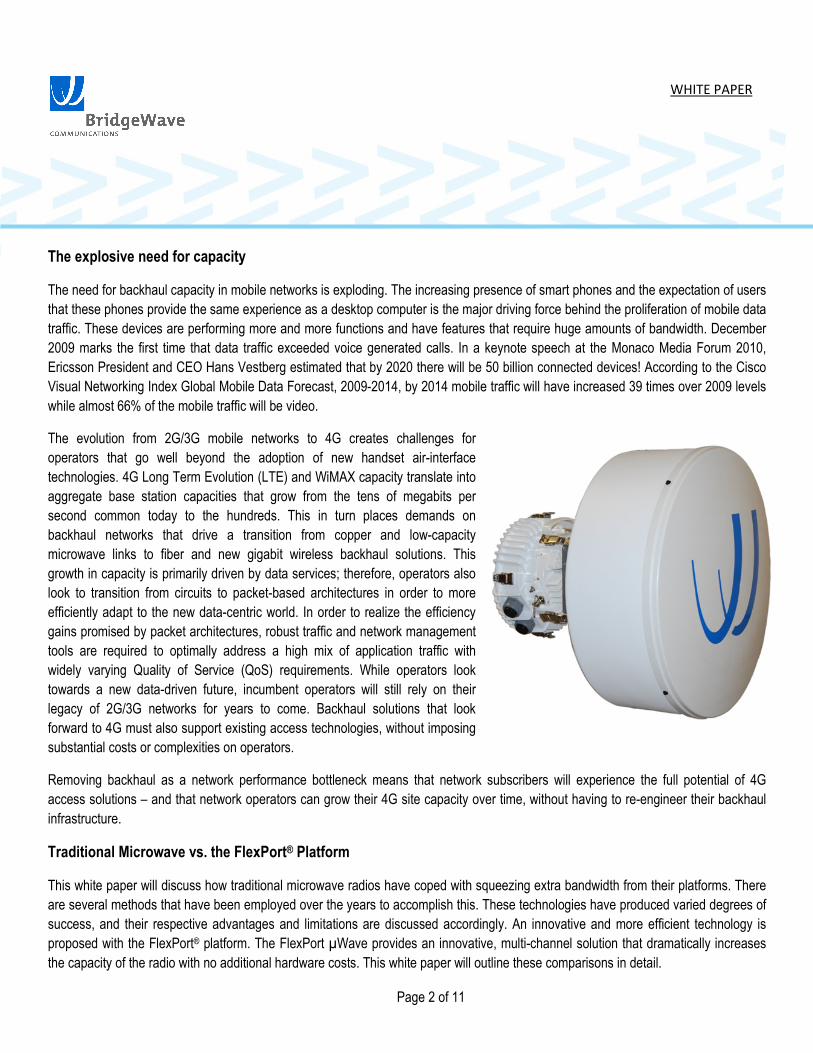
The evolution from 2G/3G mobile networks to 4G creates challenges for
operators that go well beyond the adoption of new handset air-interface
technologies. 4G Long Term Evolution (LTE) and WiMAX capacity translate into
aggregate base station capacities that grow from the tens of megabits per
second common today to the hundreds. This in turn places demands on
backhaul networks that drive a transition from copper and low-capacity
microwave links to fiber and new gigabit wireless backhaul solutions. This
growth in capacity is primarily driven by data services; therefore, operators also
look to transition from circuits to packet-based architectures in order to more
efficiently adapt to the new data-centric world. In order to realize the efficiency
gains promised by packet architectures, robust traffic and network management
tools are required to optimally address a high mix of application traffic with
widely varying Quality of Service (QoS) requirements. While operators look
towards a new data-driven future, incumbent operators will still rely on their
legacy of 2G/3G networks for years to come. Backhaul solutions that look
forward to 4G must also support existing access technologies, without imposing
substantial costs or complexities on operators.
Removing backhaul as a network performance bottleneck means that network subscribers will experience the full potential of 4G
access solutions – and that network operators can grow their 4G site capacity over time, without having to re-engineer their backhaul
infrastructure.
Traditional Microwave vs. the FlexPort® Platform
This white paper will discuss how traditional microwave radios have coped with squeezing extra bandwidth from their platforms. There
are several methods that have been employed over the years to accomplish this. These technologies have produced varied degrees of
success, and their respective advantages and limitations are discussed accordingly. An innovative and more efficient technology is
proposed with the FlexPort® platform. The FlexPort µWave provides an innovative, multi-channel solution that dramatically increases
the capacity of the radio with no additional hardware costs. This white paper will outline these comparisons in detail.
WHITE PAPER
Page 3 of 11
Traditional methods of squeezing more capacity out of a microwave link
Typical microwave radio solutions in the 6 to 38 GHz range are limited to capacities of around 350 Mbps per RF channel, due to narrow
spectrum allocations, the use of high order modulation, and narrow channel bandwidth limits. The only way to reach gigabit capacities
using these links is to multiply the number of radio transceivers and in turn increase the hardware costs of the link.
These traditional methods of providing “gigabit” speeds by utilizing microwave frequency solutions are inefficient in their
implementation, yield less than true gigabit throughput, and yield higher CAPEX costs for the user. Radio systems that are designed to
start off at initial capacities of 10 ~ 50 Mbps data rates and have the capability of expanding to 350 Mbps via a software upgrade are
simply not designed for high capacity full-rate gigabit transport. As such, to achieve higher capacities, manufacturers must cope with
taking these lower capacity solutions and doubling the hardware and/or adding intricate interference cancellation (XPIC) or
compression technologies to achieve near gigabit speeds.
Split-Mount Architecture
Split-mount architecture is among the most popular microwave designs worldwide. This type of architecture involves the use of indoor
and outdoor hardware typically called Indoor Units (IDU) and Outdoor Units (ODU) and an interconnecting coaxial cable (IFL). This
design has several advantages of flexibility and convenience in allowing the operator to easily access a variety of TDM and IP
connections from inside the building or equipment cabinet.
The evolution of split mount design saw the IDU morph from a full rack space unit capable of generating a single data transmission to
multiple plug-in cards supporting multiple carriers emanating from the same box. However, the limitation has always been in the
outdoor component of the radio and multiple outdoor units are needed to support the multiple carriers from the IDU to achieve near
gigabit speeds. The initial costs of a 350 Mbps circuit are relatively low, which allows the operator to start off his or her back-haul link
with a low CAPEX; however, the subsequent costs to upgrade the link to a “gigabit” speed scales linearly. This translates into doubling
hardware costs to achieve less than true GigE speed.
WHITE PAPER
Page 4 of 11
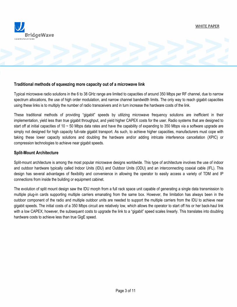
Typical Split-Mount Microwave Configuration
While split-mount architecture remains a popular design, it is not optimal for full-rate gigabit transport. The disadvantages of split-mount
architecture for gigabit speeds are the added cost of an additional IDU and the expensive rack space needed to house it, as well as the
added installation time. Certain microwave solutions allow the user to have the ability to insert a plug-in module into an IDU chassis
while other solutions require a second IDU to be installed in the rack in order to add a second 350 Mbps data link. In either of these
cases a second IFL cable must be pulled to the ODU, adding additional labor costs to increase capacity over the link.
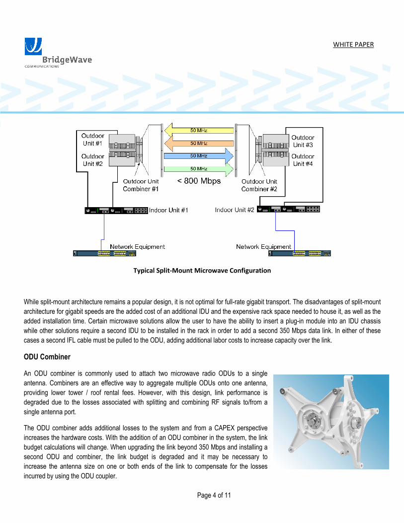
ODU Combiner
An ODU combiner is commonly used to attach two microwave radio ODUs to a single
antenna. Combiners are an effective way to aggregate multiple ODUs onto one antenna,
providing lower tower / roof rental fees. However, with this design, link performance is
degraded due to the losses associated with splitting and combining RF signals to/from a
single antenna port.
The ODU combiner adds additional losses to the system and from a CAPEX perspective
increases the hardware costs. With the addition of an ODU combiner in the system, the link
budget calculations will change. When upgrading the link beyond 350 Mbps and installing a
second ODU and combiner, the link budget is degraded and it may be necessary to
increase the antenna size on one or both ends of the link to compensate for the losses
incurred by using the ODU coupler.

WHITE PAPER
Page 5 of 11
In cases where the operator starts off with 350 Mbps capacity (utilizing one set of radios), the addition of an ODU combiner is used in
conjunction with the extra hardware needed to achieve higher capacity. This always results in an expensive tower climb to install the
second ODU, the ODU combiner, and the second IFL cable.
While an ODU combiner is used to aggregate two ODUs onto a single antenna, it is not the most favorable solution for providing true
gigabit rates over the link. ODU combiners add costs to the overall solution, and the operator must account for the additional losses in
the system in their link budget calculations. In addition, the ODU combiner, along with the second ODU, adds additional weight to the
tower and, importantly, adds a second tower climb to upgrade the capacity of the link.
XPIC
Cross Polarization Interference Cancellation or XPIC allows the assignment of the same frequency to both the vertical and horizontal
polarization on a microwave path. XPIC is used in situations where available frequencies are limited and it may be possible to assign
the same frequency twice on the same path using both polarizations.
With XPIC the solution requires more expensive dual-polarity antennas with very high cross polarization discrimination. The use of
XPIC does not decrease the need for additional IDUs and/or ODUs to transmit multiple IF channels for near-gigabit speeds.
In addition, the link availability calculations are degraded as the link will perform no better than the worst of the vertically or horizontally
polarized signals. In most cases, at the upper microwave frequencies, the use of horizontal polarization causes lower link availability
than do links utilizing vertical polarity.
ODU #1
ODU #2
ODU #3
ODU #4
ODU Combiner
or OMT
ODU Combiner
or OMT
Vertically Polarized Signals
Horizontally Polarized Signals
XPIC Operation – Simultaneous Vertical and Horizontal Transmission Paths

WHITE PAPER
Page 6 of 11
Introducing the FlexPort µWave
The FlexPort family of high capacity millimeter wave and microwave radios offers carriers, service providers, and government and
enterprise users the ultimate flexibility in an access and aggregation backhaul solution for today’s networks. The FlexPort18 and
FlexPort23 microwave radio systems have been designed specifically to meet the requirements of operators, carriers, and service
providers requiring full-rate gigabit connectivity in a single, compact, all-outdoor enclosure. FlexPort18 and FlexPort23 accomplish this
through an innovative approach by offering multiple RF channels without the need for additional hardware, as with other licensed
frequency band products. This helps ease installation and maintenance costs on the network by offering only one device to install and
manage, thus providing the user with a highly reliable, fully integrated backhaul solution.
FlexPort µWave, a better approach
The FlexPort µWave takes an innovative approach toward creating additional capacity in a microwave link. In addition to the many
innovations that the FlexPort µWave offers, which are discussed below, the FlexPort µWave is the first radio in the industry to offer
aggregating up to three RF channels, effectively tripling the available capacity from a single all-outdoor radio.
FlexPort µWave Configuration
BridgeWave Communications is the leader in developing ultra-high capacity millimeter wave radio systems optimized for next
generation mobile backhaul. The FlexPort µWave radio is based on BridgeWave’s innovative FlexPort platform and supports full line
rate gigabit speeds without data compression in a small, compact all-outdoor form factor. The FlexPort µWave radio starts off at initial

WHITE PAPER
Page 7 of 11
capacities of up to 330 Mbps and can be upgraded remotely using a software license file, which allows the operators to upgrade to full-
rate GigE without additional hardware.
With rack space rental at a premium, the FlexPort µWave all outdoor design means that there is no indoor unit to install, configure, and
maintain. This architecture offers a single ODU capable of transmitting and receiving up to three separate RF channels without
additional ODU hardware and ODU couplers. This maximizes the link budget and reduces the added expenses of the overall link. In
not utilizing XPIC operation, the link can be designed for optimal availability via the use of vertical polarity. With FlexPort µWave, there
is no additional truck roll or tower climb needed to install an additional outdoor unit or other hardware for upgrading the system at a
later date.
FlexPort µWave Internal Connections

WHITE PAPER
Page 8 of 11
Channel Aggregation
As mentioned previously, FlexPort µWave’s innovative approach to providing true gigabit transmission rates stems from the modem
design that supports channel bandwidths of 50 MHz, 2x50 (100 MHz), and 3x50 (150) MHz channels. These channels can be
aggregated continuously or by skipping a channel in the middle. The clear advantage of this design is that the operator has the
flexibility to place the signals in the RF channels mandated by the regulator without limitations on using continuous or disparate
frequencies. The FlexPort µWave radio will transmit over the air on one, two, or three digitally modulated carriers.
Multi-Carrier Channel Options

WHITE PAPER
Page 9 of 11
Flexible Modem
The FlexPort modem design allows for modulation capabilities from QPSK to 256QAM and implements Reed-Solomon (RS 204, 188)
Forward Error Correction (FEC) to obtain the highest system gain for high availability links. BridgeWave’s innovative modem design
provides for up to three RF channels in 50 MHz, 2x50 (100 MHz), or 3x50 (150 MHz) configurations, which provides higher capacity
and true gigabit connectivity of the radio. These channels are field-configurable using the intuitive FlexPort GUI. The table below shows
the capacities for each modulation and channel bandwidth.
FlexPort µWave Throughput vs. Channel Bandwidth Modulation
WHITE PAPER
Page 10 of 11
Advanced Ethernet Wireless Platform
The FlexPort µWave offers carrier-grade, wireless Ethernet transmission with internal Layer 2 GigE switch. Up to 5 GigE ports are
provided, which include four SFPs that support 1000Base-SX, -LX, or Copper, plus one CAT5e (RJ45) that supports 10/100/1000Base-
T. This accommodates add/drop applications in a mesh or ring scenario. Latency of the FlexPort µWave solution is very low, on the
order of 65µSec, which has no impact on real time applications such as VoIP and video. An added benefit of incorporating a full layer 2
switch in the radio is the ability of the GUI and management system to display detailed Ethernet port statistics. Other features include
VLAN support per 802.1q and Jumbo Frame support up to 10,000 byte packets.
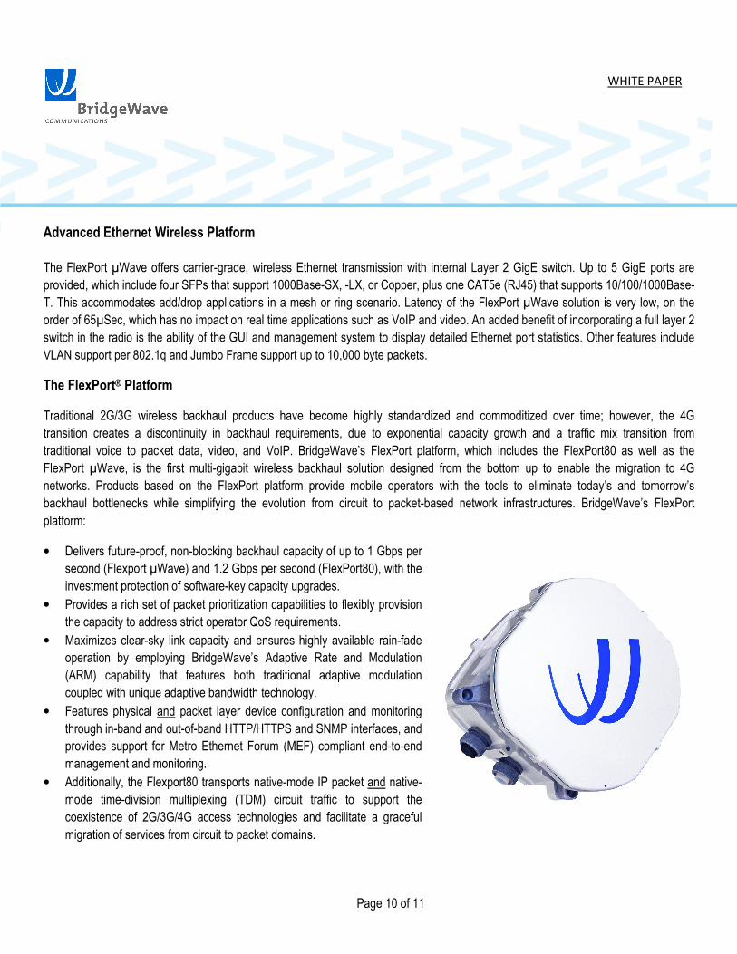
The FlexPort® Platform
Traditional 2G/3G wireless backhaul products have become highly standardized and commoditized over time; however, the 4G
transition creates a discontinuity in backhaul requirements, due to exponential capacity growth and a traffic mix transition from
traditional voice to packet data, video, and VoIP. BridgeWave’s FlexPort platform, which includes the FlexPort80 as well as the
FlexPort µWave, is the first multi-gigabit wireless backhaul solution designed from the bottom up to enable the migration to 4G
networks. Products based on the FlexPort platform provide mobile operators with the tools to eliminate today’s and tomorrow’s
backhaul bottlenecks while simplifying the evolution from circuit to packet-based network infrastructures. BridgeWave’s FlexPort
platform:
• Delivers future-proof, non-blocking backhaul capacity of up to 1 Gbps per
second (Flexport µWave) and 1.2 Gbps per second (FlexPort80), with the
investment protection of software-key capacity upgrades.
• Provides a rich set of packet prioritization capabilities to flexibly provision
the capacity to address strict operator QoS requirements.
• Maximizes clear-sky link capacity and ensures highly available rain-fade
operation by employing BridgeWave’s Adaptive Rate and Modulation
(ARM) capability that features both traditional adaptive modulation
coupled with unique adaptive bandwidth technology.
• Features physical and packet layer device configuration and monitoring
through in-band and out-of-band HTTP/HTTPS and SNMP interfaces, and
provides support for Metro Ethernet Forum (MEF) compliant end-to-end
management and monitoring.
• Additionally, the Flexport80 transports native-mode IP packet and native-
mode time-division multiplexing (TDM) circuit traffic to support the
coexistence of 2G/3G/4G access technologies and facilitate a graceful
migration of services from circuit to packet domains.

WHITE PAPER
Page 11 of 11
Backhaul Evolved
4G deployments offer the promise of a step-function in subscriber performance experience but come with the costs of major
architecture and capacity upgrades for operators. BridgeWave’s FlexPort® platform sets the new standard for 4G wireless backhaul
solutions, delivering future-proof multi-gigabit capacity and the tools that mobile operators need for next generation networks.
About BridgeWave Communications
Founded in 1999, BridgeWave Communications is the leading supplier of outdoor Gigabit wireless connectivity solutions. The
company's exclusive AdaptRate™ and AdaptPath™ technologies combined with its advanced Forward Error Correction capability
deliver the highest availability at the longest distances for full-rate gigabit links. BridgeWave's point-to-point wireless solutions are
widely deployed in mainstream enterprise and service provider network applications and are poised to play a key role in the migration
to 4G mobile network backhaul. With the introduction of FlexPort®, carriers and mobile operators have a true future-proof solution
providing migration from TDM-based networks to next generation IP-based networks with up to 1.2 Gbps capacity and carrier-class
Ethernet capabilities. With the largest installed base of GigE radios worldwide, BridgeWave delivers the highest levels of product
quality and reliability. For more information, visit www.bridgewave.com.
BridgeWave Communications, Inc. 3350 Thomas Rd. Santa Clara, CA. 95054 USA Ph: +1 (866) 577-6908; +1 (408) 567-6908 [email protected]
© 2010 BridgeWave Communications, Inc. All rights reserved. All other trademarks mentioned in this document or Web site are the property of their respective owners. Rev 2