WP-130 The Advantages of Row and Rack-Oriented Cooling ...
21
The Advantages of Row and Rack- Oriented Cooling Architectures for Data Centers White Paper #130 By Kevin Dunlap Neil Rasmussen
Transcript of WP-130 The Advantages of Row and Rack-Oriented Cooling ...

The Advantages of Row and Rack-Oriented Cooling Architectures for Data Centers
White Paper #130
By Kevin Dunlap Neil Rasmussen

2006 American Power Conversion. All rights reserved. No part of this publication may be used, reproduced, photocopied, transmitted, or stored in any retrieval system of any nature, without the written permission of the copyright owner. www.apc.com Rev 2006-0 2
Executive Summary Room cooling is an ineffective approach for next-generation data centers. Latest generation
high density and variable density IT equipment create conditions that room cooling was
never intended to address, resulting in cooling systems that are inefficient, unpredictable,
and low in power density. Row-oriented and rack-oriented cooling architectures have been
developed to address these problems. This paper contrasts room, row, and rack
architectures and shows why row-oriented cooling will emerge as the preferred solution for
most next generation data centers.

2006 American Power Conversion. All rights reserved. No part of this publication may be used, reproduced, photocopied, transmitted, or stored in any retrieval system of any nature, without the written permission of the copyright owner. www.apc.com Rev 2006-0 3
Introduction All of the electrical power delivered to the IT loads in a data center ends up as waste heat that must be
removed to prevent over temperature conditions. Virtually all IT equipment is air-cooled, that is, each piece
of IT equipment takes in ambient air and ejects waste heat into its exhaust air. Since a data center may
contain thousands of IT devices, the result is that there are thousands of hot airflow paths within the data
center that together represent the total waste heat output of the data center; waste heat that must be
removed. The purpose of the air conditioning system for the data center is to efficiently capture this complex
flow of waste heat and eject it from the room.
Room-based cooling is the historical method for accomplishing data center cooling. In this approach, one or
more air conditioning systems, working in parallel, push cool air into the data center while drawing out
warmer ambient air. The basic principle of this approach is that the air conditioners not only provide raw
cooling capacity, but they also serve as a large mixer, constantly stirring and mixing the air in the room to
bring it to a homogeneous average temperature, preventing hot-spots from occurring. This approach is
effective only as long as the power needed to mix the air is a small fraction of the total data center power
consumption. Simulation data and experience show that this system is effective when the average power
density in data is on the order of 1-2 kW per rack, translating to 323-753 W/m2 (30-70 W/ft2). Unfortunately,
the power densities of modern IT equipment are pushing peak power density to 20 kW per rack or more,
where simulation data and experience show that room-based cooling dependent on air mixing no longer
functions effectively.
To address this problem, new design approaches are emerging that focus on row or rack based cooling. In
these approaches the air conditioning systems are specifically integrated with rows of racks or individual
racks. This provides much better predictability, higher density, higher efficiency, and a number of other
benefits. In this paper, the various approaches are explained and contrasted. It will be shown that each of
the three approaches has an appropriate application, and in general a trend away from room based cooling
toward row based cooling should be expected for higher density applications.
Room, row, and rack based cooling architectures Every data center air conditioning system has two key functions: to provide the bulk cooling capacity, and to
distribute the air to the IT loads. The first function of providing bulk cooling capacity is the same for all
cooling architectures, namely, that the bulk cooling capacity of the air conditioning system in kilowatts must
exhaust the total power load (kW) of the IT equipment. The various technologies to provide this function are
the same whether the cooling system is designed at the room, row, or rack level. The major difference
between cooling architectures lies in how they perform the second critical function, distribution of air to the
loads. Unlike power distribution, where flow is constrained to wires and clearly visible as part of the design,
airflow is only crudely constrained by the room design and the actual air flow is not visible in implementation

2006 American Power Conversion. All rights reserved. No part of this publication may be used, reproduced, photocopied, transmitted, or stored in any retrieval system of any nature, without the written permission of the copyright owner. www.apc.com Rev 2006-0 4
and varies considerably between different installations. Controlling the airflow is the main objective of the
different cooling system design approaches.
The 3 basic architectures are shown in the generic floor plans depicted in Figure 1. In the figure, black
square boxes represent racks arranged in rows, and the blue arrows represent the logical association of the
CRAC units to the loads in the IT racks. The actual physical layout of the CRAC units may vary. In the room-
oriented architecture, the CRAC units are associated with the room; in the row level architecture the CRAC
units are associated with rows or groups, and with the rack level architecture CRAC units are assigned to
the individual racks.
Figure 1 – Floor plans showing the basic concept of room, row, and rack-oriented cooling architecture. Blue arrows indicate the relation of the primary cooling supply paths to the room.
Room Row Rack
A summary of the basic operating principles of each method are provided in the following sections:
Room-oriented architecture In room-oriented architecture, the CRAC units are associated with the room and operate concurrently to
address the total heat load of the room. A room-oriented architecture may consist of one or more air
conditioners supplying cool air completely unrestricted by ducts, dampers, vents, etc. or the supply and/or
return may be partially constrained by a raised floor system or overhead return plenum. For more
information see APC White Paper #55, “Air Distribution Architecture Options for Mission Critical Facilities”.
During design, the attention paid to the airflow typically varies greatly. For smaller rooms, racks are
sometimes placed in an unplanned arrangement, with no specific planned constraints to the airflow. For
larger more sophisticated installations, raised floors may be used to distribute air into well-planned hot-aisle /
cold aisle layouts for the express purpose of directing and aligning the airflow with the IT cabinets.

2006 American Power Conversion. All rights reserved. No part of this publication may be used, reproduced, photocopied, transmitted, or stored in any retrieval system of any nature, without the written permission of the copyright owner. www.apc.com Rev 2006-0 5
The room-oriented design is heavily affected by the unique constraints of the room, including the ceiling
height, the room shape, obstructions above and under the floor, rack layout, CRAC location, the distribution
of power among the IT loads, etc. The result is that performance prediction and performance uniformity are
poor, particularly as power density is increased. Therefore, complex computer simulations called
computational fluid dynamics (CFD) may be required to help understand the design performance of specific
installations. Furthermore, alterations such as IT equipment moves, adds, and changes may invalidate the
performance model and require further analysis and/or testing. In particular, the assurance of CRAC
redundancy becomes a very complicated analysis that is difficult to validate.
Another significant shortcoming of room-oriented architecture is that in many cases the full rated capacity of
the CRAC cannot be utilized. This condition is a result of room design and occurs when a significant fraction
of the air distribution pathways from the CRAC units bypass the IT loads and return directly to the CRAC.
This bypass air represents CRAC airflow that is not assisting with cooling of the loads; in essence a
decrease in overall cooling capacity. The result is that cooling requirements of the IT layout can exceed the
cooling capacity of the CRAC even when additional bulk cooling (kW) capacity of the CRAC is not fully
utilized. This problem is discussed in more detail in APC White Paper #49, “Avoidable Mistakes that
Compromise Cooling Performance in Data Centers and Network Rooms”.
Row-oriented architecture With a row-oriented architecture, the CRAC units are associated with a row and are assumed to be
dedicated to a row for design purposes. The CRAC units may be mounted among the IT racks, they may be
mounted overhead, or they may be mounted under the floor. Compared with the room-oriented architecture,
the airflow paths are shorter and more clearly defined. In addition, airflows are much more predictable, all of
the rated capacity of the CRAC can be utilized, and higher power density can be achieved.
The row-oriented architecture has a number of side benefits other than cooling performance. The reduction
in the airflow path length reduces the CRAC fan power required, increasing efficiency. This is not a minor
benefit, when we consider that in many lightly loaded data centers the CRAC fan power losses alone exceed
the total IT load power consumption.
A row-oriented design allows cooling capacity and redundancy to be targeted to the actual needs of specific
rows. For example, row-oriented architecture allows one row of racks to run high density applications such
as blade server, while another row satisfies lower power density applications such as communication
enclosures. Furthermore, N+1 or 2N redundancy can be targeted at specific rows.
A row-oriented architecture can be implemented without a raised floor. This increases the floor load bearing
capacity, reduces installation costs, eliminates the need for access ramps, and allows data centers to exist
in buildings that otherwise do not have the headroom to permit the installation of a sufficient raised floor.
This is particularly an issue for high density installations where a raised floor height of one meter or more is
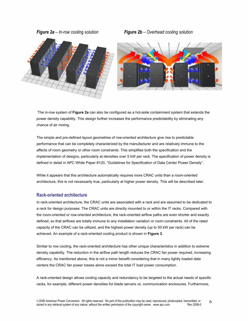
required. Examples of row-oriented cooling products are shown in Figures 2a and 2b.
2006 American Power Conversion. All rights reserved. No part of this publication may be used, reproduced, photocopied, transmitted, or stored in any retrieval system of any nature, without the written permission of the copyright owner. www.apc.com Rev 2006-0 6
Figure 2a – In-row cooling solution Figure 2b – Overhead cooling solution
The in-row system of Figure 2a can also be configured as a hot-aisle containment system that extends the
power density capability. This design further increases the performance predictability by eliminating any
chance of air mixing.
The simple and pre-defined layout geometries of row-oriented architecture give rise to predictable
performance that can be completely characterized by the manufacturer and are relatively immune to the
affects of room geometry or other room constraints. This simplifies both the specification and the
implementation of designs, particularly at densities over 5 kW per rack. The specification of power density is
defined in detail in APC White Paper #120, “Guidelines for Specification of Data Center Power Density”.
While it appears that this architecture automatically requires more CRAC units than a room-oriented
architecture, this is not necessarily true, particularly at higher power density. This will be described later.
Rack-oriented architecture In rack-oriented architecture, the CRAC units are associated with a rack and are assumed to be dedicated to
a rack for design purposes. The CRAC units are directly mounted to or within the IT racks. Compared with
the room-oriented or row-oriented architecture, the rack-oriented airflow paths are even shorter and exactly
defined, so that airflows are totally immune to any installation variation or room constraints. All of the rated
capacity of the CRAC can be utilized, and the highest power density (up to 50 kW per rack) can be
achieved. An example of a rack-oriented cooling product is shown in Figure 3.
Similar to row cooling, the rack-oriented architecture has other unique characteristics in addition to extreme
density capability. The reduction in the airflow path length reduces the CRAC fan power required, increasing
efficiency. As mentioned above, this is not a minor benefit considering that in many lightly loaded data
centers the CRAC fan power losses alone exceed the total IT load power consumption.
A rack-oriented design allows cooling capacity and redundancy to be targeted to the actual needs of specific
racks, for example, different power densities for blade servers vs. communication enclosures. Furthermore,

2006 American Power Conversion. All rights reserved. No part of this publication may be used, reproduced, photocopied, transmitted, or stored in any retrieval system of any nature, without the written permission of the copyright owner. www.apc.com Rev 2006-0 7
N+1 or 2N redundancy can be targeted to specific racks. By contrast, row-oriented architecture only allows
these characteristics to be specified at the row level, and room-oriented architecture only allows these
characteristics to be specified at the room level.
Figure 3 – Rack cooling solution with cooling completely internal to rack
The deterministic geometry of rack-oriented architecture gives rise to predictable performance that can be
completely characterized by the manufacturer and are totally immune to the affects of room geometry or
other room constraints. This allows simple specification of power density and design to implement the
specified density. The specification of power density is defined in detail in APC White Paper #120,
“Guidelines for Specification of Data Center Power Density”.
The principal drawback of this approach is that it requires a large number of air conditioning devices and
associated piping when compared to the other approaches, particularly at lower power density. This will be
quantified later in this paper.
Mixed architecture Nothing prevents the room, row, and rack architectures from being used together in the same installation. In
fact, there are many cases where mixed use is beneficial. Specifically, a data center operating with a broad
spectrum of power densities could benefit from a mix of all three types as shown in Figure 4:

2006 American Power Conversion. All rights reserved. No part of this publication may be used, reproduced, photocopied, transmitted, or stored in any retrieval system of any nature, without the written permission of the copyright owner. www.apc.com Rev 2006-0 8
Figure 4 – Floor layout of a system utilizing room, row, and rack-oriented architectures simultaneously
• Room-oriented: Supplying a room but primarily serving a low density area of mixed equipment such as
communication equipment, low density servers, and storage. Target: 1-3 kW per rack, 323-861 W/m2 (30-
80 W/ft2)
• Row-oriented: Supplying a high density or ultra-high density area with blade servers or 1U servers.
• Rack-oriented: Supplying isolated high density racks, or ultra-high density racks. Another effective use of row and rack-oriented architecture is for density upgrades within an existing low
density room-oriented design. In this case, small groups of racks within an existing data center are outfitted
with row or rack-oriented cooling systems. The row or rack cooling equipment effectively isolates the new
high density racks, making them essentially “thermally neutral” to the existing room-oriented cooling system.
In this way, high density loads can be added to an existing low density data center without modifying the
existing room-oriented cooling system. When deployed, this approach results in the same mixed architecture
depicted by Figure 4 above.
Hybrids There are additional cooling technologies available that have properties that defy categorization into the
three architectures defined above, and share features of each.
Ducted exhaust air scavenging systems capture exhaust air at the rack level and duct it directly back to a
room-oriented cooling system. This system has some of the benefits of a rack-oriented cooling system but
can integrate into an existing or planned room-oriented cooling system. An example of this equipment is
shown in Figure 5.
d
Row-oriented Rack-oriented
Room-oriented

2006 American Power Conversion. All rights reserved. No part of this publication may be used, reproduced, photocopied, transmitted, or stored in any retrieval system of any nature, without the written permission of the copyright owner. www.apc.com Rev 2006-0 9
Figure 5 – Rack level ducted exhaust into dropdown ceiling
Benefit comparison of cooling architectures To make effective decisions regarding choice of architecture for new data centers or upgrades, it is essential
to relate the performance characteristics of the architectures to practical issues that affect the design and
operation of real data centers. A survey of data center operators suggests that these issues can be
categorized into one of the following:
• Agility
• System availability
• Lifecycle costs (TCO)
• Serviceability
• Manageability
In this section, we review each of the above categories that users have identified, and focus on how the
alternative architectures address key cooling challenges. The highest priority challenges are listed first under
each category, and were determined by number of mentions combined priority expressed by the
respondents.

2006 American Power Conversion. All rights reserved. No part of this publication may be used, reproduced, photocopied, transmitted, or stored in any retrieval system of any nature, without the written permission of the copyright owner. www.apc.com Rev 2006-0 10
Agility challenges Data center users have identified the agility challenges shown in Table 1 as critical cooling-related issues.
The effectiveness of the different architectures in addressing these challenges is summarized as well.
Table 1 – Effectiveness of the room, row, and rack-oriented cooling architectures in addressing agility challenges. Best performance highlighted in blue.
Agility Challenges
Challenge Rack Row Room Plan for a power density that is increasing and unpredictable
Modular; deployable at rack level increments targeted at specific density
Modular; deployable at row level increments targeted at specific density
Complex to upgrade or adapt; typically built out in advance of requirement
Reduce the extensive engineering required for custom installations
Immune to room effects; rack layout may be completely arbitrary
Immune to room effects when rows laid out according to standard designs; configure with simple tools
Complex CFD analysis required which is different for every room
Adapt to ever-changing requirements or any power density
Rack cooling capacity that is not used cannot be used by other racks
Cooling capacity is well defined and can be shared across a group of racks
Any change may result in overheating; complex analysis required to assure redundancy and density are achieved
Allow for cooling capacity to be added to an existing operating space
New loads may be added that are completely isolated from the existing cooling system; limited to rack cooling capacity
New loads may be added that are completely isolated from the existing cooling system; each additional cooling system increases density for entire row
May require shutdown of existing cooling system; requires extensive engineering
Provide a highly flexible cooling deployment with minimal reconfiguration
Racks may need to be retrofit or IT equipment moved to accommodate new architecture
Requires the rack rows to be spaced to accommodate or changes to overhead infrastructure for new architecture
Floor tiles can be reconfigured quickly to change cooling distribution pattern for power densities <3 kW

2006 American Power Conversion. All rights reserved. No part of this publication may be used, reproduced, photocopied, transmitted, or stored in any retrieval system of any nature, without the written permission of the copyright owner. www.apc.com Rev 2006-0 11
Availability challenges Data center users have identified the availability challenges shown in Table 2 as critical cooling-related
issues. The effectiveness of the different architectures in addressing these challenges is summarized as
well.
Table 2 – Effectiveness of the room, row, and rack-oriented cooling architectures in addressing availability challenges. Best performance highlighted in blue.
Availability Challenges
Challenge Rack Row Room Eliminate hot spots Closely couples heat
removal with the heat generation to eliminate mixing The airflow is completely contained in the rack
Closely couples heat removal with the heat generation to minimize mixing
Supply and return paths promote mixing; engineered ductwork required to separate air streams
Assure redundancy when required
2N cooling capacity required for each rack; many rack cooling systems are not redundant capable
Utilizes shared N+1 capacity across common air return
Complex CFD analysis required to model failure modes; requires localized redundancy
Eliminate vertical temperature gradients at the face of the rack
Heat captured at the rear of the rack before mixing with cold supply air
Heat captured at the rear of the rack before mixing with cold supply air
Warm air may recirculate to front of rack as a result of insufficient heat removal or supply
Minimize the possibility of liquid leaks in the mission critical installation
Operates at warmer return temperatures to reduce or eliminate moisture removal and make-up sources. Rack targeted cooling requires additional piping and leakage points
Operates at warmer return temperatures to reduce or eliminate moisture removal and make-up sources
Mixed air return promotes the production of condensate and increases requirement for humidification
Minimize human error Standardized solutions are well documented and can be operated by any user
Standardized solutions are well documented and can be operated by any user
Uniquely engineered system requires a highly trained and specialized operator

2006 American Power Conversion. All rights reserved. No part of this publication may be used, reproduced, photocopied, transmitted, or stored in any retrieval system of any nature, without the written permission of the copyright owner. www.apc.com Rev 2006-0 12
Lifecycle cost challenges Data center users have identified the lifecycle cost challenges shown in Table 3 as high priority cooling-
related issues. The effectiveness of the different architectures in addressing these challenges is summarized
as well.
Table 3 – Effectiveness of the room, row, and rack-oriented cooling architectures in addressing lifecycle cost challenges. Best performance highlighted in blue.
Lifecycle Cost Challenges
Challenge Rack Row Room Optimize capital investment and available space
Dedicated system for each rack may result in oversizing and wasted capacity
Ability to match the cooling requirements to a much higher percentage of installed capacity
System performance is difficult to predict, resulting in frequent oversizing
Accelerate speed of deployment
Pre-engineered system that eliminates or reduces planning and engineering
Pre-engineered system that eliminates or reduces planning and engineering
Requires unique engineering that may exceed the organizational demand
Lower the cost of service contracts
Standardized components reduce service time and facilitate the ability for user serviceability. Likely higher number of units with 1:1 ratio to IT rack enclosures.
Standardized components reduce service time and facilitates the ability for user serviceability
Specialized service contracts required for custom components
Quantify the return on investment for cooling system improvements
Standardized components for accurate measurement of system performance
Standardized components for accurate measurement of system performance
Customer engineered solutions makes system performance difficult to predict
Maximize the operational efficiency by matching capacity to load
Cooling system will likely be oversized and full potential not realized.
Right-sized cooling capacity to the cooling load matching heat load to installed capacity
Air delivery dictates oversized capacity; pressure requirements for under floor delivery are a function of the room size and floor depth.
2006 American Power Conversion. All rights reserved. No part of this publication may be used, reproduced, photocopied, transmitted, or stored in any retrieval system of any nature, without the written permission of the copyright owner. www.apc.com Rev 2006-0 13
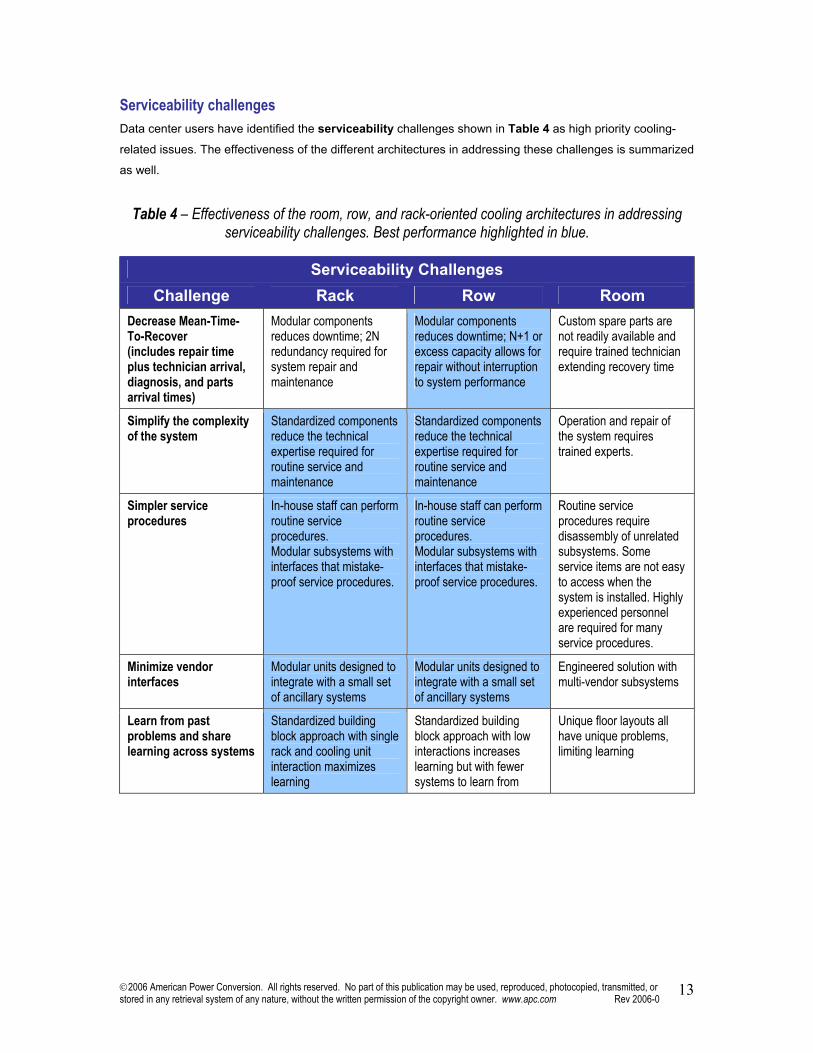
Serviceability challenges Data center users have identified the serviceability challenges shown in Table 4 as high priority cooling-
related issues. The effectiveness of the different architectures in addressing these challenges is summarized
as well.
Table 4 – Effectiveness of the room, row, and rack-oriented cooling architectures in addressing serviceability challenges. Best performance highlighted in blue.
Serviceability Challenges
Challenge Rack Row Room Decrease Mean-Time-To-Recover (includes repair time plus technician arrival, diagnosis, and parts arrival times)
Modular components reduces downtime; 2N redundancy required for system repair and maintenance
Modular components reduces downtime; N+1 or excess capacity allows for repair without interruption to system performance
Custom spare parts are not readily available and require trained technician extending recovery time
Simplify the complexity of the system
Standardized components reduce the technical expertise required for routine service and maintenance
Standardized components reduce the technical expertise required for routine service and maintenance
Operation and repair of the system requires trained experts.
Simpler service procedures
In-house staff can perform routine service procedures. Modular subsystems with interfaces that mistake-proof service procedures.
In-house staff can perform routine service procedures. Modular subsystems with interfaces that mistake-proof service procedures.
Routine service procedures require disassembly of unrelated subsystems. Some service items are not easy to access when the system is installed. Highly experienced personnel are required for many service procedures.
Minimize vendor interfaces
Modular units designed to integrate with a small set of ancillary systems
Modular units designed to integrate with a small set of ancillary systems
Engineered solution with multi-vendor subsystems
Learn from past problems and share learning across systems
Standardized building block approach with single rack and cooling unit interaction maximizes learning
Standardized building block approach with low interactions increases learning but with fewer systems to learn from
Unique floor layouts all have unique problems, limiting learning

2006 American Power Conversion. All rights reserved. No part of this publication may be used, reproduced, photocopied, transmitted, or stored in any retrieval system of any nature, without the written permission of the copyright owner. www.apc.com Rev 2006-0 14
Manageability challenges Data center users have identified the manageability challenges shown in Table 5 as important cooling-
related issues. The effectiveness of the different architectures in addressing these challenges is summarized
as well.
Table 5 – Effectiveness of the room, row, and rack-oriented cooling architectures in addressing
manageability challenges. Best performance highlighted in blue.
Manageability Challenges Challenge Rack Row Room
System menu must be clear and provide ease of navigation
Low option configuration allows user to navigate through menu interface quickly
Low option configuration allows user to navigate through menu interface quickly
Highly configurable system complicates the menu structure. Requires advanced service training
Provide predictive failure analysis
Ability to provide real-time models of current and future performance.
Ability to provide near real-time models of current or future performance as a result of limited control effects
Virtually impossible to provide real-time models of current or future performance due to room-specific effects
Provide, aggregate, and summarize cooling performance data
Cooling capacity information at the rack level is determined and available in real time
Cooling capacity information at the row level is determined and available in real time. Rack level information can be effectively estimated.
Cooling capacity information is not available at the rack or row level
Summary and analysis A review and analysis of the above comparison tables suggests the following conclusions:
• The modular rack-oriented architecture is the most flexible, fast to implement, and achieves extreme
density, but at the cost of additional expense.
• Room-oriented architecture is inflexible, time consuming to implement, and performs poorly at higher
density but has cost and simplicity advantages at lower density.
• The modular row-oriented architecture provides many of the flexibility, speed, and density advantages of
the rack-oriented approach, but with a cost similar to the room-oriented architecture.
These issues are explained in additional detail in the following sections.
Special Issues There are a number of practical issues that require additional explanation and discussion regarding the
architectures. These are discussed in this section.

2006 American Power Conversion. All rights reserved. No part of this publication may be used, reproduced, photocopied, transmitted, or stored in any retrieval system of any nature, without the written permission of the copyright owner. www.apc.com Rev 2006-0 15
Capacity Utilization Most users naturally assume that if they have 500 kW of cooling units installed, they can install and cool 500
kW of IT loads. This is simply not the case. While a group of air conditioning units taken together may have
in total the claimed capacity, this does not mean that they are able to deliver this cooling to the load. The
fraction of the actual capacity that can be obtained in the real world cooling IT loads is called the “usable
capacity”. Any time the usable capacity is less than 100%, the CRAC systems must be oversized with the
attendant increases in cost, space, and maintenance. The three cooling system architectures have
dramatically different behavior in this regard, as explained in the following sections and summarized in
Figure 5.
Figure 5 – Usable air conditioner capacity as a function of average
rack power density for the three cooling architectures
0%
20%
40%
60%
80%
100%
1 2 3 4 5 6 7 8 9 10 11 12 13 14 15 16 17 18 19 20 21 22 23 24 25
Average Per-Rack Power Density (kW)
Usa
ble
CR
AC
Cap
acity
row-oriented cooling
rack-oriented cooling
rooom-oriented cooling
The figure shows how the usable capacity varies for the three different cooling architectures as a function of
rack power density. This model assumed a peak-to-average rack power density of 1.5:1, an N+1 cooling
redundancy requirement, a maximum row length of 10 racks, a room CRAC rating of 100 kW per unit, a row
CRAC rating of 25 kW per unit, and a rack CRAC rating equal to the peak power density requirement.
Different assumptions will generate different results, but the general pattern of the data is not affected.
Note that in this case “usable capacity” refers to the CRAC units only, given their direct interaction with the
IT equipment. The outdoor heat rejection systems may be operating at 100% usable capacity for all three
architectures. Therefore the costs associated with the loss of capacity should only be applied to the indoor
CRAC systems.
The usable capacity in a rack-oriented architecture is typically significantly less than 100%. In this
architecture, each rack has a dedicated air conditioner and therefore dedicated capacity. Whenever the
actual load in a rack is less than the rated capacity of that rack, the remainder of the capacity of that rack is
2006 American Power Conversion. All rights reserved. No part of this publication may be used, reproduced, photocopied, transmitted, or stored in any retrieval system of any nature, without the written permission of the copyright owner. www.apc.com Rev 2006-0 16
not utilized, and furthermore cannot be utilized by any other rack. For example, if a rack has 10 kW of
cooling but only a 6 kW IT load, the rack has 4 kW of stranded capacity that cannot be used by any other
rack. This stranded capacity cannot be borrowed by neighboring racks for redundancy maintenance, or any
other purpose. Since real-world racks vary significantly in power density, usable capacity may be 50% or
even lower of the rated capacity. Figure 5 shows the variation of usable capacity as a function of power
density for a rack-oriented architecture. The assumption of redundancy strongly impacts the usable capacity
in a rack-oriented architecture because two fully rated CRACs are needed for every rack; for a non-
redundant system the utilization would double in this architecture. Note that utilization is independent of
power density for this architecture.
The usable capacity in a room-oriented architecture appears on the surface to be 100%, because it appears
that all the capacity is pooled and sharable at the room level. In fact, at very low power densities such as 1-2
kW per rack, this is a reasonable assumption as shown in the Figure 5. However, this assumption breaks
down quite dramatically as the power density increases. This loss of capacity is due to the inability of the
system to deliver the required cool air to the load. The result is that the system must be oversized compared
with the load, resulting in a reduction in the effective usable capacity. The lack of predictability of the room-
oriented architecture creates a practical cutoff of around 6 kW per rack as shown in Figure 5.
Row-oriented offers the highest usable capacity across the broadest power density range. Due to the close
coupling of the CRAC units to the load, all of the capacity can be delivered to the load up to power densities
on the order of 25 kW, or approximately 4X the practical density capacity of room-oriented architecture. In
addition, CRAC units can share cooling with nearby racks, which reduces the stranded capacity problem
discussed earlier which is associated with rack-oriented architecture. However, the usable capacity of row-
oriented architecture falls at very low power densities, because air conditioning units must be assigned to
every row no matter how low the density becomes. The unusual jagged nature of the usable capacity curve
for the row-oriented architecture is due to quantization effects, due to finite row lengths combined with the
need to assign CRAC units to specific rows and the lack of fractional sizes for the CRAC units. If the row
lengths were unlimited this would become a smooth curve.
Humidification One of the key functions of a computer room air conditioning system is to maintain humidity to reduce the
possibility of damaging static discharge. Often this function is integrated into the air conditioning unit. In
architectures that may increase the number of air conditioning units, a natural question that arises is whether
the number of humidification devices must also increase. This is of particular concern because
humidification units have water lines and are normally a relatively high maintenance item.
A careful analysis of this problem shows that the integration of humidification equipment into air conditioners
as is commonly done is fundamentally flawed, and that humidification should be separate from air
conditioning equipment and done at the room level. This is for three reasons:

2006 American Power Conversion. All rights reserved. No part of this publication may be used, reproduced, photocopied, transmitted, or stored in any retrieval system of any nature, without the written permission of the copyright owner. www.apc.com Rev 2006-0 17
• Higher density installations may have a large number of CRAC units no matter which architecture is
chosen; there is no technical need to have as many humidification units and there are many practical
disadvantages, such as maintenance, of having large numbers of them.
• When a room has a number of humidifiers it is difficult to coordinate their operation, resulting in a waste
of water and electricity.
• Cold air can accommodate less moisture and attempting to force moisture into the cold air output stream
of an air conditioner is inefficient or not possible depending on saturation.
A more complete discussion of this subject is contained in APC White Paper #133, “Humidification Systems:
Reducing Energy Costs In IT Environments”.
Electrical Efficiency Electrical costs are becoming a larger fraction of total operating costs, due to increasing electric rates, the
increase in electrical power required per server, and the increase of power density. While the dependency of
electrical costs on electric rates and server power is well understood, the affect of power density on
electrical costs is not generally considered. Density drives up electrical costs because it drives down the
efficiency of conventional air conditioning systems dramatically. Figure 6 illustrates the effect of power
density on annual electrical costs for the three cooling architectures.
Figure 6 – Annual CRAC electrical costs per megawatt of IT load
as a function of average rack power density for the three cooling architectures
$0
$50$100
$150$200
$250$300
$350
1 2 3 4 5 6 7 8 9 10 11 12 13 14 15 16 17 18 19 20 21 22 23 24 25
Average Per-Rack Power Density (kW)
Ann
ual E
lect
rica
l Cos
t (k$
)
row-oriented cooling
room-oriented cooling
rack-oriented cooling
In the model above, it is assumed that the usable CRAC capacity declines as shown in the prior Figure 5.
An N+1 design is assumed, along with the other assumptions of Figure 5. The electrical rate is assumed to
be $0.12 per kWhr. Also, the system is assumed to be operated at its rated value (100% loaded). The affect
of partial loading is significant and discussed below.

2006 American Power Conversion. All rights reserved. No part of this publication may be used, reproduced, photocopied, transmitted, or stored in any retrieval system of any nature, without the written permission of the copyright owner. www.apc.com Rev 2006-0 18
Note the costs in Figure 6 are for the CRAC unit only. The total air conditioner costs would include the
chiller plant costs as well, which are substantial but do not vary greatly between the three architectures.
The electrical costs are consistently low for the rack-oriented architecture, because the CRAC units are
closely coupled to the load, and sized to the load. Unnecessary airflow is avoided.
The electrical costs for a room-oriented architecture are quite low at low power densities, but degrade
dramatically as the density passes about 3 kW per rack average. Essentially, this is due to the need to move
more air over larger distances, and due to the need for the CRAC units to consume power to stir or mix the
air within the room to prevent hotspots.
The electrical costs associated with row-oriented architecture are poor at very low densities, but improve
dramatically at higher densities. Row-oriented design has a penalty at light density due to the need to have
CRAC units assigned to every row, even when the load is very light. Furthermore, these units have electrical
loss even when operated well below their rated capacity. However, row-oriented design has the best
efficiency and lowest electrical costs as the density increases. This is because the CRAC units are well
coupled to the IT loads, the usable CRAC capacity is sustained at high density, and a redundant CRAC unit
can support more than one rack.
Water or other heat transport piping near IT equipment Research shows that users are very concerned with water or refrigerant piping co-located with IT equipment.
This concern is not with the piping itself, but rather the possibility of leakage of fluids onto IT equipment, with
attendant downtime and/or damage.
High density data centers with multiple air conditioners are mainly chilled water designs and this trend is
expected to continue due to environmental and cost concerns. Although refrigerants that have less
possibility of damaging IT equipment exist, they are a more costly alternative to water for each of the cooling
architectures. Room-oriented architecture also permits the additional option of locating the CRAC units
outside of the data center and ducting in only air.
For higher density, the heat carrying capability of air is a limitation and coolant will need to enter the data
center. Recent advances in piping technology permit water transport into data centers with greatly improved
reliability and dramatically reduced chance of leakage. This subject is discussed in more detail in APC White
Paper #131, “Improved chilled water piping distribution methodology for Data Centers”.
Location The location of an air conditioning unit can have a dramatic effect on the system performance.
In the case of rack-oriented architecture, this problem of performance predictability is completely eliminated
since the exact location of the air conditioner to the target load is determined. The benefit is that the cooling
performance can be completely characterized in advance. If a phased deployment is part of the system
2006 American Power Conversion. All rights reserved. No part of this publication may be used, reproduced, photocopied, transmitted, or stored in any retrieval system of any nature, without the written permission of the copyright owner. www.apc.com Rev 2006-0 19
design, the location of future air conditioning units requires little planning or forethought, being automatically
deployed with each rack.
In the case of room-oriented cooling architecture, this situation changes dramatically. The location of air
conditioning units has infinite possibilities, and the system cooling performance is greatly affected by air
conditioner location. Furthermore, the most effective locations may not be feasible, due to physical
properties of the room including doorways, windows, ramps, inaccessibility of piping. The result is typically a
sub-optimal design even when considerable amounts of engineering are applied. In addition, the logistics of
installing room-oriented air conditioners typically require that they be placed into the room in advance
comprehending all future IT deployment phases. Since the exact layout of future IT phases may not be
known, the locations of the air conditioners are often grossly ineffective.
Row-oriented cooling architecture depends on simple design rules to locate air conditioners. The quantity
and locations of row-oriented air conditioners are determined by rules that have been established through
simulation and testing. Naturally this includes ensuring that the air conditioners are sufficiently sized to the
row density specification. In addition there are other rules, such as avoiding row end locations, which
maximize the performance and capacity of the system. During future deployments, some location flexibility is
retained up until the time of deployment, where the deployed values of average or peak-to-average rack
power density of the row can be used to establish the quantity and locations of air conditioners in a just-in-
time process.
Although the row-oriented architecture does not have quite the location and planning simplicity of the rack-
oriented approach, it is much more flexible than the room-oriented approach. The row-oriented architecture
achieves most of the flexibility and power density capability of the rack-oriented approach, but using a much
smaller footprint and much lower cost.
Redundancy Redundancy is necessary in cooling systems to permit maintenance of live systems and to ensure the
survival of the data center mission if an air conditioning device fails. Power systems often use dual path
feeds to IT systems to assure redundancy. This is because the power cords and connections themselves
represent a potential single point of failure. In the case of cooling, N+1 designs are common instead of dual
path approaches because the common air distribution paths, being simply open air around the rack, have a
very low probability of failure. The idea here is that if the system requires four CRAC units, the addition of a
5th to the system will allow any one of the units to fail and the total cooling load will be satisfied. Hence the
name “N+1” redundancy. For higher power densities this simple concept of redundancy breaks down. The
way redundancy is provided is different for the three cooling architectures as explained below:
For rack-oriented architecture, there is no sharing of cooling between racks, and no common distribution
path for air. Therefore, the only way to achieve redundancy is to provide a full 2N dual path CRAC system
for each rack: essentially 2 CRAC systems per rack. This is a severe penalty when compared with the
2006 American Power Conversion. All rights reserved. No part of this publication may be used, reproduced, photocopied, transmitted, or stored in any retrieval system of any nature, without the written permission of the copyright owner. www.apc.com Rev 2006-0 20
alternative approaches. However, for isolated high density racks this is very effective as the redundancy is
completely determined and predictable and independent of any other CRAC systems.
For room-oriented architecture, the room itself is supposed to be a common air supply path to all the IT
loads. In principle, this allows redundancy to be provided by introducing a single additional CRAC,
independent of the size of the room. This is the case for very low densities, and gives this approach a cost
advantage at low densities. However, at higher densities the ability of a particular CRAC to make up for the
loss of another is strongly affected by room geometry. For example, the air distribution pattern of a specific
CRAC cannot be replaced by a backup CRAC unit that is remotely located from the failed unit. The result is
that the number of additional CRAC units that are required to establish redundancy increases from the
single additional unit required at low densities to a doubling of CRAC units at densities greater than 10 kW
per rack.
Row-oriented architecture provides redundancy at the row level. This requires an additional or N+1 CRAC
unit for each row. Even though the row CRAC units are smaller and less expensive than room units, this is a
significant penalty at light loads of 1-2 kW per rack. However, for higher density this penalty is eliminated
and the N+1 approach is sustained up to 25 kW per rack. This is a major advantage when compared with
either room or rack-oriented designs, which both trend to 2N at higher densities. The ability to deliver
redundancy in high density situations with fewer additional CRAC units is a key benefit of the row-oriented
architecture and provides it a significant total cost of ownership (TCO) advantage.
Conclusion The conventional legacy approach to data center cooling using room-oriented architecture has technical and
practical limitations in next generation data centers. The need of next generation data centers to adapt to
changing requirements, to reliably support high and variable power density, and to reduce electrical power
consumption and other operating costs have directly led to the development of row and rack-oriented
cooling architectures. These two architectures are more successful at addressing these needs, particularly
at operating densities of 3 kW per rack or greater. The legacy room-oriented approach has served the
industry well, and remains an effective and practical alternative for lower density installations and those
applications where IT technology changes are minimal.
Row and rack-oriented cooling architecture provides the flexibility, predictability, scalability, reduced
electrical power consumption, reduced TCO, and optimum availability that next-generations data centers
require. Users should expect that many new product offerings from suppliers will utilize these approaches.
It is expected that many data centers will utilize a mixture of the three cooling architectures. Rack-oriented
cooling will find application in situations where extreme densities, high granularity of deployment, or
unstructured layout are the key drivers. Room-oriented cooling will remain an effective approach for low
density applications and applications where change is infrequent. For most users with newer high density

2006 American Power Conversion. All rights reserved. No part of this publication may be used, reproduced, photocopied, transmitted, or stored in any retrieval system of any nature, without the written permission of the copyright owner. www.apc.com Rev 2006-0 21
server technologies, row-oriented cooling will provide the best balance of high predictability, high power
density, and adaptability, at the best overall TCO.
About the Authors: Kevin Dunlap is the Product Line Manager for Modular/High Density Cooling Solutions at American Power
Conversion (APC). APC is a global leader in the development of precision power system technologies and
one of the world's largest providers of equipment that serves the network-critical physical infrastructure.
Involved with the power management industry since 1994, Kevin previously worked for Systems
Enhancement Corp., a provider of power management hardware and software, which APC acquired in 1997.
Following the acquisition, Kevin joined APC as a Product Manager for management cards and then
precision cooling solutions following the acquisition of Airflow Company in 2000.
Kevin has participated on numerous power management and cooling panels, as well as on industry
consortiums and ASHRAE committees for thermal management and energy efficient economizers.
Neil Rasmussen is a founder and the Chief Technical Officer of American Power Conversion. At APC, Neil
directs the world’s largest R&D budget devoted to power, cooling, and rack infrastructure for critical
networks, with principal product development centers in Massachusetts, Missouri, Denmark, Rhode Island,
Taiwan, and Ireland. Neil is currently leading the effort at APC to develop modular scalable data center
infrastructure solutions and is the principal architect of APC’s InfraStruXure system.
Prior to founding APC in 1981, Neil received his Bachelors and Masters degrees from MIT in electrical
engineering where he did his thesis on the analysis of a 200MW power supply for a Tokamak Fusion
reactor. From 1979 to 1981 he worked at MIT Lincoln Laboratories on flywheel energy storage systems and
solar electric power systems.