Worley Parsons Hvac Specifications1
66
Doc. No. 0435-JH0902-00-PP-RFQ-0010 ANNEXURE B TECHNICAL SPECIFICATION – HVAC
-
Upload
psn1234567890 -
Category
Documents
-
view
141 -
download
10
description
sew
Transcript of Worley Parsons Hvac Specifications1
Doc. No. 0435-JH0902-00-PP-RFQ-0010
ANNEXURE B
TECHNICAL SPECIFICATION – HVAC
HINDUSTAN PETROLEUM CORPORATION LIMITED (HPCL)
Page 1 of 13
Guru Gobind Singh Refinery Products Evacuation Project (GGSRPEP)
Raman Mandi- Bahadurgarh and Raman Mandi- Bhatinda Multiproduct Pipeline
BASIS OF DESIGN FOR HVAC
0435-JH0902-10-HV-BOD-0001 03.Sept-09
Sanghi Oxygen Compound 1, Mahal Industrial Estate Mahakali Caves Road Andheri (East), Mumbai - 400 093 India Phone: +91-22-67818000 Fax : +91-22-67818080 www.worleyparsons.com
© Copyright 2009 WorleyParsons
HINDUSTAN PETROLEUM CORPORATION LIMITED (HPCL)
HPCL GURU GOBIND SINGH REFINERY PRODUCTS EVACUATION PROJECT (GGSRPEP)
BASIS OF DESIGN FOR HVAC
Page 2 of 13
SYNOPSIS
Disclaimer
This report has been prepared on behalf of and for the exclusive use of Hindustan Petroleum
Corporation Limited (HPCL), and is subject to and issued in accordance with the agreement
between Hindustan Petroleum Corporation Limited (HPCL) and WorleyParsons. WorleyParsons
accepts no liability or responsibility whatsoever for it in respect of any use of or HPCL upon this
report by any third party.
Copying this report without the permission of Hindustan Petroleum Corporation Limited (HPCL) or
WorleyParsons is not permitted.
PROJECT 435/JH0902- HPCL GURU GOBIND SINGH REFINERY PRODUCTS EVACUATION PROJECT (GGSRPEP)
REV DESCRIPTION ORIG REVIEW WORLEY- PARSONS APPROVAL
DATE CLIENT APPROVAL
DATE
A Issued for DIC / SQC
Arya Sarkar
Sameer Ishwad
Jeremy Wallace
N/A
B Issued For Review
Arya Sarkar
Sameer Ishwad
Jeremy Wallace
21-July-09
N/A
C Issued For Tender
Arya Sarkar
Sameer Ishwad
KMN Pillai
03.Sept-09
HINDUSTAN PETROLEUM CORPORATION LIMITED (HPCL)
HPCL GURU GOBIND SINGH REFINERY PRODUCTS EVACUATION PROJECT (GGSRPEP)
BASIS OF DESIGN FOR HVAC
Page 3 of 13
TABLE OF CONTENT
1.0 Scope ....................................................................................................................................4
2.0 Abbreviations.........................................................................................................................4
3.0 Codes & Standards ...............................................................................................................4
4.0 Engineering Data...................................................................................................................8
5.0 Design Requirements ............................................................................................................9

HINDUSTAN PETROLEUM CORPORATION LIMITED (HPCL)
HPCL GURU GOBIND SINGH REFINERY PRODUCTS EVACUATION PROJECT (GGSRPEP)
BASIS OF DESIGN FOR HVAC
Page 4 of 13
1.0 Scope
The purpose of this document is to define the Basis of Design for HVAC discipline for carrying out the
Detailed Engineering for HPCL-GGSRPEP, Project. This document covers the requirements for new
equipment related to HVAC for HPCL-GGSRPEP, Project.
2.0 Abbreviations
ADC Air Diffusion Council
AMCA Air Moving and Control Association
ARI Air conditioning and Refrigeration Institute
ASHRAE American Society of Heating, Refrigerating and Air conditioning Engineers
ASTM American Society for Testing and Materials
HVAC Heating, Ventilating and Air Conditioning
ISO International Organization for Standardization
NEBB National Environmental Balancing Bureau
NEMA National Electrical Manufacturers Association
NFPA National Fire Protection Association
RMA Rubber Manufacturers Association
SMACNA Sheet Metal and Air Conditioning Contractors National Association
UL Underwriters Laboratories, Inc.
WP WorleyParsons
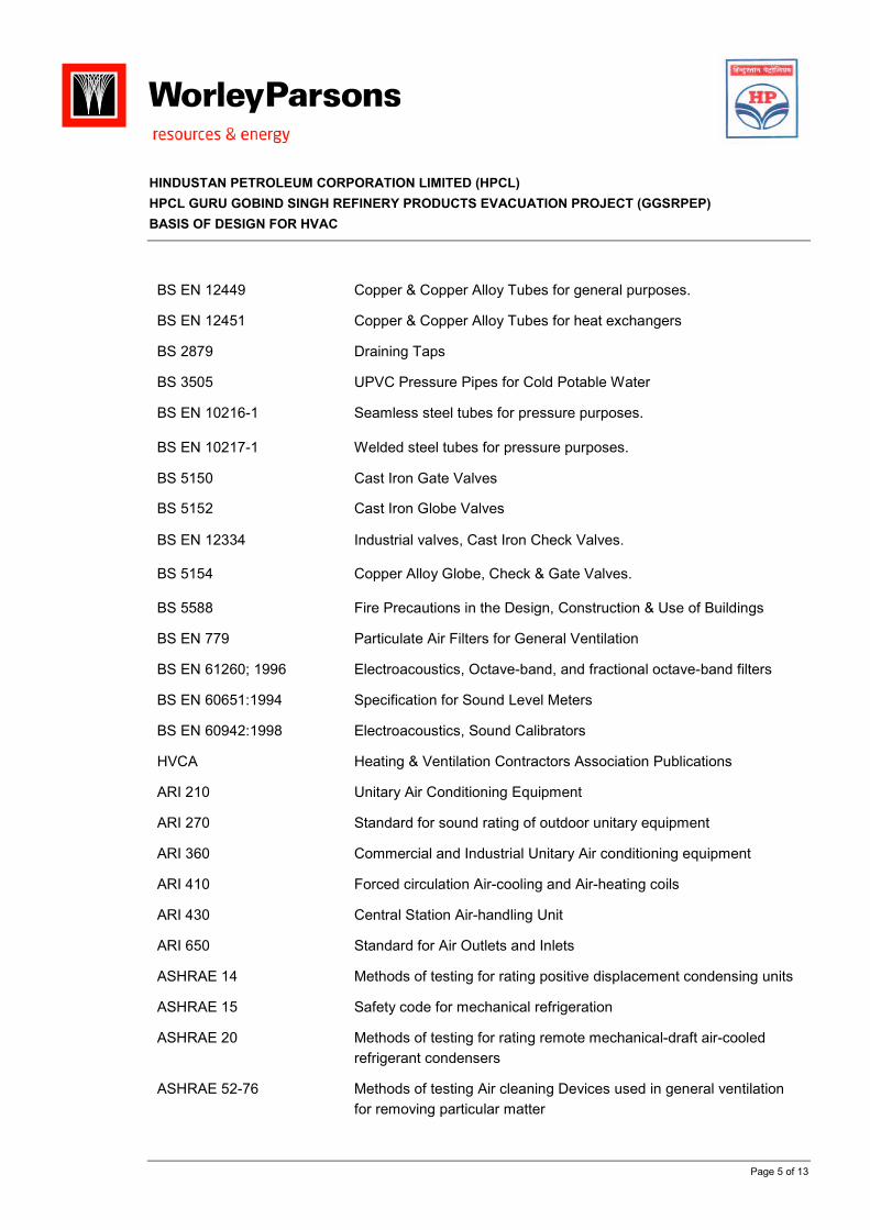
3.0 Codes & Standards
BS 759 Valves, Gauges & Other Safety Fittings.
BS 1387 Steel Tubes.
BS EN 1057 Copper & Copper Alloy Tubes for heating application.
HINDUSTAN PETROLEUM CORPORATION LIMITED (HPCL)
HPCL GURU GOBIND SINGH REFINERY PRODUCTS EVACUATION PROJECT (GGSRPEP)
BASIS OF DESIGN FOR HVAC
Page 5 of 13
BS EN 12449 Copper & Copper Alloy Tubes for general purposes.
BS EN 12451 Copper & Copper Alloy Tubes for heat exchangers
BS 2879 Draining Taps
BS 3505 UPVC Pressure Pipes for Cold Potable Water
BS EN 10216-1 Seamless steel tubes for pressure purposes.
BS EN 10217-1 Welded steel tubes for pressure purposes.
BS 5150 Cast Iron Gate Valves
BS 5152 Cast Iron Globe Valves
BS EN 12334 Industrial valves, Cast Iron Check Valves.
BS 5154 Copper Alloy Globe, Check & Gate Valves.
BS 5588 Fire Precautions in the Design, Construction & Use of Buildings
BS EN 779 Particulate Air Filters for General Ventilation
BS EN 61260; 1996 Electroacoustics, Octave-band, and fractional octave-band filters
BS EN 60651:1994 Specification for Sound Level Meters
BS EN 60942:1998 Electroacoustics, Sound Calibrators
HVCA Heating & Ventilation Contractors Association Publications
ARI 210 Unitary Air Conditioning Equipment
ARI 270 Standard for sound rating of outdoor unitary equipment
ARI 360 Commercial and Industrial Unitary Air conditioning equipment
ARI 410 Forced circulation Air-cooling and Air-heating coils
ARI 430 Central Station Air-handling Unit
ARI 650 Standard for Air Outlets and Inlets
ASHRAE 14 Methods of testing for rating positive displacement condensing units
ASHRAE 15 Safety code for mechanical refrigeration
ASHRAE 20 Methods of testing for rating remote mechanical-draft air-cooled
refrigerant condensers
ASHRAE 52-76 Methods of testing Air cleaning Devices used in general ventilation
for removing particular matter
HINDUSTAN PETROLEUM CORPORATION LIMITED (HPCL)
HPCL GURU GOBIND SINGH REFINERY PRODUCTS EVACUATION PROJECT (GGSRPEP)
BASIS OF DESIGN FOR HVAC
Page 6 of 13
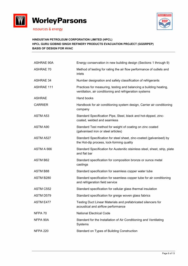
ASHRAE 90A Energy conservation in new building design (Sections 1 through 9)
ASHRAE 70 Method of testing for rating the air flow performance of outlets and
inlets
ASHRAE 34 Number designation and safety classification of refrigerants
ASHRAE 111 Practices for measuring, testing and balancing a building heating,
ventilation, air conditioning and refrigeration systems
ASHRAE Hand books
CARRIER Handbook for air conditioning system design, Carrier air conditioning
company
ASTM A53 Standard Specification Pipe, Steel, black and hot-dipped, zinc-
coated, welded and seamless
ASTM A90 Standard Test method for weight of coating on zinc coated
(galvanised iron or steel articles)
ASTM A527 Standard Specification for steel sheet, zinc-coated (galvanised) by
the Hot-dip process, lock-forming quality
ASTM A 666 Standard Specification for Austenitic stainless steel, sheet, strip, plate
and flat bar
ASTM B62 Standard specification for composition bronze or ounce metal
castings
ASTM B88 Standard specification for seamless copper water tube
ASTM B280 Standard specification for seamless copper tube for air conditioning
and refrigeration field service
ASTM C552 Standard specification for cellular glass thermal insulation
ASTM D579 Standard specification for greige woven glass fabrics
ASTM E477 Testing Duct Linear Materials and prefabricated silencers for
acoustical and airflow performance
NFPA 70 National Electrical Code
NFPA 90A Standard for the Installation of Air Conditioning and Ventilating
Systems
NFPA 220 Standard on Types of Building Construction
HINDUSTAN PETROLEUM CORPORATION LIMITED (HPCL)
HPCL GURU GOBIND SINGH REFINERY PRODUCTS EVACUATION PROJECT (GGSRPEP)
BASIS OF DESIGN FOR HVAC
Page 7 of 13
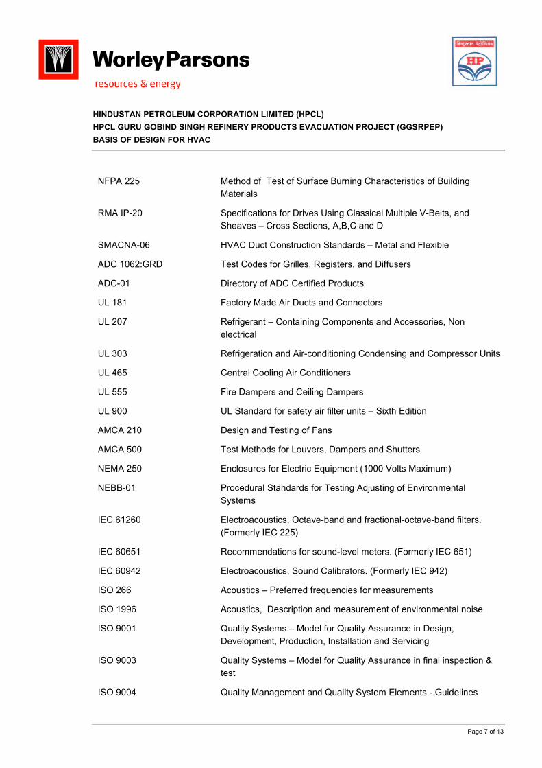
NFPA 225 Method of Test of Surface Burning Characteristics of Building
Materials
RMA IP-20 Specifications for Drives Using Classical Multiple V-Belts, and
Sheaves – Cross Sections, A,B,C and D
SMACNA-06 HVAC Duct Construction Standards – Metal and Flexible
ADC 1062:GRD Test Codes for Grilles, Registers, and Diffusers
ADC-01 Directory of ADC Certified Products
UL 181 Factory Made Air Ducts and Connectors
UL 207 Refrigerant – Containing Components and Accessories, Non
electrical
UL 303 Refrigeration and Air-conditioning Condensing and Compressor Units
UL 465 Central Cooling Air Conditioners
UL 555 Fire Dampers and Ceiling Dampers
UL 900 UL Standard for safety air filter units – Sixth Edition
AMCA 210 Design and Testing of Fans
AMCA 500 Test Methods for Louvers, Dampers and Shutters
NEMA 250 Enclosures for Electric Equipment (1000 Volts Maximum)
NEBB-01 Procedural Standards for Testing Adjusting of Environmental
Systems
IEC 61260 Electroacoustics, Octave-band and fractional-octave-band filters.
(Formerly IEC 225)
IEC 60651 Recommendations for sound-level meters. (Formerly IEC 651)
IEC 60942 Electroacoustics, Sound Calibrators. (Formerly IEC 942)
ISO 266 Acoustics – Preferred frequencies for measurements
ISO 1996 Acoustics, Description and measurement of environmental noise
ISO 9001 Quality Systems – Model for Quality Assurance in Design,
Development, Production, Installation and Servicing
ISO 9003 Quality Systems – Model for Quality Assurance in final inspection &
test
ISO 9004 Quality Management and Quality System Elements - Guidelines

HINDUSTAN PETROLEUM CORPORATION LIMITED (HPCL)
HPCL GURU GOBIND SINGH REFINERY PRODUCTS EVACUATION PROJECT (GGSRPEP)
BASIS OF DESIGN FOR HVAC
Page 8 of 13
4.0 Engineering Data
4.1 Units of Measurement
In general, SI system of units shall be followed as Units of Measurement.
Parameter Units Abbreviation
Length Meter m
Area Square Meter m2
Current Ampere A
Density kilograms per cubic meter kg/m3
Flow-rate Litres per second lps
Heat Transfer Coefficient Watts per square meter per degree
Kelvin
W / m2 K
Power KiloWatt kW
Pipe / Tubing Diameter Inches
Millimeter
Inch, ”
mm
Pressure Bar (absolute)
Bar (gauge)
Bar (a)
Bar (g)
Differential head m (of liquid column) m (liquid column)
Temperature Degree Celsius oC
Thickness Inch
Millimeter
Inch, ”
mm
Velocity meter per sec m/s
Voltage Volts, Kilo Volts V, kV
Frequency Hertz Hz
Speed Revolutions per minute rpm
Sound Decibel (A) dB(A)
Weight kilogram kg
HINDUSTAN PETROLEUM CORPORATION LIMITED (HPCL)
HPCL GURU GOBIND SINGH REFINERY PRODUCTS EVACUATION PROJECT (GGSRPEP)
BASIS OF DESIGN FOR HVAC
Page 9 of 13
Parameter Units Abbreviation
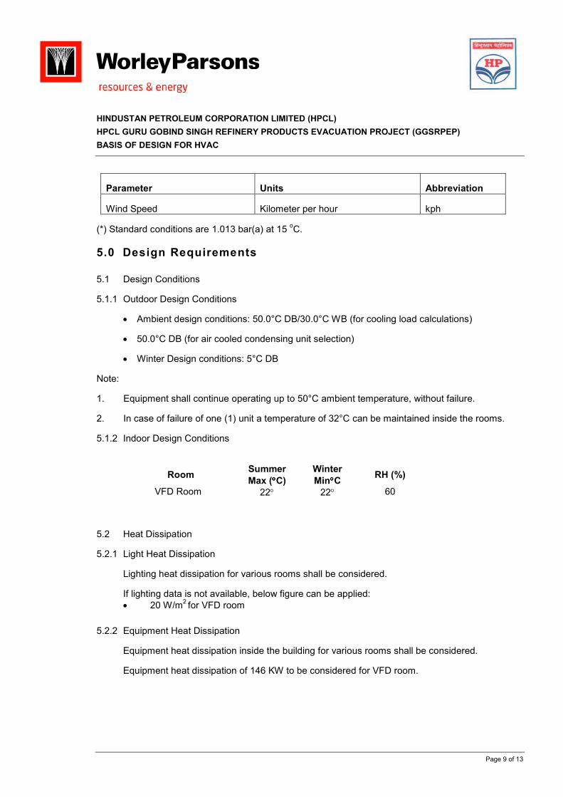
Wind Speed Kilometer per hour kph
(*) Standard conditions are 1.013 bar(a) at 15 oC.
5.0 Design Requirements
5.1 Design Conditions
5.1.1 Outdoor Design Conditions
• Ambient design conditions: 50.0°C DB/30.0°C WB (for cooling load calculations)
• 50.0°C DB (for air cooled condensing unit selection)
• Winter Design conditions: 5°C DB
Note:
1. Equipment shall continue operating up to 50°C ambient temperature, without failure.
2. In case of failure of one (1) unit a temperature of 32°C can be maintained inside the rooms.
5.1.2 Indoor Design Conditions
Room Summer
Max (°°°°C)
Winter
Min°°°°C RH (%)
VFD Room 22° 22° 60
5.2 Heat Dissipation
5.2.1 Light Heat Dissipation
Lighting heat dissipation for various rooms shall be considered.
If lighting data is not available, below figure can be applied:
• 20 W/m2 for VFD room
5.2.2 Equipment Heat Dissipation
Equipment heat dissipation inside the building for various rooms shall be considered.
Equipment heat dissipation of 146 KW to be considered for VFD room.
HINDUSTAN PETROLEUM CORPORATION LIMITED (HPCL)
HPCL GURU GOBIND SINGH REFINERY PRODUCTS EVACUATION PROJECT (GGSRPEP)
BASIS OF DESIGN FOR HVAC
Page 10 of 13
5.2.3 Heating/Cooling Load
Computerized calculations shall be preferred provided the software used is either of the
following (or an approved equal):
• Carrier, HAP or E20.
• Elite, Chvac - Commercial HVAC Loads
5.3 HVAC Design Criteria
• The VFD room shall be provided with two (2) equally sized air handling units each having
50% of the total capacity and two (2) equally sized air cooled condensing units each having
50% of the total capacity.
• The HVAC system shall be capable of maintaining the desired conditions at various rooms as
per clause no. 5.1.2 of this document.
• Sufficient air quantity shall be considered to remove heat gain from equipment, lights, solar,
to maintain each space at the required inside design conditions.
• All equipment, ducting and piping shall be arranged to provide required clearance for
installations, operation, inspection, maintenance and dismantling with the minimum
interference or removal of ducting, piping and equipment. Accessibility and maintenance
doors shall be installed in ductwork.
5.4 Noise Levels
Sound attenuators or other measures, if necessary, shall be applied for reducing the noise
generated by the equipment or air borne noise.
5.5 Infiltration
Fresh air infiltration may be considered in order to provide a minimum fresh air intake quantity.
0.5 air changes per hour fresh air can be considered as infiltration requirements.
5.6 Electrical Power Supply
HVAC power and control panel power section shall be directly fed from main electrical
distribution board to a single point and further distribution to HVAC equipment shall be under
the scope of HVAC Vendor.
Voltage rating of power feeder shall be 415 V ± 10 % AC, 3 Phase, 50 ± 5% Hz, 4 wire.
The power supply to the HVAC Control Panel shall be furnished from 240V AC/1-Phase/50Hz
power source, which are over-current protected. The HVAC Control Panel shall include a 24V
DC power supplies to drive local lamps, powering transmitters and for any other 24V DC
requirements. This power shall be derived by the HVAC Vendor internally. The HVAC Control
HINDUSTAN PETROLEUM CORPORATION LIMITED (HPCL)
HPCL GURU GOBIND SINGH REFINERY PRODUCTS EVACUATION PROJECT (GGSRPEP)
BASIS OF DESIGN FOR HVAC
Page 11 of 13
Panel shall also include power supplies to drive the motorized dampers and for any other
requirements.
Any other voltage required for equipment and controls shall be derived in the HVAC system
power and control panel.
5.7 Drainage System
The condensate water from air handling units shall be piped into the respective building
drainage system.
5.8 Potable Water Supply
When humidification is required, steam humidification shall be employed.
One potable water supply point shall be respectively provided.
5.9 HVAC System
Direct expansion (DX) type system with air handling units and air cooled condensing units shall
be considered for the VFD room of Substation building.
HVAC equipment capacity selection shall include 10% of the calculated cooling load as safety
factor or contingency.
Equipment shall be connected to ductwork via flexible connections to eliminate transmission of
vibration.
HVAC systems shall be designed to provide temperature and humidity controlled (where
specified) environments for equipment in accordance with the design criteria mentioned in
clause no. 5.1.2 of this document. System shall incorporate the use of filtration, cooling,
heating, and humidification/dehumidification as required to meet the design conditions.
Condensation within the building shall be prevented by proper sealing of service penetrations.
Vapour barrier shall be applied to chilled water piping and supply and return air ducts.
5.10 HVAC Control System
Dedicated HVAC Control Panel shall be provided with Central Air conditioning system as a
standard package. The local HVAC Control Panel shall be designed to monitor and control the
operation of all equipment associated with the HVAC systems, including, but not limited to air
handling units, air cooled condensing units, dampers, lights, transmitters. HVAC Control Panel
shall also monitor all temperature and humidity set-points. Detailed control logic diagrams shall
be developed for systems, with all control points, instrumentation and signals shown and
identified.
HVAC Control Panels shall provide one common alarm, as volt-free contact for remote
indication of any failure alarm monitoring by SCADA.
HINDUSTAN PETROLEUM CORPORATION LIMITED (HPCL)
HPCL GURU GOBIND SINGH REFINERY PRODUCTS EVACUATION PROJECT (GGSRPEP)
BASIS OF DESIGN FOR HVAC
Page 12 of 13
The controls for HVAC systems shall be interlocked by hardwire to the fire and gas alarm panel
for HVAC shutdown in case of fire detection.
HVAC Control system vendor shall produce shop drawings for HVAC control system.
HVAC system status shall be as below:
Abnormal Situation
HVAC system Normal
situation
Fire and
smoke
detection in
the building
Normal
power failure
Mechanical
failure
Air handling units Run Stop Stop Run standby
Air cooled
condensing units
Run Stop Stop Run standby
Fire dampers Open Close Close No standby
HVAC control system Run Run Run No standby
5.11 Air Distribution System
5.11.1 Ductwork
Generally, ductwork shall be designed and manufactured in accordance with the standards set
by SMACNA and in accordance with Specification for HVAC. Ducts shall be formed from sheet
steel with hot dip galvanized coating. Average thickness of zinc coating shall be equivalent to
not less than 0.6 kg/m2 of zinc for all surfaces.
Duct elements shall be constructed for optimal duct air flow, for example by using baffle plates,
turning vanes, reversing blades, etc. so that air turbulence, air borne noise and pressure losses
are minimized. Flexible ductwork shall not be used unless necessary, however length is to be
minimized (maximum length 1.0m).
Ductwork shall be designed to minimize noise transmission and to avoid noise generation from
components or fittings.
Ductwork air velocities shall not exceed the following limits:
Mains 8 m/s
Branches 6 m/s
Run-outs 4 m/s
All rectangular 45 to 90 degree elbows in both medium and low pressure ductwork shall contain
turning vanes. Radial elbows shall contain splitters.
HINDUSTAN PETROLEUM CORPORATION LIMITED (HPCL)
HPCL GURU GOBIND SINGH REFINERY PRODUCTS EVACUATION PROJECT (GGSRPEP)
BASIS OF DESIGN FOR HVAC
Page 13 of 13
Supply and return air ductwork in conditioned spaces shall be insulated. Insulated ductwork up
to 2.0m above finish floor level or exposed to outdoor air or in any location subject to physical
damage shall be provided with aluminium cladding.
Balancing devices shall be provided at each supply branch connection serving more than one
terminal device and each terminal device. Balancing devices shall also be provided at return air
ductwork as required to obtain required return airflow.
5.11.2 Dampers
Generally Volume Control Dampers (VCD) shall be provided at all duct branches in order to
balance the system and achieve design/required air flow rates.
Fire Dampers (FD) shall be fitted in ductwork/air transfer openings as per NFPA 90A, at all
firewalls. Fire dampers shall be constructed of galvanized sheet steel. The motorized fire
dampers shall be operated form the HVAC control panel. Motorized fire dampers shall be fail
safe type (fail to close).
5.11.3 Air Terminals
Terminal devices (outlets) shall be selected based on the following criteria:
• In occupied rooms, the air distribution shall be such that air velocity at 0.9 m from floor
shall never exceed 0.15 m/s.
• Pressure loss for each outlet on each ductwork branch or run shall be approximately
equal to ensure uniform air distribution.
• Supply air grille/diffusers shall be selected for required throw and pressure drop not to
exceed 20 Pa.
Return air inlets shall be selected and located based on the following criteria:
• Face velocity across the inlet shall be less than 2.5 m/s.
• Static pressure drop across inlets shall be less than 10 Pa.
• Inlets shall be located at adequate distances from supply devices to prevent short
circuiting of supply air.
• Air inlet/return devices should have volume control dampers.
5.11.4 Filters
Access sections with doors shall be provided at each filter section as required for maintenance,
filter cleaning and replacement. Filters shall be rated for efficiency of particulate matter removal
in accordance with the latest editions of ASHRAE Standard 52 dust spot test.
HINDUSTAN PETROLEUM CORPORATION LIMITED (HPCL)
Page 1 of 47
Guru Gobind Singh Refinery Products Evacuation Project (GGSRPEP)
Raman Mandi- Bahadurgarh and Raman Mandi- Bhatinda Multiproduct Pipeline
SPECIFICATION FOR HVAC
0435-JH0902-10-HV-SPC-0001
03.-Sept-2009
Sanghi Oxygen Compound 1, Mahal Industrial Estate Mahakali Caves Road Andheri (East), Mumbai - 400 093 India Phone: +91-22-67818000 Fax : +91-22-67818080 www.worleyparsons.com
© Copyright 2009 WorleyParsons
HINDUSTAN PETROLEUM CORPORATION LIMITED (HPCL)
HPCL GURU GOBIND SINGH REFINERY PRODUCTS EVACUATION PROJECT (GGSRPEP)
SPECIFICATION FOR HVAC
Page 2 of 47
SYNOPSIS
Disclaimer
This report has been prepared on behalf of and for the exclusive use of Hindustan Petroleum
Corporation Limited (HPCL), and is subject to and issued in accordance with the agreement
between Hindustan Petroleum Corporation Limited (HPCL) and WorleyParsons. WorleyParsons
accepts no liability or responsibility whatsoever for it in respect of any use of or HPCL upon this
report by any third party.
Copying this report without the permission of Hindustan Petroleum Corporation Limited (HPCL) or
WorleyParsons is not permitted.
PROJECT 435/JH0902- HPCL GURU GOBIND SINGH REFINERY PRODUCTS EVACUATION PROJECT (GGSRPEP)
REV DESCRIPTION ORIG REVIEW WORLEY- PARSONS APPROVAL
DATE CLIENT APPROVAL
DATE
A Issued for DIC / SQC
Arya Sarkar
Sameer Ishwad
Jeremy Wallace
N/A
B Issued For Review
Arya Sarkar
Sameer Ishwad
Jeremy Wallace
21-July-09
N/A
C Issued For Tender
Arya Sarkar
Sameer Ishwad
KMN Pillai
03-Sept-09
HINDUSTAN PETROLEUM CORPORATION LIMITED (HPCL)
HPCL GURU GOBIND SINGH REFINERY PRODUCTS EVACUATION PROJECT (GGSRPEP)
SPECIFICATION FOR HVAC
Page 3 of 47
CONTENTS
1.0 INTRODUCTION ................................................................................................................4
2.0 ORDER OF PRECEDENCE...............................................................................................5
3.0 DEFINITIONS .....................................................................................................................6
4.0 ABBREVIATIONS AND CODES AND STANDARDS ........................................................7
5.0 SITE DATA .......................................................................................................................11
6.0 SCOPE OF WORK ...........................................................................................................12
7.0 DESIGN REQUIREMENTS..............................................................................................13
8.0 HVAC SYSTEM DESCRIPTION ......................................................................................15
9.0 EQUIPMENT/MATERIALS ...............................................................................................16
10.0 INSTALLATION, TESTING, COMMISSIONING AND ACCEPTANCE TEST..................35
11.0 QUALITY ASSURANCE/QUALITY CONTROL................................................................36
12.0 PAINTING.........................................................................................................................37
13.0 DOCUMENTATION ..........................................................................................................38
14.0 WORK INCLUDED ...........................................................................................................41
15.0 GUARANTEE AND WARRANTY .....................................................................................42
16.0 SPARE PARTS.................................................................................................................43
17.0 SPECIAL TOOLS..............................................................................................................44
18.0 PERFORMANCE GUARANTEE ......................................................................................45
APPENDIX I DATA SHEET.......................................................................................................46
HINDUSTAN PETROLEUM CORPORATION LIMITED (HPCL)
HPCL GURU GOBIND SINGH REFINERY PRODUCTS EVACUATION PROJECT (GGSRPEP)
SPECIFICATION FOR HVAC
Page 4 of 47
1.0 INTRODUCTION
The document specifies minimum requirements for the Design, Engineering, Fabrication, Assembly,
Co-ordination, Procurement, Inspection, Testing, Installation and Commissioning of complete and
operable, heating, ventilating and air conditioning (HVAC) systems required for HPCL-GGSRPEP,
Project.
This specification along with the relevant Codes & standards describes the minimum requirements for
design, supply, installation and commissioning for HVAC system. It is not the intent to completely
specify all details of design and construction; however, any additional equipment, material, services
which are not specifically mentioned here, but are required to make the system complete in every
aspect in accordance with the technical specification and for safe operation and guaranteed
performance shall be covered under the scope of this specification. Nevertheless, the equipment and
installation shall conform to high standards of engineering, design and workmanship in all respects
and shall be capable of performing in continuous commercial operation in a manner acceptable to the
PURCHASER.
The Contractor/ Vendor shall make all possible efforts to comply strictly to the requirements of this
Specifications and other relevant Codes & Standards. In case, any deviations are considered
essential by the Contactor/ Vendor after making all possible efforts, these shall be separately listed in
the Contractor’s /Vendor’s offer under ‘LIST OF DEVIATIONS/ EXCEPTIONS TO THE TENDER
Docs. for the purchaser’s considerations. In the event, of any deviation not listed under the ‘List of
deviations / exceptions to the tender’, even though it is appearing in other part of the offer, shall not
be considered applicable. Deviations accepted by the purchaser are the only exceptions acceptable.
Hence all the requirements shall be binding on the Contractor /Vendor without any cost and schedule
implications to the purchaser.
The Contractor / Vendor shall be responsible for the co-ordination of all Sub-Suppliers and for the
overall guarantee of furnished equipment. It is the specific responsibility of the Supplier to invoke all
applicable referenced specifications to each Sub-Supplier Purchase Order.
The offered equipment shall be sourced from a regular and established manufacturer having requisite
design, manufacturing and testing facilities. The offered model shall be from the regular
manufacturing range of the supplier and the design shall have had a minimum of two years
successful field operation with the same model having the same design and materials of construction.
Relevant information of the offered equipment like catalogues; references, user’s certificates etc. shall
be furnished along with the offer.
HINDUSTAN PETROLEUM CORPORATION LIMITED (HPCL)
HPCL GURU GOBIND SINGH REFINERY PRODUCTS EVACUATION PROJECT (GGSRPEP)
SPECIFICATION FOR HVAC
Page 5 of 47
2.0 ORDER OF PRECEDENCE
The precedence for application of Project Documents, Codes, Standards, Design Engineering
Practices and regulatory requirements shall be as follows:
• Data Sheets (attached as an Appendix to this specification)
• This Specification
• Reference Drawings
• Project Specifications
• General Specifications
• Referenced Codes and Standards
HINDUSTAN PETROLEUM CORPORATION LIMITED (HPCL)
HPCL GURU GOBIND SINGH REFINERY PRODUCTS EVACUATION PROJECT (GGSRPEP)
SPECIFICATION FOR HVAC
Page 6 of 47
3.0 DEFINITIONS
For the purposes of this specification, the following definitions shall apply:
“CLIENT”, “OWNER” “TAKREER”, COMPANY
: HINDUSTAN PETROLEUM CORPORATION LIMITED (HPCL)
“CONTRACTOR” : WORLEYPARSONS the EPMC CONTRACTOR for the Project
“ENG. SUBCONTRACTOR” : The party which carries out the detail design of the project as a SUBCONTRACTOR to the CONTRACTOR
“SUPPLIER”, “VENDOR”, “MANUFACTURER”
: VENDOR, MANUFACTURER or Seller of the goods as defined in the Specification
“SUB-VENDOR” : Means any persons, firms, partnership, companies or a combination thereof (not being employees of EPC CONTRACTOR), to whom any part of the work has been subcontracted by MANUFACTURER, VENDOR or SUPPLIER.
“must” : signifies a legal or statutory requirement
“shall” : signifies a requirement made mandatory by this Specification
“may” : signifies a feature, which is discretionary in the context in which it is applied
“will” : signifies a feature which the suppliers may assume to be already present
“should” : Used where a provision is preferred, strong recommendation
HINDUSTAN PETROLEUM CORPORATION LIMITED (HPCL)
HPCL GURU GOBIND SINGH REFINERY PRODUCTS EVACUATION PROJECT (GGSRPEP)
SPECIFICATION FOR HVAC
Page 7 of 47
4.0 ABBREVIATIONS AND CODES AND STANDARDS
Abbreviations:
ADC Air Diffusion Council
AMCA Air Moving and Control Association
ARI Air conditioning and Refrigeration Institute
ASHRAE American Society of Heating, Refrigerating and Air conditioning Engineers
ASTM American Society for Testing and Materials
HVAC Heating, Ventilating and Air Conditioning
ISO International Organization for Standardization
ITP Inspection and Test Plan
NEBB National Environmental Balancing Bureau
NEMA National Electrical Manufacturers Association
NFPA National Fire Protection Association
QA/QC Quality Assurance/Quality Control
RMA Rubber Manufacturers Association
SMACNA Sheet Metal and Air Conditioning Contractors National Association
UL Underwriters Laboratories, Inc.
WP WorleyParsons
The Following codes & Standards shall be followed :
BS 759 Valves, Gauges & Other Safety Fittings.
BS 1387 Steel Tubes.
BS EN 1057 Copper & Copper Alloy Tubes for heating application.
BS EN 12449 Copper & Copper Alloy Tubes for general purposes.
BS EN 12451 Copper & Copper Alloy Tubes for heat exchangers
HINDUSTAN PETROLEUM CORPORATION LIMITED (HPCL)
HPCL GURU GOBIND SINGH REFINERY PRODUCTS EVACUATION PROJECT (GGSRPEP)
SPECIFICATION FOR HVAC
Page 8 of 47
BS 2879 Draining Taps
BS 3505 UPVC Pressure Pipes for Cold Potable Water
BS EN 10216-1 Seamless steel tubes for pressure purposes.
BS EN 10217-1 Welded steel tubes for pressure purposes.
BS 5150 Cast Iron Gate Valves
BS 5152 Cast Iron Globe Valves
BS EN 12334 Industrial valves, Cast Iron Check Valves.
BS 5154 Copper Alloy Globe, Check & Gate Valves.
BS 5588 Fire Precautions in the Design, Construction & Use of Buildings
BS EN 779 Particulate Air Filters for General Ventilation
BS EN 61260; 1996 Electroacoustics, Octave-band, and fractional octave-band filters
BS EN 60651:1994 Specification for Sound Level Meters
BS EN 60942:1998 Electroacoustics, Sound Calibrators
HVCA Heating & Ventilation Contractors Association Publications
ARI 210 Unitary Air Conditioning Equipment
ARI 270 Standard for sound rating of outdoor unitary equipment
ARI 360 Commercial and Industrial Unitary Air conditioning equipment
ARI 410 Forced circulation Air-cooling and Air-heating coils
ARI 430 Central Station Air-handling Unit
ARI 650 Standard for Air Outlets and Inlets
ASHRAE 14 Methods of testing for rating positive displacement condensing units
ASHRAE 15 Safety code for mechanical refrigeration
ASHRAE 20 Methods of testing for rating remote mechanical-draft air-cooled
refrigerant condensers
ASHRAE 52-76 Methods of testing Air cleaning Devices used in general ventilation
for removing particular matter
ASHRAE 90A Energy conservation in new building design (Sections 1 through 9)
HINDUSTAN PETROLEUM CORPORATION LIMITED (HPCL)
HPCL GURU GOBIND SINGH REFINERY PRODUCTS EVACUATION PROJECT (GGSRPEP)
SPECIFICATION FOR HVAC
Page 9 of 47
ASHRAE 70 Method of testing for rating the air flow performance of outlets and
inlets
ASHRAE 34 Number designation and safety classification of refrigerants
ASHRAE 111 Practices for measuring, testing and balancing a building heating,
ventilation, air conditioning and refrigeration systems
ASHRAE Hand books
CARRIER Handbook for air conditioning system design, Carrier air conditioning
company
ASTM A53 Standard Specification Pipe, Steel, black and hot-dipped, zinc-
coated, welded and seamless
ASTM A90 Standard Test method for weight of coating on zinc coated
(galvanised iron or steel articles)
ASTM A527 Standard Specification for steel sheet, zinc-coated (galvanised) by
the Hot-dip process, lock-forming quality
ASTM A 666 Standard Specification for Austenitic stainless steel, sheet, strip, plate
and flat bar
ASTM B62 Standard specification for composition bronze or ounce metal
castings
ASTM B88 Standard specification for seamless copper water tube
ASTM B280 Standard specification for seamless copper tube for air conditioning
and refrigeration field service
ASTM C552 Standard specification for cellular glass thermal insulation
ASTM D579 Standard specification for greige woven glass fabrics
ASTM E477 Testing Duct Linear Materials and prefabricated silencers for
acoustical and airflow performance
NFPA 70 National Electrical Code
NFPA 90A Standard for the Installation of Air Conditioning and Ventilating
Systems
NFPA 220 Standard on Types of Building Construction
NFPA 225 Method of Test of Surface Burning Characteristics of Building
Materials

HINDUSTAN PETROLEUM CORPORATION LIMITED (HPCL)
HPCL GURU GOBIND SINGH REFINERY PRODUCTS EVACUATION PROJECT (GGSRPEP)
SPECIFICATION FOR HVAC
Page 10 of 47
RMA IP-20 Specifications for Drives Using Classical Multiple V-Belts, and
Sheaves – Cross Sections, A,B,C and D
SMACNA-06 HVAC Duct Construction Standards – Metal and Flexible
ADC 1062:GRD Test Codes for Grilles, Registers, and Diffusers
ADC-01 Directory of ADC Certified Products
UL 181 Factory Made Air Ducts and Connectors
UL 207 Refrigerant – Containing Components and Accessories, Non
electrical
UL 303 Refrigeration and Air-conditioning Condensing and Compressor Units
UL 465 Central Cooling Air Conditioners
UL 555 Fire Dampers and Ceiling Dampers
UL 900 UL Standard for safety air filter units – Sixth Edition
AMCA 210 Design and Testing of Fans
AMCA 500 Test Methods for Louvers, Dampers and Shutters
NEMA 250 Enclosures for Electric Equipment (1000 Volts Maximum)
NEBB-01 Procedural Standards for Testing Adjusting of Environmental
Systems
IEC 61260 Electroacoustics, Octave-band and fractional-octave-band filters.
(Formerly IEC 225)
IEC 60651 Recommendations for sound-level meters. (Formerly IEC 651)
IEC 60942 Electroacoustics, Sound Calibrators. (Formerly IEC 942)
ISO 266 Acoustics – Preferred frequencies for measurements
ISO 1996 Acoustics, Description and measurement of environmental noise
ISO 9001 Quality Systems – Model for Quality Assurance in Design,
Development, Production, Installation and Servicing
ISO 9003 Quality Systems – Model for Quality Assurance in final inspection &
test
ISO 9004 Quality Management and Quality System Elements - Guidelines
HINDUSTAN PETROLEUM CORPORATION LIMITED (HPCL)
HPCL GURU GOBIND SINGH REFINERY PRODUCTS EVACUATION PROJECT (GGSRPEP)
SPECIFICATION FOR HVAC
Page 11 of 47
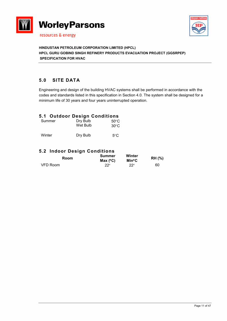
5.0 SITE DATA
Engineering and design of the building HVAC systems shall be performed in accordance with the
codes and standards listed in this specification in Section 4.0. The system shall be designed for a
minimum life of 30 years and four years uninterrupted operation.
5.1 Outdoor Design Conditions Summer Dry Bulb
Wet Bulb 50°C
30°C
Winter Dry Bulb 5°C
5.2 Indoor Design Conditions
Room Summer
Max (°°°°C)
Winter
Min°°°°C RH (%)
VFD Room 22° 22° 60
HINDUSTAN PETROLEUM CORPORATION LIMITED (HPCL)
HPCL GURU GOBIND SINGH REFINERY PRODUCTS EVACUATION PROJECT (GGSRPEP)
SPECIFICATION FOR HVAC
Page 12 of 47
6.0 SCOPE OF WORK
This specification defines the requirements for the design, engineering, assembly fabrication,
procurement, testing, balancing and installation and commissioning for satisfactory performance of
Heating, Ventilating and Air Conditioning (HVAC) @ Substation Building at Raman Mandi Pumping
Station for HPCL-GGSRPEP, Project.
The scope of the work described in this specification shall include complete HVAC systems as
specified herein. The VENDOR shall provide all supervision, pressure test, performance test,
material, equipment, machinery and all other items necessary to complete the HVAC systems. Any
material not specifically mentioned in this specification but required for proper performance and
operation shall be furnished and installed by the VENDOR. However, the SUBCONTRACTOR shall
provide and install all the items as required for complete system.
The equipment furnished according to this specification shall conform to the requirements contained
herein, unless modified in writing by the attachment or an addendum to this specification.
Compliance by the VENDOR with the requirements of this specification does not relieve the VENDOR
of his responsibility to supply equipment that is of proper design & construction, fully suited for all
specified conditions.
The VENDOR shall provide the requirements described below and attachments duly verified
including, but not limited to the following:
Air handling units
Air cooled condensing units
Refrigerant piping and accessories
Ductwork and accessories
Microprocessor based HVAC Control Panel
Field instruments, controls and accessories
Conduit and wiring required for the control system inputs, outputs, power wiring for the controllers,
actuators and terminal units
HINDUSTAN PETROLEUM CORPORATION LIMITED (HPCL)
HPCL GURU GOBIND SINGH REFINERY PRODUCTS EVACUATION PROJECT (GGSRPEP)
SPECIFICATION FOR HVAC
Page 13 of 47
7.0 DESIGN REQUIREMENTS
7.1 Internal Heat Gains
The internal (equipment) heat dissipation loads shall be verified and confirmed by the HVAC
contractor when sizing the AC equipment. For the equipment sizing purposes, the contractor shall
consider heat dissipation from the electrical equipment as well as lighting in the space. To estimate
the total cooling required, the total internal heat gains will then be added to heat transmission gains
through exterior walls/roof and heat gains from ventilation air (outdoor air).
7.2 General HVAC Requirements
Minimum outdoor air quantities for ventilation shall meet the requirements of ASHRAE standards.
Heating requirements shall be based on zero internal heat gain.
The air distribution system shall be designed to prevent generation of excessive noise and vibration.
Provide A/C unit's condensate drain piping to an approved receptor by the local codes or the project.
7.3 Air Contamination/Air Quality
Indoor or outdoor air may contain contaminants which may cause corrosion and affect the reliability of
the equipment. To maintain the air contaminants below acceptable levels, the following issues shall
be considered in the design:
a. Humidity control shall be used to protect against corrosion. Duct heaters and humidifiers shall
be provided (if required) in supply ducts to each zone to maintain design temperature and
relative humidity, if required.
b. To avoid the entrance of dust into the building, adequate filtration shall be provided in the air handling units.
7.4 Miscellaneous System Design Requirements
AC systems shall be shut down automatically via the fire alarm panel upon detection of smoke/fire by the building's fire protection system.
a. The CONTRACTOR shall be responsible for ensuring that all necessary fire dampers are provided within air-conditioning ducts penetrating fire wall/fire zone.
b. All equipment, ducts, pipes, controls, etc. shall be fully treated against corrosion and sealed against moisture, sand and dust ingress.
c. All equipment including ducts and pipes shall be vibration isolated by means of flexible piping, duct connectors, and vibration isolators as per ASHRAE requirements.
HINDUSTAN PETROLEUM CORPORATION LIMITED (HPCL)
HPCL GURU GOBIND SINGH REFINERY PRODUCTS EVACUATION PROJECT (GGSRPEP)
SPECIFICATION FOR HVAC
Page 14 of 47
d. Noise caused by HVAC equipment shall be 10 dB (A) below the noise level acceptable limits stated for the applicable buildings. Noise caused by HVAC equipment can be reduced by any one of the following:
• Air Duct Silencers
• Sound Attenuators
• Duct Lining
• Selecting Quieter equipment
HINDUSTAN PETROLEUM CORPORATION LIMITED (HPCL)
HPCL GURU GOBIND SINGH REFINERY PRODUCTS EVACUATION PROJECT (GGSRPEP)
SPECIFICATION FOR HVAC
Page 15 of 47
8.0 HVAC SYSTEM DESCRIPTION
8.1 Substation Building
A direct expansion (DX) type system comprising of air handling units and air cooled condensing units and other accessories shall be installed in the Substation building. The system shall consist of two (2) air handling units each having a capacity of 50% of the total supply air quantity and two (2) air cooled condensing units each having a capacity of 50% of the total cooling load. The air handling units are to be located in the HVAC room of the building. Air cooled condensing units are to be located outside to the building. It is the responsibility of the Contractor/Vendor to verify and confirm the location of condensing units as per the suitability and requirements of the Owner.
8.2 Interface with fire protection/suppression system
Fire and gas alarm panel shall be interfaced to HVAC control panel. Upon detection of smoke or fire by the fire protection system, the AC units in the Substation building shall be shut down via the fire and gas alarm panel.
HINDUSTAN PETROLEUM CORPORATION LIMITED (HPCL)
HPCL GURU GOBIND SINGH REFINERY PRODUCTS EVACUATION PROJECT (GGSRPEP)
SPECIFICATION FOR HVAC
Page 16 of 47
9.0 EQUIPMENT/MATERIALS
All HVAC equipment and materials shall be certified to have been tested and rated for performance and to conform to all applicable codes and standards listed herein.
All HVAC equipment and materials shall be new and be the latest products selected from the approved vendors’ list:
9.1 Air handling units a) The air handling unit shall be completely factory assembled, wired, charged, tested and be
ready for immediate installation. Each unit shall comprise of centrifugal supply air fan with motor, cooling coil and washable air filters, and condensate drain pan. The unit shall be enclosed in a weather proof composite casing constructed from galvanized sheet metal with a stove enameled finish. The casing shall be fully insulated and be provided with access panels/doors for maintenance.
b) The whole unit shall be mounted on a four points of equipment 150mm wide x 20mm thick rubber sheet isolation pad.
c) Filters: Pre filter shall be 2” thick pleated disposable type filter with an average efficiency of 65% and an average arrestance of 90-92% in accordance with ASHRAE standard 52-76. After filter shall be disposable type with 95% efficiency and arrestance to ASHRAE standard 52-76.
d) The cooling coil shall be constructed from seamless deoxidized copper tubes mechanically bonded with copper fins. All cooling coils shall be selected for a face velocity of not more than 2.5m per second and moisture carryover shall be avoided.
e) A stainless steel sheet drain pan shall be fitted under each coil or coil section and a condensate drain outlet provided with running trap with seal at 150% min. of fan static pressure at cooling coil to discharge to nearest drain point.
f) The fan shall be backward curved multi-vane impeller centrifugal type having non-overloading characteristics.
g) All wheels shall be statically and dynamically balanced at their rated speed in the factory as an assembled unit and shall be run on large diameter precision ground solid steel shafting in heavy duty self aligning grease lubricated deep groove ball bearing plumber block.
h) Where two fans are fitted, these shall be connected by means of and driven through suitable flexible couplings. The fan(s) shall be mounted on a fabricated steel framework suitably extended to receive on one side a totally enclosed fan cooled motor, complete with slide rails for tensioning of V belt drive. Each drive shall have a minimum of two belts incorporating pulleys with taper lock bushes.
i) The whole fan supporting framework shall be completely isolated from the remainder of the unit by means of rubber in shear anti vibration mountings having a minimum deflection of 4mm. Flexible neoprene connectors shall be fitted to fan discharge with an external spigot termination.
HINDUSTAN PETROLEUM CORPORATION LIMITED (HPCL)
HPCL GURU GOBIND SINGH REFINERY PRODUCTS EVACUATION PROJECT (GGSRPEP)
SPECIFICATION FOR HVAC
Page 17 of 47
j) The fan motor shall be suitable for 415V 3-phase 50Hz electrical supply and for continuous running in ambient temperatures of 50°C minimum.
k) The fan motor, pulleys, greasing points, etc., shall be arranged for ease of maintenance.
l) The controls shall be factory wired and tested and be completely enclosed within the unit. A return air thermostat shall be provided automatically cycling the compressor to maintain room conditions and shall also provide cold start operation.
m) The following spares shall be provided: - 2 no. complete set of control fuses - 1 no. complete set of run/trip lights and bulbs - 1 no. complete set of V belts for each air handling units. - 1 no. set of washable filter elements for each unit. - 1 no. set of bearings for each fan set - Special tools for routine maintenance
n) Remote Control/Panel: Contains controls and indicator lights as follows:
- On-off fan switch - Supply fan operating indicator light - Mechanical cooling malfunction indicator light - Clogged filters indicator light - Phase failure protection - Time delay relay - Anti-freeze protection
o) Electrical convenience outlet: 415V 3-phase 50Hz fused outlet, separately fused, located in
unit cabinet.
p) Unit shall be certified as complying with provisions of ARI 360 and 270 and UL 465, as
applicable. Contained within the unit weatherproof casing shall be all factory Refrigeration
Institute (ARI) Standard 430 for fans and 410 for coils.
9.2 Air cooled condensing units
Each condensing unit shall comprise of multiple compressors and capacity matched air cooled condensers. Condensing units containing duplicate compressors/refrigerant circuits shall be preferred. a) Each compressor unit shall be of the serviceable hermetic design, with suitable
vibration isolators and crank case heater and automatically reversible oil pump. Refrigerant compressors shall be of the reciprocating or rotary (semi-hermetic or hermetic) type with suction valve unloaders for refrigeration capacity control. The, compressor unloader shall be hydraulically controlled. A hot gas muffler shall be provided with each unit. Compressors shall be provided with complete internal motor protections against motor overloads and motor winding overheat, with manual reset that discharge during manual operation, high pressure cut-out: Manual Reset, low pressure cut-out: Manual Reset, oil failure switch, crankcase heater that de-energize during compressor operation, discharge and suction stop valves, mufflers, automatically reversible oil pump for pressurized lubrication and time delay relay to prevent short-cycling. All piping connection shall have flexible pipe connections
HINDUSTAN PETROLEUM CORPORATION LIMITED (HPCL)
HPCL GURU GOBIND SINGH REFINERY PRODUCTS EVACUATION PROJECT (GGSRPEP)
SPECIFICATION FOR HVAC
Page 18 of 47
approved for refrigerant use. Refrigerant shall be R-134A or approved equivalent. For capacity control, the compressor shall unload in steps of 50%. The electric unloader shall be factory installed and Hot-gas by pass valve and piping on one compressor.
b) Condenser coil construction shall be seamless copper tube, with "Herasite" coated aluminum extended surface plate fins integral with or mechanically attached to the tube. All components of the main power panel and all control devices shall be UL listed. Construction and ratings shall be in accordance with ARI standard 210, 270 and 410 and shall comply with ASHRAE 15 Safety Codes, and the National Electrical Code.
c) The casing shall be fully weatherproofed for outside installation and be arranged to allow for an ease of maintenance. An integral control panel shall be provided with a lockable hinge access door. The control panel shall be factory pre-wired and tested and shall incorporate all necessary pressure detectors and overload devices to facilitate fully automatic operation.
d) Minimum degree of ingress protection for the motors shall be to IP 56. All motors shall be suitable for 415V 3-phase 50Hz electrical supply and be suitably insulated to IEC 60085 to continuously run in ambient temperatures of 50°C.
e) Air-conditioning equipment shall have suitable accessories to prevent surface condensation and to prevent carryover of condensed moisture into the ducts through supply air stream.
9.3 Vibration Isolators
Vibration isolators shall be provided for all motor driven equipment.
9.4 Refrigerant pipework
Refrigerant piping shall be direct expansion (DX) type hard copper tubing conforming to ASTM B88-
62 Type L with seamless wrought copper solder type fittings, isolation valves, filter-drier of the
replaceable core type with micronic filtration, and sight glass as required. Piping 9.5 mm and smaller
shall be type K
9.5 Valves
Valves 29 mm and smaller shall be forged brass body, diaphragm type, packless globe valve with
solder ends. Valves 35 mm and larger shall be bronze alloy, non-rotating disk, nylon seats, bolted
bonnet globe valve with solder ends.
9.6 Pipe insulation
Insulation shall be applied in accordance with MANUFACTURER'S instructions over clean, dry pipe
after all testing is completed and approved. Pipe insulation shall be heavy density rigid fiberglass with
factory applied vinyl coated embossed foil vapour barrier laminate jacket with pressure sealing lap
adhesive. The insulation shall be rated non-combustible by Underwriters Laboratories. Insulation for
suction lines shall have a minimum thermal resistance (R value) of 1.46 meter-degree Kelvin per watt.
Liquid and hot gas lines outside the building shall be insulated with minimum 25 mm thick glass fiber
HINDUSTAN PETROLEUM CORPORATION LIMITED (HPCL)
HPCL GURU GOBIND SINGH REFINERY PRODUCTS EVACUATION PROJECT (GGSRPEP)
SPECIFICATION FOR HVAC
Page 19 of 47
insulation with weatherproof covering. Insulation shall be Owens Corning Fiberglass ASJ/SSL or
equal.
9.7 Condensate drain piping
All condensate drains from air conditioning equipment shall be trapped and vented with condensate
drain pipes to be routed to an approved receptor. Approved indirect waste receptors shall be piped
and drain to the sanitary sewer system. An alternate method shall be to terminate condensate drain
piping at outdoor dry-well type sumps where condensate shall seep to below grade.
9.8 Ductwork
9.8.1 Ductwork Materials
All material used in fabrication of ducts, plenums, stiffeners and supports shall be new
galvanized steel. Sheet metal shall be galvanized steel sheet metal with a minimum zinc
coating of 0.6 kg per square meter. Duct fabrication and installation shall be in accordance with
SMACNA standards as mentioned in clause 4.0 of this document.
Ductwork materials shall be in accordance with the following schedule:
a) Zinc Coated Steel Sheets
14 gauge and over (thinner), ASTM A527, Coating Designation G90 Lock Forming Quality.
Under 14 gauge (thicker), ASTM A526, Coating Designation G90 Commercial Quality.
b) Structural Steel Shapes
ASTM A36 plain or zinc coated in accordance with ASTM A123.
c) Bars
ASTM A575 or A576, plain or zinc coated in accordance with ASTM A123 or ASTM A164,
Type GS.
9.8.2 The Gasket Mater ia ls shal l be as fo l lows:
a) For joints subject to disassembly and removal: Neoprene, 1/8 inch thick, ASTM D1056,
Grade RE43-41 to RE45-E1, cellular solid or 30 - 40 Shore A durometer neoprene, with
dovetail joints or equal.
b) For joints not subject to disassembly and removal: Weatherproof Type 1202t, 1/8 inch
thick tape with dovetail joints, Foster 30-02 sealant, Epolux Cadaseal 770, as applicable to
the joints construction or equal.
HINDUSTAN PETROLEUM CORPORATION LIMITED (HPCL)
HPCL GURU GOBIND SINGH REFINERY PRODUCTS EVACUATION PROJECT (GGSRPEP)
SPECIFICATION FOR HVAC
Page 20 of 47
Products which contain asbestos are prohibited. This prohibition includes items such as packing or gaskets even though the item is encapsulated or the asbestos fibers are impregnated with binder material.
9.8.3 Hangers , Suppor ts, and Support ing Steel
Hangers for ductwork shall be in accordance with SMACNA, Low Pressure Duct Construction Standards. Equipment or ductwork shall be supported only from structural steel, reinforced concrete, or solid masonry.
Hangers and supports for equipment and ducts when attached to structural steel shall be welded or mechanically attached using manufacturers’ standard clamps, brackets or clips. For cases if these need to be attached to reinforced concrete or solid masonry structures, attachment shall be done by using manufacturers’ standard inserts or fasteners. All welds to structural members and supports from hollow masonry shall be subject to the approval of TAKREER, and manufacturer’s load ratings for any device shall not be exceeded.
Threaded weld studs will be permitted. However, threaded weld studs shall be used in tension only and in specific areas as approved by TAKREER. Threaded weld studs shall meet all manufacturer’s requirements and / or limitations including restrictions on stud size for overhead weld positions.
Stiffener angles may be used as part of the hanger system in ducts, if the stiffener angle is sized to meet the sum of the stiffener and trapeze load requirements. Do not exceed hanger spacing requirements.
Supports for rectangular ducts, supported from above, shall be the trapeze type with shelf angle or structural tubing and rod or angle hangers, and if supported from vertical structural, by an angle bracket type.
When reinforcing is applied to the longer sides only, the reinforcing shall be tied together by welding an angle or rod between the reinforcing members on each of the unreinforced sides of the duct. When reinforcing is applied to the four sides, all corner joint shall be welded together.
Strap hangers shall not be used for the support of vertical ducts. Equipment shall be suspended by rods and angles, in accordance with manufacturer’s instructions.
9.8.4 Elbows
Rectangular radius elbows shall be standard radius (R - 1.5 w) wherever space permits. Short radius rectangular elbows shall be provided with vanes. All square throat rectangular elbows shall be provided with single thickness turning vanes. Turning vanes in ducts with acoustical lining shall be anchored, riveted or welded to the duct.
Turning vanes shall be 2 inches radius, shall have a 0.75 inch trailing edge, shall be spaced 1 - 1/2 inches O.C., and shall be installed in accordance with SMACNA Standards. The use of spot welding or sheet metal screws to attach either turning vanes or splitters to the elbow cheek is not permitted.
HINDUSTAN PETROLEUM CORPORATION LIMITED (HPCL)
HPCL GURU GOBIND SINGH REFINERY PRODUCTS EVACUATION PROJECT (GGSRPEP)
SPECIFICATION FOR HVAC
Page 21 of 47
Round elbows shall be machine formed and of the same metal gauge requirements as for the straight lengths. Centerline radius of elbows shall be 1.5 times the diameter except reducing elbows shall have a centerline radius of 1.5 times the diameter of the larger end. Multi-piece round elbows shall be made of a minimum of 5 pieces.
9.8.5 Branch Take-of fs and Tees
Branch takeoffs shall be made at main duct transverse joints using straight duct sections and elbows. Tapped tee connections where required shall be provided with extractors.
Tees in main ducts shall be made by elbows joined at the main duct transverse joint or, if with square throat, may be of one piece with fixed splitter. Short radius tees shall be provided with single thickness turning vanes.
9.8.6 Access and Inspect ion Doors
Access and inspection doors shall be provided in sheet metal work. Inspection doors shall be located at:
a) Motor operated dampers
b) Fire dampers
c) Splitter dampers
d) Turning vanes (upstream side)
e) Other similar items requiring inspection or maintenance
Access doors shall be to provide personnel entry into the following unless provided by the equipment manufacturer:
a) Filter plenums
b) Return air plenums
c) Other such locations requiring personnel access into a space
Inspection doors shall provide minimum openings of 120 square inches, unless otherwise specified. Access doors shall have minimum size of 16 inches by 24 inches and not exceed 20 inches by 54 inches. All access doors shall open against the pressure in the duct or plenum.
HINDUSTAN PETROLEUM CORPORATION LIMITED (HPCL)
HPCL GURU GOBIND SINGH REFINERY PRODUCTS EVACUATION PROJECT (GGSRPEP)
SPECIFICATION FOR HVAC
Page 22 of 47
Access and inspection doors shall be constructed to the following details:
a) Not exceeding 16 inches by 24 inches: Single panel-insulated type, tight sealing,
two hinge, two latch type and gasket seal.
b) Larger than 16 inches by 24 inches: Double panel, insulated type, tight sealing two
hinge, two latch type and gasket seal. Inspection doors only shall be removable
non-hinged type.
9.8.7 Ins trument Test Holes
Instrument Test Holes shall be Ventlock 699, as manufactured by Ventfabrics, Inc., or equal as approved.
9.8.8 Air Distr ibut ion Devices
Air Distribution Devices shall be provided as part of the Air Distribution System and as specified herein. Diffusers, registers, and grilles shall be manufactured from extruded aluminum and shall be supplied complete with opposed blade volume control dampers. Both dampers and grilles shall have concealed screw type fixings. Spring clip fixings shall not be permitted. The required air quantity shall be distributed evenly to the space intended without causing noticeable drafts or dead spots anywhere in the occupied zone. All return air square diffusers shall be identical to the supply air diffuser within each conditioned zone.
Supply Ceiling Diffusers (SCD) shall be complete with opposed blade damper and equalizing grid. SCDs shall be two, three or four-way throw as required by their locations. Size and capacity of all inlet and outlet shall meet the requirement of the system.
9.8.9 Duct Accessor ies
A. Manual Volume Dampers
Manually Operated Multi-blade Dampers (Rectangular Ductwork):
1. Configuration: Manually operated dampers shall be of the opposed blade type.
Single blade dampers are not acceptable. Where required, duct-mounted dampers shall be fabricated with blades parallel to the longest side of the ductwork in which they are installed.
2. Frames: Frames shall be fabricated of 7.6 cm. wide by 18 ga. USS (minimum) roll-formed galvanized steel or 5 cm. x 1.27 cm. (min.) galvanized structural channel with integral reinforcing ribs and counting flanges for ease of installation.
3. Blades: Blades shall be fabricated of 16 ga. USS (minimum) galvanized steel and sized no greater than 15.2 cm. in width or 121.9 cm. in length.

HINDUSTAN PETROLEUM CORPORATION LIMITED (HPCL)
HPCL GURU GOBIND SINGH REFINERY PRODUCTS EVACUATION PROJECT (GGSRPEP)
SPECIFICATION FOR HVAC
Page 23 of 47
4. Blade Shafts and Bearings: Blade shafts shall be 1.27 cm. round, hex or square, cadmium plated steel and shall operate in nylon or oil impregnated bronze bearing mounted in the damper frame. Round blade shafts are to be thru-bolted or thru-pinned to the damper blades.
5. Linkage: Linkage shall be cadmium plated steel assembly of interconnecting crank arms attached to the shaft of each damper blade. This Linkage is to be mounted external to the air stream.
6. Seals: Dampers shall be provided with flexible metal or elastomeric jamb seals. Additionally, an extruded vinyl or elastomeric edge seal is required along the length of each blade.
7. Accessories: Each damper shall be furnished with an extra shaft extension, hat channel bracket, manual lever and locking quadrant.
B. Motorized Dampers
The Contractor shall furnish and install, control dampers as required for the proper
functioning of the system.
All control dampers shall be opposed blade.
Dampers frames shall be for formed channels of not less than 1.8 mm galvanized
steel with mounting holes for enclosed duct mounting.
Damper blades shall be of not less than 1.5 mm form galvanized steel. Blades on
multi-blade dampers shall not exceed 200 mm in width and 1200 mm in length. Blade
shaft bearings shall be provided at the ends of each blade. Blade side edges shall
seal off against spring stainless steel seals.
Dampers shall be supplied in standard sizes, in 50 mm even increments, with
transition as necessary to mating duct sections.
Dampers shall be suitable for operation within the temperature limit of – 40ºC to
93ºC. Horizontal dampers shall have a rated face velocity of 2 m/s at 1500h Pa static
pressure differential.
Dampers used for shut of function shall be if the low leakage type.
Damper blades shall have neoprene or PVC edging on all outside air dampers.
C. Back draft Dampers
Back draft dampers shall be low leakage with parallel blades and neoprene edge
seals.
Damper frames shall be constructed from galvanized sheet steel with aluminium
blades. Bearing shafts shall be stainless steel, on brass bearings.

HINDUSTAN PETROLEUM CORPORATION LIMITED (HPCL)
HPCL GURU GOBIND SINGH REFINERY PRODUCTS EVACUATION PROJECT (GGSRPEP)
SPECIFICATION FOR HVAC
Page 24 of 47
All blades shall be coupled at the blade centres and shall be in width of not more than
1000 mm, with maximum blade size of 200 mm.
Leakage shall not exceed 10 m³/h per m² at 1000 Pa (Damper closed) pressure
differential.
D. Fire Dampers
Fire dampers shall be provided in the ducting systems where ducting passes through
a wall or floor forming a fire zone or barrier.
All fire dampers shall be electrically operated interfaced with the HVAC control
system to close by spring return actuator on de-energisation of the power supply.
On restoration of power, the actuator motor shall open the damper and shall
simultaneously prime the spring release. Opening and closing times of the damper
shall not exceed 10 seconds. All dampers shall be complete with a micro-switch to
indicate the status of the damper (open or closed) at the main air conditioning control
panel.
Damper casings shall be completely air tight and constructed from galvanized sheet
steel of not less than 1.6 mm thickness with continuously welded corners. Inlet and
outlet connections shall be spigots formed as an integral part of the construction.
Any damper blade or shutter shall be constructed so as not to distort in use and shall
be made from either stainless steel or non combustible asbestos free fibre silicate
plates, 40 mm thick. Damper blades shall close against a steel stop around the whole
periphery of the damper with at least 20 mm overlap. The clearance between the
blade and sides of the duct shall be at least 0.01 mm of damper diameter length of
side. Multi-leaf damper blades shall overlap by at least 20 mm.
An insulated, double skin access door shall be provided adjacent to each fire damper
for service inspection and resetting.
Where the damper is fitted to a wall or floor, the damper casing shall be fitted with
building-in lugs.
E. Access Doors
1. General: Access doors are to be installed in ducts, casings, and housings as
specified below. Unless otherwise noted, access doors are to be made of
the same material as ducts, casings, or housings in which they are installed.
Insulate access door with an equal amount of insulation as required for the
ductwork or housings in which they are installed.
2. Access Doors for Rectangular Ducts
HINDUSTAN PETROLEUM CORPORATION LIMITED (HPCL)
HPCL GURU GOBIND SINGH REFINERY PRODUCTS EVACUATION PROJECT (GGSRPEP)
SPECIFICATION FOR HVAC
Page 25 of 47
a. Access doors are to be installed in ducts at each vaned elbow or tee,
volume damper, fire damper, smoke damper, duct-mounted coil, fan,
air flow measuring station, and any duct-mounted instrumentation.
b. Access doors shall be installed in the largest duct side unless this
location provides poor access or is obstructed by surrounding
conditions. Doors shall be furnished in accordance with SMACNA.
F. Hangers and Support Systems
1. Duct hangers and support systems shall be sized and installed in accordance
with SMACNA.
2. Sway bracing shall be fabricated to insure proper rigidity of the duct.
3. Duct support should be installed to handle a proper portion of the load.
G. Duct Connections to Equipment
1. Duct connections to air conditioning equipment shall be angle reinforced,
flanged connections secured by 0.64 cm. dia. bolts on 20.3 cm centers
(maximum). Joints are to be gasketed with red rubber on high density
neoprene and sealed air-tight.
2. This requirements applies to such equipment as air handling units, fans,
packaged units, cooling coils, automatic dampers, filtration equipment, airflow
measuring devices, sound attenuators, etc. unless specifically noted
otherwise.
9.9 Duct insulation
All insulation materials, including adhesives, sealants, and tapes, shall have flame spread, smoke
developed, and fuel contributed ratings of not more than 25, 50 and 50 respectively, in compliance
with NFPA 90A. The insulation materials shall be suitable for temperatures up to 121 °C.
Thermal Insulation
a.) Thermal insulation to ductwork shall be carried out by specialists and strictly in
accordance with this Specification. No thermal insulation shall be applied to any
low velocity ductwork prior to inspection by the Engineer and a site instruction
received in writing from the Engineer authorizing the application of thermal
insulation. No thermal insulation shall be applied to high velocity ductwork prior
to the ductwork being inspected by the Engineer, satisfactorily pressure tested
and a site instruction received in wiring authorizing the application of thermal
insulation.
HINDUSTAN PETROLEUM CORPORATION LIMITED (HPCL)
HPCL GURU GOBIND SINGH REFINERY PRODUCTS EVACUATION PROJECT (GGSRPEP)
SPECIFICATION FOR HVAC
Page 26 of 47
b.) In order that tests can be made of the thickness of the applied insulation, the Contractor shall allow for the cost of cutting away any one section of each thickness of insulation to ductwork or plant for inspection by the Engineer. If the insulation proves to be the thickness specified then the cut section shall be made good and the whole installation shall be completed. Should any cut portion show a deficiency in thickness, further portions shall be cut away at the direction of the Engineer for inspection. If a deficiency of thickness or any other defects are found, the Contractor shall remove the whole of the insulation installed, or as the Engineer directs, and shall then supply, deliver and apply new insulation complying with the Specification and install it to the satisfaction of the Engineer. This work shall be carried out at the Contractor’s own expense.
c.) Insulation shall be applied to all ductwork, volume control dampers, sound attenuators, and other items of equipment contained within the Specification detailed below.
d.) No insulation shall be concealed within false ceilings, vertical or horizontal builder’s work shafts prior to inspection and approval by the Engineer.
e.) All fibre glass slabs shall have a density of not less than 48 kilograms / cubic meter.
f.) All insulation shall be carefully applied using appropriate adhesive, ends and edges of sheets shall be lapped sufficiently and sealed where insulated ductwork enters or leaves the building.
g.) Rectangular supply air ductwork within air conditioned zones shall be insulated using 25 mm rigid fibreglass slabs, aluminium foil-backed secured to the ductwork using an approved adhesive and 75 mm wide aluminium tape at all joints. Insulation shall also have 25 mm wide galvanized bands secured at 600 mm centres. The whole shall be securely wrapped in 4 oz. canvas, all joints lapped, sealed with adhesive and then sewn in position. Two coats ‘Sealfas’ vapour seal shall be applied. Ductwork within air conditioned ceiling zones shall have one further final vapour seal brush coat. Ductwork exposed to view shall be finished two coats gloss paint to an approved colour. Return air ductwork within air conditioned zones need not be insulated.
9.10 Volume dampers
Volume damper shall be one gauge heavier than the duct and reinforced where required. Damper
over 200 mm in height shall be of multiple opposed blade type with factory manufactured linkage
assembly.
9.11 Electric duct heaters
9.11.1 General
Electric Heat shall be duct mounted, with tubular fins, flanged type construction. The unit
shall consist of framing, heater elements, terminal box and safety device all wire-up and
assembled ready for installation.
HINDUSTAN PETROLEUM CORPORATION LIMITED (HPCL)
HPCL GURU GOBIND SINGH REFINERY PRODUCTS EVACUATION PROJECT (GGSRPEP)
SPECIFICATION FOR HVAC
Page 27 of 47
Each electric heater shall be UL listed.
9.11.2 Framing
Electric heater frame and control box shall be fabricated from heavy gauge aluminized
steel. Frames shall have 40 mm. flanges with pre-drilled holes designed for mounting
between flanged sections of ductwork. Control box shall be hinged, solid cover type.
Fibreglass insulation, 15 mm, thick and 48 kg per cubic meter density, shall be provided
between the heating coil and control box for condensation protection. Stainless steel
hardware shall be provided for corrosion resistance.
9.11.3 Heater Element
Elements shall be finned tubular type having copper plated steel fins brazed to copper
plated steel sheath. Terminals shall be sealed with silicone rubber to protect against
moisture.
The heating element shall be rated for 415 Volts AC, 3-Phase, 50 Hertz. Control circuit
voltage shall be derived by the Vendor from the main 415 Volts AC, 3 phase, 50 hertz
supply. Resistance element shall be 80% nickel, 20% chromium, Type A, wire. Heating
element shall be SCR controlled.
9.11.4 Terminal Box and Safety Devices
Terminal box shall be provided with solid cover to minimize dust infiltration and shall be
hinged interlocking disconnect switches shall be provided. Heater terminal box shall be
totally enclosed without perforated louvers or grills. All factory wiring shall be rated at 105
°C and 600 V. Main supply terminals shall be provided for copper supply wires. Built-in
components shall include disconnecting break magnetic three pole contactors, door
interlock switch, 100 percent step less modulation SCR solid state controller, pressure-type
airflow switch, branch circuit fusing, “power on” pilot light, and single terminal block to
accept the number, type and size of conductors as shown on the electrical power supply
drawings.
Safety devices shall be a linear limit automatic reset thermal cut-out for primary over
temperature protection and a secondary linear limit cut outs with manually reset in the
power lines to de-energize elements if the primary cut-out fails. All safety devices shall be
serviceable through terminal box without removing heater frame from duct.
The heater controls shall be arranged so that the heating elements cannot be energized
when minimum air flow through the heater does not exist.
HINDUSTAN PETROLEUM CORPORATION LIMITED (HPCL)
HPCL GURU GOBIND SINGH REFINERY PRODUCTS EVACUATION PROJECT (GGSRPEP)
SPECIFICATION FOR HVAC
Page 28 of 47
9.12 Humidifier
9.12.1 General
Humidifier Units shall be self contained manufactured package, cabinet type, electric
evaporative, consisting of disposable steam cylinders, fill and drain assembly and
associated controls.
Unit shall be provided with steam dispersion system complete with vapour hose,
condensate drain tubes and accessories.
Unit shall be provided with mounting supports and suitable for 415 Volts, 3-Phase, 50 Hertz
power supply.
The humidifier cabinet shall be constructed of sheet steel with baked enamel finish. Cabinet
shall have a hinged and locked access door on the electrical compartment and a separate
removable and lockable access door on the cylinder compartment. The cabinet shall
contain the steam cylinder, fill and drain assembly and the electric / control compartment.
9.12.2 Steam Cylinders
The Steam Generating Cylinders shall be disposable plastic containers complete with grid
type electrodes, sensing probes, quick change fittings for steam, electrical and fill / drain
connections.
The sensing probes shall detect water level and actuate safety control circuit as necessary.
9.12.3 Fil l and Drain Assembly
The Fill and Drain Assembly shall consist of solenoid valves, one for fill and one for drain
and fill cup with air gap between the fill pipe and cup.
The Fill Solenoid Valve shall have a built-in strainer and flow regulating orifice.
The Fill and Drain assembly shall provide automatic refill, low water cut-off functions and
automatic drain / flush sequence.
9.12.4 Electrical and Control Devices
Electrical and control devices shall be provided and mounted on a sub-panel within the
enclosure. Control devices shall include solid state control system, magnetic contactor for
HINDUSTAN PETROLEUM CORPORATION LIMITED (HPCL)
HPCL GURU GOBIND SINGH REFINERY PRODUCTS EVACUATION PROJECT (GGSRPEP)
SPECIFICATION FOR HVAC
Page 29 of 47
each heater, fuse for heating elements, control circuit transformer, numbered terminal strips
and other devices.
The solid state control system shall provide the following functions as a minimum:
• Monitor water conductivity in the cylinder.
• Automatic filling / draining system in order to maintain the desired water conductivity.
• Control the steam generation by the room humidistat. The steam output capacity shall be adjustable from 20 to 100 percent.
• Prevent overfilling of the cylinder to keep water from entering the steam supply outlet and energize the safety control circuit.
9.12.5 Steam Dispersion System
The Steam Dispersion Device shall consist of steam discharge manifold / separator and
dispersion tubes. The steam discharge manifold shall span the width of the duct,
constructed of stainless steel tube and fitted with connections for dispersion tubes.
The dispersion tube shall extend the height of the duct and fitted with two rows of tubelets
centred on the diametric line and spaced at 1-1/2” apart or as recommended by
manufacturer. The tubelets shall be made of non-metallic material designed for steam
temperatures and shall extend through the wall of and into the centre of dispersion tubes
and incorporate a properly sized calibrated orifice.
The Steam Discharge Manifold / Separator shall be provided with a return leg to remove
the condensate from the manifold.
The Steam Dispersion Unit shall be furnished complete with steam supply hoses and
condensate return hoses. The steam supply hoses shall be covered with a braided
reinforcing jacket.
9.13 Diffusers/Grilles
Supply air diffusers/grilles shall be suitable for the room they serve in terms of aesthetics, airflow
pattern, volume flow rate, noise generation and distance of throw of air. They shall be selected to
meet requirements over the full range of airflow temperatures and room temperatures, which are
designed in each case.
HINDUSTAN PETROLEUM CORPORATION LIMITED (HPCL)
HPCL GURU GOBIND SINGH REFINERY PRODUCTS EVACUATION PROJECT (GGSRPEP)
SPECIFICATION FOR HVAC
Page 30 of 47
9.14 Refrigerants
No CFC and HCFC refrigerants shall be used in air conditioning or cooling equipment. The HFC
chlorine free refrigerant R 134a shall be considered for air conditioning equipment. Where the
machine size is too small for the use of this refrigerant an alternative refrigerant shall be proposed.
Note: Blend refrigerants are not acceptable.
Alternative refrigerants shall be approved by the COMPANY.
9.15 HVAC control system
9.15.1 General Requirements
Standalone Microprocessor Based Control System and Panel shall be used for the HVAC
system at Substation building. The control panel shall perform functions dedicated to HVAC
equipment safety, operator assistance in the starting and stopping the associated
equipment, and for preventing incorrect operation of the HVAC equipment as a clustered
system. The Control system unit shall be capable of performing but not limited to the
following:
a.) Start/Stop optimization b.) Time of day scheduling supply air temperature reset c.) Control signals that direct operate dampers and motors d.) Until load monitoring e.) Emergency shutdown f.) Reset after any failure.
HVAC Control Panel vendor’s proposal to include full details including bill of materials and
wiring diagrams.
HVAC control panel vendor to design and propose suitable arrangement to achieve the
following:
Each unit shall be capable of providing auto changeover control on hours run and unit
failure basis.
HVAC system in rooms or building protected by fire and gas alarm panel shall shutdown
when the fire protection operates.
The HVAC Control System panel shall be designed as a fail safe system, with outputs failing
to a fail safe state. Hardwired switches, Sensors and Transmitters shall be hardwired to the
HVAC Control System panel. The system includes Micro Processor based
HINDUSTAN PETROLEUM CORPORATION LIMITED (HPCL)
HPCL GURU GOBIND SINGH REFINERY PRODUCTS EVACUATION PROJECT (GGSRPEP)
SPECIFICATION FOR HVAC
Page 31 of 47
hardware/software I/O modules, communication modules, memory, etc. It has a PID
capability to control all HVAC equipment functions. Fully independent and separate from
any other system. The system shall be composed of standard, “off-the-shelf” hardware,
firmware, and software products that can be configured to meet the stated requirements.
The Control Panel shall be moduled, integrated, and configurable accepting future
expansion or replacement hardware and software. It also shall provide spare I/O modules.
The HVAC Control System hardware shall include provisions for on-board self memory back
up. Memory back-up methods shall include battery backup memory. The HVAC Control
System Panel hardware shall include protection from radio frequency and electrical
interference such that the presence of such interference will not cause processor, logic, or
memory corruption and will not damage Hardware components and Software as well. Signal
transmission shall be designed to protect the integrity of instrument signals from electrical
noise brought about by electro-magnetic induction, electrostatic or capacitive coupling, and
electrical conduction.
HVAC Control System design shall have provision to transmit alarms signals to DCS for
monitoring of the HVAC units in case of a general failure, High temperature alarms in order
to monitor the status. The CONTRACTOR shall Design, Engineering, supply and install the
required HVAC Unit and Control's system etc. The CONTRACTOR shall review and receive
COMPANY approval of HVAC instrumentation’s and control’s interface with the plants
supervisory system design prior to installation.
9.15.2 Cabinet Requirements
The HVAC Control System Panel cabinet shall be suitable for indoor installation and shall be rigid metal construction, wall mounted cabinet, with hardware and accessories completely wired. The IP class for the HVAC control panel shall be IP41.
HVAC Control Panel hardware shall be housed in an air-conditioned HVAC building. All instruments located in these cabinets shall be capable of operating at an ambient temperature of 50°C maximum in the event of air conditioning failure. The cabinets shall be designed for top or bottom entry of cables. A drawing holder (pocket) shall be mounted on Control Panel door. Terminations Terminals for power distribution and for incoming and outgoing cables shall be located so that they are easily accessible. Adequate space and/or barriers shall be provided to prevent touching the microprocessor or other electronic hardware when working at terminal strips for field cables and power distribution wiring. Cabinet terminal strips for incoming and outgoing field cables shall be properly tagged.
HINDUSTAN PETROLEUM CORPORATION LIMITED (HPCL)
HPCL GURU GOBIND SINGH REFINERY PRODUCTS EVACUATION PROJECT (GGSRPEP)
SPECIFICATION FOR HVAC
Page 32 of 47
Wiring and Cabling
Wiring shall be pre-assembled, cut to length, terminated, and tagged ready for site installation. All spare I/O, including spare cards, shall be terminated at both ends.
Wiring between the field side rail and termination assembles shall be furnished and shall be run via suitable slotted raceways, which permit easy modification at site. Wire markers shall be provided on both ends and shall include source / loop / destination tags.
The shield drain wire on the ungrounded end of a cable shall be cut and taped to prevent unintentional grounding. Facilities shall be provided for the grounding of cable armors and signal screens, etc. as required by the instrument grounding system.
Except for co-axial cables, instrument cable shields shall never be used or considered as signal conductors.
Tie-wrap edges shall not be sharp.
Tie-wraps shall not be used to mount equipment.
Manufacturer’s recommendations for cable bending radius shall not be exceeded.
9.15.3 New Field Instruments
The HVAC Control System and Panel vendor in accordance with project specifications shall provide new Field Instruments. The field-mounted instruments shall be suitable for operation under the outdoor design conditions mentioned in clause 5.0 of this document. Instrument components shall be of materials that are compatible with the media being handled as well as with the environmental air pollutants present where the instruments are installed. The instruments shall be of the solid state; electronic type designed to suit the particular needs of the HVAC Control Panel. They shall not be susceptible to nearby sources of spurious signals. Enclosures shall meet the requirements of the electrical area classification of their locations in accordance with the latest standards.
9.15.4 Sensors and Transmitters
a) Sensors (general): All temperature sensors shall be of two-wire thermistor type, with a resistance of [3K, 10K] ohms at 74 degrees F.
b) Space sensors: Shall have a finished decorative cover, with set point adjustment (limited through software), and override button.
c) Duct Sensors: Shall be of the insertion type, with a length no shorter than 8 inches for duct widths up to 24 inches, no shorter than 12 inches for duct widths up to 36 inches, and no shorter than 18 inches for duct widths larger than 36 inches.
d) Transmitters: All variables not capable of being measured by passive devices are to be measured by transmitters. This includes pressure and relative humidity. Signals generated by transmitters shall be [1-5 VDC, 2-10 VDC, 4-20 mA HART type].
HINDUSTAN PETROLEUM CORPORATION LIMITED (HPCL)
HPCL GURU GOBIND SINGH REFINERY PRODUCTS EVACUATION PROJECT (GGSRPEP)
SPECIFICATION FOR HVAC
Page 33 of 47
e) Humidity Sensor: It shall be installed in the common return air duct. It will send a signal to the HVAC control system panel when the RH is lower than 40% and higher than 60%.
9.15.5 Switches
a) High Limit Static Pressure Switches: Shall be of the manual reset, diaphragm type
b) Differential Pressure Switches: Shall be used where practical, for status indication, in lieu of pressure sensing switches.
c) Air Pressure Switches(for static differential pressure applications): Shall be diaphragm type pressure switches
d) Clogged Filter Switches: Shall be diaphragm type pressure switches.
9.15.6 End Devices
a) Damper Actuator: Shall be of the direct mount type, suitably sized for the dampers they serve. They shall require 240-Volt AC power, and unless two-position control is explicitly specified, shall be able to accept a proportional control signal of 0-10 or 2-10 VDC. Unless otherwise specified, they shall be spring-return.
b) Control Dampers: Shall be duct size if two position, and sized for the appropriate pressure drop if modulating. All control dampers shall be low leakage type. Dampers used in modulating applications shall be of the opposed blade type.
c) Zone Damper Actuators: Shall be of the direct mount type, shall require 24-volt AC power, and shall be able to accept either a proportional or floating type control signal. The application shall dictate whether or not they will be spring-return.
9.15.7 Miscellaneous Devices
b) Control Enclosures: Shall be NEMA 3 (indoor, general use), or NEMA 7 (outdoor use) with perforated mounting panels and hinged doors.
c) Relay and Contactors: Shall be suitable for the loads that they handle
d) Control Transformers and Power Supplies: Shall be UL listed, 24-volt, Class 2 current limiting type, or shall have fusing on both the primary and secondary sides
e) Transducers: Shall be utilized where there is a need to convert one type of control signal to another. An example of this is an electronic-to-pneumatic transducer, which can take a 2-10 VDC or 4-20 mA electronic control signal, and convert it to a 3-15 psi pneumatic control signal, for modulation of a pneumatic actuator.
9.16 Electric power supply
Owner shall provide a power supply at a single point near the condensing units. Further distribution to
the HVAC equipment shall be under the scope of HVAC Vendor.
HINDUSTAN PETROLEUM CORPORATION LIMITED (HPCL)
HPCL GURU GOBIND SINGH REFINERY PRODUCTS EVACUATION PROJECT (GGSRPEP)
SPECIFICATION FOR HVAC
Page 34 of 47
Independent HVAC electrical panel to power and control the individual HVAC units shall be provided
by the CONTRACTOR for connection to the site electrical system. The panel shall be positioned in
the HVAC plant room or in the room where HVAC equipment are positioned.
A local isolator shall be provided adjacent to each item of equipment.
All externally mounted air conditioning equipment shall contain all necessary starters, motor
protection and, automatic controls.
The power supply to the HVAC Control Panel for the air conditioning system shall be furnished from
240V AC/1-Phase/50Hz power source, which are over-current protected. The HVAC Control Panel
shall include a 24V DC power supplies to drive local lamps, powering transmitters and for any other
24V DC requirements. This power has to be derived internally. The HVAC Control Panel shall also
include power supplies to drive the motorized dampers and for any other requirements. All system
cabinet power supply main and branched circuit breakers shall be properly arranged and clearly
tagged inside the cabinet.
HINDUSTAN PETROLEUM CORPORATION LIMITED (HPCL)
HPCL GURU GOBIND SINGH REFINERY PRODUCTS EVACUATION PROJECT (GGSRPEP)
SPECIFICATION FOR HVAC
Page 35 of 47
10.0 INSTALLATION, TESTING, COMMISSIONING AND ACCEPTANCE TEST
10.1 Installation
Equipment and components shall be completely installed to insure proper and sequential
operation of the equipment and its controls.
Install all HVAC equipment, such as air handling units, air cooled condensing units, ductwork,
controls, according to the manufacturer’s written instructions.
Arrange installation of units to provide access space around air handling units, air cooled
condensing units for service and maintenance.
Install suspended and/or wall mounted units in accordance with manufacturer’s and SMACNA
requirements.
Provide Software programming, Factory Acceptance Test (FAT), Site Acceptance Test (SAT),
Site Inspection Test (SIT), training and all other related activities.
10.2 Installation
The system shall be tested and commissioned by fully experienced crew having previous
experience in the installation of this type of systems. The systems shall be installed in strict
accordance with the Manufacturer’s recommendations.
The Testing and Balancing work shall comply fully with procedural standards adopted from
NEBB or the pre-approved TAB procedures.
10.3 Traceability
Materials and Equipment shall be traceable against Purchase Order No., Purchase Order
Item No., and Tag No, when applicable.
The Certification to cover components, raw materials, and parts shall be fully identifiable and
traceable against Part No., Tag No., and Purchase Order Item No. and Purchase Order No.
wherever applicable.
HINDUSTAN PETROLEUM CORPORATION LIMITED (HPCL)
HPCL GURU GOBIND SINGH REFINERY PRODUCTS EVACUATION PROJECT (GGSRPEP)
SPECIFICATION FOR HVAC
Page 36 of 47
11.0 QUALITY ASSURANCE/QUALITY CONTROL
11.1 Subcontractor
The Subcontractor shall have in effect at all times, a QA/QC program which clearly
establishes the authority and responsibilities of those responsible for the quality system.
People performing quality functions shall have sufficient and well defined authority to enforce
quality requirements, initiate, identify, recommend and provide solutions to quality problems
and verify the effectiveness of the corrective action.
Subcontractor’s proposed quality system shall fully satisfy all the elements of ISO 9001 - 2000
and ISO 9004 - 2000. The quality system shall provide for the planned and systematic
control of all quality-related activities performed during fabrication. Implementation of the
system shall be in accordance with the fabricator's Quality Manual and project Specific
Quality Plan, which shall both, together with all related/referenced procedures, be submitted
to the CONTRACTOR for review, comments and approval.
The CONTRACTOR reserves the right to inspect materials and workmanship at all stages of
fabrication and to witness any or all the tests. The Subcontractor, 30 days after award, but
prior to the pre-inspection meeting, shall provide the CONTRACTOR with a copy of its
fabrication documents (shop drawings) and inspection plan for review and inclusion of any
mandatory comments by the CONTRACTOR.
11.2 Vendor
VENDOR shall comply with the requirements as stated in the ISO 9001:2000, for maintaining
comprehensive quality control over all aspects of design and manufacture of the equipment.
HINDUSTAN PETROLEUM CORPORATION LIMITED (HPCL)
HPCL GURU GOBIND SINGH REFINERY PRODUCTS EVACUATION PROJECT (GGSRPEP)
SPECIFICATION FOR HVAC
Page 37 of 47
12.0 PAINTING
Surface preparation, painting, coating and the colour number shall be in accordance with
relevant standards. Vendor may offer his standard painting system as an option; however
this is subject to CLIENT’s approval. Vendor to indicate complete details of his standard,
including surface finish, paint specification including full details of each coat material and
thickness and application.
Vendor shall paint the equipment and materials within his scope of supply, which shall be
done at Vendor facilities to the maximum extent possible. Applied painting procedures shall
be suitable for a marine environment. Paint materials to be used shall be suitable for the
maximum operating temperature.
Paint quality inspection reports shall be provided by the Vendor for all painting executed in his
facilities or those of Sub-Vendors. These reports shall be provided with the manuals and
shall be used for finishing all paint work to be done at site.
Touch-up painting of surfaces in the field, shall be done by others after completion of the
installation. Vendor shall submit procedure for repair of painting/coating at site.
HINDUSTAN PETROLEUM CORPORATION LIMITED (HPCL)
HPCL GURU GOBIND SINGH REFINERY PRODUCTS EVACUATION PROJECT (GGSRPEP)
SPECIFICATION FOR HVAC
Page 38 of 47
13.0 DOCUMENTATION
13.1 Language
Language used throughout all documentation and drawings shall be English.
13.2 Units
The SI units shall be used. The table below gives the units to be used for this project.
Description Units
Fluid Flow lps
Pressure bar
Differential head m (of liquid column)
Temperature deg. C
Liquid Viscosity cP
Velocity m/s
Density kg/m3
Voltage kV
Frequency Hz
Imperial units shall be used for the following:
a. Nominal bore and rating of piping, flanges and valves. b. Where required, for code calculations.
13.3 Subcontractor/Vendor drawings and documentation
Subcontractor/Vendor shall submit drawings and documentation as per Supplier Data
Requirements List. Calculations:
Calculations shall be complete, neatly bound and indexed for submittal to the COMPANY for review and approval at each phase of design required.
Design conditions, building "U" factors, and other basis of calculations shall be clearly shown on the lead sheet of the calculations.
HINDUSTAN PETROLEUM CORPORATION LIMITED (HPCL)
HPCL GURU GOBIND SINGH REFINERY PRODUCTS EVACUATION PROJECT (GGSRPEP)
SPECIFICATION FOR HVAC
Page 39 of 47
Drawings:
a. Each drawing shall be provided with a title block in the bottom right-hand corner
incorporating the following information:
• Official trade name of the COMPANY
• Fabricator's drawing number
• Drawing title giving the description of the contents whereby the drawing can be identified
• A symbol or letter indicating the latest issue or revision
b. The drawings shall indicate the required size and general arrangement for all equipment and components, all laid out to scale using the most current architectural drawing building plans as the background for the HVAC plans.
c. All equipment shall be identified by unique equipment tag numbers
d. Routing of ducting and/or any other part of the installation shall be coordinated with the designs of other trades. The design of all ductwork, piping and other parts of the installation shall be arranged accordingly.
e. Routing of ductwork shall be shown in double line format, and piping may be shown as a single line.
f. Detailed sections and enlarged plans shall be used where required to provide a complete, constructible set of drawings.
The Subcontractor/Vendor shall submit drawings, specifications, materials and equipment data, shop drawings, manuals, reports, and all other items required in the format and quantities required at milestones designated by the contract documents:
a. Shop Drawings
The Subcontractor shall prepare any supplementary (shop) drawings required for clarifying details regarding shop fabrication or field installations.
b. Submittals of Material and Equipment Data
Submittal shall be made of each type of material and equipment to be used.
c. Operating and Maintenance Manuals
Submit operating instructions for each system including step-by-step preparation for starting, normal operation, and stopping, and instructions for maintaining the equipment items. These shall be bound with an index sheet and shall contain wiring and control diagrams, written sequence of operation, spare parts list, and manufacturer's catalogue information of equipment items.
d. As-Built Drawings
HINDUSTAN PETROLEUM CORPORATION LIMITED (HPCL)
HPCL GURU GOBIND SINGH REFINERY PRODUCTS EVACUATION PROJECT (GGSRPEP)
SPECIFICATION FOR HVAC
Page 40 of 47
Record as-built drawings shall be submitted in accordance with the contract and this specification.
Final drawings shall be made available in digital format in AUTOCAD.
Any P&ID/PFD for this project shall be developed in SMART PLANT.
Additional documents to be submitted by Vendor shall include the following information as a
minimum:
a. Completed data sheets
b. General arrangement drawings of all equipment.
c. Schedules and drawings of electrical, instrument and mechanical termination points.
d. Equipment layout and support details.
e. Equipment Support Schedule, Isometrics as applicable.
f. Foundation design data.
g. Control wiring, Schematic and connection diagrams of main, control, status indication, alarm, metering, protection, trip, shut down and auxiliary circuits.
h. Material specifications.
i. Equipment list.
j. Recommended spare parts.
k. Test and inspection procedures.
l. Manufacturing data reports, incorporating all verified documents of all tests and inspections performed.
m. Operating and maintenance manuals, incorporating unpacking, de-preservation, installation, commissioning, operating and maintenance instructions and fault finding procedures.
n. Manufacturer’s proposed service and repair support after warranty. o. FDS for control panel I/O list, GA/BOQ/wiring drawing, ITP FOR FAT/SAT/SIT
cause and effect. Operation and control philosophy and all other relevant documents, as required.
The Subcontractor/Vendor shall submit documents and quantity of drawings for CONTRACTOR'S authorization or information as listed in the individual Material Requisition and Purchase Orders. Mutual agreement on scheduled submittal of drawings and engineering data shall be integral part of any formal Purchase Order.
Comments made by the CONTRACTOR on the drawings submittal shall not relieve the Subcontractor or Vendor of any responsibility in meeting the requirements of the Project Specifications. Such comments shall not be construed as permission to deviate from requirements of the Purchase Order unless specific and mutual agreement is reached and confirmed in writing.
HINDUSTAN PETROLEUM CORPORATION LIMITED (HPCL)
HPCL GURU GOBIND SINGH REFINERY PRODUCTS EVACUATION PROJECT (GGSRPEP)
SPECIFICATION FOR HVAC
Page 41 of 47
14.0 WORK INCLUDED
The work under this section shall apply to HVAC systems for Substation building mentioned in clause 6.0.
14.1 Engineering and design of the HVAC system The scope of work shall include the following:
a. Design calculations b. Construction drawings c. Construction specifications
14.2 Procurement and construction of the HVAC system The scope of work shall include the following:
a. HVAC equipment and materials including control systems
b. Shop drawings of equipment and installations
c. Complete installation of HVAC systems
d. Provide all work and materials for the complete installation of automatic temperature control system
e. Complete testing and balancing of HVAC systems
f. Start up of the HVAC systems
g. Warranty of HVAC systems after acceptance
h. Test and inspection reports
i. Operation and maintenance manuals
j. As-built drawings
k. Spare Parts and Special Tools

HINDUSTAN PETROLEUM CORPORATION LIMITED (HPCL)
HPCL GURU GOBIND SINGH REFINERY PRODUCTS EVACUATION PROJECT (GGSRPEP)
SPECIFICATION FOR HVAC
Page 42 of 47
15.0 GUARANTEE AND WARRANTY
a. Vendor shall be fully responsible for all equipment supplied including bought out
items. All the equipment shall be fully guaranteed for a period of Twelve (12) months after installation, Commissioning and Provisional Acceptance Certificate. The Vendor shall provide all Certification for the equipment and shall ensure that dimensional compatibility, shaft system critical speeds, vibration, noise levels and acceptability of pipe loads are within the relevant specification limits. Provision of all data necessary for the design of lifting equipment, support and structures is required.
b. In the event that the equipment is rectified or replaced by the Vendor under the provisions of this article, the guarantee period shall be extended for a period of Twelve (12) months following the satisfactory completion of the rectification or replacement of the equipment.
c. The VENDOR shall confirm in writing that the design and construction of the HVAC system comply with the statutes, local regulations, etc.
d. The VENDOR shall provide performance guarantee for all equipment including auxiliary items. This guarantee shall include also efficiency guarantee and a guarantee at design load. The following conditions shall be met as part of guarantee:
• Each design is guaranteed to meet the process duty stated within the data sheets. The equipment supplied shall be suitable for continuous operation at any of the range of performance conditions stipulated.
• Any equipment that does not meet the design performance requirements shall be modified by VENDOR at the VENDOR’s expense.
e. Factory Acceptance Test (FAT) on all major equipment and systems shall be
conducted. COMPANY representative shall witness Factory Acceptance Test (FAT). Site Acceptance Test (SAT) and Site Installation Test (SIT) shall be conducted by the VENDOR and witnessed by the COMPANY.
HINDUSTAN PETROLEUM CORPORATION LIMITED (HPCL)
HPCL GURU GOBIND SINGH REFINERY PRODUCTS EVACUATION PROJECT (GGSRPEP)
SPECIFICATION FOR HVAC
Page 43 of 47
16.0 SPARE PARTS
The following definitions with regard to spare parts shall be used:
a. Construction, Pre-commissioning and Commissioning spare parts:
These spare parts are required to prepare the equipment ready for start-up.
b. 2 years operation spare parts:
Spare parts for normal operation should adequately cover the requirements of the
day to day maintenance for a period of Two years following the initial start-up.
c. Insurance spare parts:
Those parts of equipment, equipment assemblies or complete items of equipment that are
required for replacement of items not subject to deterioration by normal use, but failure of
which is really critical for continuous operation of the plant.
Vendor shall provide a list of recommended spare parts.
HINDUSTAN PETROLEUM CORPORATION LIMITED (HPCL)
HPCL GURU GOBIND SINGH REFINERY PRODUCTS EVACUATION PROJECT (GGSRPEP)
SPECIFICATION FOR HVAC
Page 44 of 47
17.0 SPECIAL TOOLS
All special tools that are required for the installation, commissioning, operation and
maintenance of HVAC Equipment Package shall be provided by the Vendor with a detailed
list. This shall include any special lifting facilities for the entire package and each major sub-
component of the package.
HINDUSTAN PETROLEUM CORPORATION LIMITED (HPCL)
HPCL GURU GOBIND SINGH REFINERY PRODUCTS EVACUATION PROJECT (GGSRPEP)
SPECIFICATION FOR HVAC
Page 45 of 47
18.0 PERFORMANCE GUARANTEE
In order to determine compliance of the SYSTEM with the performance requirements set forth
in this specification, a performance test shall be carried out for a period of three (3)
consecutive days.
Should any of the performance tests as described above be deemed unsuccessful, the
VENDOR shall, at its own cost, make any and all the modifications required to achieve a
successful test.
Once all three performance tests are successful, the PURCHASER shall issue a Final
Acceptance letter to the MANUFACTURER.
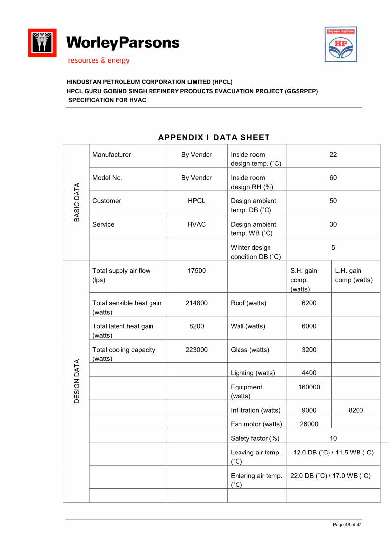
HINDUSTAN PETROLEUM CORPORATION LIMITED (HPCL)
HPCL GURU GOBIND SINGH REFINERY PRODUCTS EVACUATION PROJECT (GGSRPEP)
SPECIFICATION FOR HVAC
Page 46 of 47
APPENDIX I DATA SHEET
Manufacturer By Vendor Inside room
design temp. (˚C)
22
Model No. By Vendor Inside room
design RH (%)
60
Customer HPCL Design ambient
temp. DB (˚C)
50
Service HVAC Design ambient
temp. WB (˚C)
30
BASIC DATA
Winter design
condition DB (˚C)
5
Total supply air flow
(lps)
17500 S.H. gain
comp.
(watts)
L.H. gain
comp (watts)
Total sensible heat gain
(watts)
214800 Roof (watts) 6200
Total latent heat gain
(watts)
8200 Wall (watts) 6000
Total cooling capacity
(watts)
223000 Glass (watts) 3200
Lighting (watts) 4400
Equipment
(watts)
160000
Infiltration (watts) 9000 8200
Fan motor (watts) 26000
Safety factor (%) 10
Leaving air temp.
(˚C)
12.0 DB (˚C) / 11.5 WB (˚C)
Entering air temp.
(˚C)
22.0 DB (˚C) / 17.0 WB (˚C)
DESIGN DATA
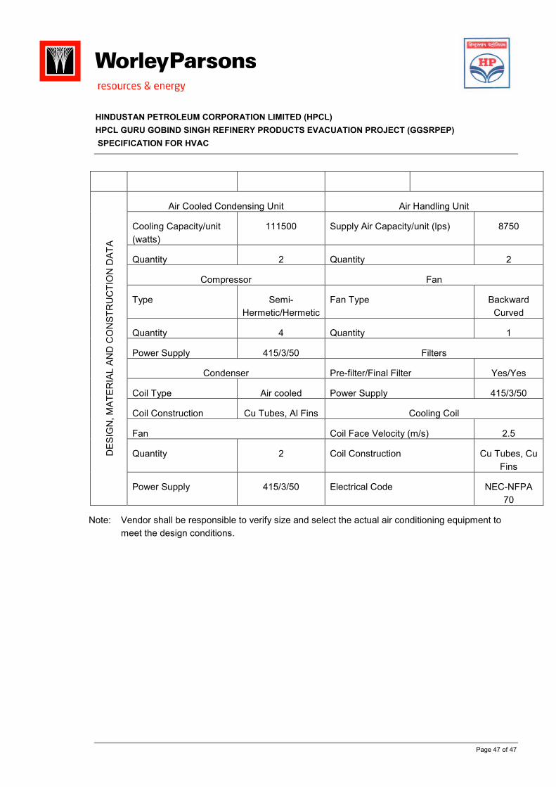
HINDUSTAN PETROLEUM CORPORATION LIMITED (HPCL)
HPCL GURU GOBIND SINGH REFINERY PRODUCTS EVACUATION PROJECT (GGSRPEP)
SPECIFICATION FOR HVAC
Page 47 of 47
Air Cooled Condensing Unit Air Handling Unit
Cooling Capacity/unit
(watts)
111500 Supply Air Capacity/unit (lps) 8750
Quantity 2 Quantity 2
Compressor Fan
Type Semi-
Hermetic/Hermetic
Fan Type Backward
Curved
Quantity 4 Quantity 1
Power Supply 415/3/50 Filters
Condenser Pre-filter/Final Filter Yes/Yes
Coil Type Air cooled Power Supply 415/3/50
Coil Construction Cu Tubes, Al Fins Cooling Coil
Fan Coil Face Velocity (m/s) 2.5
Quantity 2 Coil Construction Cu Tubes, Cu
Fins
DESIGN, MATERIAL AND CONSTRUCTION DATA
Power Supply 415/3/50 Electrical Code NEC-NFPA
70
Note: Vendor shall be responsible to verify size and select the actual air conditioning equipment to
meet the design conditions.
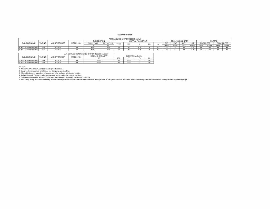
SUPPLY AIR EXT. ST. PR EAT EAT LAT LAT
L/s Pa DBºC WBºC DBºC WBºC TYPE % EFF TYPE % EFF
SUBSTATION BUILDING TBA NOTE 2 TBA 8750 TBA TEFC 60 415 3 50 22 17 12 11.5 PF 60 BF 95
SUBSTATION BUILDING TBA NOTE 2 TBA 8750 TBA TEFC 60 415 3 50 22 17 12 11.5 PF 60 BF 95
KW V Ph Hz
SUBSTATION BUILDING TBA NOTE 2 TBA 60 415 3 50
SUBSTATION BUILDING TBA NOTE 2 TBA 60 415 3 50
NOTES:-
1. Where "TBA" is shown, Contractor is to provide details.
2. Equipment manufacturer shall be as per Company approved list.
3. All electrical power capacities estimated are to be updated with Vendor details.
4. Air handling unit Vendor to select condensing unit to match the cooling coil duty.
5. The Contractor/Vendor is to confirm all equipment selection to satisfy the design conditions.
6. All ducting, piping and other necessary accessories required for complete satisfactory installation and operation of the system shall be estimated and confirmed by the Contractor/Vendor during detailed engineering stage.
111.5
111.5
EQUIPMENT LIST
FAN SECTION
Hz
AIR COOLED CONDENSING UNIT SCHEDULE (ACCU)
PRE-FILTER FINAL-FILTERBUILDING NAME TAG NO.
ELECTRICAL DATABUILDING NAME TAG NO. MANUFACTURER MODEL NO.
COOILNG CAPACITY
KW
KW V Ph
AIR HANDLING UNIT SCHEDULE (AHU)
SUPPLY FAN MOTOR COOLING COIL DATA FILTERS
MANUFACTURER MODEL NO.TYPE