
WORLDWIDE COMMERCIAL & CONSUMER … · Introduction - 1 INTRODUCTION Introduction Using Your...
22
OMLVU23003 C0 JOHN DEERE WORLDWIDE COMMERCIAL & CONSUMER EQUIPMENT DIVISION Original Instruction All information, illustrations and specifications in this manual are based on the latest information at the time of publication. The right is reserved to make changes at any time without notice. COPYRIGHT© 2010 Deere & Co. John Deere Worldwide Commercial and Consumer Equipment Division All rights reserved Previous Editions COPYRIGHT© 2008 LVU23003 C0 45 Gallon Sprayer LP20840, LP22886 OPERATOR’S MANUAL North American Version Litho in U.S.A.
Transcript of WORLDWIDE COMMERCIAL & CONSUMER … · Introduction - 1 INTRODUCTION Introduction Using Your...

JOHN DEEREWORLDWIDE COMMERCIAL & CONSUMER
EQUIPMENT DIVISION
LVU23003
C0
45 Gallon SprayerLP20840, LP22886
OMLVU23003 C0
OPERATOR’S MANUAL
Original InstructionAll information, illustrations and
specifications in this manual are based on the latest information at the time of
publication. The right is reserved to make changes at any time without notice.
COPYRIGHT© 2010Deere & Co.
John Deere Worldwide Commercial and Consumer Equipment Division
All rights reservedPrevious Editions
COPYRIGHT© 2008
North American VersionLitho in U.S.A.

INTRODUCTION
IntroductionUsing Your Operator’s ManualRead this entire operator’s manual, especially the safety information, before operating.
This manual is an important part of your machine. Keep all manuals in a convenient location so they can be accessed easily.
Use the safety and operating information in the attachment operator’s manual, along with the machine operator’s manual, to operate and service the attachment safely and correctly.
If your attachment manual has a section called Preparing the Machine, it means that you will have to do something to your tractor or vehicle before you can install the attachment. The Assembly and Installation sections of this manual provide information to assemble and install the attachment to your tractor or vehicle. Use the Service section to make any needed adjustments and routine service to your attachment.
If you have any questions or concerns with the assembly, installation, or operation of this attachment, see your local John Deere dealer or call the John Deere Customer Contact Center at 1-800-537-8233 for assistance.
Warranty information on this John Deere attachment can be found in the warranty that came with your John Deere tractor or vehicle.
Product IdentificationProduct CompatibilityThis Category 1, Three-Point Hitch Mounted Sprayer is compatible with Compact Utility Tractors, and X400, X500 and X700 Ultimate Series Garden Tractors.
Contact your John Deere dealer for compatibility and installation information for any Compact Utility Tractor not included in this manual.
Safety LabelsUnderstanding The Machine Safety LabelsThe machine safety labels shown in this section are placed in important areas on your machine to draw attention to potential safety hazards.
On your machine safety labels, the words DANGER, WARNING, and CAUTION are used with this safety-alert symbol. DANGER identifies the most serious hazards.
The operator’s manual also explains any potential safety hazards whenever necessary in special safety messages that are identified with the word, CAUTION, and the safety-alert symbol.
There can be additional safety information contained on parts and components sourced from suppliers that is not reproduced in this operator’s manual.
Safety Label Location
MX44576
A- WARNING M147712
B- CAUTION M117627
WARNING M147712
M147712a
• To avoid injury from chemical hazards, wear protective clothing. Read and follow chemical manufacturer’s labels and instructions.
CAUTION M117627
M117627
• Avoid injury from loss of braking or steering. Install ballast per operator’s manual.
SafetyRead Safety in Machine Operator’s ManualRead the general safety operating precautions in your machine operator’s manual for additional safety information.
Operate Safely
• Read the machine and attachment operator’s manual carefully. Be thoroughly familiar with the controls and the proper use of the equipment. Know how to stop the machine and disengage the controls quickly.
• Do not let children or an untrained person operate machine.
• Make any necessary adjustments before you operate. Never attempt to make any adjustments while the engine is running, unless if
BA
Introduction - 1

SAFETY
recommended in adjustment procedure.• Take all possible precautions when leaving the machine unattended. Shut off the engine before making any repairs, adjustments, or inspections. Lower the attachment, lock the parking brake, stop the engine, and remove the key.
• Look behind machine before you back up. Back up carefully.
• Do not let anyone, especially children, ride on machine or attachment. Riders are subject to injury such as being struck by foreign objects and being thrown off. Riders may also obstruct the operator’s view, resulting in the machine being operated in an unsafe manner.
• Use only attachments and accessories approved by the manufacturer of this product.
• If the machine vibrates abnormally, stop the engine and check immediately for the cause. Vibration is generally a warning of trouble.
• Always refer to the Storage section of the operator’s manual for important details if storing this product for a long period of time.
• Keep people and pets out of the work area. Stop machine if anyone enters the area.
• If you hit an object, stop the machine and inspect it. Make repairs before you operate. Keep machine properly maintained and in good working order. Keep all shields and guards in place.
• Always inspect the sprayer completely before and after each use. Before pressurizing the system, check to be sure all fittings and hoses are tightly installed. Be sure guards and shields are in good condition and fastened in place. Make any necessary adjustments before you operate.
• Never use the sprayer during windy conditions.
• Always release pressure in the system before filling, cleaning or servicing the sprayer.
• Do not put nozzle tip or other sprayer parts to your lips to blow out dirt. Use compressed air.
• If the sprayer is mounted to the bed of a utility vehicle, never raise the bed with the sprayer installed. Empty the sprayer and remove it from the bed if you need to raise the bed for any reason.
Parking Safely
1. Stop vehicle on a level surface, not on a slope.
2. Lock park brake.
3. Stop engine.
4. Remove key.
5. Before you leave the operator’s seat, wait for engine and all moving parts to stop.
6. Disconnect the negative battery cable or remove the spark plug wire (for gasoline engines) before servicing the machine.
Mix and Handle Chemicals Safely
• It is best to wear full cover clothing and always wear protective goggles and rubber gloves to protect yourself while handling chemicals.
• Follow instructions on chemical container labels.
• Open all chemical containers carefully, using proper tools.
• Open, pour, weigh and mix chemicals in a well-ventilated area.
• Reserve all equipment used for the application of chemicals exclusively for that purpose.
• Prohibit all smoking, drinking and eating food in chemical-handling area.
• It is a good practice to take a soapy shower immediately after the using
the sprayer to apply chemicals.
• Wash all clothing worn when using chemicals separately in the laundry after spraying is completed.
Read Chemical Container Label
• Chemicals can be dangerous. Improper selection or use can injure persons, animals, plants, soils or other property. Select the right chemical for the job and handle and apply with care.
• Read the instructions, precautions, and warnings on the container label before opening. Use the product strictly according to label directions for specific applications, in the amounts specified, at the times specified and only when needed.
• Keep the container closed tightly except when preparing the mix.
• Do not remove labels from chemical containers. Store all chemicals in their original containers.
• Do not mix chemicals unless stated on the container label.
• Store chemicals when not in use according to the container label.
Handle Chemical Products Safely
• Direct exposure to hazardous chemicals can cause serious injury. Potentially hazardous chemicals used with John Deere equipment include pesticides, herbicides and fungicides.
• A Material Safety Data Sheet (MSDS) provides specific details on chemical products: physical and health hazards, safety procedures, and emergency response techniques.
• The MSDS should be obtained from the chemical dealer at the time of the chemical purchase.
• Check the MSDS before beginning any job using a hazardous chemical. Know exactly what the risks are and how to do the job safely. Always wear recommended personal protection equipment.
Practice Safe Maintenance
• Only qualified, trained adults should service this machine.
• Understand service procedure before doing work. Keep area clean and dry.
• Do not operate the engine in a confined space where dangerous carbon monoxide fumes can collect.
• Never lubricate, service or adjust the machine or attachment while it is moving. Keep safety devices in place and in working condition. Keep hardware tight.
• Keep hands, feet, clothing, jewelry, and long hair away from any moving parts, to prevent them from getting caught.
• Lower any attachment completely to the ground or to an existing attachment mechanical stop before servicing the attachment. Disengage all power and stop the engine. Lock park brake and remove the key. Let machine cool.
• Disconnect battery or remove spark plug wire (for gasoline engines) before making any repairs.
• Before servicing machine or attachment, carefully release pressure from any components with stored energy, such as hydraulic components and springs.
• Release hydraulic pressure by lowering attachment or cutting units to the ground or to a mechanical stop and move hydraulic control levers.
• Securely support any machine or attachment elements that must be raised for service work. Use jack stands or lock service latches to support components when needed.
Safety - 2
ASSEMBLY
• Never run engine unless park brake is locked.• Keep all parts in good condition and properly installed. Fix damage immediately. Replace worn or broken parts. Replace all worn or damaged safety and instruction decals.
• Check all hardware at frequent intervals to be sure the equipment is in safe working condition.
• Do not modify machine or safety devices. Unauthorized modifications to the machine or attachment may impair its function and safety.
Wear Appropriate Clothing
• Wear close fitting clothing and safety equipment appropriate for the job.
• Certain operating conditions may dictate that the operator and any passenger wear
appropriate safety equipment while operating the vehicle. Be prepared for any existing and potential conditions before operating machine.
• Local safety or insurance regulations may require additional safety equipment such as eye protection or a hard hat.
• Always wear substantial footwear and long trousers. Do not operate the equipment when barefoot or wearing open sandals.
• Wear proper clothing and safety equipment while handling chemicals or using the sprayer. Refer to the MSDS for the chemicals being used to be sure the proper personal protection equipment is being used.
Avoid High Pressure Fluids
• Hydraulic hoses and lines can fail due to physical damage, kinks, age, and exposure. Check hoses and lines regularly. Replace damaged hoses and lines.
• Hydraulic fluid connections can loosen due to physical damage and vibration. Check connections regularly. Tighten loose connections.
• Escaping fluid under pressure can penetrate the skin causing serious injury. Avoid the hazard by relieving pressure before disconnecting hydraulic or other lines. Tighten all connections before applying pressure.
• Search for leaks with a piece of cardboard. Protect hands and body from high pressure fluids.
• If an accident occurs, see a doctor immediately. Any fluid injected into the skin must be surgically removed within a few hours or gangrene may result. Doctors unfamiliar with this type of injury should reference a knowledgeable medical source. Such information is available from Deere & Company Medical Department in Moline, Illinois, U.S.A. Information may be obtained in the United States and Canada only by calling 1-800-822-8262.
Dispose of Chemicals Properly
• Proper disposal of excess spray material is very important. If you have excess tank solution, it is best to dilute it with water and apply it to the area you previously treated.
• Never dump solution into a drain or near a lake or stream.
• Chemicals containers should be triple-rinsed, with the rinse water added to the sprayer tank. Do not burn empty chemical containers. Dispose of containers at recycling centers.
Handling Waste Product and Chemicals Waste products, such as, used oil, fuel, coolant, brake fluid, and batteries, can harm the environment and people:
• Do not use beverage containers for waste fluids - someone may drink from them.
• See your local Recycling Center or authorized dealer to learn how to recycle or get rid of waste products.
• A Material Safety Data Sheet (MSDS) provides specific details on chemical products: physical and health hazards, safety procedures, and emergency response techniques. The seller of the chemical products used with your machine is responsible for providing the MSDS for that product.
AssemblyParts
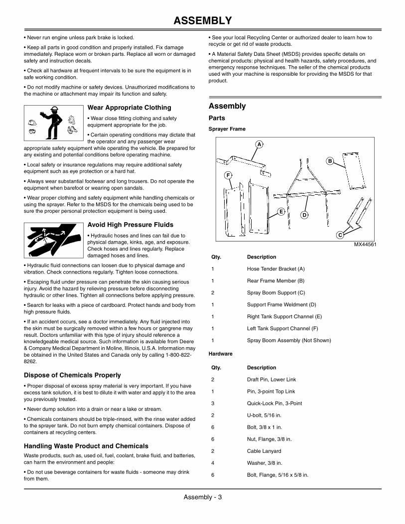
Sprayer Frame
MX44561
Hardware
Qty. Description
1 Hose Tender Bracket (A)
1 Rear Frame Member (B)
2 Spray Boom Support (C)
1 Support Frame Weldment (D)
1 Right Tank Support Channel (E)
1 Left Tank Support Channel (F)
1 Spray Boom Assembly (Not Shown)
Qty. Description
2 Draft Pin, Lower Link
1 Pin, 3-point Top Link
3 Quick-Lock Pin, 3-Point
2 U-bolt, 5/16 in.
6 Bolt, 3/8 x 1 in.
6 Nut, Flange, 3/8 in.
2 Cable Lanyard
4 Washer, 3/8 in.
6 Bolt, Flange, 5/16 x 5/8 in.
B
C
DE
F
A
Assembly - 3

ASSEMBLY
Wire Harness
Boom Assembly
Optional LP22886 High Performance Spray Boom Assembly
MX44562
Assemble Sprayer
Assemble Frame and Secure Tank
MX44563
1. Install the draft pins (A) into the crossbar (B) and secure with jam nuts (C).
MX44564
2. Loosely install left (D) and right (E) tank support channels with six 3/8 x 1 in. bolts (F) and 3/8 in. flange nuts (G).
MX44565
3. Loosely install rear frame member (H) between tank support channels with four 5/16 x 3/4 in. flange head bolts (I) and 5/16 in. flange nuts.
16 Nut, Flange, 5/16 in.
8 Bolt, Flange, 5/16 x 3/4 in.
2 Jam Nut, Lower Link Draft Pin
2 Bolt, J-Shaped, 7 in.
2 Screw, 10/24 x 5/8 in. (Standard 3-Point only)
1 Pin, Hand Gun Mount (High Performance 3-Point only)
1 Hose Clamp (High Performance 3-Point only)
1 Hand Wand Clip (Large) (Standard 3-Point only)
1 Hand Wand Clip (Small) (Standard 3-Point only)
Qty. Description
1 Harness Extension, 24 in.
1 Harness Extension, 8 ft.
8 Tie Wrap
1 Switched Harness
1 Auxiliary Power Connector
Qty. Description
1 Folding Boom Assembly, Standard 120 in.
Qty. Description
1 Folding Boom Assembly, Precision 150 in. (H) (High Performance 3-Point only)
1 Spray Nozzles, Boomless (I) (High Performance 3-Point only)
Qty. Description
IH
A A
C C
B
D
E
G
F
I
I
H
Assembly - 4
ASSEMBLY
MX44566
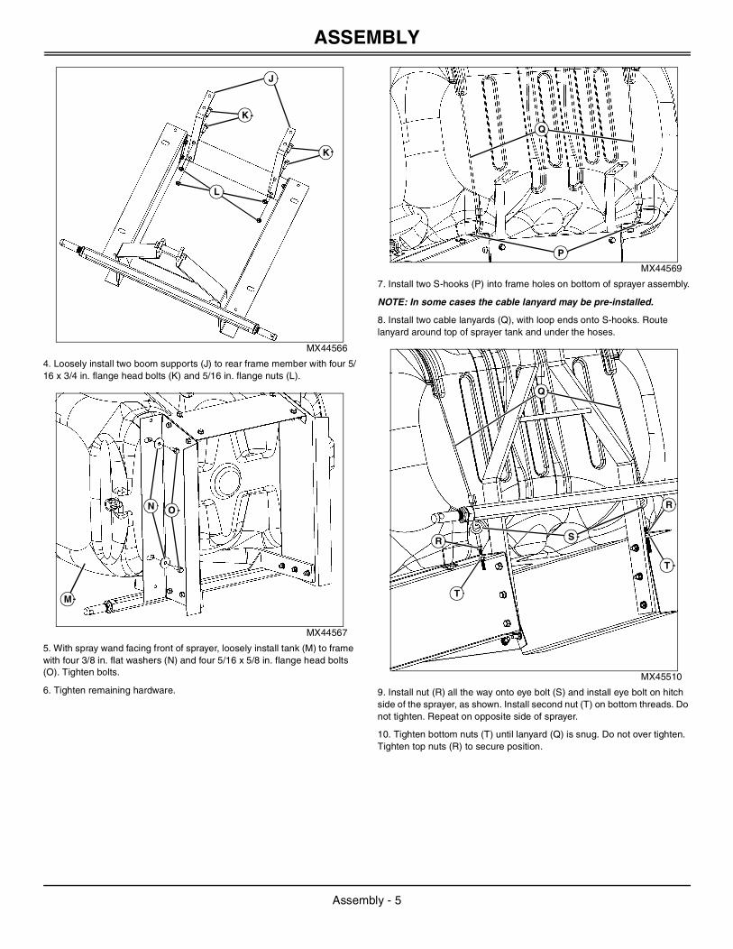
4. Loosely install two boom supports (J) to rear frame member with four 5/16 x 3/4 in. flange head bolts (K) and 5/16 in. flange nuts (L).
MX44567
5. With spray wand facing front of sprayer, loosely install tank (M) to frame with four 3/8 in. flat washers (N) and four 5/16 x 5/8 in. flange head bolts (O). Tighten bolts.
6. Tighten remaining hardware.
MX44569
7. Install two S-hooks (P) into frame holes on bottom of sprayer assembly.
NOTE: In some cases the cable lanyard may be pre-installed.
8. Install two cable lanyards (Q), with loop ends onto S-hooks. Route lanyard around top of sprayer tank and under the hoses.
MX45510
9. Install nut (R) all the way onto eye bolt (S) and install eye bolt on hitch side of the sprayer, as shown. Install second nut (T) on bottom threads. Do not tighten. Repeat on opposite side of sprayer.
10. Tighten bottom nuts (T) until lanyard (Q) is snug. Do not over tighten. Tighten top nuts (R) to secure position.
J
K
L
K
M
N O
P
Q
Q
S
T
T
R
R
Assembly - 5
ASSEMBLY
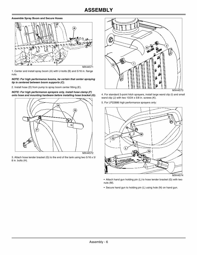
Assemble Spray Boom and Secure HosesMX44571
1. Center and install spray boom (A) with U-bolts (B) and 5/16 in. flange nuts.
NOTE: For high performance booms, be certain that center spraying tip is centered between boom supports (C).
2. Install hose (D) from pump to spray boom center fitting (E).
NOTE: For high performance sprayers only, install hose clamp (F) onto hose and mounting hardware before installing hose bracket (G).
MX44572
3. Attach hose tender bracket (G) to the end of the tank using two 5/16 x 5/8 in. bolts (H).
MX44573
4. For standard 3-point hitch sprayers, install large wand clip (I) and small wand clip (J) with two 10/24 x 5/8 in. screws (K).
5. For LP22886 high performance sprayers only:
MX44574
• Attach hand gun holding pin (L) to hose tender bracket (G) with two nuts (M).
• Secure hand gun to holding pin (L) using hole (N) on hand gun.
ED
C
A
B
G
H
F
I
JK
K
LN
G
M
Assembly - 6

INSTALLING
InstallingInstalling Ballast
Garden Tractors
Required ballast:
• Four front suitcase weights, 18kg (40 lb) each.
Recommended ballast:
NOTE: Certain working conditions may be improved by increasing front ballast.
• Install additional front suitcase weights.
• Install wheel weights on front wheels.
Compact Utility Tractors
See Ballasting Machine in your tractor operator’s manual to determine the number of front weights required to ballast the tractor.
Add ballast for an implement code of 19.
Use the following table to ballast these tractor models:
Attaching Sprayer to Tractor
1. Park machine safely. (See Parking Safely in Safety section.)
2. Lower the 3-point hitch.
MX26345
3. Slide the lower 3-point hitch arms (A and B) over the lower link draft pins (C). Secure using two quick-lock pins (D).
4. Connect the center link (E) to the sprayer upper mounting point using the top link pin (F) and one quick-lock pin (G).
MX26346
5. Connect the wiring harness (H) to the pump.
c CAUTION: Avoid injury! Machine can become unstable when operating with attachment. Ballast is required when the attachment is installed.
When the attachment is removed, also remove any ballast that was added to the machine.
Use only attachments and accessories recommended by the manufacturer.
Tractor Model Number of 42 lb. (20 kg) Weights
2305 with 3-Point Hitch 4
2305 with I-Match Hitch 5
2320 with 3-Point Hitch 1
2320 with I-Match Hitch 2
2520 with 3-Point Hitch 0
2520 with I-Match Hitch 0
CA
B
D
GE
F
H
Installing - 7
PREPARING VEHICLE
MX26347
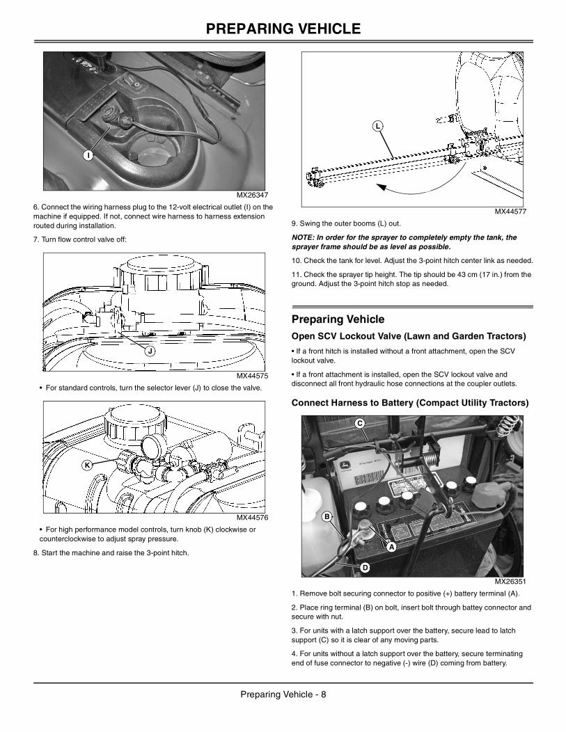
6. Connect the wiring harness plug to the 12-volt electrical outlet (I) on the machine if equipped. If not, connect wire harness to harness extension routed during installation.
7. Turn flow control valve off:
MX44575
• For standard controls, turn the selector lever (J) to close the valve.
MX44576
• For high performance model controls, turn knob (K) clockwise or counterclockwise to adjust spray pressure.
8. Start the machine and raise the 3-point hitch.
MX44577
9. Swing the outer booms (L) out.
NOTE: In order for the sprayer to completely empty the tank, the sprayer frame should be as level as possible.
10. Check the tank for level. Adjust the 3-point hitch center link as needed.
11. Check the sprayer tip height. The tip should be 43 cm (17 in.) from the ground. Adjust the 3-point hitch stop as needed.
Preparing VehicleOpen SCV Lockout Valve (Lawn and Garden Tractors)
• If a front hitch is installed without a front attachment, open the SCV lockout valve.
• If a front attachment is installed, open the SCV lockout valve and disconnect all front hydraulic hose connections at the coupler outlets.
Connect Harness to Battery (Compact Utility Tractors)
MX26351
1. Remove bolt securing connector to positive (+) battery terminal (A).
2. Place ring terminal (B) on bolt, insert bolt through battey connector and secure with nut.
3. For units with a latch support over the battery, secure lead to latch support (C) so it is clear of any moving parts.
4. For units without a latch support over the battery, secure terminating end of fuse connector to negative (-) wire (D) coming from battery.
I
J
K
L
A
B
C
D
Preparing Vehicle - 8

PREPARING VEHICLE
Tractor Model 2305
1. Park machine safely. (See Parking Safely in Safety section.)
MX26352
2. Route harness (A) under radiator and secure in place with tie wrap (B), passing through opening where radiator drain passes.
3. Secure harness to tractor frame with tie wraps (C).
MX26914
4. Route harness (D) along frame and secure between hydraulic lines with tie wrap (E) at rear of tractor.
MX26915
5. Loop excess wire and secure to fender mount with tie wrap (F).
Tractor Models 2320, 2520
1. Park machine safely. (See Parking Safely in Safety section.)
MX26916
2. Pull back radiator and engine seals (A). Position wire harness (B) in gap under firewall. Push seals back into place.
3. Secure harness to below radiator with tie wrap (C).
MX26917
4. Secure harness to coolant line with tie wrap (D).
MX26918
5. Route harness along coolant line. Secure to hydraulic lines behind SCV coupler bracket with two tie wraps (E).
AB
C
D
E
F
AB
A
C
D
E
Preparing Vehicle - 9
PREPARING VEHICLE
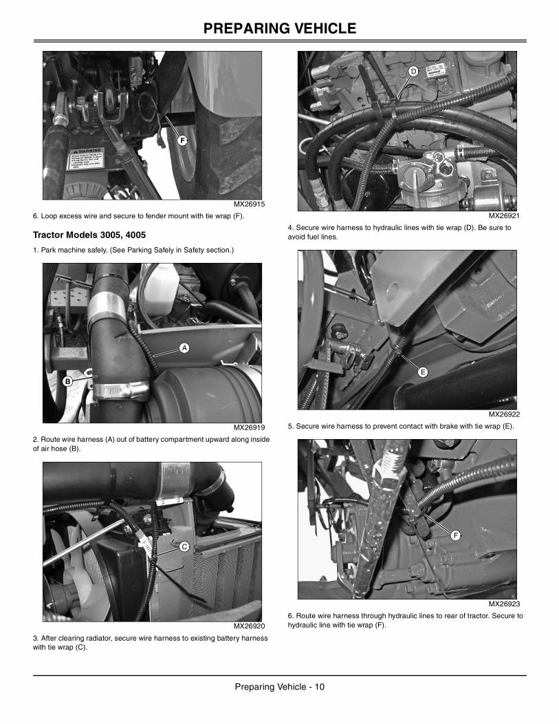
MX26915
6. Loop excess wire and secure to fender mount with tie wrap (F).
Tractor Models 3005, 4005
1. Park machine safely. (See Parking Safely in Safety section.)
MX26919
2. Route wire harness (A) out of battery compartment upward along inside of air hose (B).
MX26920
3. After clearing radiator, secure wire harness to existing battery harness with tie wrap (C).
MX26921
4. Secure wire harness to hydraulic lines with tie wrap (D). Be sure to avoid fuel lines.
MX26922
5. Secure wire harness to prevent contact with brake with tie wrap (E).
MX26923
6. Route wire harness through hydraulic lines to rear of tractor. Secure to hydraulic line with tie wrap (F).
F
A
B
C
D
E
F
Preparing Vehicle - 10

PREPARING VEHICLE
MX26924
7. Secure end of wire harness to existing harnesses with tie wrap (G), at rear of tractor.
Tractor Models 3203, 3120-3720
1. Park machine safely. (See Parking Safely in Safety section.)
MX26925
2. Pull back radiator and engine seals (A). Position wire harness (B) in gap under firewall. Push seals back into place.
MX26926
3. Secure wire harness with two tie wraps (C) at engine compartment.
MX26927
4. Secure wire harness under floor to hydraulic lines with tie wrap (D).
MX26928
5. Route along hydraulic lines toward rear of tractor. Secure with tie wrap (E).
G
B
A
C
D
E
Preparing Vehicle - 11

PREPARING VEHICLE
MX26929
6. Secure end of wire harness to hydraulic line at rear of tractor with tie wrap (F).
MX26930
7. Tractor with cab: Install plug connector in auxiliary power port (G).
Tractor Model 4105
1. Park machine safely. (See Parking Safely in Safety section.)
MX26931
2. Route wire harness (A) through gap at bottom of front grille and radiator.
MX26932
3. Secure wire harness at engine compartment with two tie wraps (B).
MX26933
4. Secure wire harness to hydraulic lines with tie wraps (C).
MX26935
5. Route wire harness along hydraulic lines to rear of tractor and secure with two tie wraps (D).
F
G
A
B
C
DD
Preparing Vehicle - 12

REMOVING AND STORING
MX26936
6. Secure end of wire harness to hydraulic line at rear of tractor with tie wrap (E).
Tractor Models 4120-4720
1. Park machine safely. (See Parking Safely in Safety section.)
MX26937
2. Pull rubber seal (A) from bottom corner of radiator shield and thread wire (B) through gap.
MX26938
3. Secure harness with two tie wraps (C) at engine compartment.
MX26939
4. Secure wire harness to hydraulic lines with two tie wraps (D).
MX26940
5. Route along hydraulic lines to rear of tractor. Secure with tie wrap (E).
MX26941
6. Secure wire harness to rear hydraulic line with tie wrap (F) and at rear of tractor with tie wrap (G).
Removing and StoringRemoving Sprayer From Tractor
1. Park the machine safely. (See Parking Safely in Safety section.)
E
A
B
CC
D
D
E
G
F
Removing and Storing - 13

REMOVING AND STORING
2. Empty the sprayer tank.3. Lower the sprayer to the ground.
4. Disconnect the wiring harness from the 12 volt outlet on the machine.
5. Roll up the wiring harness and store with sprayer.
MX44635
6. Fold in the outer booms (A and B).
MX26345
7. Remove the quick-lock pin (C) and top link pin (D), and disconnect the center link (E).
8. Install the link pin (D) and quick-lock pin (C) in the sprayer top mounting hole for storage.
9. Remove the quick-lock pins (F) from the lower 3-point hitch arms.
10. Pull the lower 3-point hitch arms (G and H) off the lower link draft pins (I).
11. Install the quick-lock pins (F) into the lower link draft pins (I) for
storage.
12. Move the sprayer away from the machine.
13. Remove any added front ballast from machine.
Store Sprayer Safely
1. Pump all spray material from tank. (See Dispose of Chemicals Properly in the SAFETY section.)
2. Rinse tank, pump, spray wand and all hoses thoroughly with fresh clean water.
3. Repeat step 2 several times.
4. Wipe out sump with a clean cloth or paper towel.
5. Drain hoses and pump filter.
6. Check sprayer for worn or damaged parts. Replace parts as needed.
7. Tighten loose hardware.
8. Store sprayer in a place where it will not freeze.
A
B
IG
H
F
CE
D
c CAUTION: Avoid injury! Machine can become unstable when operating with attachment. Ballast is required when the attachment is installed.
When the attachment is removed, also remove any ballast that was added to the machine.
Use only attachments and accessories recommended by the manufacturer.
c CAUTION: Avoid injury! To avoid chemical injury:
• Wear protective clothes, gloves and goggles when handling sprayer.
• Do not store sprayer with chemicals in tank.
• If spray comes in contact with your body, immediately follow directions on chemical container pertaining to spray material.
Removing and Storing - 14
OPERATING
OperatingFilling Sprayer Tank
1. Clean area around tank filler cap to prevent tank contamination.
2. Remove tank filler cap and fill tank.
3. Install tank filler cap.
Draining and Cleaning Sprayer Tank
1. The preferred method of cleaning is to dilute remaining material with water and apply it to the area previously treated:
• If excess material remains, remove drain cap and empty remaining material into an appropriate container for reuse or for disposal according to local regulations or as specified in the manufacturer’s label.
NOTE: Be sure to visibly label the container contents for safety.
2. Spray all inside surfaces of tank with low pressure garden hose to remove any remaining solution. Replace the drain cap and run clean water through the pump, hoses and boom applying those contaminated contents on previously treated area.
3. Rinse outside of sprayer tank thoroughly with fresh clean water. Rinse several times to make sure sprayer tank is clean and free of chemicals.
4. Once the tank is empty, wipe out inside of sprayer tank with a clean cloth or paper towel.
5. Install drain cap and filler cap.
Calibrating the SprayerWhen spraying with boom, sprayer must be calibrated to ensure proper spray coverage and to combat over-application or under-application. The calibration process is simplified when broken into three steps:
• calculate speed of tractor
• determine nozzle size and consult calibration chart for desired or instructed gallon per acre (GPA)
• set pressure using relief valve
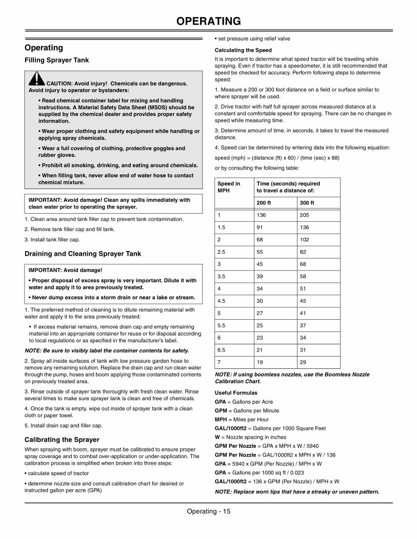
Calculating the Speed
It is important to determine what speed tractor will be traveling while spraying. Even if tractor has a speedometer, it is still recommended that speed be checked for accuracy. Perform following steps to determine speed:
1. Measure a 200 or 300 foot distance on a field or surface similar to where sprayer will be used.
2. Drive tractor with half full sprayer across measured distance at a constant and comfortable speed for spraying. There can be no changes in speed while measuring time.
3. Determine amount of time, in seconds, it takes to travel the measured distance.
4. Speed can be determined by entering data into the following equation:
speed (mph) = (distance (ft) x 60) / (time (sec) x 88)
or by consulting the following table:
NOTE: If using boomless nozzles, use the Boomless Nozzle Calibration Chart.
Useful Formulas
GPA = Gallons per Acre
GPM = Gallons per Minute
MPH = Miles per Hour
GAL/1000ft2 = Gallons per 1000 Square Feet
W = Nozzle spacing in inches
GPM Per Nozzle = GPA x MPH x W / 5940
GPM Per Nozzle = GAL/1000ft2 x MPH x W / 136
GPA = 5940 x GPM (Per Nozzle) / MPH x W
GPA = Gallons per 1000 sq ft / 0.023
GAL/1000ft2 = 136 x GPM (Per Nozzle) / MPH x W
NOTE: Replace worn tips that have a streaky or uneven pattern.
c CAUTION: Avoid injury! Chemicals can be dangerous. Avoid injury to operator or bystanders:
• Read chemical container label for mixing and handling instructions. A Material Safety Data Sheet (MSDS) should be supplied by the chemical dealer and provides proper safety information.
• Wear proper clothing and safety equipment while handling or applying spray chemicals.
• Wear a full covering of clothing, protective goggles and rubber gloves.
• Prohibit all smoking, drinking, and eating around chemicals.
• When filling tank, never allow end of water hose to contact chemical mixture.
IMPORTANT: Avoid damage! Clean any spills immediately with clean water prior to operating the sprayer.
IMPORTANT: Avoid damage!
• Proper disposal of excess spray is very important. Dilute it with water and apply it to area previously treated.
• Never dump excess into a storm drain or near a lake or stream.
Speed in MPH
Time (seconds) required to travel a distance of:
200 ft 300 ft
1 136 205
1.5 91 136
2 68 102
2.5 55 82
3 45 68
3.5 39 58
4 34 51
4.5 30 45
5 27 41
5.5 25 37
6 23 34
6.5 21 31
7 19 29
Operating - 15

OPERATING
Determining Nozzle Size and Using Calibration Chart
The spray nozzles on your sprayer are TF-VP3, which match up with the calibration chart. Refer to the calibration chart. Using tractor speed, nozzle size, and desired gallons per acre (GPA), find pressure (psi) necessary to achieve your GPA. It is important to note that lower pressure settings will result in less spray drift.
NOTE: Lower pressure settings will result in less spray drift.
Example:
Assume tractor speed is determined to be 4 mph, nozzles are grey (TF-VP3), and desired GPA is 20 GPA. The calibration charts shows that you should set sprayer’s pressure at about 20 psi in order to apply 20 GPA.
NOTE: Optimum spray performance is achieved between 20-25 psi. When shutting off outer tips, use the regulator valve to adjust your boom pressure accordingly.
Boomless Calibration
Right and Left Nozzles: 1/4XP10R
Center Nozzle: TF-VP3
Drop Size: XC
Adjusting the Sprayer Pressure
NOTE: All calibration settings need to be completed and verified with clean water.
Once correct pressure setting has been determined, the sprayer must be adjusted to that pressure setting. Before adjusting sprayer’s pressure, it is important to set tractor RPM at rate that was used to determine tractor speed.
MX44575
1. LP20840 Standard 3-Point Hitch Sprayer: Although the pressure can be adjusted by partially opening the control valve (A), it is recommended that the valve be placed in the full open position.
• The standard boom is equipped with the TF-VP3 tips and sprays at approximately 20 PSI through the boom when the valve is in open position.
• For calibration purposes, adjust your speed for proper coverage.
GPM Seconds to collect 1 qt
GPM Seconds to collect 1 qt
0.05 300 0.20 75
0.06 250 0.23 67
0.07 214 0.25 60
0.08 188 0.30 50
0.09 167 0.35 40
0.10 150 0.40 35
0.11 136 0.50 30
0.12 125 0.60 25
0.13 115 0.70 20
0.14 107 0.80 18
0.15 100 0.90 17
0.17 80 1.00 15
IMPORTANT: Avoid damage! When switching from one chemical to another chemical in the sprayer where contamination must be prevented, wash out with tank cleaner and water throughout the tank, pump, and all hoses. Also flush with water two to three times. Herbicides such as 2-4D are hard to remove. Follow instructions on procedures noted on all labels.
STANDARD / PRECISION BOOM
Tip Size PSI GPM one nozzle
GPA 30 in. Spacing
2 MPH 3 MPH 4 MPH 5 MPH
TF-VP3 10 0.30 29.70 19.80 14.85 11.88
20 0.42 41.58 27.72 20.79 16.63
30 0.52 51.48 34.32 25.74 20.59
40 0.60 59.40 39.60 29.70 23.76
BOOMLESS CALIBRATION CHART FOR 24” HEIGHT
PSI Cap. 3 Nozzle GPM
Spray Width “ft”
GPA
4 mph 6 mph 8 mph 10 mph
20 1.84 23 10.5
30 2.26 25 11.2 6.5 5.6 4.5
40 2.60 28 11.9 7.9 6.0 4.8
BOOMLESS CALIBRATION CHART FOR 36” HEIGHT
PSI Cap. 3 Nozzle GPM
Spray Width “ft”
GPA
4 mph 6 mph 8 mph 10 mph
20 1.84 25 10..1 6.6 5.0 3.8
30 2.26 28 10.4 6.9 5.2 4.1
40 2.60 30 10.7 7.2 5.4 4.3
A
7.1 5.1 4.2
Operating - 16
OPERATING
MX44576
2. LP22886 High Performance 3-Point Hitch Sprayer: The relief valve (B) controls the sprayer's pressure and is located directly beside the pressure gauge (C). Before you use sprayer, turn the relief valve until you achieve the necessary pressure.
NOTE: Optimum spray performance is achieved between 20-25 psi. When shutting off outer tips, use the regulator valve to adjust your boom pressure accordingly.
Starting and Stopping Sprayer
MX44575
1. LP20840 Standard 3-Point Hitch Sprayer: Turn the selector lever (A) on the sprayer to the desired position, handgun or spray boom. To stop flow to the spray nozzles, turn the lever to the OFF position.
• The arrow on the handle of the valve indicates the direction material will flow.
MX44576
2. LP22886 High Performance 3-Point Hitch Sprayer:
• Turn knob (B) Clockwise to control the pressure and recirculation. Turn handle counterclockwise to recirculate more material to the tank and adjust pressure to boom or wand.
• Use valve (C) to route spray to spray gun or boom. The direction the handle is pointing is the direction of flow.
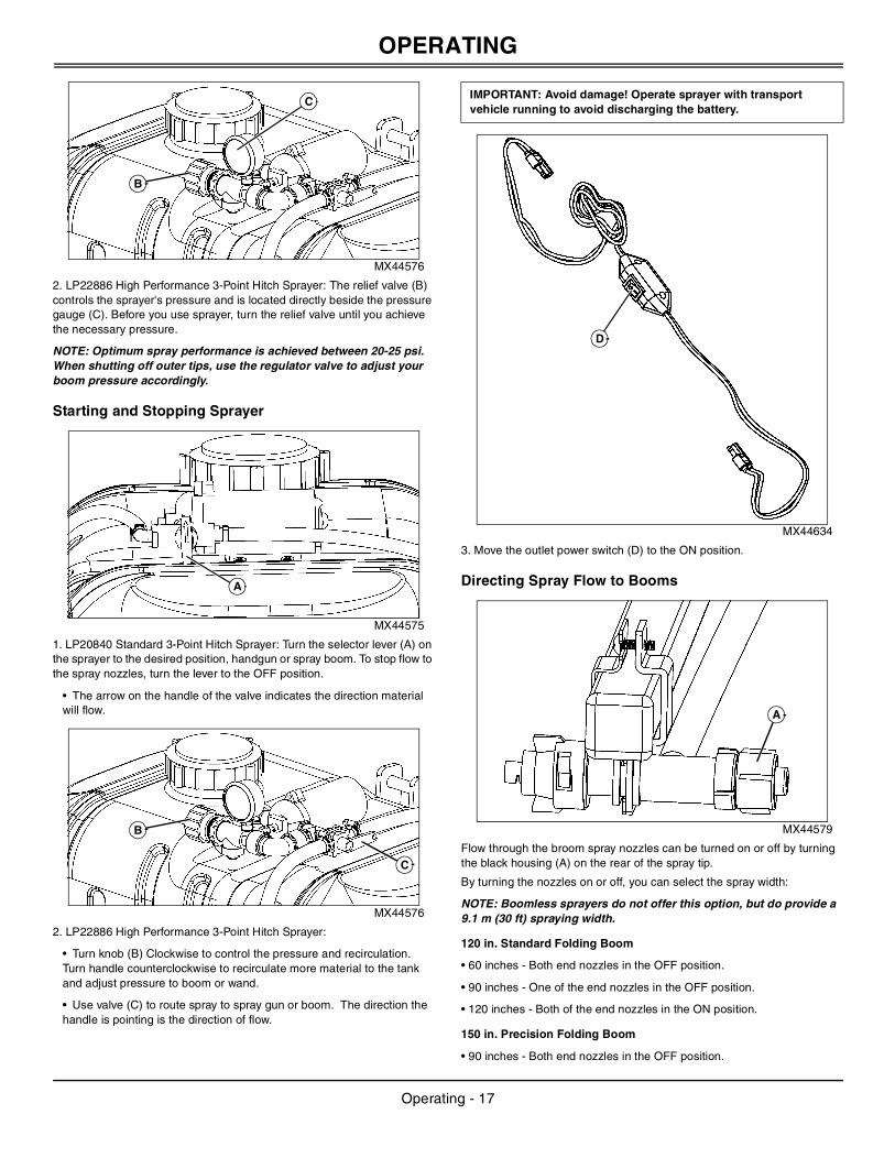
MX44634
3. Move the outlet power switch (D) to the ON position.
Directing Spray Flow to Booms
MX44579
Flow through the broom spray nozzles can be turned on or off by turning the black housing (A) on the rear of the spray tip.
By turning the nozzles on or off, you can select the spray width:
NOTE: Boomless sprayers do not offer this option, but do provide a 9.1 m (30 ft) spraying width.
120 in. Standard Folding Boom
• 60 inches - Both end nozzles in the OFF position.
• 90 inches - One of the end nozzles in the OFF position.
• 120 inches - Both of the end nozzles in the ON position.
150 in. Precision Folding Boom
• 90 inches - Both end nozzles in the OFF position.
B
C
A
B
C
IMPORTANT: Avoid damage! Operate sprayer with transport vehicle running to avoid discharging the battery.
D
A
Operating - 17

SERVICE
• 120 inches - One of the end nozzles in the OFF position.• 150 inches - Both of the end nozzles in the ON position.
Using the Handgun
LP20840 Standard 3-Point Hitch Sprayer
1. Turn the selector lever to the handgun position.
NOTE: Removal of spray tip (A) allows for quick cleaning/rinsing of sprayer tank.
MX44578
2. Adjust nozzle:
• Nozzle Angle – Loosen locknut (B). Turn the nozzle tube (C) to the desired position and tighten the locknut.
• Nozzle Spray Pattern – To change the spray pattern, tighten or loosen nozzle (D) as desired.
3. Squeeze the handle (E) to spray.
4. Push lock (F) forward to lock handle in ON position.
LP22886 High Performance 3-Point Hitch Sprayer
1. Turn the selector lever to the handgun position.
MX43065
2. Squeeze the handle (A) to spray.
3. Adjust mist to stream using lever (B).
4. Spray guard (C) can be adjusted by loosening (D) and sliding spray guard to desired position. The spray guard is intended to keep overspray off of your hands.
5. Flip handle lock (E) forward to lock handle in ON position.
Spraying Tips
• Do not let sprayer run in one spot.
• Do not over spray when you use weed killers.
• Liquid spray material is recommended. Sprayer does not agitate wettable powders.
• Timely applications of a smaller dosage are better than large applications.
• Turn sprayer off during turns to avoid double spraying.
• Fill sprayer where spills cannot harm grass.
• Follow manufacturer's recommendations for application of specific chemicals.
• Stop sprayer when tank is empty.
ServiceServicing Sprayer Safely
Cleaning Spray Nozzle
MX44636
1. Remove spray nozzle (A) from sprayer.
2. Remove the spray tip (B) and gasket (C) from the spray nozzle (A).
3. Remove the screen (D) from the nozzle socket on the boom. Replace the screen if damaged.
4. Wash the screen (D) and spray tip (B) in a nonflammable solvent.
5. Align the flat side (F) of the spray tip with the flat on the opening of the spray nozzle (A), and install the spray tip into the nozzle.
NOTE: Verify that the opening (E) in the spray tip is pointing down when the nozzle assembly is installed on the nozzle socket.
6. Install the screen (D) into the nozzle socket on the boom.
B
A
D
C
F
E
C
B
D
A
E
c CAUTION: Avoid injury! To avoid chemical injury:
• Wear protective clothes, gloves and goggles when handling sprayer.
• Do not put the nozzle tips or other parts to your lips to blow out dirt.
• If spray comes in contact with your body, immediately follow directions on chemical container pertaining to spray material.
IMPORTANT: Avoid damage! Do not use a wire to clean the opening (E) in the spray tip.
D
C
B
A
F
E
Service - 18

TROUBLESHOOTING
7. Install nozzle assembly on the nozzle socket.Cleaning Pump Suction Screen
MX44637
1. Remove tank cover.
2. Locate suction screen (A) inside sprayer tank.
3. If necessary, unscrew suction screen, and clean with liquid detergent and warm water.
4. If suction screen was removed, install on suction hose and position in lowest depression inside tank.
5. Install and tighten tank cover.
Cleaning Handgun Nozzle
MX13072
1. Unscrew nozzle (A) from the spray tip (B).
2. Loosen nut (C), and remove the spray tip (B) from the angled fitting (D).
3. Loosen the locknut (E), and remove the angled fitting (D) from the handgun (F).
4. Wash nozzle (A), spray tip (C) and angled fitting (D) with liquid detergent and warm water.
5. Inspect O-rings (G and H). Replace as needed.
6. Install angled fitting (D) on handgun (F), and tighten locknut (E).
7. Slide nut (B) over the spray tip (C), and install on angled fitting (D).
8. Install nozzle (A) on spray tip (C).
Changing Fuse
1. Move the outlet power switch to the OFF position.
2. Disconnect the wiring harness male connector from the 12-volt outlet.
MX44638
3. Remove the retaining ring (A) and tip (B).
4. Remove 15-amp fuse (C) from the male connector (D).
5. Install a new 15-amp fuse.
6. Install the tip (B) and retaining ring (A).
TroubleshootingUsing Troubleshooting ChartIf you are experiencing a problem that is not listed in this chart, see your authorized dealer for service.
When you have checked all the possible causes listed and you are still experiencing the problem, see your authorized dealer.
Using Troubleshooting Chart
A
A
C
G
EH
D
FB
IMPORTANT: Avoid damage! The electrical system may be damaged if incorrect replacement fuses are used. Replace the bad fuse with a fuse of the same amp rating.
IF CHECK
Pump Loses Suction. Clean Pump suction screen.
Check tank fill level. Fill tank.
Clean or replace pump.
Check for loose pump fittings.
Pump Capacity Decreased. Clean pump suction screen.
Clean spray nozzle(s).
Selection lever is not completely turned on, or is in the OFF position.
Poor Spray Pattern. Clean spray nozzles.
Adjust nozzle height.
Align spray tips with boom.
Pump Does Not Work. Check wiring connections.
Check machine battery.
Clean debris from pump.
Check pump switch.
Check pump motor.
Check fuse on 12 volt plug adapter harness.
Adjust pump.
D
A
CB
Troubleshooting - 19

SPECIFICATIONS
SpecificationsCategory 1, 3-Point Hitch SprayerTank . . . . . . . . . . . . . . . . . . . . . . . . . . . . . . . . . . . . . . . .170 L (45 gallon)
Pump:
Type . . . . . . . . . . . . . . . . . . . . . . . . . . . . Electric Motor and Diaphragm
Manufacturer . . . . . . . . . . . . . . . . . . . . . . . . . . . . . . . . . . . . . . . .SHURflo
Current Draw . . . . . . . . . . . . . . . . . . . . . . . . . . . . . . . . . . . . . . . . . .7 amp
Fuse . . . . . . . . . . . . . . . . . . . . . . . . . . . . . . . . . . . . . . . . . . . . . . . .15 amp
System Pressure . . . . . . . . . . . . . . . . . . . . . . . . . . . . 689 kPa (100 psi)
Spray Rate . . . . . . . . . . . . . . . . . . . . . . . . . . . . . 6.0 L/min. (1.6 gal/min.)
Suction Hose Strainer. . . . . . . . . . . . . . . . . . . . . . . . . . . Stainless Steel
Spray Tip Material . . . . . . . . . . . . . . . . . . . . . . . . . . . . . . . . . . . . . Plastic
Sprayer Wand:
Material. . . . . . . . . . . . . . . . . . . . . . . . . . . . . . . . . Plastic with Brass Tip
Adjustment. . . . . . . . . . . . . . . . . . . . . . . . . . . . . . . . . . . . Fan To Stream
Sprayer:
Spraying Width . . . . . . . . . . . . . . . . . . . . . . . . . . . . . . . . . . . . . . . . 152 cm (60 in.), . . . . . . . . . . . . . . . . . . . . . . . . . . . . . . . . . . . . . . . . . . . . . 228 cm (90 in.), . . . . . . . . . . . . . . . . . . . . . . . . . . . . . . . . . . . . . . . . . . . . 305 cm (120 in.)
Weight:
Empty . . . . . . . . . . . . . . . . . . . . . . . . . . . . . . . . . . . . . . . . 36.2 kg (80 lb)
Full . . . . . . . . . . . . . . . . . . . . . . . . . . . . . . . . . . . . . . . . . . 206 kg (455 lb)
High Performance Category 1, 3-Point Hitch SprayerTank . . . . . . . . . . . . . . . . . . . . . . . . . . . . . . . . . . . . . . . .170 L (45 gallon)
Pump:
Type . . . . . . . . . . . . . . . . . . . . . . . . . . . . Electric Motor and Diaphragm
Manufacturer . . . . . . . . . . . . . . . . . . . . . . . . . . . . . . . . . . . . . . . .SHURflo
Current Draw . . . . . . . . . . . . . . . . . . . . . . . . . . . . . . . . . . . . . . . . . .7 amp
Fuse . . . . . . . . . . . . . . . . . . . . . . . . . . . . . . . . . . . . . . . . . . . . . . . .15 amp
System Pressure . . . . . . . . . . . . . . . . . . . . . . . . . . . . . 325 kPa (45 psi)
Spray Rate . . . . . . . . . . . . . . . . . . . . . . . . . . . . 13.6 L/min. (3.6 gal/min.)
Suction Hose Strainer. . . . . . . . . . . . . . . . . . . . . . . . . . . Stainless Steel
Spray Tip Material . . . . . . . . . . . . . . . . . . . . . . . . . . . . . . . . . . . . . Plastic
Sprayer Wand:
Material. . . . . . . . . . . . . . . . . . . . . . . . . . . . . .Plastic, Metal Alloy, Brass
Adjustment. . . . . . . . . . . . . . . . . . . . . . . . . .Single Hand Fan To Stream
Sprayer:
Precision Swath. . . . . . . . . . . . . . . . . . . . . . . . . . . . . . . 228 cm (90 in.), . . . . . . . . . . . . . . . . . . . . . . . . . . . . . . . . . . . . . . . . . . . . 305 cm (120 in.), . . . . . . . . . . . . . . . . . . . . . . . . . . . . . . . . . . . . . . . . . . . . 381 cm (150 in.)
Boomless Swath . . . . . . . . . . . . . . . . . . . . . . . . . . . . . . 914 cm (360 in.)
Weight:
Empty . . . . . . . . . . . . . . . . . . . . . . . . . . . . . . . . . . . . . . . . 38.6 kg (85 lb)
Full . . . . . . . . . . . . . . . . . . . . . . . . . . . . . . . . . . . . . . . . . . 209 kg (460 lb)
Getting Quality ServiceJohn Deere Quality Continues with Quality ServiceJohn Deere provides a process to handle your questions or problems, should they arise, to ensure that product quality continues with your John Deere dealer’s parts and service support.
Follow the steps below to get answers to any questions you may have about your product.
1. Refer to the appropriate attachment, machine or equipment operator manuals.
2. Contact your John Deere dealer with unanswered questions.
3. In North America or Canada, call the John Deere Customer Contact Center.
• Call 1-800-537-8233 and provide product serial number and model number.
Specifications - 20

GETTING QUALITY SERVICE
Getting Quality Service - 21