world’s most versatile miCro-meChaniCal testing …€™s most versatile miCro-meChaniCal testing...
13
FEMTO TOOLS WORLD’S MOST VERSATILE MICRO-MECHANICAL TESTING MACHINE FT-MTA02 MICROMECHANICAL TESTING AND ASSEMBLY STATION Product Brochure
-
Upload
truongdieu -
Category
Documents
-
view
214 -
download
1
Transcript of world’s most versatile miCro-meChaniCal testing …€™s most versatile miCro-meChaniCal testing...

FEMTO TOOLS
world’s most versatile
miCro-meChaniCal testing maChine
Ft-mta02miCromeChaniCal testing and assembly station
Product Brochure

Content
overview 3
AppliCAtion exAmples: miCrosystem testing 11
ACCessories 17
miCrorobotiC testing And hAndling module 5
AppliCAtion exAmples: miCro-mAteriAl sCienCe 13
miCromeChAniCAl testing And hAndling softwAre 9
AppliCAtion exAmples: meChAno-biology 15
AppliCAtion exAmples: miCrohAndling 16
teChniCAl speCifiCAtions 19
meAsurement stAnd And miCrosCope module 7
And Assembly stAtion
ft-mtA02 miCromeChAniCAl testing
1 2ContentFT-MTA02 Micromechanical Testing and Assembly Station

3
4
1
2
-
the ft-rs1002 microrobotic system is a versatile and reconfigurable micromechanical testing and robotic handling sys-tem for the investigation of microscopic samples.
the ft-ums1002 universal measurement stand is a highly adaptable, large working distance digital microscope system. Due to the versatile reconfiguration options, this microscope stand allows the visualization of the sample from different observation angles while performing micromechanical measurements.
the ft-w1002 mechanical testing and handling software suite (included in the FT-RS1002) consists of a ready-to-use software for the micromechanical testing and the microrobotic handling of microscopic samples. Furthermore, it also in-cludes the unique FT-WMS Modular Mechanical Testing Software, which enables the user-friendly creation of customized micromechanical testing and handling programs.
the ft-en1002 enclosure (sold seperatly) is an acrylic glass enclosure, protecting the FT-RS1002 and FT-UMS1002 against airflow and dust. It features two forward facing doors and openings for the feed-through of the cables.
ft-s microforce sensing probes or ft-g microgrippers (sold separately)
0 50 100 150 200 250 300 3500
50
100
150
200
250
App
lied
forc
e (µ
N)
Sample deflection (µm)
And Assembly stAtion
ft-mtA02 miCromeChAniCAl testing
The FT-MTA02 Micromechanical Testing and Assembly Station is a highly versatile micromechanical testing in-strument. Within a few minutes, the instrument can be reconfigured for almost any mechanical testing and ma-nipulation task in the fields of material science, biomate-rials testing and micro- and nanosystems characteriza-tion. The instrument is designed to perform highly accurate probe-based force-position-time measurements, which enable a large number of testing modes. Typical modes include:• Compression/tensile testing• Adhesion force testing• Actuation force testing • Deflection range testing• Distance and topography measurements
Unlike conventional micromechanical testing systems, the instrument can be adapted for horizontal test-ing, vertical testing or testing from different angles. By equipping the FT-MTA02 with different types of the FemtoTools FT-S Microforce Sensing Probes, the instru-ments can be used for measurements in the nanonewton to the millinewton range. Besides mechanical testing, the FT-MTA02 can also be equipped with the FT-G Microgrippers series for micro-assembly tasks or sample preparation.
tensile testing
Cyclic testing
shear testing
microhandling
pick-and-place
bending testing
Adhesion testing
Compression testing
microsystem material science biology
Creep testing
fracture force testing
microassembly
sample preparation
As an example, the mechanical testing of a polymer-based MEMS structure and the resulting force-deformation curve is demonstrated.
AppliCAtion overview
plug And meAsure
1
2
4
3
overview
The FT-MTA02 Micromechanical Test-ing and Assembly System can be con-trolled by any standard PC using a USB 2 interface. Simply install the soft-ware, connect the system to your PC and start with your micromechanical testing or assembly task.
3 4OverviewFT-MTA02 Micromechanical Testing and Assembly Station

4
1
2
5
3
6
the ft-mu manipulation unit is a high-precision three-axis micropositioner that allows for accurate and automated steer-ing of the Microforce Sensing Probes and Microgrippers. Integrated high-resolution encoders provide accurate position feedback and control for operations such as compression testing or micromanipulation.
the ft-msC modular system Controller allows to control the manipulation unit and to read the synchronized force and position data. A key feature of the Modular System Controller is the hardware-level sensor protection mode to prevent damaging the Microforce Sensing Probes and Microgrippers.
the ft-hCm hand Control module with two joysticks and a display for the position data allows the user-friendly control of the manipulation unit.
the ft-tAm tool Adapter mounts consist of linear and angular measurement arm adapters. Through the different combina-tion of adapter pieces, measurements/handling operations can be performed at a wide variety of angles.
the ft-sgh sensor/gripper head is designed to hold any of the Microforce Sensing Probes and Microgrippers while reduc-ing the risk of accidentally damaging these sensitive devices during the mounting onto and dismounting from the system.
the ft-s microforce sensing probes and ft-g microgrippers (sold separately) are based on the unique FemtoTools micro-force sensing technology and microgripper technology, which combine outstanding flexibility and accuracy.
And hAndling module
miCrorobotiC testing
The FT-RS1002 Microrobotic System is a versatile and reconfigur-able micromechanical testing and robotic handling system for the investigation of microscopic samples. The heart of the FT-RS1002 Microrobotic System is the FT-MU, a high-precision three-axis piezo-electric manipulation unit with in-tegrated optical encoders. The manipulation unit can move in x-y-z direction within a working range of 26 mm x 26 mm x 26 mm. The encoders provide position feedback with nanometer resolution for closed-loop control. A set of 10 tool adapter mounts is provided for the mounting of the FT-S Microforce Sensing Probes and FT-G Microgrippers on the FT-MU. These tool adapter mounts allow the mounting of the probes/grippers at different positions and orientations. Within a few min-utes the system can be reconfigured from e.g. a vertical compres-sion tester to a horizontal actuation force tester or a microassem-bly station with a microgripper mounted at a 45° angle.The Modular System Controller is designed to control the mani-pulation unit and to simultaneously interface the FT-S Microforce Sensing Probes or FT-G Microgrippers. The controller includes a hardware-level sensor protection mode, which prevents overload-ing the sensitive Microforce Sensing Probe. Besides the automated steering of the system with a PC, a hand control module with joy-sticks is provided for manual steering. For users who would like to synchronize the mechanical testing in-strument with other electronic equipment, the controller offers a general purpose I/O connector with 2 analog inputs, 1 analog out-put, 4 digital inputs/outputs and 1 digital counter/trigger.
Low-drift force measurement from 5 nN to 100 mN
Can move 26 mm in x-y-z direction with nanometer resolution
Automated gripper approach to the sample substrate
micromechanical testing features
microhandling and microassembly features
Displacement sensing range from 5 nm to 26 mm
The sample can be observed while measuring and handling
Automated control by a PC and manual steering by joysticks
Can measure in multiple directions (horizontal, vertical, angles)
Axial force application (no tip-slippage)
In-liquid measurements with a liquid depth up to 1.5 mm
Hardware-level sensor protection mode to prevent overloading of the sensing probes
Can measure and apply gripping forces from 5 nN to 100 µN
Highest flexibility: Compatible with a large range of mechanical testing tasks and samples
Can handle sub-millimeter objects from 0.01 mm to 0.4 mm
Microscope image of a micromechani-cal testing and a microhandling appli-cation.
feAtures
miCrosCope integrAtion
6
4
3
2
5
1
ft-rs1002 miCrorobotiC system
The FT-RS1002 Microrobotic System is typically used in combination with the FT-UMS1002 Universal Measurement Stand. Moreover, the FT-RS1002 can also be integrated into other micro-scopes such as inverted microscopes or probestations for the combined electro-mechanical testing.
5 6Micromechanical Testing and Handling ModuleFT-MTA02 Micromechanical Testing and Assembly Station
9
10
114 13
1
2
5
6
7
3
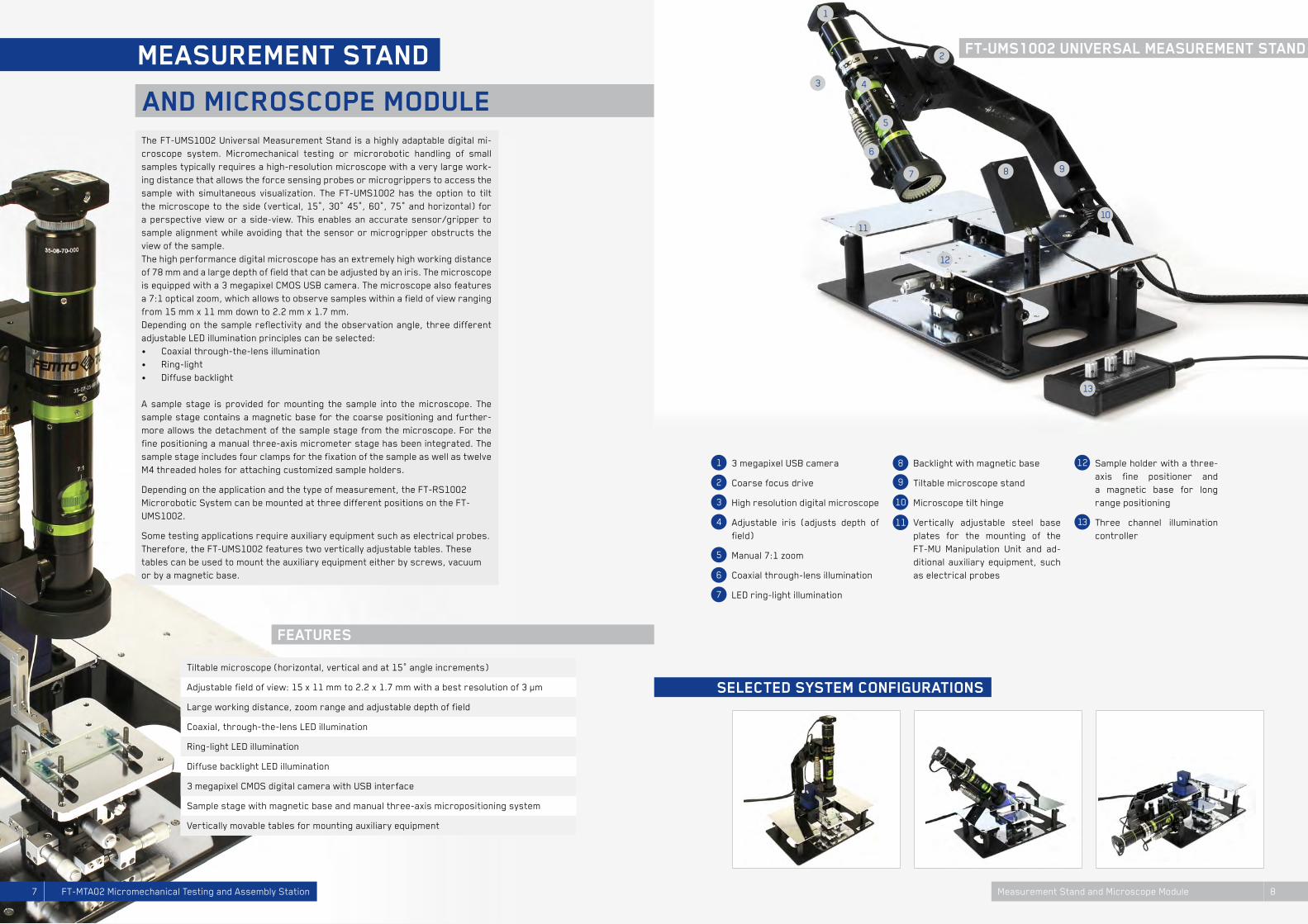
1283 megapixel USB camera
Coarse focus drive
High resolution digital microscope
Adjustable iris (adjusts depth of field)
Manual 7:1 zoom
Coaxial through-lens illumination
LED ring-light illumination
Backlight with magnetic base
Tiltable microscope stand
Microscope tilt hinge
Vertically adjustable steel base plates for the mounting of the FT-MU Manipulation Unit and ad-ditional auxiliary equipment, such as electrical probes
Sample holder with a three-axis fine positioner and a magnetic base for long range positioning
Three channel illumination controller
And miCrosCope module
meAsurement stAnd
The FT-UMS1002 Universal Measurement Stand is a highly adaptable digital mi-croscope system. Micromechanical testing or microrobotic handling of small samples typically requires a high-resolution microscope with a very large work-ing distance that allows the force sensing probes or microgrippers to access the sample with simultaneous visualization. The FT-UMS1002 has the option to tilt the microscope to the side (vertical, 15°, 30° 45°, 60°, 75° and horizontal) for a perspective view or a side-view. This enables an accurate sensor/gripper to sample alignment while avoiding that the sensor or microgripper obstructs the view of the sample.The high performance digital microscope has an extremely high working distance of 78 mm and a large depth of field that can be adjusted by an iris. The microscope is equipped with a 3 megapixel CMOS USB camera. The microscope also features a 7:1 optical zoom, which allows to observe samples within a field of view ranging from 15 mm x 11 mm down to 2.2 mm x 1.7 mm.Depending on the sample reflectivity and the observation angle, three different adjustable LED illumination principles can be selected:• Coaxial through-the-lens illumination• Ring-light• Diffuse backlight
A sample stage is provided for mounting the sample into the microscope. The sample stage contains a magnetic base for the coarse positioning and further-more allows the detachment of the sample stage from the microscope. For the fine positioning a manual three-axis micrometer stage has been integrated. The sample stage includes four clamps for the fixation of the sample as well as twelve M4 threaded holes for attaching customized sample holders.
Depending on the application and the type of measurement, the FT-RS1002 Microrobotic System can be mounted at three different positions on the FT-UMS1002.
Some testing applications require auxiliary equipment such as electrical probes. Therefore, the FT-UMS1002 features two vertically adjustable tables. These tables can be used to mount the auxiliary equipment either by screws, vacuum or by a magnetic base.
feAtures
seleCted system ConfigurAtions
1
1110
4
7
3
12
5
8
2
6
13
9
ft-ums1002 universAl meAsurement stAnd
Large working distance, zoom range and adjustable depth of field
Tiltable microscope (horizontal, vertical and at 15° angle increments)
Ring-light LED illumination
3 megapixel CMOS digital camera with USB interface
Vertically movable tables for mounting auxiliary equipment
Diffuse backlight LED illumination
Sample stage with magnetic base and manual three-axis micropositioning system
Coaxial, through-the-lens LED illumination
Adjustable field of view: 15 x 11 mm to 2.2 x 1.7 mm with a best resolution of 3 µm
7 8Measurement Stand and Microscope ModuleFT-MTA02 Micromechanical Testing and Assembly Station

4
1
2
3
The FT-WMS Modular Mechanical Testing Software enables the user-friendly development of customized micromechanical testing programs. This National Instruments’ LabVIEW based software library consists of predefined building blocks that can simply be assembled and reconfigured to develop custom micromechanical testing sequences. The simple drag-and-drop process of building blocks requires only a minimum of programming knowledge. While creating a new and customized testing sequence, the FT-WMS Modular Mechanical testing software automatically generates the elements for the graphical user interface such as controls and graphs. Furthermore, the mechanical testing software library can be combined with any other LabVIEW compatible software and hardware. An extensive documentation together with sample programs are provided to further simplify the development of your own testing sequence.
Graphical user interface of a custom micromechanical testing program
Selection of the graphical user interface controls of the FT-WMS Modular Mechanical Testing Software
Block diagram of a custom micromechanical testing program
Selection of the function library of the FT-WMS Modular Mechanical Testing Software
And hAndling softwAre suite
meChAniCAl testing
The FT-WFS Micromechanical Testing Software Suite has been developed to perform automated force-position-time measurements for the testing of me-chanical properties such as:• Stiffness• Elastic and plastic deformation• Linearity• Hysteresis• Breaking strength• Dimension/topography• Deflection range• Adhesion force• Actuation force
The user-friendly graphical user interface (GUI) features an automated con-tact detection mode that enables a fast and safe approach of the sensor to the sample. The software enables the measurement visualization (e.g. force vs. displacement or force vs. time data), recording and data exporting (.txt or .xls).The microscope camera image of the FT-UMS1002 Universal Measurement Stand can also be displayed in the software.The FT-WFS Micromechanical Testing Software Suite enables to automatically repeat measurements at one single position or at multiple positions on the sample. This function is used for cyclic testing or for array measurements in the area of interest. Typical applications for array measurements are the creation of topography maps or stiffness maps.
The FT-WGS Microhandling Software enables the user to perform sophisti-cated pick-and-place operations and microassembly tasks in an intuitive way, using a graphical user interface (GUI). The most important software features are:• High-precision positioning of the microgripper• Closed-loop gripping force control• Gripper force feedback, measurement data visualization and exporting
(.txt or .xls)• Software limit switches to define a safe working area and prevent crash-
ing the gripper• Position save and return function for repetitive handling and assembly
tasks
feAtures
1
43
2
Automated contact detection allows a safe sensor to sample approach
User-friendly graphical user interfaces (GUIs) for MS Windows
Automated, low-frequency cyclic testing
Software library for customized testing principles and sequences
Automated line- and array-measurements
Documentation and tutorials to aide creating customized testing principles and sequences
Automated compression / tensile testing, adhesion testing, deflection testing
Visualization, recording and exporting of measurement data
ft-wms modulAr meChAniCAl testing softwAre
ft-wfs miCromeChAniCAl testing softwAre
ft-wgs miCrohAndling softwAre
The FT-W1002 Mechanical Testing and Handling Software Suite is provided together with the FT-RS1002. The software suite consists of three parts:• FT-WFS Micromechanical Testing Software• FT-WGS Microhandling Software• FT-WMS Modular Mechanical Testing SoftwareThe FT-WFS and the FT-WGS are graphical user interfaces (GUIs) for MS Windows, which enable user-friendly plug-and-play type micromechanical testing and microassembly. The FT-WMS is a library based on National Instruments’ LabVIEW for the creation of cus-tomized micromechanical testing programs.
9 10Micromechanical Testing and Handling Software SuiteFT-MTA02 Micromechanical Testing and Assembly Station

AppliCAtion exAmples
miCrosystem testing
0 2 4 6
0
200
400
600
800
1000
App
lied
forc
e (µ
N)
Sample deflection (µm)
out-of-planestiffness (N/m)
in-planestiffness (N/m)
200
240
280
Sti
ffne
ss (
N/m
)
functionality criteria
chip map
0 2 4 6
0
200
400
600
800
1000
App
lied
forc
e (µ
N)
Sample deflection (µm)
out-of-planestiffness (N/m)
in-planestiffness (N/m)
200
240
280
Sti
ffne
ss (
N/m
)
functionality criteria
chip map
During the micro-manufacturing pro-cess development, a large number of process parameters influence the mechanical properties of the MEMS structures. In this application both the in-pane stiffness and out-of-plane stiffness of an array of MEMS flexures are tested using the FT-MTA02. By de-fining an upper and a lower limit for the target stiffness, a chip map is cre-ated to identify the working flexures (green) and flexures that are outside the desired specifications (red). Flex-ures that have not been successfully released from the wafer (very high stiffness) or flexures with cracks (low stiffness) are identified. The yield rate can easily be detected by the ratio of green and red marks.
A MEMS piezoelectric membrane is tested by characterizing its compli-ance as well as its topography while it is actuated. To obtain a high resolu-tion spatial representation, the “ar-ray measurement” capability of the FT-WFS Micromechanical Testing Soft-ware is used. Force-displacement data is automatically acquired at multiple positions in a 600 µm x 600 µm area. The top image illustrates the compli-ance (inverse of stiffness) of the mem-brane and the middle image illustrates the topography of the membrane at an actuation voltage of 0 V. Then, a volt-age potential of 150 V is applied to the membrane by two electric probes that are mounted on the steel base plates of the Universal Measurement Stand. The lower image illustrates the actu-ated membrane topography at 150 V.
An array of nanocantilevers for bio-logical screening applications has been fabricated featuring variable surface coatings at the nanocantilever tip. The FT-MTA02 system is used to measure both the elasticity of the nanocantile-ver and the adhesion force at the tip. The adhesion force corresponds to the negative “pulling” force during the un-loading of the nanocantilever.
Polymer materials (e.g. PMMA, PDMS, SU-8) are commonly used for MEMS sensors and actuators. However, the incorporation of polymers for mechan-ical purposes in MEMS devices raises new issues and challenges. In this ap-plication PMMA cantilevers are loaded to measure device properties such as buckling forces, elastic/plastic defor-mations and hysteresis.
defleCtion rAnge And stiffness meAsurements on A mems mirror
topogrAphy And CompliAnCe mApping of A piezoeleCtriC miCro-membrAne
testing of miCrofAbriCAtion yield
nAnoCAntilever Adhesion forCe testing
miCrosCAle testing of the mAteriAl properties of polymers
By definition, MEMS contain a mechanical structure. For most MEMS devices, the me-chanical properties of these structures are of great importance such that these sys-tems work optimally. Frequently tested mechanical parameters include stiffness, Young’s modulus, linearity, adhesion force, hysteresis, deflection, actuator force, yield strength, creep and topography. By the quantitative measurement of the mechanics at the micro-scale, the MEMS development time and cost can be reduced, as faulty devices can be identified at an early stage and the quality of the manufacturing process can be tested.
miCrosystem testing
0 20 40 60 80 100 120 140 160−20
0
20
40
60
80
100
0 2 4 6 8 10 120
1020304050607080
Rotation angle (°)
Tors
iona
l mom
ent
(nN
m)
0 2 4 6 8 10 12
05
1015202530
0
10
20
30
40
5035
App
lied
forc
e (µ
N)
Sample deflection (µm)
0 5 10 15 20 25 30 35 40-2
0
2
4
6
8
10
Rot
atio
n an
gle
(°)
Actuation voltage (V)
measurementlocations
reflection
FT-S Microforce Sensing Probe
Time (s)
Act
uati
on f
orce
(µN
)
Act
uati
on v
olta
ge (
V)
0
2
4
Z P
osit
ion
(µm
)
topography map atactuation voltage = 0 V 100 nm thick
Al pad
−2000
200
−2000
200
0
5
10
X Position (µm)Y Position (µm)
−2000
200
−2000
200X Position (µm)Y Position (µm)
0
2
4
Z P
osit
ion
(µm
)
−2000
200
−2000
200X Position (µm)Y Position (µm)
Com
plia
nce
(mm
/N) stiffness map at
actuation voltage = 0 V
topography map atactuation voltage = 150 V
V
0 20 40 60 80 100 120 140 160−20
0
20
40
60
80
100
0 2 4 6 8 10 120
1020304050607080
Rotation angle (°)
Tors
iona
l mom
ent
(nN
m)
0 2 4 6 8 10 12
05
1015202530
0
10
20
30
40
5035
App
lied
forc
e (µ
N)
Sample deflection (µm)
0 5 10 15 20 25 30 35 40-2
0
2
4
6
8
10
Rot
atio
n an
gle
(°)
Actuation voltage (V)
measurementlocations
reflection
FT-S Microforce Sensing Probe
Time (s)
Act
uati
on f
orce
(µN
)
Act
uati
on v
olta
ge (
V)
This application illustrates the me-chanical testing of a micromirror de-signed for large rotation angles. The reflective mirror plate is suspended by an elastic torsional beam, allowing the plate to rotate. The FT-MTA02 is used to perform compression tests at dif-ferent locations on the plate. From the measured force-deflection data both the maximum deflection range and the torsional stiffness of the mirror plate is extracted.
0 1 2 3 4−10.500.511.522.533.5
App
lied
forc
e (µ
N)
Sample deflection (µm)
adhesion force (µN)
0 20 40 60 80 100 120 140 160−20
0
20
40
60
80
100
0 2 4 6 8 10 120
1020304050607080
Rotation angle (°)
Tors
iona
l mom
ent
(nN
m)
0 2 4 6 8 10 12
05
1015202530
0
10
20
30
40
5035
App
lied
forc
e (µ
N)
Sample deflection (µm)
0 5 10 15 20 25 30 35 40-2
0
2
4
6
8
10
Rot
atio
n an
gle
(°)
Actuation voltage (V)
measurementlocations
reflection
FT-S Microforce Sensing Probe
Time (s)
Act
uati
on f
orce
(µN
)
Act
uati
on v
olta
ge (
V)
0
2
4
Z P
osit
ion
(µm
)
topography map atactuation voltage = 0 V 100 nm thick
Al pad
−2000
200
−2000
200
0
5
10
X Position (µm)Y Position (µm)
−2000
200
−2000
200X Position (µm)Y Position (µm)
0
2
4
Z P
osit
ion
(µm
)
−2000
200
−2000
200X Position (µm)Y Position (µm)
Com
plia
nce
(mm
/N) stiffness map at
actuation voltage = 0 V
topography map atactuation voltage = 150 V
V
0
2
4
Z P
osit
ion
(µm
)
topography map atactuation voltage = 0 V 100 nm thick
Al pad
−2000
200
−2000
200
0
5
10
X Position (µm)Y Position (µm)
−2000
200
−2000
200X Position (µm)Y Position (µm)
0
2
4
Z P
osit
ion
(µm
)
−2000
200
−2000
200X Position (µm)Y Position (µm)
Com
plia
nce
(mm
/N) stiffness map at
actuation voltage = 0 V
topography map atactuation voltage = 150 V
V
0 20 40 60 80 100 120 140 160−20
0
20
40
60
80
100
0 2 4 6 8 10 120
1020304050607080
Rotation angle (°)
Tors
iona
l mom
ent
(nN
m)
0 2 4 6 8 10 12
05
1015202530
0
10
20
30
40
5035
App
lied
forc
e (µ
N)
Sample deflection (µm)
0 5 10 15 20 25 30 35 40-2
0
2
4
6
8
10
Rot
atio
n an
gle
(°)
Actuation voltage (V)
measurementlocations
reflection
FT-S Microforce Sensing Probe
Time (s)
Act
uati
on f
orce
(µN
)
Act
uati
on v
olta
ge (
V)
0 50 100 150 200 250 300 3500
50
100
150
200
250
hysteresis
App
lied
forc
e (µ
N)
Sample deflection (µm)
11 12Microsystem Testing Applications FT-MTA02 Micromechanical Testing and Assembly Station

AppliCAtion exAmples
miCro-mAteriAl sCienCe
App
lied
forc
e (m
N)
Sample deflection (µm) 5 10 15 20 25 30 35 40 45 50
00
2
4
6
8
10
0 20 40 60 80 100 1200.6
0.7
0.8
0.9
1.0
1.1
1.2
Relaxation time (s)
App
lied
forc
e (m
N)
1000 2000 3000 40000.25
0.5
0.75
1.0
Number of cycles
Fibe
r el
onga
tion
(%
)
600
650
700
750
Sti
ffne
ss (
N/m
)
Silica microfibers created by roller electrospinning are mechanically test-ed by performing tensile tests. Both the sample preparation process and the tensile testing are performed us-ing the FT-MTA02 Micromechanical Testing and Assembly Station. First, an individual fiber is collected using a FT-G102 Force Sensing Micro-gripper and attached on one side onto a glass slide using UV curable glue. Subsequently, the opposite side of the fiber is glued to the probe tip of a FT-S10’000 Microforce Sensing Probe. The upper microscope image shows the fiber in a relaxed state. The fiber is stretched until it is straight and then stretched even further. The stiffness, the elongation, the maximum yield strength and the maximum elongation are measured. Additionally, the relaxa-tion behavior is analyzed by stretch-ing the fiber and measuring the force while keeping the position constant. Cyclic testing is performed to measure the change of stiffness and fiber elon-gation after a large number of loading and unloading cycles.
For the manufacturing of implantable neural electrodes, a highly compliant platinum microsphere filled PDMS com-posite material has been developed. Bending tests are performed on the 300 µm diameter electrode to measure the elastic and plastic deformation at different strain levels.
eleCtroACtive polymer ACtuAtor testing
nAnoCrystAlline diAmond membrAne testing
miCrosCAle testing of porous mAteriAls
miCrosCAle tensile testing of siliCA fibers
pt-siliCone Composite miCroeleCtrode testing
The development of smart materials opens up promising applications and products, especially in the field of mi-crosensors and microactuators. Quantitative microscale and nanoscale material testing is crucial for the design of new high-tech materials and material compounds.
miCro-mAteriAl sCienCe
0 1 2 3 4 5
−1
0
1
2
3
4
Act
uato
r fo
rce
(µN
) /
appl
ied
volt
age
(V)
Time (s)
0 0.5 1 1.5 20
50
100
150
200
Can
tile
ver
defle
ctio
n (µ
m)
Applied voltage (V)
response time (s)
actuation force (uN)
actuation range (µm)
clamping electrodes
EAP microactuator
sensor probe tip
Conjugated or conducting polymers are receiving significant attention as smart materials for novel microfabri-cated devices such as actuators and sensors. The deflection range, the ac-tuation force and the time-response of the beam-shaped electroactive poly-mer (EAP) actuator are tested in this application. The beam-shaped microactuators are clamped between two electrodes, ena-bling the application of the actuation signal to drive the microactuator. The top graph illustrates the maximum de-flection of the EAP actuator beam tip versus the actuation voltage. The low-er graph shows the driving force gen-erated by the EAP actuator as well as the square-wave driving signal plotted versus time.
This work reports the testing of a na-nocrystalline diamond and aluminum nitride membrane for the use in tun-able micro-optics. Both the topography and the stiffness of the membrane are tested at a large number of positions to create images with a high spatial reso-lution, so-called “topography maps” and “stiffness maps”. The upper right graph illustrates the topography of the micromembrane, while the lower right graph shows its stiffness distribution. The lower left graph is a cross-section of the stiffness map going through the central section of the membrane.
App
lied
forc
e (µ
N)
Sample deflection (µm) 0 50 150 200 250 300 350
0
4
8
12
16
-4
0 1 2 3 4 5
−1
0
1
2
3
4
Act
uato
r fo
rce
(µN
) /
appl
ied
volt
age
(V)
Time (s)
0 0.5 1 1.5 20
50
100
150
200
Can
tile
ver
defle
ctio
n (µ
m)
Applied voltage (V)
response time (s)
actuation force (uN)
actuation range (µm)
clamping electrodes
EAP microactuator
sensor probe tip
100 200 300 400 500 600
0
100
200
300
Position (µm)
Sti
ffne
ss (
N/m
)
Log 10
(Sti
ffne
ss (
N/m
))
0 200 400 600 0
200
400
600
024
X P
osit
ion
(µm
)
Y Position (µm)
0 200 400 600
0
200
400
600
0
2
X P
osit
ion
(µm
)
Y Position (µm)
Z P
osit
ion
(µm
)
100 200 300 400 500 600
0
100
200
300
Position (µm)
Sti
ffne
ss (
N/m
)
Log 10
(Sti
ffne
ss (
N/m
))
0 200 400 600 0
200
400
600
024
X P
osit
ion
(µm
)
Y Position (µm)
0 200 400 600
0
200
400
600
0
2
X P
osit
ion
(µm
)
Y Position (µm)
Z P
osit
ion
(µm
)
100 200 300 400 500 600
0
100
200
300
Position (µm)
Sti
ffne
ss (
N/m
)
Log 10
(Sti
ffne
ss (
N/m
))
0 200 400 600 0
200
400
600
024
X Po
siti
on (
µm)
Y Position (µm)
0 200 400 600
0
200
400
600
0
2
X Po
siti
on (
µm)
Y Position (µm)
Z Po
siti
on (
µm)
0 1 2 3 4 5
−1
0
1
2
3
4
Act
uato
r fo
rce
(µN
) /
appl
ied
volt
age
(V)
Time (s)
0 0.5 1 1.5 20
50
100
150
200
Can
tile
ver
defle
ctio
n (µ
m)
Applied voltage (V)
response time (s)
actuation force (uN)
actuation range (µm)
clamping electrodes
EAP microactuator
sensor probe tip
100 200 300 4000
100
200
300
400
App
lied
forc
e (µ
N)
Sample deflection (µm)
Porous and cellular materials such as polymer foams, metal foams or certain biomaterials (e.g. trabecular bone) feature a complex material behavior. Force-displacement measurements are performed to validate complex fi-nite element models (FEM) that have been developed for these materials. Sample sizes from a few micrometers up to several millimeters are tested.
13 14Micro-Material Science ApplicationsFT-MTA02 Micromechanical Testing and Assembly Station

AppliCAtion exAmples
miCrohAndling
Str
ess
(MPa
)
Fiber strain (%)0 100 200 300 400 500 600 700
0
2
4
6
8
10
The measurement of the mechanical properties of proteins can give insights into their functionalities. The tensile testing of single Fibronectin fibers demonstrates that its Young’s modulus greatly increases, as it is extended. Through repeated testing, evidence is given for the mechanical, repeatable unfolding of their force-bearing back-bone hydrogen bonds.
Biological research often deals with micrometer-sized samples such as small tissues or individual cells. The handling of these objects is performed with FT-G Force Sensing Microgrip-pers featuring high resolution force feedback to avoid damaging the sensi-tive samples. The force-feedback also allows measuring the object size and its mechanical properties.
The measurement of the mechanical properties of the Zona Pellucida (bi-omembranes) of fertilized and non-fer-tilized cells is demonstrated on mouse oocytes and embryos. The results pro-vide evidence for protein cross-linking that biologists have proposed as the mechanism by which zona pellucida hardening occurs.
The fruit fly possesses a flight control system for stable flight. In this applica-tion quantitative reverse-engineering was used to study lift control in fruit flies. The fly is mounted on the Micro-force Sensing Probe of the FT-MTA02. Then, high bandwidth lift force data is acquired to resolve the force propaga-tion during the individual wing beat cy-cles of the fly.
Insect wings are ultra-lightweight me-chanical structures, strengthened by a number of longitudinal veins, which have cross-connections that form closed “cells” in the membrane. For analyzing the mechanics of a butterfly wing, an automated array measure-ment was performed. The figure shows the stiffness map of the insect wing.
3d miCropArt Assembly
in-liquid Cell hAndling
sAmple prepArAtion
tensile testing of protein fibers
meChAniCAl ChArACterizAtion of Cell membrAnes
drosophilA lift forCe meAsurements
struCturAl AnAlysis of inseCt wings
Since the mechanical properties of biological samples are often tightly coupled to their physiological functions, a new field has emerged, called Mechanobiology. Forces influ-ence biological systems on the level of organisms, tissues and cells. Multi-scale mechani-cal testing therefore plays an important role in the field of Mechanobiology for the under-standing of the relationship between mechanics and biological processes.
meChAno-biology
Standard microfabrication processes are limited to a planar fabrication and do not allow the creation of complex three-dimensional structures. Addi-tionally, only certain combinations of different materials are possible, limit-ing the functionality of such microfab-ricated devices and systems. For the development of true three-dimensional hybrid micro-electromechanical sys-tems microassembly is required. For a biomedical application, the FT-G Microgripper was used to assemble soft-magnetic electroplated nickel pieces into a three dimensional struc-ture. Subsequently, the assembled parts are combined with a silicon-based microsensor.
The analysis of microscopic samples often requires challenging sample preparation steps due to the small sample size of the objectives under in-vestigation. By equipping the FT-MTA02 with FT-G series microgrippers, mi-croscopic objects can be handled.The image sequence illustrates the sample preparation of a microfiber for micromechanical testing. First, a single fiber is extracted from a larger fiber bundle. Then, the fiber is dipped into a droplet of UV curable glue on one end and subsequently attached to the border of a glass slide. This method al-lows for the attachment of the Micro-force Sensing Probe on the other side of the sample for tensile testing.
App
lied
forc
e (µ
N)
Sample deflection (µm) 0 10 20 30 40 50 60 70
0
2
4
6
8
puncture force
App
lied
forc
e (µ
N)
Time (ms) 0 2 4 6 8 10 12 14 16 18
-20
-10
0
10
20
30
0044
8812
12 16200
2
X Position (mm)Y Position (mm)
Log 10
sti�
ness
(N/m
)
0 0.20.40.60.81 1.21.41.61.82
x 104
−16000−14000−12000−10000−8000−6000−4000−20000−100001000
X Position [um]Y Position [um]
Z Po
sitio
n [u
m] Z Position [um]
−800−600−400−2000200400600800
1
3 4
2
15 16Mechano-Biology and Micro handling ApplicationsFT-MTA02 Micromechanical Testing and Assembly Station

ACCessories
ft-g forCe sensing miCrogripper
ft-b modulAr system bAses And miCrosCope AdApters
17 18AccessoriesFT-MTA02 Micromechanical Testing and Assembly Station
The FemtoTools FT-S Microforce Sens-ing Probes are microforce sensors capable of measuring forces from mil-linewtons (10-3 N) down to several na-nonewtons (10-9 N) along the sensor’s probe axis. Both compression and ten-sion forces can be measured. The FT-S Microforce Sensing Probes are avail-able with two different tip options. Ei-ther a flat silicon tip with a tip size of 50 µm by 50 µm or a sharp tungsten probe tip with a tip radius smaller than 2 µm is offered.The individual calibration in combina-tion with an outstanding long-term sta-bility guarantees significantly higher measurement accuracy than any oth-er force sensing system in this force range. A calibration data sheet is deliv-ered for each individual sensor.
The FT-G Microgripper series is de-signed to handle micro- to nanometer-sized objects. The initial openings of the gripper arms are 30 µm, 60 µm and 100 µm. The opening can be con-trolled with nanometer precision, such that the gripper arms are fully closed upon applying the maximum actuation voltage.Both the FT-G32 and the FT-G102 Force Sensing Microgripper feature an integrated force sensor to meas-ure the gripping force. Force feedback greatly enhances the efficiency and reliability of automated microhandling systems and assembly processes.
For a user-friendly integration of the FT-RS1002 Microrobotic System into a large range of microscopes, manipula-tor bases as well as custom-fabricated microscope adapters are available.
ft-mb magnetic baseThe FT-MB Magnetic Base (upper im-age) is designed to fix the manipulation unit to any ferromagnetic work sur-face such as steel. The magnetic base features an on/off switch for attach-ment and detachment.
ft-A microscope AdapterIn case the system cannot be directly integrated into your microscope us-ing the included screw-on-base or the above described magnetic base, special adapter plates (lower image) can be provided by FemtoTools upon request.
The FemtoTools FT-S1000-LAT Lateral Microforce Sensing Probe is a micro-force sensor capable of measuring forces from one millinewton (10-3 N) down to several nanonewtons (10-9 N) perpendicular to the sensor’s axis. Both compression and tension forces can be measured. This off-axis meas-uring capability allows for the vertical micromechanical testing while observ-ing both the sensing-probe tip and the sample under a top-view microscope.
ft-s miCroforCe sensing probes
ft-s-lAt lAterAl miCroforCe sensing probe
FT-S100 +/- 100 µN 5 nN
FT-S100-TP
FT-G32 0 - 30 µm yes
FT-S1’000-LAT +/- 1’000 µN 50 nN
FT-S10’000 +/- 10’000 µN 500 nN
FT-S10’000-TP
FT-G102 0 - 102 µm yes
FT-S100’000 +/- 100’000 µN 5’000 nN
FT-S1’000 +/- 1’000 µN 50 nN
FT-S1’000-TP
FT-G62 0 - 60 µm no
Model Range Resolution
Microforce sensing probe with tungsten tip option
Model Opening Force Sensor
Model Range Resolution
sensor probe length: 3 mmsensor probe thickness: 50 µm
12
5 µ
m
50 µm
300 µm
45°
sensitive direction
Standard sensing probe tip geometry
Tungsten tip sensing probe geometry
tungsten probetip radius ≤ 2 µm
2.5 +/- 0.5 mm
sensor probe length: 3 mmsensor probe thickness: 50 µm
50 µm
10 µ
m
45°
sensitive direction
Sensing probe tip geometry
sensor probe length: 3 mmsensor probe thickness: 50 µm
12
5 µ
m
50 µm
300 µm
45°
sensitive direction
Standard sensing probe tip geometry
Tungsten tip sensing probe geometry
tungsten probetip radius ≤ 2 µm
2.5 +/- 0.5 mm

ft-rs1002 miCrorobotiC system
Number of axes 3
Key functionality Force acquisition Control of the manipulation unit Position readout Control of the microgripper Data synchronization
Actuation principle (fine) Piezoelectric scanning
Interface USB
Min. motion increm. (fine) 1 nm
Maximum force range*1) ± 100 mN
Actuation range (coarse) 26 mm x 26 mm x 26 mm
General purpose I/O 2 x ±10 V analog inputs 1 x 0-5 V analog output (≤5mA) 4 x digital input/output 1 x digital counter/trigger
Encoder resolution 1 nm
Encoder resolution 1 nm
*1) Using a FT-S100’000 Microforce Sensing Probe *2) Using a FT-S100 Microforce Sensing Probe
Min. motion increm. (coarse) 50 nm
Joystick control Hardware joysticks Software joysticks Computer keyboard
Actuation range (fine) 1.5 µm x 1.5 µm x 1.5 µm
Power supply 12 V power supply with Europlug (110 V/230 V)
Max. measurement range 26 mm (vertical, horizontal, angle)
Tool adapter mounts 4 linear adapter 6 angular adapters 1 sensor / gripper head
Actuation principle (coarse) Piezoelectric stepping
Sensor protection mode Axial sensor protection Automated sample approach
Maximum velocity 5 mm/s
Smallest force resolution*2) 5 nN
ft-mu manipulation unit
ft-msC modular system Controller
ft-ums1002 digitAl miCrosCope stAnd
Optical zoom range 1:7
Horizontal coarse positioning 110 mm x 110 mm range (magnetic base)
Working distance 78 mm
Camera 3 megapixel CMOS sensor
Field of view, zoomed in 2.2 mm x 1.7 mm
Vertical fine positioning 10 mm range (fine focus)
Microscope tilting angle 0° (vertical), 15°, 30°, 45°, 60°, 75°, 90° (horizontal)
Optical resolution, zoomed in 3 µm
Iris adjustable
Field of view, zoomed out 15 mm x 11 mm
Horizontal fine positioning 12.5 mm x 12.5 mm range
Focus block range (coarse) 55 mm
Interface USB
microscope
sample stage
Coaxial through-lens LED, adjustabe
Backlight LED, adjustabe
Sample mounting 4 clamps (12 x M4 threads)
Ring light LED, adjustabe
Power supply 12 V power supply with Europlug (110 V / 230 V)
lighting
teChniCAl
speCifiCAtions
19 20FT-MTA02 Micromechanical Testing and Assembly Station
83 mm
83 mm
99
mm
10
3 m
m
145 mm
500
mm
350 mm
500
mm
430 mm615 mm
Technical Specifications

teChniCAl
ft-s miCroforCe sensing probes / ft-g miCrogrippers
ft-rs1002 miCrorobotiC system
ft-en1002 enClosure
Acrylic glass enclosure to prevent air flow
FT-WFS Micromechanical Automated compression Testing Software and tensile testing
Two cable feed-trough openings
FT-WMS Modular Enables user-friendly Mechanical Testing development of customized Software micromechanical testing programs.
Protection against mechanical damage, dust and airflow
Compatible with desktop vibration isolation
FT-WGS Microhandling Allows the control of the Software microhandling and assembly procedure.
enclosure
ft-w1002 mechanical testing and handling software
Type Range Resolution (at 10 Hz)
Type Opening Force Sensor
FT-S1’000 /-LAT ± 1’000 µN 50 nN
FT-G62 0 - 60 µm no
FT-S100’000 ± 100’000 µN 5’000 nN
FT-S100 ± 100 µN 5 nN
FT-G32 0 - 30 µm yes
FT-S10’000 ± 10’000 µN 500 nN
FT-G102 0 - 100 µm yes
ft-s microforce sensing probe (sold separately)
ft-g microgripper (sold separately)
speCifiCAtions
21 22Technical SpecificationsFT-MTA02 Micromechanical Testing and Assembly Station
805
mm
805
mm
920 mm 625 mm
sensor probe length: 3 mmsensor probe thickness: 50 µm
12
5 µ
m
50 µm
300 µm
45°
sensitive direction
Standard sensing probe tip geometry
Tungsten tip sensing probe geometry
tungsten probetip radius ≤ 2 µm
2.5 +/- 0.5 mm

FemtoTools AGFurtbachstrasse 48107 Buchs / ZHSwitzerland
T +41 44 844 44 25F +41 44 844 44 27
www.femtotools.com
FEMTO TOOLS