World of Automation - Hiquel · Ue/Ie DC-13 expected life time ... DIP-Switch: autom.-Reset / Relay...
35
Chapter 2: Monitoring relays World of Automation www.hiquel.com
Transcript of World of Automation - Hiquel · Ue/Ie DC-13 expected life time ... DIP-Switch: autom.-Reset / Relay...
Chapter 2: Monitoring relays
World of Automation
www.hiquel.com

Index
2:00
22Chapter 2: Monitoring relays
HIGH QUALITY ELECTRONICS
2009HIQUEL X01.00
TCC-H2
TCC-W
TCC-H
ICC
INFO In-case series
TCC-GW
ICV
TCV-H
TCV-W
TCV-P
TCP-M
TCP-V / PCP-V
.05.05
.04.04
.03.03
.02.02
.01.01
.06.06
.07.07
.08.08
.09.09
.10.10
.15.15
.16.16
.17.17
INDEXINDEX
.11.11
.12.12
.13.13
module overview
ICP
TCP
.14.14 TCP-SF
ICPV
TCP-LC / TCP-LS.18.18
TCP-3N.19.19
ICL.20.20
TCL.21.21
TCL-LC.22.22
TCL-3.23.23
TET.24.24
TCV-SK.25.25
ICM.26.26
TCM.27.27
TCM-LC.28.28
TCS.29.29
DGR.30.30
TCE.31.31
DELR.32.32
TPS / UPS.33.33
2:01
in-case Seriesin-case Series
HIGH QUALITY ELECTRONICS
2009HIQUELX01.00
in-c
ase
Seri
es
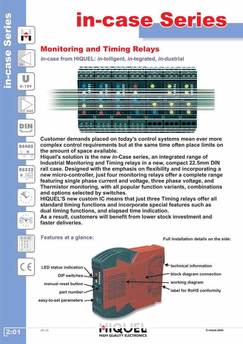
Customer demands placed on today's control systems mean ever morecomplex control requirements but at the same time often place limits onthe amount of space available.Hiquel's solution is the new -Case series, an integrated range ofIndustrial Monitoring and Timing relays in a new, compact 22.5mm DINrail case. Designed with the emphasis on flexibility and incorporating anew micro-controller, just four monitoring relays offer a complete rangefeaturing single phase current and voltage, three phase voltage, andThermistor monitoring, with all popular function variants, combinationsand options selected by switches.HIQUEL'S new custom IC means that just three Timing relays offer allstandard timing functions and incorporate special features such asdual timing functions, and elapsed time indication.As a result, customers will benefit from lower stock investment andfaster deliveries.
in
in in in in-case from HIQUEL: -telligent, -tegrated, -dustrial
Monitoring and Timing RelaysMonitoring and Timing Relays
Features at a glance:
technical information
block diagram connection
working diagram
label for RoHS conformity
Full installation details on the side:
LED status indication
DIP switches
manual reset button
part number
easy-to-set parameters
in
out
DIN
RS485
RS232
RTC
U0-10V
189 9=*
7
4
1
0
8
5
2
.
9
6
3
=
/
*-
+
2:02
overview
ICCICC
HIGH QUALITY ELECTRONICS
2009HIQUELX01.00
specification
ordering information
sin
gle
phase
curre
nt
contr
ol
supply voltage variation
frequency range
duty cycle
repeat accuracy
output relay specification
Ue/Ie AC-15
Ue/Ie DC-13
expected life time
operating conditions
nominal voltage -20%..+10%
48 - 63 Hz
100%
<1%
max. 6A 230V~
24V/1,5A 115V/1,5A 230V/1,5A
24V/1A
-20 to 60 °C non condensing°C
10 x 106
operations
8 x 10⁴
operations
mechanical
electrical
DPCO
Gehäusetypenpart no supply output
ICC 24Vac
ICC 115Vac
ICC 230Vac
DPCO
DPCO
DPCO
DPCOICC 400Vac
housing types
L
L
L
L
115V~
230V~
400V~
24V~ 2,5VA/1W
2,5VA/1W
2,5VA/1W
2,5VA/1W
yes
yesyes
yes
* The measurement is galvanically isolated from the power supplyinput
Control relay activeControl relay passive
Contact closedContact open
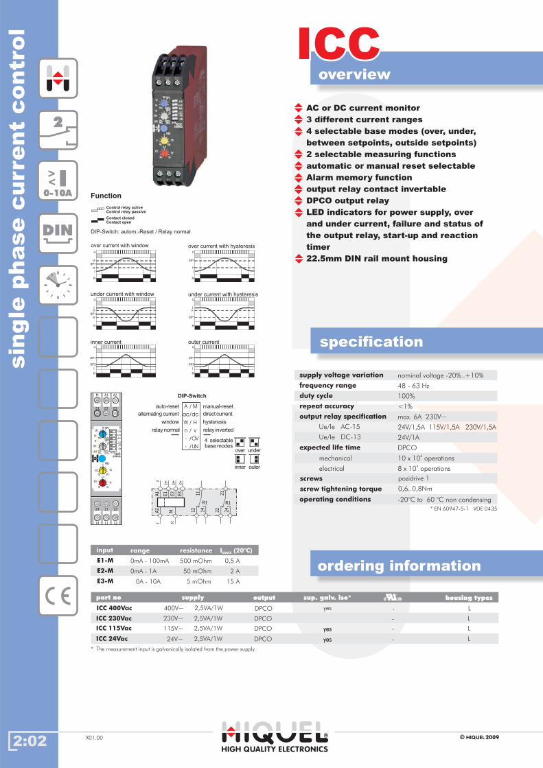
Function
2
DIN
I<
<
0-10A
DIP-Switch: autom.-Reset / Relay normal
over current with window over current with hysteresisU
SP1
I
W
R
W
U
SP1
H
R
I
U
SP1W
W
R
I
U
SP1
H
R
I
under current with window
inner current
under current with hysteresis
U
SP1
R
I
SP2
U
SP1
R
I
SP2
outer current
input
E2-M
E1-M
E3-M
range resistance I (20°C)EMAX
0mA - 1A 50 mOhm 2 A
0mA - 100mA 500 mOhm 0,5 A
0A - 10A 5 mOhm 15 A
4 selectablebasemodes
over under
inner outer
manual-reset
direct current
hysteresis
relay inverted
auto-reset
alternatingcurrent
window
relaynormal
DIP-Switch
/
/
/
/
/
/
M
H
dc
A
W
ac
v
OV
UN
n
-
-
sup. galv. iso*
-
-
-
-
AC or DC current monitor
3 different current ranges
4 selectable base modes (over, under,
between setpoints, outside setpoints)
2 selectable measuring functions
automatic or manual reset selectable
Alarm memory function
output relay contact invertable
DPCO output relay
LED indicators for power supply, over
and under current, failure and status of
the output relay, start-up and reaction
timer
22.5mm DIN rail mount housing
screws
screw tightening torque 0,6..0,8Nm
pozidrive 1
* EN 60947-5-1 VDE 0435
U
100%0%
50
F
R1
SP1
ts
tr
0V
UNICC
230Vac
10s0s
5
5s0s
2,5
100%0%
SP2H
0% 25%
ts
tr
IN/OU
A/M
ac/dc
-/UN
-/OV
W/H
n/v
MR
M A1 A2
E2 E3
24 21 22
14 11 12
E1
12
11 21
14
R1
E3
A1
E2
E1
22 24
R1
~ ~+
~+
~+
MA2
~~ -
yes
2:03
overview
TCC-HTCC-H
HIGH QUALITY ELECTRONICS
2009HIQUEL X01.00
specification
ordering information
over/u
nder
curre
nt
contro
l
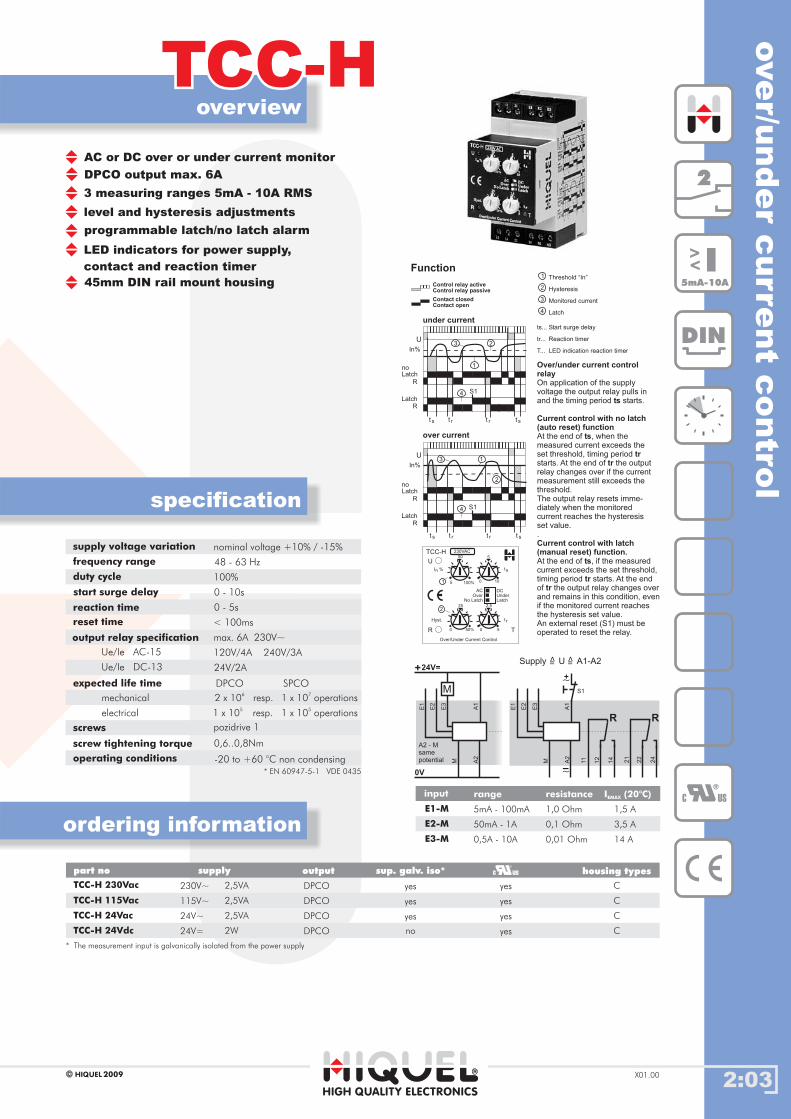
AC or DC over or under current monitor
DPCO output max. 6A
level and hysteresis adjustments
programmable latch/no latch alarm
LED indicators for power supply,
contact and reaction timer
45mm DIN rail mount housing
3 measuring ranges 5mA - 10A RMS
supply voltage variation
frequency range
duty cycle
start surge delay
reaction time
reset time
output relay specification
Ue/Ie AC-15
Ue/Ie DC-13
expected life time
operating conditions
nominal voltage +10% / -15%
48 - 63 Hz
100%
0 - 10s
0 - 5s
< 100ms
max. 6A 230V~
120V/4A 240V/3A
24V/2A
-20 to +60 °C non condensing
mechanical
DPCO SPCO
electrical
2 x 10⁶
resp. 1 x 10⁷
operations
1 x 10⁵
resp. 1 x 10⁵
operations
input
E2-M
E1-M
E3-M
range resistance I (20°C)EMAX
50mA - 1A 0,1 Ohm 3,5 A
5mA - 100mA 1,0 Ohm 1,5 A
0,5A - 10A 0,01 Ohm 14 A
A1
11 21
12 22
14 24
A2
M
E3
E2
E1
-~
Control relay activeControl relay passive
Contact closedContact open
Function
under current
over current
S1
U
In%
t s t st r t r
1
1
2
2
3
3
4
4
Threshold “In”
Hysteresis
Monitored current
Latch
Over/under current controlrelay
ts
Current control with no latch(auto reset) function
ts
trtr
Current control with latch(manual reset) function.
On application of the supplyvoltage the output relay pulls inand the timing period starts.
At the end of , when themeasured current exceeds theset threshold, timing periodstarts. At the end of the outputrelay changes over if the currentmeasurement still exceeds thethreshold.The output relay resets imme-diately when the monitoredcurrent reaches theset value..
hysteresis
At the end of , if the measuredcurrent exceeds the set threshold,timing period starts. At the endof the output relay changes overand remains in this condition, evenif the monitored current reachesthe hysteresis set value.An external reset (S1) must beoperated to reset the relay.
ts
trtr
S1
U
In%
LatchR
R
noLatch
t s t st r t r
1
23
4
ts...
tr...
T...
Start surge delay
Reaction timer
LED indication reaction timer
A1
A2
M
E3
E2
E1
+24V=
0V
R R
M
Supply U A1-A2=
>
=
>
LatchR
R
noLatch
A2 - Msamepotential
+~S1
1
2
230VAC
U
R T
TCC-H
Over/Under Current Control
5
50
100%
50%
25
0
0
0 5
2,5
5
10
AC
LatchUnder
No LatchOver
I %n ts
trHyst.
DC
Gehäusetypenpart no supply output
TCC-H 230Vac
TCC-H 115Vac
TCC-H 24Vac
115V~
24V~
24V=
230V~ DPCO
DPCO
DPCO
DPCOTCC-H 24Vdc
housing types
yes
yes
yes
yes
C
C
C
C
2,5VA
2,5VA
2,5VA
2W
sup. galv. iso*
yes
yes
yes
no
* The measurement is galvanically isolated from the power supplyinput
2
DIN
C US
I<
<
5mA-10A
screws
screw tightening torque 0,6..0,8Nm
pozidrive 1
* EN 60947-5-1 VDE 0435

2:04
overview
TCC-WTCC-W
HIGH QUALITY ELECTRONICS
2009HIQUELX01.00
specification
ordering information
curre
nt
monit
or
win
dow
functi
on
AC or DC over or under current monitor
with window function
DPCO output max. 6A
level and hysteresis adjustments
3 measuring ranges 5mA - 10A RMS
programmable latch/no latch alarm
LED indicators for power supply,
contact and reaction timer
45mm DIN rail mount housing
supply voltage variation
frequency range
duty cycle
start surge delay
reaction time
reset time
output relay specification
Ue / Ie AC-15
Ue / Ie DC-13
expected life time
operating conditions
nominal voltage +10% / -15%
48 - 63 Hz
100%
0 - 10s
0 - 5s
< 100ms
max. 6A 230V~
120V/4A 240V/3A
24V/2A
-20 to +60°C non condensing
mechanical
electrical
DPCO SPCO
2 x 10⁶
resp. 1 x 10⁷
operations
1 x 10⁵
resp. 1 x 10⁵
operations
Gehäusetypenpart no supply output
TCC-W 230Vac
TCC-W 115Vac
TCC-W 24Vac
115V~
24V~
24V=
230V~ DPCO
DPCO
DPCO
DPCOTCC-W 24Vdc
housing types
yes
yes
yes
yes
C
C
C
C
2,5VA
2,5VA
2,5VA
2W
sup. galv. iso*
yes
yes
yes
no
* The measurement is galvanically isolated from the power supplyinput
input
E2-M
E1-M
E3-M
range resistance I (20°C)EMAX
50mA - 1A 0,1 Ohm 3,5 A
5mA - 100mA 1,0 Ohm 1,5 A
0,5A - 10A 0,01 Ohm 14 A
S1
t s t st r t r
Latch
R
R
U
In%
N.C.
N.O.
4
1
3 2
Control relay activeControl relay passive
Contact closedContact open
Function1
2
3
4
Threshold “In”
Hysteresis
Monitored current
Latch
ts...
tr...
T...
Start surge delay
Reaction timer
LED indication reaction timer
On application of the supply voltagewith selected, the outputrelay pulls in and the timing periodstarts.
At the end of , if the measuredcurrent exceeds the window in eitherdirection, timing period starts. At theend of , if the measurement stillexceeds the setpoint the output relaychanges over.The output relay resets immediately,when the monitored current reachesthe hysteresis set value.
ts
ts
trtr
Current control with latch(manual reset) function
N.O. Mode
At the end of , when the measuredcurrent exceeds the window in eitherdirection, timing period starts.At the end of , if the measurementstill exceeds the setpoint the outputrelay changes over and remains in thiscondition, even when the measuredcurrent reaches the hysteresis setvalue.An external reset (S1) must be operatedto reset the relay.
Current control with no latch(auto reset) function
ts
trtr
230VAC
U
R T
TCC-W
Current Control
5
50
100%
50%
25
0
0
0 5
2,5
5
10
AC
LatchN.O.
No LatchN.C.
I %n t s
t rWindow
DC
1
2
A1
11 21
12 22
14 24
A2
M
E3
E2
E1
-~
A1
A2
M
E3
E2
E1
+24V=
0V
MSupply U A1-A2=
>
=
>
R R
A2 - Msamepotential
+~S1
C US
2
DIN
I<
<
5mA-10A
screws
screw tightening torque 0,6..0,8Nm
pozidrive 1
* EN 60947-5-1 VDE 0435
2:05
overview
TCC-H2TCC-H2
HIGH QUALITY ELECTRONICS
2009HIQUEL X01.00
specification
ordering information
over/u
nder
curre
nt
monito
rw
ithtw
osw
itch
poin
ts
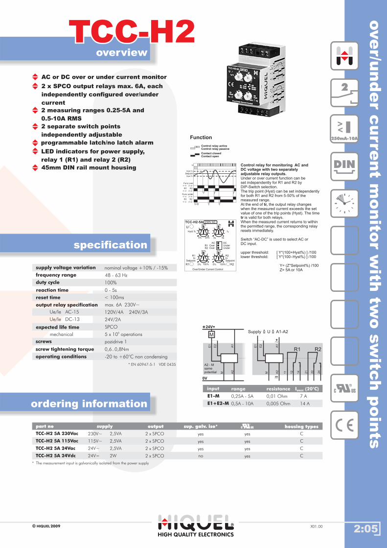
AC or DC over or under current monitor
2 x SPCO output relays max. 6A, each
independently configured over/under
current
2 measuring ranges 0.25-5A and
0.5-10A RMS
2 separate switch points
independently adjustable
programmable latch/no latch alarm
LED indicators for power supply,
relay 1 (R1) and relay 2 (R2)
45mm DIN rail mount housing
supply voltage variation
frequency range
duty cycle
reaction time
reset time
output relay specification
Ue/Ie AC-15
Ue/Ie DC-13
expected life time
operating conditions
nominal voltage +10% / -15%
48 - 63 Hz
100%
0 - 5s
< 100ms
max. 6A 230V~
120V/4A 240V/3A
24V/2A
-20 to +60°C non condensing
5 x 10⁶
operationsmechanical
SPCO
Gehäusetypenpart no supply output
TCC-H2 5A 230Vac
TCC-H2 5A 115Vac
TCC-H2 5A 24Vac
115V~
24V~
24V=
230V~ 2 x SPCO
2 x SPCO
2 x SPCO
2 x SPCOTCC-H2 5A 24Vdc
housing types
yes
yes
yes
yes
C
C
C
C
2,5VA
2,5VA
2,5VA
2W
sup. galv. iso*
yes
yes
yes
no
* The measurement is galvanically isolated from the power supplyinput
input
E1+E2-M
E1-M
range resistance I (20°C)EMAX
0,5A - 10A 0,005 Ohm 14 A
0,25A - 5A 0,01 Ohm 7 A
A1
11 21
12 22
14 24
+~
A2
M
E2
E1
-~
A1
A2
M
E2
E1
+24V=
0V
MSupply U A1-A2=
>
=
>
R1 R2
A2 - Msamepotential
230V AC
U
R1 R2
TCC-H2-5A
Over/Under Current Control
5%
25%
50%
100% 5%
0s
5% 100%
2,5s
5s
ACUnderUnder
R1 OverR2 Over
Hyst.% t r
R1In
Setpoint
R2InSetpoint
DC
50% 50%
Control relay activeControl relay passive
Contact closedContact open
Function
Control relay for monitoring AC andDC voltage with two separatelyadjustable relay outputs.
tr,
tr
Under or over current function can beset independently for R1 and R2 byDIP-Switch selection.The trip point (Hyst) can be set independentlyfor both R1 and R2 from 5-50% of themeasured range.At the end of the output relay changeswhen the measured current exceeds the setvalue of one of the trip points (Hyst). The time
is valid for both relays.When the measured current returns to withinthe permitted range, the corresponding relayresets immediately.
Switch “AC-DC” is used to select AC orDC input.
upper threshold: [ Y*(100+Hyst%) ] /100lower threshold: [ Y*(100-Hyst%) ] /100
Y= (Z*Setpoint%) /100Z= 5A or 10A
U
11-14 21-24
R1
SetpointHyst.%
Hyst.%
trt=
t
Func:over
11-12 21-22
R2
11-14 21-24
R1
Func:under
11-12 21-22
R2
t t
t t
2
DIN
C US
I<
<
250mA-10A
screws
screw tightening torque 0,6..0,8Nm
pozidrive 1
* EN 60947-5-1 VDE 0435
2:06
overview
TCC-GWTCC-GW
HIGH QUALITY ELECTRONICS
2009HIQUELX01.00
specification
ordering informationcurre
nt/
volt
age
sig
nalle
veldualtr
ipam
plifi
er
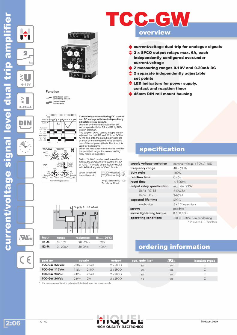
current/voltage dual trip for analogue signals
2 separate
set points
independently adjustable
2 measuring ranges 0-10V and 0-20mA DC
LED indicators for power supply,
contact and reaction timer
45mm DIN rail mount housing
supply voltage variation
frequency range
duty cycle
reaction time
reset time
output relay specification
Ue/Ie AC-15
Ue/Ie DC-13
expected life time
operating conditions
nominal voltage +10% / -15%
48 - 63 Hz
100%
0 - 5s
< 100ms
max. 6A 230V
240V/3A
24V/2A
-20 to +60°C non condensing
5 x 10⁶
operationsmechanical
SPCO
2 x SPCO output relays max. 6A, each
independently configured over/under
current/voltage
Gehäusetypenpart no supply output
TCC-GW 230Vac
TCC-GW 115Vac
TCC-GW 24Vac
115V~
24V~
24V=
230V~ 2 x SPCO
2 x SPCO
2 x SPCO
2 x SPCOTCC-GW 24Vdc
housing types
yes
yes
yes
yes
C
C
C
C
2,5VA
2,5VA
2,5VA
2W
sup. galv. iso*
yes
yes
yes
no
* The measurement is galvanically isolated from the power supplyinput
input
E2-M
E1-M
range resistance IN (20°C)MAX
0 - 20mA 50 Ohm 40mA
0 - 10V 98 kOhm 20V
Control relay for monitoring DC currentand DC voltage with two independentlyadjustable relay outputs.
tr,
tr
Under or over current function can beset independently for R1 and R2 by DIP-Switch selection.The setpoint (Hyst) can beadjusted for both R1 and R2 from 5-50%.At the end of the output relay changesas soon as the measured value exceedsone of the set points (Hyst). The time isvalid for both relays.When the measured value returns to withinthe permitted range, the correspondingrelay resets immediately.
Switch “I/Umin” can be used to enable ordisable the minimum level control (<4mAor <2V). This could be particularly usefulwith 4-20mA signals in function.
independently
“Over”
upper threshold: [ Y*(100+Hyst%) ] /100lower threshold: [ Y*(100-Hyst%) ] /100
Y= (Z*Setpoint%) /100Z= 10V or 20mA
Control relay activeControl relay passive
Contact closedContact open
Function
A1
11 21
12 22
14 24
+~
A2
M
E2
E1
-~
Supply U A1-A2=
>
=
>
R1 R2
U
11-14 21-24
R1
SetpointHyst.%
Hyst.%
trt=
t
Func:over
11-12 21-22
R2
11-14 21-24
R1
Func:under
11-12 21-22
R2
t t
t t
U
R1 R2
TCC-GW
Current/VoltageDualTrip
Hyst.% tr
R2I/UnSetpoint
230VAC
R1I/Un
Setpoint
UnderUnder
R2OverR1Over
25%
5% 0s 5s
5% 5%
50%50%
2,5s
I/Umin I/Umin
4mA
50%
100% 100%
2
DIN
U<
<
0-10V
I<
<
0-20mA
C US
screws
screw tightening torque 0,6..0,8Nm
pozidrive 1
* EN 60947-5-1 VDE 0435

2:07
overview
ICVICV
HIGH QUALITY ELECTRONICS
2009HIQUEL X01.00
specification
ordering information
sin
gle
phase
volta
ge
contro
l
Gehäusetypenpart no supply output
ICV 24Vac
ICV 115Vac
ICV 230Vac
DPCO
DPCO
DPCO
DPCOICV 400Vac
housing types
L
L
L
L
115V~
230V~
400V~
24V~ 2,5VA/1W
2,5VA/1W
2,5VA/1W
2,5VA/1W
sup. galv. iso*
yes
yes
yes
yes
* The measurement is galvanically isolated from the power supplyinput
Control relay activeControl relay passive
Contact closedContact open
Function
DIP-Switch: Autom.-Reset / Relay normal
over voltage with window over voltage with hysteresisU
SP1
I
W
R
W
U
SP1
H
R
I
U
SP1W
W
R
I
U
SP1
H
R
I
under voltage with window
inner voltage
under voltage with hysteresis
U
SP1
R
I
SP2
U
SP1
R
I
SP2
outer voltage
2
DIN
supply voltage variation
frequency range
duty cycle
repeat accuracy
output relay specification
Ue/Ie AC-15
Ue/Ie DC-13
expected life time
operating conditions
nominal voltage -20%..+10%
48 - 63 Hz
100%
<1%
max. 6A 230V~
24V/1,5A 115V/1,5A 230V/1,5A
24V/1A
-20 60 °C non condensing°C to
10 x 106
operations
8 x 10⁴
operations
mechanical
electrical
DPCO
input
E2-M
E1-M
E3-M
range resistance U (20°C)EMAX
0V - 45V 200 kOhm 75Vac
0V - 10V 30 kOhm 13Vac
0V - 450V 1,7 MOhm 550Vac
-
-
-
-
AC or DC voltage monitor
3 different voltage ranges
4 selectable base modes (over, under,
between setpoints, outside setpoints)
2 selectable measuring functions
automatic and manual reset selectable
Alarm memory function
output relay contact invertable
DPCOalarm relay
LED indicators for power supply, over
voltage and under voltage, failure and
status of the output relay, start-up &
reaction timer
22.5mm DIN rail mount housing
U<
<
0-480V
screw tightening torque 0,6..0,8Nm
* EN 60947-5-1 VDE 0435
U
100%0%
50
F
R1
SP1
ts
tr
0V
UNICV
230Vac
10s0s
5
5s0s
2,5
100%0%
SP2H
0% 25%
ts
tr
IN/OU
A/M
ac/dc
-/UN
-/OV
W/H
n/v
MR
M A1 A2
E2 E3
24 21 22
14 11 12
E1
4selectablebasemodes
over under
inner outer
manual-reset
direct current
hysteresis
relay inverted
autom.-reset
alternatingcurrent
window
relaynormal
DIP-Switch
/
/
/
/
/
/
M
H
dc
A
W
ac
v
OV
UN
n
-
-
12
11 21
14
R1
E3
A1
E2
E1
22 24
R1
~ ~+
~+
~+
MA2
~~ -
screws pozidrive 1

2:08
overview
TCV-HTCV-H
HIGH QUALITY ELECTRONICS
2009HIQUELX01.00
specification
ordering information
over/
under
volt
age
monit
or
AC or DC over or under voltage monitor
level and hysteresis adjustments
programmable latch/no latch alarm
LED indicators for power supply,
contact and reaction timer
45mm DIN rail mount housing
3 measuring ranges 0.5 - 600V RMS
DPCO output max. 6A
supply voltage variation
frequency range
duty cycle
start surge delay
reaction time
reset time
output relay specification
Ue/Ie AC-15
Ue/Ie DC-13
expected life time
operating conditions
nominal voltage +10% / -15%
48 - 63 Hz
100%
0 - 10s
0 - 5s
< 100ms
max. 6A 230V~
120V/4A 240V/3A
24V/2A
-20 to +60°C non condensing
mechanical
electrical
Gehäusetypenpart no supply output
TCV-H 230Vac
TCV-H 115Vac
TCV-H 24Vac
115V~
24V~
24V=
230V~ DPCO
DPCO
DPCO
DPCOTCV-H 24Vdc
housing types
yes
yes
yes
yes
C
C
C
C
2,5VA
2,5VA
2,5VA
2W
sup. galv. iso*
yes
yes
yes
no
* The measurement is galvanically isolated from the power supplyinput
input
E2-M
E1-M
E3-M
range resistance U (20°C)EMAX
3V - 60V 68 kOhm 130V
0,5V - 10V 3,9 kOhm 30V
30V - 600V 820 kOhm 660V
230VAC
U
R T
TCV-H
Over/Under Voltage Control
5
50
100%
50%
25
0
0
0 5
2,5
5
10
AC
LatchUnder
No LatchOver
U %n ts
t rHyst.
DC
1
2
S1Latch
R
U
Un%
noLatch
R
t s t st r t r
LatchS1
U
Un%
overvoltage
undervoltage
noLatch
R
R
t s t st r t r
1
1
2
2
3
3
4
4
Control relay activeControl relay passive
Contact closedContact open
Function1
2
3
4
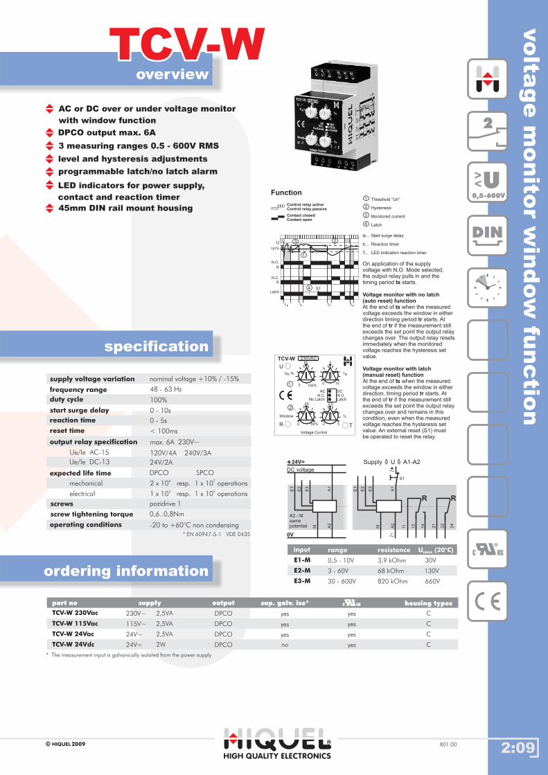
Threshold “Un”
Hysteresis
Monitored current
Latch
On the application of the supplyvoltage the output relay pulls inand the timing period starts.
At the end of , when the measuredvoltage exceeds the set point (Hyst),the timing period starts. At the endof if the measured value still exceedsthe set point the output relay changesover.
.
ts
Voltage monitor with no latch(auto reset) function
ts
trtr,
Voltage monitor with latch(manual reset) function.
The output relay resets imme-diately when the measured voltagereaches the hysteresis set value
At the end of , when the measuredvoltage exceeds the set threshold,timing period starts. At the end ofif the measured value still exceeds theset point the output relay changes overand remains in this condition, evenwhen the measured voltage reachesthe hysteresis set value. An externalreset (S1) must be operated to resetthe relay.
ts
tr tr
ts...
tr...
T...
Start surge delay
Reaction timer
LED indication reaction timer
A1
11 21
12 22
14 24
A2
M
E3
E2
E1
-~
A1
A2
M
E3
E2
E1
+24V=
DC voltage
A2 - Msamepotential
0V
Supply U A1-A2=
>
=
>
R R
+~S1
2
DIN
C US
U<
<
0,5-600V
DPCO SPCO
2 x 10⁶
resp. 1 x 10⁷
operations
1 x 10⁵
resp. 1 x 10⁵
operations
screws
screw tightening torque 0,6..0,8Nm
pozidrive 1
* EN 60947-5-1 VDE 0435
2:09
overview
TCV-WTCV-W
HIGH QUALITY ELECTRONICS
2009HIQUEL X01.00
specification
ordering information
volta
ge
monito
rw
indow
functio
n
AC or DC over or under voltage monitor
with window function
DPCO output max. 6A
level and hysteresis adjustments
3 measuring ranges 0.5 - 600V RMS
programmable latch/no latch alarm
LED indicators for power supply,
contact and reaction timer
45mm DIN rail mount housing
supply voltage variation
frequency range
duty cycle
start surge delay
reaction time
reset time
output relay specification
Ue/Ie AC-15
Ue/Ie DC-13
expected life time
operating conditions
nominal voltage +10% / -15%
48 - 63 Hz
100%
0 - 10s
0 - 5s
< 100ms
max. 6A 230V~
120V/4A 240V/3A
24V/2A
-20 to +60°C non condensing
mechanical
electrical
Gehäusetypenpart no supply output
TCV-W 230Vac
TCV-W 115Vac
TCV-W 24Vac
115V~
24V~
24V=
230V~ DPCO
DPCO
DPCO
DPCOTCV-W 24Vdc
housing types
yes
yes
yes
yes
C
C
C
C
2,5VA
2,5VA
2,5VA
2W
sup. galv. iso*
yes
yes
yes
no
* The measurement is galvanically isolated from the power supplyinput
input
E2-M
E1-M
E3-M
range resistance U (20°C)EMAX
3 - 60V 68 kOhm 130V
0,5 - 10V 3,9 kOhm 30V
30 - 600V 820 kOhm 660V
S1
t s t st r t r
Latch
U
Un%
N.C.
N.O.
R
R
4
1
3 2
T
50
25 2,5
5230VAC
U
R
TCV-W
Voltage Control
5 100%
50% 0
0
0 5
10
AC
LatchN.O.
No LatchN.C.
U %n ts
t rWindow
DC
1
2
Control relay activeControl relay passive
Contact closedContact open
Function1
2
3
4
Threshold “Un”
Hysteresis
Monitored current
Latch
ts...
tr...
T...
Start surge delay
Reaction timer
LED indication reaction timer
A1
11 21
12 22
14 24
A2
M
E3
E2
E1
-~
A1
A2
M
E3
E2
E1
+24V=
DC voltage
A2 - Msamepotential
0V
Supply U A1-A2=
>
=
>
R R
+~S1
On application of the supplyvoltage with N.O. Mode selected,the output relay pulls in and thetiming period starts.
if the measurement stillexceeds the set point
the hysteresis setvalue.
At the end of when the measuredvoltage exceeds the window in eitherdirection, timing period starts. Atthe end of if the measurement stillexceeds the set point the output relaychanges over and remains in thiscondition, even when the measuredvoltage reaches the hysteresis setvalue. An external reset (S1) mustbe operated to reset the relay.
ts
ts
trtr
At the end of when the measuredvoltage exceeds the window in eitherdirection timing period starts. Atthe end of
the output relaychanges over. The output relay resetsimmediately when the monitoredvoltage reaches
Voltage monitor with no latch(auto reset) function
ts
trtr
Voltage monitor with latch(manual reset) function
C US
2
DIN
U<
<
0,5-600V
DPCO SPCO
2 x 10⁶
resp. 1 x 10⁷
operations
1 x 10⁵
resp. 1 x 10⁵
operations
screws
screw tightening torque 0,6..0,8Nm
pozidrive 1
* EN 60947-5-1 VDE 0435
2:10
overview
TCV-PTCV-P
HIGH QUALITY ELECTRONICS
2009HIQUELX01.00
specification
ordering information
supply
volt
age
contr
ol
supply voltage ‘brown-out’ monitor
for 24V~, 115V~ and 230V~ supplies
SPCO output for post brown-out
control panel reset
LED indicators for power supply
and relay
22.5mm DIN rail mount housing
supply voltage variation
frequency range
duty cycle
repeat accuracy
nominal voltage +10% / -30%
48 - 63 Hz
100%
<1% of the selected range
output relay specification
Ue/Ie AC-15
Ue/Ie DC-13
expected life time
max. 12A 250V~
120V/2,5A 240V/2,5A
24V/2A
mechanical
electrical
11
R
12
14
A2
A1
+~
-~
Function
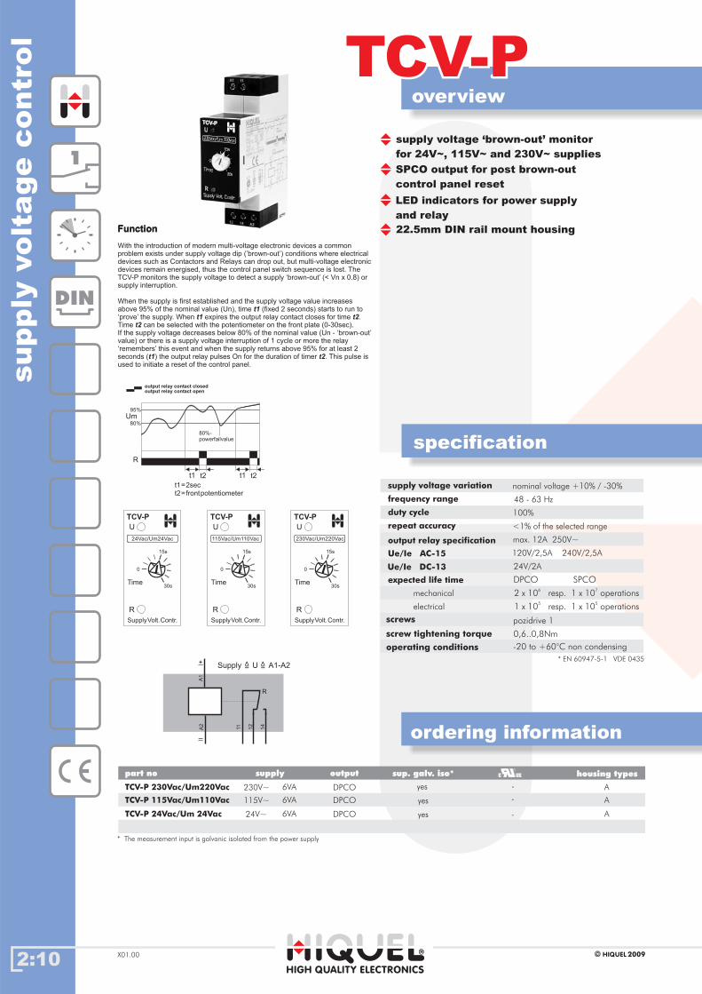
output relay contact closedoutput relay contact open
95%
80%
Um
R
80%-powerfailvalue
t1 t2 t1 t2
t1=2sect2=frontpotentiometer
Supply U A1-A2=
>
=
>
Gehäusetypenpart no supply output
TCV-P 24Vac/Um 24Vac
TCV-P 115Vac/Um110Vac
DPCO
DPCO
housing types
A
A115V~
230V~
6VA
6VA
sup. galv. iso*
yes
yes
yes
* The measurement input is galvanic isolated from the power supply
1
DIN
DPCO SPCO
2 x 10⁶
resp. 1 x 10⁷
operations
1 x 10⁵
resp. 1 x 10⁵
operations
SupplyVolt.Contr.
U
R
0
15s
30s
TCV-P
Time
24Vac/Um24Vac
SupplyVolt.Contr.
U
R
0
15s
30s
TCV-P
Time
115Vac/Um110Vac
SupplyVolt.Contr.
U
R
0
15s
30s
TCV-P
Time
230Vac/Um220Vac
Function
With the introduction of modern multi-voltage electronic devices a commonproblem exists under supply voltage dip (’brown-out’) conditions where electricaldevices such as Contactors and Relays can drop out, but multi-voltage electronicdevices remain energised, thus the control panel switch sequence is lost. TheTCV-P monitors the supply voltage to detect a supply ‘brown-out’ (< Vn x 0.8) orsupply interruption.
When the supply is first established and the supply voltage value increasesabove 95% of the nominal value (Un), time (fixed 2 seconds) starts to run to‘prove’ the supply. When expires the output relay contact closes for time .Time can be selected with the potentiometer on the front plate (0-30sec).If the supply voltage decreases below 80% of the nominal value (Un - ‘brown-out’value) or there is a supply voltage interruption of 1 cycle or more the relay‘remembers’ this event and when the supply returns above 95% for at least 2seconds ( ) the output relay pulses On for the duration of timer . This pulse isused to initiate a reset of the control panel.
t1
t1 t2
t2
t1 t2
screws
screw tightening torque
operating conditions
0,6..0,8Nm
-20 to +60°C non condensing
pozidrive 1
* EN 60947-5-1 VDE 0435
-
-
TCV-P 230Vac/Um220Vac DPCO A
24V~
6VA -

contro
lre
lays
2:11HIGH QUALITY ELECTRONICS
2009HIQUEL X01.00
module overviewmodule overview
DIN
C US
3
11
1 or 21 or 2

2:12
overview
ICPICP
HIGH QUALITY ELECTRONICS
2009HIQUELX01.00
specification
ordering information
3phase
monit
ori
ng
rela
y(p
hase
tophase
measure
ment)
Gehäusetypenpart no supply output
ICP 200...400Vac DPCO
housing types
L115-440V~ 30VA/1,5W no
sup. galv. iso*
-
supply voltage variation
frequency range
duty cycle
max. measure voltage
repeat accuracy
output relay specification
Ue/Ie AC-15
Ue/Ie DC-13
expected life time
operating conditions
nominal voltage -20%..+10%
48 - 63 Hz
100%
480V~
<1%
max. 6A 230V~
24V/1,5A 115V/1,5A 230V/1,5A
24V/1A
-20 +60 °C non condensing°C ..
10 x 106
operations
8 x 10⁴
operations
mechanical
electrical
DPCO
Control relay or voltage activeControl relay or voltage passive
Contact closedContact open
Function
DIP-Switch: autom.-Reset
neutral
asymmetry
L12
L23
L31
R
sequence
L12
L23
L31
N
R
R
L12
L23
L31
Asy
2
DIN
3 phase monitoring relay for 3x230/400V
detects phase failure, phase sequence
and phase asymmetry
detects phase failure with regenerated
voltage present
for power supply with or without neutral
connections
4 selectable base modes
3 selectable voltage measurement functions
automatical and manual reset selectable
selectable measuring range (150-440V)
Alarm memory function
DPCO alarm relay
LED indicators for supply voltage, alarm,
output relay status, reaction timer and
setting error
22.5mm DIN rail mount housing
3 selectablebase modes over under
inner
manual-reset
sequenceon
asymmetryon
neutral on
autom.-reset
DIP-Switch
/
/
/
/
/
/
M
AS
SQ
A
-
-
N
OV
UN
-
-
-
3
screws
screw tightening torque 0,6...0,8Nm
pozidrive 1
* EN 60947-5-1 VDE 0435
U
440V150V
R1
F
SP1
tr
E
A/M
-/SQ
-/N
-/OV
-/UN
-/AS
30%5%
15
5s0s
2,5
ICP200..400Vac
SP2H
AS
tr
MR
440V150V5% 25% IN/-
L1 L2 L3
N
24 21 22
14 11 12
300
12
11 21
14
R1
L3L2L1
22 24
R1
~
N
~
~~
* The measurement is galvanically isolated from the power supplyinput
The device recognizes alsothe regenerated voltage ofthe consumer, starting froma load size of 0,5kW and anAS attitude of 10%.
ICP 300...500Vac DPCO L180-550V~ 30VA/1,5W no -
2:13
overview
TCPTCP
HIGH QUALITY ELECTRONICS
2009HIQUEL X01.00
specification
ordering information
detects phase failure, phase sequence
and phase asymmetry
detects phase failure with
regenerated voltage present
SPCO or DPCO output max. 6A
fixed asymmetry alarmTCP / PCP >10%TCP-L / PCP-L >30%
no neutral connection required
adjustable reaction timer 0.1 - 10s
LED indicators for power supply,
relay and reaction timer
22.5 or 45mm DIN rail mount housing
or 11pin plug in housing
supply voltage variation
frequency range
duty cycle
reaction timer
reset time
output relay specification
Ue/Ie AC-15
Ue/Ie DC-13
expected life time
operating conditions
nominal voltage +10% / -15%
48 - 63 Hz
100%
0,1 - 10s
< 100ms
max. 6A 230V~
120V/4A 240V/3A
24V/2A
-20 to +60°C non condensing
mechanical
electrical
DPCO SPCO
2 x 10⁶
resp. 1 x 10⁷
operations
1 x 10⁵
resp. 1 x 10⁵
operations
Gehäusetypenpart no supply output housing types
TCP 3x400Vac
TCP 3x230Vac
TCP-S 3x400Vac
TCP-S 3x230Vac
PCP 3x400Vac
PCP 3x230Vac
TCP-L 3x400Vac
TCP-L 3x230Vac
PCP-L 3x400Vac
PCP-L 3x230Vac
3x 400V~
3x 230V~
3x 230V~
3x 230V~
3x 230V~
3x 230V~
3x 400V~
3x 400V~
3x 400V~
3x 400V~
2,5VA
2,5VA
2,5VA
2,5VA
2,5VA
2,5VA
2,5VA
2,5VA
2,5VA
2,5VA
DPCO
DPCO
DPCO
DPCO
DPCO
DPCO
DPCO
DPCO
SPCO
SPCO
yes
yes
yes
yes
no
no
no
no
no
no
C
C
B
B
G
G
C
C
G
G
R
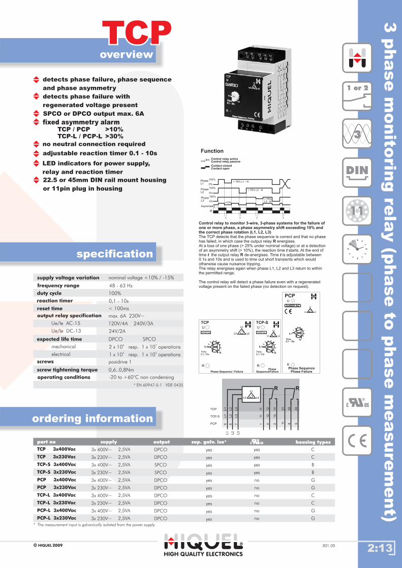
PhaseL1
100%
100%
100%
0%
0%
0%
< 75% L1 - N
< 75% L2 - N
>10%
< 75%L3 - N
t t t t
PhaseL2
PhaseL3
Asymmetry
Control relay activeControl relay passive
Contact closedContact open
Function
Phase Sequence / Failure
U
R
TCP
0,1
10
L3
L1
L23x400Vac
Time0,1-10s
11
111
21
11
12
41
2
22
8
14
314
24
9
L3
7L3
L3
TCP
TCP-S
PCP
L2
6L
2L
2
L1
5L
1L1
L3
L1
L2
R R
Control relay to monitor 3-wire, 3-phase systems for the failure ofone or more phase, a phase asymmetry shift exceeding 10% andthe correct phase rotation (L1, L2, L3)
R
R
The TCP detects that the phase sequence is correct and that no phasehas failed, in which case the output relay energises.At a loss of one phase (> 25% under nominal voltage) or at a detectionof an asymmetry shift (> 10%), the reaction time starts. At the end oftime the output relay de-energises. Time is adjustable between0.1s and 10s and is used to time out short transients which wouldotherwise cause nuisance tripping.The relay energises again when phase L1, L2 and L3 return to withinthe permitted range.
The control relay will detect a phase failure even with a regeneratedvoltage present on the failed phase (no detection on request).
t
t t
0.1
Time0,1 - 10s
10
Phase SequencePhase Failure
U
R
PCP
3x400V AC
L3
L1
L2
0,1
10
3x400Vac
Time0,1-10s
PhaseSequence/Failure
U
R
TCP-S
L3
L1
L2
DIN
C US
3
11
1 or 21 or 2
screws
screw tightening torque 0,6..0,8Nm
pozidrive 1
* EN 60947-5-1 VDE 0435
3phase
monito
ring
rela
y(p
hase
tophase
measure
ment)
sup. galv. iso*
yes
yes
yes
yes
yes
yes
yes
yes
yes
yes
* The measurement is galvanically isolated from the power supplyinput
2:14
specification
ordering information
TCP-SFTCP-SF
DIN
3
1 or 21 or 2
HIGH QUALITY ELECTRONICS
2009HIQUELX01.00
overview
detects phase failure and phase sequence
SPCO output max. 8A
measuring voltage without neutral
does not detect phase failure with
regenerated voltage present
LED indicators for power supply,
relay and reaction timer
22.5mm DIN rail mount housing
R
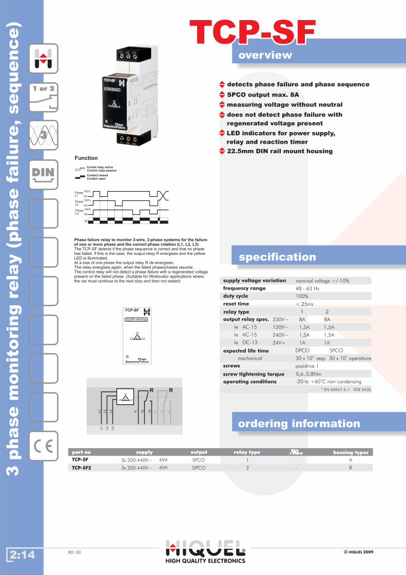
PhaseL1
100%
100%
100%
0%
0%
0%
PhaseL2
PhaseL3
Contol relay activeControl relay passive
Contact closedContact open
Function
3x200-440Vac
PhaseSequence/Failure
R
TCP-SF
L3
L1
L2
11 21
12
22
14
24
L3
L3
L2
L2
L1
L1
L3
L1
L2
R R
Phase failure relay to monitor 3-wire, 3-phase systems for the failureof one or more phase and the correct phase rotation (L1, L2, L3)The TCP-SF detects if the phase sequence is correct and that no phasehas failed. If this is the case, the output relay R energises and the yellowLED is illuminated.At a loss of one phase the output relay R de-energises.The relay energises again, when the failed phase/phases resume.The control relay will not detect a phase failure with a regenerated voltagepresent on the failed phase. (Suitable for lift/elevator applications wherethe car must continue to the next stop and then not restart) supply voltage variation
frequency range
duty cycle
reset time
relay type
output relay spec.
expected life time
operating conditions
nominal voltage +/-10%
48 - 63 Hz
100%
< 25ms
-20 to +60°C non condensing
mechanical
8A 8A
1 2
230V~
1,5A 1,5A120V~
1,5A 1,5A
1A 1A
240V~
24V=
Ie AC-15
Ie AC-15
Ie DC-13
DPCO SPCO
30 x 106
resp. 30 x 107
operations
screws
screw tightening torque 0,6..0,8Nm
pozidrive 1
* EN 60947-5-1 VDE 0435
Gehäusetypenpart no supply output
TCP-SF
TCP-SF2
3x 200-440V~ 6VA
3x 200-440V~ 6VA
SPCO
DPCO
housing types
A
B
relay type
1
23phase
monit
ori
ng
rela
y(p
hase
failure
,sequence)
-
-

2:15
TCP-MTCP-M
HIGH QUALITY ELECTRONICS
2009HIQUEL X01.00
specification
ordering information
3phase
failu
reand
therm
isto
rm
oto
rpro
tectio
n
2
DIN
3
PTC
C US
overview
detects phase failure, phase sequence
phase asymmetry and over-temperature
using PTC sensors
detects phase failure with
regenerated voltage present
DPCO output max. 6A
up to 6 PTC sensors in series
fixed asymmetry alarm >10%
no neutral connection required
adjustable reaction timer 0.1 - 10s
LED indicators for power supply,
relay and reaction timer
45mm DIN rail mount housing
R
PhaseL1
100%
100%
100%
0%
0%
0%
< 75% L1 - N
< 75% L2 - N
>10%
< 75%L3 - N
t t t t
PhaseL2
PhaseL3
Asymmetry
3x230V AC
Phase Sequence +Thermistor Motor Protection
U
R
TCP-M
0,1
Time0,1 - 10s
10
L3
L1
L2
1.
..
..
.6
T2
PTCDIN44081
T1
4000
R (Ohm)
1330
550
250
20
-20 0
TNF: nominal triggering temperature
TN
F-2
0
TN
F-5
TN
F+
5
TN
F+
15
°C
Control relay for phase failure and thermistor protection
R
The TCP-M monitors phase sequence, phase failure and phaseasymmetry, and is used with PTC sensors to provide over temperatureprotection for motors and other equipment. When the phase sequence iscorrect, all phases are detected, and the resistance of the PTC sensors onthe input T1 - T2 is within the correct range, the output relay energises.At a loss of one phase (> Vn x 0.75 ), or the detection of an asymmetryimbalance >10%, or when the resistance of the PTC sensors exceeds thetriggering threshold (3100 Ohm) the reaction time starts.t
At the end of time the output relayde-energises. Time is adjustablebetween 0.1s and 10s and is used totime out short transients which wouldotherwise cause nuisance tripping.The relay energises again whenphase L1, L2 and L3 return to thecorrect range and the resistance ofthe sensors falls below the resetthreshold (1650 Ohms).
The control relay will detect a phasefailure even with a regeneratedvoltage present on the failed phase(no detection on request).
t Rt
Control relay activeControl relay passive
Contact closedContact open
Function
11
T1
T2
21
12 22
14 24
L3
L3
L2
L2
L1
L1
PTCDIN 44081
(1...6)
L3
L1
L2
R R
Gehäusetypenpart no supply output
TCP-M 3x400Vac
TCP-M 3x230Vac
TCP-M 3x440Vac
3x 400V~
3x 230V~
3x 440V~
2,5VA
2,5VA
2,5VA
DPCO
DPCO
DPCO
housing types
yes
yes
no
C
C
C
supply voltage variation
frequency range
duty cycle
response/delay time
reset time
max. measuring voltage
max. resistance
triggering threshold
reset threshold
short circuit detection
output relay specification
Ue/Ie AC-15
Ue/Ie DC-13
expected life time
operating conditions
nominal voltage +10% / -15%
48 - 63 Hz
100%
< 300ms
< 500ms
< 2,5V
1500 Ohm (6 sensors)
3100 Ohm
1650 Ohm
0 - 20 Ohm
max. 6A 230V~
120V/4A 240V/3A
24V/2A
-20 to 60°C non condesning
mechanical
electrical
DPCO SPCO
2 x 10⁶
resp. 1 x 10⁷
operations
1 x 10⁵
resp. 1 x 10⁵
operations
* EN 60947-5-1 VDE 0435
sup. galv. iso*
yes
yes
yes
* The measurement is galvanically isolated from the power supplyinput

2:16
overview
ICPVICPV
HIGH QUALITY ELECTRONICS
2009HIQUELX01.00
specification
ordering information
2
DIN
U
260V80V
170V
170V
R1
F
SP1
t
SQ
A/M
-/SQ
-/-
-/OV
-/UN
1/3
60s0s
30s
5s0s
2,5s
ICPV
SP2H
te
tr
MR
260V80V5% 25% IN/ -
OV
UN
115..230Vac
L1 L2 L3
N
24 21 22
14 11 12
12
11 21
14
R1
L3L2L1
22 24
R1
~
N
~
~~
1Phase
L
3PhaseL2
L1
L3
Gehäusetypenpart no supply output housing typessup. galv. iso*
3phase
monit
ori
ng
rela
y(p
hase
toneutr
alm
easure
ment)
supply voltage variation
frequency range
duty cycle
max. measure voltage
repeat accuracy
output relay specification
Ue/Ie AC-15
Ue/Ie DC-13
expected life time
operating conditions
nominal voltage -20%..+10%
48 - 63 Hz
100%
480V~
<1%
max. 6A 230V~
24V/1,5A 115V/1,5A 230V/1,5A
24V/1A
-20 +60 °C non condensing°C ..
10 x 106
operations
8 x 10⁴
operations
mechanical
electrical
DPCO
screws
screw tightening torque 0,6..0,8Nm
pozidrive 1
* EN 60947-5-1 VDE 0435
3
Control relay activeControl relay or voltage passive
Contact closedContact open
Function
DIP-Switch: autom.-Reset
neutral
L12
L23
L31
R
sequence
L12
L23
L31
N
R
ICPV 115..230Vac DPCO - Lno
3 phase monitoring relay
detects phase failure, phase sequence
3 phase monitoring with single or
3 phase connection
4 selectable base modes
3 selectable voltage measurement functions
automatical and manual reset selectable
selectable measuring range (80-260V)
Alarm memory function
DPCO alarm relay
22.5mm DIN rail mount housing
115-230V 25VA/1,5W~
LED indicators for power supply, failure,
phase sequence, over and under voltage,
output relay status and reaction timer
* The measurement is galvanically isolated from the power supplyinput
L1-N 230V AC 3x230V/400VUs = Un x 0,7
Phase Failure
U
R
TCP -V
0,1
Time0,1 - 10s
10
2:17
overview
TCP-V/PCP-VTCP-V/PCP-V
HIGH QUALITY ELECTRONICS
2009HIQUEL X01.00
specification
ordering information
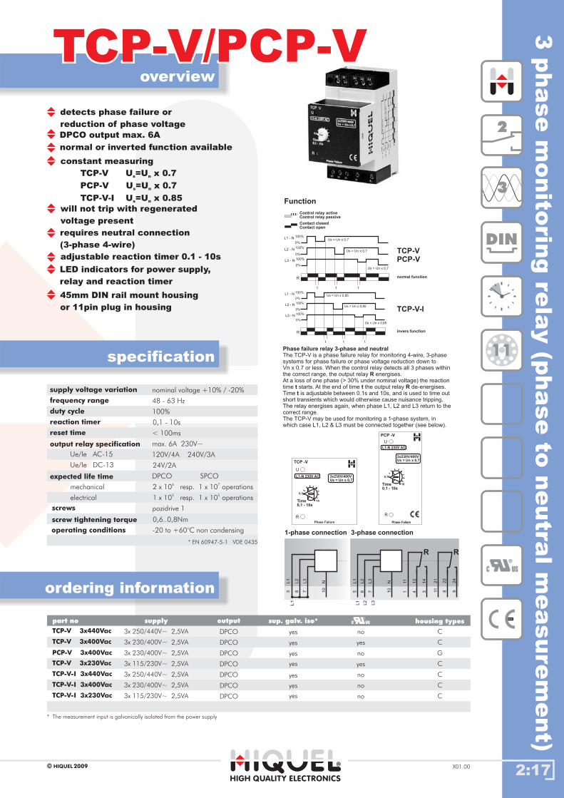
detects phase failure or
reduction of phase voltage
DPCO output max. 6A
normal or inverted function available
constant measuring
TCP-V U =U x 0.7
PCP-V U =U x 0.7
TCP-V-I U =U x 0.85
s n
s n
s n
requires neutral connection
(3-phase 4-wire)
will not trip with regenerated
voltage present
adjustable reaction timer 0.1 - 10s
LED indicators for power supply,
relay and reaction timer
45mm DIN rail mount housing
or 11pin plug in housing
supply voltage variation
frequency range
duty cycle
reaction timer
reset time
output relay specification
Ue/Ie AC-15
Ue/Ie DC-13
expected life time
operating conditions
nominal voltage +10% / -20%
48 - 63 Hz
100%
0,1 - 10s
< 100ms
max. 6A 230V~
120V/4A 240V/3A
24V/2A
-20 to +60°C non condensing
mechanical
electrical
DPCO SPCO
2 x 10⁶
resp. 1 x 10⁷
operations
1 x 10⁵
resp. 1 x 10⁵
operations
Gehäusetypenpart no supply output housing types
TCP-V 3x440Vac
TCP-V 3x400Vac
TCP-V 3x230Vac
TCP-V-I 3x440Vac
TCP-V-I 3x400Vac
TCP-V-I 3x230Vac
3x 250/440V~
3x 230/400V~
3x 115/230V~
3x 250/440V~
3x 230/400V~
3x 115/230V~
2,5VA
2,5VA
2,5VA
2,5VA
2,5VA
2,5VA
2,5VA
DPCO
DPCO
DPCO
DPCO
DPCO
DPCO
DPCO
no
no
no
no
no
yes
yes
C
C
C
C
C
C
PCP-V 3x400Vac 3x 230/400V~ G
NL3
L2
L1
L1
11 21
12 22
14 24
NL3
L3
L2
L2
L1
L1
R R
10
765 1 11
4 83 910
765
R
L1 - N 100%
100%
100%
0%
0%
0%
Us = Un x 0,7
Us = Un x 0,7
Us = Un x 0,7
t t t
L2 - N
L3 - N
Control relay activeControl relay passive
Contact closedContact open
normal function
invers function
TCP-V-I
TCP-VPCP-V
Function
R
L1 - N 100%
100%
100%
0%
0%
0%
Us = Un x 0,85
Us = Un x 0,85
Us = Un x 0,85
t t t
L2 - N
L3 - N
1-phase connection 3-phase connection
Phase Failure
3x230V/400VUs = Un x 0,7
L1-N 230V AC
0,1
Time0,1 - 10s
10
PCP -V
U
R
Phase failure relay 3-phase and neutral
R
t t Rt
The TCP-V is a phase failure relay for monitoring 4-wire, 3-phasesystems for phase failure or phase voltage reduction down toVn x 0.7 or less. When the control relay detects all 3 phases withinthe correct range, the output relay energises.At a loss of one phase (> 30% under nominal voltage) the reactiontime starts. At the end of time the output relay de-energises.Time is adjustable between 0.1s and 10s, and is used to time outshort transients which would otherwise cause nuisance tripping.The relay energises again, when phase L1, L2 and L3 return to thecorrect range.The TCP-V may be used for monitoring a 1-phase system, inwhich case L1, L2 & L3 must be connected together (see below).
C US
2
DIN
3
11
screws
screw tightening torque 0,6..0,8Nm
pozidrive 1
* EN 60947-5-1 VDE 0435
3phase
monito
ring
rela
y(p
hase
toneutra
lm
easure
ment)
sup. galv. iso*
yes
yes
yes
yes
yes
yes
yes
* The measurement is galvanically isolated from the power supplyinput
2:18
overview
TCP-LC/TCP-LSTCP-LC/TCP-LS
HIGH QUALITY ELECTRONICS
2009HIQUELX01.00
specification
ordering information
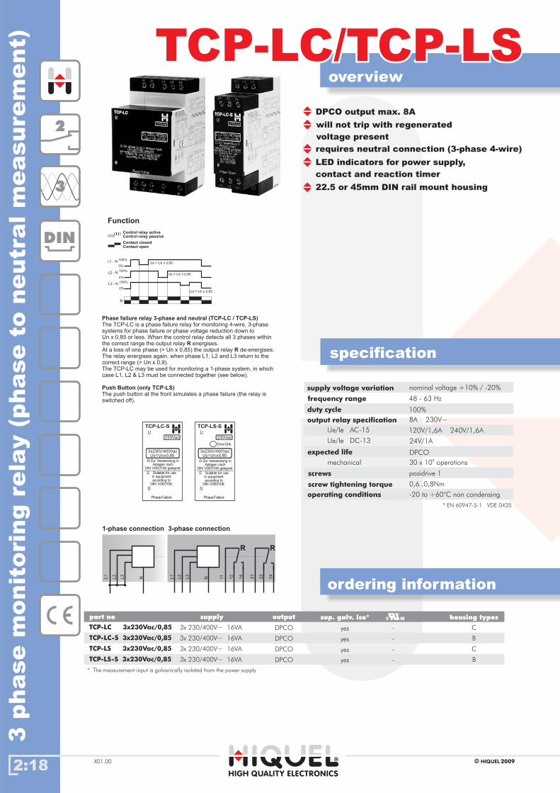
DPCO output max. 8A
requires neutral connection (3-phase 4-wire)
will not trip with regenerated
voltage present
LED indicators for power supply,
contact and reaction timer
22.5 or 45mm DIN rail mount housing
supply voltage variation
frequency range
duty cycle
output relay specification
Ue/Ie AC-15
Ue/Ie DC-13
expected life
operating conditions
nominal voltage +10% / -20%
48 - 63 Hz
100%
8A 230V~
120V/1,6A 240V/1,6A
24V/1A
-20 to +60°C non condensing
30 x 106
operationsmechanical
DPCO
Gehäusetypenpart no supply output housing types
3x 230/400V~ 16VA
3x 230/400V~ 16VA
3x 230/400V~ 16VA
3x 230/400V~ 16VA
DPCO
DPCO
DPCO
DPCO
-
-
-
-
TCP-LC 3x230Vac/0,85
TCP-LC-S 3x230Vac/0,85
TCP-LS 3x230Vac/0,85
TCP-LS-S 3x230Vac/0,85
C
B
C
B
R
L1 - N 100%
100%
100%
0%
0%
0%
Us = Un x 0,85
Us = Un x 0,85
Us = Un x 0,85
L2 - N
L3 - N
Control relay activeControl relay passive
Contact closedContact open
Function11 21
12 22
14 24
NL3
L2
L1
R R
1-phase connection 3-phase connection
NL3
L2
L1
Phase failure relay 3-phase and neutral (TCP-LC / TCP-LS)
RR
Push Button (only TCP-LS)
The TCP-LC is a phase failure relay for monitoring 4-wire, 3-phasesystems for phase failure or phase voltage reduction down toUn x 0,85 or less. When the control relay detects all 3 phases withinthe correct range the output relay energises.At a loss of one phase (> Un x 0,85) the output relay de-energises.The relay energises again, when phase L1, L2 and L3 return to thecorrect range (> Un x 0,9).The TCP-LC may be used for monitoring a 1-phase system, in whichcase L1, L2 & L3 must be connected together (see below).
The push button at the front simulates a phase failure (the relay isswitched off).
2
DIN
3
3x230V/400VacUs=Unx0,85
TCP-LC-S
PhaseFailure
U
R
230Vac
D:Zur Verwendung inAnlagen nach
DIN VDE0108 geeignet.
E: Suitable for usein equipmentaccording to
DIN VDE0108.
ErrorChk
TCP-LS-S
PhaseFailure
3x230V/400VacUs=Unx0,85
U
R
D:Zur Verwendung inAnlagen nach
DIN VDE0108 geeignet.
E: Suitable for usein equipmentaccording to
DIN VDE0108.
230Vac
screws
screw tightening torque 0,6..0,8Nm
pozidrive 1
* EN 60947-5-1 VDE 0435
3phase
monit
ori
ng
rela
y(p
hase
toneutr
alm
easure
ment)
sup. galv. iso*
yes
yes
yes
yes
* The measurement is galvanically isolated from the power supplyinput

2:19
overview
TCP-3NTCP-3N
HIGH QUALITY ELECTRONICS
2009HIQUEL X01.00
specification
ordering information
DIN
3
1+2for 3-wire and 4-wire 3-phase supplies
3 phase monitoring relay for
3x230/400Vmonitors phase sequence
measures phase to phase voltage
(adjustable from 110V to 440V)
detects neutral connection
(selectable by a DIP-switch)
monitors asymmetry (adjustable from
5% to 30%, selectable by DIP-switch)
22.5 or 45mm DIN rail mount housing
supply voltage variation
frequency range
duty cycle
relay type
output relay spec.
expected life time
operating conditions
nominal voltage +/-10%
48 - 63 Hz
100%
-20 to +60°C non condensing
10 x 106
operationsmechanical
DPCO
6A
1
230V~
1A120V~
1A
1A
240V~
24V=
Ie AC-15
Ie AC-15
Ie DC-13
6A
2
1,5A
1,5A
1,0A
screws
screw tightening torque 0,6..0,8Nm
pozidrive 1
* EN 60947-5-1 VDE 0435
Contol relay activeControl relay passive
Contact closedContact open
Function
R
L12
L23
L31
N
Asy.
toff toff toff toff toff toff
<Umin
<Umin
<Umin
11 21
12 22
14 24
NL3
L2
L1
R R
L3
L1
L2
Control relay to monitor 3-wire and 4-wire 3-phase supplies forthe failure of one or more phase, the correct phase rotation andthe existence of a neutral connection.The TCP-3N also measures the phase to phase voltages andcalculates the asymmetry. Only if there is no failure the outputrelay energises.
With the “Umin” potentiometer the minimum phase to phase voltageis selected between 110V and 440V, with the “Asy.” potentiometer themaximum asymmetry is chosen from 5% to 30%. The monitoring ofthe neutral connection and the asymmetry is selectable by twoDIP-switches.If the monitoring of the neutral connection is disabled, the neutralconnection is not required. Two different off-delay times are selectableby DIP-switch (1s or 5s).
Umin
1s
U
R
TCP-3N
110V
440V
Asy.
5%
30%
5s
On
N Off
Asy.Off
toffOn
PhaseControl
230VAC
PhaseControl
onAsy.
U
R
TCP-3N2
5%
30%
110V
440V
Umin
Asy. off
onN
off
1stoff
5s
Gehäusetypenpart no supply output
TCP-3N
TCP-3N2
3x 110-440V~
3x 110-440V~
30VA
30VA
SPCO
DPCO
housing types
B
C
relay type
1
2
3phase
monito
ring
rela
y(p
hase
toneutra
lm
easure
ment)
-
-
A load from 0,5kWdetects the devicewith a AS-setting< 10% and thereverse voltage ofconsumers.
detects phase failure with
regenerated voltage present
2:20
overview
ICLICL
HIGH QUALITY ELECTRONICS
2009HIQUELX01.00
specification
ordering information
2
DIN
Gehäusetypenpart no supply output housing typessup. galv. iso*
supply voltage variation
frequency range
duty cycle
delay time
reset time
output relay specification
expected life time
operating conditions
mechanical
electrical
screws
screw tightening torque
* EN 60947-5-1 VDE 0435
U
5s0s
2,5s
5s
R1
F
R2
S1
S2
A/M
n/vR2
n/vR1
S1/S12
FI/EM
100K100R
2,5s
ICL
SE
MR
10s0s
S3
230Vac
tr
te/ AL
0s 5s
10K
tr+te AL
S3 A1 A2
C
24 21 22
14 11 12
S1 S2
12
11 21
14
R1
S3
A1
S2
S1
22 24
R2
CA2
~
~
liquid
levelcontr
ol,
3le
vels
,m
in.or
max.ala
rm
0,6..0,8Nm
nominal voltage -20%..+10%
48 - 63 Hz
100%
<1%
max. 6A 230V~
24V/1,5A 115V/1,5A 230V/1,5A
24V/1A
-20 +60 °C°C ..
10 x 106
8 x 10⁴
SPCO
pozidrive 1
non condensing
operations
operations
R2
U
R1
S3
S1IMMERSEDNOT IMMERSED
IMMERSEDNOT IMMERSED
R2
U
R1
S3
S1
IMMERSED
NOT IMMERSED
IMMERSEDNOT IMMERSED
IMMERSEDNOT IMMERSED
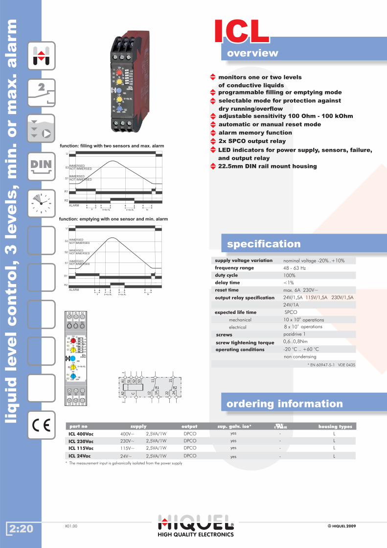
function: filling with two sensors and max. alarm
function: emptying with one sensor and min. alarm
ICL 24Vac Lyes -
ICL 115Vac
ICL 230Vac
ICL 400Vac
yes
yes
yes
L
L
L
-
-
-
DPCO
DPCO
DPCO
DPCO
24V~
115V~
230V~
2,5VA/1W
2,5VA/1W
2,5VA/1W
400V~ 2,5VA/1W
programmable filling or emptying mode
monitors one or two levels
of conductive liquids
LED indicators for power supply, sensors, failure,
and output relay
22.5mm DIN rail mount housing
selectable mode for protection against
dry running/overflow
adjustable sensitivity 100 Ohm - 100 kOhm
automatic or manual reset mode
ALARM
ALARM
* The measurement is galvanically isolated from the power supplyinput
alarm memory function
2x SPCO output relay

2:21
overview
TCLTCL
HIGH QUALITY ELECTRONICS
2009HIQUEL X01.00
specification
ordering information
liquid
levelcontro
l,2
levels
monitors one or two levels
of conductive liquids
DPCO output max. 6A
programmable filling or emptying mode
programmable sensitivity 250 Ohm - 100 kOhm
or 50 kOhm - 1 MOhm
LED indicators for power supply,
relay and reaction timer
45mm DIN rail mount housing or
11pin plug in housing
supply voltage variation
frequency range
duty cycle
delay time
reset time
max measuring voltage
max measuring current
probes
output relay specification
Ue/Ie AC-15
Ue/Ie DC-13
expected life time
operating conditions
nominal voltage +10% / -20%
48 - 63 Hz
100%
1s (fixed)
< 100ms
± 5,3V
~ 5mA
cable length max. 100m
max. 6A 230V~
120V/4A 240V/3A
24V/2A
-20 to +60°C non condensing
mechanical
electrical
DPCO SPCO
2 x 10⁶
resp. 1 x 10⁷
operations
1 x 10⁵
resp. 1 x 10⁵
operations
15
25
16
A2
A1
26
18
28
S2
S1
C
U
S1Level
filling
emptying
R
R
R
R
1
1
2
2
2
3
3
4
4
4
5
5
5
max. level
min. level
monitored level
Output relay, emptying function
Output relay, filling function
Control relay to monitor the level ofconductive liquids
1 levelSingle PointSensingusing 2 Sensors
C S1
2 levelTwo PointSensingusing 3 Sensors
U
Max. S2
S1Min.
filling
emptying
C S1 S2
Control relay activeControl relay passive
Contact closedContact open
Function
3
+~
-~
Supply U A1-A2=
>
=
>
R R
The TCL controls the level ofconductive liquids in aconductive or non-conductivecontainer and works bypassing a low voltage throughthe liquid from a suitable probeto an earth return which caneither be the container oranother probe.
The relay changes over eachtime the liquid contacts C andS1.
The relay changes over eachtime the liquid contacts C, S1and S2.The relay resets when theliquid level returnsbelow S1.
The polarity of the sensorvoltage is periodically reversedand is sufficiently low to avoidelectrolytic action between theprobes.
Single point sensing:
Two point sensing:
Note:
Do not make a connectionbetween A2 and C when usingTCL without galvanic isolation.(DC supplied versions)
Gehäusetypenpart no supply ouput housing types
TCL 230Vac
PCL 230Vac
TCL 115Vac
PCL 115Vac
TCL 24Vac
PCL 24Vac
TCL 24Vdc
PCL 24Vdc
230V~
230V~
115V~
115V~
24V~
24V~
24V=
24V=
DPCO
DPCO
DPCO
DPCO
DPCO
DPCO
DPCO
DPCO
C
C
C
C
G
G
G
G
2,5VA
2,5VA
2,5VA
2,5VA
2,5VA
2,5VA
2W
2W
sup. galv. iso*
yes
yes
yes
yes
yes
yes
no
no
* The measurement is galvanically isolated from the power supply.input
2
DIN
11
230VAC
LevelFunc.Sens.
Level Control
twolevels
emptying
filling
U
R
TCL
0
50
100%
onelevel
C
C
S1
S1S2
highlow
50K -1M
250 -100K
screws
screw tightening torque 0,6..0,8Nm
pozidrive 1
* EN 60947-5-1 VDE 0435
-
-
-
-
-
-
-
-
overview
TCL-LCTCL-LC
HIGH QUALITY ELECTRONICS
2008HIQUELX01.00
specification
ordering information
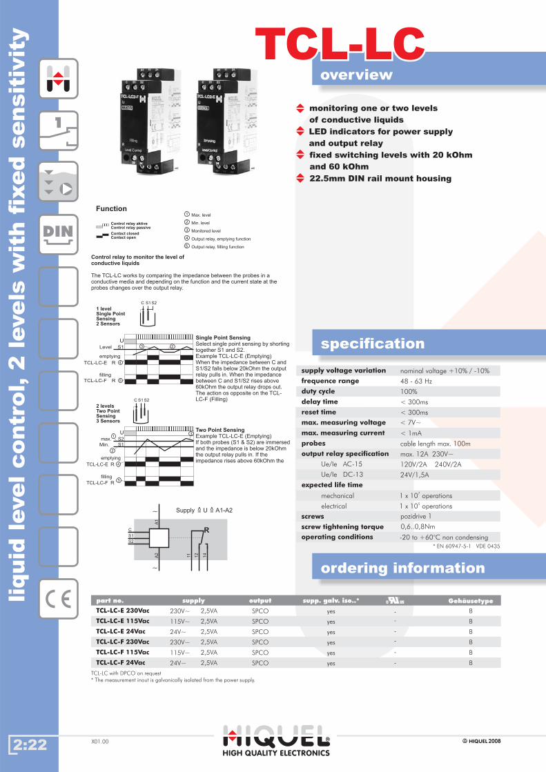
monitoring one or two levels
of conductive liquids
LED indicators for power supply
and output relay
fixed switching levels with 20 kOhm
and 60 kOhm
22.5mm DIN rail mount housing
operating conditions -20 to +60°C non condensing
supply voltage variation
frequence range
duty cycle
delay time
reset time
max. measuring voltage
max. measuring current
probes
output relay specification
Ue/Ie AC-15
Ue/Ie DC-13
expected life time
nominal voltage +10% / -10%
48 - 63 Hz
100%
< 300ms
< 300ms
< 7V~
< 1mA
cable length max. 100m
max. 12A 230V~
120V/2A 240V/2A
24V/1,5A
mechanical
electrical
Gehäusetypenpart no. supply output
TCL-LC-E 230Vac
TCL-LC-F 230Vac
TCL-LC-E 115Vac
TCL-LC-F 115Vac
TCL-LC-E 24Vac
TCL-LC-F 24Vac
230V~
115V~
115V~
24V~
24V~
SPCO
SPCO
SPCO
SPCO
SPCO
SPCO
Gehäusetype
B
B
B
B
B
B
230V~ 2,5VA
2,5VA
2,5VA
2,5VA
2,5VA
2,5VA
supp. galv. iso..*
yes
yes
yes
yes
yes
yes
TCL-LC with DPCO on request
* The measurement inout is galvanically isolated from the power supply.
1
2
3
4
5
Max. level
Min. level
Monitored level
Output relay, emptying function
Output relay, fillling function
Control relay to monitor the level ofconductive liquids
between the probes in aThe TCL-LC works by comparing the impedanceconductive media and depending on the function and the current state at theprobes changes over the output relay.
Control relay aktiveControl relay passive
Contact closedContact open
Function
1
DIN
1 x 10 operations7
1 x 10 operations5
U
S1Level
filling
emptying
R
R
23
4
5
1 levelSingle PointSensing2 Sensors
C S1 S2
TCL-LC-E
TCL-LC-F
R
R
1
2
4
5
2 levelsTwo PointSensing3 Sensors
U
max. S2
S1Min.
filling
emptying
C S1 S2
3
TCL-LC-E
TCL-LC-F
11
A2
A1
12
14
S2
S1
C
~
~
Supply U A1-A2=
>
=
>
R
Single Point Sensing
Two Point Sensing
Select single point sensing by shortingtogether S1 and S2.Example TCL-LC-E (Emptying)When the impedance between C andS1/S2 falls below 20kOhm the outputrelay pulls in. When the impedancebetween C and S1/S2 rises above60kOhm the output relay drops out.The action os opposite on the TCL-LC-F (Filling)
Example TCL-LC-E (Emptying)If both probes (S1 & S2) are immersedand the impedance is below 20kOhmthe output relay pulls in. If theimpedance rises above 60kOhm the
2:22
liquid
levelcontr
ol,
2le
vels
wit
hfi
xed
sensit
ivit
y
screws
screw tightening torque 0,6..0,8Nm
pozidrive 1
* EN 60947-5-1 VDE 0435
-
-
-
-
-
-
2:23
overview
TCL-3TCL-3
HIGH QUALITY ELECTRONICS
2009HIQUEL X01.00
specification
ordering information
liquid
levelcontro
l,3
levels
onelevel
U
R1R2
R3NO
NC
S1
S2
S3 max. or min.
1
2
Output relay, function emptying
Output relay, function filling
1 2
twolevels
U
R1R2
S1
emptying filling
S2
S3
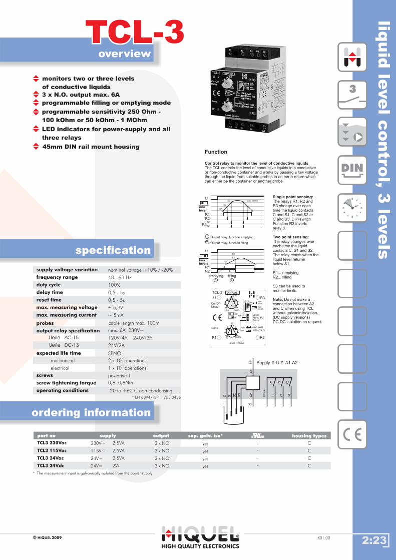
Control relay to monitor the level of conductive liquidsThe TCL controls the level of conductive liquids in a conductiveor non-conductive container and works by passing a low voltagethrough the liquid from suitable probes to an earth return whichcan either be the container or another probe.
Function
The relays R1, R2 andR3 change over eachtime the liquid contactsC and S1, C and S2 orC and S3. DIP-switchFunction R3 invertsrelay 3.
The relay changes overeach time the liquidcontacts C, S1 and S2.The relay resets when theliquid level returnsbelow S1.
R1... emptyingR2... filling
S3 can be used tomonitor limits.
Single point sensing:
Two point sensing:
Note: Do not make aconnection between A2and C when using TCLwithout galvanic isolation.(DC supply versions)DC-DC isolation on request
C1
-3
R1
R2
R3
A2
A1
14
24
34
S2
S3
S1
C
+~
-~
Supply U A1-A2=
>
=
>
monitors two or three levels
of conductive liquids
3 x N.O. output max. 6A
programmable filling or emptying mode
programmable sensitivity 250 Ohm -
100 kOhm or 50 kOhm - 1 MOhm
LED indicators for power-supply and all
three relays
45mm DIN rail mount housing
supply voltage variation
frequency range
duty cycle
delay time
reset time
output relay specification
Ue/Ie AC-15
Ue/Ie DC-13
expected life time
operating conditions
nominal voltage +10% / -20%
48 - 63 Hz
100%
0,5 - 5s
0,5 - 5s
max. 6A 230V~
120V/4A 240V/3A
24V/2A
-20 to +60°C non condensing
2 x 10⁷
operations
1 x 10⁵
operations
mechanical
SPNO
electrical
max. measuring voltage
max. measuring current
probes
~ 5mA
cable length max. 100m
± 5,3V
Gehäusetypenpart no supply output
TCL3 230Vac
TCL3 115Vac
TCL3 24Vac
115V~
24V~
24V=
230V~ 3 x NO
3 x NO
3 x NO
3 x NOTCL3 24Vdc
housing types
C
C
C
C
2,5VA
2,5VA
2,5VA
2W
sup. galv. iso*
yes
yes
yes
yes
* The measurement is galvanically isolated from the power supplyinput
3
DIN
230VAC
R3
R1 R2
TCL-3
Level Control
2,5
100%
50
10
Sens.Func. R3Level
high
low
50K -1M
250 -100K
NCR3
NO
twolevels
onelevel
UC
S1S2S3
On-/Off-Delay
Sens.
0,5 5sec
screws
screw tightening torque 0,6..0,8Nm
pozidrive 1
* EN 60947-5-1 VDE 0435
-
-
-
-
2:24
overview
TETTET
HIGH QUALITY ELECTRONICS
2009HIQUELX01.00
specification
ordering information
ele
ctr
onic
alth
erm
osta
t
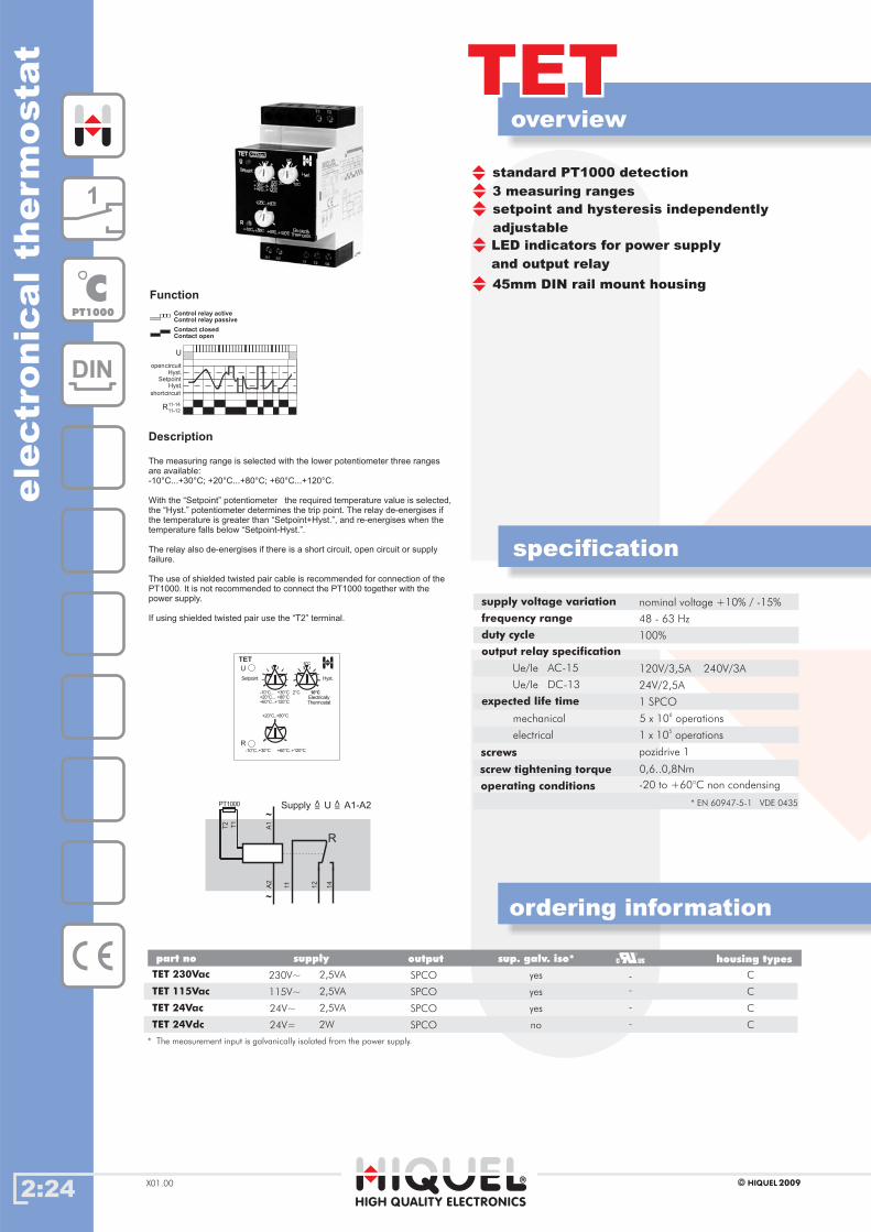
standard PT1000 detection
3 measuring ranges
setpoint and hysteresis independently
adjustable
LED indicators for power supply
and output relay
45mm DIN rail mount housing
supply voltage variation
frequency range
duty cycle
output relay specification
Ue/Ie AC-15
Ue/Ie DC-13
expected life time
operating conditions
nominal voltage +10% / -15%
48 - 63 Hz
100%
120V/3,5A 240V/3A
24V/2,5A
-20 to +60°C non condensing
5 x 10⁶
operations
1 x 10⁵
operations
mechanical
1 SPCO
electrical
Control relay activeControl relay passive
Contact closedContact open
Function
Supply U A1-A2=
>
=
>
A1
11
12
14
A2
~
R
~PT1000
T1
T2
U
SetpointHyst.
Hyst.
11-14
11-12R
opencircuit
shortcircuit
U
R
TET
-10°C..+30°C +60°C..+120°C
+20°C..+80°C
-10°C... +30°C+20°C... +80°C+60°C...+120°C
6°C
2°C 10°CElectricallyThermostat
Setpoint Hyst.
TET 230Vac 2,5VA SPCO
SPCO
C
TET 115Vac
TET 24Vac 24V~
24V=
2,5VA115V~
2,5VA
2WTET 24Vdc
C
C
C
yes
yes
yes
no
230V~
Gehäusetypenpart no supply output housing typessup. galv. iso*
* The measurement is galvanically isolated from the power supply.input
1
DIN
CPT1000
SPCO
SPCO
Description
The measuring range is selected with the lower potentiometer three rangesare available:-10°C...+30°C; +20°C...+80°C; +60°C...+120°C.
With the “Setpoint” potentiometer the required temperature value is selected,the “Hyst.” potentiometer determines the trip point. The relay de-energises ifthe temperature is greater than “Setpoint+Hyst.”, and re-energises when thetemperature falls below “Setpoint-Hyst.”.
The relay also de-energises if there is a short circuit, open circuit or supplyfailure.
The use of shielded twisted pair cable is recommended for connection of thePT1000. It is not recommended to connect the PT1000 together with thepower supply.
If using shielded twisted pair use the “T2” terminal.
screws
screw tightening torque 0,6..0,8Nm
pozidrive 1
* EN 60947-5-1 VDE 0435
-
-
-
-
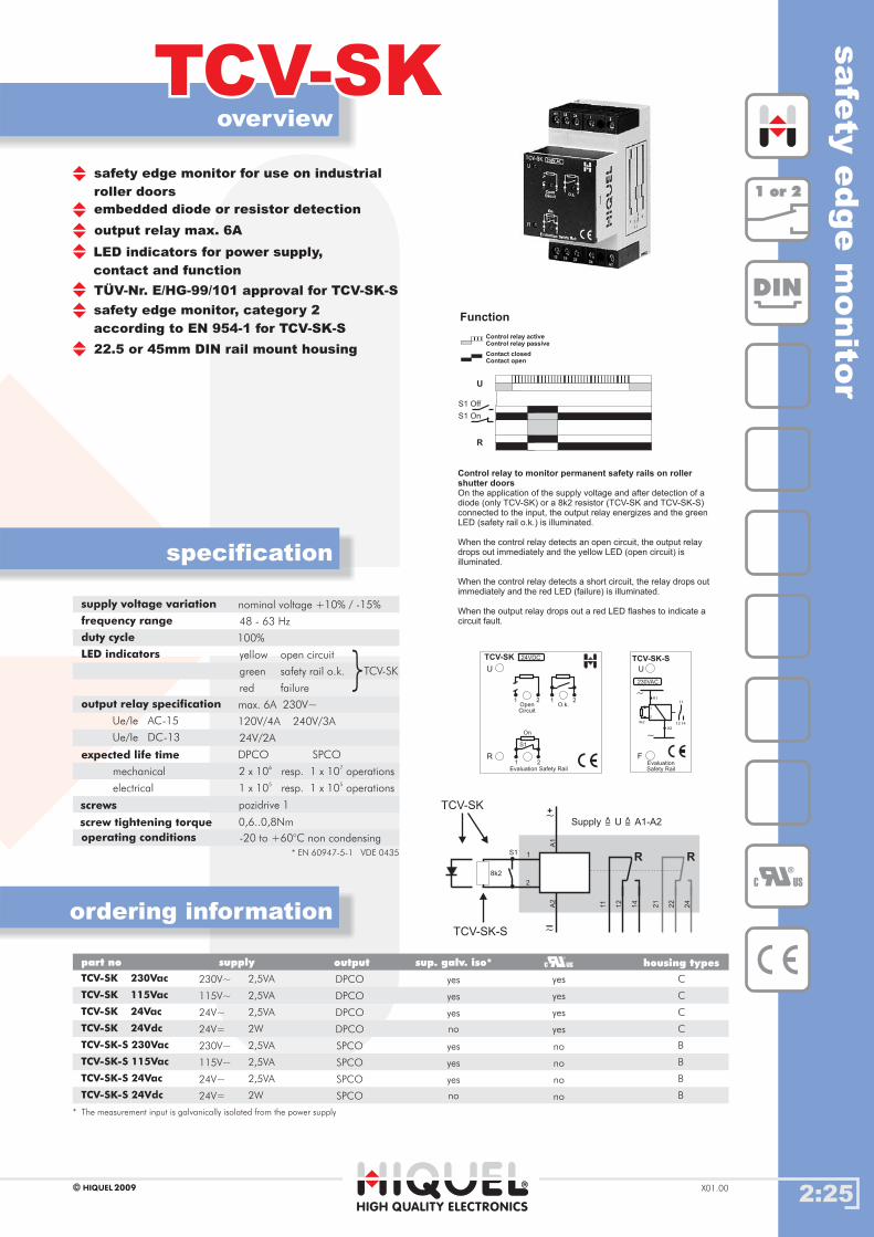
2:25
overview
TCV-SKTCV-SK
HIGH QUALITY ELECTRONICS
2009HIQUEL X01.00
specification
ordering information
Gehäusetypenpart no supply output housing types
safety edge monitor for use on industrial
roller doors
embedded diode or resistor detection
output relay max. 6A
LED indicators for power supply,
contact and function
TÜV-Nr. E/HG-99/101 approval for TCV-SK-S
safety edge monitor, category 2
according to EN 954-1 for TCV-SK-S
22.5 or 45mm DIN rail mount housing
supply voltage variation
frequency range
duty cycle
LED indicators
output relay specification
Ue/Ie AC-15
Ue/Ie DC-13
expected life time
operating conditions
nominal voltage +10% / -15%
48 - 63 Hz
100%
yellow open circuit
green safety rail o.k.
red failure
max. 6A 230V~
120V/4A 240V/3A
24V/2A
-20 to +60°C non condensing
mechanical
electrical
TCV-SK 230Vac
TCV-SK 115Vac
TCV-SK 24Vac
TCV-SK 24Vdc
TCV-SK-S 230Vac
TCV-SK-S 115Vac
TCV-SK-S 24Vac
TCV-SK-S 24Vdc
230V~
230V~
115V~
115V~
24V~
24V=
24V~
24V=
DPCO
DPCO
DPCO
DPCO
SPCO
SPCO
SPCO
SPCO
yes
yes
yes
yes
no
no
no
no
C
C
C
C
B
B
B
B
safe
tyedge
monito
r
1 or 21 or 2
DIN
S1 Off
S1 On
R
U
Control relay activeControl relay passive
Contact closedContact open
Function
C US
{
TCV-SK
11
21
12
22
A2
A1
1
2
8k2
S1
14
24
R R
+~
-~
Supply U A1-A2=
>
=
>
TCV-SK
TCV-SK-S
2,5VA
2,5VA
2,5VA
2,5VA
2,5VA
2,5VA
2W
2W
sup. galv. iso*
yes
yes
yes
yes
yes
yes
no
no
* The measurement is galvanically isolated from the power supplyinput
DPCO SPCO
2 x 10⁶
resp. 1 x 10⁷
operations
1 x 10⁵
resp. 1 x 10⁵
operations
Control relay to monitor permanent safety rails on rollershutter doorsOn the application of the supply voltage and after detection of adiode (only TCV-SK) or a 8k2 resistor (TCV-SK and TCV-SK-S)connected to the input, the output relay energizes and the greenLED (safety rail o.k.) is illuminated.
When the control relay detects an open circuit, the output relaydrops out immediately and the yellow LED (open circuit) isilluminated.
When the control relay detects a short circuit, the relay drops outimmediately and the red LED (failure) is illuminated.
When the output relay drops out a red LED flashes to indicate acircuit fault.
230VAC
EvaluationSafety Rail
U
F
TCV-SK-S
2
8k2
1
A2
A1~
~
11
12 14
1 1
1
2 2
2
24VDC
U
R
TCV-SK
Evaluation Safety Rail
OpenCircuit
O.k.
On
S1
screws
screw tightening torque 0,6..0,8Nm
pozidrive 1
* EN 60947-5-1 VDE 0435
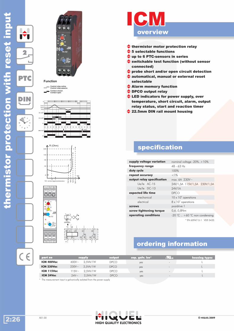
2:26
overview
ICMICM
HIGH QUALITY ELECTRONICS
2009HIQUELX01.00
specification
ordering information
therm
isto
rpro
tecti
on
wit
hre
set
input
supply voltage variation
frequency range
duty cycle
repeat accuracy
output relay specification
Ue/Ie AC-15
Ue/Ie DC-13
expected life time
operating conditions
nominal voltage -20%..+10%
48 - 63 Hz
100%
<1%
max. 6A 230V~
24V/1,5A 115V/1,5A 230V/1,5A
24V/1A
-20 .. +60 °C non condensing°C
10 x 106
operations
8 x 10⁴
operations
mechanical
electrical
DPCO
Gehäusetypenpart no supply output
ICM 24Vac
ICM 115Vac
ICM 230Vac
DPCO
DPCO
DPCO
DPCOICM 400Vac
housing types
L
L
L
L
115V~
230V~
400V~
24V~ 2,5VA/1W
2,5VA/1W
2,5VA/1W
2,5VA/1W
sup. galv. iso*
yes
yes
yes
yes
* The measurement is galvanically isolated from the power supplyinput
-
-
-
-
Control relay activeControl relay passive
Contact closedContact open
Function
U
SC-LED
OC-LED
R
MR+TST
R
1650
200
3100
A+SC
M+SC
2
DIN
thermistor motor protection relay
5 selectable functions
up to 6 PTC-sensors in series
switchable test function (without sensor
connected)
probe short and/or open circuit detection
automatical, manual or external reset
selectable
Alarm memory function
DPCO output relay
LED indicators for power supply, over
temperature, short circuit, alarm, output
relay status, start and reaction timer
22.5mm DIN rail mount housing
PTC
screws
screw tightening torque 0,6..0,8Nm
pozidrive 1
* EN 60947-5-1 VDE 0435
U
F
R1
tr
SC
OT
te
ICM230Vac
5s0s
2,5s
10min0min
5min
1
1=M2=M+SC3=A
10=TST4=A+SC
23 4
10
MR+TST
t
Y A1 A2
T2T1
24 21 22
14 11 12
12
11 21
14
R1
T1
A1 Y
22 24
R1
T2
A2
~
1...
...6
T2PTC
DIN44081
T1T1
T2
S~
4000
R (Ohm)
1330
550
250
20
-20 0
TNF: nominal triggering temperature
TN
F-2
0
TN
F-5
TN
F+
5
TN
F+
15
°C
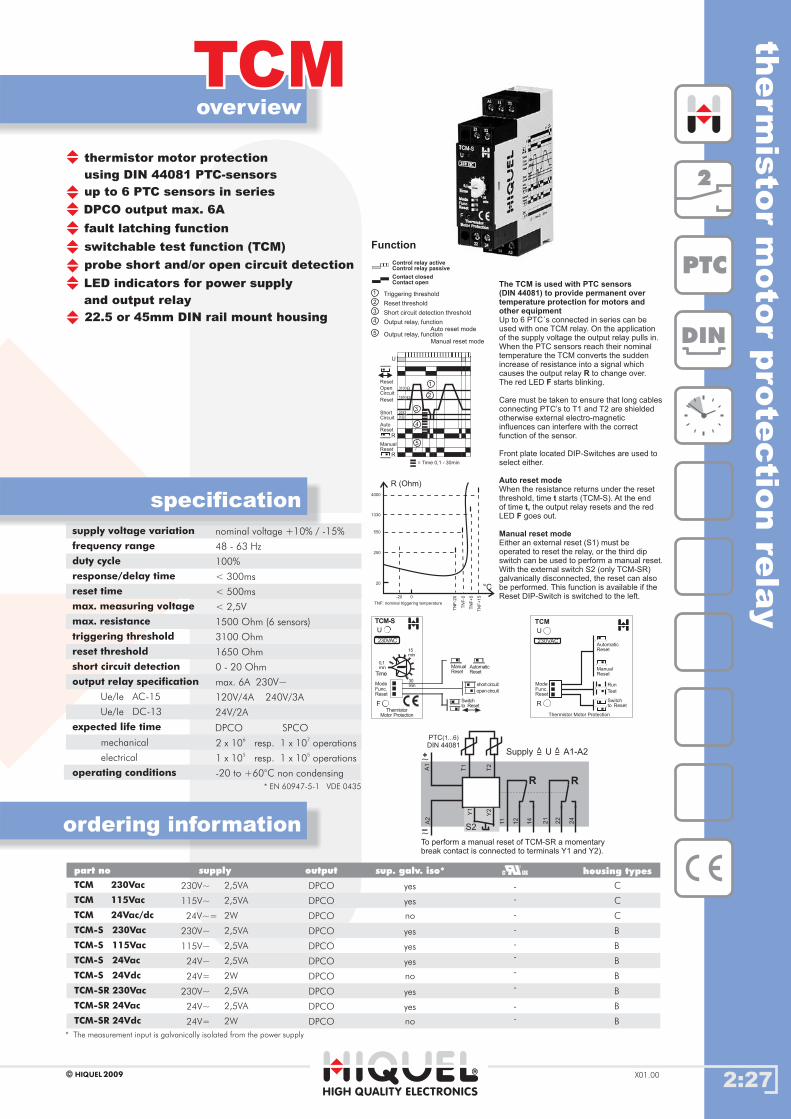
supply voltage variation
frequency range
duty cycle
response/delay time
reset time
max. measuring voltage
max. resistance
triggering threshold
reset threshold
short circuit detection
output relay specification
Ue/Ie AC-15
Ue/Ie DC-13
expected life time
nominal voltage +10% / -15%
48 - 63 Hz
100%
< 300ms
< 500ms
< 2,5V
1500 Ohm (6 sensors)
3100 Ohm
1650 Ohm
0 - 20 Ohm
max. 6A 230V~
120V/4A 240V/3A
24V/2A
mechanical
electrical
operating conditions -20 to +60°C non condensing
DPCO SPCO
2 x 10⁶
resp. 1 x 10⁷
operations
1 x 10⁵
resp. 1 x 10⁵
operations
2:27
overview
TCMTCM
HIGH QUALITY ELECTRONICS
2009HIQUEL X01.00
specification
ordering information
therm
isto
rm
oto
rpro
tectio
nre
lay
thermistor motor protection
using DIN 44081 PTC-sensors
DPCO output max. 6A
up to 6 PTC sensors in series
fault latching function
switchable test function (TCM)
probe short and/or open circuit detection
LED indicators for power supply
and output relay
22.5 or 45mm DIN rail mount housing
Gehäusetypenpart no supply output housing types
TCM 230Vac
TCM 115Vac
TCM 24Vac/dc
TCM-S 230Vac
TCM-S 115Vac
TCM-S 24Vac
TCM-S 24Vdc
TCM-SR 230Vac
TCM-SR 24Vac
TCM-SR 24Vdc
DPCO
DPCO
DPCO
DPCO
DPCO
DPCO
DPCO
DPCO
DPCO
DPCO
C
C
C
B
B
B
B
B
B
B
230V~
115V~
24V~=
230V~
115V~
24V~
24V=
230V~
24V~
24V=
2,5VA
2,5VA
2,5VA
2,5VA
2,5VA
2,5VA
2,5VA
2W
2W
2W
sup. galv. iso*
yes
yes
yes
yes
yes
yes
yes
no
no
no
* The is galvanically isolated from the power supplymeasurement input
Triggering threshold
Reset threshold
Short circuit detection threshold
Output relay, functionAuto reset mode
Output relay, functionManual reset mode
1
2
3
4
5
Control relay activeControl relay passive
Contact closedContact open
Function
4000
R (Ohm)
1330
550
250
20
-20 0
TNF: nominal triggering temperature
TN
F-2
0
TN
F-5
TN
F+
5
TN
F+
15
°C
U
R
R
AutoReset
Reset
Reset
ShortCircuit
OpenCircuit
ManualReset
0
3100
1650
20
= Time 0,1 - 30min
1
2
3
4
5
230VAC
ModeFunc.Reset
Thermistor Motor Protection
AutomaticReset
Test
Run
U
R
TCM
ManualReset
Switchto Reset
Switchto Reset
ManualReset
AutomaticReset
open circuit
short circuit
11
T1
T2
21
12 22
14 24
A2
A1
PTCDIN 44081
(1...6)
R R
Supply U A1-A2=
>
=
>
+~
-~
Y2
Y1
S2
To perform a manual reset of TCM-SR a momentarybreak contact is connected to terminals Y1 and Y2).
230VAC
ModeFunc.Reset
ThermistorMotor Protection
Time
U
F
TCM-S
0,1min
15min
30min
The TCM is used with PTC sensors(DIN 44081) to provide permanent overtemperature protection for motors andother equipment
RF
Auto reset mode
tt,
F
Manual reset mode
Up to 6 PTC´s connected in series can beused with one TCM relay. On the applicationof the supply voltage the output relay pulls in.When the PTC sensors reach their nominaltemperature the TCM converts the suddenincrease of resistance into a signal whichcauses the output relay to change over.The red LED starts blinking.
Care must be taken to ensure that long cablesconnecting PTC’s to T1 and T2 are shieldedotherwise external electro-magneticinfluences can interfere with the correctfunction of the sensor.
Front plate located DIP-Switches are used toselect either.
When the resistance returns under the resetthreshold, time starts (TCM-S). At the endof time the output relay resets and the redLED goes out.
Either an external reset (S1) must beoperated to reset the relay, or the third dipswitch can be used to perform a manual reset.With the external switch S2 (only TCM-SR)galvanically disconnected, the reset can alsobe performed. This function is available if theReset DIP-Switch is switched to the left.
2
DIN
PTC
* EN 60947-5-1 VDE 0435
-
-
-
-
-
-
-
-
-
-
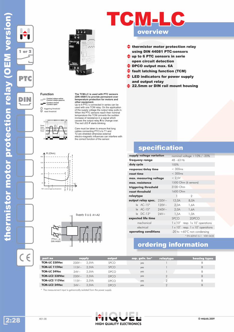
supply voltage variation
duty cycle
48 - 63 Hz
100%
< 300ms
< 300ms
< 2,5V
1500 Ohm (6 sensors)
3100 Ohm
1600 Ohm
operating conditions -20 to +60°C non condensing
output relay spec.
relaytype
Ie AC-15*
Ie AC-15*
Ie DC-13*
expected life time
12,0A 8,0A
1 2
230V~
2,0A 1,6A120V~
2,0A 1,6A
1,5A 1,0A
240V~
24V=
mechanical
electrical
1 x 10 resp.6
1x 10 operations7
1 x 10 resp.5
1 x 10 operations5
SPCO 2DPCO
TCM-LCTCM-LC
HIGH QUALITY ELECTRONICS
2009HIQUELX01.00
specification
TCM-LC 230Vac
TCM-LC2 230Vac
TCM-LC 115Vac
TCM-LC2 115Vac
TCM-LC 24Vac
TCM-LC2 24Vac
SPCO
DPCO
B
B
B
B
B
B
thermistor motor protection relay
using DIN 44081 PTC-sensors
DPCO output max. 6A
up to 6 PTC sensors in serie
open circuit detection
fault latching function (TCM)
230V~
115V~
115V~
24V~
24V~
therm
isto
rm
oto
rpro
tecti
on
rela
y(O
EM
vers
ion)
DIN
PTC
4000
R (Ohm)
1330
550
250
20
-20 0
TNF: nominal triggering temperature
TN
F-2
0
TN
F-5
TN
F+
5
TN
F+
15
°C
230V~ 2,5VA
2,5VA
2,5VA
2,5VA
2,5VA
2,5VA
ordering information
The TCM-LC is used with PTC sensors(DIN 44081) to provide permanent overtemperature protection for motors andother equipment.
RF
Up to 6 PTC´s connected in series can beused with one TCM relay. On the applicationof the supply voltage the output relay pulls in.When the PTC sensors reach their nominaltemperature the TCM converts the suddenincrease of resistance in a signal whichcauses the output relay to change over.The red LED starts blinking.
Care must be taken to ensure that longcables connecting PTC’s to T1 andT2 are shielded otherwise externalelectro-magnetic influences can interfere withthe correct function of the sensor.
Control relays activeControl relays passive
Contact closedContact open
Function
triggering threshold
reset threshold
1
2
U
R
Reset
Reset
OpenCircuit
3100
1600
1
2
11 21
12 22
14 24
A2
T1
T2
PTCDIN 44081
(1...6)
R R
U A1-A2=
>
=
>
~
A1
~
1 or 21 or 2
1
1
1
2
2
2
2:28
* EN 60947-5-1 VDE 0435
overview
22.5mm or DIN rail mount housing
LED indicators for power supply
and output relay
yes
yes
yes
yes
yes
yes
nominal voltage +10% / -20%
frequeny range
response/delay time
reset time
max. measuring voltage
max. resistance
triggering threshold
reset threshold
Supply
SPCO
DPCO
DPCO
DPCO
* The measurement is galvanically isolated from the power supplyinput
Gehäusetypenpart no supply output housing typessup. galv. iso* relaytype

2:29
overview
TCSTCS
HIGH QUALITY ELECTRONICS
2009HIQUEL X01.00
specification
ordering information
Gehäusetypenpart no supply output housing types
under speed control with
fault latching function
SPCO output max. 6A
input PNP 24Vdc, volt free contact
and 15-40Vdc
start surge delay 0.2-20s
4 selectable speed ranges
LED indicators for power supply,
relay and reaction timer
45mm DIN rail mount housing
supply voltage variation
frequency range
duty cycle
range
TCS-H
TCS
start surge delay
output relay specification
Ue/Ie AC-15
Ue/Ie DC-13
expected life time
operating conditions
nominal voltage +10% / -20%
48 - 63 Hz
100%
10-2000 Rpm
500-9000 Rpm
0 - 20 s
max. 6A 230V~
120V/5A 240V/4A
24V/3A
-20 to +60°C non condensing
mechanical
electrical
TCS 230Vac
TCS 115Vac
TCS 24Vdc
TCS-H 230Vac
TCS-H 115Vac
TCS-H 24Vdc
230V~
115V~
24V=
230V~
115V~
24V=
SPCO
SPCO
SPCO
SPCO
SPCO
SPCO
C
C
C
C
C
C
under
speed
contro
l
1
DIN
15
16
A2
A1
+24V
+24V
+24V
+24V
E2Reset
E1
E1
E1
E1
0V
15-40V
0V
0V
18
Underspeed threshold
Monitored speed
1
2
ts... Start surge delay
AutoReset
Rpm
U
0 Rpm
R
t s t 1
ManualReset
t ts s
Rpm
U
0 Rpm
R
Reset
12
Control relay activeControl relay passive
Contact closedContact open
Function
PNP
rpm
+~
-~
R
Supply U A1-A2=
>
=
>
2,5VA
2,5VA
2,5VA
2,5VA
2W
2W
sup. galv. iso*
yes
yes
yes
yes
no
no
* The measurement is galvanically isolated from the power supplyinput
DPCO SPCO
2 x 10⁶
resp. 1 x 10⁷
operations
1 x 10⁵
resp. 1 x 10⁵
operations
Control relay to monitorunder speed
ts
Auto Reset
Manual Reset
ts
On application of the supply voltagethe output relay energisesand the timing period starts.The TCS monitors the time betweenthe leading edge ofsuccessive input pulses. Whenthe timing period between the pulsesexceeds the set value,the output relay drops out.
When the timing period between thepulses returns to the acceptable rangefor three successive pulses the outputrelay resets.
The output relay resets whenterminals +24 and E2 are connected.After breaking the connection timestarts.
230VAC
Under Speed Control
Manual Reset
10-500 Rpm
t
500-1000 Rpm
s
1000-1500 Rpm
1500-2000 Rpm
U
R
Imp.
TCS
Auto Reset
0s
20s
10s
0%
100%
230V AC
Under Speed Control
Manual Reset
500-1500 Rpm
t
1500-3000 Rpm
s
3000-6000 Rpm
6000-9000 Rpm
U
R
Imp.
TCS-H
Auto Reset
0s
20s
10s
0%
100%
screws
screw tightening torque 0,6..0,8Nm
pozidrive 1
* EN 60947-5-1 VDE 0435
-
-
-
-
-
-

2:30
overview
DGRDGR
HIGH QUALITY ELECTRONICS
2009HIQUELX01.00
specification
ordering information
Gehäusetypenpart no supply output
DGR 230Vac
DGR 24Vdc 24V=
230V~ SPCO
SPCO
housing types
C
B
speed control/PLC watchdog relay
SPCO output max. 6A
6 selectable time ranges
LED indicators for power supply
and output relay
22.5 or 45mm DIN rail mount housing
supply voltage variation
frequency range
max delay time
max input frequency
output relay specification
Ue/Ie AC-15
Ue/Ie DC-13
expected life time
nominal voltage +10% / -15%
48 - 63 Hz
100% of the selected time range
10Hz or 600 Rpm
max. 6A 230V~
120V/5A 240V/4A
24V/4A
mechanical
electrical
operating conditions -20 to +60°C non condensing
speed
contr
ol/P
LC
watc
hdog
rela
y
1
DIN1
5
16
A2
A1
+24V
E1
0V
18
PNP
0,1s-1,0s
1,0s-10s
0,1min-1,0min
1,0min-10min
0,1h-1,0h
1,0h-10h
The required delay time within the range selected is set using thepotentiometer on the front plate
Time ranges
E1
R
t t
U
Control relay active
Control relay passive
Contact closed
Contact open
Function
Supply U A1-A2=
>
=
>
+~
-~
R
rpm
2VA
1W
sup. galv. iso*
yes
no
* The measurement input is galvanically isolated from the power supply
DPCO SPCO
2 x 10⁶
resp. 1 x 10⁷
operations
1 x 10⁵
resp. 1 x 10⁵
operations
A Control relay to monitor changing impulses on a sensor
t
After applying the supply voltage the relay waits to see the leadingedge of an input pulse.When the pulse is detected the output relay energises. When thereare no more pulses measured during time , the output relay dropsout.
screws
screw tightening torque 0,6..0,8Nm
pozidrive 1
* EN 60947-5-1 VDE 0435
-
-
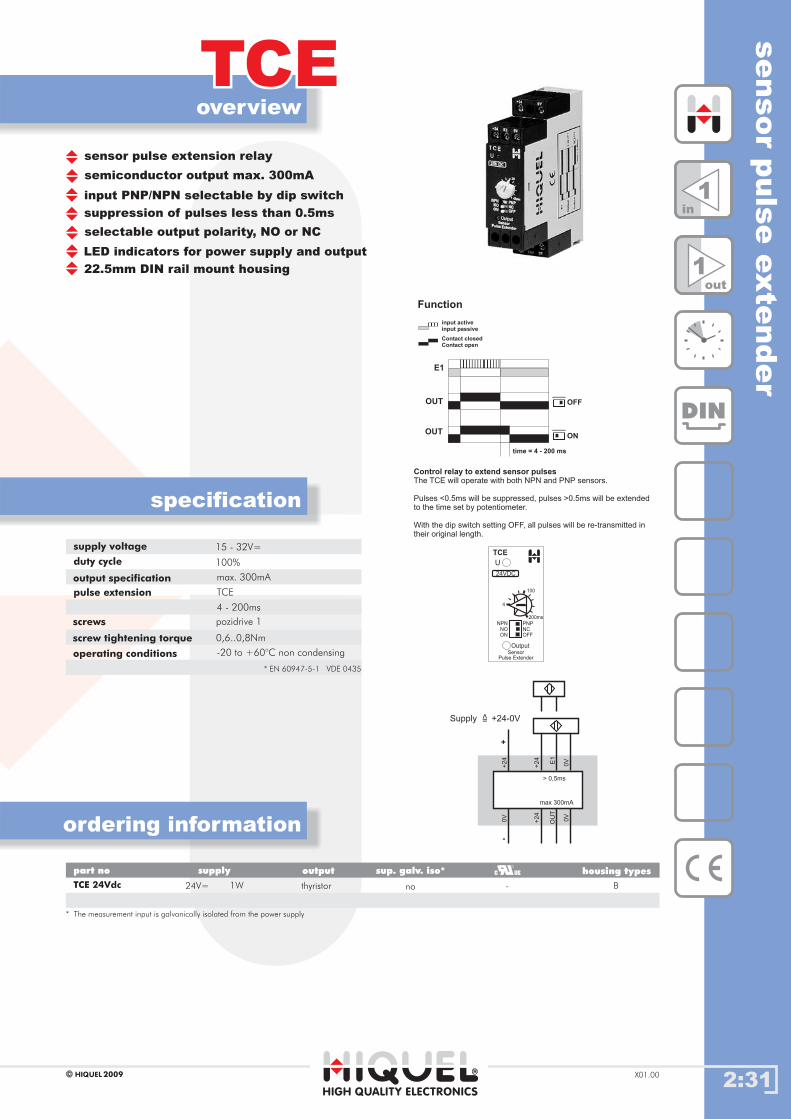
2:31
overview
TCETCE
HIGH QUALITY ELECTRONICS
2009HIQUEL X01.00
specification
ordering information
Gehäusetypenpart no supply output
TCE 24Vdc thyristor
housing types
B
sensor pulse extension relay
semiconductor output max. 300mA
input PNP/NPN selectable by dip switch
suppression of pulses less than 0.5ms
selectable output polarity, NO or NC
LED indicators for power supply and output
22.5mm DIN rail mount housing
supply voltage
duty cycle
output specification
pulse extension
operating conditions
15 - 32V=
100%
max. 300mA
TCE
4 - 200ms
-20 to +60°C non condensing
sensor
puls
eexte
nder
DIN
OU
TE
1
0V 0V
0V
+2
4
+2
4+
24
> 0,5ms
max 300mA
OUT
E1
OFF
ONOUT
time = 4 - 200 ms
Control relay to extend sensor pulsesThe TCE will operate with both NPN and PNP sensors.
Pulses <0.5ms will be suppressed, pulses >0.5ms will be extendedto the time set by potentiometer.
With the dip switch setting OFF, all pulses will be re-transmitted intheir original length.
input activeinput passive
Contact closedContact open
Function
1in
1out
+
-
Supply +24-0V=
>
24V= 1W
sup. galv. iso*
* The measurement is galvanically isolated from the power supplyinput
no
24VDC
U
Output
TCE
4
100
200ms
NPN
OFFNC
ONNO
PNP
SensorPulse Extender
screws
screw tightening torque 0,6..0,8Nm
pozidrive 1
* EN 60947-5-1 VDE 0435
-
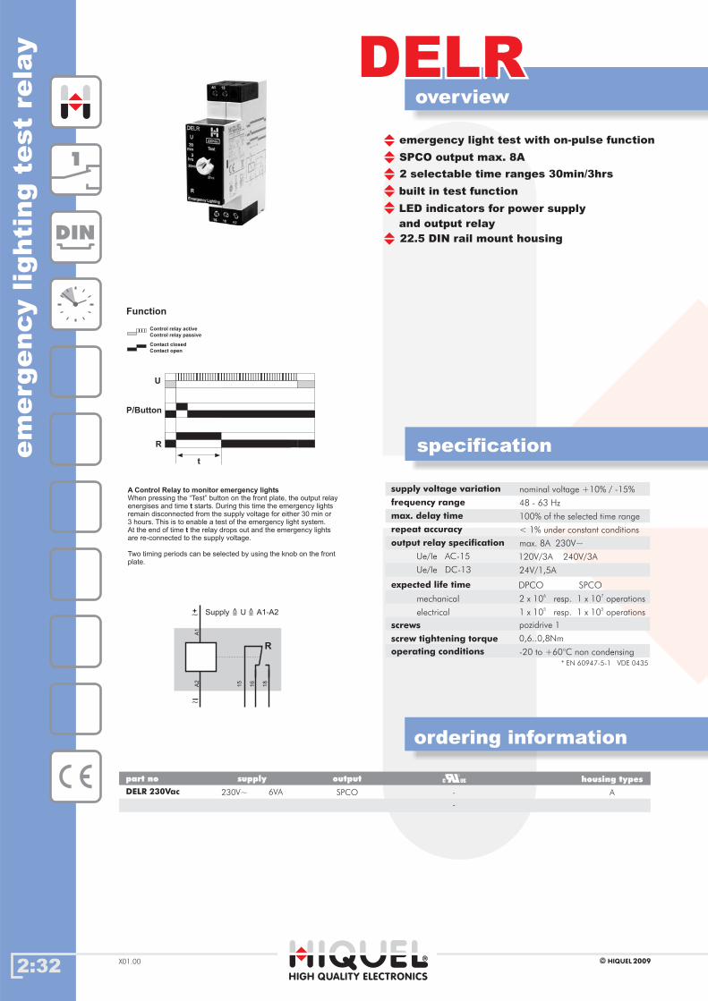
2:32
overview
DELRDELR
HIGH QUALITY ELECTRONICS
2009HIQUELX01.00
specification
ordering information
Gehäusetypenpart no supply output
DELR 230Vac 230V~ 6VA SPCO
housing types
A
emergency light test with on-pulse function
SPCO output max. 8A
2 selectable time ranges 30min/3hrs
built in test function
LED indicators for power supply
and output relay
22.5 DIN rail mount housing
supply voltage variation
frequency range
max. delay time
repeat accuracy
output relay specification
Ue/Ie AC-15
Ue/Ie DC-13
expected life time
nominal voltage +10% / -15%
48 - 63 Hz
100% of the selected time range
< 1% under constant conditions
max. 8A 230V~
120V/3A 240V/3A
24V/1,5A
mechanical
electrical
operating conditions -20 to +60°C non condensing
em
erg
ency
lighti
ng
test
rela
y
1
DIN
U
R
t
P/Button
Control relay active
Control relay passive
Contact closed
Contact open
Function
15
16
A2
A1
18
+~
-~
Supply U A1-A2=
>
=
>
R
DPCO SPCO
2 x 10⁶
resp. 1 x 10⁷
operations
1 x 10⁵
resp. 1 x 10⁵
operations
A Control Relay to monitor emergency lights
t
t
When pressing the “Test” button on the front plate, the output relayenergises and time starts. During this time the emergency lightsremain disconnected from the supply voltage for either 30 min or3 hours. This is to enable a test of the emergency light system.At the end of time the relay drops out and the emergency lightsare re-connected to the supply voltage.
Two timing periods can be selected by using the knob on the frontplate.
screws
screw tightening torque 0,6..0,8Nm
pozidrive 1
* EN 60947-5-1 VDE 0435
-
-
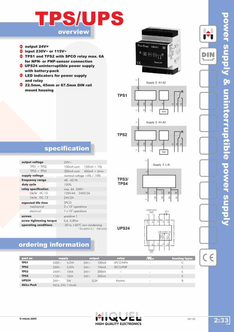
2:33
overview
TPS/UPSTPS/UPS
HIGH QUALITY ELECTRONICS
2009HIQUEL X01.00
specification
ordering information
Gehäusetypenpart no supply output housing types
output 24V=
input 230V~ or 115V~
TPS1 and TPS2 with SPCO relay max. 6A
for NPN- or PNP-sensor connection
LED indicators for power supply
and relay
UPS24 uninterruptible power supply
with battery-pack
22.5mm, 45mm or 67.5mm DIN rail
mount housing
output voltage
TPS1 + TPS2
TPS3 + TPS4
supply voltage
frequency range
duty cycle
24V=
100mA cont.
300mA cont.
150mA < 10s
400mA < 5min
nominal voltage +6% / -10%
48 - 63 Hz
100%
relay specification
Ue/Ie AC-15
Ue/Ie DC-13
expected life time
operating conditions
max. 6A 230V~
120V/4A 240V/3A
24V/2A
mechanical
-20 to +60°C non condensing
electrical
2 x 10⁷
operations
1 x 10⁵
operations
SPCO
TPS1
TPS2
TPS3
TPS4
UPS24
Akku-Pack
230V~
230V~
230V~
115V~
24V=
NiCd, 24V, 110mAh
3,2VA
3,2VA
10VA
10VA
2W
C
C
E
E
B
24V=
24V=
24V=
24V=
0,2A
100mA
100mA
300mA
300mA
relay
SPCO/NPN
SPCO/PNP
-
-
thyristor
pow
er
supply
&unin
terruptib
lepow
er
supply
DIN
N ML+
ML+
L
+2
4
+2
4
0V
0V
TPS3/TPS4
~
~
Supply L-N=>
15
16
A2
0V
A1
+2
4 E
18
NPN
TPS1
+
~
~ -
Supply A1-A2=
>
R
15
16
A2
0V
A1
+2
4
E 18
TPS2
PNP+
~
~ -
Supply A1-A2=
>
R
UPS24LOW VOLTAGE ON
POWER
SUPPLY
14
C+
24
ACCU
M-
L+OUT
LOAD
A+B1
A-
ACCU
M-
L+IN
+
POWERSUPPLY
24VDC
+ -
screws
screw tightening torque 0,6..0,8Nm
pozidrive 1
* EN 60947-5-1 VDE 0435
-
-
-
-
-
-