WORKSHOP MANUAL - Wanderlodge Gurus - The …wanderlodgegurus.com/database/Theory/ISRI 6800 Workshop...
26
ISRI 6800/337.(EDI. JAN.2000) REV.1 DRIVER SEATS ISRI 6800/337 WORKSHOP MANUAL
-
Upload
truongthien -
Category
Documents
-
view
232 -
download
1
Transcript of WORKSHOP MANUAL - Wanderlodge Gurus - The …wanderlodgegurus.com/database/Theory/ISRI 6800 Workshop...
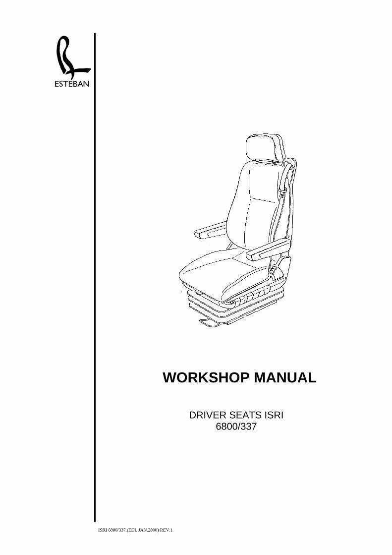
ISRI 6800/337.(EDI. JAN.2000) REV.1
DRIVER SEATS ISRI
6800/337
WORKSHOP MANUAL

ASIENTOS ESTEBAN
ISRI 6800/337 0.- INDEX
INDEX
1.- IMPORTANT NOTES 1.1.0
2.- CONTROL ELEMENTS 2.1.0 3.- SERIES NUMBER 3.1.0 4.- REPAIR MODULES (Before any repair operation please read also Chapter 1)
Complete seat 4.1.0 Cushion/sliding guide 4.1.0 Rail 4.1.0 Bellows 4.1.0 Lateral coatings 4.1.0 Front coatings 4.1.0 Rear coatings 4.2.0 Heating switch 4.3.0 LWS valves 4.3.0 Headrest 4.3.0 Backrest 4.4.0 Backrest coating 4.4.0 Three-point belt 4.5.0 Backrest cover/cushion cover 4.5.0 Air pillow for lumbar support 4.5.0 Heating elements 4.6.0 Backrest locking 4.6.0 Height adjusting valve 4.7.0 Seat lowering valve 4.7.0 Height adjustment lever 4.8.0 Tilting adjustment lever 4.8.0 Seat lowering lever 4.9.0 Lever for adjusting the cushion deepness 4.9.0 Support arm / tilting adjustment zipper 4.10.0 Selective valve 4.10.0 Level regulation valve 4.10.0 Adjusting cylinder 4.10.0 Control disc unit 4.10.0 Vertical buffer 4.11.0 Crash buffer adjustment 4.11.0 Pneumatic spring 4.11.0 Air tubes repair kit 4.11.0 Residual pressure valve 4.12.0 Complementary air deposit 4.12.0 Tilting system 4.13.0 Rotating device 4.14.0
5.- TROUBLESHOOTING; PNEUMATICS 5.1.0
6.- PNEUMATIC SCHEME 6.1.0 7.- REPAIR TIMES 7.1.0
ISRI 6800/337.(EDI. JAN .2000) REV. 1 0.1.0
ASIENTOS ESTEBAN
ISRI 6800/337 1.- IMPORTANT HINTS
1.- IMPORTANT HINTS: • Seat repair has to be carried out by competent staff only. • The presentation in this booklet shows as a rule the left seat resp. The left seat side.
On the right seat resp. The right seat side the repair will be carried out. • The description in the chapter explains the removal of sundry seat components. The installation
of these seat components generally happens in reverse sequence. • Fastening parts for hoses and cables (e.g. cable binder), as well as hose clamps will not be
mentioned in detail. Nevertheless it is necessary after repairs to put the laying of hoses and cables, as well as their fastening and securing attachment (coloured marking) when mounting the hoses.
• Hoses and Bowden cables must not be creased. • At transport and storage pay attention to that the seat will be put down only flat onto the guide
rails. Airlines must not be creased in doing so.
• Due to safety reasons pay attention to the correct positioning and to the observance of the
tightening torques of the fixing screw when exchanging points component parts, which lie within the flux line of the belt anchorage points.
Tightening torques: M 8 = 20 Nm + 5 Nm
7/16”UNF-2B = 30 Nm + 5 Nm • Roll off the belt from the roller, please not that the roller has to be positioned in assembling
position corresponding mounted seat. • After each repair a functional test and, if pneumatic parts are involved, a leak test has to be
effected. • Backrest in forward folded position must not be used as ascent help.
ISRI 6800/337.(EDI.JAN.2000) REV.1 1.1.0
ASIENTOS ESTEBAN
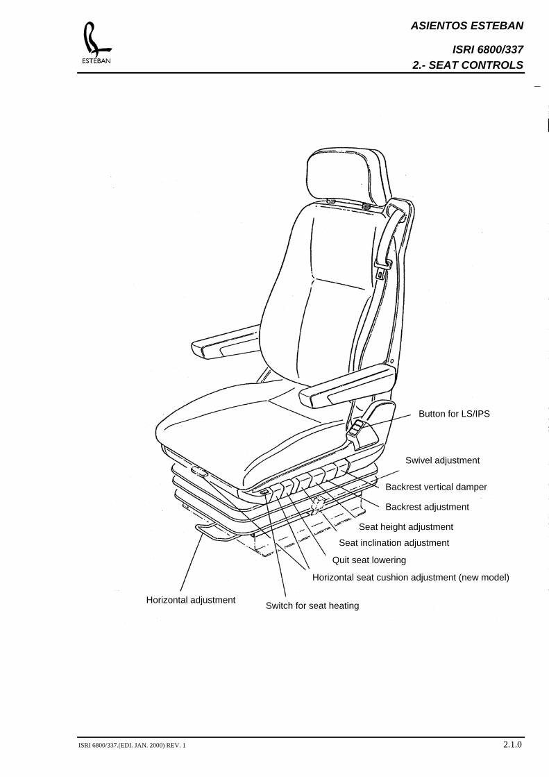
ISRI 6800/337 2.- SEAT CONTROLS
Switch for seat hHorizontal adjustment
Horiz
Q
Seat height adjustment
Backrest adjustment
Backrest vertical damper
Swivel adjustment
Button for LS/IPS
ISRI 6800/337.(EDI. JAN. 2000) REV. 1
Seat inclination adjustment
eating
ontal seat cushion adjustment (new model)
uit seat lowering
2.1.0
ASIENTOS ESTEBAN
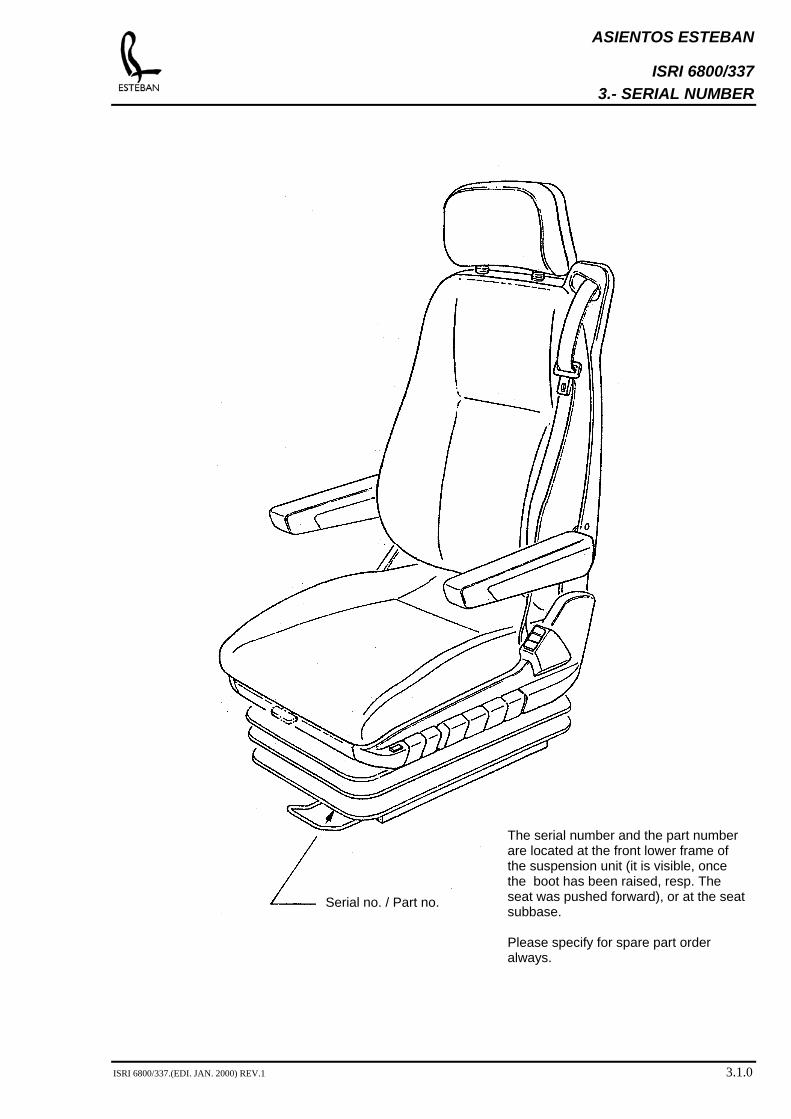
ISRI 6800/337 3.- SERIAL NUMBER
The serial number and the part number are located at the front lower frame of the suspension unit (it is visible, once the boot has been raised, resp. The seat was pushed forward), or at the seat subbase. Please specify for spare part order always.
Serial no. / Part no.
ISRI 6800/337.(EDI. JAN. 2000) REV.1 3.1.0
ASIENTOS ESTEBAN
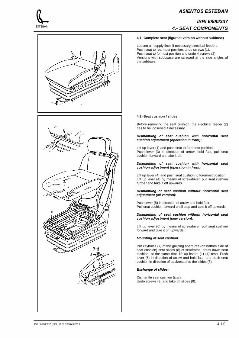
ISRI 6800/337 4.- SEAT COMPONENTS
4.1.-Complete seat (figured: version without subbase) Loosen air supply lines if necessary electrical feeders. Push seat to rearmost position, undo screws (1). Push seat to formost position and undo 4 screws (2). Versions with subbsase are screwed at the side angles of the subbase. 4.2.-Seat cushion / slides Before removing the seat cushion, the electrical feeder (2) has to be loosened if necessary. Dismantling of seat cushion with horizontal seat cushion adjustment (operation in front): Lift up lever (1) and push seat to foremost position. Push lever (3) in direction of arrow, hold fast, pull seat cushion forward ant take it off. Dismantling of seat cushion with horizontal seat cushion adjustment (operation in front): Lift up lever (4) and push seat cushion to foremost position. Lift up lever (4) by means of screwdriver, pull seat cushion further and take it off upwards. Dismantling of seat cushion without horizontal seat adjustment (all version): Push lever (5) in direction of arrow and hold fast. Pull seat cushion forward untill stop and take it off upwards. Dismantling of seat cushion without horizontal seat cushion adjustment (new version): Lift up lever (6) by means of screwdriver, pull seat cushion forward and take it off upwards. Mounting of seat cushion: Put keyholes (7) of the guilding apertures (on bottom side of seat cushion) onto slides (8) of seatframe, press down seat cushion, at the same time lift up levers (1) (4) resp. Push lever (5) in direction of arrow and hold fast, and push seat cushion in direction of backrest onto the slides (8). Exchange of slides: Dismantle seat cushion (s.a.). Undo screws (9) and take off slides (8).
ISRI 6800/337.(EDI. JAN. 2000) REV.1 4.1.0
ASIENTOS ESTEBAN
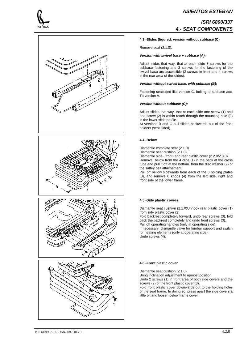
ISRI 6800/337 4.- SEAT COMPONENTS
4.3.-Slides (figured: version without subbase (C) Remove seat (2.1.0). Version with swivel base + subbase (A): Adjust slides that way, that at each slide 3 screws for the subbase fastening and 3 screws for the fastening of the swivel base are accessible (2 screws in front and 4 screws in the rear area of the slides). Version without swivel base, with subbase (B): Fastening seatsided like version C, bolting to subbase acc. To version A. Version without subbase (C): Adjust slides that way, that at each slide one screw (1) and one screw (2) is within reach through the mounting hole (3) in the lower slide profile. At versions B and C pull slides backwards out of the front holders (seat sided). 4.4.-Below Dismantle complete seat (2.1.0). Dismantle seat cushion (2.1.0). Dismantle side-, front- and rear plastic cover (2.2.0/2.3.0). Remove below from the 4 clips (1) in the back at the cross tube and pull it off at the bottom from the disc washer (2) of the saftey belt attachement. Pull off bellow sidewards from each of the 3 holding plates (3), and remove 6 knobs (4) from the left side, right and front side of the lower frame. 4.5.-Side plastic covers Dismantle seat cushion (2.1.0)Unhook rear plastic cover (1) from side plastic cover (2). Fold backrest completely forward, undo rear screws (3), fold back the backrest completely and undo front screws (3). Pull off operating handles (only at operating side). If necessary, dismantle valve for lumbar support and switch for heating elements (only at operating side). Undo screws (4). 4.6.-Front plastic cover Dismantle seat cushion (2.1.0). Bring inclination adjustment to upmost position. Undo 2 screws (1) in front area of both side covers and the screws (2) of the front plastic cover (3). Fold front plastic cover downwards out to the holding holes of the seat frame. In doing so, press apart the side covers a little bit and loosen below frame cover
ISRI 6800/337.(EDI. JAN. 2000) REV.1 4.2.0
ASIENTOS ESTEBAN
ISRI 6800/337 4.- SEAT COMPONENTS
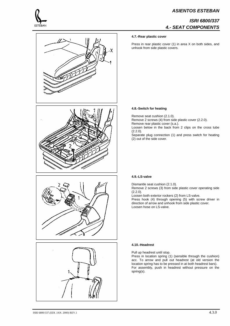
4.7.-Rear plastic cover Press in rear plastic cover (1) in area X on both sides, and unhook from side plastic covers. 4.8.-Switch for heating Remove seat cushion (2.1.0). Remove 2 screws (4) from side plastic cover (2.2.0). Remove rear plastic cover (s.a.). Loosen below in the back from 2 clips on the cross tube (2.2.0). Separate plug connection (1) and press switch for heating (2) out of the side cover. 4.9.-LS-valve Dismantle seat cushion (2.1.0). Remove 2 screws (3) from side plastic cover operating side (2.2.0). Loosen both exterior rockers (2) from LS-valve. Press hook (4) through opening (5) with screw driver in direction of arrow and unhook from side plastic cover. Loosen hose on LS-valve. 4.10.-Headrest Pull up headrest until stop. Press in location spring (1) (sensible through the cushion) acc. To arrow and pull out headrest (at old version the location spring has to be pressed in at both headrest bars). For assembly, push in headrest without pressure on the spring(s).
ISRI 6800/337.(EDI. JAN. 2000) REV.1 4.3.0

ASIENTOS ESTEBAN
ISRI 6800/337 4.- SEAT COMPONENTS
4.11.-Backrest Remove seat cushion (2.1.0). Remove backrest plastic cover (s.b.). If necessary, separate electr. Feeder and airlines to backrest. Separate cable binder (1) (2) and remove fastening (3). Unscrew axle bolt (4) and lever the square bracket of the backrest out of the backrest of the seatframe. 4.12.-Backrest plastic cover Loosen rear plastic cover from side plastic cover (2.3.0). Fold backrest completely forward, undo rear screws (3), fold backrest completely and undo front screws (3). Remove headrest and if necessary armrests. Undo screw (1) of belt attachment (when exchanging the textile cover keep it mounted) and undo screws (2) of backrest plastic cover (4). Pull out the belt a little bit, loosen backrest plastic cover at the bottom from the square cushion and press upwards out of the belt reserving guide (5). At exchange of belt or backrest textile cover, the screw (6) of the belt reserving guide (5) has to be loosened in addition. Push belt along with belt tongue and anchor plate through aperture (7) of cover.
ISRI 6800/337.(EDI. JAN. 2000) REV.1 4.4.0
ASIENTOS ESTEBAN
ISRI 6800/337 4.- SEAT COMPONENTS
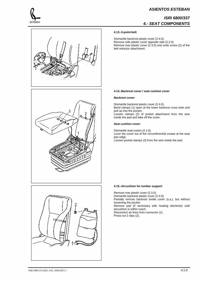
4.13.-3-point-belt Dismantle backrest plastic cover (2.4.0). Remove side plastic cover opposite side (2.2.0). Remove rear plastic cover (2.3.0) and undo screw (2) of the belt retractor attachment. 4.14.-Backrest cover / seat cushion cover Backrest cover: Dismantle backrest plastic cover (2.4.0). Bend clamps (1) open at the lower backrest cross tube and pull up into the pocket. Loosen clamps (2) of pocket attachment from the wire inside the pad and take off the cover. Seat cushion cover: Dismantle seat cusion (2.1.0). Lever the cover out of the circumferential crease at the seat pan edge. Loosen pocket clamps (3) from the wire inside the pad. 4.15.-Aircushion for lumbar support Remove rear plastic cover (2.3.0). Dismantle backrest plastic cover (2.4.0). Partially remove backrest textile cover (s.a.), but without loosening the pocket. Remove pad (if necessary with heating elements) until aircushion is within reach. Disconnect air lines from connector (1). Press out 2 clips (2).
ISRI 6800/337.(EDI. JAN. 2000) REV.1 4.5.0
ASIENTOS ESTEBAN
ISRI 6800/337 4.- SEAT COMPONENTS
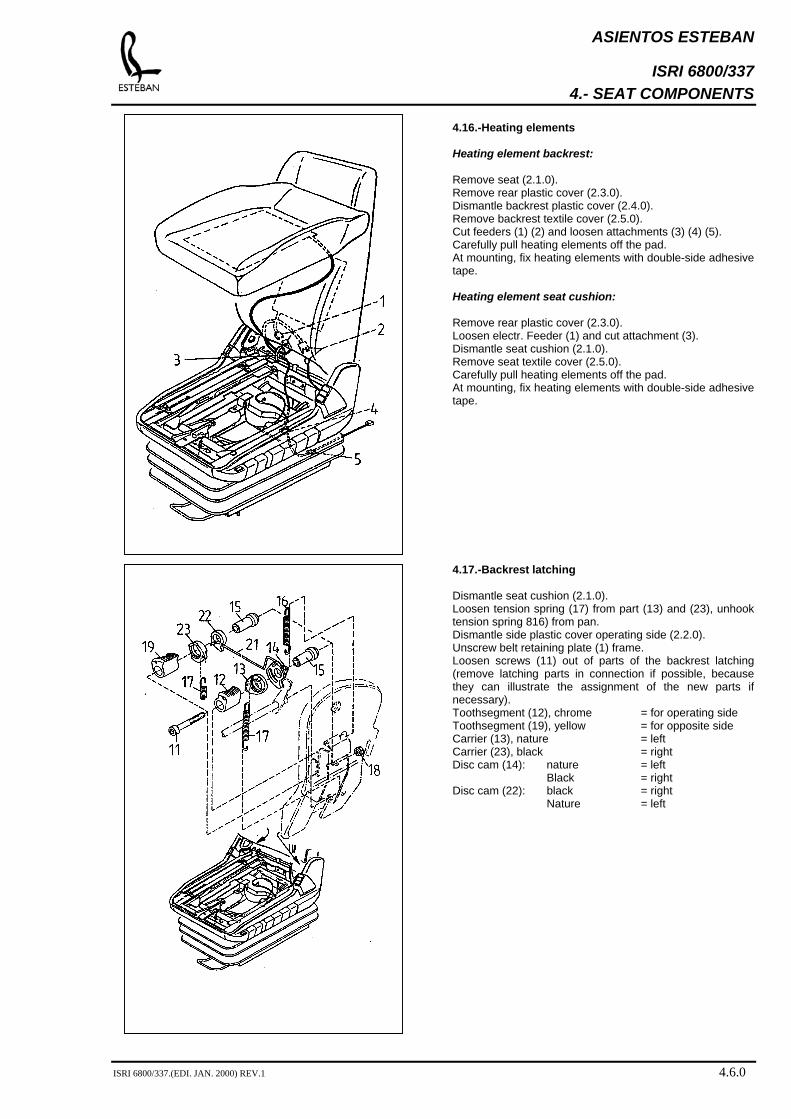
4.16.-Heating elements Heating element backrest: Remove seat (2.1.0). Remove rear plastic cover (2.3.0). Dismantle backrest plastic cover (2.4.0). Remove backrest textile cover (2.5.0). Cut feeders (1) (2) and loosen attachments (3) (4) (5). Carefully pull heating elements off the pad. At mounting, fix heating elements with double-side adhesive tape. Heating element seat cushion: Remove rear plastic cover (2.3.0). Loosen electr. Feeder (1) and cut attachment (3). Dismantle seat cushion (2.1.0). Remove seat textile cover (2.5.0). Carefully pull heating elements off the pad. At mounting, fix heating elements with double-side adhesive tape. 4.17.-Backrest latching Dismantle seat cushion (2.1.0). Loosen tension spring (17) from part (13) and (23), unhook tension spring 816) from pan. Dismantle side plastic cover operating side (2.2.0). Unscrew belt retaining plate (1) frame. Loosen screws (11) out of parts of the backrest latching (remove latching parts in connection if possible, because they can illustrate the assignment of the new parts if necessary). Toothsegment (12), chrome = for operating side Toothsegment (19), yellow = for opposite side Carrier (13), nature = left Carrier (23), black = right Disc cam (14): nature = left
Black = right Disc cam (22): black = right
Nature = left
ISRI 6800/337.(EDI. JAN. 2000) REV.1 4.6.0
ASIENTOS ESTEBAN
ISRI 6800/337 4.- SEAT COMPONENTS
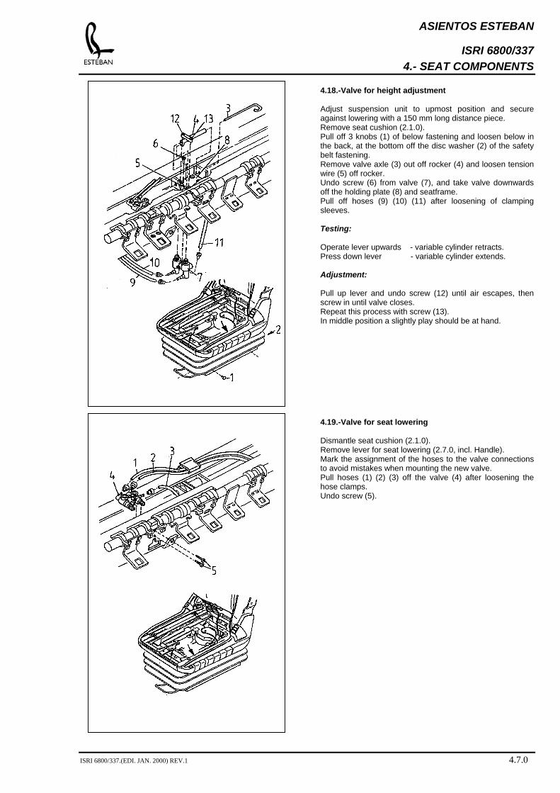
4.18.-Valve for height adjustment Adjust suspension unit to upmost position and secure against lowering with a 150 mm long distance piece. Remove seat cushion (2.1.0). Pull off 3 knobs (1) of below fastening and loosen below in the back, at the bottom off the disc washer (2) of the safety belt fastening. Remove valve axle (3) out off rocker (4) and loosen tension wire (5) off rocker. Undo screw (6) from valve (7), and take valve downwards off the holding plate (8) and seatframe. Pull off hoses (9) (10) (11) after loosening of clamping sleeves. Testing: Operate lever upwards - variable cylinder retracts. Press down lever - variable cylinder extends. Adjustment: Pull up lever and undo screw (12) until air escapes, then screw in until valve closes. Repeat this process with screw (13). In middle position a slightly play should be at hand. 4.19.-Valve for seat lowering Dismantle seat cushion (2.1.0). Remove lever for seat lowering (2.7.0, incl. Handle). Mark the assignment of the hoses to the valve connections to avoid mistakes when mounting the new valve. Pull hoses (1) (2) (3) off the valve (4) after loosening the hose clamps. Undo screw (5).
ISRI 6800/337.(EDI. JAN. 2000) REV.1 4.7.0
ASIENTOS ESTEBAN
ISRI 6800/337 4.- SEAT COMPONENTS
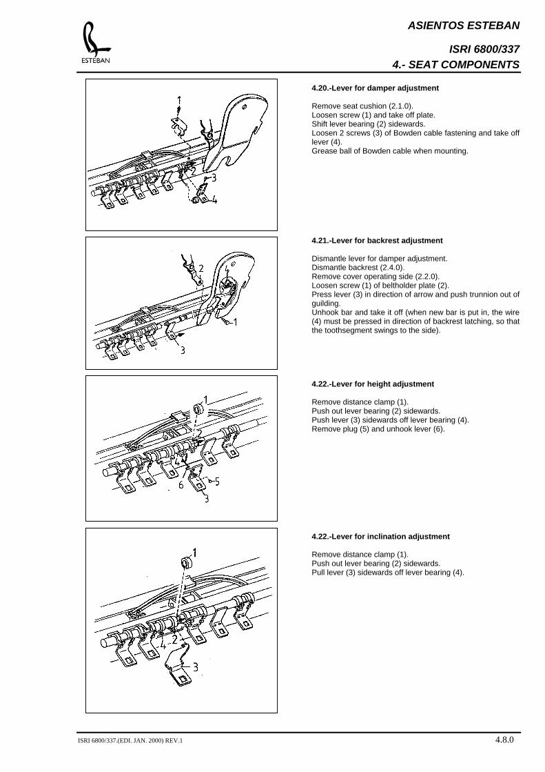
4.20.-Lever for damper adjustment Remove seat cushion (2.1.0). Loosen screw (1) and take off plate. Shift lever bearing (2) sidewards. Loosen 2 screws (3) of Bowden cable fastening and take off lever (4). Grease ball of Bowden cable when mounting. 4.21.-Lever for backrest adjustment Dismantle lever for damper adjustment. Dismantle backrest (2.4.0). Remove cover operating side (2.2.0). Loosen screw (1) of beltholder plate (2). Press lever (3) in direction of arrow and push trunnion out of guilding. Unhook bar and take it off (when new bar is put in, the wire (4) must be pressed in direction of backrest latching, so that the toothsegment swings to the side). 4.22.-Lever for height adjustment Remove distance clamp (1). Push out lever bearing (2) sidewards. Push lever (3) sidewards off lever bearing (4). Remove plug (5) and unhook lever (6). 4.22.-Lever for inclination adjustment Remove distance clamp (1). Push out lever bearing (2) sidewards. Pull lever (3) sidewards off lever bearing (4).
ISRI 6800/337.(EDI. JAN. 2000) REV.1 4.8.0

ASIENTOS ESTEBAN
ISRI 6800/337 4.- SEAT COMPONENTS
4.23.-Lever for lowering Dismantle seat cushion (2.1.0). Remove distance clamp (1). Push out lever bearing (2) sidewards and distort that way, that lever (3) can be pulled out of the lever bearing (4). If necessary, change stop (5) and latch slide block (6). 4.24.-Lever for horizontal seat cushion adjustment Dismantle seat cushion (2.1.0). Remove distance clamp (1). Push lever bearing (2) sidewards off the lever (3). Push lever (3) off lever bearing (4). Unhook spring (5) off the profile of seatframe (6). Loosen adjustment screw (7) from transmission rod. Take lever (3) out of the seatframe and unhook spring (5). Notice: At mounting of new lever, the adjusting screw (7) has to be adjusted that way, that the lever for the horizontal seat cushion adjustment latches clearly in and out.. 4.25.-Bracket / toothbar for inclination adjustment Bracket: Dismantle seat cushion (2.1.0). Adjust height- and slope adjustment in upmost position and secure seatframe against lowering. Unhook tension spring (1) at the toothbar (2) and tension springs (3) at the latch bolts (4) of the bracket (5), left side and right side. Dismantle retaining washer (6) and remove toothbar (2). Unscrew nuts (7) and remove toothbar (2). Undo 4 screws (9), shift the bracket within the elongated holes of the seatframe that way, that one latch bolt (4) can be levered out through aperture (10) and subsequently be pressed downwards. Pull opposite bracket-latch bolts out off the corresponding aperture. Toothbar (2): Dismantle seat cushion (2.1.0). Secure suspension unit with a distance piece in upmost position and loosen below at time in the lower area of the operating and front side. Lock seat by means of incllination adjustment in highest slope position. Unhook spring (1) and dismantle retaining washer (6). Press out bearing bolt (11) towards seat interior.
ISRI 6800/337.(EDI. JAN. 2000) REV.1 4.9.0
ASIENTOS ESTEBAN
ISRI 6800/337 4.- SEAT COMPONENTS
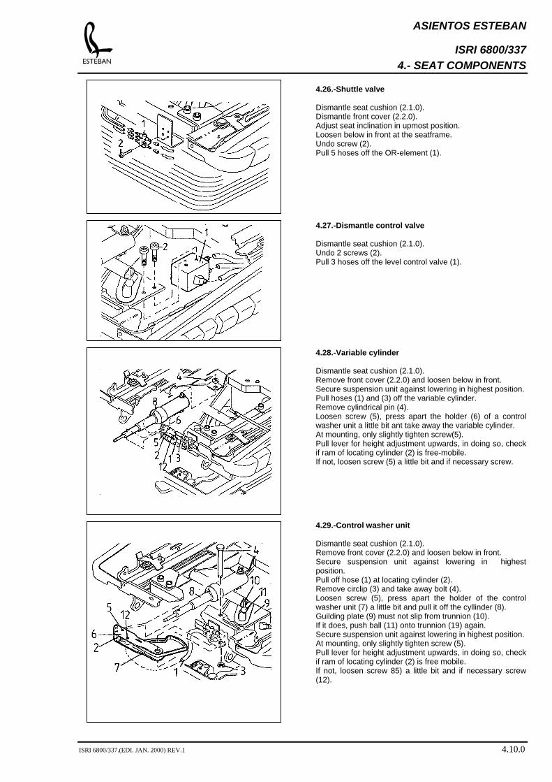
4.26.-Shuttle valve Dismantle seat cushion (2.1.0). Dismantle front cover (2.2.0). Adjust seat inclination in upmost position. Loosen below in front at the seatframe. Undo screw (2). Pull 5 hoses off the OR-element (1). 4.27.-Dismantle control valve Dismantle seat cushion (2.1.0). Undo 2 screws (2). Pull 3 hoses off the level control valve (1). 4.28.-Variable cylinder Dismantle seat cushion (2.1.0). Remove front cover (2.2.0) and loosen below in front. Secure suspension unit against lowering in highest position. Pull hoses (1) and (3) off the variable cylinder. Remove cylindrical pin (4). Loosen screw (5), press apart the holder (6) of a control washer unit a little bit ant take away the variable cylinder. At mounting, only slightly tighten screw(5). Pull lever for height adjustment upwards, in doing so, check if ram of locating cylinder (2) is free-mobile. If not, loosen screw (5) a little bit and if necessary screw. 4.29.-Control washer unit Dismantle seat cushion (2.1.0). Remove front cover (2.2.0) and loosen below in front. Secure suspension unit against lowering in highest position. Pull off hose (1) at locating cylinder (2). Remove circlip (3) and take away bolt (4). Loosen screw (5), press apart the holder of the control washer unit (7) a little bit and pull it off the cyllinder (8). Guilding plate (9) must not slip from trunnion (10). If it does, push ball (11) onto trunnion (19) again. Secure suspension unit against lowering in highest position. At mounting, only slightly tighten screw (5). Pull lever for height adjustment upwards, in doing so, check if ram of locating cylinder (2) is free mobile. If not, loosen screw 85) a little bit and if necessary screw (12).
ISRI 6800/337.(EDI. JAN. 2000) REV.1 4.10.0
ASIENTOS ESTEBAN
ISRI 6800/337 4.- SEAT COMPONENTS
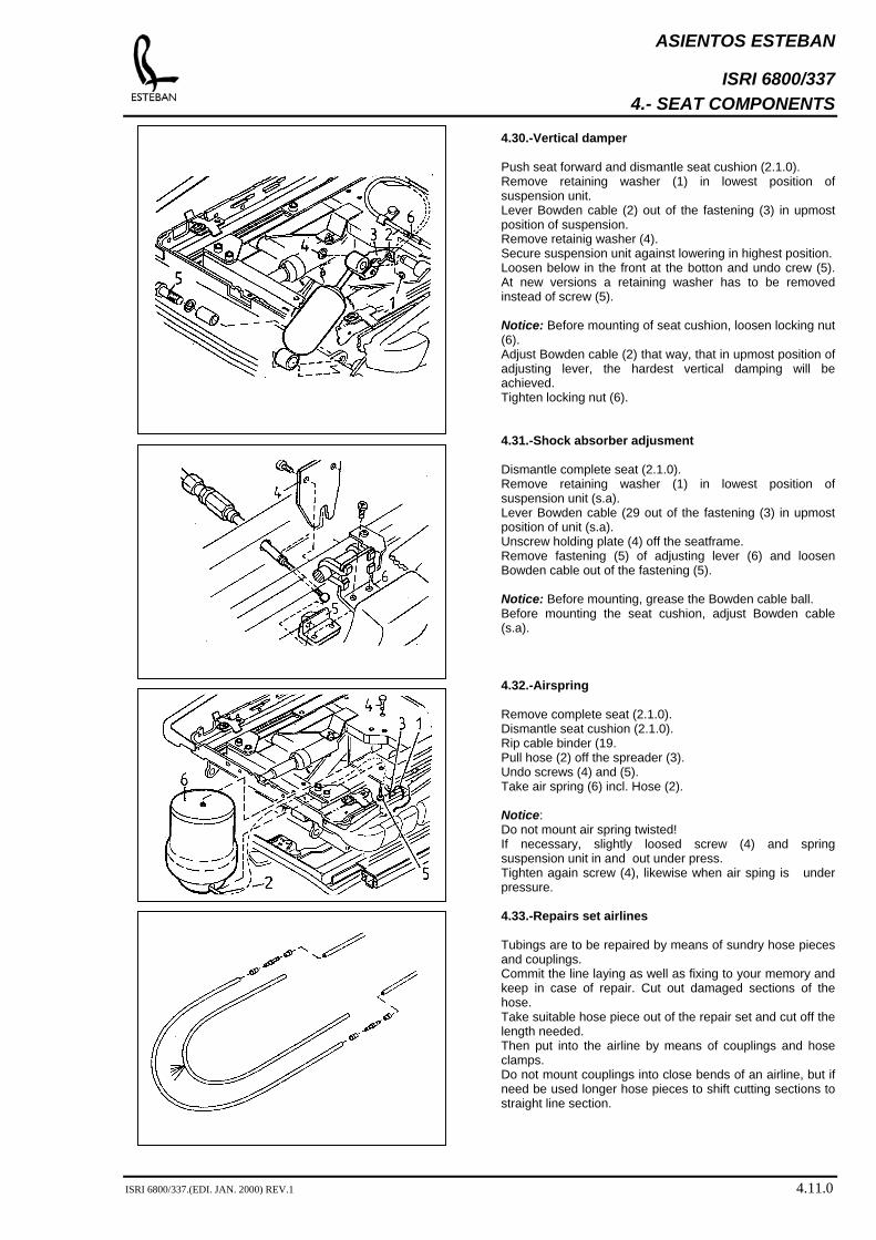
4.30.-Vertical damper Push seat forward and dismantle seat cushion (2.1.0). Remove retaining washer (1) in lowest position of suspension unit. Lever Bowden cable (2) out of the fastening (3) in upmost position of suspension. Remove retainig washer (4). Secure suspension unit against lowering in highest position. Loosen below in the front at the botton and undo crew (5). At new versions a retaining washer has to be removed instead of screw (5). Notice: Before mounting of seat cushion, loosen locking nut (6). Adjust Bowden cable (2) that way, that in upmost position of adjusting lever, the hardest vertical damping will be achieved. Tighten locking nut (6). 4.31.-Shock absorber adjusment Dismantle complete seat (2.1.0). Remove retaining washer (1) in lowest position of suspension unit (s.a). Lever Bowden cable (29 out of the fastening (3) in upmost position of unit (s.a). Unscrew holding plate (4) off the seatframe. Remove fastening (5) of adjusting lever (6) and loosen Bowden cable out of the fastening (5). Notice: Before mounting, grease the Bowden cable ball. Before mounting the seat cushion, adjust Bowden cable (s.a). 4.32.-Airspring Remove complete seat (2.1.0). Dismantle seat cushion (2.1.0). Rip cable binder (19. Pull hose (2) off the spreader (3). Undo screws (4) and (5). Take air spring (6) incl. Hose (2). Notice: Do not mount air spring twisted! If necessary, slightly loosed screw (4) and spring suspension unit in and out under press. Tighten again screw (4), likewise when air sping is under pressure. 4.33.-Repairs set airlines Tubings are to be repaired by means of sundry hose pieces and couplings. Commit the line laying as well as fixing to your memory and keep in case of repair. Cut out damaged sections of the hose. Take suitable hose piece out of the repair set and cut off the length needed. Then put into the airline by means of couplings and hose clamps. Do not mount couplings into close bends of an airline, but if need be used longer hose pieces to shift cutting sections to straight line section.
ISRI 6800/337.(EDI. JAN. 2000) REV.1 4.11.0

ASIENTOS ESTEBAN
ISRI 6800/337 4.- SEAT COMPONENTS
4.34.-Remaining pressure valve Version A: Seats with swivel base + subbase Version B: Seats without swivel base, with subbase. Version C: Seats without swivel base, without subbase. Remove seat from vehicle and turn around. Loosen out of fixing clamps (1), at version C cut cable binder (1) to pieces. Push clamping sleeves (2) off the spigots of remainig pressure valve (3) and pull off hoses. Mount new valve with blue connecting nipple towards vehicle connecting side. For hose securing use only new clamping sleeves (2). 4.35.-Secondary air volume Separate compressed air and power supply (optinal heating). Remove rear plastic cover (2.3.0). Cut cable binder to pieces, loosen sleeve nut (2) as well as hose clamp (3) and pull hoses off the secondary air volume (4). Renew felt plate. Fix new secondary air volume to the seatframe by means of cable binders (1), without including the tension wire (5).
ISRI 6800/337.(EDI. JAN. 2000) REV.1 4.12.0
ASIENTOS ESTEBAN
ISRI 6800/337 4.- SEAT COMPONENTS
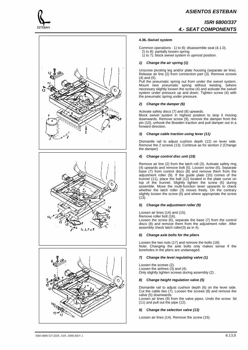
4.36.-Swivel system Common operations : 1) to 8): disassemble seat (4.1.0).
2) to 8): partially loosen spring. 1) to 7): block swivel system in upmost position.
1) Change the air spring (1) Unscrew pivoting leg and/or plate housing (separate air line). Release air line (2) from connection part (3). Remove screws (4) and (5). Pull the pneumatic spring out from under the swivel system. Mount new pneumatic spring without twisting. (where necessary slightly loosen the screw (4) and activate the swivel system under pressure up and down. Tighten screw (4) with the pneumatic spring under pressure. 2) Change the damper (6) Activate safety discs (7) and (8) upwards. Block swivel system in highest position to stop it moving downwards. Remove screw (9), remove the damper from the pin (10), unhook the Bowden traction and pull damper out in a forward direction. 3) Change cable traction using lever (11) Dismantle rail to adjust cushion depth (12) on lever side. Remove the 2 screws (13). Continue as for section 2 (Change the damper) 4) Change control disc unit (19)
Remove air line (2) from the latch roll (3). Activate safety ring (4) upwards and remove bolt (5). Loosen screw (6), Separate base (7) from control discs (8) and remove them from the adjustment roller (9). If the guide plate (10) comes of the trunnel (11), place the ball (12) located in the plate curve on top of the trunnel. Slightly tighten the screw (6) during assemble. Move the multi-function lever upwards to check whether the latch roller (3) moves freely. On the contrary slightly loosen the screw (6) and where appropriate the screw (13). 5) Change the adjustment roller (9) Loosen air lines (14) and (15). Remove roller bolt (16). Loosen the screw (6), separate the base (7) from the control discs (8) and remove them from the adjustment roller. After assembly check latch roller(3) as in 4). 6) Change axle bolts for the pliers
Loosen the two nuts (17) and remove the bolts (18). Note: Changing the axle bolts only makes sense if the boreholes in the pliers are undamaged. 7) Change the level regulating valve (1) Loosen the screws (2). Loosen the airlines (3) and (4). Only slightly tighten screws during assembly (2) . 8) Change height regulation valve (5) Dismantle rail to adjust cushion depth (6) on the lever side. Cut the cable ties (7). Loosen the screws (8) and remove the valve (5) downwards. Loosen air lines (9) from the valve pipes. Undo the screw lid (11) and pull out the pipe (12). 9) Change the selection valve (13) Loosen air lines (14). Remove the screw (15).
ISRI 6800/337.(EDI. JAN. 2000) REV.1 4.13.0
ASIENTOS ESTEBAN
ISRI 6800/337 4.- SEAT COMPONENTS
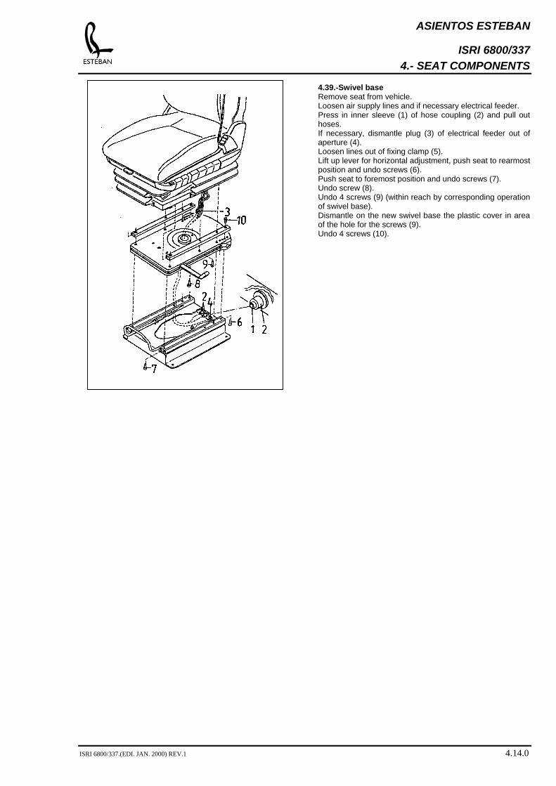
4.39.-Swivel base Remove seat from vehicle. Loosen air supply lines and if necessary electrical feeder. Press in inner sleeve (1) of hose coupling (2) and pull out hoses. If necessary, dismantle plug (3) of electrical feeder out of aperture (4). Loosen lines out of fixing clamp (5). Lift up lever for horizontal adjustment, push seat to rearmost position and undo screws (6). Push seat to foremost position and undo screws (7). Undo screw (8). Undo 4 screws (9) (within reach by corresponding operation of swivel base). Dismantle on the new swivel base the plastic cover in area of the hole for the screws (9). Undo 4 screws (10).
ISRI 6800/337.(EDI. JAN. 2000) REV.1 4.14.0
ASIENTOS ESTEBAN
ISRI 6800/337 5.- TROUBLESHOOTING; PNEUMATICS
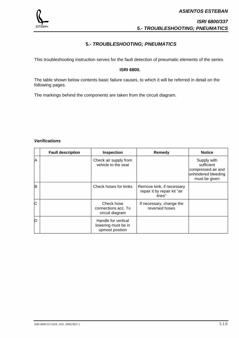
5.- TROUBLESHOOTING; PNEUMATICS This troubleshooting instruction serves for the fault detection of pneumatic elements of the series
ISRI 6800.
The table shown below contents basic failure causes, to which it will be referred in detail on the following pages. The markings behind the components are taken from the circuit diagram.
Verifications
Fault description Inspection Remedy Notice
A Check air supply from vehicle to the seat
Supply with sufficient
compressed air and unhindered bleeding
must be given
B Check hoses for kinks Remove kink, if necessary repair it by repair kit "air
lines"
C Check hose connections acc. To
circuit diagram
If necessary, change the reversed hoses
D Handle for vertical lowering must be in
upmost position
ISRI 6800/337.(EDI. JAN. 2000) REV.1 5.1.0
ASIENTOS ESTEBAN
ISRI 6800/337 5.- TROUBLESHOOTING; PNEUMATICS
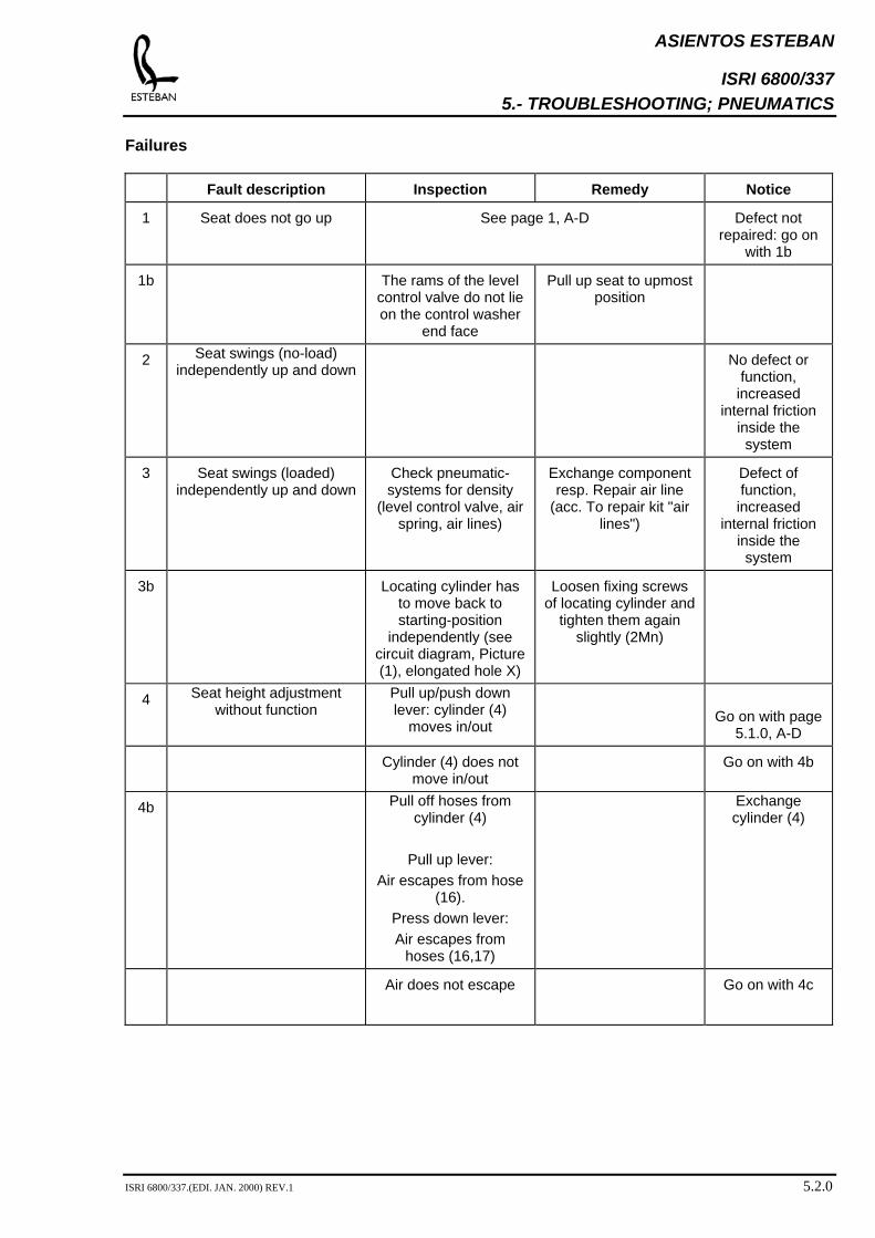
Failures
Fault description Inspection Remedy Notice
1
Seat does not go up See page 1, A-D Defect not repaired: go on
with 1b
1b
The rams of the level control valve do not lie on the control washer
end face
Pull up seat to upmost position
2 Seat swings (no-load) independently up and down
No defect or function, increased
internal friction inside the system
3 Seat swings (loaded) independently up and down
Check pneumatic-systems for density
(level control valve, air spring, air lines)
Exchange component resp. Repair air line
(acc. To repair kit "air lines")
Defect of function, increased
internal friction inside the system
3b
Locating cylinder has to move back to starting-position
independently (see circuit diagram, Picture (1), elongated hole X)
Loosen fixing screws of locating cylinder and
tighten them again slightly (2Mn)
4 Seat height adjustment without function
Pull up/push down lever: cylinder (4)
moves in/out
Go on with page
5.1.0, A-D
Cylinder (4) does not move in/out
Go on with 4b
4b Pull off hoses from cylinder (4)
Pull up lever:
Air escapes from hose (16).
Press down lever: Air escapes from
hoses (16,17)
Exchange cylinder (4)
Air does not escape Go on with 4c
ISRI 6800/337.(EDI. JAN. 2000) REV.1 5.2.0

ASIENTOS ESTEBAN
ISRI 6800/337 5.- TROUBLESHOOTING; PNEUMATICS
Fault description Inspection Remedy Notice
4c Check ram operation of valve for height
adjustment (7):
Ram will be pressed in at operation
Go on 4d
Ram will not be pressed in
Exchange operating lever
4d Pull hoses 9 and 11 off valve (7):
Air escapes when operating the lever
Go on 4e
Air does not escape when operating the
lever
Echange valve (7).
4e Check or-element ↑: pull of hoses 5 and 6 and operate height
adjustment upwards resp. Downwards
Air escapes rom hose 5 resp. 6
Exchange or-element (2).
5 Seat goes to upmost position and suspension
doesn´t work
See page 5.1.0, C
6 Seat bleeds permanetly out of exhaust air line E and
remains in upmost position
See page 5.1.0, C
7 Seat is resilient, but cannot be lowered by vertical
lowering
Check hose 19 for kinks
Remove kink. Res. repair it by repairing kit "air lines". If necessary
exchange vertical lowering (8).
ISRI 6800/337.(EDI. JAN. 2000) REV.1 5.3.0
ASIENTOS ESTEBAN
ISRI 6800/337 6.- PNEUMATICS PLAN
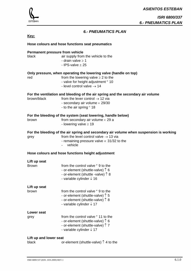
6.- PNEUMATICS PLAN
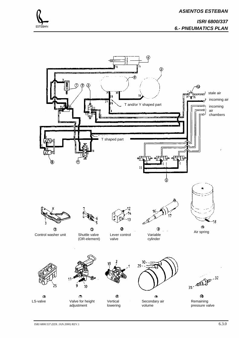
Key: Hose colours and hose functions seat pneumatics Permanent pressure from vehicle black air supply from the vehicle to the - drain valve ≥ 1 - IPS-valve ± 25 Only pressure, when operating the lowering valve (handle on top) red from the lowering valve ≥ 2 to the - valve for height adjustment ″ 10 - level control valve → 14 For the ventilation and bleeding of the air spring and the secondary air volume brown/black from the lever control → 12 via - secondary air volume × 29/30 - to the air spring ° 18 For the bleeding of the system (seat lowering, handle below) brown from secondary air volume × 29 a - lowering valve ≥ 19 For the bleeding of the air spring and secondary air volume when suspension is working grey from the level control valve → 13 via - remaining pressure valve ∝ 31/32 to the
- vehicle Hose colours and hose functions height adjustment Lift up seat Brown from the control valve ″ 9 to the - or-element (shuttle-valve) ↑ 6 - or-element (shuttle -valve) ↑ 8 - variable cylinder ↓ 16 Lift up seat brown from the control valve ″ 9 to the - or-element (shuttle-valve) ↑ 5 - or-element (shuttle-valve) ↑ 8 - variable cylinder ↓ 17 Lower seat grey from the control valve ″ 11 to the - or-element (shuttle-valve) ↑ 6 - or-element (shuttle-valve) ↑ 7 - variable cylinder ↓ 17 Lift up and lower seat black or-element (shuttle-valve) ↑ 4 to the
ISRI 6800/337.(EDI. JAN.2000) REV.1 6.1.0
ASIENTOS ESTEBAN
ISRI 6800/337 6.- PNEUMATICS PLAN
variable cylinder ← 3
ISRI 6800/337.(EDI. JAN.2000) REV.1 6.2.0
ASIENTOS ESTEBAN
ISRI 6800/337 6.- PNEUMATICS PLAN
Remaining pressure valve
Secondary air volume
Vertical lowering
Valve for height adjustment
LS-valve
Air spring Variable cylinder
Lever control valve
Shuttle valve (OR-element)
Control washer unit
T shaped part
incoming air chambers
incoming air
stale air
T and/or Y shaped part
ISRI 6800/337.(EDI. JAN.2000) REV.1 6.3.0
ASIENTOS ESTEBAN
ISRI 6800/337 7.- REPAIR TIMES
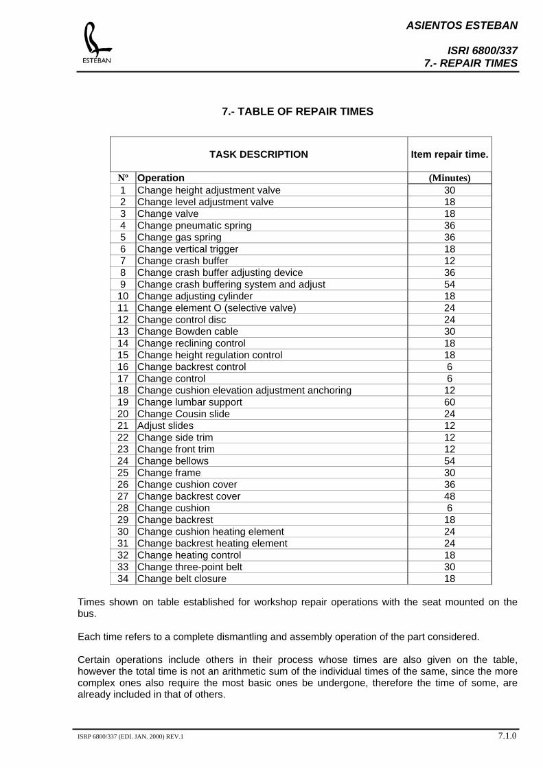
7.- TABLE OF REPAIR TIMES
TASK DESCRIPTION
Item repair time.
Nº Operation (Minutes) 1 Change height adjustment valve 30 2 Change level adjustment valve 18 3 Change valve 18 4 Change pneumatic spring 36 5 Change gas spring 36 6 Change vertical trigger 18 7 Change crash buffer 12 8 Change crash buffer adjusting device 36 9 Change crash buffering system and adjust 54
10 Change adjusting cylinder 18 11 Change element O (selective valve) 24 12 Change control disc 24 13 Change Bowden cable 30 14 Change reclining control 18 15 Change height regulation control 18 16 Change backrest control 6 17 Change control 6 18 Change cushion elevation adjustment anchoring 12 19 Change lumbar support 60 20 Change Cousin slide 24 21 Adjust slides 12 22 Change side trim 12 23 Change front trim 12 24 Change bellows 54 25 Change frame 30 26 Change cushion cover 36 27 Change backrest cover 48 28 Change cushion 6 29 Change backrest 18 30 Change cushion heating element 24 31 Change backrest heating element 24 32 Change heating control 18 33 Change three-point belt 30 34 Change belt closure 18
Times shown on table established for workshop repair operations with the seat mounted on the bus. Each time refers to a complete dismantling and assembly operation of the part considered. Certain operations include others in their process whose times are also given on the table, however the total time is not an arithmetic sum of the individual times of the same, since the more complex ones also require the most basic ones be undergone, therefore the time of some, are already included in that of others.
ISRP 6800/337 (EDI. JAN. 2000) REV.1 7.1.0