WORKSHOP MANUAL - London Taxi Parts USA
54
BRAKES Section 7 ª LONDON TAXIS INTERNATIONAL HOLYHEAD ROAD COVENTRY CV5 8JJ Sec 7 5/99 WORKSHOP MANUAL Section 7 Brakes
Transcript of WORKSHOP MANUAL - London Taxi Parts USA

BRAKES Section 7
LONDON TAXIS INTERNATIONAL HOLYHEAD ROAD COVENTRYCV5 8JJ
Sec 7 5/99
WORKSHOPMANUAL
Section 7
Brakes

BRAKES Section 7
TX1 Workshop Manual Page 2 Sec 7 5/99
At the time of going to print, the illustrations andtext appearing in this workshop manual arerepresentative of manufacture. Whilst retaining thebasic features shown herein, the manufacturerreserves the right to make, at any time, andwithout necessarily updating this manual, anyalterations considered convenient for improvementor for any other reason.
Whilst every effort is made to ensure the accuracyof the particulars contained herein, LTI will notunder any circumstances be held liable for anyinaccuracies or the consequences thereof.

BRAKES Section 7
TX1 Workshop Manual Page 3 Sec 7 5/99
Contents Page
GENERAL DESCRIPTION 4KEY DATA 6GENERAL PRECAUTIONS 8FAULT DIAGNOSIS 10FRONT BRAKE PADS 16FRONT BRAKE DISC 19FRONT BRAKE CALIPERS 22FRONT BRAKE HOSES 26REAR BRAKE DRUMS/SHOES/BRAKE ADJUSTERS 28REAR WHEEL CYLINDER 35REAR BRAKE BACKPLATE 38REAR BRAKE HOSE 39MASTER CYLINDER 40BRAKE SERVO/VACUUMSEAL/AIR FILTER 45BRAKE BLEEDING 47HANDBRAKE REAR CABLE 49HANDBRAKE FRONT CABLE 53

BRAKES Section 7
TX1 Workshop Manual Page 4 Sec 7 5/99
GENERAL DESCRIPTION
Fig. 1 Braking system – hydraulic layout
The dual line hydraulic braking system isoperated by a vacuum servo assisted tandemmaster cylinder located on the enginebulkhead. The 278 mm (10.9 in.) ventilateddisc front brakes with 4 - pot brake calipersare complemented by 254 X 70 mm (10 X 2.75in.) self adjusting drum rear brakes.
Rear brake adjustment is achieved by meansof a linkage within each rear brake assemblywhich operates a ratchet to progressively takeup excessive brake shoe travel as the brakelinings wear in service.
BRAKES Section 7
TX1 Workshop Manual Page 5 Sec 7 5/99
GENERAL DESCRIPTION
The primary brake hydraulic circuit isconnected to one set of opposing cylinders ineach front brake caliper and to both rearbrakes, the rear brake pipe incorporating aPRV (pressure reducing valve) to reduce thepossibility of rear wheel lock up. Thesecondary brake hydraulic circuit is connectedto a second set of cylinders in each frontcaliper. This 'H + I' hydraulic layout providesbraking effort to both front brakes from boththe primary and secondary circuits in thesystem.
One of the pads fitted to the right hand caliperincorporates wiring which illuminates awarning lamp on the facia when the brakepads require replacement. The handbrake iscable operated.
The engine mounted vacuum pump isconnected through an in - line non returnvalve to the brake servo unit, and incorporatesa sensor to operate a warning light in theevent of failure. The servo unit will provideservo assistance for a number of brakeapplications should the vacuum pump fail,after which braking effort is still availablewithout assistance.
BRAKES Section 7
TX1 Workshop Manual Page 6 Sec 7 5/99
KEY DATA
BRAKE FLUID FMVSS 116 DOT 4FRONT BRAKE DISCS:
RUN OUT 0,1 mm (0.004 in.)MAXIMUM WEAR PER SIDE 1.0 mrn (0.040 in.)MINIMUM THICKNESS 22,0 mm (0.875 in.)
REAR DRUM BRAKES:RUN OUT 0.1 mm (0.004 in.)MAXIMUM WEAR 2.0 mm (0.080 in.)MAX DRUM OVALITY 0.05 mm (0.002 in.)
TORQUE SETTINGS: Nm lbf. ftCaliper to steering knuckles 92-125 70-92Disc to hub 45-55 33-41Axle bearing retainer to rear axle 68-81 52-60Master cylinder to servo 34-51 26-37Reservoir to master cylinder 5.6-6.8 4-5Caliper Bleed screws 7.9-10.1 6-7.5Rear cylinder bleed screws 5.1-6.2 4-4.5Hoses 13.5-16.0 10-12Hydraulic pipe nuts (female) 17.0-20.0 12.5-14.5Hydraulic pipe nuts (male) except 14.0-17.0 10-12
rear pipe to PRVRear hydraulic pipe to PRV 12.0-14.0 9.0-10.5
Service Requirements
1000 miles/1500 Km Check/top-up brake & clutch fluid levels.Check/adjust handbrake cable. Lubricate exposedparts of linkage.Inspect brake hoses, pipes & connectors forchafes/leakage.Check operation of brake fluid level warning light.
9000 miles/15000 Km Check/top-up brake & clutch fluid levels.Check/adjust handbrake cable. Lubricate exposedparts of linkage.Inspect brake hoses, pipes & connectors forchafes/leakage.Check front brake pads for wear.Clean out rear brake drums check brake linings forwear & replace as necessary. Examine brakemechanism condition & cylinders for leakage.Check operation of brake fluid level warning light.
BRAKES Section 7
TX1 Workshop Manual Page 7 Sec 7 5/99
Service Requirements (Cont’d)
18000 miles/30000 Km Check/top-up brake & clutch fluid levels.Check/adjust handbrake cable. Lubricate exposedparts of linkage.Inspect brake hoses, pipes & connectors forchafes/leakage.Remove front brake pads, examine condition &wear, replace as necessary. Check calipers forsigns of leakage.Clean out rear brake drums check brake linings forwear & replace as necessary. Examine brakemechanism condition & cylinders for leakage.Check operation of brake fluid level warning light.
54,000 miles (90,000 Km) Replace brake & clutch system fluid & bleed& each 54,000 miles (90,000 Km) systems.thereafter
72,000 miles (120,000 Km) or 3 years Examine the master cylinder, calipers and wheel(whichever occurs first) all fluid seals and flexible brake hoses.
Refill the braking system with new fluid of thespecific type and bled the braking system.Replace the brake servo air filter.
Special tools
'E' clip fitting tool Automotive Products STL 107
Caliper piston clamp SPX Churchill MS 331
Rear Brake Steady Post Retainer compressor Snap on S 6118 (adapter), TM9CSA (handle)

BRAKES Section 7
TX1 Workshop Manual Page 8 Sec 7 5/99
GENERAL PRECAUTIONS
NOTE: Vehicles fitted with the type of brakingsystem fitted to the TX1 have longer brake pedaltravel than vehicles with less sophisticatedbraking systems. Pedal travel will increase as thelinings wear and prior to each automatic shoeadjustment. Never try to reduce brake pedaltravel by adjusting the handbrake mechanism -with the hand brake 'off', there should be no loadon the handbrake operating mechanism.
1. Disc brake pads, drum brake linings,hoses and pipes should be examinedregularly at intervals no greater thanthat specified in the maintenanceschedule for the vehicle.
2. Over a period, brake fluid absorbsmoisture and becomes contaminatedwith minute particles from the seals inthe hydraulic system. The fluid shouldbe changed completely every 54,000miles (90,000Km) and each 54,000miles thereafter.
3. Vehicles operating under severeconditions, in areas where a largeproportion of driving takes place onsteep hills, brake fluid changes shouldbe made at more frequent intervals.
4. All fluid seals in the hydraulic systemand all hoses should be replaced every72,000 miles (120,000 Km) or 3 years(whichever occurs first). At the sametime, the working surfaces of thepistons and bores in the mastercylinder, calipers and wheel cylindersshould be examined and new partsfitted where necessary.
5. Always use the specified FMVSS 116DOT 4 brake fluid. Never use petrol orparaffin to clean braking systemcomponents - if solvent is required usemethylated spirit, or purpose madebrake cleaner.
6. Never leave unused brake fluid inunsealed containers where it will absorbmoisture and can be dangerous if usedin a braking system in this condition.
7. Fluid drained from the system or used inbleeding should be discarded.

BRAKES Section 7
TX1 Workshop Manual Page 9 Sec 7 5/99
GENERAL PRECAUTIONS
8. The necessity for absolute cleanlinesswhen any work is undertaken on thehydraulic system cannot be overemphasized.
9. Brake pads and shoes should always bereplaced with those specified by themanufacturer. Always replace pads andshoes in axle sets.
10. Never blow out brake drums. Removebrake dust with a vacuum cleaner orwipe clean with a damp rag.
11. Before carrying out any work on thebraking system always relieve thevacuum in the servo unit by operatingthe brake pedal several times with theengine stopped.
12. Never work under a vehicle whensupported only by a jack; always usesafety stands however small the serviceoperation involved.
13. While it may not be mentioned in theindividual repair operations, it isessential that work is inspected andtested following a repair. Where safetyrelated items are involved, the vehicleshould be road tested before beinghanded over to the customer.

BRAKES Section 7
TX1 Workshop Manual Page 10 Sec 7 5/99
FAULT DIAGNOSIS
SYMPTOM POSSIBLE CAUSE ACTION NECESSARY
Fall of fluid level inmaster cylinderreservoir.
1. Normal friction pad or brakewear.
Top up the fluid reservoir to the correctlevel, then check daily for the next fewdays. If the level again fails significantlycarry out the procedure for 'hydraulic fluidleak'.
2. Hydraulic fluid leak. Visually check the hydraulic connections forleaks, including the master cylinder, PRV,calipers and wheel cylinders, peeling backrubber boots where necessary. Tighten anyloose connections found, but if the leakpersists the suspect component must berepaired or replaced.
Excessive travel offootbrake pedal orthe handbrake lever.
1. Failure of one hydrauliccircuit in the braking system.
Carry out procedure for 'hydraulic fluid leak'to isolate fault. If no leak is apparent,dismantle the master cylinder, and if thebore and pistons are in perfect condition,service the assembly with the appropriaterepair kit otherwise replace the completemaster cylinder.
2. Excessive run-out of brakedisc caused by worn or out ofadjustment wheel bearings.
Renew or adjust the wheel bearings asspecified in the workshop manual.Disc run out can sometimes be improved byfitting the brake disc to the hub in analternative position.Disc run out should not exceed a dimensionof 0,1 mm (0.004 in.).
3. Handbrake cable out ofadjustment or inoperative rearbrake adjuster mechanism
Adjust the handbrake rear cable as detailedin the workshop manual. If the faultpersists, remove the rear brake drums andcheck that the automatic rear adjusters arefunctioning correctly. Rectify as necessary.
Spongy brake pedal. 1. Fluid level drop in mastercylinder reservoir allowing airinto the hydraulic system.
Thoroughly bleed the system, refillreservoir to the correct level and carry outthe procedure for 'hydraulic fluid leak’.
2. Faulty brake hose. Check all hoses for leakage or ballooningunder pressure. Replace any defectivehoses as necessary.

BRAKES Section 7
TX1 Workshop Manual Page 11 Sec 7 5/99
FAULT DIAGNOSIS
SYMPTOM POSSIBLE CAUSE ACTION NECESSARY
Brake drag - allbrakes
1. Mechanical binding orobstruction of foot pedal.
Check that the footbrake pedal returns tothe 'off' position and is not obstructed forany reason.
2. Hydraulic pressure build upin the master cylinder.
Slacken the tube nuts at the mastercylinder, if this releases the brakes theremay be contaminated brake fluid in thesystem causing rubber components to swellblocking the by-pass ports and trappinghydraulic pressure. Refer to the 'actionnecessary' below.
3. Rubber cups or seals swollendue to brake fluidcontamination by petrol,paraffin or mineral oil., etc.
Contamination may sometimes beconfirmed by the characteristic smell in thefluid reservoir. Although the degree ofswelling is relative to the severity ofcontamination, when withdrawn from thecylinder usually the swollen rubber sealsmay be easily recognized as oversize. Allrubber parts such as cups, seals, andflexible hoses must be changed. Thoroughlyflush the system with new brake fluidbefore fitting the new parts.
Brake Drag - onebrake.
1. Disc pads seized or stickingin a caliper recess.
Remove the split pins, retaining pins andsprings, withdraw the pads and clean thecaliper recess with a damp rag. Do not blowout with an air line as it could be harmful toinhale the dust. Clean all dirt from the padsand inspect the condition of the anti-sealmaterial on the back of the pads. Ensurethe specified pads have been fitted. Refitthe pads, retaining pins, springs and splitpins and check that the disc spins freely.
2. Seized piston in disc brakecaliper or wheel cylinder.
Remove the disc pads or brake drum asapplicable, then carefully depress the footpedal to check the movement of the pistonsin the suspect assembly. If a piston isseized the complete caliper or wheelcylinder must be replaced.
3. Obstruction in a flexiblehose.
Isolate the fault, disconnect the brake hoseto confirm the complaint then renew thedefective brake hose.
BRAKES Section 7
TX1 Workshop Manual Page 12 Sec 7 5/99
FAULT DIAGNOSIS
SYMPTOM POSSIBLE CAUSE ACTION NECESSARY
Brake Drag - onebrake.
4. Incorrect adjustment orseizure of the handbrakeassembly.
Examine the handbrake cable, clevis pinsand yokes etc., also the handbrakemechanism at the brake backplate, ifnecessary removing the brake drum toconfirm correct operation of theseg-adjusting mechanism. Adjust the rearhandbrake as necessary.
5. Weak or broken brake shoepull off springs.
Remove the brake drum and carefullyexamine the assembly. If a weak spring issuspected replace all the pull off springs.
Unbalanced brakingwith pull or judder
1 . Loose caliper mountingbolts, loose backplate, steeringand suspension components,tyre pressures or condition.
Check the security of the brake assembliesand for wear on the steering andsuspension parts. Ensure the tyres are atthe recommended pressures and are ingood condition and of the correct type.
2. Disc brake pads or shoelinings contaminated with oil,grease, or hydraulic fluid.
Examine the brake pads and shoes toconfirm complaint then establish the causeof contamination and rectify by replacingany defective parts. A minor degree offriction material contamination may beremoved with fine emery cloth, but at thesame time moisten with a damp rag as itcould be harmful to inhale the dust.Otherwise if contamination is severe thedisc pads and brake shoes must bereplaced in sets irrespective of their state ofwear.
3. Different grades of pad liningmaterial used in an axle set.
Remove the disc pads or brake shoes andcheck that the friction material is not ofdifferent grades. Otherwise replace thepads or shoes in complete axle sets.
4. Seized pistons in disc brakecaliper or wheel cylinder.
Remove the disc pads or brake drum asapplicable, then carefully depress thefootbrake pedal to check movement of thepistons in the suspect assembly. If a pistonis seized the complete caliper or wheelcylinder must be replaced.

BRAKES Section 7
TX1 Workshop Manual Page 13 Sec 7 5/99
FAULT DIAGNOSIS
SYMPTOM POSSIBLE CAUSE ACTION REQUIRED
Unbalanced braking with pull orjudder (continued).
5. If associated with judder,surface condition and run out ofdiscs, or excessive run out ofbrake drums.
Ensure that the wheel bearingsare not worn or out ofadjustment, replace or adjust asnecessary. Minor disc frictionsurface imperfections may beremoved with a fine emerycloth, if in doubt replace thedisc. Check the disc run outwhich must not exceed adimension of 0,1 mm (0.004in.). Check and compare thethickness of the disc at variouspoints around the frictionsurface. If a thick/thin conditionis confirmed replace the disc.Brake discs should not bereground in service. Disc wearmust not exceed 0, 1 mm(0.004 in.). each side and discthickness must not be less than22,0mm (0.875 in.). Rear brakedrum judder may be detectedby gently applying thehandbrake at low speed. Drumrun out may be checked with adial gauge by fitting the brakedrum to the hub the wrong wayround. Run out must not exceeda dimension of 0,1 mm (0.004in.). Drum ovality must notexceed a dimension of0.025mm (0.001 in.).
Brakes inefficient givingincreased brake pedal effort.
1. Servo unit inoperative. With the engine off depress thebrake pedal several times torelieve all vacuum from theservo unit, during this operationthe air control valve should hissevery time the pedal is pressed.With all vacuum released, applylight pressure to the brakepedal and start the engine, ifthe servo is working the pedalwill appreciably sink down asthe servo operates. With thebrakes held on there should beno hiss from the air inlet. Thesetests are not exhaustive,therefore, if the servo unit givescause for doubt as to itsperformance it is advisable toreplace the unit.

BRAKES Section 7
TX1 Workshop Manual Page 14 Sec 7 5/99
FAULT DIAGNOSIS
SYMPTOM POSSIBLE CAUSE ACTION NECESSARY
Brakes inefficientgiving increasedbrake pedal effort(continued).
1. Servo unit inoperative.(continued)
A continuous hiss from the servo servo unitvacuum seal may indicate a worn or faulty
2. Glazed or worn out pads orlinings.
Glazed surfaces on pads or shoes can beremoved by rubbing down with roughsandpaper, but at the same time moistenwith a damp rag as it could be harmful toinhale the dust. Otherwise d worn down tothe stated limits replace the pads or shoes.
3. Damaged or rusty frictionsurface of brake discs.
Examine the brake discs for cracks, scoring,or a rust deposit which after being subjectto heat by the pads gives the frictionsurfaces a black appearance. Minor surfaceimperfections may be removed with fineemery cloth but such faults may render thedisc inefficient, therefore, if any doubtexists renew the disc.
4. Disc pads or shoescontaminated with oil, greaseor hydraulic fluid.
Examine the pads or shoes to confirmcomplaint then establish the cause ofcontamination and rectify by replacing anydefective parts. A minor degree of frictioncontamination may be removed with a fineemery cloth, but at the same time moistenwith a damp rag as ft could be harmful toinhale the dust. Otherwise if contaminationis severe the disc brake pads or brakeshoes must be replaced in axle setsirrespective of their state of wear.
5. Seized piston(s) in discbrake caliper or wheel cylinder
Remove the disc pads or brake drum asapplicable, then carefully depress thefootbrake pedal to check movement of thepistons in the suspect assembly. If a pistonis seized the complete caliper or wheelcylinder assembly must be replaced.
Disc brake squeal. 1. High frequency padvibration.
Withdraw the disc brake pads. Clean all dirtfrom the pads and inspect the condition ofthe anti-squeal coating on the back of thepads. Ensure the specified pads have beenfitted. Refit the pads and secure with theretaining pins, springs and split pins.

BRAKES Section 7
TX1 Workshop Manual Page 15 Sec 7 5/99
FAULT DIAGNOSIS
SYMPTOM POSSIBLE CAUSE ACTION REQUIRED
Disc brake squeal(continued).
2. Loose caliper mounting bolts. Confirm this possible cause andrectify by tightening themounting bolts to 95 - 125 Nm(70-92 lbf. ft.)
Brake drum squeal. 1. Lack of lubrication and/orexcessive dust in brakeassembly.
Remove the brake drum, thenthe shoes and other parts andclean the assembly. Do notblow out with an air line as itcould be harmful to inhale thedust, but remove the dust witha vacuum cleaner or wipe cleanwith a damp rag. Lightly smearwith Lockheed Expanderlubricant the tips of the brakeshoes, the cylinder andabutments slots, also the areaof the backplate where thebrake shoe platforms makecontact. Ensure that the frictionsurface of the drum is clean, donot allow the grease to contactthe shoe linings, rubber parts orthe friction surface of the drum.

BRAKES Section 7
TX1 Workshop Manual Page 16 Sec 7 5/99
FRONT BRAKE PADS
Wear IndicatorLead
Fig 2. Front disc brake components
BRAKES Section 7
TX1 Workshop Manual Page 17 Sec 7 5/99
FRONT BRAKE PADS
Remove/Replace/Examine
NOTE: BRAKE PADS MUST ALWAYS BEREPLACED IN AXLE SETS USING THE NONASBESTOS REPLACEMENT BRAKE PADSSPECIFIED BY THE MANUFACTURER. NEVERREPLACE BRAKE PADS INDIVIDUALLY OR ASA SINGLE WHEEL SET. SERIOUSCONSEQUENCES COULD RESULT FROM OUTOF BALANCE BRAKING DUE TO A MIX OFBRAKE FRICTION MATERIALS
1. Apply the handbrake and chock the rearwheels. Remove the front hub caps andpartly release the front wheel nuts.Raise the front of the vehicle andsupport it on stands placed under thechassis members. Remove the roadwheels.
2. Disconnect the plug of the lead to thebrake wear sensor fitted to the innerbrake pad of the right hand side brakeby pressing the square sides of itssocket to release the latches on the sideof the plug.
3. Working on one caliper at a time, cleanthe outside of the caliper assembly (usemethylated spirit and a wire brush dnecessary to move excessive road dirt).
4. Remove the two split pins which securethe pad retaining pins. Withdraw theretaining pins and springs. Lift the padsout of the caliper assembly.
5. Examine the brake pads. Regardless ofthe state of wear, the pads must bereplaced if there is any sign of crackingbetween the friction material and themetal backplate. If the friction materialhas worn down to 3mm (0.125 in.)thepads must be replaced.
6. Fit the brake pads into the caliperassembly – the pad with the sensorleads should be fitted to the inside ofthe right hand brake assembly and thesensor plug reconnected.

BRAKES Section 7
TX1 Workshop Manual Page 18 Sec 7 5/99
FRONT BRAKE PADS
Remove/Replace/Examine(Cont’d)
NOTE: When new pads are replacing wellworn pads it will be necessary to carefullypress the brake pistons into the caliperhousings. During this operation brake fluid willbe displaced. To prevent the reservoiroverflowing, fit a bleed tube to the relevantbrake bleed screw and release the brake fluidinto a container. Retighten the bleed screwwhen the pistons are fully retracted. Discardthe removed brake fluid.
Check the bearing edges of new pads forblemishes (high spots on the steel pressureplates may be carefully removed with asmooth file).
7. Refit the pad retaining springs andsprings. Secure the retaining pins withsplit pins using new parts as required.
8. Repeat operations 3 - 7 for the otherside of the vehicle.
9. Refit the front road wheels tighteningthe securing nuts as much as possible.
10. Lower the vehicle and torque the wheelnuts to specification (torque 200 Nm,150 lbf. ft). Replace the hub cap.
11. Operate the foot brake to 'bed' thebrake pads. Check the brake fluid levelin the fluid reservoir and correct asnecessary. Always use new brake fluidto specification FMVSS 116 DOT 4.
NOTE: Remember new brake pads may takeseveral hundred miles to fully 'bed in'. The'bedding in' process will be extended if thebrake discs are not in good condition.

BRAKES Section 7
TX1 Workshop Manual Page 19 Sec 7 5/99
FRONT BRAKE DISC
Remove/Replace
1. Remove the hub cap and partly releasethe wheel nuts. Chock the rear wheels.Raise the front of the vehicle andsupport it on stands placed under thechassis members. Remove the roadwheel.
2. Make a suitable wire support for thebrake caliper assembly and hang thesupport on the chassis side memberbehind the front suspension. Removethe two bolts securing the brake hosesecuring bracket to the steeringknuckle. (When working on the righthand side, remove the brake pad wearsensor lead plug by pressing the squaresides of its socket to release the latcheson the side of the plug. The earth leadfor the sensor is under the head of thehose securing bracket inner bolt).Remove the two bolts securing thecaliper assembly and carefully hang theassembly on the wire support so thatthe brake hoses are not stressed andthe caliper is not damaged.
3. Remove the hub dust cap with asuitable lever. Remove the split pin, nutretainer, hub bearing nut and tabwasher.
NOTE: The hub bearing nut should normallybe at most just finger tight.
4. Carefully pull the hub and disc assemblyfrom the steering knuckle spindle torelease the outer hub cone, and removethe hub and disc assembly.
5. Support the hub assembly in a roadwheel to allow the brake disc capscrews to be removed and discarded.Check the disc mounting surface isclean and free from burrs andimperfections before fitting a new discwith new cap screws (torque 45-55 Nm,33-41 lbf. ft.).
BRAKES Section 7
TX1 Workshop Manual Page 20 Sec 7 5/99
FRONT BRAKE DISC
Remove/Replace (Cont’d)
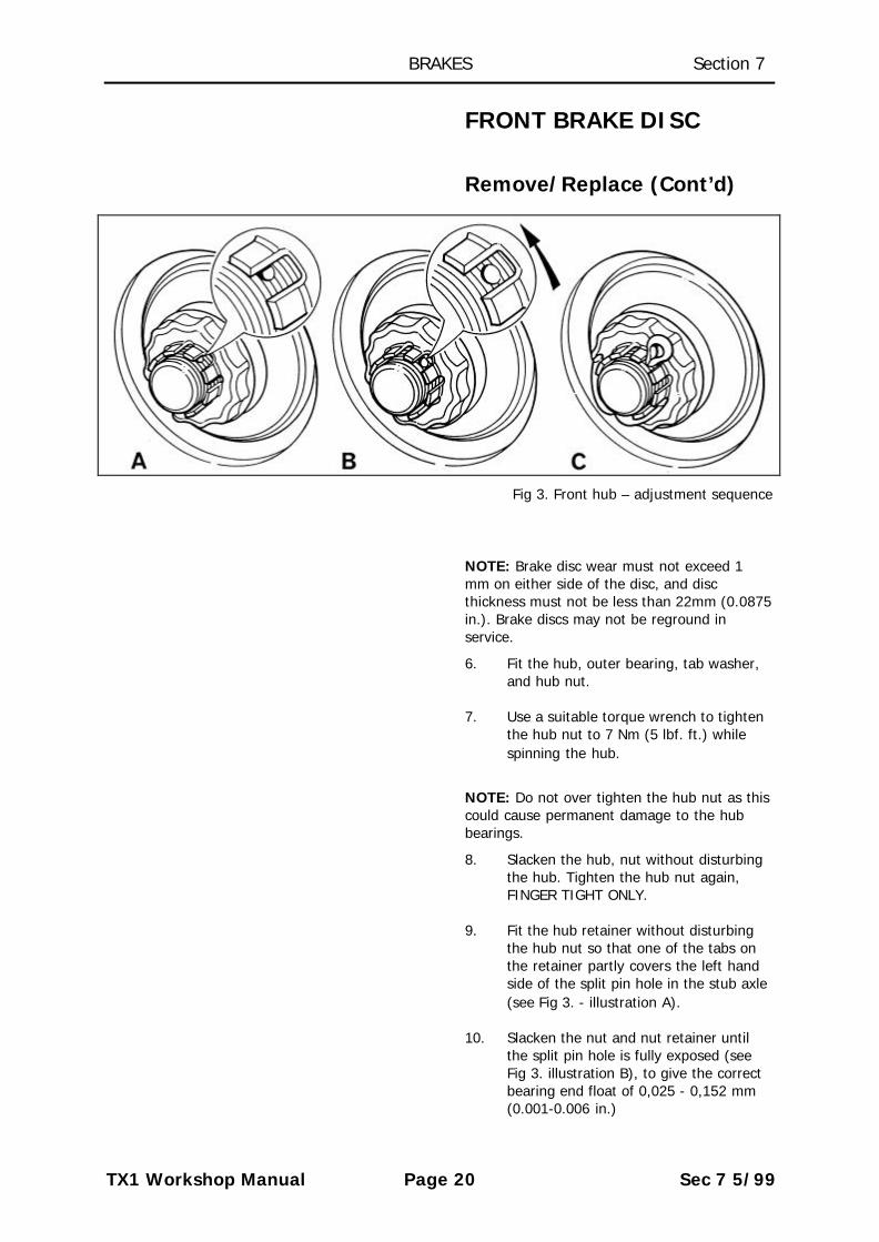
Fig 3. Front hub – adjustment sequence
NOTE: Brake disc wear must not exceed 1mm on either side of the disc, and discthickness must not be less than 22mm (0.0875in.). Brake discs may not be reground inservice.
6. Fit the hub, outer bearing, tab washer,and hub nut.
7. Use a suitable torque wrench to tightenthe hub nut to 7 Nm (5 lbf. ft.) whilespinning the hub.
NOTE: Do not over tighten the hub nut as thiscould cause permanent damage to the hubbearings.
8. Slacken the hub, nut without disturbingthe hub. Tighten the hub nut again,FINGER TIGHT ONLY.
9. Fit the hub retainer without disturbingthe hub nut so that one of the tabs onthe retainer partly covers the left handside of the split pin hole in the stub axle(see Fig 3. - illustration A).
10. Slacken the nut and nut retainer untilthe split pin hole is fully exposed (seeFig 3. illustration B), to give the correctbearing end float of 0,025 - 0,152 mm(0.001-0.006 in.)

BRAKES Section 7
TX1 Workshop Manual Page 21 Sec 7 5/99
FRONT BRAKE DISC
Remove/Replace (Cont’d)
NOTE: Never set the front wheel bearings tootight; the bearing nut should be loose afterfollowing this setting procedure. Correctly setthe bearings should have just perceptible endfloat - if in doubt check the end float with adial gauge.
11. Fit a new split pin, and replace the hubdust cap.
NOTE: If a new brake disc has been fitted,the brake disc run out must be checked with adial gauge. Brake disc run out must notexceed 0,1 mm.
12. Check the brake pad wear and replacethe pads as necessary. Refit the brakecalipers and torque the two calipersecuring bolts to specification 95 -125Nm, 70-92 lbf. ft. Remove the wirecaliper support.
13. Replace the brake hose securing bracketand earth lead (RHS only), ensuring thebrake hoses follow their natural curveclear of the suspension. Refit the brakepad wear sensor lead plug (RHS only).
14. Refit the road wheel tightening thesecuring nuts as much as possible.
15. Lower the vehicle and torque the wheelnuts to specification (torque 200 Nm,150 lbf. ft.). Replace the hub cap.
16. Start the engine and pump the brakepedal to position the brake pads to theircorrect position. Stop the engine.

BRAKES Section 7
TX1 Workshop Manual Page 22 Sec 7 5/99
FRONT BRAKE CALIPERS
Remove/Replace/Overhaul
NOTE: THE CALIPER UNIT IS SERVICED AS ACOMPLETE ASSEMBLY, LESS BRAKE PADS. DONOT ATTEMPT TO SEPARATE THE TWOHALVES OF THE CALIPER ASSEMBLY TOREPLACE THE PISTON SEALS.
1. Remove the brake pads as previouslydescribed. Place a receptacle under thecaliper to receive any displaced brakefluid. Remove the bolts securing thecaliper assembly to the steeringknuckle, disconnect and plug thehydraulic pipes to prevent dirt ingressand fluid loss, and remove the caliperassembly. If the caliper assembly is tobe overhauled, thoroughly clean theoutside of the caliper assembly and thepad recesses using methylated spirit orbrake fluid. If the caliper assembly is tobe replaced, proceed to operation 9.
2. Use the special tool MS 331 to hold twoadjacent pistons into the caliper body.Place a suitable block of wood into thecaliper recess to hold one of theremaining pistons.
NOTE: CARE SHOULD BE TAKEN WHENCARRYING OUT THE NEXT OPERATION TOENSURE THE FINGERS ARE NOT TRAPPED ASTHE PISTONS ARE EJECTED FROM THEPISTON BORES.
Place a rag into the brake caliper recess toprotect the unsupported piston. Apply gentleair pressure from an air line to the brake pipeorifice leading to the unsupported piston toeject the piston from its bore until it issufficiently exposed to allow it to be removedby hand.
NOTE: If any of the pistons is seized, thecomplete caliper assembly must be replaced.
BRAKES Section 7
TX1 Workshop Manual Page 23 Sec 7 5/99
FRONT BRAKE CALIPERS
Remove/Replace/Overhaul(Cont’d)
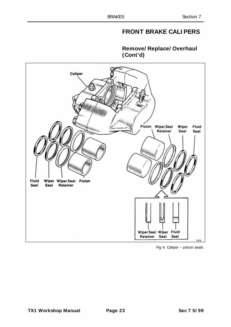
Fig 4. Caliper – piston seals

BRAKES Section 7
TX1 Workshop Manual Page 24 Sec 7 5/99
FRONT BRAKE CALIPERS
Remove/Replace/Overhaul(Cont’d)
3. The wiper seal can be removed byinserting a blunt screwdriver betweenthe retainer and the seal to prise theretainer carefully from the mouth of thepiston bore. Taking great care not todamage the seal grooves in the cylinderbore, extract the wiper seal and thefluid seal.
4. Thoroughly clean the bore, piston andthe seal grooves with new brake fluid ormethylated spirit. If the caliper or pistonis corroded, or their condition is notperfect, the parts must be replaced.
5. Coat the new fluid seal with LockheedDisc Brake Lubricant. Ease the seal intothe groove in the bore using only thefingers, ensuring that it is correctlyseated into the groove. The fluid sealgroove and the seal are not the same insection, thus when bedded the sealfeels proud to the touch at the edgefurthest from the mouth of the bore.
6. Slacken the relevant bleed screw on thecaliper one complete turn and afterlightly coating the piston with LockheedDisc Brake Lubricant insert it squarelyinto the bore using only the fingers. Donot tilt the piston during insertion andleave approximately 8 mm (5/16 in.)protruding from the mouth of the bore.
7. Coat a new wiper seal with LockheedDisc Brake Lubricant and fit it into thenew seal retainer. Slide the assemblysquarely, seal first, over the protrudingpiston and up to the bore mouth.Carefully push home the seal retainerand the piston using the special tool MS331. Tighten the bleed screw.
8. Repeat operations 2 - 7 for each of theother pistons.

BRAKES Section 7
TX1 Workshop Manual Page 25 Sec 7 5/99
FRONT BRAKE CALIPERS
Remove/Replace/Overhaul(Cont’d)
9. Refit the brake calipers and torque thecaliper securing bolts to specification 95-125 Nm, 70-92 lbf. ft. Reconnect thebrake pipes. Fit new brake pads into thecaliper assembly as previously described- the pad with the sensor leads shouldbe fitted to the inside of the right handbrake assembly and the sensor plugreconnected.
NOTE: BRAKE PADS MUST ALWAYS BEREPLACED IN AXLE SETS USING THE NONASBESTOS REPLACEMENT BRAKE PADSSPECIFIED BY THE MANUFACTURER. NEVERREPLACE BRAKE PADS INDIVIDUALLY OR ASA SINGLE WHEEL SET. SERIOUSCONSEQUENCES COULD RESULT FROM OUTOF BALANCE BRAKING DUE TO A MIX OFBRAKE FRICTION MATERIALS
10. Bleed the braking system (see BrakeBleeding procedure).
11. Refit the front road wheels tighteningthe securing nuts as much as possible.
12. Lower the vehicle and torque the wheelnuts to specification (torque 200 Nm,150 lbf. ft). Replace the hub cap.
13. Operate the foot brake to 'bed' thebrake pads. Check the brake fluid levelin the fluid reservoir and correct asnecessary. Always use new brake fluidto specification FMVSS 116 DOT 4.
NOTE: Remember new brake pads may takeseveral hundred miles to fully 'bed in'. The'bedding in' process will be extended if thebrake discs are not in good condition.

BRAKES Section 7
TX1 Workshop Manual Page 26 Sec 7 5/99
FRONT BRAKE HOSES
1. Apply the handbrake and chock the rearwheels. Relieve the vacuum from theservo unit by operating the brake pedalseveral times. Remove the front hubcaps and partly release the front wheelnuts. Raise the front of the vehicle andsupport it on stands placed under thechassis members. Remove the roadwheels.
2. Place a suitable drain tray below thefront brake hose connections.Disconnect the brake hydraulic pipesfrom each end of the hoses and plugthe brake pipes to prevent dirt ingress.
NOTE: The front brake hoses are similar toeach other and are fitted so that ends with therubber reinforcement sleeves are fittedtowards, the calipers. The two brake hoseseach side of the vehicle are routed forwardfrom the support bracket on the steeringknuckle to form a natural curve beforeentering the support bracket on the top of thefront crossmember from front to rear. The endfittings of the hoses are 'D' shaped and fit into'D' shaped holes in the support brackets sothat the natural curve is retained once thesecuring clips have been positioned. Theprimary circuit hose leading from the frontmounting point on the steering knuckle hosesupport bracket is routed to the lower of thetwo hose mounting holes in the supportbracket on the crossmember. Conversely, thesecondary circuit hose leading from the rearmounting point on the steering knucklesupport bracket is routed to the upper hole inthe support bracket on the crossmember. Thisrouting of the hoses is critical to the correctoperation of the brakes.
3. Remove the spring clips which secure theends of the hoses in the supportbrackets. Discard the hoses and replaceany clips which may be damaged.
NOTE: The tie securing the lead to the brakepad wear sensor to the secondary hose on theright hand side of the vehicle should be cut sothat the hose can be removed.

BRAKES Section 7
TX1 Workshop Manual Page 27 Sec 7 5/99
FRONT BRAKE HOSES
4. On one side of the vehicle, fit the endsof the new brake hoses (without therubber reinforcing sleeves) to the upperhose support bracket mounted on thecrossmember and secure with thespring clips.
NOTE: In service the clips may be fitted intowards the centre of the vehicle provided theouter edge of each clip is positioned parallel tothe edge of the support bracket.
Ensure each clip is pushed fully home into itsrecess in the hose pipe end fitting. Route theend of the hose leading from the upperposition in the crossmember hose supportbracket in a natural curve round and downinto to the rear hole on the support bracketattached to the steering knuckle, and secure itwith a clip. Similarly route the other hose tothe front hole in the lower support bracketEnsure each clip is pushed fully home into itsrecess in the hose pipe end fitting. Reconnectthe hydraulic pipes at each end of each hose.Repeat the procedure on the other side of thevehicle. Use a new tie to secure the lead tothe brake wear sensor to the secondary hoseon the right hand side of the vehicle.
5. When all other work on the brakingsystem has been completed, bleed thehydraulic system thoroughly using newbrake fluid which complies with thespecification FMVSS 116 DOT 4(see -Brake Bleeding). Apply the brake pedalseveral times to automatically adjust thebrake shoes and obtain the correctrunning clearance. Top up the mastercylinder reservoir to its correct levelbefore road testing the vehicle.

BRAKES Section 7
TX1 Workshop Manual Page 28 Sec 7 5/99
REAR BRAKEDRUMS/SHOES/BRAKEADJUSTERS
Remove/Replace
NOTE: BRAKE SHOES MUST ALWAYS BEREPLACED IN AXLE SETS USING THE NONASBESTOS REPLACEMENT BRAKE SHOESSPECIFIED BY THE MANUFACTURER. NEVERREPLACE BRAKE SHOES INDIVIDUALLY OR ASA SINGLE WHEEL SET. SERIOUSCONSEQUENCES COULD RESULT FROM OUTOF BALANCE BRAKING DUE TO A MIX OFBRAKE FRICTION MATERIALS.
Remove the hub cap and partly release thewheel nuts. Chock the front wheels and fullyrelease the handbrake. Relieve all brake servovacuum by operating the brake pedal severaltimes. Raise the rear of the vehicle andsupport the axle on stands.
Remove the rear wheel, remove the brakedrum retaining screw and withdraw the brakedrum. If the drum is tight on its centre spigot,lightly tap the drum off the hub using a softfaced mallet.
NOTE: If the brake drum is very worn it maybe necessary to release the brake self adjustermechanism before the drum can be removed.Remove the access plug in the backplate anduse a suitable screwdriver to push the tail ofthe small adjuster towards the shoe platform.
3. From below the vehicle, remove thesplit pin and clevis pin securing the fronthandbrake cable to the handbrake lever.
Take careful note of the position of the brakeshoes and springs. Depress and turn the brakeshoe steady pin retainers to release the pinsand springs (a special service tool is availableto simplify this operation). Extract the steadypins from the inboard side of the backplate.
4. Pull the heel of the leading shoe and thetoe of the trailing shoe out of the fixedabutment slots against the load of thetension spring taking care not to overstretch the spring. Unhook and removethe spring hooks from the brake shoewebs.

BRAKES Section 7
TX1 Workshop Manual Page 29 Sec 7 5/99
REAR BRAKEDRUMS/SHOES/BRAKEADJUSTERS
Remove/Replace (Cont'd)
Fig 5. Rear brake assembly

BRAKES Section 7
TX1 Workshop Manual Page 30 Sec 7 5/99
REAR BRAKEDRUMS/SHOES/BRAKEADJUSTERS
Remove/Replace (Cont'd)
5. Ease the toe of the leading shoefollowed by the heel of the trailing shoeout off the piston slots. Unhook the pull-off spring and the cross lever tensionspring and disconnect the cross lever(the cross lever spring is notinterchangeable with the spring on theopposite brake). Disengage thehandbrake cable from the handbrakelever on the trailing shoe and removethe brake shoes. Prevent ejection of thewheel cylinder pistons by restrainingthem with an elastic band or soft wirearound the brake cylinder body.
NOTE: Take care not to damage the wheelcylinder boots.
6. Remove all dust and deposits from theoriginal parts and the friction surface ofthe brake drum. DO NOT BLOW OUTWITH AN AIR LINE – IT COULD BEHARMFUL TO INHALE THE DUST.Remove with a vacuum cleaner or wipeclean with a damp rag.NOTE: Do not use petrol or paraffin – ifsolvent is required use methylated spirit,or purpose made brake cleaner.
7. New brake shoes must be fitted 9 thefriction material has. worn down to 1.5mm (0.062in.) or irrespective of thestate of wear if the linings arecontaminated with lubricants orhydraulic fluid.
NOTE: The lining material fitted to the leadingshoe, with the auto adjust mechanism, isconsiderably thicker than the lining material onthe trailing shoe, with the integral handbrakelever. It is most important that the shoes arefitted in their correct positions.

BRAKES Section 7
TX1 Workshop Manual Page 31 Sec 7 5/99
REAR BRAKEDRUMS/SHOES/BRAKEADJUSTERS
Remove/Replace (Cont'd)
Fig 6. Rear brake adjuster mechanism
8. Carefully inspect all the components forfaults or wear. Check the pull-offsprings and cross lever tension springfor signs of weakness or stretching. If indoubt fit new springs. Check for anysigns of hydraulic fluid leakage andexamine the condition of the wheelcylinder rubber boots. Examine *thebrake drum friction surface for scoring,cracks or distortion and renew wherethere is any doubt about its condition.
NOTE: Maximum permitted brake drum wearmay not exceed 1.0 mm (0.040 in.). Brakedrums may not be reground.

BRAKES Section 7
TX1 Workshop Manual Page 32 Sec 7 5/99
REAR BRAKEDRUMS/SHOES/BRAKEADJUSTERS
Remove/Replace (Cont'd)
9. Before transferring the adjuster platesto the new leading brake shoe, takecareful note of their positions. Removepivot pin circlips and extract the pins,together with the plain washers, springand toothed adjuster plates. Thoroughlyclean the components, lightly lubricatepivot pins with PolyButyl Cuprisil (PBC)Shell Corrosion Resistance GreaseSB2628, Lockheed high – temperaturegrease or equivalent and assemble asnoted using any new parts asnecessary.
NOTE: Do not lubricate the teeth on themating edges of the adjuster plates.
10. Set the adjuster to minimum adjustmentby disengaging the smaller plate toallow the larger plate to be moved asfar as possible towards the liningplatform. In a similar manner lubricatethe pivot pin and transfer the handbrakelever onto the replacement trailing shoein the position noted. Replace anynecessary parts. Other than hydraulicparts, metal to metal contact pointsshould be lightly lubricated with a highmelting point grease, i.e., shoe tips, theareas where the shoe platform seatsagainst the backplate, the wheelcylinder and abutment slots, etc.
NOTE: Keep grease away from the shoelinings, rubber parts and the friction surface ofthe drum.
11. Hook the longer end of the crosslevertension spring into the hole towards theend of the trailing shoe web. Engagethe other end of the spring in the notchin the crosslever to hold the crossleverin position. The crosslever spring is notinterchangeable with the spring on theopposite brake.
BRAKES Section 7
TX1 Workshop Manual Page 33 Sec 7 5/99
REAR BRAKEDRUMS/SHOES/BRAKEADJUSTERS
Remove/Replace (Cont'd)
12. Fit the end of the handbrake cable tothe trailing brake shoe assembly andthen fit the brake shoe to the backplatepositioning the crosslever under thewheel cylinder. Fit the brake shoe websinto the slot in the abutment and wheelcylinder piston. Refit the steady pin,spring and retainer.
13. Install the leading brake shoe assemblyinto its slot in the wheel cylinder pistonwhile taking care to position thecrosslever into the slot in the adjusterplate. Position the web in the backplateabutment and refit the steady pin,spring and retainer.
14. Fit the pull-off springs in the positionspreviously noted (the stronger springfits in the upper position). Reconnectthe handbrake front cable to thehandbrake lever securing the clevis pinwith a new split pin.
NOTE: The operation of the adjuster may bechecked by operating the brake pedal verygently while the drum is off. After a shortoutward movement of the brake shoes, thecross lever pulls the large adjuster plate of theratchet mechanism until ft will be heard to'click' to its next position against the smalladjuster plate. This adjustment must bebacked off before fitting the brake drum.Remove the access plug in the backplate andpush the small adjuster plate towards theabutment to allow the pull-off springs torestore the original position. Replace theaccess plug in the backplate.
15. Lightly grease the brake drum spigotand replace the brake drum and itssecuring screw.

BRAKES Section 7
TX1 Workshop Manual Page 34 Sec 7 5/99
REAR BRAKEDRUMS/SHOES/BRAKEADJUSTERS
Remove/Replace (Cont'd)
16. Operate the brake pedal to align the brakeshoes. Check the handbrake operation.Refit the road wheel tightening thesecuring nuts as much as possible.
17. Lower the vehicle and torque the wheelnuts to specification (torque 200 Nm,150 lb ft.). Replace the hub cap.

BRAKES Section 7
TX1 Workshop Manual Page 35 Sec 7 5/99
REAR WHEEL CYLINDER
Remove/Replace/Overhaul
Fig 7. Rear brake cylinder components
1. Remove brake shoes and springs aspreviously described.
2. Disconnect the hydraulic pipe from thewheel cylinder, plug the pipe to preventfluid loss and dirt entry, use ascrewdriver to take off the 'E' clipsecuring the cylinder to the backplateand remove the wheel cylinder.
NOTE: Factory assembled and tested wheelcylinder assemblies are available and should.Be fitted wherever possible. If an overhaul iscarried out the procedure detailed below mustbe followed.
3. Wipe the outside of the wheel cylinderto remove dirt and dust - do not usepetrol or paraffin. If solvent is required,use methylated spirit, purpose madebrake cleaner or clean brake fluid.Disengage the rubber boots from thegrooves in the cylinder body using thefingers only. Extract the pistons andretrieve the spring between them.Remove the boot and seal from eachpiston taking care not to damage thepiston seal groove.
BRAKES Section 7
TX1 Workshop Manual Page 36 Sec 7 5/99
REAR WHEEL CYLINDER
Remove/Replace/Overhaul(Cont'd)
4. Carefully inspect the pistons andcylinder bore for damage, wear orcorrosion. If the condition of these partsis at all suspect, fit a complete newassembly; otherwise clean all the partswith new brake fluid which complieswith the specification FMVSS 116 DOT4. Fit new rubber parts which areavailable as a kit.
5. Coat a new piston seal with clean brakefluid and, using only the fingers, fit theseal into the piston groove, the largerdiameter facing away from the slottedend of the piston. Repeat the processfor the other piston. Smear the cylinderbore with brake fluid then push thepistons into the bore taking care thatthe lip of each seal is not bent back, andthat the spring is seated correctly in thepiston counterbores.
6. Smear the beaded edges and inside ofthe boots with Lockheed RubberlubePart No: LBK 102194 and push intoposition. Ensure each boot locatescorrectly in the piston and cylinder bodygrooves.
7. Clean the backplate and fit the wheelcylinder. Fit a new 'E' clip to secure thecylinder, using Automotive Products 'E'clip fitting tool Part No: STL.107.
8. Reconnect the hydraulic pipe and refitthe brake shoes as previously described.
9. When all other work on the brakingsystem has been completed, bleed thehydraulic system thoroughly using newbrake fluid which complies with thespecification FMVSS 116 DOT 4 (see -Brake Bleeding). Apply the brake pedalseveral times to automatically adjust thebrake shoes and obtain the correctrunning clearance. Top up the mastercylinder reservoir to its correct levelbefore road testing the vehicle.
BRAKES Section 7
TX1 Workshop Manual Page 37 Sec 7 5/99
REAR WHEEL CYLINDER
Remove/Replace/Overhaul(Cont'd)
NOTE: Remember new brake linings may takeseveral hundred miles to fully 'bed in'. The"bedding in' process will be extended if thebrake drums are not in good condition.Vehicles fitted with this type of brake assemblywill have longer brake pedal travel thanvehicles with a less sophisticated brakingsystem. Pedal travel will increase as the liningswear and prior to each automatic shoeadjustment. Never try to reduce brake pedaltravel by adjusting the handbrake mechanism- with the hand brake 'off, there should be noload on the handbrake operating mechanism.

BRAKES Section 7
TX1 Workshop Manual Page 38 Sec 7 5/99
REAR BRAKE BACKPLATE
Remove/Replace
To perform this operation it is necessary toremove the rear wheel bearing from the axleshaft (see - REAR AXLE)

BRAKES Section 7
TX1 Workshop Manual Page 39 Sec 7 5/99
REAR BRAKE HOSE
Remove/Replace
1. Chock the front wheels. Raise the rearof the vehicle and support the axle onstands.
2. Disconnect the brake hydraulic pipefrom the front of the rear brake hoseand plug the pipe to prevent dirt ingressand fluid loss. Remove the thin locknutsecuring the hose to the chassisbracket. Disconnect the hose from thethree way connector on the rear axle.
3. Install the new hose in the vehicle,connecting it to the three way connectorand fitting it to the chassis bracket withthe locknut provided before connectingthe brake hydraulic pipe.
4. When all other work on the brakingsystem has been completed, bleed thehydraulic system thoroughly using newbrake fluid which complies with thespecification FMVSS 116 DOT 4 (see -Brake Bleeding). Apply the brake pedalseveral times to automatically adjust thebrake shoes and obtain the correctrunning clearance. Top up the mastercylinder reservoir to its correct levelbefore road testing the vehicle.

BRAKES Section 7
TX1 Workshop Manual Page 40 Sec 7 5/99
MASTER CYLINDER
Remove/Replace/Overhaul
THE NECESSITY FOR ABSOLUTECLEANLINESS THROUGHOUT THEFOLLOWING PROCEDURE CANNOT BEOVER-EMPHASIZED. BRAKE FLUID WILLDAMAGE PAINT WORK SO PRECAUTIONSMUST BE TAKEN TO COVER PAINTEDAREAS TO PREVENT DAMAGE.
1. Apply the handbrake and chock the rearwheels. Operate the brake pedal severaltimes to relieve the vacuum from thebrake servo unit. Remove the front hubcaps and partly release the front wheelnuts. Raise the front of the vehicle andsupport it on stands placed under thechassis members. Remove the frontroad wheels. Open the bonnet and fitwing covers.
2. Connect bleed tubes to the bleed screwseach side of the right hand front caliper(LHS on LHD vehicles) and immerseboth tubes into clean brake fluid in aglass jar of sufficient size to contain allthe brake fluid in the brake fluidreservoir. Unscrew the bleed screwshaft a turn and have an assistant fullydepress the brake pedal several timesuntil the brake fluid reservoir is empty.Tighten the bleed screws, discard theremoved fluid and clean the glass jar forthe later brake bleeding operations.
3. Remove the hydraulic pipes from thebrake master cylinder and plug theexposed ports to prevent any residualfluid loss and dirt ingress. Disconnectthe wires to the fluid level sensor andunscrew the two nuts securing themaster cylinder to the servo unit so thatthe master cylinder may be withdrawn.NOTE: The brake pedal must not bedepressed while the master cylinder isdisconnected from the servo unit.

BRAKES Section 7
TX1 Workshop Manual Page 41 Sec 7 5/99
MASTER CYLINDER
Remove/Replace/Overhaul(Cont'd)
Fig 8. Brake master cylinder components
NOTE: Factory assembled and tested mastercylinder assemblies are available and shouldbe fitted wherever possible. If an overhaul iscarried out the procedure detailed below mustbe followed.
4. Drain any remaining fluid from themaster cylinder reservoir, thenthoroughly clean the outside of themaster cylinder assembly using brakefluid or methylated spirit. Mount thecylinder in a soft jawed vice, andremove the two screws securing thefluid reservoir to the master cylinder.Lift off the reservoir and remove thetwo rubber seals from the recesses inthe master cylinder body. Take note ofthe location of the secondary pistonstop pin located in one of the secondarycylinder feed port holes.
BRAKES Section 7
TX1 Workshop Manual Page 42 Sec 7 5/99
MASTER CYLINDER
Remove/Replace/Overhaul(Cont'd)
5. Using a soft metal rod push the primarypiston fully into the master cylinder torelease the secondary piston stop pinwhich should then be removed from thesecondary cylinder feed port.
6. Using suitable circlip pliers carefullyextract the circlip from the end of themaster cylinder bore and withdraw theprimary piston assembly and spring,followed by the secondary piston andspring.
7. Note the position of the componentsand in particular the rubber seals beforeremoving the seals from the secondarypiston only.
NOTE: Use only the fingers to remove therubber seals.
8. Thoroughly clean all the parts with newbrake fluid; dry the components with alint free cloth and carefully examine themetal components for signs of damage,wear or corrosion. A replacementmaster cylinder assembly will always benecessary where the cylinder boresexhibit the slightest signs of corrosion orscoring. If the metal parts are in perfectcondition a repair kit containing a newprimary piston sub assembly andsecondary piston seals may be fitted.
9. Scrupulous cleanliness is essential,therefore ensure the hands are free ofany grease or dirt. Check the fluid feedports are clear. Lubricate the cylinderbores and new components with newbrake fluid. Locate a new piston washeron the head of the secondary piston.Using the fingers only, ease the newmain seal over the piston nose, lip lastso that it is seated up to the piston headholding the washer in place. Fit theremaining seal, lip last, into the grooveon the other end of the piston.

BRAKES Section 7
TX1 Workshop Manual Page 43 Sec 7 5/99
MASTER CYLINDER
Remove/Replace/Overhaul(Cont'd)
Fig 9. Brake servo components
10. Place the spring retainer onto thesecondary piston nose followed by thereturn spring. Insert the return spring,spring retainer and secondary pistoninto the master cylinder bore, takingcare not to bend back the lip of theleading seal. Enter the new primarypiston sub assembly into the bore againensuring the seal lips are not bent back.Refit the circlip at the mouth of themaster cylinder bore and check it iscorrectly seated in its groove. Push theprimary piston fully into the mastercylinder with a push rod, then insert thesecondary cylinder stop pin into eitherof the two secondary cylinder feed portholes.
11. Fit two new reservoir seals into therecesses in the top of the mastercylinder. Check the fluid reservoir, itscap and the fluid level sensor are cleanand insert the reservoir feed tubes intothe seals. Secure the reservoir with thetwo screws and tighten to a torque of6.8 Nm (5 lbf.ft.). Do not over tighten.
BRAKES Section 7
TX1 Workshop Manual Page 44 Sec 7 5/99
MASTER CYLINDER
Remove/Replace/Overhaul(Cont'd)
12. Refit the master cylinder to the brakeservo unit and tighten the nuts to atorque of 51 Nm (37 lbf. ft.). Reconnectthe brake hydraulic pipes to the mastercylinder and tighten the tube nuts justsufficient to prevent leakage.
13. When all other work on the brakingsystem has been completed, bleed thehydraulic system thoroughly using newbrake fluid which complies with thespecification FMVSS 116 DOT 4 (see -Brake Bleeding). Apply the brake pedalseveral times to automatically adjust thebrake shoes and obtain the correctrunning clearance. Top up the mastercylinder reservoir to its correct levelbefore road testing the vehicle.
BRAKES Section 7
TX1 Workshop Manual Page 45 Sec 7 5/99
BRAKE SERVOASSEMBLY/VACUUMSEAL/AIR FILTER
Remove/ReplaceComponents
1. Remove the master cylinder assembly(see - Master Cylinder).
Vacuum seal replacement:
If servo performance is impaired by a vacuumleak between the servo and master cylinderproceed as follows: Extract the toothedretainer, withdraw the vacuum seal, washerand retainer. Smear the new seal withLockheed Rubber lube before reassemblingthe parts in the reverse order. Ensure thetoothed retainer does not compress thevacuum seal.
Servo assembly replacement:
Disconnect the vacuum pipe from theconnector fitted to the front face of the servounit and note its position. From inside thevehicle, remove the securing clip, plain washerand clevis pin connecting the brake pedal tothe servo push rod. Release the servoassembly by removing the retaining nuts andspring washers.
NOTE: Apart from the foam rubber air filteradjacent to the servo push rod, and the servovacuum seal between the servo and mastercylinder, there are no other service parts forthe servo which must be replaced as acomplete unit
2. Replace the servo unit in the reverseorder of removal, ensuring the positionof the vacuum connector is as notedpreviously. Refit the clevis pin securingthe pedal to the servo push rod, fit theplain washer and the securing clip.Reconnect the vacuum hose to theconnector.

BRAKES Section 7
TX1 Workshop Manual Page 46 Sec 7 5/99
BRAKE SERVOASSEMBLY/VACUUMSEAL/AIR FILTER
Remove/ReplaceComponents (Cont'd)
Air filter replacement:
Pull back the protective rubber boot on theservo push rod to expose the metal retainingcap. Release the cap and extract the air filterelement. Cut the new element diagonally fromthe edge to the centre hole, fit it over thepush rod and seat it squarely into the recess.Refit the retaining cap and seat the rubberboot into its retainer.
3. Replace the master cylinder assembly(see - Master Cylinder).

BRAKES Section 7
TX1 Workshop Manual Page 47 Sec 7 5/99
BRAKE BLEEDING
NOTE: AT ALL TIMES USE NEW BRAKE FLUIDTO SPECIFICATION FMVSS 116 DOT 4. NEVERLEAVE BRAKE FLUID IN UNSEALEDCONTAINERS. IT ABSORBS MOISTUREQUICKLY AND CAN BE DANGEROUS IF USEDIN A BRAKING SYSTEM IN THIS CONDITION.FLUID DRAINED FROM THE BRAKING SYSTEMDURING THE BLEEDING PROCEDURE SHOULDBE DISCARDED. THE NECESSITY FORABSOLUTE CLEANLINESS THROUGHOUT THEPROCEDURE CANNOT BE OVER-EMPHASIZED.
1. Remove the front wheel hub caps andpartly release the wheel nuts. Operatethe brake pedal several times to relievethe vacuum from the brake servo unit.Chock the rear wheels and support thevehicle on a hoist or on stands at asuitable working height Open thebonnet and top up the brake fluidreservoir with brake fluid.
2. Connect a brake bleed tube to the bleedscrew on the left hand rear brake (RHSon LHD vehicles) and immerse the bleedtube into a clean glass jar containing asmall quantity of brake fluid. Unscrewthe bleed screw half a turn and have anassistant fully and slowly depress thebrake pedal several times until brakefluid flows from the bleed tube into thefluid in the glass jar without any sign ofair bubbles. Tighten the bleed screw asthe brake pedal is depressed. Repeatthis operation for the other rear brake,ensuring the master cylinder reservoir iscontinually topped up as required.
3. NOTE: Each front brake caliper is fittedwith three brake bleed screws - one atthe top and one on each side.
NOTE: WHEN BLEEDING THE FRONTBRAKES, ONLY ONE PART OF THE SYSTEM ISBLED AT A TIME SO BRAKE PEDAL TRAVELAND EFFORT DURING THE BLEEDINGOPERATION WILL BE DIFFERENT THIS ISNORMAL.

BRAKES Section 7
TX1 Workshop Manual Page 48 Sec 7 5/99
BRAKE BLEEDING
Two bleed tubes are required to bleed thefront brakes. First, connect the two bleedtubes to the bleed screws each side of the lefthand front caliper (RHS on LHD vehicles) andimmerse both tubes into the clean fluid in theglass jar. Unscrew the outer bleed screw half aturn and have an assistant fully depress thebrake pedal several times until brake fluidflows from the bleed tube into the fluid in theglass jar without any sign of air bubbles.Tighten the bleed screw at the brake pedal isdepressed.
Repeat this operation for the inner bleedscrew, ensuring the master cylinder reservoiris topped up as required. Then connect ableed tube to the top bleeding screw andagain repeat the bleeding procedure.
Repeat this operation for the other frontbrake.
4. Check brake pedal 'feel' with andwithout the engine running and repeatthe procedure above if the brakes are inany way 'spongy' indicating thecontinued presence of air in thehydraulic system.
5. Refit the front road wheels tighteningthe securing nuts as much as possible.
6. Lower the vehicle and torque the wheelnuts to specification (torque 200 Nm,150 lb ft). Replace the hub caps.

BRAKES Section 7
TX1 Workshop Manual Page 49 Sec 7 5/99
HANDBRAKE REAR CABLE
Remove/Replace
Fig 10. Handbrake cables - layout
1. From below the vehicle, disconnect thefront handbrake cable from thehandbrake lever to release springtension in the rear cable. Remove bothbrake drums and the brake shoes (see -Brake shoes).
2. On each side of the vehicle, disconnectthe brake cable from the trailing brakelinkage. Ease off the cable retaining clipto release the handbrake cable from thebrake backplate. Replacement cablesare fitted with retaining clips. Retainingclips are also serviced separately andmay be replaced if damaged duringremoval where the cable is to bereused.
BRAKES Section 7
TX1 Workshop Manual Page 50 Sec 7 5/99
HANDBRAKE REAR CABLE
Remove/Replace (Cont'd)
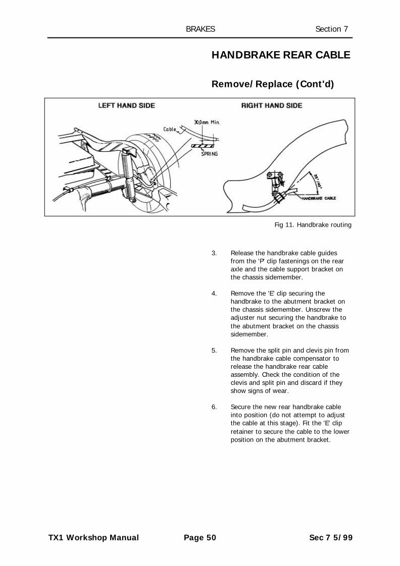
Fig 11. Handbrake routing
3. Release the handbrake cable guidesfrom the 'P' clip fastenings on the rearaxle and the cable support bracket onthe chassis sidemember.
4. Remove the 'E' clip securing thehandbrake to the abutment bracket onthe chassis sidemember. Unscrew theadjuster nut securing the handbrake tothe abutment bracket on the chassissidemember.
5. Remove the split pin and clevis pin fromthe handbrake cable compensator torelease the handbrake rear cableassembly. Check the condition of theclevis and split pin and discard if theyshow signs of wear.
6. Secure the new rear handbrake cableinto position (do not attempt to adjustthe cable at this stage). Fit the 'E' clipretainer to secure the cable to the lowerposition on the abutment bracket.

BRAKES Section 7
TX1 Workshop Manual Page 51 Sec 7 5/99
HANDBRAKE REAR CABLE
Remove/Replace (Cont'd)
NOTE: The new hand brake cable is fitted sothat the threaded adjuster is mounted into thetop position on the abutment bracket on thechassis side member with an adjuster nut eachside of the bracket. Remove the adjuster nutsfrom the threaded portion of the cable beforeattempting to fit it to the vehicle.
7. Route the handbrake cable from itsupper position on the handbrakeabutment bracket, behind the left handrear damper through to the left handrear brake backplate as shown in Fig.10. Secure the cable into position at thetop location on the cable supportbracket (on the chassis sidemember)and the two locations on the rear axleusing the 'P' clips and hardware fittedpreviously. Torque the 'P' clip bolts to10 - 14 Nm (7.5-9.5 lbf. ft.).
NOTE: The 'P' clip fitted to the outer positionon the axle may differ from that fitted at theother two locations.
Route the handbrake cable to the right handbrake backplate, attaching it to the lowermounting bolt of the cable support bracket (onthe chassis sidemember) as shown in Fig 10.Torque the bolt to 10 - 14 Nm (7.5 – 9.5 lbf.ft.).
8. Push the cable ends through the brakeback plates and reinstall the rear brakeshoes, connecting the brake cable to thebrake linkage, ensuring the new cable iscorrectly clipped into position on eachbackplate using new clips as required.
NOTE: Before performing the above operationcheck the condition of the rear brake liningsand drums. A new handbrake cable will notcompensate for worn out brake linings ordrums which must be replaced if their wearlimit has been reached.
BRAKES Section 7
TX1 Workshop Manual Page 52 Sec 7 5/99
HANDBRAKE REAR CABLE
Remove/Replace (Cont'd)
9. Lightly grease the brake drum spigotsand replace the brake drums and theirsecuring screws.
10. Connect the rear handbrake cablecompensator to the front handbrakecable and then the front handbrakecable to the handbrake lever using newclevis pins and split pins as required.Operate the brake pedal to align thebrake shoes.
11 . Adjust the rear hand brake cable usingthe cable adjusting nuts each side of thechassis abutment bracket to take up theslack in the rear cable until thehandbrake is fully 'on' with 5 'notches'of the handbrake lever. Operate thehandbrake several times to 'bed' thenew cable. Again check the adjustment(no load on the clevis pin). Lock up theadjusting nuts on the handbrake rearcable.
NOTE: Correctly adjusted, there should be nopre-load in the handbrake cables and will be4/5 “notches” on the handbrake lever ratchetbefore the handbrake is on.
12. Again check the handbrake operation,brake cable 'run' and the clevis and splitpins are secure.
13. Refit the road wheels tightening thesecuring nuts as much as possible.
14. Lower the vehicle and torque the wheelnuts to specification (torque 200 Nm,150 lb ft). Replace the hub caps.

BRAKES Section 7
TX1 Workshop Manual Page 53 Sec 7 5/99
HANDBRAKE FRONTCABLE
Remove/Replace
1. Release the handbrake and raise thevehicle on a lift Chock the wheels.
2. Remove the split pins and clevis pinssecuring the cable to the handbrakeshaft lever and the rear cablecompensator. Remove the 'E' clipssecuring the handbrake cable to thechassis abutment brackets and removethe cable.
3. Install the new cable noting that theyoke end is fitted towards thehandbrake lever. Ensure the 'E' clips arein good condition and fit into thegrooves machined into the handbrakeend fittings.
4. Check the condition of the clevis pinsand fit new as necessary. Connect thehandbrake cable to the compensatorfirst, followed by connection to thehandbrake lever. Fit new split pins.Operate the handbrake several timesand adjust the rear handbrake severaltimes and adjust the rear handbrake asnecessary.
NOTE: Correctly adjusted, there should be nopre-load in the handbrake cables and will be4/5 'notches' on the handbrake lever ratchetbefore the handbrake is on.

BRAKES Section 7
TX1 Workshop Manual Page 54 Sec 7 5/99