
WORKSHOP 16 STIFFENED PLATE - FSB Online · Submit the model to MSC.Nastran for a linear static...
36
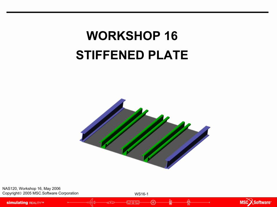
WS16-1 NAS120, Workshop 16, May 2006 Copyright© 2005 MSC.Software Corporation WORKSHOP 16 STIFFENED PLATE
Transcript of WORKSHOP 16 STIFFENED PLATE - FSB Online · Submit the model to MSC.Nastran for a linear static...
WS16-1NAS120, Workshop 16, May 2006Copyright© 2005 MSC.Software Corporation
WORKSHOP 16STIFFENED PLATE

WS16-2NAS120, Workshop 16, May 2006Copyright© 2005 MSC.Software Corporation

WS16-3NAS120, Workshop 16, May 2006Copyright© 2005 MSC.Software Corporation
Workshop ObjectivesPractice modeling a stiffened plate.
WS16-4NAS120, Workshop 16, May 2006Copyright© 2005 MSC.Software Corporation
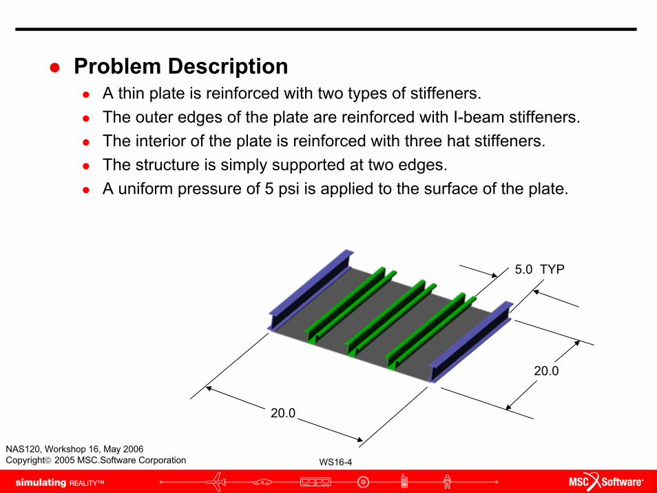
Problem DescriptionA thin plate is reinforced with two types of stiffeners.The outer edges of the plate are reinforced with I-beam stiffeners.The interior of the plate is reinforced with three hat stiffeners.The structure is simply supported at two edges.A uniform pressure of 5 psi is applied to the surface of the plate.
20.0
5.0 TYP
20.0

WS16-5NAS120, Workshop 16, May 2006Copyright© 2005 MSC.Software Corporation
Problem Description (cont.)The plate and stiffeners are constructed from aluminum alloy 7075-T73 with the following properties:
E = 10 x 106 psi
ν = 0.3
The plate is 0.100 in thick.

WS16-6NAS120, Workshop 16, May 2006Copyright© 2005 MSC.Software Corporation
Problem Description (cont.)The I-beam stiffener has the following cross section:
2.0
1.0
0.1 TYP

WS16-7NAS120, Workshop 16, May 2006Copyright© 2005 MSC.Software Corporation
Problem Description (cont.)The rolled hat stiffener has the following cross section:
B B
A
A
2.0
1.0
0.898
0.785
Cross-Sectional Area
0.504 in2
IAA 0.143 in4
IBB 0.174 in4
J 0.0016 in4
WS16-8NAS120, Workshop 16, May 2006Copyright© 2005 MSC.Software Corporation
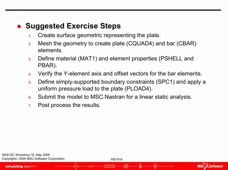
Suggested Exercise Steps1. Create surface geometric representing the plate.2. Mesh the geometry to create plate (CQUAD4) and bar (CBAR)
elements.3. Define material (MAT1) and element properties (PSHELL and
PBAR).4. Verify the Y-element axis and offset vectors for the bar elements.5. Define simply-supported boundary constraints (SPC1) and apply a
uniform pressure load to the plate (PLOAD4).6. Submit the model to MSC.Nastran for a linear static analysis.7. Post process the results.
WS16-9NAS120, Workshop 16, May 2006Copyright© 2005 MSC.Software Corporation
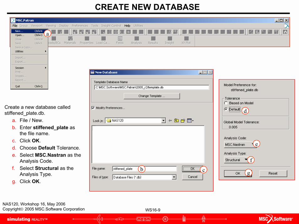
CREATE NEW DATABASE
Create a new database called stiffened_plate.db.
a. File / New.b. Enter stiffened_plate as
the file name.c. Click OK.d. Choose Default Tolerance.e. Select MSC.Nastran as the
Analysis Code.f. Select Structural as the
Analysis Type. g. Click OK.
a
b c
d
e
f
g

WS16-10NAS120, Workshop 16, May 2006Copyright© 2005 MSC.Software Corporation
Step 1. Geometry: Create / Surface / XYZ
Create the surface.a. Geometry: Create /
Surface / XYZ.b. Enter <20 20 0> for the
Vector Coordinate List.c. Click Apply.
a
b
c

WS16-11NAS120, Workshop 16, May 2006Copyright© 2005 MSC.Software Corporation
Step 1. Geometry: Create / Curve / XYZ
Turn on the Show Parametric Direction feature.
a. Display / Geometry...b. Check the Show
Parametric Directionbox.
c. Click Apply.d. Click Cancel.
b
c d
a

WS16-12NAS120, Workshop 16, May 2006Copyright© 2005 MSC.Software Corporation
Step 1. Geometry: Edit / Surface / Break
Break the surface in the u-direction.
a. Geometry: Edit / Surface / Break.
b. Change the Option to Parametric.
c. Choose Constant u Direction as the Break Direction.
d. Enter 0.5 as the Break Curve value.
e. Screen pick the surface created earlier.
f. Answer Yes when the question “Do you wish to delete the original surfaces?” appears.
a
b
c
d
e
e
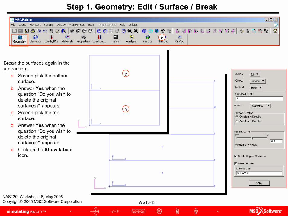
WS16-13NAS120, Workshop 16, May 2006Copyright© 2005 MSC.Software Corporation
Step 1. Geometry: Edit / Surface / Break
Break the surfaces again in the u-direction.
a. Screen pick the bottom surface.
b. Answer Yes when the question “Do you wish to delete the original surfaces?” appears.
c. Screen pick the top surface.
d. Answer Yes when the question “Do you wish to delete the original surfaces?” appears.
e. Click on the Show labelsicon.
e
c
a
WS16-14NAS120, Workshop 16, May 2006Copyright© 2005 MSC.Software Corporation
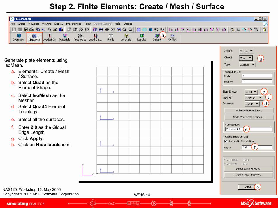
Step 2. Finite Elements: Create / Mesh / Surface
Generate plate elements using IsoMesh.
a. Elements: Create / Mesh / Surface.
b. Select Quad as the Element Shape.
c. Select IsoMesh as the Mesher.
d. Select Quad4 Element Topology.
e. Select all the surfaces.
f. Enter 2.0 as the Global Edge Length.
g. Click Apply.h. Click on Hide labels icon.
a
h
bc
g
d
e
f

WS16-15NAS120, Workshop 16, May 2006Copyright© 2005 MSC.Software Corporation
Step 2. Finite Elements: Create / Mesh / Curve
Generate bar elements along the longitudinal edges of the surfaces.
a. Elements: Create / Mesh / Curve.
b. Choose Bar2 as the element Topology.
c. Select 5 horizontal surface edges.
d. Click Apply.
a
b
c
d

WS16-16NAS120, Workshop 16, May 2006Copyright© 2005 MSC.Software Corporation
Step 2. Finite Element: Equivalence / All / Tolerance Cube
Equivalence the model nodes to connect elements along surface edges.
a. Elements: Equivalence / All / Tolerance Cube.
b. Click Apply.
a
b
WS16-17NAS120, Workshop 16, May 2006Copyright© 2005 MSC.Software Corporation
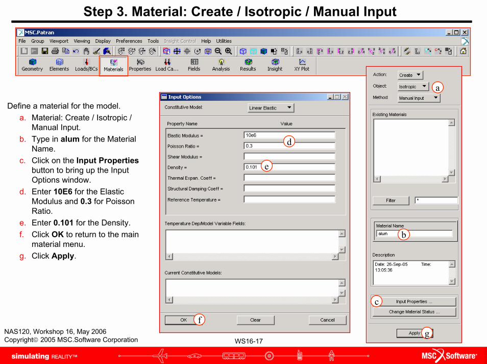
Step 3. Material: Create / Isotropic / Manual Input
Define a material for the model. a. Material: Create / Isotropic /
Manual Input. b. Type in alum for the Material
Name.c. Click on the Input Properties
button to bring up the Input Options window.
d. Enter 10E6 for the Elastic Modulus and 0.3 for Poisson Ratio.
e. Enter 0.101 for the Density.f. Click OK to return to the main
material menu. g. Click Apply.
d
e
f
a
b
g
c

WS16-18NAS120, Workshop 16, May 2006Copyright© 2005 MSC.Software Corporation
Step 3. Element Properties: Create / 2D / Shell
Create element properties for the plate elements.
a. Properties: Create / 2D / Shell.
b. Enter plate as the Property Set Name.
c. Click on the Input Propertiesbutton.
d. Click on the Matl Prop Nameicon.
e. Click on the alum in the Select Existing Material window.
f. Enter 0.1 as the thickness. g. Click OK.h. Select all surfaces for the
Application Region.i. Click Add. j. Click Apply.
d
f
e
g
a
b
c
hi
j

WS16-19NAS120, Workshop 16, May 2006Copyright© 2005 MSC.Software Corporation
Step 3. Element Properties: Create / 1D / Beam
Create element properties for the hat stiffeners.
a. Properties: Create / 1D / Beam.
b. Enter hat_stiffener as the Property Set Name.
c. Click on the Input Propertiesbutton.
d. Click on the Matl Prop Nameicon.
e. Click on alum in the Select Existing Material window.
f. Enter <0 0 1> for the Bar Orientation.
g. Enter <0 0 .948> for the offset at Node 1 and Node 2.
df
e
g
a
b
c
WS16-20NAS120, Workshop 16, May 2006Copyright© 2005 MSC.Software Corporation
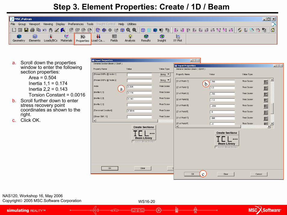
a
Step 3. Element Properties: Create / 1D / Beam
a. Scroll down the properties window to enter the following section properties:
Area = 0.504Inertia 1,1 = 0.174Inertia 2,2 = 0.143Torsion Constant = 0.0016
b. Scroll further down to enter stress recovery point coordinates as shown to the right.
c. Click OK.
b
c

WS16-21NAS120, Workshop 16, May 2006Copyright© 2005 MSC.Software Corporation
Step 3. Element Properties: Create / 1D / Beam
a. Click on Select Members, then click on the beam element filter.
b. For the application region select three rows of bar elements.
c. Click Add. d. Click Apply.
ac
d
a

WS16-22NAS120, Workshop 16, May 2006Copyright© 2005 MSC.Software Corporation
Step 3. Element Properties: Create / 1D / Beam
Next, create element properties for the I-beam stiffeners.
a. Properties: Create / 1D / Beam.
b. Enter i_stiffener as the Property Set Name.
c. Click on the Input Properties button.
d. Click on the Matl Prop Name icon.
e. Click on alum in Select Existing Material window.
f. Enter <0 0 1> for Bar Orientation.
g. Enter <0 0 1.05> for the Offset at both nodes.
h. Click on Beam Library icon.
df
g
e
h
a
b
c
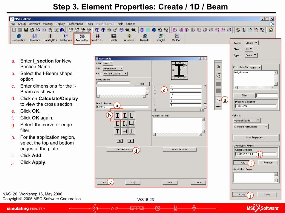
WS16-23NAS120, Workshop 16, May 2006Copyright© 2005 MSC.Software Corporation
Step 3. Element Properties: Create / 1D / Beam
a. Enter i_section for New Section Name.
b. Select the I-Beam shape option.
c. Enter dimensions for the I-Beam as shown.
d. Click on Calculate/Displayto view the cross section.
e. Click OK.f. Click OK again.g. Select the curve or edge
filter.h. For the application region,
select the top and bottom edges of the plate.
i. Click Add.j. Click Apply.
a
b
c
d
e
g
hi
j
WS16-24NAS120, Workshop 16, May 2006Copyright© 2005 MSC.Software Corporation
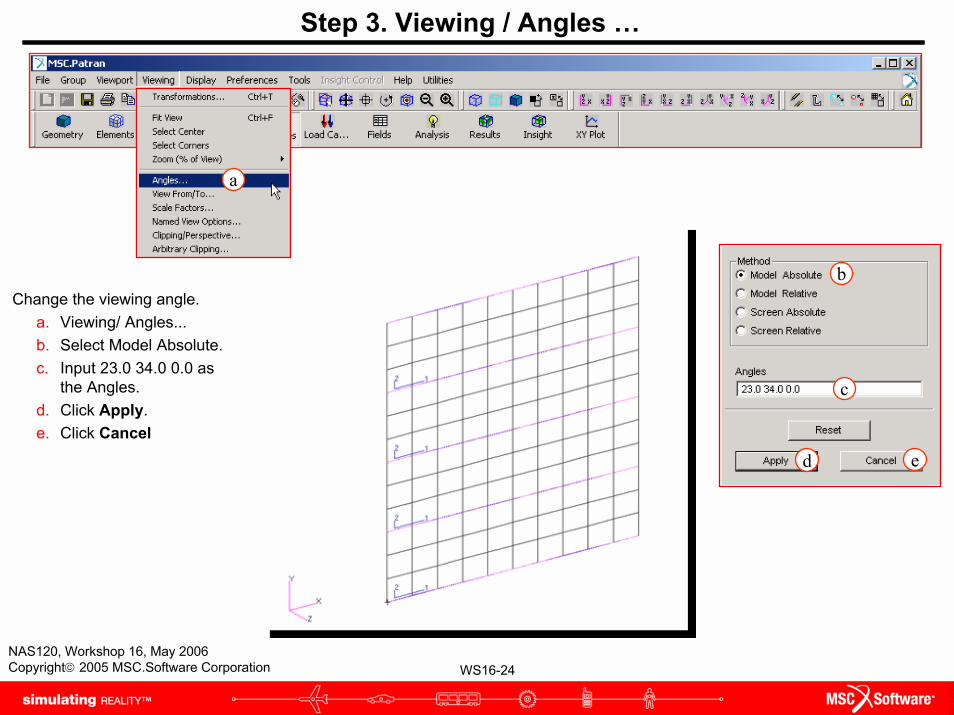
Step 3. Viewing / Angles …
Change the viewing angle.a. Viewing/ Angles... b. Select Model Absolute.c. Input 23.0 34.0 0.0 as
the Angles.d. Click Apply.e. Click Cancel
b
c
d e
a

WS16-25NAS120, Workshop 16, May 2006Copyright© 2005 MSC.Software Corporation
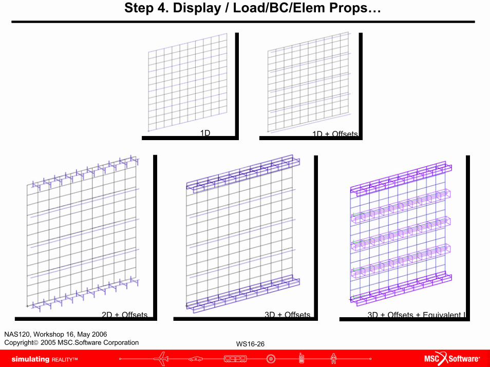
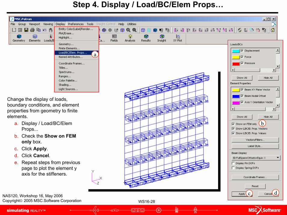
Step 4. Display / Load/BC/Elem Props…
Change the display settings to show beam offset.
a. Display / Load/BC/Elem Props... b. Change Beam Display from 1D line
to 1D line + offsets c. Click Apply.d. Change Beam Display to 2D Mid-
Span + Offsetse. Click Apply.f. Change Beam Display to 3D Full-
Span + Offsets.g. Change Beam Display to 3D Full-
Span + Offsets + Equivalent I.h. Click Apply.i. Click Cancel.
b
c
d
f
i
g
a
WS16-26NAS120, Workshop 16, May 2006Copyright© 2005 MSC.Software Corporation
Step 4. Display / Load/BC/Elem Props…
1D + Offsets
2D + Offsets 3D + Offsets
1D
3D + Offsets + Equivalent I
WS16-27NAS120, Workshop 16, May 2006Copyright© 2005 MSC.Software Corporation
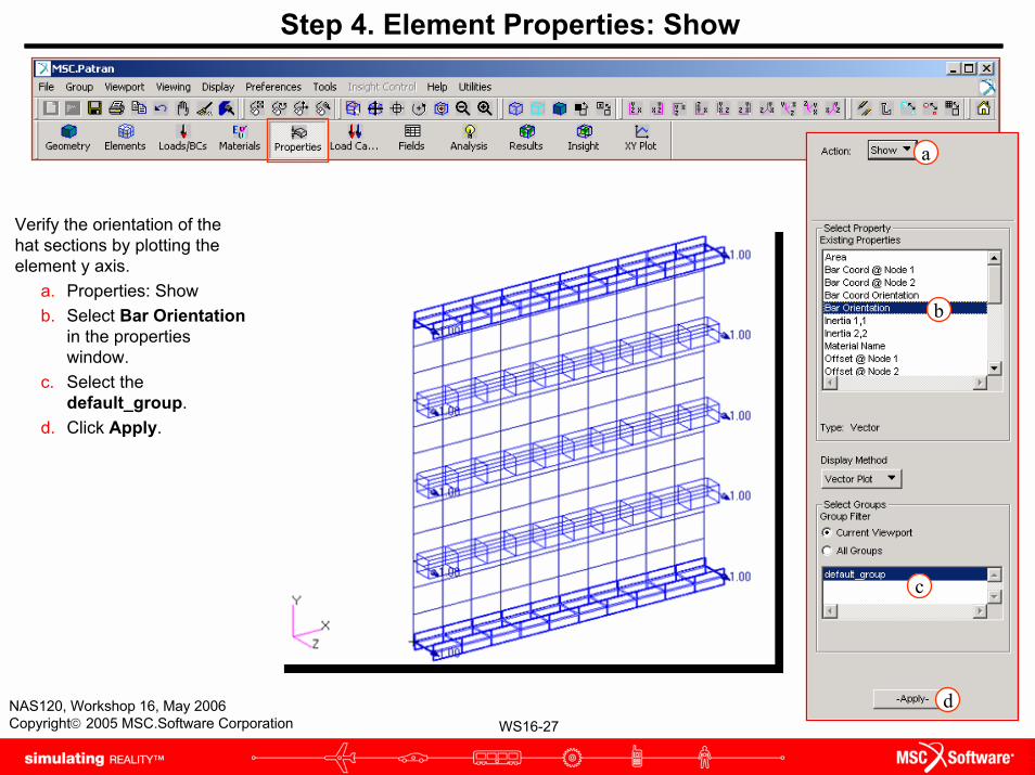
Step 4. Element Properties: Show
Verify the orientation of the hat sections by plotting the element y axis.
a. Properties: Showb. Select Bar Orientation
in the properties window.
c. Select the default_group.
d. Click Apply.
a
b
c
d
WS16-28NAS120, Workshop 16, May 2006Copyright© 2005 MSC.Software Corporation
Step 4. Display / Load/BC/Elem Props…
Change the display of loads, boundary conditions, and element properties from geometry to finite elements.
a. Display / Load/BC/Elem Props...
b. Check the Show on FEM only box.
c. Click Apply.d. Click Cancel.e. Repeat steps from previous
page to plot the element y axis for the stiffeners.
b
c d
a

WS16-29NAS120, Workshop 16, May 2006Copyright© 2005 MSC.Software Corporation
Step 5. Loads/BCs: Create / Displacement / Nodal
Create the boundary condition for the model.
a. Loads/BCs: Create / Displacement / Nodal.
b. Enter Simple_Support as the New Set Name.
c. Click on the Input Databutton.
d. Enter <0 0 0> for the Translations.
e. Click OK. f. Click on Select Application
Region. g. Select Geometry as the
geometry filter. h. Set the picking filter to Curve
or Edge.i. Select the left and right edges
of the plate.j. Click Add.k. Click OK. l. Click Apply.
d
e
g
h
i
j
k
a
b
cf
l

WS16-30NAS120, Workshop 16, May 2006Copyright© 2005 MSC.Software Corporation
Step 5. Loads/BCs: Create / Displacement / Nodal
Stiffened plate with two edges constrained.

WS16-31NAS120, Workshop 16, May 2006Copyright© 2005 MSC.Software Corporation
Step 5. Loads/BCs: Create / Pressure / Element Uniform
Apply pressure to the model.a. Loads/BCs: Create / Pressure
/ Element Uniform. b. Enter pressure as the New
Set Name.c. Select 2D as the Target
Element Type. d. Click on the Input Data
button.e. Enter 5 in the Top Surf
Pressure field. f. Click OK. g. Click on Select Application
Region button. h. Select Geometry as the
Geometry Filter. i. Set the picking filter to
Surface.j. Select all the surfaces for the
Application Region. k. Click Add, and OK. l. Click Apply.
e
f
h
i
j
k
a
b
c
dg
l
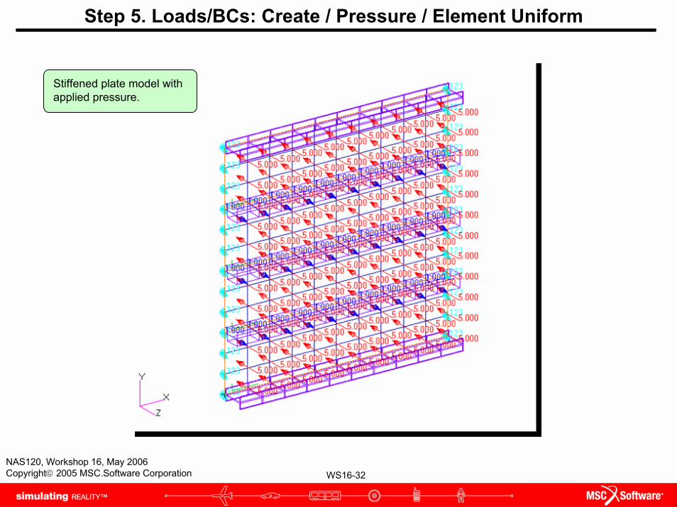
WS16-32NAS120, Workshop 16, May 2006Copyright© 2005 MSC.Software Corporation
Step 5. Loads/BCs: Create / Pressure / Element Uniform
Stiffened plate model with applied pressure.
WS16-33NAS120, Workshop 16, May 2006Copyright© 2005 MSC.Software Corporation
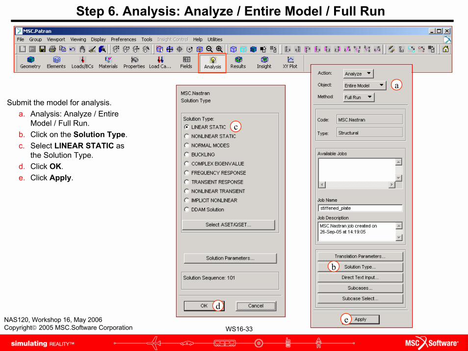
Step 6. Analysis: Analyze / Entire Model / Full Run
Submit the model for analysis. a. Analysis: Analyze / Entire
Model / Full Run. b. Click on the Solution Type. c. Select LINEAR STATIC as
the Solution Type. d. Click OK. e. Click Apply.
a
b
c
de

WS16-34NAS120, Workshop 16, May 2006Copyright© 2005 MSC.Software Corporation
Step 7. Analysis: Attach XDB / Result Entities / Local
After the job is completed, attach the XDB result file.
a. Access Results / Attach XDB / Result Entities.
b. Click on Select Result File. c. Select the file called
stiffened_plate.xdb. d. Click OK. e. Click Apply.
a
c
d
e
b
WS16-35NAS120, Workshop 16, May 2006Copyright© 2005 MSC.Software Corporation
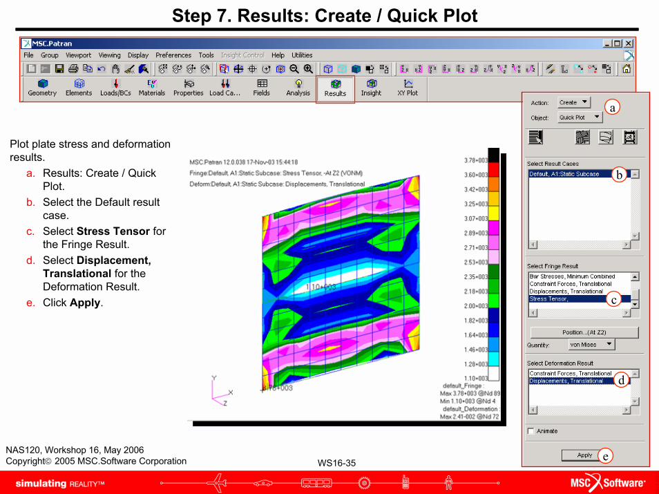
Step 7. Results: Create / Quick Plot
Plot plate stress and deformation results.
a. Results: Create / Quick Plot.
b. Select the Default result case.
c. Select Stress Tensor for the Fringe Result.
d. Select Displacement, Translational for the Deformation Result.
e. Click Apply.
a
b
c
d
e

WS16-36NAS120, Workshop 16, May 2006Copyright© 2005 MSC.Software Corporation
Step 7. Results: Create / Quick Plot
Plot bar stress results. a. Select Bar Stresses,
Maximum Combinedfor the Fringe Result.
b. Click Apply. c. Plot the remaining bar
stress components one at at time.
a
b
c


