Works Approval – Mining Area C South Flank · Tenure Mineral Leases ML281SA and ML249SA ... •...
66
Works Approval – Mining Area C South Flank Supporting Documentation (Including Information relating to Attachments 1 to 8) March 2018 Jimblebar L5415/1988/9 Licence Amendment Supporting Documentation (Including Information relating to Attachments 1 to 10) October 2017
-
Upload
truongcong -
Category
Documents
-
view
214 -
download
0
Transcript of Works Approval – Mining Area C South Flank · Tenure Mineral Leases ML281SA and ML249SA ... •...

Works Approval – MiningArea C South FlankSupporting Documentation (Including Informationrelating to Attachments 1 to 8)
March 2018
JimblebarL5415/1988/9Licence Amendment SupportingDocumentation(Including Information relating to Attachments 1 to 10)
October 2017
Works Approval – Mining Area C South Flank
i
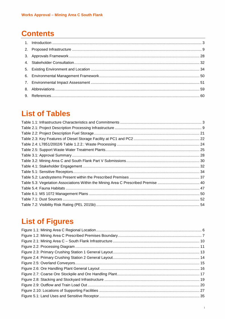
Contents1. Introduction ............................................................................................................................................... 3
2. Proposed Infrastructure ............................................................................................................................ 9
3. Approvals Framework ............................................................................................................................. 28
4. Stakeholder Consultation........................................................................................................................ 32
5. Existing Environment and Location ........................................................................................................ 34
6. Environmental Management Framework................................................................................................ 50
7. Environmental Impact Assessment ........................................................................................................ 51
8. Abbreviations .......................................................................................................................................... 59
9. References.............................................................................................................................................. 60
List of TablesTable 1.1: Infrastructure Characteristics and Commitments .............................................................................. 3Table 2.1: Project Description Processing Infrastructure ................................................................................... 9Table 2.2: Project Description Fuel Storage..................................................................................................... 21Table 2.3: Key Features of Diesel Storage Facility at PC1 and PC2 ............................................................... 22Table 2.4: L7851/2002/6 Table 1.2.2.: Waste Processing ............................................................................... 24Table 2.5: Support Waste Water Treatment Plants.......................................................................................... 25Table 3.1: Approval Summary .......................................................................................................................... 28Table 3.2: Mining Area C and South Flank Part V Submissions...................................................................... 30Table 4.1: Stakeholder Engagement ................................................................................................................ 32Table 5.1: Sensitive Receptors......................................................................................................................... 34Table 5.2: Landsystems Present within the Prescribed Premises ................................................................... 37Table 5.3: Vegetation Associations Within the Mining Area C Prescribed Premise ........................................ 40Table 5.4: Fauna Habitats ................................................................................................................................ 47Table 6.1: MS 1072 Management Plans .......................................................................................................... 50Table 7.1: Dust Sources ................................................................................................................................... 52Table 7.2: Visibility Risk Rating (PEL 2015b) ................................................................................................... 54
List of FiguresFigure 1.1: Mining Area C Regional Location..................................................................................................... 6Figure 1.2: Mining Area C Prescribed Premises Boundary................................................................................ 7Figure 2.1: Mining Area C – South Flank Infrastructure ................................................................................... 10Figure 2.2: Processing Diagram ....................................................................................................................... 11Figure 2.3: Primary Crushing Station 1 General Layout................................................................................... 13Figure 2.4: Primary Crushing Station 2 General Layout................................................................................... 14Figure 2.5: Overland Conveyors....................................................................................................................... 15Figure 2.6: Ore Handling Plant General Layout ............................................................................................... 16Figure 2.7: Coarse Ore Stockpile and Ore Handling Plant............................................................................... 17Figure 2.8: Stacking and Stockyard Infrastructure ........................................................................................... 19Figure 2.9: Outflow and Train Load Out ........................................................................................................... 20Figure 2.10: Locations of Supporting Facilities ................................................................................................ 27Figure 5.1: Land Uses and Sensitive Receptor ................................................................................................ 35

ii
AttachmentsAttachment 0: Compliance Report Project Characteristics and Commitments ConfirmationAttachment 1: Applicants DetailsAttachment 1a Proof of occupier statusAttachment 1B: ASIC company extractsAttachment 2A: Premises, Facilities and Location MapAttachment 2B: Prescribed Premises Map CoordinatesAttachment 3A: Proposed ActivitiesAttachment 4A: Other Approvals MS1072Attachment 4B: Other Approvals: Environmental Licence L7851/2002/6Attachment 5: Emissions and discharges and Waste acceptanceAttachment 6: Siting and locationAttachment 7A: Supporting Document – Dust ModellingAttachment 7B: Supporting Document – Risk Summary

Works Approval – Mining Area C South Flank
Page | 3
1. Introduction1.1. Background
BHP Billiton Iron Ore Pty Ltd (BHP) currently operates a number of Iron Ore mines and associated rail and portinfrastructure within the Pilbara region of Western Australia (WA). Current mining operations include the:
· Newman Joint Venture (NJV) hub located approximately two kilometres (km) west of Newman Townshipand consists of Mount Whaleback, and Orebodies 29, 30 and 35;
· Mining Area C located approximately 90 km north west of Newman Township;
· Wheelarra Hill (Jimblebar) Mine, Orebody 18 and Orebody 31 (Jimblebar Hub) are located approximately35 km east of Newman Township;
· Eastern Ridge hub located approximately 5 km east of Newman Township and consists of Orebodies 23,24, 25 and 32; and
· Yandi Mine located approximately 100 km north-west of Newman Township.
Ore from the NJV hub, Mining Area C, Eastern Ridge, Wheelarra Hill (Jimblebar) and Yandi mining operationsis transported to Port Hedland via the BHP Billiton Newman to Port Hedland Mainline (and associated spurlines). Ore is then shipped out through Port Hedland at the BHP facilities at Nelson Point and Finucane Island.
1.2. Purpose of this Document
BHP currently operates an iron ore mine at Mining Area C, under environmental licence L7851/2002/6. BHPis seeking to develop and operate a satellite ore body at South Flank by submission of works approval to:
· Construct Category 5, 80 million tonnes per annum (Mtpa) processing facility, two 40Mtpa primary crushingstations and conveyors;
· Construct Category 73, two 2ML diesel storage facilities: and
· Request staged commissioning of the above facilities.
This supporting document has been prepared to provide supplementary information to the “Application Form:Works Approval / Licence / Renewal / Amendment / Registration” for the South Flank works approval, asrequired under Section 54 of the Environmental Protection Act 1986 (EP Act).
BHP commits to undertake the proposed works in accordance with the details set out in Table 1.1. BHP willconfirm compliance as detailed in Table 1.1 in the compliance document using the template provided(Attachment 0). Compliance reporting will be required to be submitted in stages to meet the construction andcommissioning requirements, at the completion of construction and prior to commencement of loadcommissioning of the infrastructure. BHP will communicate the change to the Department of Water andEnvironmental Regulation and detail the change in the Compliance Report.
Table 1.1: Infrastructure Characteristics and Commitments
Infrastructure Characteristics
Infrastructure: Category 5 Processing or beneficiation of metallic or non-metallic ore
Two primary crushing stations
Overland conveyors
Transfer stations
Ore Handling Plant
Category 73 Bulk Fuel Storage
Two diesel storage facilites

Works Approval – Mining Area C South Flank
4
Maximum production /design capacity
Primary crushing stations - 40Mtpa each
Ore handling Plant 80Mtpa
Diesel Storage 2ML (2,000kL) each facility
Location of all infrastructureassociated with the WorksApproval:
Mining Area C prescribed premise (see Figure 1.2 and Attachment 0)
Tenure Mineral Leases ML281SA and ML249SA
Commissioning andCompliance Report:
A two year load commissioning period is required.
BHP commits to undertake the proposed works in accordance with the details set outin Table 1.1. BHP will confirm compliance as detailed in Table 1.1 in the compliancedocument using the template provided (Attachment 0). Compliance reporting will berequired to be submitted in stages to meet the construction and commissioningrequirements.
Licence: The infrastructure will be operated under the existing Environmental Operating LicenceL7851/2002/6.
Relevant EnvironmentalFactors:
The following environmental factors associated with the proposed infrastructure areconsidered to require management measures as detailed below:
· Air Quality – Dust
· Treated Waste Water
· Surface Water
Application Commitments Phase to which theCommitment Applies1
Section
BHP will confirm compliance with phase commitments. Commissioning 2.4 and 2.5
Compliance reporting will be required to be submitted in stages tomeet the construction and commissioning requirements. (asdetailed in Table 1 using the template provided Attachment 0) willbe submitted and a Licence amendment obtained from, theDWER.
Commissioning 2.4 and 2.5
BHP will communicate the change to the Department of Waterand Environmental Regulation and detail the change in theCompliance Report.
Construction andCommissioning
2.4
Dust emissions will be managed through the
· Automated dust suppression water cannons,
· fogging systems will be located on the ROM Bin, productscreening, scalping and crushing buildings at discharge fromscreens and crushers;
· Covers and/or hoods installed in PC1, PC2 and OHP3;
· Bulk Ore Conditioning (BOC) sprays and moisture analysersalong the conveyors
Commissioning and Operations 2.1 and 7.1.1
Works Approval – Mining Area C South Flank
5
Storm water from key infrastructure areas will be diverted througha sedimentation pond prior to discharge sedimentation ponds
All 7.1.1
Water potentially contaminated with hydrocarbons will be treatedby an oily water separator until monitoring confirms the Totalrecoverable hydrocarbons (TRH) concentration is less than15mg/L;
All 7.1.3
Fuel facilities will be managed through the
· The prevention of spills through the implementation ofengineering and administrative controls (Table 2.3);
· Facilities will be constructed in accordance with AustralianStandard 1940-2004 The storage and handling of flammableand combustible liquids;
· Stored and handled in accordance with the requirements ofthe Dangerous Goods Safety Act 2004; Dangerous GoodsSafety (Storage and Handling of non-explosives) Regulations2007; and Australian Standard 1940-2004;
· Spill kits will be provided and maintain at refueling points andfuel storage facilities
Construction and commissioning 2.2 7.2
1 Please note that these commitments only apply to the Pre-construction, Construction and Commissioning phases ofthe project. Further commitments related to the Operation and Decommissioning of the infrastructure will be detailed insubsequent license application(s) to the Department of Environment Regulation (DWER)
1.3. Premises
1.3.1. Location
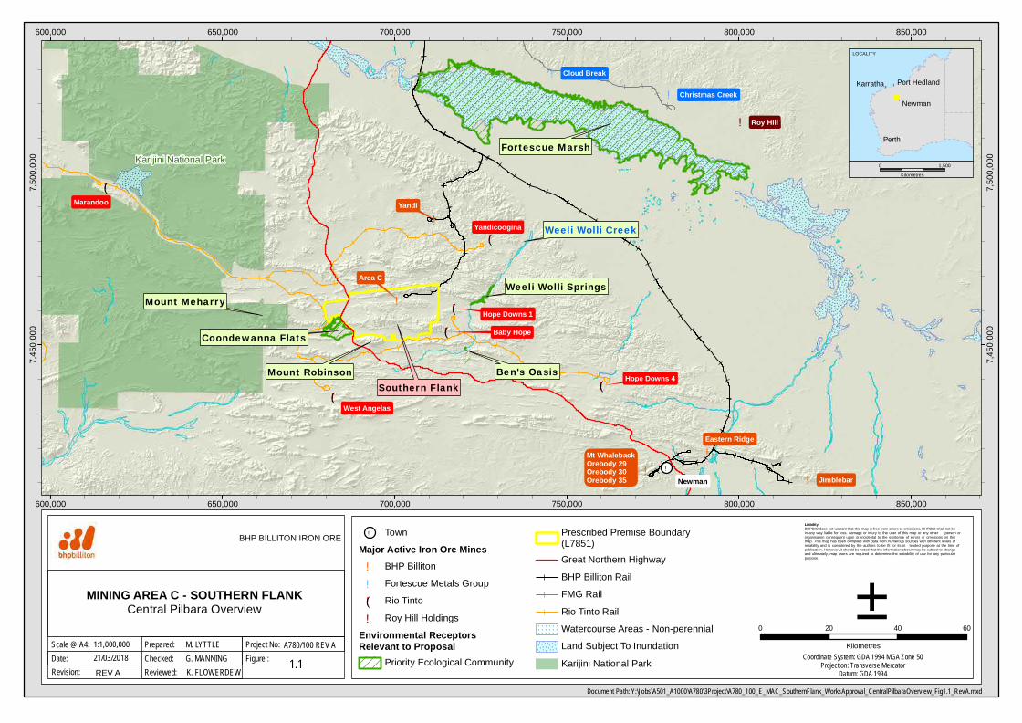
The Mining Area C is located approximately 90 km northwest of the Newman Township in the Pilbara region ofWestern Australia (Figure 1.1). The South Flank ore body is positioned approximately 8 km south of BHPMining Area C (Figure 1.1).
1.3.2. Tenement Details
The proposed infrastructure is located primarily on Mineral Leases ML281SA and ML249SA and are subject tothe Iron Ore (Mount Goldsworthy) Agreement Act 1964 State Agreement legislation (Attachment 1.
1.3.3. Local Government
Mining Area C is located within the Shire of East Pilbara.
1.3.4.Prescribed Premise Boundary
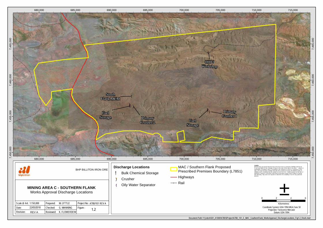
An application has been submitted (31 Jan 2018) to expand the prescribed premise boundary to include theSouth Flank Satellite deposit and associated infrastructure (Figure 1.2). The proposed boundary will align withthe proposed Ministerial Statement boundary with the exception of the rail corridor and the south-eastern cornerthat overlies Rio Tinto’s rail corridor. The spatial coordinates of the prescribed premise are included in(Attachment 2). Figure 1.2shows the approximate locations of the proposed discharge points within theprescribed premises.
!(
!!
!(
!
!
!
!(
!
!(
!(
!
!
!
Southern Flank
Fortescue Marsh
Coondewanna Flats
Mount Robinson
Weeli Wolli Springs
Marandoo
Ben's Oasis
Baby Hope
Mount Meharry
Weeli Wolli Creek
!(
Area C
Yandi
Mt WhalebackOrebody 29Orebody 30Orebody 35
Eastern Ridge
Jimblebar
Cloud Break
Christmas Creek
Hope Downs 1
Hope Downs 4
Yandicoogina
West Angelas
Roy Hill
Newman
Karijini National Park
600,000
600,000
650,000
650,000
700,000
700,000
750,000
750,000
800,000
800,000
850,000
850,000
7,450
,000
7,450
,000
7,500
,000
7,500
,000
Liability BHPBIO does not warrant that this map is free from errors or omissions. BHPBIO shall not be in any way liable for loss, damage or injury to the user of this map or any other person or organisation consequent upon or incidental to the existence of errors or omissions on this map. This map has been compiled with data from numerous sources with different levels of reliability and is considered by the authors to be fit for its in tended purpose at the time of publication. However, it should be noted that the information shown may be subject to change and ultimately, map users are required to determine the suitability of use for any particular purpose.
Document Path: Y:\Jobs\A501_A1000\A780\3Project\A780_100_E_MAC_SouthernFlank_WorksApproval_CentralPilbaraOverview_Fig1.1_RevA.mxd
Date:Scale @ A4:
MINING AREA C - SOUTHERN FLANK Central Pilbara Overview
0 20 40 60
Kilometres
1.1
±21/03/2018
BHP BILLITON IRON ORE
Figure :Project No:1:1,000,000
Checked:Prepared: M. LYTTLE
G. MANNINGA780/100 REV A
Revision: REV A Reviewed: K. FLOWERDEWCoordinate System: GDA 1994 MGA Zone 50
Projection: Transverse MercatorDatum: GDA 1994
! TownMajor Active Iron Ore Mines! BHP Billiton! Fortescue Metals Group!( Rio Tinto! Roy Hill Holdings
Environmental ReceptorsRelevant to Proposal
Priority Ecological Community
Prescribed Premise Boundary(L7851)Great Northern HighwayBHP Billiton RailFMG RailRio Tinto RailWatercourse Areas - Non-perennialLand Subject To InundationKarijini National Park
!
!
!
!
Newman
Karratha
Perth
Port Hedland
LOCALITY
0 1,500Kilometres
!!
!(
!(
!(
!(
")
") PrimaryCrusher 1Primary
Crusher 2
SouthFlank MEM
OHP3Workshop
FuelStorage Fuel
Storage
680,000
680,000
685,000
685,000
690,000
690,000
695,000
695,000
700,000
700,000
705,000
705,000
710,000
710,000
715,000
715,0007,450
,000
7,450
,000
7,455
,000
7,455
,000
7,460
,000
7,460
,000
7,465
,000
7,465
,000
Liability BHPBIO does not warrant that this map is free from errors or omissions. BHPBIO shall not be in any way liable for loss, damage or injury to the user of this map or any other person or organisation consequent upon or incidental to the existence of errors or omissions on this map. This map has been compiled with data from numerous sources with different levels of reliability and is considered by the authors to be fit for its in tended purpose at the time of publication. However, it should be noted that the information shown may be subject to change and ultimately, map users are required to determine the suitability of use for any particular purpose.
Document Path: Y:\Jobs\A501_A1000\A780\3Project\A780_101_E_MAC_SouthernFlank_WorksApproval_DischargeLocations_Fig1.2_RevA.mxd
Date:Scale @ A4:
MINING AREA C - SOUTHERN FLANKWorks Approval Discharge Locations
0 2 4 6
Kilometres
1.2
±22/03/2018
BHP BILLITON IRON ORE
Figure :Project No:1:150,000
Checked:Prepared: M. LYTTLE
G. MANNINGA780/101 REV A
Revision: REV A Reviewed: K. FLOWERDEWCoordinate System: GDA 1994 MGA Zone 50
Projection: Transverse MercatorDatum: GDA 1994
Discharge Locations! Bulk Chemical Storage") Crusher!( Oily Water Separator
MAC / Southern Flank ProposedPrescribed Premises Boundary (L7851)HighwaysRail
Works Approval – Mining Area C South Flank
Page | 8
1.4. Proponent
BHP as the manager for the Mount Goldsworthy Mining Associates Joint Venture, which owns Mining Area Cincluding South Flank, has submitted this Works Approval application. The allocation between the partners ofthe Joint Venture is as follows:
§ BHP Billiton Minerals Pty Ltd 85%§ Itochu Minerals and Energy Australia Pty Ltd 8%§ Mitsui Iron Ore Corporation Pty Ltd 7%
BHP has the authority to act for the Mount Goldsworthy Joint Venture and is authorised as the manager andagent of the proponent to submit this application and execute the works as approved.
The key contact for this proposal is:Kimberley FlowerdewSpecialist – Environment A&IBHP BillitonPhone: (08) 6321 2078Email: [email protected] 36, 125 St Georges TerracePerth WA 6000 Australia
Works Approval – Mining Area C South Flank
Page | 9
2. Proposed Infrastructure2.1. Category 5 Process Infrastructure
2.1.1.Overview
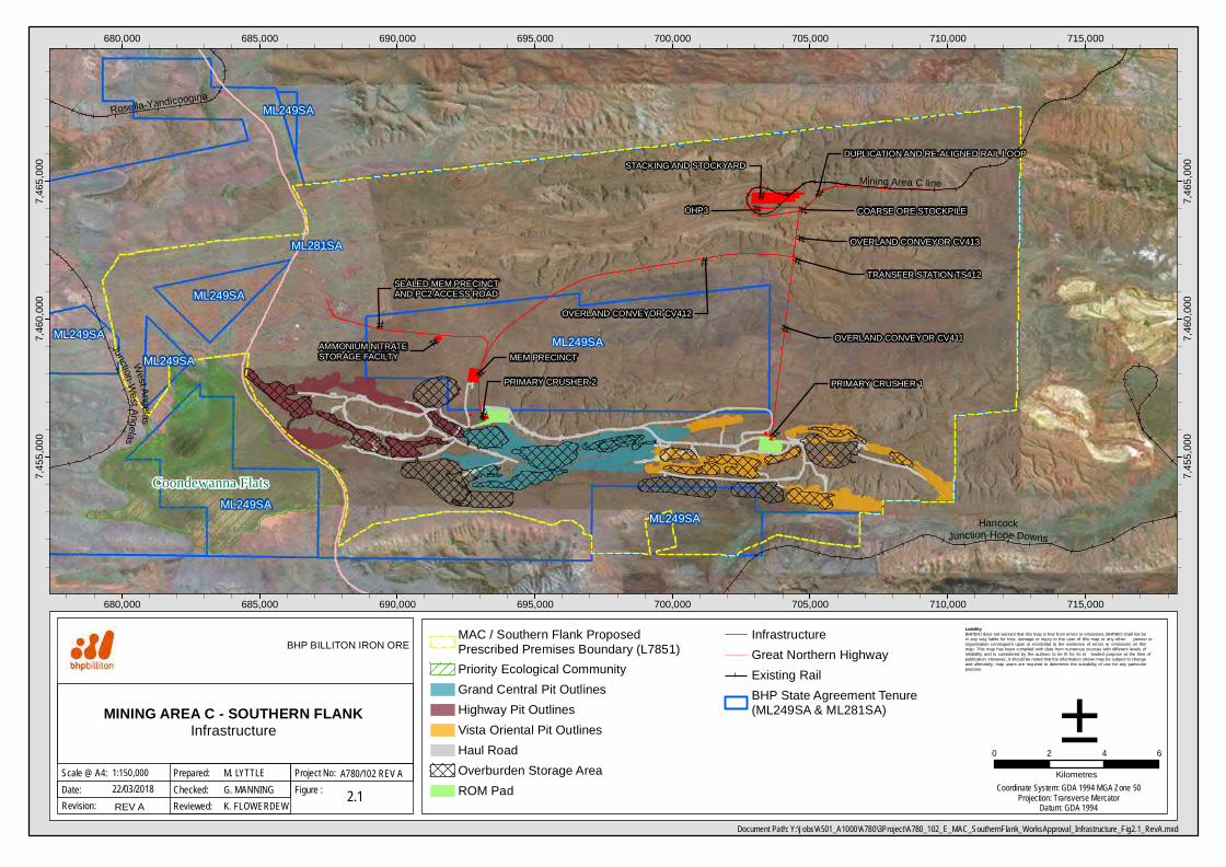
Mining at South Flank will be undertaken utilising conventional open-cut mining for iron ore. Campaign mininginvolves drilling, blasting, and categorisation of blasted material into iron ore or waste rock. Iron ore will beextracted from the three South Flank deposits - Highway, Vista Oriental and Grand Central (Figure 2.1).
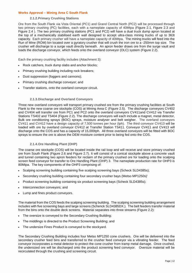
BHP is seeking a works approval to construct processing and support infrastructure at Mining Area C -SouthFlank (Table 2.1). Primary crushing will occur at South Flank, and overland conveyors will transport crushedore to the Mining Area C hub (Figure 2.1). The existing Mining Area C hub infrastructure and facilities will beexpanded with a a new ore handling plant (OHP) to achieve a nominal combined processing rate of 150 Mtpaof blended ore. Figure 2.2 illustrates the ore movement from the South Flank Deposits through the stages ofprocessing to the train load out facility.
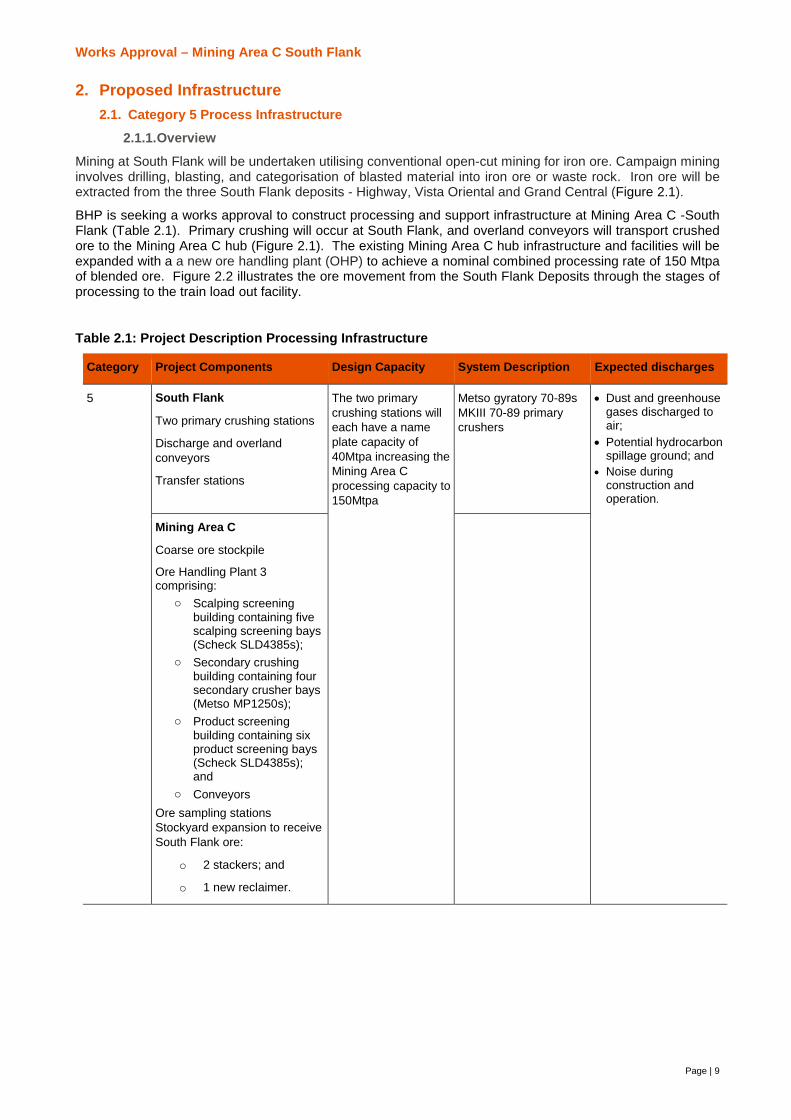
Table 2.1: Project Description Processing Infrastructure
Category Project Components Design Capacity System Description Expected discharges
5 South Flank
Two primary crushing stations
Discharge and overlandconveyors
Transfer stations
The two primarycrushing stations willeach have a nameplate capacity of40Mtpa increasing theMining Area Cprocessing capacity to150Mtpa
Metso gyratory 70-89sMKIII 70-89 primarycrushers
· Dust and greenhousegases discharged toair;
· Potential hydrocarbonspillage ground; and
· Noise duringconstruction andoperation.
Mining Area C
Coarse ore stockpile
Ore Handling Plant 3comprising:
o Scalping screeningbuilding containing fivescalping screening bays(Scheck SLD4385s);
o Secondary crushingbuilding containing foursecondary crusher bays(Metso MP1250s);
o Product screeningbuilding containing sixproduct screening bays(Scheck SLD4385s);and
o ConveyorsOre sampling stationsStockyard expansion to receiveSouth Flank ore:
o 2 stackers; and
o 1 new reclaimer.
Coondewanna Flats
# OVERLAND CONVEYOR CV413
#
OVERLAND CONVEYOR CV412
#
PRIMARY CRUSHER 1
#
PRIMARY CRUSHER 2
#
TRANSFER STATION TS412
#
MEM PRECINCT
#AMMONIUM NITRATESTORAGE FACILTY
#
SEALED MEM PRECINCT AND PC2 ACCESS ROAD
# COARSE ORE STOCKPILE
#
OHP3
#
STACKING AND STOCKYARD
# OVERLAND CONVEYOR CV411
#
DUPLICATION AND RE-ALIGNED RAIL LOOP
Rosella-Yandicoogina
WestAngelas
Junction-West Angelas
Mining Area C line
HancockJunction-Hope Downs
ML249SA
ML249SAML249SA
ML249SA
ML249SAML249SA
ML249SA
ML281SA
680,000
680,000
685,000
685,000
690,000
690,000
695,000
695,000
700,000
700,000
705,000
705,000
710,000
710,000
715,000
715,000
7,455
,000
7,455
,000
7,460
,000
7,460
,000
7,465
,000
7,465
,000
Liability BHPBIO does not warrant that this map is free from errors or omissions. BHPBIO shall not be in any way liable for loss, damage or injury to the user of this map or any other person or organisation consequent upon or incidental to the existence of errors or omissions on this map. This map has been compiled with data from numerous sources with different levels of reliability and is considered by the authors to be fit for its in tended purpose at the time of publication. However, it should be noted that the information shown may be subject to change and ultimately, map users are required to determine the suitability of use for any particular purpose.
Document Path: Y:\Jobs\A501_A1000\A780\3Project\A780_102_E_MAC_SouthernFlank_WorksApproval_Infrastructure_Fig2.1_RevA.mxd
Date:Scale @ A4:
MINING AREA C - SOUTHERN FLANKInfrastructure
0 2 4 6
Kilometres
2.1
±22/03/2018
BHP BILLITON IRON ORE
Figure :Project No:1:150,000
Checked:Prepared: M. LYTTLE
G. MANNINGA780/102 REV A
Revision: REV A Reviewed: K. FLOWERDEWCoordinate System: GDA 1994 MGA Zone 50
Projection: Transverse MercatorDatum: GDA 1994
MAC / Southern Flank ProposedPrescribed Premises Boundary (L7851)Priority Ecological CommunityGrand Central Pit OutlinesHighway Pit OutlinesVista Oriental Pit OutlinesHaul RoadOverburden Storage AreaROM Pad
InfrastructureGreat Northern HighwayExisting RailBHP State Agreement Tenure(ML249SA & ML281SA)

5632
5632
RECLAIMERRC02
LUMP 200,000t
BOC
MAGNETMA402
CV402
MISTING
BOC
PRIMARYCRUSHER
CR401
PRIMARY CRUSHINGBUILDING - PC1
BG401
WEIGHTOMETER BW434CV434
ROCKBREAKER
RB401
ROM BINBN401
APRONFEEDER AF403
BOC
OVERLAND CONVEYOR CV413
MAGNETMA405
METALDETECTOR
MD405CV405 COARSE ORE
STOCKPILE (COS)BG420
APRONFEEDERAF421
APRONFEEDERAF422
VENTILATIONFAN FA420
SURGE BINBN403
MISTING
PRIMARYCRUSHER
CR404
PRIMARY CRUSHINGBUILDING - PC2
BG404
ROCKBREAKER
RB404
ROM BINBN404
APRONFEEDER AF406
OLC CV412
BOCMOISTUREMN412
BOC
OLC CV411
BOC
WTR
FINES 440,000t
RECLAIMERRC01
CV521
BOC LPBOC
LPBOC
LPBOC LPBOC LPBOC LPBOC LPBOC
SHUTTLE SH435
BN453 BN452 BN451
GAI453 GAI452 GAI451
VF453 VF452 VF451
CV453 CV452 CV451
CR453 CR452 CR451
SECONDARYCONE CRUSHERS
CRUSHER FEED CONVEYORS
CRUSHERVIBRATING FEEDERS
ISOLATION GATES
SECONDARYCRUSHING FEED BINS
SECONDARY CRUSHING BUILDING (SCB) - BG450 TRANSFERSTATION TS439
CV439
CV435WEIGHTOMETERBW435B
WEIGHTOMETERBW439
SCALPING SCREENING BUILDING (SSB) - BG440WEIGHTOMETER BW471A
WEIGHTOMETER BW435A
WEIGHTOMETERBW436
TRAMPMAGNETMA435
MC314
ROW G
ROW F
STACKER ST04
FINES SAMPLESTATION SS497
BF471
FINES PRIMARYCUTTER SC471
CV474 LUMP
CV471 FINES
BN441 BN442 BN443
SCALPINGSCREENS
BELT FEEDERS
ISOLATIONGATES
SCALPING SCREENFEED BINS
GAI441 GAI442 GAI443
BF441 BF442 BF443
VS441 VS442 VS443
BN466
PRODUCTSCREENS
PRODUCT SCREENVIBRATING FEEDERS
ISOLATIONGATES
PRODUCT SCREENFEED BINS
GAI466
VF466
VS466
BN465
GAI465
VF465
VS465
BN464
GAI464
VF464
VS464
CV436SHUTTLE SH434
SHUTTLE SH436
FINES 440,000t
LUMP 200,000t LUMP 200,000t
PRODUCT SCREENING BUILDING (PSB) - BG460
LUMP PRODUCTSTACKER ST03
METAL DETECTORS MD453 MD452 MD451
31 January 2018
STOCKYARD 2 (SY2)
CV474 LUMP
CV471 FINES
BN454
GAI454
VF454
CV454
CR454
MD454
BN444
GAI444
BF444
VS444
BN445
GAI445
BF445
VS445
LPBOC
BN463
GAI463
VF463
VS463
BN462
GAI462
VF462
VS462
BN461
GAI461
VF461
VS461
LPBOC
ROW E
BOC
BOC
MC15
LUMP PRODUCTSTACKER ST01
MC11
MC08
LUMP128,000t
LUMP128,000t
LUMP128,000t
LUMP PRODUCTSTACKER ST02
STOCKYARD 1 (SY1)MC14
TRAIN LOADOUT 1
TRAIN LOADOUT 2BG522
BN09
BN522
MC304
MC303
LUMP MC302
MC315
FROM EXISTING PLANT(OHP1 & OHP2)
CV484
WEIGHTOMETERBW471B
WEIGHTOMETERBW474
LPBOC
BOC
CV472
LUMP SAMPLESTATION SS498
CV498
BF474
LUMP PRIMARYCUTTER SC474
BOC
CV475
CV494
MC309
WEIGHTOMETERWT521
MOISTUREMN521 BOC
WEIGHTOMETER WT301
WEIGHTOMETER WT302
BOC
BOC
BOC
BOC
BOC
BOC MC12
MC09
BOC
WEIGHTOMETER WT08
BOCMOISTURE
MM02
FINES MC301
CV476
CV484
ROW H
WEIGHTOMETERWT305
BOCMOISTURE
MM301
CV477
LUMP 197,000t
FINES / LUMP 594,000/561,000t (DEAD) FINES / LUMP 594,000/561,000t (DEAD)
MC308
LUMP 197,000t
LUMP 248,000t LUMP 248,000t
FINES 480,000t FINES 480,000tFINES 480,000t
RECLAIMERRC03
CV513
CV485
CV478
CV473
BOC
BOCBOC
BOC
BOC
BOC
ROW J
BOC
BOC
STACKER ST05
CV495FINES 480,000t
LUMP 248,000t
CV485
BELT PROFILEBP405
MATERIALSIZING ATS412 BOC
MATERIALSIZING ATS411
BELT PROFILEBP413
MOISTUREMN434
MATERIALSIZING ATS471A MATERIAL
SIZING ATS471B
MATERIALSIZING ATS474
METALDETECTOR
MD315 BOC
BELT PROFILEBP521 BOC
ELEMENTALATX484
MOISTUREMN472
ELEMENTALATX473
ELEMENTALATX476
MOISTUREMN411
METALDETECTOR
MD402BELT PROFILEBP402
MOISTUREMN475
BOCBOCBOC
SURGE BINBN406
BOC
BOC
BELT PROFILEBP412
BOC
BELT PROFILEBP411
BOCBOC BOCBOC
PC1 SURGE BINBUILDING - BG403
PC2 SURGE BINBUILDING - BG406
WEIGHTOMETER BW412 WEIGHTOMETER BW411
BOC
WATER DIVERTER WD413
WATER DIVERTER WD411MATERIAL DIVERSIONPLOUGH DVP411
MATERIAL DIVERSIONPLOUGH DVP434
MATERIAL DIVERSIONPLOUGH DVP412
South Flank
Works Approval – Mining Area C South Flank
Page | 12
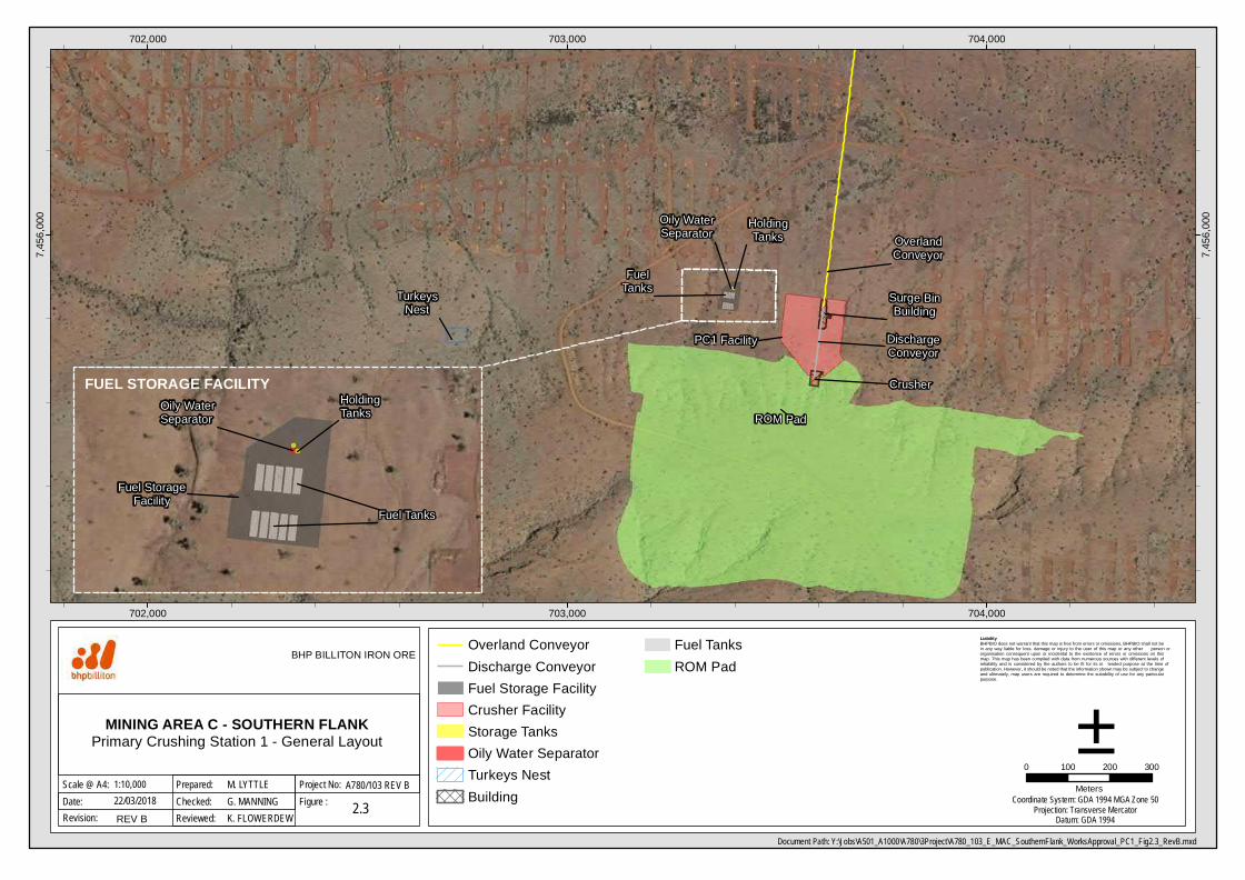
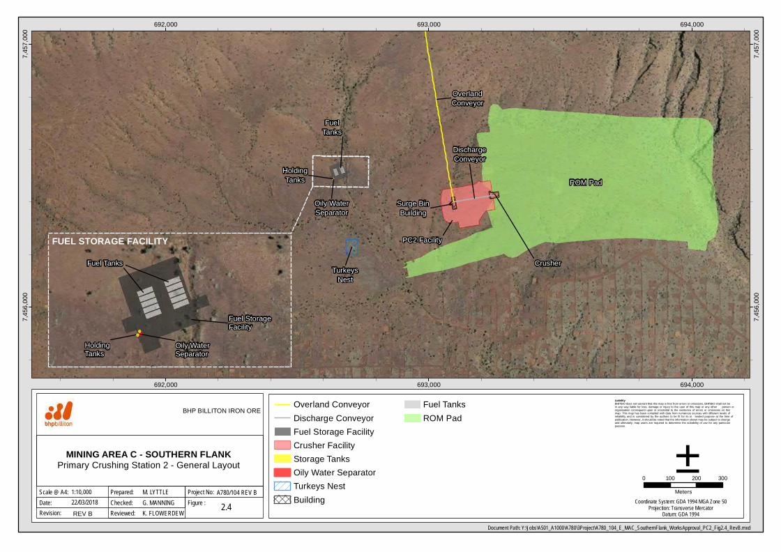
2.1.2.Primary Crushing Stations
Ore from the South Flank via Vista Oriental (PC1) and Grand Central North (PC2) will be processed throughtwo primary crushing (PC) facilities, each with a nameplate capacity of 40Mtpa (Figure 2.1, Figure 2.3 andFigure 2.4 ). The two primary crushing stations (PC1 and PC2) will have a dual truck dump apron located atthe top of a mechanically stabilised earth wall designed to accept ultra-class mining trucks of up to 363tcapacity. Each primary crusher will have a nameplate capacity of 40Mtpa. The mining trucks will feed into theRun of Mine (ROM) bin located over a gyratory crusher that will crush the iron ore to a -250mm top size. Thecrusher will discharge to a surge vault directly beneath. An apron feeder draws ore from the surge vault andloads the discharge conveyor, which feeds onto the overland conveyor (OLC) system (Figure 2.2).
Each the primary crushing facility includes (Attachment 3):
· Rock catchers, truck dump slabs and anchor blocks;
· Primary crushing building including rock breakers;
· Dust suppression (foggers and cannons);
· Primary crushing discharge conveyor; and
· Transfer stations, onto the overland conveyor circuit.
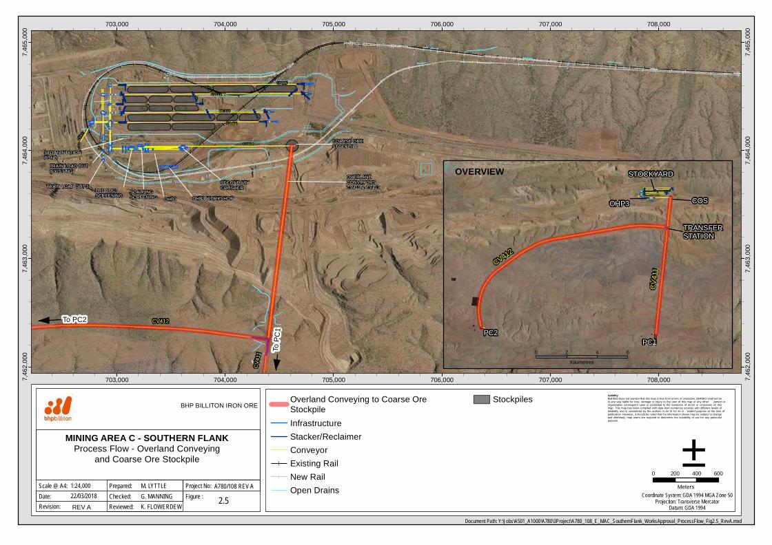
2.1.3.Discharge and Overland Conveyors
Three new overland conveyors will transport primary crushed ore from the primary crushing facilities at SouthFlank to the new coarse ore stockpile (COS) at Mining Area C (Figure 2.5). The discharge conveyors CV402and CV404 will transfer ore from PC1 and PC2 onto the overland conveyors CV411and CV412 via TransferStations TS402 and TS404 (Figure 2.2). The discharge conveyors will each include a magnet, metal detector,Bulk ore conditioning sprays (BOC) sprays, moisture analyser and belt weigher. The overland conveyorsCV411 and CV412 have a design capacity of 7,500 tonnes per hour (tph). The third conveyor CV413 will beloaded with ore by overland conveyor CV412 at Transfer Station TS411. Conveyor CV411 and CV413 willdischarge onto the COS and has a capacity of 15,000tph. All three overland conveyors will be fitted with BOCsprays to ensure the ore is above the DEM moisture content prior to being fed onto the COS.
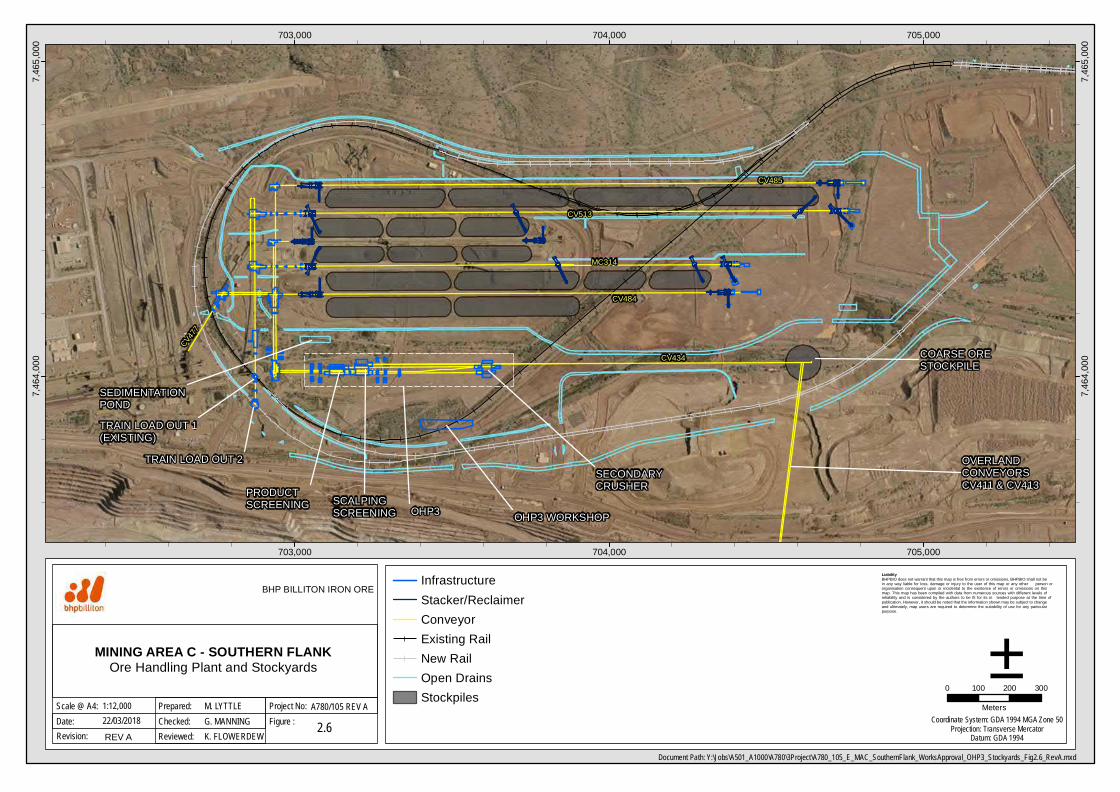
2.1.4.Ore Handling Plant (OHP)
The coarse ore stockpile (COS) will be located inside the rail loop and will receive and store primary crushedore from South Flank (Figure 2.6 and Figure 2.7). It will consist of a conical stockpile above a concrete vaultand tunnel containing two apron feeders for reclaim of the primary crushed ore for loading onto the scalpingscreen feed conveyor for transfer to Ore Handling Plant (OHP) 3. The nameplate production rate for OHP3 is80Mtpa. The key components of the OHP3 comprising of:
· Scalping screening building containing five scalping screening bays (Scheck SLD4385s);
· Secondary crushing building containing four secondary crusher bays (Metso MP1250s)’
· Product screening building containing six product screening bays (Scheck SLD4385s);
· Interconnection conveyors; and
· Lump and fines product conveyors.
The material from the COS feeds the scalping screening building. The scalping screening building arrangementincludes with five screening bays and large screens (Schenck SLD4385DX.). The belt feeders transfer materialfrom the bins onto the double deck screens. Material separates into three streams (Figure 2.2):
· The oversize is conveyed to the Secondary Crushing Building;
· The middlings is directed to the Product Screening Building; and
· The undersize Fines Product is conveyed to the stockyard.
The Secondary Crushing Building includes four Metso MP1250 cone crushers. Ore will be delivered into thesecondary crusher feed bins and transferred to the crusher feed conveyor via a vibrating feeder. The feedconveyor incorporates a metal detector to protect the cone crusher from tramp metal damage. Once crushed,the undersized ore will be discharged onto the product screening feed conveyor. Oversize material will berecirculated through the crushing and screening circuit.
HoldingTanks
Oily WaterSeparator
FuelTanks
PC1 Facility
ROM Pad
Crusher
TurkeysNest
Surge BinBuilding
OverlandConveyor
DischargeConveyor
702,000
702,000
703,000
703,000
704,000
704,000
7,456
,000
7,456
,000
Liability BHPBIO does not warrant that this map is free from errors or omissions. BHPBIO shall not be in any way liable for loss, damage or injury to the user of this map or any other person or organisation consequent upon or incidental to the existence of errors or omissions on this map. This map has been compiled with data from numerous sources with different levels of reliability and is considered by the authors to be fit for its in tended purpose at the time of publication. However, it should be noted that the information shown may be subject to change and ultimately, map users are required to determine the suitability of use for any particular purpose.
Document Path: Y:\Jobs\A501_A1000\A780\3Project\A780_103_E_MAC_SouthernFlank_WorksApproval_PC1_Fig2.3_RevB.mxd
Date:Scale @ A4:
MINING AREA C - SOUTHERN FLANKPrimary Crushing Station 1 - General Layout
0 100 200 300
Meters
2.3
±22/03/2018
BHP BILLITON IRON ORE
Figure :Project No:1:10,000
Checked:Prepared: M. LYTTLE
G. MANNINGA780/103 REV B
Revision: REV B Reviewed: K. FLOWERDEWCoordinate System: GDA 1994 MGA Zone 50
Projection: Transverse MercatorDatum: GDA 1994
Overland ConveyorDischarge ConveyorFuel Storage FacilityCrusher FacilityStorage TanksOily Water SeparatorTurkeys NestBuilding
Fuel TanksROM Pad
Fuel StorageFacility
Fuel Tanks
HoldingTanksOily Water
Separator
FUEL STORAGE FACILITY
TurkeysNest
ROM Pad
PC2 Facility
FuelTanks
Oily WaterSeparator
HoldingTanks
Surge BinBuilding
Crusher
DischargeConveyor
OverlandConveyor
692,000
692,000
693,000
693,000
694,000
694,000
7,456
,000
7,456
,000
7,457
,000
7,457
,000
Liability BHPBIO does not warrant that this map is free from errors or omissions. BHPBIO shall not be in any way liable for loss, damage or injury to the user of this map or any other person or organisation consequent upon or incidental to the existence of errors or omissions on this map. This map has been compiled with data from numerous sources with different levels of reliability and is considered by the authors to be fit for its in tended purpose at the time of publication. However, it should be noted that the information shown may be subject to change and ultimately, map users are required to determine the suitability of use for any particular purpose.
Document Path: Y:\Jobs\A501_A1000\A780\3Project\A780_104_E_MAC_SouthernFlank_WorksApproval_PC2_Fig2.4_RevB.mxd
Date:Scale @ A4:
MINING AREA C - SOUTHERN FLANKPrimary Crushing Station 2 - General Layout
0 100 200 300
Meters
2.4
±22/03/2018
BHP BILLITON IRON ORE
Figure :Project No:1:10,000
Checked:Prepared: M. LYTTLE
G. MANNINGA780/104 REV B
Revision: REV B Reviewed: K. FLOWERDEWCoordinate System: GDA 1994 MGA Zone 50
Projection: Transverse MercatorDatum: GDA 1994
Overland ConveyorDischarge ConveyorFuel Storage FacilityCrusher FacilityStorage TanksOily Water SeparatorTurkeys NestBuilding
Fuel TanksROM Pad
Fuel StorageFacility
Fuel Tanks
HoldingTanks
Oily WaterSeparator
FUEL STORAGE FACILITY
To PC2
To PC
1
CV412
CV41
1
COARSE ORESTOCKPILE
SECONDARYCRUSHERPRODUCT
SCREENING SCALPINGSCREENING
OVERLANDCONVEYORSCV411 & CV413TRAIN LOAD OUT 2
TRAIN LOAD OUT 1(EXISTING)
OHP3 WORKSHOP
SEDIMENTATIONPOND
OHP3
CV434
CV484
CV513
CV485
MC314
CV477
703,000
703,000
704,000
704,000
705,000
705,000
706,000
706,000
707,000
707,000
708,000
708,0007,462
,000
7,462
,000
7,463
,000
7,463
,000
7,464
,000
7,464
,000
7,465
,000
7,465
,000
Liability BHPBIO does not warrant that this map is free from errors or omissions. BHPBIO shall not be in any way liable for loss, damage or injury to the user of this map or any other person or organisation consequent upon or incidental to the existence of errors or omissions on this map. This map has been compiled with data from numerous sources with different levels of reliability and is considered by the authors to be fit for its in tended purpose at the time of publication. However, it should be noted that the information shown may be subject to change and ultimately, map users are required to determine the suitability of use for any particular purpose.
Document Path: Y:\Jobs\A501_A1000\A780\3Project\A780_108_E_MAC_SouthernFlank_WorksApproval_ProcessFlow_Fig2.5_RevA.mxd
Date:Scale @ A4:
0 200 400 600
Meters
2.5
±22/03/2018
BHP BILLITON IRON ORE
Figure :Project No:1:24,000
Checked:Prepared: M. LYTTLE
G. MANNINGA780/108 REV A
Revision: REV A Reviewed: K. FLOWERDEWCoordinate System: GDA 1994 MGA Zone 50
Projection: Transverse MercatorDatum: GDA 1994
Overland Conveying to Coarse OreStockpileInfrastructureStacker/ReclaimerConveyorExisting RailNew RailOpen Drains
Stockpiles
MINING AREA C - SOUTHERN FLANKProcess Flow - Overland Conveying
and Coarse Ore Stockpile
OVERVIEW
CV412
PC2PC1
TRANSFERSTATION
COSOHP3
STOCKYARD
CV41
1
0 2 4 6Kilometres
COARSE ORESTOCKPILE
SECONDARYCRUSHERPRODUCT
SCREENING SCALPINGSCREENING
OVERLANDCONVEYORSCV411 & CV413
TRAIN LOAD OUT 2
TRAIN LOAD OUT 1(EXISTING)
OHP3 WORKSHOP
SEDIMENTATIONPOND
OHP3
CV434
CV484
CV513
CV485
MC314
CV477
703,000
703,000
704,000
704,000
705,000
705,000
7,464
,000
7,464
,000
7,465
,000
7,465
,000
Liability BHPBIO does not warrant that this map is free from errors or omissions. BHPBIO shall not be in any way liable for loss, damage or injury to the user of this map or any other person or organisation consequent upon or incidental to the existence of errors or omissions on this map. This map has been compiled with data from numerous sources with different levels of reliability and is considered by the authors to be fit for its in tended purpose at the time of publication. However, it should be noted that the information shown may be subject to change and ultimately, map users are required to determine the suitability of use for any particular purpose.
Document Path: Y:\Jobs\A501_A1000\A780\3Project\A780_105_E_MAC_SouthernFlank_WorksApproval_OHP3_Stockyards_Fig2.6_RevA.mxd
Date:Scale @ A4:
0 100 200 300
Meters
2.6
±22/03/2018
BHP BILLITON IRON ORE
Figure :Project No:1:12,000
Checked:Prepared: M. LYTTLE
G. MANNINGA780/105 REV A
Revision: REV A Reviewed: K. FLOWERDEWCoordinate System: GDA 1994 MGA Zone 50
Projection: Transverse MercatorDatum: GDA 1994
InfrastructureStacker/ReclaimerConveyorExisting RailNew RailOpen DrainsStockpiles
MINING AREA C - SOUTHERN FLANKOre Handling Plant and Stockyards

To PC2
To PC
1
CV412
CV41
1
COARSE ORESTOCKPILE
SECONDARYCRUSHERPRODUCT
SCREENING SCALPINGSCREENING
OVERLANDCONVEYORSCV411 & CV413TRAIN LOAD OUT 2
TRAIN LOAD OUT 1(EXISTING)
OHP3 WORKSHOP
SEDIMENTATIONPOND
OHP3
CV434
CV484
CV513
CV485
MC314
CV477
703,000
703,000
704,000
704,000
705,000
705,000
706,000
706,000
707,000
707,000
708,000
708,0007,462
,000
7,462
,000
7,463
,000
7,463
,000
7,464
,000
7,464
,000
7,465
,000
7,465
,000
Liability BHPBIO does not warrant that this map is free from errors or omissions. BHPBIO shall not be in any way liable for loss, damage or injury to the user of this map or any other person or organisation consequent upon or incidental to the existence of errors or omissions on this map. This map has been compiled with data from numerous sources with different levels of reliability and is considered by the authors to be fit for its in tended purpose at the time of publication. However, it should be noted that the information shown may be subject to change and ultimately, map users are required to determine the suitability of use for any particular purpose.
Document Path: Y:\Jobs\A501_A1000\A780\3Project\A780_109_E_MAC_SouthernFlank_WorksApproval_ProcessFlow_Fig2.7_RevA.mxd
Date:Scale @ A4:
0 200 400 600
Meters
2.7
±22/03/2018
BHP BILLITON IRON ORE
Figure :Project No:1:24,000
Checked:Prepared: M. LYTTLE
G. MANNINGA780/109 REV A
Revision: REV A Reviewed: K. FLOWERDEWCoordinate System: GDA 1994 MGA Zone 50
Projection: Transverse MercatorDatum: GDA 1994
Coarse Ore Stockpile to OHP3InfrastructureStacker/ReclaimerConveyorExisting RailNew RailOpen DrainsStockpiles
MINING AREA C - SOUTHERN FLANKProcess Flow - Coarse Ore Stockpile and
Ore Handling Plant 3
OVERVIEW
CV412
PC2PC1
TRANSFERSTATION
COSOHP3
STOCKYARD
CV41
1
0 2 4 6Kilometres

Works Approval – Mining Area C South Flank
Page | 18
The secondary crushed ore and the mid-size ore from the scalping screening building will be conveyed into theproduct screening building surge bins. Vibrating feeders will transfer material onto the double deck screenswhich will again separate the ore into three streams. The oversize is recirculated to the Secondary CrushingBuilding for processing. The mid-size reports to the Lump Product Conveyor and undersize to the FinesProduct Conveyor. The lump and fines ore streams are sampled en-route to the stockyard.
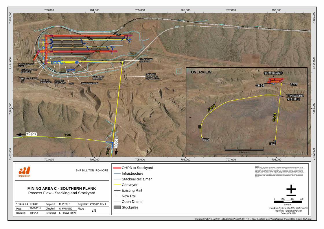
2.1.5.Stacking and Stockyard
Expansion of Stockyard 2 at Mining Area C is required to accommodate the increased production of fines andlump from Mining Area C and South Flank (Figure 2.8). The proposed stockyard facility will have approximately2 million tonnes of live storage capacity in eight stockpiles, with capacity for the same amount of ore to bestacked dead. Two new travelling slewing and luffing stackers with 20,000 tph capacity will be installed.Upgrades to the conveyors and transfers station associated with the existing stacker will be undertaken. Anew travelling, slewing and luffing bucket-wheel reclaimer will be installed to increase reclaiming capacity. Thenew reclaimer has a capacity of with 20,000tph.
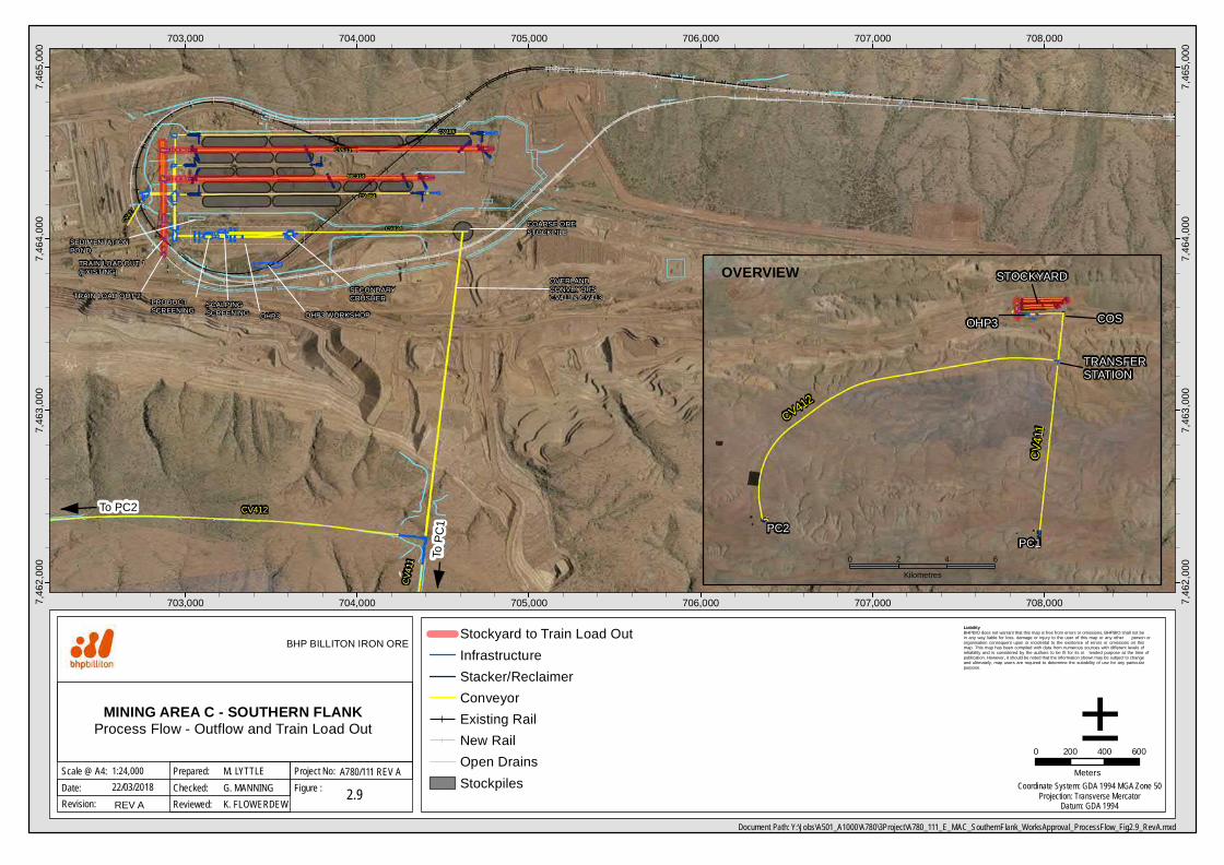
Fines product produced by OHP3 will be blended on belt with existing Mining Area C OHP1 and OHP2 finesproducts prior to stacking in Stockyard 2. Lump product produced by OHP3 will be stacked in Stockyard 2whilst OHP1 and OHP2 lump product will be stacked in Stockyard 1. Lump products will be blended duringtrain loading after staging at Train load out (TLO) 1 via shuttle (Figure 2.9). Products will be reclaimed toeither the existing train load-out facility TLO1 or the new TLO2.
2.1.6.Surface Water and Drainage
The drainage for each primary crushing facility consists of table drains along the perimeters of the processand Non processing infrastructure pads to divert water away from the infrastructure. PC2 also includes aseries of diversion drains to divert water to natural watercourses. A sediment settlement pond will be providedat each primary crushing station to remove sediment laiden discharge from the process areas. Run-off fromthe primary crushing process area will pass through a sedimentation pond, to reduce sediment concentration,before being released back to natural water courses.
The drainage for the COS comprises table drains along the conveyor embankment and culverted crossingsin the drains to discharge water into the existing Mining Area C plant diversion drain.
Drainage for the OHP3 consists of table drains on the north and south sides of the facility, which fall into theplant diversion drain at the northeast end of the OHP3 pad. A settlement pond is proposed on the northwestcorner of the OHP3 pad to remove sediment discharge from process buildings’ wash-down collection sumps.
The drainage works for the Stockyard include new drains and culverts under the existing conveyors at thewestern end to divert water away from the new work areas. Perimeter drains will be constructed around thestockyard to divert water away from the infrastructure. The eastern side of the Stockyard includes a series ofbreaks in the windrows to allow runoff from the stockyard floor to flow into the Mining Area C plant diversiondrain. A settlement pond will be provided at the southeast end of the Stockyard to remove sediment dischargecollected from process areas.
2.1.7.Supporting Works
Additional works are required to support the construction and operation of the processing infrastructure. Theseinclude the:
· A new bin type dual gate TLO2 will be constructed which will tie into a new rail loop outside of theexisting rail loop at Mining Area C.
· The rail loop at Mining Area C will be duplicated and realigned to deliver up to 150 Mtpa of productfrom Mining Area C. Ore will be railed to Port Hedland on BHP’s existing network; and
· Electricity is currently supplied to Mining Area C via a single 33kV overhead transmission line, from the132/33kV Junction Substation, located at the eastern end of ML281SA. Electricity is drawn from theYarnima power station at Newman. Power will be supplied to the South Flank mining area and thenew OHP at Mining Area C via two new 132kV transmission lines from the Junction Substation.
To PC2
To PC
1
CV412
CV41
1
COARSE ORESTOCKPILE
SECONDARYCRUSHERPRODUCT
SCREENING SCALPINGSCREENING
OVERLANDCONVEYORSCV411 & CV413TRAIN LOAD OUT 2
TRAIN LOAD OUT 1(EXISTING)
OHP3 WORKSHOP
SEDIMENTATIONPOND
OHP3
CV434
CV484
CV513
CV485
MC314
CV477
703,000
703,000
704,000
704,000
705,000
705,000
706,000
706,000
707,000
707,000
708,000
708,0007,462
,000
7,462
,000
7,463
,000
7,463
,000
7,464
,000
7,464
,000
7,465
,000
7,465
,000
Liability BHPBIO does not warrant that this map is free from errors or omissions. BHPBIO shall not be in any way liable for loss, damage or injury to the user of this map or any other person or organisation consequent upon or incidental to the existence of errors or omissions on this map. This map has been compiled with data from numerous sources with different levels of reliability and is considered by the authors to be fit for its in tended purpose at the time of publication. However, it should be noted that the information shown may be subject to change and ultimately, map users are required to determine the suitability of use for any particular purpose.
Document Path: Y:\Jobs\A501_A1000\A780\3Project\A780_110_E_MAC_SouthernFlank_WorksApproval_ProcessFlow_Fig2.8_RevA.mxd
Date:Scale @ A4:
0 200 400 600
Meters
2.8
±22/03/2018
BHP BILLITON IRON ORE
Figure :Project No:1:24,000
Checked:Prepared: M. LYTTLE
G. MANNINGA780/110 REV A
Revision: REV A Reviewed: K. FLOWERDEWCoordinate System: GDA 1994 MGA Zone 50
Projection: Transverse MercatorDatum: GDA 1994
OHP3 to StockyardInfrastructureStacker/ReclaimerConveyorExisting RailNew RailOpen DrainsStockpiles
MINING AREA C - SOUTHERN FLANKProcess Flow - Stacking and Stockyard
OVERVIEW
CV412
PC2PC1
TRANSFERSTATION
COSOHP3
STOCKYARD
CV41
1
0 2 4 6Kilometres
To PC2
To PC
1
CV412
CV41
1
COARSE ORESTOCKPILE
SECONDARYCRUSHERPRODUCT
SCREENING SCALPINGSCREENING
OVERLANDCONVEYORSCV411 & CV413TRAIN LOAD OUT 2
TRAIN LOAD OUT 1(EXISTING)
OHP3 WORKSHOP
SEDIMENTATIONPOND
OHP3
CV434
CV484
CV513
CV485
MC314
CV477
703,000
703,000
704,000
704,000
705,000
705,000
706,000
706,000
707,000
707,000
708,000
708,0007,462
,000
7,462
,000
7,463
,000
7,463
,000
7,464
,000
7,464
,000
7,465
,000
7,465
,000
Liability BHPBIO does not warrant that this map is free from errors or omissions. BHPBIO shall not be in any way liable for loss, damage or injury to the user of this map or any other person or organisation consequent upon or incidental to the existence of errors or omissions on this map. This map has been compiled with data from numerous sources with different levels of reliability and is considered by the authors to be fit for its in tended purpose at the time of publication. However, it should be noted that the information shown may be subject to change and ultimately, map users are required to determine the suitability of use for any particular purpose.
Document Path: Y:\Jobs\A501_A1000\A780\3Project\A780_111_E_MAC_SouthernFlank_WorksApproval_ProcessFlow_Fig2.9_RevA.mxd
Date:Scale @ A4:
0 200 400 600
Meters
2.9
±22/03/2018
BHP BILLITON IRON ORE
Figure :Project No:1:24,000
Checked:Prepared: M. LYTTLE
G. MANNINGA780/111 REV A
Revision: REV A Reviewed: K. FLOWERDEWCoordinate System: GDA 1994 MGA Zone 50
Projection: Transverse MercatorDatum: GDA 1994
Stockyard to Train Load OutInfrastructureStacker/ReclaimerConveyorExisting RailNew RailOpen DrainsStockpiles
MINING AREA C - SOUTHERN FLANKProcess Flow - Outflow and Train Load Out
OVERVIEW
CV412
PC2PC1
TRANSFERSTATION
COSOHP3
STOCKYARD
CV41
1
0 2 4 6Kilometres
Works Approval – Mining Area C South Flank
Page | 21
2.2. Category 73 – Bulk Fuel Storage
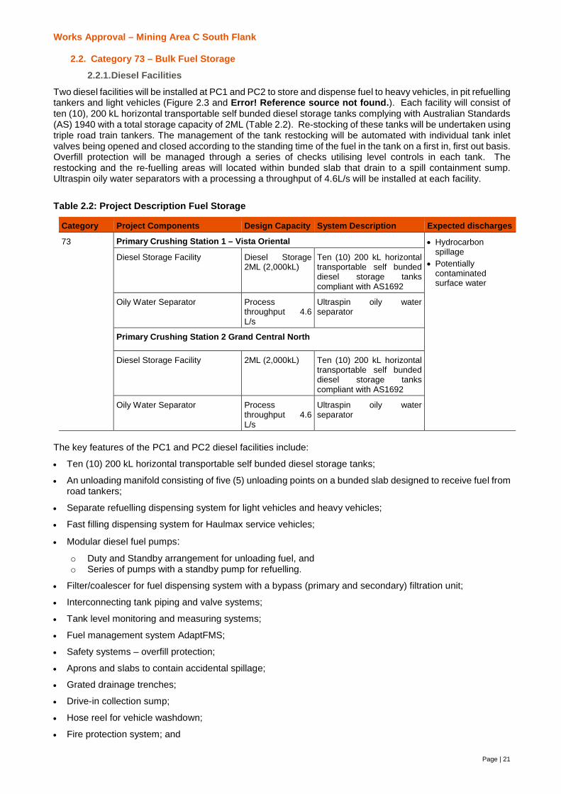
2.2.1.Diesel Facilities
Two diesel facilities will be installed at PC1 and PC2 to store and dispense fuel to heavy vehicles, in pit refuellingtankers and light vehicles (Figure 2.3 and Error! Reference source not found.). Each facility will consist often (10), 200 kL horizontal transportable self bunded diesel storage tanks complying with Australian Standards(AS) 1940 with a total storage capacity of 2ML (Table 2.2). Re-stocking of these tanks will be undertaken usingtriple road train tankers. The management of the tank restocking will be automated with individual tank inletvalves being opened and closed according to the standing time of the fuel in the tank on a first in, first out basis.Overfill protection will be managed through a series of checks utilising level controls in each tank. Therestocking and the re-fuelling areas will located within bunded slab that drain to a spill containment sump.Ultraspin oily water separators with a processing a throughput of 4.6L/s will be installed at each facility.
Table 2.2: Project Description Fuel Storage
Category Project Components Design Capacity System Description Expected discharges
73 Primary Crushing Station 1 – Vista Oriental · Hydrocarbonspillage
· Potentiallycontaminatedsurface water
Diesel Storage Facility Diesel Storage2ML (2,000kL)
Ten (10) 200 kL horizontaltransportable self bundeddiesel storage tankscompliant with AS1692
Oily Water Separator Processthroughput 4.6L/s
Ultraspin oily waterseparator
Primary Crushing Station 2 Grand Central North
Diesel Storage Facility 2ML (2,000kL) Ten (10) 200 kL horizontaltransportable self bundeddiesel storage tankscompliant with AS1692
Oily Water Separator Processthroughput 4.6L/s
Ultraspin oily waterseparator
The key features of the PC1 and PC2 diesel facilities include:
· Ten (10) 200 kL horizontal transportable self bunded diesel storage tanks;
· An unloading manifold consisting of five (5) unloading points on a bunded slab designed to receive fuel fromroad tankers;
· Separate refuelling dispensing system for light vehicles and heavy vehicles;
· Fast filling dispensing system for Haulmax service vehicles;
· Modular diesel fuel pumps:o Duty and Standby arrangement for unloading fuel, ando Series of pumps with a standby pump for refuelling.
· Filter/coalescer for fuel dispensing system with a bypass (primary and secondary) filtration unit;
· Interconnecting tank piping and valve systems;
· Tank level monitoring and measuring systems;
· Fuel management system AdaptFMS;
· Safety systems – overfill protection;
· Aprons and slabs to contain accidental spillage;
· Grated drainage trenches;
· Drive-in collection sump;
· Hose reel for vehicle washdown;
· Fire protection system; and

Works Approval – Mining Area C South Flank
22
· Oily water separator.
Attachment 3 and Table 2.3 outline the design and controls of the facility.
Table 2.3: Key Features of Diesel Storage Facility at PC1 and PC2
Aspect Description
Storage Facility
Number of Tanks 10
Double Walled, Category 4, horizontal storage tank to comply with the requirementsof AS1692.
Tank Safe Fill Level 200kL
Nominal Total Storage Capacity <2,000kL
Material of Construction Carbon steel, AS3678 Grade 250 with tensile strength410MPaInternal surfaces will be coated against corrosion
Tank Nozzels Inlets fitted with mechanical overfill protection and the outlets with anti-siphon valve
Valves Double block and bleed isolation valves at each tank inlet and outlet.The valve furthest from the tank is to be fail-closed pneumatically actuated withopen/closed position feedback to the PLC.
Instrumentation Each tank has:
· Level transmitter with low and high alarm set points; and
· Independent high-high level switch.
Overfill Protection The high level alarm and independent high-high level switch are to be set inaccordance with API RP 2350.The tank inlet shall be fitted with mechanical overfill protectionThe double walled tanks shall include an interstitial leakage monitoring probesystem
Unloading System
Capacity of delivery fuel Maximum tanker size 135kL
Unloading Points One point with five unloading connections. Each connection will have a dedicatedisolation valve.A separate docking rack to hook the couplings up to when not in use.The unloading pad will be a single concrete slab requiring triple road tanker trainsto be moved progressively onto the slab for the unloading of diesel fuel and the padshall be sized to the tankers unloading manifold
Unloading Pumps Two pumps in a duty and stand-by arrangement.The pump skids are to be fully bunded with the capacity to contain a 20 year rainevent for 72 hours. Each skid is to be provided with a manual isolation valve to allowdrainage of the skid to either the local sump or to a collection truck.
Valves Isolation valves at each pump and non-return valves fitted on the downstream line.Isolation valves at each off-loading connection.
Flow Metering A positive displacement meter suitable for 750 – 2200 L/min complete with strainerand air eliminator.
Flow Control To be set for slow start and slow completion of delivery to minimise system hydraulicshock and allow for slow filter filling.
Drainage A bunded spill pad will surround the unloading area. The pad tied into the LVrefuelling pad and fall to a collection sump. The flow from the sump shall fall to themain area collection sump
Spillage Spill kit compliant to AS1940 requirements will be available at all unloading points.Concrete spillage slabs or bunded steel skids capture leaks and spills fromoperations and maintenance activities around pumps, drains and tank headers. Theslabs graded to a drainage channel with a minimum fall of 1:100 before to acollection sump.The spillage channels are constructed from concrete and are covered with opengrating to permit an inspection and wash down of these trenches as required
Refuelling System

Works Approval – Mining Area C South Flank
23
Aspect Description
HV Refuelling LV Refuelling
Refuelling Points Will have designated areas for therefuelling of Light Vehicles, heavyvehicles and Haul maxThe heavy vehicle refuelling slab shall besized to suit a 290 tonne haul truck and aHaulmax service truckLockout system to prevent truck drivingaway without decoupling the refuellingnozzle.
The light vehicle-refuelling slab shallaccommodate a standard sitespecification utility vehicle and lightvehicle trucks.
Fuel connections The haul truck and HaulMax refuellingnozzles to a spring balanced loading armand fitted with breakaway couplings.Each refuelling nozzle with a dockingstand with return position switch and to belinked to the PLC.
Refuelling Pumps Series of pumps with a standby pump.The pump skids are to be fully bundedwith the capacity to contain a 20 year rainevent for 72 hours. Each skid is to beprovided with a manual isolation valve toallow drainage of the skid to either thelocal sump or to a collection truck.
A single stand-alone duty pump tosupply diesel to the bowser.
Pipework NA Carbon Steel/dual contained pipe.The LV system requires a section of pipeto be run underground beneath thetanker offloading bay. The designcontractor is to propose a dual containedsystem with leak detection connected
Bowser NA Single bowser to come with a filter,positive displacement flow meter, andunder sump.
Valves Isolation valves at each pump and filterwith non-return valves fitted on thedownstream line of each filter.Isolation valves at each refuellingconnection.
A manual isolation valve prior to thepump. An actuated valve shall beprovided downstream of the pump.The bowser shall incorporate a shearvalve
Flow Metering A positive displacement meter suitable for750 – 2200 L/min complete with strainerand air eliminator.The meter is to have a local displayindicating flow rate and batch volume andsupply a pulse output to the fuelmanagement system.
Drainage A bunded spill pad at the HV refuellingslab. The slab shall drain to a containmentsump capable of containing a 9,000L spill
The refuelling bunded slab shall beintegrated with the tanker unloadingslab. The slab shall drain to a sumpcapable of containing a 300L spill.
Spillage Spill kit compliant to AS1940 requirements provided at all refuelling points.Concrete spillage slabs or bunded steel skids capture leaks and spills fromoperations and maintenance activities around pumps, drains and tank headers. Theslabs graded to a drainage channel with a minimum fall of 1:100 before to acollection sump.The spillage channels are constructed from concrete and are covered with opengrating to permit an inspection and wash down of these trenches as required
2.2.2.Oily Water Separator
An Ultraspin oily water separator unit will be located at PC1, PC2 and the MEM Precinct to treat surface waterrunoff potentially contaminated by hydrocarbons. Each Ultraspin will have a processing throughput capacity4.6L/s.

Works Approval – Mining Area C South Flank
24
Potentially contaminated surface water from each bunded area will be channelled into a collection sump beforepassing through an oily water separator. The oily water collection sumps at PC1 and PC2 are designed tocontain the first flush volume (initial 20 minutes of rainfall) from the bunded fuel loading and unloading tanksand tank nozzle bunds plus the largest potential diesel release from one of vehicles (9,000 litres). After the first20 minutes of rainfall any further surface water runs off the bunded slabs to the local stormwater drainagesystem. The sump is fitted with low and high level switches.
The oily water separator will treat the water to a total recoverable hydrocarbon (TRH) concentration of 15mg/Lor less. The system will be fitted with a local high oil alarm and a signal back to the site PLC of the dieselstorage facility. Treated water from the oily water separator will be transferred to a local 5 kL holding tank formonitoring. Holding tanks will retain the treated water until there is a manual intervention to confirm that theTRH concentration has been met and the water may be released to the turkey’s nests. The oily water separatorwill shut down once the holding tank is full. The holding tank shall be fitted with a sample point for manualsampling and fitted with a hydrocarbon sensor. Water from the turkey’s nest will be utilised for dustsuppression. The turkey’s nest will be lined with 1.5mm HDPE liner. A spillway will direct water overflow waterto the adjacent diversion drain (Attachment 3). Waste oil will be captured in a 5 kL tank for removal and disposaloff site at an appropriate disposal facility.
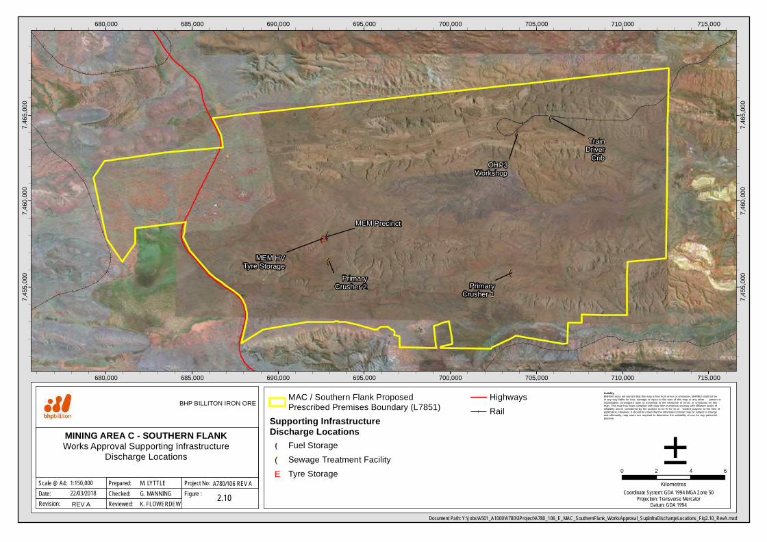
2.3. Supporting Facilities
To support the mining operations and workforce the following infrastructure is required:
· Mining Area C area new buildings and facilities:
o Sample preparation building expansion;
o OHP3 and Conveyor Maintenance Workshops with office, crib and ablution facilities;
o Shutdown Execution Centre; and
o Train Driver crib and ablutions facilities.
· South Flank area buildings and facilities:
o Unmanned mine access gate;
o Mobile equipment maintenance (MEM) Precinct. The Precinct will include; a warehousedelivery and laydown area, tyre storage and exchange facility, waste water tanks, maintenanceworkshop, wash-down facility and parking.
o South Flank ammonium nitrate (AN) products facility;
o Office, crib and ablution facilities at PC1 and PC2.
· Seal and unsealed access roads;
· Expansion of Mulla Mulla village to final capacity of 3,000 rooms. Expansion of Mulla Mulla waste watertreatment plant (approved by works approval W6092/2017/1);
· Expansion of water infrastructure for provision of services to new plant and NPI;
· New powerlines and substations to provide power.
The capacities of the above facilities do not trigger the design capacities of the Environmental ProtectionRegulations 1987 or contribute to the emissions of an existing licenced facility (Figure 2.10).
2.3.1.Category 57 – Used Tyre Storage
Used tyres generated from the maintenance of heavy and light vehicles will be stored at the MEM precinct. Upto 70 used tyres will be stored at any one time with a minimum separation distance of 6m between the stacksin accordance with conditions of Licence L7851/2002/6 (Table 2.4). The used tyres will be trucked to the MiningArea C inert landfill or an overburden storage area (OSA) for disposal. Landfilling of the used tyres will beundertaken in accordance with the Environmental Protection Regulations 1987 and Environmental Protection(Controlled Wastes) Regulations 2004 and the conditions of Licence L7851/2002/6 (Attachment 4).
Table 2.4: L7851/2002/6 Table 1.2.2.: Waste Processing
Waste Types Process Process Limit
Inert Waste Type 2 - Tyres Receipt, Handling, storage prior to disposalby landfilling
To be stored in piles up to 100 units with a6m separation distance between piles
Tyres/rubber shall only be landfilled in
Works Approval – Mining Area C South Flank
25
Waste Types Process Process Limit
overburden storage areas located within theprescribed premises boundary shown inSchedule 1
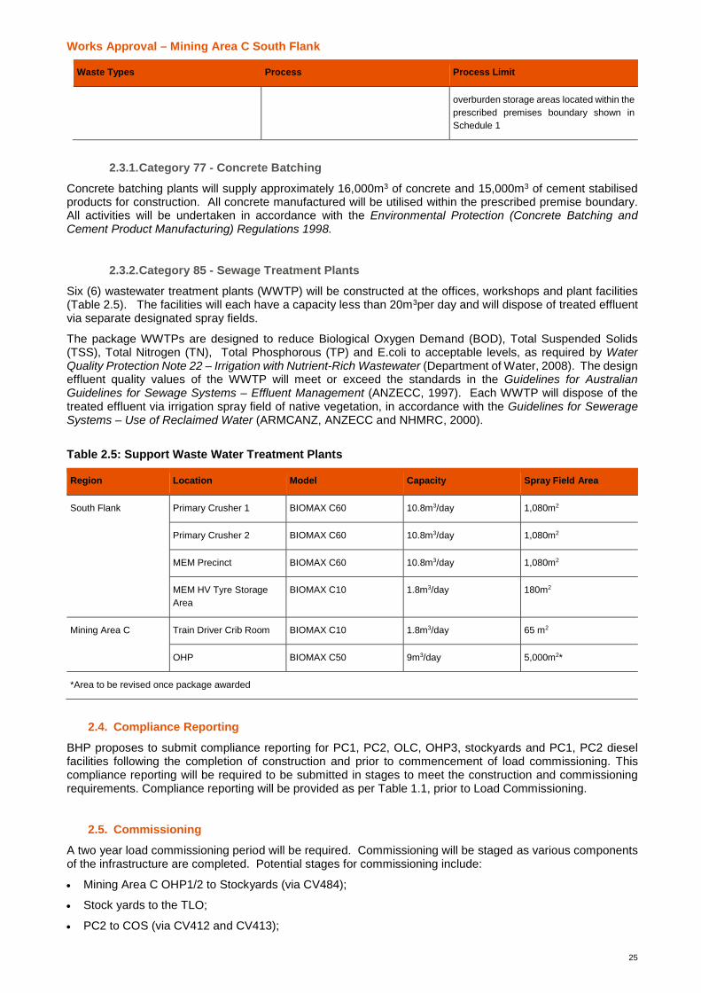
2.3.1.Category 77 - Concrete Batching
Concrete batching plants will supply approximately 16,000m3 of concrete and 15,000m3 of cement stabilisedproducts for construction. All concrete manufactured will be utilised within the prescribed premise boundary.All activities will be undertaken in accordance with the Environmental Protection (Concrete Batching andCement Product Manufacturing) Regulations 1998.
2.3.2.Category 85 - Sewage Treatment Plants
Six (6) wastewater treatment plants (WWTP) will be constructed at the offices, workshops and plant facilities(Table 2.5). The facilities will each have a capacity less than 20m3per day and will dispose of treated effluentvia separate designated spray fields.
The package WWTPs are designed to reduce Biological Oxygen Demand (BOD), Total Suspended Solids(TSS), Total Nitrogen (TN), Total Phosphorous (TP) and E.coli to acceptable levels, as required by WaterQuality Protection Note 22 – Irrigation with Nutrient-Rich Wastewater (Department of Water, 2008). The designeffluent quality values of the WWTP will meet or exceed the standards in the Guidelines for AustralianGuidelines for Sewage Systems – Effluent Management (ANZECC, 1997). Each WWTP will dispose of thetreated effluent via irrigation spray field of native vegetation, in accordance with the Guidelines for SewerageSystems – Use of Reclaimed Water (ARMCANZ, ANZECC and NHMRC, 2000).
Table 2.5: Support Waste Water Treatment Plants
Region Location Model Capacity Spray Field Area
South Flank Primary Crusher 1 BIOMAX C60 10.8m3/day 1,080m2
Primary Crusher 2 BIOMAX C60 10.8m3/day 1,080m2
MEM Precinct BIOMAX C60 10.8m3/day 1,080m2
MEM HV Tyre StorageArea
BIOMAX C10 1.8m3/day 180m2
Mining Area C Train Driver Crib Room BIOMAX C10 1.8m3/day 65 m2
OHP BIOMAX C50 9m3/day 5,000m2*
*Area to be revised once package awarded
2.4. Compliance Reporting
BHP proposes to submit compliance reporting for PC1, PC2, OLC, OHP3, stockyards and PC1, PC2 dieselfacilities following the completion of construction and prior to commencement of load commissioning. Thiscompliance reporting will be required to be submitted in stages to meet the construction and commissioningrequirements. Compliance reporting will be provided as per Table 1.1, prior to Load Commissioning.
2.5. Commissioning
A two year load commissioning period will be required. Commissioning will be staged as various componentsof the infrastructure are completed. Potential stages for commissioning include:
· Mining Area C OHP1/2 to Stockyards (via CV484);
· Stock yards to the TLO;
· PC2 to COS (via CV412 and CV413);

Works Approval – Mining Area C South Flank
26
· COS to Stockyards (via CV476)
· PC1 to COS (via CV411;
· North Stock yard to TLO;
· COS to OHP3 to stockyards (via CV473); and
· OHP1/2 to stockyards (via CV478).
Performance testing and reliability testing will be undertaken during the commissioning phase. Commissioningshall verify that the facilities are capable of continuously operating to design criteria and specifications. Thisverification will include performance testing of the dust emission controls. Dust emission will be monitored viathe existing air quality monitoring network. Maintenance strategies to ensure performance longevity for thesekey design elements are developed pre-commissioning and are implemented at the completion of thecommissioning process.
All commissioning activities for Mining Area C - South Flank Project shall comply with the South Flank HSECManagement Plan and the conditions of the works approval. A commissioning management plan is inpreparation and will be submitted to the DWER.
!
!
!!
!
!
(
(
((
(
(
E!(
OHP3Workshop
TrainDriver
Crib
MEM Precinct
MEM HVTyre Storage
PrimaryCrusher 2 Primary
Crusher 1
680,000
680,000
685,000
685,000
690,000
690,000
695,000
695,000
700,000
700,000
705,000
705,000
710,000
710,000
715,000
715,000
7,455
,000
7,455
,000
7,460
,000
7,460
,000
7,465
,000
7,465
,000
Liability BHPBIO does not warrant that this map is free from errors or omissions. BHPBIO shall not be in any way liable for loss, damage or injury to the user of this map or any other person or organisation consequent upon or incidental to the existence of errors or omissions on this map. This map has been compiled with data from numerous sources with different levels of reliability and is considered by the authors to be fit for its in tended purpose at the time of publication. However, it should be noted that the information shown may be subject to change and ultimately, map users are required to determine the suitability of use for any particular purpose.
Document Path: Y:\Jobs\A501_A1000\A780\3Project\A780_106_E_MAC_SouthernFlank_WorksApproval_SupInfraDischargeLocations_Fig2.10_RevA.mxd
Date:Scale @ A4:
MINING AREA C - SOUTHERN FLANKWorks Approval Supporting Infrastructure
Discharge Locations0 2 4 6
Kilometres
2.10
±22/03/2018
BHP BILLITON IRON ORE
Figure :Project No:1:150,000
Checked:Prepared: M. LYTTLE
G. MANNINGA780/106 REV A
Revision: REV A Reviewed: K. FLOWERDEWCoordinate System: GDA 1994 MGA Zone 50
Projection: Transverse MercatorDatum: GDA 1994
MAC / Southern Flank ProposedPrescribed Premises Boundary (L7851)
Supporting InfrastructureDischarge Locations!( Fuel Storage!( Sewage Treatment FacilityE Tyre Storage
HighwaysRail
Works Approval – Mining Area C South Flank
Page | 28
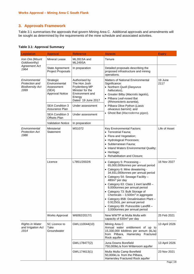
3. Approvals FrameworkTable 3.1 summarises the approvals that govern Mining Area C. Additional approvals and amendments willbe sought as determined by the requirements of the mine schedule and associated activities.
Table 3.1: Approval Summary
Legislation Approval Reference Aspects Expiry
Iron Ore (MountGoldsworthy)Agreement Act1964
Mineral Lease ML281SA andML249SA
Tenure
State AgreementProject Proposals
In preparation Detailed proposals describing theproposed infrastructure and miningoperations.
EnvironmentalProtection andBiodiversity Act1999
StrategicEnvironmentalAssessment(SEA)Approval Notice
Authorised byThe Hon JoshFrydenberg MPMinister for theEnvironment andEnergyDated 19 June 2017
Matters of National EnvironmentalSignificance:· Northern Quoll (Dasyurus
hallucatus),· Greater Bilby (Macrotis lagotis),· Pilbara Leaf-nosed Bat
(Rhinonicteris aurantia),· Pilbara Olive Python (Liasis
olivaceus barroni); and· Ghost Bat (Macroderma gigas).
19 June2117
SEA Condition 3Assurance Plan
Under assessment
SEA Condition 3Offsets Plan
Under assessment
Validation Notice In preparation
EnvironmentalProtection Act1986
MinisterialStatement
MS1072 Key Environmental Factors:· Terrestrial Fauna;· Flora and Vegetation;· Hydrological Processes;· Subterranean Fauna;· Inland Waters Environmental Quality;· Heritage;· Rehabilitation and Closure;
Life of Asset
Licence L7851/2002/6 · Category 5: Processing –65,000,000tonnes per annual period
· Category 6: Mine dewatering -34,931,000tonnes per annual period
· Category 54: Sewage Facility –480m3 per day
· Category 63: Class 1 inert landfill –9,000tonnes per annual period
· Category 73: Bulk Storage ofChemicals – 3,500m3 in aggregate
· Category 85B: Desalinisation Plant –0.9125GL per annual period
· Category 89: Putrescible Landfill –3,000tonnes per annual period
16 Nov 2027
Works Approval W6092/2017/1 New WWTP at Mulla Mulla withcapacity of 630m3 per day
25 Feb 2021
Rights in Waterand Irrigation Act1914
5C Licence toTakeGroundwater
GWL110044(10) Mining Area CAnnual water entitlement of up to15,330,000 kilolitres per annum (kL/a)from Pilbara, Hamersley FracturedRock aquifer.
13 April 2026
GWL178477(2) Juna Downs Borefield750,000kL/a from Wittenoom aquifer
13 April 2026
GWL174613(1) Mulla Mulla Camp Borefield50,000kL/a from the Pilbara,Hamersley Fractured Rock aquifer
23 Nov 2021

Works Approval – Mining Area C South Flank
29
Legislation Approval Reference Aspects Expiry
AboriginalHeritage Act 1972
Section 18Notices
Approved 16 March2018
Salvage and disturbance of heritagesites
Under assessment Salvage and disturbance of heritagesites
Dangerous Goodsand Safety Act2004
DangerousGoods andStorage Licence
DGS017237 Facilities added to the manifest asrequired.
Health Act 1914 Permit to installapparatus for thetreatment ofsewage
In preparation. Will besubmitted asdetermined byschedule and siterequirements
To Construct a waste water treatmentplant
Permit to installapparatus for thetreatment ofsewage – MullaMulla VillageWWTP
Under assessmentsubmitted 12 Feb 2018
Permit to operateapparatus for thetreatment ofsewage
Submission followingconstruction of thesewage treatmentfacility, as required.
To operate a waste water treatmentplant
3.1. State Agreement
Mining Area C is located on land that is held pursuant to the Iron Ore (Mount Goldsworthy) Agreement Act1964. The Mine has been the subject of multiple approved proposals under this Agreement since 2002. Twodetailed proposals will be submitted for South Flank. The first application will outline early works to enableaccess to the site and the second will describe the full mine development.
3.2. Environmental Protection and Biodiversity Conservation Act 1999 (EPBC Act)
On 19 June 2017 the Minister for the Environment and Energy (Cwth) approved actions associated withdeveloping future iron ore mines and associated infrastructure in the Pilbara region of Western Australia asdescribed in a strategic assessment program issued in accordance with Section 146(1) of the EnvironmentProtection and Biodiversity Conservation Act 1999. The implementation framework of the Program comprisestwo plans: an Assurance Plan and an Offsets Plan. The Assurance Plan and the Offsets Plan under assessmentby the Department of Environment and Energy (DoEE).
South Flank will be subject to a Validation process under the Program following endorsement of the Assuranceand Offsets Plan. The Validation Notice will describe how the potential impact to the Matters of NationalSignificant (NES) species will be managed to ensure the Program Matter Outcomes are achieved. BHP willpublish a draft Validation Notice for public comment for at least 28 days, with any comments received to betaken into account when finalising the Validation Notice.
3.3. Part IV of the EP Act
In 1998, BHP received approval under Part IV of the Environmental Protection Act 1986 (EP Act) for the multipleIron Ore Mine Development Area Mining Area C Northern Flank via Ministerial Statement 491 (MS491).
On 30 May 2016, BHPBIO referred the proposal to develop and operate a satellite orebody at South Flank aspart of its Mining Area C operations, under Part IV of the EP Act. The referral also sought to expand the scopeof disturbance currently approved at the Mining Area C hub and create a single Ministerial Statement to governthe Northern and South Flanks. The EPA assessed the proposal at the Public Environmental Review (PER)level.
A Ministerial Statement of Approval No.1072 (MS1072) was issued by the Minister for Environment on 20February 2018 under Part IV of the EP Act. All works will be undertaken in accordance with the conditions ofthe MS1072, which supersedes MS491. MS1072 permits the clearing of native vegetation up to 21,824ha(inclusive of 5,564ha cleared in accordance with MS491).

Works Approval – Mining Area C South Flank
30
3.4. Part V of the EP Act
BHP Billiton currently holds a Licence to Operate (L7851/2002/6) for the approved Mining Area C operations.The prescribe premises categories permitted under the licence include 5, 6, 54, 63, 73, 85B and 89 (Table 3.1).Table 3.2 outlines the Part V approvals framework to allow construction of Mining Area C and South Flankinfrastructure.
Table 3.2: Mining Area C and South Flank Part V Submissions
Mining Area C L7851 Licence Amendmentsubmitted Jan 2018
Works Approval Application (this application)
Category Existing LicenceCapacity
Proposed capacity Project Components ProposedCapacity
5 - ProcessInfrastructure
65,000,000 tonnesper annual period
Increase capacity to71,000,000* tonnesper annual period
South Flank - Two 40Mtpaprimary crushing stations,discharge and overlandconveyors transfer stations
Mining Area C - Coarse orestockpile, OHP 3 (150Mtpa),ore sampling stations,stockyard expansion
Increase capacity to150,000,000*tonnes per annualperiod
6 – Dewatering 34,931,000 tonnesper annual period
Addition of injectionbores and newdischarge points
No change No change
12 – Screening - Add the category up to1,000,000 tonnes perannual period
No change No change
54 – SewageFacility
480 m3 per day No change No change No change
63 – Class I InertLandfill
9,000 tonnes perannual period
Increase to 14,000tonnes per annualperiod to account foran increase in inertwaste resulting fromthe construction of theSouth Flank mininghub.
No change No change
73 – Bulk Storageof Chemicals
3,500m3 inaggregate
Increase to 6,000 m3
to allow for theinstallation ofadditional 15 fuelbullets at MAC andSouth Flank (inclusiveof the fuel storage atMEM precinct), and toallow flexibility in futurehydrocarbon storagewithin the revisedboundary ofL7851/2002/6.
Installation of the two 2,000kLfuel storage facilities at PC1and PC2,
Increase to10,000m3
85B - WaterDesalination Plant
0.9125 gigalitres perannual period
No change No change No change
89 - PutrescibleLandfill Site
3,000 tonnes perannual period
Increase to 5,000tonnes per annualperiod to account foran increase inputrescible waste
No change No change
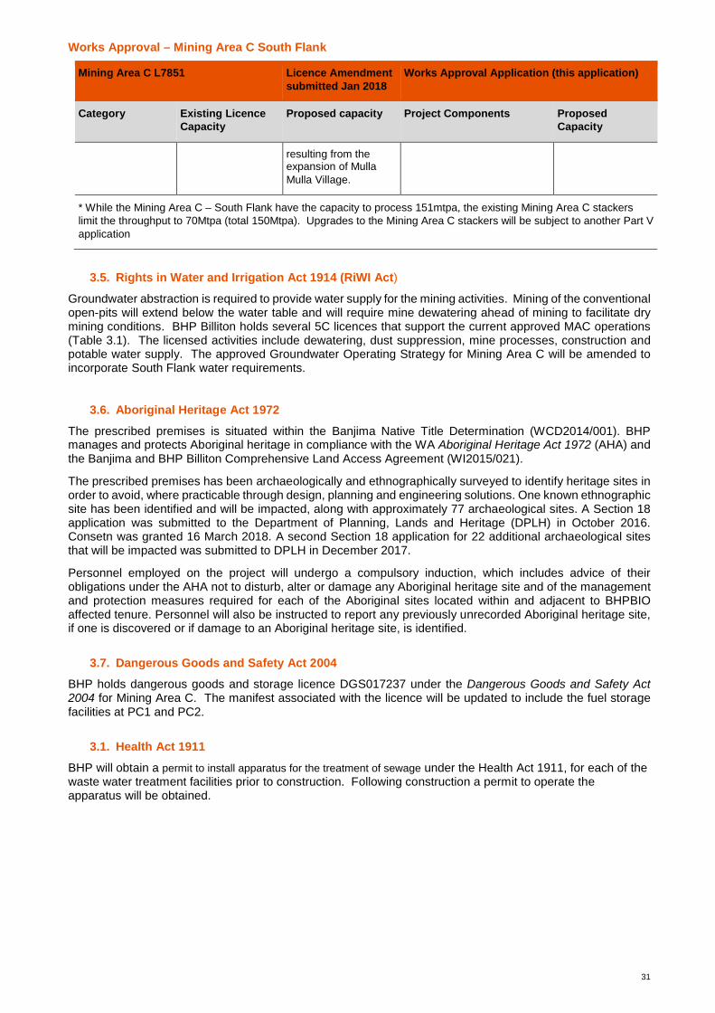
Works Approval – Mining Area C South Flank
31
Mining Area C L7851 Licence Amendmentsubmitted Jan 2018
Works Approval Application (this application)
Category Existing LicenceCapacity
Proposed capacity Project Components ProposedCapacity
resulting from theexpansion of MullaMulla Village.
* While the Mining Area C – South Flank have the capacity to process 151mtpa, the existing Mining Area C stackerslimit the throughput to 70Mtpa (total 150Mtpa). Upgrades to the Mining Area C stackers will be subject to another Part Vapplication
3.5. Rights in Water and Irrigation Act 1914 (RiWI Act)
Groundwater abstraction is required to provide water supply for the mining activities. Mining of the conventionalopen-pits will extend below the water table and will require mine dewatering ahead of mining to facilitate drymining conditions. BHP Billiton holds several 5C licences that support the current approved MAC operations(Table 3.1). The licensed activities include dewatering, dust suppression, mine processes, construction andpotable water supply. The approved Groundwater Operating Strategy for Mining Area C will be amended toincorporate South Flank water requirements.
3.6. Aboriginal Heritage Act 1972
The prescribed premises is situated within the Banjima Native Title Determination (WCD2014/001). BHPmanages and protects Aboriginal heritage in compliance with the WA Aboriginal Heritage Act 1972 (AHA) andthe Banjima and BHP Billiton Comprehensive Land Access Agreement (WI2015/021).
The prescribed premises has been archaeologically and ethnographically surveyed to identify heritage sites inorder to avoid, where practicable through design, planning and engineering solutions. One known ethnographicsite has been identified and will be impacted, along with approximately 77 archaeological sites. A Section 18application was submitted to the Department of Planning, Lands and Heritage (DPLH) in October 2016.Consetn was granted 16 March 2018. A second Section 18 application for 22 additional archaeological sitesthat will be impacted was submitted to DPLH in December 2017.
Personnel employed on the project will undergo a compulsory induction, which includes advice of theirobligations under the AHA not to disturb, alter or damage any Aboriginal heritage site and of the managementand protection measures required for each of the Aboriginal sites located within and adjacent to BHPBIOaffected tenure. Personnel will also be instructed to report any previously unrecorded Aboriginal heritage site,if one is discovered or if damage to an Aboriginal heritage site, is identified.
3.7. Dangerous Goods and Safety Act 2004
BHP holds dangerous goods and storage licence DGS017237 under the Dangerous Goods and Safety Act2004 for Mining Area C. The manifest associated with the licence will be updated to include the fuel storagefacilities at PC1 and PC2.
3.1. Health Act 1911
BHP will obtain a permit to install apparatus for the treatment of sewage under the Health Act 1911, for each of thewaste water treatment facilities prior to construction. Following construction a permit to operate theapparatus will be obtained.

Works Approval – Mining Area C South Flank
Page | 32
4. Stakeholder ConsultationBHP Billiton’s commitment to community engagement are articulated in the Company’s Code of BusinessConduct (BHP Billiton, 2016a), which states:
Our ability to build relationships and work collaboratively and transparently with our host communitiesis critical to our long term success. BHP Billiton aims to be valued and respected by the communitiesin which we operate.
To support this commitment, BHP Billiton has comprehensive Company standards and dedicated resources toensure its activities are underpinned by continuous community engagement and feedback.
BHP Billiton undertakes regular and ongoing stakeholder engagement as part of its core business activities.BHP Billiton’s Our Requirements1 Community sets out the Company’s approved mandatory and minimumperformance requirements for community engagement (BHP Billiton, 2016b). BHP Billiton aims to facilitateregular, open and honest dialogue to understand expectations, concerns and interests of stakeholders and toincorporate them into business planning to help build strong, mutually beneficial relationships.
Table 4.1 summarises the relevant consultation undertaken by BHP Billiton regarding the aspects of thisapplication.
Table 4.1: Stakeholder Engagement
Stakeholder Date Description Topics Discussed Outcomes
DWER(formerlyDepartment ofEnvironmentalRegulation)
19 September2016
MeetingOverview of the MAC –South Flank projectwork undertaken andfindings to date werepresented
Scope and spatialcharacteristics of theProposal. Overviewprovided on hydrological,air quality and amenityaspects of the Proposal
DWER requested that BHPBilliton Iron Ore provide anapprovals strategy, includingtiming for the Part V processrelated to this project. DWERrequested clarification of thewater surplus from theProposal.
DWER 16 January 2018 Meeting To highlight upcomingprojects requiring Part Vapproval (WorksApprovals and LicenceAmendments)Briefing regarding thepreferred approvalframework to progressMining Area C operationalrequirements and SouthFlank constructionrequirements
Works approval to besubmitted for the majorinfrastructure required forSouth Flank
Main RoadsWesternAustralia(MRWA)
2 February 2018 Phone ConferenceOverview of South Flankproject and dustmanagement
MRWA commentsprovided on the MiningArea C – South FlankPERVisibility risks on theGreat Northern Highwayfrom dustBHP Monitoring and DustManagement practises
BHP to continue to engagewith MRWA regarding dustmanagement and any keychanges.BHP to engage with MRWAregarding dust incidents andinform MRWA when there isa potential for low visibility tooccur on the highway fromthe mining activities.
DWER 7 February 2018 MeetingMining Area C – SouthFlank Scoping Meeting–
Project overview forMining Area C – SouthFlankOverview of the proposedinfrastructure to beincluded in the worksapprovalIdentification andfamiliarisation of sensitivereceptors
Works approval to includedetail on
· meteorologicalevents that result inhigh dust emissions
1 BHP Billiton Our Requirements documents set out minimum company standards, processes andprocedures that must be met across the globe.
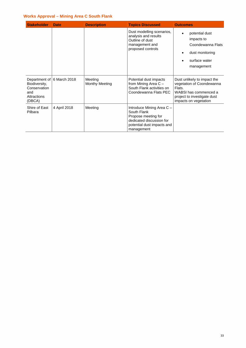
Works Approval – Mining Area C South Flank
33
Stakeholder Date Description Topics Discussed Outcomes
Dust modelling scenarios,analysis and resultsOutline of dustmanagement andproposed controls
· potential dustimpacts toCoondewanna Flats
· dust monitoring
· surface watermanagement
Department ofBiodiversity,ConservationandAttractions(DBCA)
6 March 2018 MeetingMonthy Meeting
Potential dust impactsfrom Mining Area C –South Flank activities onCoondewanna Flats PEC
Dust unlikely to impact thevegetation of CoondewannaFlats.WABSI has commenced aproject to investigate dustimpacts on vegetation
Shire of EastPilbara
4 April 2018 Meeting Introduce Mining Area C –South FlankPropose meeting fordedicated discussion forpotential dust impacts andmanagement
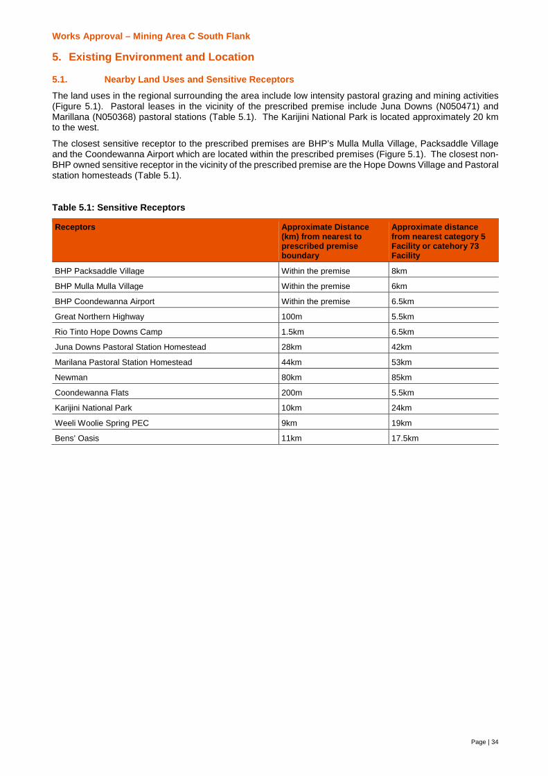
Works Approval – Mining Area C South Flank
Page | 34
5. Existing Environment and Location
5.1. Nearby Land Uses and Sensitive Receptors
The land uses in the regional surrounding the area include low intensity pastoral grazing and mining activities(Figure 5.1). Pastoral leases in the vicinity of the prescribed premise include Juna Downs (N050471) andMarillana (N050368) pastoral stations (Table 5.1). The Karijini National Park is located approximately 20 kmto the west.
The closest sensitive receptor to the prescribed premises are BHP’s Mulla Mulla Village, Packsaddle Villageand the Coondewanna Airport which are located within the prescribed premises (Figure 5.1). The closest non-BHP owned sensitive receptor in the vicinity of the prescribed premise are the Hope Downs Village and Pastoralstation homesteads (Table 5.1).
Table 5.1: Sensitive Receptors
Receptors Approximate Distance(km) from nearest toprescribed premiseboundary
Approximate distancefrom nearest category 5Facility or catehory 73Facility
BHP Packsaddle Village Within the premise 8km
BHP Mulla Mulla Village Within the premise 6km
BHP Coondewanna Airport Within the premise 6.5km
Great Northern Highway 100m 5.5km
Rio Tinto Hope Downs Camp 1.5km 6.5km
Juna Downs Pastoral Station Homestead 28km 42km
Marilana Pastoral Station Homestead 44km 53km
Newman 80km 85km
Coondewanna Flats 200m 5.5km
Karijini National Park 10km 24km
Weeli Woolie Spring PEC 9km 19km
Bens’ Oasis 11km 17.5km

!H
!H!H
!H
!H !H
!H!H
!H
!H!H
!
!
!
!
!
!
!
!!
!
!
!
!
!
!
!
!
Site 15
Site 12
Site 20
Hwy 1
Hwy 2Hwy 3
Hwy 4 Hwy 5Hwy 6
Hwy 7
Hwy 8Hwy 9
Hwy 10
HopeDownsCamp
Airport Mulla MullaVillage
PacksaddleVillage
Coondewanna Flats PEC
KarijiniNational
Park
JUNA DOWNSN050471
670,000
670,000
680,000
680,000
690,000
690,000
700,000
700,000
710,000
710,000
7,450
,000
7,450
,000
7,460
,000
7,460
,000
7,470
,000
7,470
,000
Liability BHPBIO does not warrant that this map is free from errors or omissions. BHPBIO shall not be in any way liable for loss, damage or injury to the user of this map or any other person or organisation consequent upon or incidental to the existence of errors or omissions on this map. This map has been compiled with data from numerous sources with different levels of reliability and is considered by the authors to be fit for its in tended purpose at the time of publication. However, it should be noted that the information shown may be subject to change and ultimately, map users are required to determine the suitability of use for any particular purpose.
Document Path: Y:\Jobs\A501_A1000\A780\3Project\A780_107_E_MAC_SouthernFlank_WorksApproval_SensitiveReceptors_Fig5.1_RevA.mxd
Date:Scale @ A4:
MINING AREA C - SOUTHERN FLANKWorks Approval Sensitive Receptors
0 2 4 6
Kilometres
5.1
±22/03/2018
BHP BILLITON IRON ORE
Figure :Project No:1:200,000
Checked:Prepared: M. LYTTLE
G. MANNINGA780/107 REV A
Revision: REV A Reviewed: K. FLOWERDEWCoordinate System: GDA 1994 MGA Zone 50
Projection: Transverse MercatorDatum: GDA 1994
MAC / Southern Flank ProposedPrescribed Premises Boundary (L7851)
! Sensitive Receptors!H High Value Ghost bat Caves
Juna Downs Pastoral LeasePriority Ecological CommunityKarijini National Park
HighwaysBHP RailRioTinto Rail
Works Approval – Mining Area C South Flank
Page | 36
5.2. Climate
Mining Area C is located in the Pilbara region of Western Australia, which experiences a semi-arid climate withtwo distinct seasons: a hot summer from October to April and a mild winter from May to September.
Climatic data from the Bureau of Meteorology’s (BoM) Newman weather station (Station Number 007176)indicates that peak rainfall occurs in the summer months between December and March with a smaller peak inMay and June. The mean monthly rainfall for Newman ranges from 4.9 millimetres (mm) in October to 77 mmin February with a mean annual rainfall of 310.7 mm (BoM, 2017).
Rainfall during summer months is strongly dominated by tropical cyclones and thunderstorm activity betweenNovember and March. Rainfall during May and June is the result of cold fronts moving across the south of theState that occasionally extends to the Pilbara.
Mean maximum temperatures range between 22°C to 29°C in winter and 32°C to 39°C during summer.Evaporation greatly exceeds rainfall in the region throughout the year and on a month-by-month basis sincethe mean annual pan evaporation rate at Mining Area C is estimated at 3,400 mm, which exceeds annualrainfall by around 3,100 mm, and average monthly pan evaporation rates vary between a minimum 160 mm inJune and a maximum 430 mm in December (Aquaterra, 2009).
The seasonal wind roses for Newman weather station show that the dominant annual wind directions aredistinctively north-westerly during the summer months and south-easterly during the winter months (PEL,2015). Spring also shows high north-westerly dominance, driven by land-sea temperature differences in thelead up to the summer months.
5.3. Geology
The Pilbara bioregion, where the Proposal is located, is situated in the south-eastern comer of the PilbaraCraton. The cratonic basement comprises Archaean granite-greenstone and is unconformably overlain by thelate Archaean to Early Proterozoic deposits of the Hamersley Basin. The Hamersley Basin can be divided intothree stratigraphic groups: the Fortescue, Hamersley and Turee Creek groups. Of these groups, the Fortescueand Hamersley groups outcrop in the immediate area Mining Area C.
The Hamersley Group is seen throughout the Hamersley Basin and forms the outcrop of Mining Area C. It is asedimentary sequence comprising banded iron formations (BIFs), shales and dolomites with minor felsicvolcanics and intrusive dolerite dykes and sills. The group contains both the Brockman and Marra Mamba Ironformations, which together host most of the known major iron ore deposits in the Pilbara region. The six lower-most formations of the Hamersley Group that exist within the area are listed below in order of increasing age:
1. Weeli Wolli Formation.2. Brockman Iron Formation. Ore mineralisation from the Packsaddle Range deposits is contained within
the Brockman Iron Formation, composed of a sequence of interbedded Banded Iron Formation, shales,siltstones and cherts. The four members comprising of the formation are:
§ Yandicoogina Shale Member (shale and BIF);
§ Joffre Member (BIF with minor shale bands);
§ Whaleback Shale Member (interbedded shale, chert and BIF); and
§ Dales Gorge Member (interbedded BIF and shale).
3. Mount McRae Shale (graphitic and chloritic shales interbedded with BIF). The Mount McRae Shale(~30 m thick) consists of alternating bands of black carbonaceous shale and chert and is commonlycapped with pyritic chert bands. The Mount McRae Shale forms the basal unit to the ore horizons inthe Brockman Iron Formation and contains a limited enriched ore zone. BHP Billiton Iron Ore informallysubdivides this lithology into five units based on lithology and pyrite content. Several zones within theunit contain abundant pyrite nodules, thus, the formation is commonly regarded as a significant AMDrisk throughout the Pilbara region.
4. Mount Sylvia Formation (shale, dolomite and BlF bands).The Mount Sylvia Formation (~2.5 Ma) has athickness of ~50 m in the vicinity of the town of Newman, WA, and consists of three BIFs separated byinterlayered shale and dolomite as well as small amounts of chert.
5. Wittenoom Formation. The Wittenoom formation is located stratigraphically above and is younger than(2.6 – 2.5 Ma) the Marra Mamba Formation. The Wittenoom Formation has been deeply eroded in thedevelopment area and is mostly covered by Tertiary Detritals. The formation is predominantly

Works Approval – Mining Area C South Flank
37
comprised of calcareous and manganiferous shales, cherts and dolomite and includes the followingmembers comprising:
§ Bee Gorge Member (calcareous shale and dolomite);
§ Paraburdoo Member (dolomite – karstic in part); and
§ West Angela Member (manganese-rich shale with minor BIF and chert bands).6. Marra Mamba Iron Formation. The Marra Mamba Iron Formation is approximately 205 m thick and is
the oldest formation (2.6 Ma) identified in the prescribed premise. It is comprised of a sequence of BIF,shales, siltstones and minor cherts. The Mount Newman Member hosts the bulk of the mineralisationassociated with the Marra Mamba Iron Formation Deposits. The formation is divided into the followingmembers:
§ Mount Newman Member (BIF with thin shale bands);
§ MacLeod Member (BIF with extensive interbedded shales and ‘podded’ BIF horizons); and
§ Nammuldi Member (cherty BIF with occasional shale bands).
5.4. Soils and Landform
Five land systems occur within the Mining Area C prescribed premises (Table 5.2). The dominant land systemspresent are the Newman and Boolgeeda land systems, comprising the plateaux, ridges, mountains and hillsand their associated drainage zones of this section of the Hamersley Range.
Table 5.2: Landsystems Present within the Prescribed Premises
Landsytem Description
Boolgeeda Stony plains with hard Spinifex grasslands or Mulga shrublands. The geology isquaternary colluvium
Newman Rugged jaspilite plateaux, ridges and mountains supporting hard spinifex grasslands.
Pindering Gravelly hardpan plains supporting groved mulga shrublands with hard and soft spinifex.
Platform Narrow, raised plains and highly dissected slopes on partly consolidated colluvium belowthe footslopes of hill systems such as Newman, relief mostly up to about 30 m butoccasionally considerably greater
Wannamunna Level alluvial plains with prominent grove patterns of vegetation and shallow loamy soilsover hardpan and broad internal drainage plains with deeper more clayey soils, relief upto 5 m. The system is found in south central parts of the survey area as broad flats withinthe Hamersley Ranges (Newman land system).
The prescribed premises occur within the Hamersley Plateaux Zone of the Fortescue Province of the WesternRegion of the soil-landscape zones of Western Australia (Tille, 2006). The dominant landform features withinthis zone are rocky ranges and hills and stony plains. Rugged hills, ridges, dissected plateaux and mountainsoccur on the basalt, BIF and sandstone of the Hamersley Basin, the most notable examples being theChichester and Hamersley ranges.
Soils of the Pilbara region have been defined and mapped at a scale of 1:2,000,000 by Bettenay et al. (1967).Three soil units occur within the Prescribed Premises: Fa13, Fb3 and Ja2.
· Soil Unit Fa13 is described as: “Ranges of banded jaspilite and chert along with shales, dolomites, andiron ore formations; some areas of ferruginous duricrust as well as occasional narrow winding valleyplains and steeply dissected pediments. This unit is largely associated with the Hamersley andOphthalmia Ranges. The soils are frequently stony and shallow and there are extensive areas withoutsoil cover: chief soils are shallow stony earthy loams (Um5.51) along with some (Uc5.11) soils on thesteeper slopes. Associated are (Dr2.33, Dr2.32) soils on the limited areas of dissected pediments,while (Um5.52) and (Uf6.71) soils occur on the valley plains.”
· Soil Unit Fb3 is described as: "High-level valley plains set in extensive areas of unit Fa13. There areextensive areas of pisolitic limonite deposits: principal soils are deep earthy loams (Um5.52) along withsmall areas of (Gn2.12) soils."
· Soil Unit Ja2 is described as: "This unit occupies the central position within the high-level valley plainsrepresented by unit Fb3: chief soils are earthy clays (Uf6.71) along with extensive areas of (Ug5.38)soils."

Works Approval – Mining Area C South Flank
38
5.5. Air Quality
The semi-arid landscape of the Pilbara is a naturally dusty environment with wind-blown dust a significantcontributor to ambient dust levels in the region. BHP Billiton has an ambient air quality monitoring network inplace in the vicinity of the inland Pilbara operations. In 2015 an assessment of the total suspended particlesand PM10 data from the network was undertaken to estimate the local background air quality. From the sixmonitoring sites, one (BG2) was considered representative of ambient conditions and was not expected to beinfluenced by existing mining activities. The BG2 site is located approximately 5 km south-east of the NewmanTownship. From the 2009 to 2012 catalogue of data, the year 2010 was recommended as reflective ofbackground conditions. The background PM10 concentration of 18 μg/m3 and a background TSPconcentration of 33 μg/m3 was considered to be reflective of the region. These were based on the 70thpercentile of PM10 and TSP concentrations in 2010 (PEL 2015a). Ongoing monitoring of backgroundparticulate matter levels from the BHP ambient air quality network surrounding Newman have shown thatbackground level are higher than the 70 µg/m3 typically around 3-6 times per annum.
5.6. Groundwater
The prescribed premises lies within the following two regional aquifers:1. Hamersley – Fractured Rock Aquifer: The Precambrian rocks of the Hamersley Basin are principally
volcanics, shales and iron formations. Groundwater is contained within fractures within these rocks.The groundwater level may be deep below the surface, and is generally fresh. The main use of thisaquifer is for mining and mine dewatering from iron ore mines. Bores have also been drilled for roadand railway construction. There will be increasing dewatering from the fractured rocks around iron oremines as the pits become deeper (DoW, 2015a).
2. Hamersley – Wittenoom Aquifer: The Wittenoom aquifer is distinguished as a separate aquifer systembecause the Wittenoom Dolomite is distinct from the other fractured rock aquifers in the HamersleyBasin, having karst development (solution cavities) and being overlain by a thick sequence of valleyfilled sediments consisting of pisolite, calcrete and alluvium. The Wittenoom Dolomite is the mostimportant aquifer in the province and underlies the main valleys in the Hamersley Range; it is highlytransmissive and high yielding where there is karst development. Water levels may be fairly deep. Thegroundwater is generally fresh. The aquifer has been developed for Tom Price and Marandoo watersupply and has been investigated at other localities. There is likely to be significant developmentpressure on this aquifer for supply to iron ore operations (DoW, 2015b).
The main regional aquifer at Mining Area C is the karstic Paraburdoo Dolomite of the Wittenoom Formation.This forms a high permeability zone at the base of the Northern Flank valley, and is the source of the majorityof the mine water supply. Above the dolomite, the valley has been filled with Tertiary age materials, includingcalcrete and possibly scree (or Channel Iron Deposits) originating from mineralised Brockman Iron Formationon the valley sides. Over much of the valley, the tertiary material comprises significant clay and silt of lowpermeability (Aquaterra, 2008).
Mining Area C is predominantly located in the upper reaches of the Weeli Wolli Creek system, which is atributary of the Fortescue River. The regional groundwater flow direction within the North and South FlankValleys is from west to east towards Weeli Wolli Spring, with outflow from the system occurring as both surfacewater flow and groundwater through-flow at the spring. Weeli Wolli Spring is formed by the convergence ofgroundwater flow on the narrow gap through the Packsaddle Range and shallow sub cropping/outcroppingbasement rock, causing groundwater levels to rise to the topographic surface (Aquaterra, 2008).
The depth to water across the area varies between 0 mbgl and over 100 mbgl, but typically the range acrossthe catchment is 15 – 60 mbgl. Generally, depth to water is lowest in the areas of Coondewanna Flats andWeeli Wolli Spring where surface water and groundwater flow concentrates. Depth to water is greatest in theupland areas
The majority of the groundwater recharge occurs via seepage from the Lake Robinson – which forms inCoondewanna Flats after inundation events. Enhanced recharge also occurs in the area of Weeli Wolli Springvia surface exposures of calcretes. Recharge occurs seasonally or periodically in response to high magnitudelow frequency rainfall events. On average, significant recharge to the groundwater system occurs annually atWeeli Wolli Spring and every four years at Coondewanna Flats. A limited amount of recharge also occurs fromdiffuse recharge over the entire catchment in response to seasonal rainfall events.
There are no public drinking water source areas within or adjacent to the prescribed premises.
Works Approval – Mining Area C South Flank
39
5.7. Surface water
The prescribed premises occurs in the sub-catchment of Weeli Wolli Creek, which is a tributary of the FortescueRiver. The Weeli Wolli Creek sub-catchment is further divided into three sub-catchments:
· Upper Weeli Wolli Creek sub-catchment (1,877 km2);
· Marillana Creek sub-catchment (2,050 km2); and
· Lower Weeli Wolli Creek sub-catchment (210 km2) - which receives flow from the above sub-catchments.
The Weeli Wolli Creek sub-catchment is flanked by the Coondewanna sub-catchment (862 km2), which is partof the Ashburton River catchment. Groundwater sometimes flows across the catchment divide between theUpper Weeli Wolli Creek sub-catchment and the Coondewanna sub-catchment (URS, 2014).
A number of unnamed perennial watercourses flow across the prescribed premises. The prescribed premisesalso intersects the northern-most section of Coondewanna Flats but is not within the boundary of theCoondewanna Flats Priority Ecological Community (PEC).
5.8. Flora and Vegetation
5.8.1.Vegetation
There are two vegetation associations (as mapped by Shepherd et al. (2002)) in the Mining Area C PrescribedPremise:
· Hamersley 18: Low woodland; mulga (Acacia aneura); and
· Hamersley 82: Hummock grasslands, low tree steppe; snappy gum over Triodia wiseana.
Botanical surveys identified 34 vegetation associations in the Mining Area C Prescribe Premises Boundary(Table 5.3, Onshore Environmental, 2017). At the complex level, vegetation within the Mining Area CPrescribed Premises is well represented and well reserved within the Pilbara bioregion.
No Threatened Ecological Communities (TECs) listed under the Environmental Protection BiodiversityConservation Act, 1999 (EPBC Act) or the Wildlife Conservation Act, 1950 (WC Act) have been identified withinthe Prescribed Premises. Two Priority Ecological Communities (PECs) occur within 20 km of the Mining AreaC –South Flank (Figure 1.1). DBCA (2017) priority listings described the PEC’s as:
· Coolibah-lignum flats: Eucalyptus victrix over Muehlenbeckia community Woodland or forest ofEucalyptus victrix (coolibah) over thicket of Duma florulenta (lignum) on red clays in run-on zones.Associated species include Eriachne benthamii, Themeda triandra, Aristida latifolia, Eulalia aurea andAcacia aneura. A series of subtypes have been identified: ·
o Priority 3 - Coolibah and mulga (Acacia aneura) woodland over lignum and tussock grasseson clay plains (Coondewanna Flats).
o Priority 1 - Coolibah woodlands over lignum (Duma florulenta) over swamp wandiree (LakeRobinson is the only known occurrence).
· Weeli Wolli Spring – Priority 1. Weeli Wolli Spring's riparian woodland and forest associations are unusualas a consequence of the composition of the understorey. The sedge and herbfield communities that fringemany of the pools and associated water bodies along the main channels of Weeli Wolli Creek have not beenrecorded from any other wetland site in the Pilbara.
Neither PEC occurs within the prescribed premise boundary.
A majority of the vegetation in the Mining Area C prescribed premises, was considered to be in Good or bettercondition. Vegetation in areas of higher relief, with restricted access by stock and supporting less palatableplant species, retained higher condition in the range of Excellent to Pristine. Vegetation condition declines toVery Good or Good on drainage lines and flood plains, as well as on areas where exploration activities haveoccurred or the impact of stock is greater. The major impact on lowland vegetation is the result of grazing bycattle, which has contributed to changes in native vegetation structure and composition, the introduction ofweed species, and surface instability.
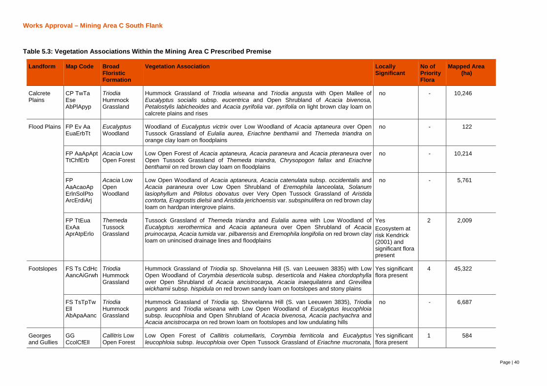
Works Approval – Mining Area C South Flank
Page | 40
Table 5.3: Vegetation Associations Within the Mining Area C Prescribed Premise
Landform Map Code BroadFloristicFormation
Vegetation Association LocallySignificant
No ofPriorityFlora
Mapped Area(ha)
CalcretePlains
CP TwTaEseAbPlApyp
TriodiaHummockGrassland
Hummock Grassland of Triodia wiseana and Triodia angusta with Open Mallee ofEucalyptus socialis subsp. eucentrica and Open Shrubland of Acacia bivenosa,Petalostylis labicheoides and Acacia pyrifolia var. pyrifolia on light brown clay loam oncalcrete plains and rises
no - 10,246
Flood Plains FP Ev AaEuaErbTt
EucalyptusWoodland
Woodland of Eucalyptus victrix over Low Woodland of Acacia aptaneura over OpenTussock Grassland of Eulalia aurea, Eriachne benthamii and Themeda triandra onorange clay loam on floodplains
no - 122
FP AaApAptTtChfErb
Acacia LowOpen Forest
Low Open Forest of Acacia aptaneura, Acacia paraneura and Acacia pteraneura overOpen Tussock Grassland of Themeda triandra, Chrysopogon fallax and Eriachnebenthamii on red brown clay loam on floodplains
no - 10,214
FPAaAcaoApErlnSolPtoArcErdiArj
Acacia LowOpenWoodland
Low Open Woodland of Acacia aptaneura, Acacia catenulata subsp. occidentalis andAcacia paraneura over Low Open Shrubland of Eremophila lanceolata, Solanumlasiophyllum and Ptilotus obovatus over Very Open Tussock Grassland of Aristidacontorta, Eragrostis dielsii and Aristida jerichoensis var. subspinulifera on red brown clayloam on hardpan intergrove plains.
no - 5,761
FP TtEuaExAaAprAtpErlo
ThemedaTussockGrassland
Tussock Grassland of Themeda triandra and Eulalia aurea with Low Woodland ofEucalyptus xerothermica and Acacia aptaneura over Open Shrubland of Acaciapruinocarpa, Acacia tumida var. pilbarensis and Eremophila longifolia on red brown clayloam on unincised drainage lines and floodplains
YesEcosystem atrisk Kendrick(2001) andsignificant florapresent
2 2,009
Footslopes FS Ts CdHcAancAiGrwh
TriodiaHummockGrassland
Hummock Grassland of Triodia sp. Shovelanna Hill (S. van Leeuwen 3835) with LowOpen Woodland of Corymbia deserticola subsp. deserticola and Hakea chordophyllaover Open Shrubland of Acacia ancistrocarpa, Acacia inaequilatera and Grevilleawickhamii subsp. hispidula on red brown sandy loam on footslopes and stony plains
Yes significantflora present
4 45,322
FS TsTpTwEllAbApaAanc
TriodiaHummockGrassland
Hummock Grassland of Triodia sp. Shovelanna Hill (S. van Leeuwen 3835), Triodiapungens and Triodia wiseana with Low Open Woodland of Eucalyptus leucophloiasubsp. leucophloia and Open Shrubland of Acacia bivenosa, Acacia pachyachra andAcacia ancistrocarpa on red brown loam on footslopes and low undulating hills
no - 6,687
Georgesand Gullies
GGCcolCfEll
Callitris LowOpen Forest
Low Open Forest of Callitris columellaris, Corymbia ferriticola and Eucalyptusleucophloia subsp. leucophloia over Open Tussock Grassland of Eriachne mucronata,
Yes significantflora present
1 584

Works Approval – Mining Area C South Flank
41
Landform Map Code BroadFloristicFormation
Vegetation Association LocallySignificant
No ofPriorityFlora
Mapped Area(ha)
ErmuThmbCya
Themeda sp. Mt Barricade (M.E. Trudgen 2471) and Cymbopogon ambiguus and VeryOpen Hummock Grassland of Triodia pungens on orange brown loam on upper gorges
GG CfEllFibAhDovmAshaCyaErmuThmb
Corymbia LowWoodland
Low Woodland of Corymbia ferriticola, Eucalyptus leucophloia subsp. leucophloia andFicus brachypoda over Open Shrubland of Acacia hamersleyensis, Dodonaea viscosasubsp. mucronata and Astrotricha hamptonii over Open Tussock Grassland ofCymbopogon ambiguus, Eriachne mucronata and Themeda sp. Mt Barricade on redbrown loam along clifflines and gorges
Yes significantflora present
5 3,685
GGTtErmuThmb EllChCfAtpGoroPl
ThemedaTussockGrassland
Tussock Grassland of Themeda triandra, Eriachne mucronata and Themeda sp. MtBarricade with Low Open Woodland of Eucalyptus leucophloia subsp. leucophloia,Corymbia hamersleyana and Corymbia ferriticola over High Shrubland of Acacia tumidavar. pilbarensis, Gossypium robinsonii and Petalostylis labicheoides on red brown sandyloam in narrowly incised rocky drainage lines
Yes significantflora present
2 1,030
Hill Crestsand UpperHill Slopes
HC TpTwTsEllChAarGooKeve
TriodiaHummockGrassland
Hummock Grassland of Triodia pungens, Triodia wiseana and Triodia sp. ShovelannaHill (S. van Leeuwen 3835) with Low Open Woodland of Eucalyptus leucophloia subsp.leucophloia and Corymbia hamersleyana over Low Shrubland of Acacia arida,Gompholobium oreophilum and Keraudrinia velutina subsp. elliptica on red brown loamon hills
no - 5,277
HC Tw AhEkkEgCh
TriodiaHummockGrassland
Hummock Grassland of Triodia wiseana with Shrubland of Acacia hamersleyensis andOpen Mallee of Eucalyptus kingsmillii subsp. kingsmillii, Eucalyptus gamophylla andCorymbia hamersleyana (mallee form) on red brown loam and silty loam on hill crests
no - 4,901
HC TwTsTpEllCh Ah
TriodiaHummockGrassland
Hummock Grassland of Triodia wiseana, Triodia sp. Shovelanna Hill (S. van Leeuwen3835) and Triodia pungens with Low Open Woodland of Eucalyptus leucophloia subsp.leucophloia and Corymbia hamersleyana over Open Shrubland of Acaciahamersleyensis on red brown clay loam on hill crests and upper hill slopes
no - 8,049
Hill SlopesandUndulatingLow Hills
HS AaAprErjpAmarCocf TwTp
Acacia LowWoodland
Low Woodland of Acacia aptaneura and Acacia pruinocarpa over Shrubland ofEremophila jucunda subsp. pulcherrima, Acacia marramamba and Codonocarpuscotinifolius over Open Hummock Grassland of Triodia wiseana and Triodia pungens onred brown loam on hill slopes
Yes significantflora present
2 715
HS TbrTwEll
TriodiaHummockGrassland
Hummock Grassland of Triodia brizoides and/or Triodia wiseana with Low OpenWoodland of Eucalyptus leucophloia subsp. leucophloia on brown sandy loam on steephill slopes
no - 12,977
HS TpAaApr
Triodia OpenHummockGrassland
Open Hummock Grassland of Triodia pungens with Low Open Woodland of Acaciaaptaneura and Acacia pruinocarpa over Open Shrubland of Eremophila fraseri, Acacia
no - 391

Works Approval – Mining Area C South Flank
42
Landform Map Code BroadFloristicFormation
Vegetation Association LocallySignificant
No ofPriorityFlora
Mapped Area(ha)
ErfrAmarSegl
marramamba and Senna glutinosa subsp. x luerssenii on red brown loam on undulatinghills
HS Tp EllSeggGrwhErll
TriodiaHummockGrassland
Hummock Grassland of Triodia pungens with Scattered Low Trees of Eucalyptusleucophloia subsp. leucophloia and Scattered Shrubs of Senna glutinosa subsp.glutinosa, Grevillea wickhamii subsp. hispidula and Eremophila latrobei subsp. latrobeion skeletal orange brown loam on stony hill slopes
no - 378
HS TsTw EgGrwhSeggAb
TriodiaHummockGrassland
Hummock Grassland of Triodia sp. Shovelanna Hill (S. van Leeuwen 3835) and Triodiawiseana with Very Open Mallee of Eucalyptus gamophylla over Open Shrubland ofGrevillea wickhamii subsp. hispidula, Senna glutinosa subsp. glutinosa and Acaciabivenosa on red brown sandy clay loam on hill slopes
no - 1,032
HS TsTwTpEllChAhiAaa
TriodiaHummockGrassland
Hummock Grassland of Triodia sp. Shovelanna Hill (S. van Leeuwen 3835), Triodiawiseana and Triodia pungens with Low Open Woodland of Eucalyptus leucophloiasubsp. leucophloia and Corymbia hamersleyana over Low Open Shrubland of Acaciahilliana and Acacia adoxa var. adoxa on red brown sandy loam on hill slopes
Yes significantflora present
4 44,324
HS TwTpTbrEll Ep
TriodiaHummockGrassland
Hummock Grassland of Triodia wiseana, Triodia pungens and Triodia brizoides with LowOpen Woodland of Eucalyptus leucophloia subsp. leucophloia over Open Mallee ofEucalyptus pilbarensis on red brown loam on steep hill slopes
no - 2,339
HS TwTpTsEllAprAaAanc
TriodiaHummockGrassland
Hummock Grassland of Triodia wiseana, Triodia pungens and Triodia sp. ShovelannaHill (S. van Leeuwen 3835) with Low Open Woodland of Eucalyptus leucophloia subsp.leucophloia over Open Shrubland of Acacia pruinocarpa, Acacia aptaneura and Acaciaancistrocarpa on red brown loam on plains and low hills
no - 1,304
MajorDrainageLines
MA EcrEvExApypAtpGoro TtEuaCyp
EucalyptusLow OpenForest
Low Open Forest of Eucalyptus camaldulensis subsp. refulgens, Eucalyptus victrix andEucalyptus xerothemica over High Shrubland of Acacia pyrifolia var. pyrifolia, Acaciatumida var. pilbarensis and Gossypium robinsonii over Open Tussock Grassland ofThemeda triandra, Eulalia aurea and Cymbopogon procerus on red brown clay loam onmajor drainage lines
Yes –ecosystem atrisk Kendrick(2001) andsignificant florapresent
2 3,970
MAAtpApypAseEcrThmbTtCyp
Acacia HighShrubland
High Shrubland of Acacia tumida var. pilbarensis, Acacia pyrifolia var. pyrifolia andAcacia sericophylla with Scattered Trees of Eucalyptus camaldulensis subsp. refulgensover Open Tussock Grassland of Themeda sp. Mt Barricade (M.E. Trudgen 2471),Themeda triandra and Cymbopogon procerus on brown loam and gravels on majordrainage channels
Yes -ecosystem atrisk Kendrick(2001)
- 255
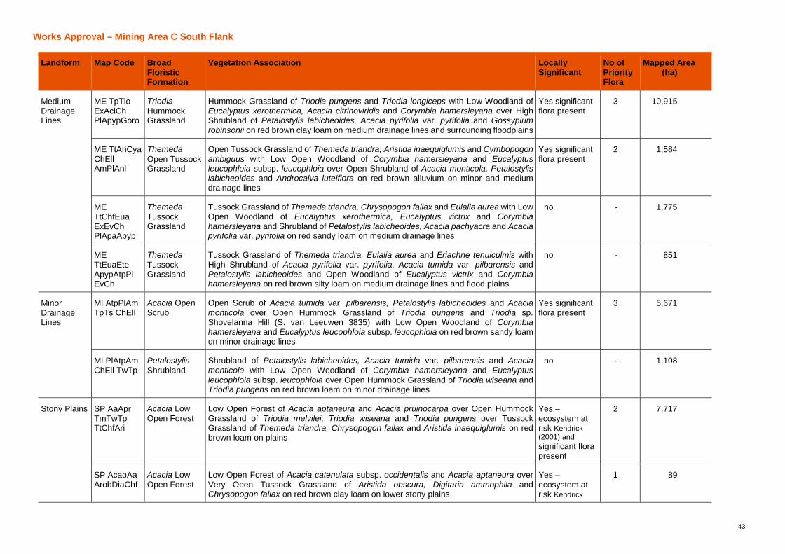
Works Approval – Mining Area C South Flank
43
Landform Map Code BroadFloristicFormation
Vegetation Association LocallySignificant
No ofPriorityFlora
Mapped Area(ha)
MediumDrainageLines
ME TpTloExAciChPlApypGoro
TriodiaHummockGrassland
Hummock Grassland of Triodia pungens and Triodia longiceps with Low Woodland ofEucalyptus xerothermica, Acacia citrinoviridis and Corymbia hamersleyana over HighShrubland of Petalostylis labicheoides, Acacia pyrifolia var. pyrifolia and Gossypiumrobinsonii on red brown clay loam on medium drainage lines and surrounding floodplains
Yes significantflora present
3 10,915
ME TtAriCyaChEllAmPlAnl
ThemedaOpen TussockGrassland
Open Tussock Grassland of Themeda triandra, Aristida inaequiglumis and Cymbopogonambiguus with Low Open Woodland of Corymbia hamersleyana and Eucalyptusleucophloia subsp. leucophloia over Open Shrubland of Acacia monticola, Petalostylislabicheoides and Androcalva luteiflora on red brown alluvium on minor and mediumdrainage lines
Yes significantflora present
2 1,584
METtChfEuaExEvChPlApaApyp
ThemedaTussockGrassland
Tussock Grassland of Themeda triandra, Chrysopogon fallax and Eulalia aurea with LowOpen Woodland of Eucalyptus xerothermica, Eucalyptus victrix and Corymbiahamersleyana and Shrubland of Petalostylis labicheoides, Acacia pachyacra and Acaciapyrifolia var. pyrifolia on red sandy loam on medium drainage lines
no - 1,775
METtEuaEteApypAtpPlEvCh
ThemedaTussockGrassland
Tussock Grassland of Themeda triandra, Eulalia aurea and Eriachne tenuiculmis withHigh Shrubland of Acacia pyrifolia var. pyrifolia, Acacia tumida var. pilbarensis andPetalostylis labicheoides and Open Woodland of Eucalyptus victrix and Corymbiahamersleyana on red brown silty loam on medium drainage lines and flood plains
no - 851
MinorDrainageLines
MI AtpPlAmTpTs ChEll
Acacia OpenScrub
Open Scrub of Acacia tumida var. pilbarensis, Petalostylis labicheoides and Acaciamonticola over Open Hummock Grassland of Triodia pungens and Triodia sp.Shovelanna Hill (S. van Leeuwen 3835) with Low Open Woodland of Corymbiahamersleyana and Eucalyptus leucophloia subsp. leucophloia on red brown sandy loamon minor drainage lines
Yes significantflora present
3 5,671
MI PlAtpAmChEll TwTp
PetalostylisShrubland
Shrubland of Petalostylis labicheoides, Acacia tumida var. pilbarensis and Acaciamonticola with Low Open Woodland of Corymbia hamersleyana and Eucalyptusleucophloia subsp. leucophloia over Open Hummock Grassland of Triodia wiseana andTriodia pungens on red brown loam on minor drainage lines
no - 1,108
Stony Plains SP AaAprTmTwTpTtChfAri
Acacia LowOpen Forest
Low Open Forest of Acacia aptaneura and Acacia pruinocarpa over Open HummockGrassland of Triodia melvilei, Triodia wiseana and Triodia pungens over TussockGrassland of Themeda triandra, Chrysopogon fallax and Aristida inaequiglumis on redbrown loam on plains
Yes –ecosystem atrisk Kendrick(2001) andsignificant florapresent
2 7,717
SP AcaoAaArobDiaChf
Acacia LowOpen Forest
Low Open Forest of Acacia catenulata subsp. occidentalis and Acacia aptaneura overVery Open Tussock Grassland of Aristida obscura, Digitaria ammophila andChrysopogon fallax on red brown clay loam on lower stony plains
Yes –ecosystem atrisk Kendrick
1 89
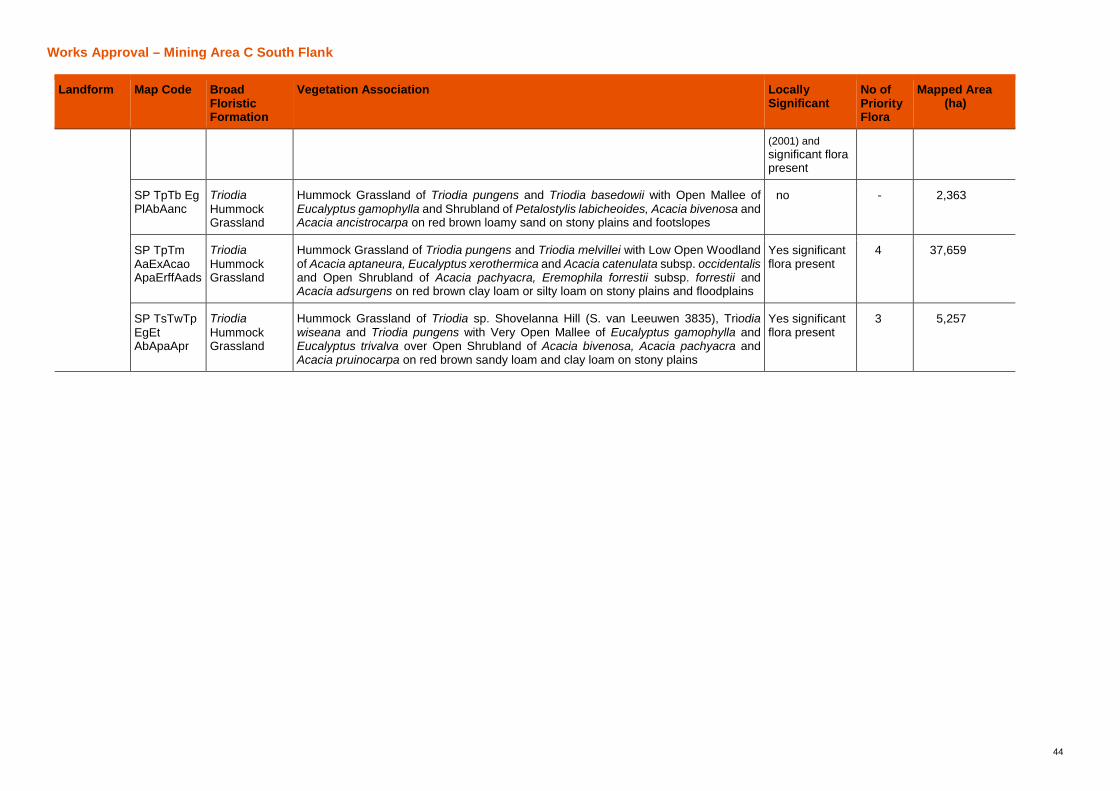
Works Approval – Mining Area C South Flank
44
Landform Map Code BroadFloristicFormation
Vegetation Association LocallySignificant
No ofPriorityFlora
Mapped Area(ha)
(2001) andsignificant florapresent
SP TpTb EgPlAbAanc
TriodiaHummockGrassland
Hummock Grassland of Triodia pungens and Triodia basedowii with Open Mallee ofEucalyptus gamophylla and Shrubland of Petalostylis labicheoides, Acacia bivenosa andAcacia ancistrocarpa on red brown loamy sand on stony plains and footslopes
no - 2,363
SP TpTmAaExAcaoApaErffAads
TriodiaHummockGrassland
Hummock Grassland of Triodia pungens and Triodia melvillei with Low Open Woodlandof Acacia aptaneura, Eucalyptus xerothermica and Acacia catenulata subsp. occidentalisand Open Shrubland of Acacia pachyacra, Eremophila forrestii subsp. forrestii andAcacia adsurgens on red brown clay loam or silty loam on stony plains and floodplains
Yes significantflora present
4 37,659
SP TsTwTpEgEtAbApaApr
TriodiaHummockGrassland
Hummock Grassland of Triodia sp. Shovelanna Hill (S. van Leeuwen 3835), Triodiawiseana and Triodia pungens with Very Open Mallee of Eucalyptus gamophylla andEucalyptus trivalva over Open Shrubland of Acacia bivenosa, Acacia pachyacra andAcacia pruinocarpa on red brown sandy loam and clay loam on stony plains
Yes significantflora present
3 5,257
Works Approval – Mining Area C South Flank
Page | 45
5.8.2.Flora
No flora species listed under the EPBC Act or the Wildlife Conservation Act 1950 (WC Act) have been identifiedwithin the prescribed premises. Twelve flora species listed as priority flora by the Department of Biodiversity,Conservation and Attractions (DBCA) occur within the Mining Area C prescribed premise boundary :
· Acacia bromilowiana (Priority 4);
· Aristida jerichoensis supsp. spinulifera (Priority 3);
· Aristida lazaridis (Priority 2);
· Eremophila magnifica subsp. magnifica (Priority 4);
· Goodenia nuda: Priority 4;
· Grevillea saxicola (Priority 3);
· Nicotiana umbratica (Priority 3);
· Rhagodia sp. Hamersley (M. Trudgen 17794) (Priority 3);
· Rostellularia adscendens var. latifolia (Priority 3);
· Sida sp. Barlee Range (S. van Leeuwen 1642) (Priority 3);
· Themeda sp. Hamersley Station (M.E. Trudgen 11431): Priority 3; and
· Triodia sp. Mt Ella (M.E. Trudgen 12739) (Priority 3) ;
Twenty three introduced flora species have been recorded within the prescribed premises boundary (Onshore,2016). None of these taxa are listed as Declared Pests under the Biosecurity and Agriculture Management Act2007 (BAM Act).
5.9. Ecological Communities
5.9.1.Coondewanna Flats PEC
Coondewanna Flats is located directly south west of Mining Area C and is the terminus of an internally drainingcatchment which extends to the west and has an overall catchment area of approximately 86,000 ha (AQ2,2016). Coondewanna Flats occupies an area of about 3,600 hectares (ha) (defined by the 690 m AustralianHeight Datum [AHD] land surface contour) and is bounded by hills and ranges including Mt Robinson (southeast), The Governor (south), Packsaddle Range (north) and Mt Meharry (west). Elevations range from 690 mAHD near the margins, to 686 m AHD at its lowest points, while the surrounding hills rise to over 1,200 m AHD.
The hydrostratigraphy of Coondewanna Flats includes low to moderate permeability Tertiary detritals overlyingan unconfined aquifer comprising calcrete and dolomite. The calcrete layer is extensive at a depth of about 16to 20 mbgl. This is underlain by low to high permeability basement of the Wittenoom Formation. The watertable occurs at a depth of approximately 18-24 mbgl; with the shallowest depth to water corresponding with thelowest elevation portion of the Flats near the south-west margin. Groundwater level gradients across the Flatsare low, however aquifer connectivity across the surface water catchment divide enables groundwater outflowinto the Northern Flank (MAC) and South Flank valleys to the east. A southwest-northeast trending dyke actsas a partial (low flow) groundwater flow barrier near the eastern edge of the Flats (AQ2, 2016).
An ecohydrological conceptualisation of the Coondewanna Flats (AQ2 and Equinox 2016) identified thefollowing three discrete ecohydrological system elements:
· Woodland vegetation communities dominated by Acacia aptaneura and Eucalyptus victrix;
· Soil Water Reservoir comprising of the water resources contained in the unsaturated zone (vadose zone),consisting of deep, fine textured sediments; and
· Groundwater Reservoir comprising of the groundwater resources contained in the saturated alluvial aquiferand underlying dolomite aquifer beneath the vadose zone.
These elements are linked to each other and the broader environment by the following processes:
· Periodic inundation of Coondewanna Flats by flood waters from the surrounding catchment;

Works Approval – Mining Area C South Flank
46
· Local scale redistribution of surface water within Coondewanna Flats as mediated by microtopography andareas of focussed surface water accumulation which occur at the Lake Robinson depression and near thesouthwest margin of Coondewanna Flats;
· Infiltration of water into the soil profile during flood events which replenishes soil water approximately threeout of four years and the groundwater system approximately one in four years;
· Transpiration by:
o Major tree species Eucalyptus victrix (which has a deep rooted species which may extract soilwater at depths of up to approximately 15 mbgl) and A. aptaneura (which has a shallow rootsystem with roots confined to 5 mbgl); and
o Under-storey vegetation (i.e. shallow rooted tussock grasses and Duma florulenta),
· Evaporation from bare soil and from ephemerally ponded water; and
· Outflow of groundwater from Coondewanna Flats to the east, into the Northern and South Flank Valleysrespectively (Note: there is minimal lateral inflow of groundwater to Coondewanna Flats from thesurrounding landscape due to low hydraulic gradients).
Approximately 2,990 ha of Coondewanna Flats contains the DBCA listed PEC ‘Coolibah-lignum flats vegetation(Section 5.8.1). The deep sediments of Coondewanna Flats are of key importance to the Coondewanna FlatsPEC as they provide significant inter-annual plant available water storage for the major tree species Eucalyptusvictrix which adopts a drought avoidance strategy, by maintaining access to relatively moist soil throughout theyear. In contrast Acaiac aptaneura adopts a drought tolerance strategy, by becoming quasi-dormant duringprolonged dry conditions (AQ2, 2016).
A number of studies addressing aspects of the ecohydrology of Coondewanna Flats have been completed inthe past decade, and more recently a considerable volume of monitoring data has been collected. Thesestudies have included a hydro-environmental assessment, monitoring of regional bores, analysis of tree waterchemistry and leaf water potential, and development of an ecohydrological conceptual model. A summary ofkey components of the conceptual ecohydrological model is as follows:
· It is an internally draining system relying on surface water runoff from the surrounding catchments.
· Surface water flows typically reach the Coondewanna Flats three out of every four years to replenish thesoil moisture in the unsaturated zone, even when groundwater recharge does not occur. Groundwater isgenerally 20 m below ground level (mbgl).
· The vegetation communities are considered unlikely to rely on groundwater as:
o There is abundant water in the soil profile to support the community for extended periods of time.
o The depth to groundwater is beyond the range commonly associated with groundwaterdependence.
o Soil matric-potential and soil water chemistry indicate plant water abstraction from 0 to 5 mbgl and6 to 15 mbgl.
o Measured predawn leaf water potentials for all species are negative. Changes in leaf waterpotential have reflected changes in soil moisture and matric pressure.
· The estimated soil-water reservoir could sustain the vegetation community for a drought period ofapproximately nine years.
5.9.2.Weeli Wolli Spring PEC
The Weeli Wolli Spring area is recognised as having multiple ecological values that collectively contribute to itsDBCA listing as a Priority 1 Ecological Community. The community is described by DBCA (2017) as follows:
“riparian woodland and forest associations are unusual as a consequence of the composition of theunderstorey. The sedge and herbfield communities that fringe many of the pools and associated water bodiesalong the main channels of Weeli Wolli Creek have not been recorded from any other wetland site in the Pilbara.The spring and creekline are also noted for their relatively high diversity of stygofauna and this is probablyattributed to the large-scale calcrete and alluvial aquifer system associated with the creek. The valley of WeeliWolli Spring also supports a very rich microbat assemblage including a threatened species”.
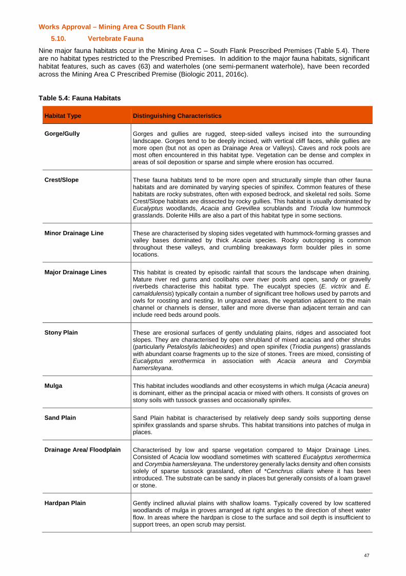
Works Approval – Mining Area C South Flank
47
5.10. Vertebrate Fauna
Nine major fauna habitats occur in the Mining Area C – South Flank Prescribed Premises (Table 5.4). Thereare no habitat types restricted to the Prescribed Premises. In addition to the major fauna habitats, significanthabitat features, such as caves (63) and waterholes (one semi-permanent waterhole), have been recordedacross the Mining Area C Prescribed Premise (Biologic 2011, 2016c).
Table 5.4: Fauna Habitats
Habitat Type Distinguishing Characteristics
Gorge/Gully Gorges and gullies are rugged, steep-sided valleys incised into the surroundinglandscape. Gorges tend to be deeply incised, with vertical cliff faces, while gullies aremore open (but not as open as Drainage Area or Valleys). Caves and rock pools aremost often encountered in this habitat type. Vegetation can be dense and complex inareas of soil deposition or sparse and simple where erosion has occurred.
Crest/Slope These fauna habitats tend to be more open and structurally simple than other faunahabitats and are dominated by varying species of spinifex. Common features of thesehabitats are rocky substrates, often with exposed bedrock, and skeletal red soils. SomeCrest/Slope habitats are dissected by rocky gullies. This habitat is usually dominated byEucalyptus woodlands, Acacia and Grevillea scrublands and Triodia low hummockgrasslands. Dolerite Hills are also a part of this habitat type in some sections.
Minor Drainage Line These are characterised by sloping sides vegetated with hummock-forming grasses andvalley bases dominated by thick Acacia species. Rocky outcropping is commonthroughout these valleys, and crumbling breakaways form boulder piles in somelocations.
Major Drainage Lines This habitat is created by episodic rainfall that scours the landscape when draining.Mature river red gums and coolibahs over river pools and open, sandy or gravellyriverbeds characterise this habitat type. The eucalypt species (E. victrix and E.camaldulensis) typically contain a number of significant tree hollows used by parrots andowls for roosting and nesting. In ungrazed areas, the vegetation adjacent to the mainchannel or channels is denser, taller and more diverse than adjacent terrain and caninclude reed beds around pools.
Stony Plain These are erosional surfaces of gently undulating plains, ridges and associated footslopes. They are characterised by open shrubland of mixed acacias and other shrubs(particularly Petalostylis labicheoides) and open spinifex (Triodia pungens) grasslandswith abundant coarse fragments up to the size of stones. Trees are mixed, consisting ofEucalyptus xerothermica in association with Acacia aneura and Corymbiahamersleyana.
Mulga This habitat includes woodlands and other ecosystems in which mulga (Acacia aneura)is dominant, either as the principal acacia or mixed with others. It consists of groves onstony soils with tussock grasses and occasionally spinifex.
Sand Plain Sand Plain habitat is characterised by relatively deep sandy soils supporting densespinifex grasslands and sparse shrubs. This habitat transitions into patches of mulga inplaces.
Drainage Area/ Floodplain Characterised by low and sparse vegetation compared to Major Drainage Lines.Consisted of Acacia low woodland sometimes with scattered Eucalyptus xerothermicaand Corymbia hamersleyana. The understorey generally lacks density and often consistssolely of sparse tussock grassland, often of *Cenchrus ciliaris where it has beenintroduced. The substrate can be sandy in places but generally consists of a loam gravelor stone.
Hardpan Plain Gently inclined alluvial plains with shallow loams. Typically covered by low scatteredwoodlands of mulga in groves arranged at right angles to the direction of sheet waterflow. In areas where the hardpan is close to the surface and soil depth is insufficient tosupport trees, an open scrub may persist.
Works Approval – Mining Area C South Flank
48
Eleven significant fauna species have been identified within the Prescribed Premises:
· Anilios ganei, (Pilbara Flat-headed Blind-snake): DBCA Priority 1;
· Apus pacificus (Fork-tailed Swift):EPBC Act Migratory, WC Act Migratory
· Dasyurus hallucatus (Northern Quoll):EPBC Act Endangered, WC Act Vulnerable;
· Falco hypoleucos (Grey Falcon):WC Act - Vulnerable;
· Falco peregrinus (Peregrine Falcon): WC Act Schedule 7;
· Liasis olivaceus subsp barroni (Pilbara Olive Python): EPBC Act Vulnerable, WC Act Vulnerable;
· Macroderma gigas (Ghost Bat): EPBC Act Vulnerable, WC Act Vulnerable;
· Merops ornatus (Rainbow Bee-eater): EPBC Act Migratory, WC Act Schedule 5;
· Pseudomys chapmani (Western Pebble-mound Mouse): DBCA Priority 4;
· Rhinonicteris aurantia (Pilbara Leaf-nosed Bat): EPBC Act Vulnerable; WC Act Vulnerable; and
· Underwoodisaurus seorsus (Pilbara Barking Gecko): DBCA Priority 2.
5.11. Subterranean Fauna
5.11.1. Stygofauna
Suitable habitat for stygofauna is hosted below water table within the enriched units of the Marra Mamba IronFormation, West Angelas units of the Wittenoom Formation, calcrete aquifers around Weeli Wolli Spring andthe Tertiary Detritals. Large areas of habitat remain outside the impact footprint including tertiary detritals invalleys to the south and west of South Flank, calcrete aquifers downstream of Weeli Wolli spring and aquifersassociated with Ben’s Oasis. Tertiary detritals can range from coarse sand and gravels with abundant porespace through to clay rich layers with microscopic voids and low habitat availability. Similarly calcretes canrange from vuggy material with significant pore space to crystalline deposits with very little pore space.Connection between voids in calcretes is variable and can be created during formation or by chemicaldissolution post-deposition. Mapping of widespread surrogate stygofauna within the Upper Weeli Wolli andCoondewanna catchments suggests that there are few barriers to movement for stygofauna.
Of the 27 species recorded in the prescribed premise and adjacent area, ten species are known only from thearea. For three species (Nr Epactophenes sp B01, Dussartcyclops sp B01 and Bathynella sp 2) the impactsfrom Mining Area C are uncertain. The five potentially restricted species at South Flank: Prethopalpus sp. B15,Prethopalpus julianneae, Philosciidae sp. B03, nr Andricophiloscia sp. B16 and Parajapygidae DPL024 wererecorded within the pit area. Given that habitat connectivity along Weeli Wolli Creek is likely to be high for allstygofaunal species, the potential conservation threat to all four species is considered to be low.
5.11.2. Troglofauna
The geology of the prescribed premises comprises four habitat types relevant to troglofauna. These are‘hardcap zone’, detritals, mineralised rock and BIF host rock.
The hardcap zone, formed from continued weathering of the surface of the deposits and surroundinglandscape, constitutes a semi-continuous carapace across the ranges. The formation of hardcap is not limitedto a particular rock type and has been observed on unconsolidated sediments, BIF and ore (Crowe, 2012). Thiszone can be extremely variable in texture and is known to contain frequent voids and cavities. Cavities on ascale of metres are occasionally observed during drilling and mining. Hardcap formation is usually strongestnear the surface and often grades into semi-hardcap and then unaltered rock with depth. This stratum isconsidered to provide important habitat for troglofauna.
The detritals can be divided into Recent Quaternary detritals and three classes of Tertiary detritals. Quaternarydetritals usually comprise a mix of ore and shale in a silty matrix. The deepest Tertiary detrital class consistsof haematite conglomerate or silt and clay, with limited capacity to support troglofauna. The middle Tertiarydetrital class consists of vuggy breccia, sand and calcrete that are suitable for troglofauna, together with lensesof clay that are not. The upper Tertiary detrital class consists of gravelly siltstone and siltstone that are likely toprovide troglofauna habitat.
The mineralised rock that is BIF contains voids and cavities as a result of weathering; it usually providesimportant troglofauna habitat. This mineralised BIF is a target for mining when iron ore levels within it are high,

Works Approval – Mining Area C South Flank
49
although it may also provide suitable habitat for troglofauna when ore concentrations are below commercialgrade.
The BIF host rock, precursor to iron ore, consists of finely bedded chert, iron oxides and silicates. The textureof this rock type is fine-grained and dense, with few to no voids and essentially no intergranular pore spaces.Interbedded within the iron formation are shales and cherts that can form bands up to 40 m thick. The shalesand cherts are similarly non-porous. Thus, it is unusual for BIF host rock to contain significant troglofaunahabitat.
A total of 3,585 specimens of troglofauna have been collected in the Mining Area C prescribed premise. Thesespecimens represent at least 126 species from 19 orders (Bennelogia 2016). Insects were numericallydominant, and schizomids were also relatively common. Most species, however, occurred at very lowabundance, and 49 species were represented by only one specimen (singleton). Detailed three dimensionalhabitat assessments have been undertaken for all species potentially restricted to areas of impact. Thesehabitat assessments suggest that most species (33 of the 41 potentially restricted species) are not restrictedto potential areas of impact. There is uncertainty around the remaining eight species due to lack of knowledgeabout the habitats in which these species occur or if they are actually even true troglofauna species. Given thatspecies records and habitat assessments suggest that the troglofauna species have, or likely have, distributionsthat extend beyond the proposed impact assessment areas and there are no major geological features likelyto restrict distributions of troglofauna

Works Approval – Mining Area C South Flank
Page | 50
6. Environmental Management Framework
6.1. Corporate Level Plans and Procedures
The management of the environmental aspects of BHP’s operations for the Project are managed under thecompany’s AS/NZS ISO 14001:2016 certified Environmental Management System (EMS). The EMS describesthe organisational structure, responsibilities, practices, processes and resources for implementing andmaintaining environmental objectives at all BHP sites.
Additionally, operational controls for environmental management for the mine are guided by BHP’s Chartervalues. The Charter Values outline a commitment to develop, implement and maintain management systemsfor sustainable development that drive continual improvement and set and achieve targets that promoteefficient use of resources. In order to give effect to the Charter Values, a series of “Our Requirements” (formerlyGroup Level Documents) have been developed.
BHP has also developed a Sustainable Development Policy for its Iron Ore operations. The SustainableDevelopment Policy outlines a commitment to setting objective and targets to achieve sustainable outcomesand to continually improve our performance.
To support these documents BHP has an internal Project Environmental and Aboriginal Heritage Review(PEAHR) system. The purpose of the system is to manage implementation of environmental, Aboriginalheritage, land tenure and legal commitments prior to and during land disturbance. All ground disturbanceactivities will meet the requirements of the PEAHR system.
6.2. Premises Level Plans and Procedures
At Mining Area C and South Flank, MS 1072 and Licence L7851/2002/6 govern environmental management.Table 6.1 outlines the five management plans required by MS1 072.
All personnel carrying out works associated with clearing activities are required to comply with the SustainableDevelopment Policy, the MS 1072 (and associated management plans), Environmental Licence L7851/2002/6,the PEAHR system and any other relevant legislative and licensing requirements.
Table 6.1: MS 1072 Management Plans
Condition Reference Management Plan required Environmental Aspects
3 Compliance Assessment Plan Compliance
5 Cultural Heritage Management Plan Social Surroundings
Heritage
6 Water Management Environmental Plan Hydrological Processes and Vegetation
Coondewanna Flats PEC
Weeli Wolli Spring PEC
Bens Oasis
7 Ghost Bat Environmental Management Plan Terrestrial Fauna
Ghost Bat
9 Mine Closure Plan Rehabilitation

Works Approval – Mining Area C South Flank
Page | 51
7. Environmental Impact AssessmentBHP has conducted multiple environmental risk assessments for the proposed mining activities for the Mine.This includes identifying all environmental sources of risk, the risk pathways, and any impacts likely to directlyor indirectly arise from the proposed mining activities. The aim of the risk assessment is to generate acomprehensive list of the activities and or infrastructure and their potential risks to impact on the environmentand the public.
For every risk identified, an assessment of the likelihood and consequence was undertaken to determine thepre-treated level of risk using the following risk assessment criteria provided in DWER (2017) GuidanceStatement Risk Assessments. Following the evaluation and assessment of the pre-treated level of risk,measures used to treat the risk, using a risk reduction hierarchy, have been used to demonstrate that residualrisks are reduced (Attachment 8).
7.1. Category 5 Processing Infrastructure
The following environmental factors associated with the proposed processing infrastructure that requirespecific management strategies include:
· Air Quality;
· Treated Waste Water; and
· Surface water.
Other environmental factors assessed include atmospheric gases, amenity and surface water.
7.1.1.Air Quality
Dispersion ModellingBHP commissioned air quality modelling to predict the potential impacts of the Mining Area C – South Flank onthe local and regional air quality (Attachment 7). The study included the assessment of dust particles as PM10
and total suspended particles (TSP). Dispersion modelling was conducted using the CALPUFF dispersionmodel combined with the Weather Research and Forecasting (WRF) Model for generation of meteorologicalinputs. Background particulate emissions were determined from monitoring data collected at a suitablebackground location near Newman. The background air quality applied to each scenario was PM10
concentration of 18µg/m3 and TSP of concentration of 33 μg/m3 (Section 5.5).
The modelling was conducted for a number of scenarios to assess the ground-level impact of the emissionsfrom Mining Area C and South Flank. These included prediction of ground level impact from the South Flankdevelopment in isolation including background (PEL, 2016), the predictions of ground level impact of miningthe 14 deposits at Mining Area C (PEL, 2015b) and a cumulative assessment of impacts of operations at MiningArea C, South flank and background (PEL, 2016). The modelled scenarios utilised the year of mining with thehighest movement of tonnes of ore and waste in the closest proximity to the sensitive receptors (Section 5.1).Table 7.1 outlies the inventory of dust sources and emission estimates for Mining Area C – South Flank.
The Mt Whaleback operations in Newman have a Part V licence that stipulates a value of 70 µg/m3, averagedover 24 hours for PM10. This value has been utilised for assessment of significance of potential impacts to airquality. The particulate matter composition and background regional particulate matter concentrations for MtWhaleback are similar in nature to those expected for Mining Area C.
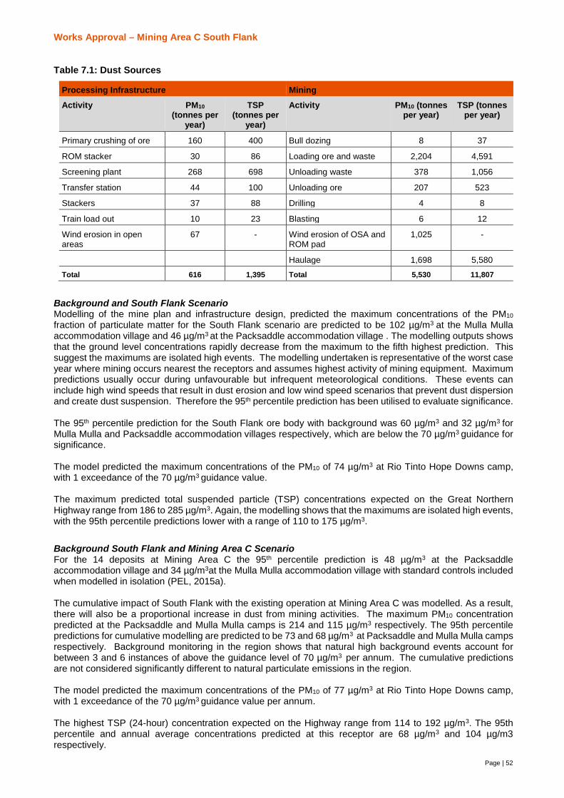
Works Approval – Mining Area C South Flank
Page | 52
Table 7.1: Dust Sources
Processing Infrastructure Mining
Activity PM10(tonnes per
year)
TSP(tonnes per
year)
Activity PM10 (tonnesper year)
TSP (tonnesper year)
Primary crushing of ore 160 400 Bull dozing 8 37
ROM stacker 30 86 Loading ore and waste 2,204 4,591
Screening plant 268 698 Unloading waste 378 1,056
Transfer station 44 100 Unloading ore 207 523
Stackers 37 88 Drilling 4 8
Train load out 10 23 Blasting 6 12
Wind erosion in openareas
67 - Wind erosion of OSA andROM pad
1,025 -
Haulage 1,698 5,580
Total 616 1,395 Total 5,530 11,807
Background and South Flank ScenarioModelling of the mine plan and infrastructure design, predicted the maximum concentrations of the PM10
fraction of particulate matter for the South Flank scenario are predicted to be 102 µg/m3 at the Mulla Mullaaccommodation village and 46 µg/m3 at the Packsaddle accommodation village . The modelling outputs showsthat the ground level concentrations rapidly decrease from the maximum to the fifth highest prediction. Thissuggest the maximums are isolated high events. The modelling undertaken is representative of the worst caseyear where mining occurs nearest the receptors and assumes highest activity of mining equipment. Maximumpredictions usually occur during unfavourable but infrequent meteorological conditions. These events caninclude high wind speeds that result in dust erosion and low wind speed scenarios that prevent dust dispersionand create dust suspension. Therefore the 95th percentile prediction has been utilised to evaluate significance.
The 95th percentile prediction for the South Flank ore body with background was 60 µg/m3 and 32 µg/m3 forMulla Mulla and Packsaddle accommodation villages respectively, which are below the 70 µg/m3 guidance forsignificance.
The model predicted the maximum concentrations of the PM10 of 74 µg/m3 at Rio Tinto Hope Downs camp,with 1 exceedance of the 70 µg/m3 guidance value.
The maximum predicted total suspended particle (TSP) concentrations expected on the Great NorthernHighway range from 186 to 285 µg/m3. Again, the modelling shows that the maximums are isolated high events,with the 95th percentile predictions lower with a range of 110 to 175 µg/m3.
Background South Flank and Mining Area C ScenarioFor the 14 deposits at Mining Area C the 95th percentile prediction is 48 µg/m3 at the Packsaddleaccommodation village and 34 µg/m3at the Mulla Mulla accommodation village with standard controls includedwhen modelled in isolation (PEL, 2015a).
The cumulative impact of South Flank with the existing operation at Mining Area C was modelled. As a result,there will also be a proportional increase in dust from mining activities. The maximum PM10 concentrationpredicted at the Packsaddle and Mulla Mulla camps is 214 and 115 µg/m3 respectively. The 95th percentilepredictions for cumulative modelling are predicted to be 73 and 68 µg/m3 at Packsaddle and Mulla Mulla campsrespectively. Background monitoring in the region shows that natural high background events account forbetween 3 and 6 instances of above the guidance level of 70 µg/m3 per annum. The cumulative predictionsare not considered significantly different to natural particulate emissions in the region.
The model predicted the maximum concentrations of the PM10 of 77 µg/m3 at Rio Tinto Hope Downs camp,with 1 exceedance of the 70 µg/m3 guidance value per annum.
The highest TSP (24-hour) concentration expected on the Highway range from 114 to 192 µg/m3. The 95thpercentile and annual average concentrations predicted at this receptor are 68 µg/m3 and 104 µg/m3respectively.
Works Approval – Mining Area C South Flank
53
Vegetation and DustDust associated with iron ore mining in the Pilbara is generally chemically inert (Butler, 2009; Turner, 2013).Any potential impacts on plants are likely to be:
· physical, including leaf abrasion,
· blocking of stomata and
· increased absorption of incident radiation, which in turn can elevate leaf temperature and negatively impacton photosynthetic processes and transpiration loss.
The susceptibility of vegetation to dust deposition is dependent on individual plant traits such as leaf hairiness,petiole length and plant height. (Butler, 2009). These physical effects tend to be proportional to the amount ofdust that vegetation is exposed to, the plant structures and the size of the dust particles (i.e. the higher the dustloading and the smaller the particle size, then the higher the risk) (Grierson, 2015).
Long-term observations of vegetation in close proximity to other mine sites across the Hamersley Range havedemonstrated repeatedly the overall resilience of vegetation to extremely high levels of dust exposure. Plantscoloured orange with dust accumulation for several years can survive and not display detectable negativeimpacts to the plants function (Butler 2009). This in part because plants in arid environments mainly grow inresponse to high rainfall and have very low metabolic rates outside of these periods. Growth periods alsocoincide with when (i) foliage is washed clean by rainfall and (ii) the lowest level of dust emissions due todamping down of the environment.
There is low risk of increased dusting to the vegetation forming the two subtypes of the Coondewanna FlatsPEC. Studies in the Pilbara on a range of species suggest that dust should it accumulate it is unlikely to impactvegetation function (Grierson, 2015).
Terrestrial Fauna and DustVegetation clearing, mining, hauling and vehicle movements will result in an increase in airborne particulatematter. Dust can indirectly affect fauna by altering the structure and composition of native vegetation. A resultof this could be a decline in vegetation quality, although no prior studies have been able to detect a significantadverse impact of airborne dust on plant function in the Pilbara (Grierson, 2015). If vegetation was to beaffected this could impact faunal assemblages by reducing both food and habitat resources.
Ghost Bats detect prey via sound, they also have excellent vision and it is possible that high dust levels couldirritate their eyes or reduce vision and affect their ability to capture prey. The dust modelling indicates thathigh dust events are likely at certain locations and times; however, a low risk rating is predicted for themajority of the year.
Continued implementation of existing dust suppression strategies will result in additional impacts to vertebratefauna from dust being minor.
Air Quality Management StrategiesThe following processing infrastructure dust controls will be adopted:
· Conveyor transfer chutes will be enclosed;
· Automated dust suppression water cannons will be installed at the stockyard to wet the stockpiles andsurrounding areas;
· Dust suppression fogging systems will be located on the ROM Bin, product screening, scalping and crushingbuildings at discharge from screens and crushers;
· Covers and/or hoods installed in PC1, PC2 andOHP3;
· The OLC and OHP3 will have Bulk Ore Conditioning (BOC) systems to control the moisture in the ore bytargeting the optimum moisture level to prevent dust and blockage issues;
· Measurement of real time ore moisture using Low Frequency Microwave Moisture Analysis throughout theprocess. The analysis will be located on the OLC (411 and CV412), scalping screen feed conveyor (CV434),fines and lump transfer conveyors (CV472 andCV475) and the TLO feed conveyors (MC315 and CV521).Results inform the application of water via the BOC system;
· All Process Infrastructure buildings (PC1, PC2 and OHP3) and transfer stations have floor slabs designedfor washdown and clean-up including slurry disposal systems;
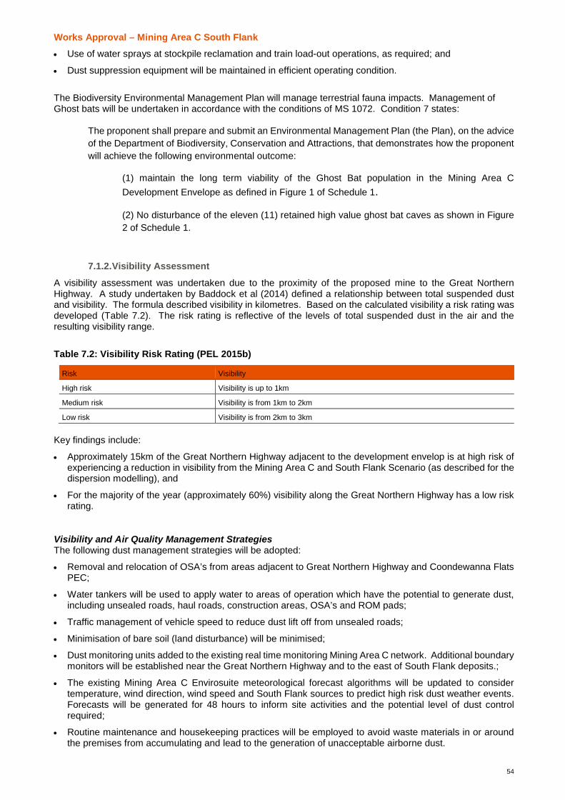
Works Approval – Mining Area C South Flank
54
· Use of water sprays at stockpile reclamation and train load-out operations, as required; and
· Dust suppression equipment will be maintained in efficient operating condition.
The Biodiversity Environmental Management Plan will manage terrestrial fauna impacts. Management ofGhost bats will be undertaken in accordance with the conditions of MS 1072. Condition 7 states:
The proponent shall prepare and submit an Environmental Management Plan (the Plan), on the adviceof the Department of Biodiversity, Conservation and Attractions, that demonstrates how the proponentwill achieve the following environmental outcome:
(1) maintain the long term viability of the Ghost Bat population in the Mining Area CDevelopment Envelope as defined in Figure 1 of Schedule 1.
(2) No disturbance of the eleven (11) retained high value ghost bat caves as shown in Figure2 of Schedule 1.
7.1.2.Visibility Assessment
A visibility assessment was undertaken due to the proximity of the proposed mine to the Great NorthernHighway. A study undertaken by Baddock et al (2014) defined a relationship between total suspended dustand visibility. The formula described visibility in kilometres. Based on the calculated visibility a risk rating wasdeveloped (Table 7.2). The risk rating is reflective of the levels of total suspended dust in the air and theresulting visibility range.
Table 7.2: Visibility Risk Rating (PEL 2015b)
Risk Visibility
High risk Visibility is up to 1km
Medium risk Visibility is from 1km to 2km
Low risk Visibility is from 2km to 3km
Key findings include:
· Approximately 15km of the Great Northern Highway adjacent to the development envelop is at high risk ofexperiencing a reduction in visibility from the Mining Area C and South Flank Scenario (as described for thedispersion modelling), and
· For the majority of the year (approximately 60%) visibility along the Great Northern Highway has a low riskrating.
Visibility and Air Quality Management StrategiesThe following dust management strategies will be adopted:
· Removal and relocation of OSA’s from areas adjacent to Great Northern Highway and Coondewanna FlatsPEC;
· Water tankers will be used to apply water to areas of operation which have the potential to generate dust,including unsealed roads, haul roads, construction areas, OSA’s and ROM pads;
· Traffic management of vehicle speed to reduce dust lift off from unsealed roads;
· Minimisation of bare soil (land disturbance) will be minimised;
· Dust monitoring units added to the existing real time monitoring Mining Area C network. Additional boundarymonitors will be established near the Great Northern Highway and to the east of South Flank deposits.;
· The existing Mining Area C Envirosuite meteorological forecast algorithms will be updated to considertemperature, wind direction, wind speed and South Flank sources to predict high risk dust weather events.Forecasts will be generated for 48 hours to inform site activities and the potential level of dust controlrequired;
· Routine maintenance and housekeeping practices will be employed to avoid waste materials in or aroundthe premises from accumulating and lead to the generation of unacceptable airborne dust.

Works Approval – Mining Area C South Flank
55
· Employees and contractors will be inducted regarding the importance of minimising ambient dust levels and,where possible, measurable dust minimisation targets will be set.
7.1.3.Treated Waste Water
The following management measures will be considered proposed oily water separators are considered torequire specific management measures:
· Site hydrocarbon management will continue to be in accordance with the relevant Dangerous GoodsLicence(s) and the proposed change will not alter the site risk profile;
· Treated water will be released manually to the turkeys nest for dust suppression once monitoring confirmsthe TRH concentration is less than 15mg/L;
· Routine maintenance and housekeeping practices will be employed to maintain capacities of the sumps andwaste oil tanks; and
· An approved contractor will be used for the removal of waste oil in accordance with the EnvironmentalProtection (Controlled Waste) Regulations 2004.
7.1.1.Surface Water
Mining Area C – South Flank does not directly affect any major watercourses or waterbodies. Potential impactson hydrology include localised impacts on surface water resources by changing local surface water patternsthrough construction of open pits and infrastructure or by affecting surface water quality as a result of erosionfrom disturbed areas. Stormwater runoff may collect sediment from cleared areas and result in smothering ofnearby vegetation, impacting growth and survival. Rainfall events at the Premises are likely to be of shortduration and high intensity, and large volume events can be experienced.
The drainage design will ensure that uncontaminated surface water runoff from the surrounding landforms willbe diverted away from infrastructure PC1, PC2, OHP3 and material stockpiles areas. Sedimentation ponds willbe constructed to capture any contaminants collected in surface water run-off from the PC1, PC2, OHP3, andstockyard areas. The sedimentation ponds are designed to prevent stormwater with high sediment loadingdischarging directly to the natural drainage lines.
Surface water managements strategies include:
· Routine maintenance and housekeeping practices will be employed to maintain capacities of thesedimentation ponds.
7.1.2.Atmospheric Gases
Greenhouse gas emissions resulting from Mining Area C and South Flank will be generated through thecombustion of hydrocarbons, clearing of native vegetation, the use of explosives during blasting operationsand the use of electricity. The maximum annual emission of greenhouse gases for the South Flank life of themine is predicted to be equivalent to 909 kilotonnes of carbon dioxide (CO2-e). This corresponds to 0.22% ofAustralia’s and 1.09% of Western Australia’s financial year 2014 greenhouse inventory (Department of theEnvironment and Energy, 2016). The average CO2-e emissions over the life of the mine is predicted to be 385kilotonnes of CO2-e per annum (or 0.46% of Western Australia’s emissions on average).
Management Strategies
Management strategies to minimise greenhouse gas emissions will be focused on:
· Using efficient plant equipment and conducting regular maintenance.
· Tracking of greenhouse gas emissions through site based monitoring programmes.
Greenhouse gas emissions will be monitored and reported on an annual basis as required by NationalGreenhouse and Energy Reporting Act 2007.and MS1072. Condition 8 of MS1072 states:
8-1 The proponent shall publically report the greenhouse gas emissions from the proposal on an annualbasis, in a manner approved by the CEO.

Works Approval – Mining Area C South Flank
56
7.1.3.Amenity
NoiseIncreases in noise and vibration has the potential to impact environmental and social values in the Mining AreaC prescribed premise and surrounds (e.g. residential areas, other land users, fauna and caves).The main sources of noise are expected to be associated with:
· mobile plant, such as excavators, graders, haul trucks and drill rigs;
· fixed plant, such as conveyors, ore processing facilities and the rail loader; and
· blasting noise.
The noise impact assessment undertaken for the Mining Area C (SVT, 2014) predicted that the noise levelswithout mitigation at the Mulla Mulla camp met the assigned levels and predicted that noise levels withoutmitigation at the Packsaddle camp were slightly above (~0.8 dB) assigned levels. The noise modelling wasundertaken with worst-case assumptions, that is with all equipment functioning, equipment located at surfacelevel and located nearest the receptors and during worst case meteorological conditions.
Further noise modelling on a number of scenarios for Mining Area C and South Flank was commissioned. Thescenarios included prediction of noise impacts from the South Flank development in isolation with maximumfleet configuration, South Flank with maximum activities closest to the sensitive receptors and the cumulativescenario of South Flank and Mining Area C.
In line with meteorological guidance, modelling assumed worst-case meteorological conditions. Worst-casemining assumptions were also made, including:
· All mining fleet and fixed plant is operating at once;
· All mining fleet is located at the surface (i.e. noise from equipment is not shielded by pits); and
· Mining fleet is located either nearest to the receptor or represents maximum fleet numbers.
For the South flank ore body development the assigned noise levels were met at the PacksaddleAccommodation Village. The noise model predicted that the noise levels may be above the assigned levels atthe Mulla Mulla Accommodation Village by as much as 4.3 dB(A) when the mining fleet is located closest tothe camp. However, given that the modelling undertaken applying a conservative approach (e.g. assumedworst-case mining conditions). There is a low probability that the assigned level will be exceeded during normaloperations.
The predicted impact for the Proposed Mining Area C Development Envelope shows that the existing MiningArea C equipment operating in the western deposits dominates impacts to the Packsaddle AccommodationVillage.
The indoor noise levels were found to be well below the criterion outlined in AS2107.
Terrestrial Fauna – Noise and VibrationResponses to noise and vibration vary among vertebrate fauna species and individuals according to a numberof factors (Busnel and Fletcher, 1978).. These include
· the characteristics of the noise and its duration;
· life history characteristics of the species;
· habitat type;
· season;
· activity at the time of exposure;
· sex and age of the individual;
· level of previous exposure; and
· whether other stresses are present at the time of exposure.
Potential impacts to Ghost Bats from increased noise are considered to be minor. Noise modelling wasundertaken to determine potential noise levels at the entrances to known caves inhabited by Ghost Bats (SVT2016). All levels were predicted to be below 70 dB, with the highest levels ranging between 65 dB and 69.1 dBat three caves. A study undertaken by Bullen and Creese (2014) suggested that sound levels up to 70 dB are

Works Approval – Mining Area C South Flank
57
unlikely to result in ghost bats leaving their roost; therefore, the impacts of mining-related sound emissions areunlikely to be significant.
A vibration assessment undertaken to predicted likely vibration levels experienced at Ghost Bat caves atvarious distances from a single hole and simultaneous blasting of 10 holes in soft and hard ground types (SVT2016). It is suggested that Ghost Bats will be able to tolerate vibrations of up to 15 mm/s (R. Bullen, pers.comm.), although there has been no specific research undertaken to support this. Further, it would be verydifficult to undertake an assessment of vibration tolerance at South Flank given the low likelihood of locating acontinual population of bats within a cave for study. The vibration assessment indicated for 10 blast holes insoft ground, the received vibration levels are predicted to be 3.4 mm/s at 1 km and 0.4 mm/s at 2 km, whilst forhard ground, the received vibration levels are predicted to be 19.6 mm/s at 1 km and 6.9 mm/s at 2 km. It ispredicted that at 1.1 km a vibration of 15 mm/s will be experienced. One cave (AC13) is located approximately1.1 km from mining operations at Hope Downs 1. This cave continues to be used by ghost bats, and hormoneanalysis shows that pregnant females were using this cave in 2014 (Biologic, in prep). It is considered highlylikely that the soft ground type would be applicable to caves at South Flank, based on current geologicalknowledge. The impacts of vibrations on retained caves are considered to be low.
Noise Management StrategiesManagement strategies to reduce noise levels include:
· use of low noise equipment as per WAIO standard specifications ;
· use of acoustic treatment where necessary;
· installation of fixed barriers (acoustic walls);
· installation of retractable and removable noise curtains;
· consideration for alternative dust seal materials; and
· generators to be located in enclosed areas and at a sufficient distance from personnel areas to minimiseground disturbance.
LightArtificial light could disrupt navigation, cause barriers to movement, impact foraging activity, cause abandoningof roosts and nests and expose nocturnal animals to nocturnal predators (Rich and Longcore, 2006). Additionalimpacts associated with artificial light are considered to be minor and will be managed according to existingmanagement strategies.
7.2. Category 73 Bulk Fuel Storage
7.2.1.Diesel facilities
Potential leaks and spills of diesel from the storage facilities have the potential to contaminate soil and land.The proposed management strategies include:
· The prevention of spills through the implementation of engineering and administrative controls (Table 2.3);.
· Facilities will be constructed in accordance with Australian Standard 1940-2004 The storage and handlingof flammable and combustible liquids;
· Stored and handled in accordance with the requirements of the Dangerous Goods Safety Act 2004;Dangerous Goods Safety (Storage and Handling of non-explosives) Regulations 2007; and AustralianStandard 1940-2004;
· Preventive maintenance will aim to limit the potential for equipment failure leading to environmentalcontamination;
· Spill kits will be provided and maintain at refuelling points and fuel storage facilities;
· Hydrocarbon contaminated soil will be managed and disposed of in accordance with the Conditions ofL7851/2002/6.
7.2.2.Treated Waste Water
Treated waste water management is outlined in section 7.1.3.

Works Approval – Mining Area C South Flank
58
Works Approval – Mining Area C South Flank
59
8. Abbreviations
Term Meaning
AH Act Aboriginal Heritage Act 1972 (WA)
Air NEPM Ambient Air Quality National Environment Protection Measure
AMD acid and metalliferous drainage
ARI average recurrence interval
BHP Billiton Iron Ore One of the BHP Billiton businesses
BOC Bulk Ore Conditioning
BIF banded iron formation
CPWRMP Central Pilbara Water Resource Management Plan
EP Act Environmental Protection Act 1986 (WA)
EPBC Act Environment Protection and Biodiversity Conservation Act 1999 (Cth)
kL Kilolitres
kL/d Kilolitres per day
km kilometre
km2 square kilometre
LA10 is the noise level just exceeded for 10% of the measurement period, A-weighted and calculated byStatistical Analysis
m metre
mbgl metre below ground level
MEM Mobile equipment maintenance
mm millimetres
mm/s millimetres per second
μm micrometre
mg/L milligram per litre
MS Ministerial Statement
OHP Ore Handling Plant
OLC Overland conveyor
OSA overburden storage area
PC Primary Crushing station
PEAHR Project Environment and Aboriginal Heritage Review
PEC Priority Ecological Community
PM10 PM10 refers to the total of suspended particulate matter less than 10 μm in aerodynamic diameter. Particlesin this size range can enter bronchial and pulmonary regions of the respiratory tract and can impact humanhealth. Particles in this size range can remain suspended for many days in the atmosphere.
RIWI Act Rights in Water and Irrigation Act 1914 (WA)
SMU’s soil management units
SRE Short-range endemic
TLO Train Load Out
TSP Total suspended particulates. TSP refers to the total amount of the particulate matter suspended in air,regardless of size.
TRH Total recoverable hydrocarbons
Visibility relates to the reduction in visual distance due to suspended particle light scattering
WAIO Western Australia Iron Ore – represents the same entitiy as BHP Billiton Iron Ore
WC Act Wildlife Conservation Act 1950 (WA)
Works Approval – Mining Area C South Flank
60
9. ReferencesANZECC (1997) Australian and New Zealand Environment and Conservation Council Australian Guidelinesfor Australian Guidelines for Sewage Systems – Effluent Management.
ARMCANZ, ANZECC and NHMRC (2000) Guidelines for Sewage Treatment Systems - Use of ReclaimedWater.
Australian and New Zealand Environment Conservation Council and Agriculture and Resource ManagementCouncil of Australia and New Zealand (ANZECC/ARMCANZ) (2000), Australian Water Guidelines for Freshand Marine Waters and its updates
Australian and New Zealand Minerals and Energy Council and Minerals Council of Australia (ANZMEC/MCA)(2000) Strategic Framework for Mine Closure, Australian and New Zealand Minerals and Energy Council andMinerals Council of Australia, National Library of Australian Catalogue Data
AQ2 (2016) Coondewanna Flats Eco-hydrology Review and Conceptual Model. Unpublished report for BHPBilliton Iron Ore.
Baddock, M., Strong, C., Leys, J., & Heidenreich, S. (2014). A Visibility and total suspended dust relationship.Atmoshpheric Environment, 329 - 336.
Beard J. (1975). Vegetation survey of Western Australia: Pilbara, map and explanatory memoir 1:1,000,000series, University of Western Australia Press, Perth, Western Australia.
Bennelongia (2016) Mining Area C – South Flank: Troglofauna Assessment. Prepared for BHP Billiton IronOre Pty Ltd.
Bettenay, E., Churchward, H.M. and McArthur, W.M. (1967) Atlas of Australian Soils, Sheet 6, Meekatharra-Hamersley Range area, CSIRO
BHP Billiton (2016a). Code of Business Conduct. Available at:http://www.bhpbilliton.com/aboutus/ourcompany/codeofbusconduct.
BHP Billiton (2016b). Our Requirements Community. Available at:http://www.bhpbilliton.com/~/media/bhp/documents/aboutus/ourcompany/governance/160404_gld_community.pdf?la=en.
BHP Billiton (2016c). Our Requirements Environment and Climate Change. Available at:http://www.bhpbilliton.com/~/media/bhp/documents/aboutus/ourcompany/governance/160411_gld_environmentclimatechange.pdf?la=en.
BHP Billiton Iron Ore (2016). Hydrological Impact Assessment and Water Management Summary. BHP BillitonIron Ore Pty Ltd. Perth, Western Australia.
BHP Billiton Iron Ore (2016b). South Flank Preliminary AMD Risk Assessment. BHP Billiton Iron Ore Pty Ltd.Perth, Western Australia.
Biologic Environmental Survey (Biologic) (2011). Southern Flank Vertebrate Fauna Survey. Report for BHPBilliton Pty Ltd.
Biologic Environmental Survey (Biologic) (2016). South Flank Baseline and Targeted SRE Fauna Survey.Report for BHP Billiton Iron Ore, Perth, Western Australia.
Biologic Environmental Survey (Biologic) (2016). South Flank Targeted Fauna Survey. Report for BHP BillitonIron Ore, Perth, Western Australia.
Biologic Environmental Survey (Biologic) (2017). Mining Area C and Southern Flank Desktop Review ofVertebrate Fauna. Report for BHP Billiton Iron Ore, Perth, Western Australia.
BoM (Bureau of Meteorology) (2017a) Climate statistics for Australian locations – Newman Aero.
Works Approval – Mining Area C South Flank
61
Website: http://www.bom.gov.au/climate/averages/tables/cw_007176_All.shtml Accessed: 20 March 2017.
BoM (Bureau of Meteorology) (2017b) Climate statistics for Australian locations – Wittenoom.Website: http://www.bom.gov.au/climate/averages/tables/cw_005026_All.shtml Accessed: 20 March 2017.
Bullen, R. and Creese, S. (2014). A note on the impact on Pilbara leaf-nosed and ghost bat activity from cavesound and vibration levels during drilling operations. The Western Australian Naturalist 29: 145-154.
Busnel, R.G. and Fletcher, J.L. (Eds.) (1978). Effects of Noise on Wildlife. Academic Press, New York.
Bulter R. (2009). Vulnerability of plant functional types to dust deposition in the Pilbara, NW Australia.Unpublished report for the University of Western Australia.
Crowe, M. (2012). Guidelines for Geological Interpretation in the Hamersley Province. Unpublished internaldocument for BHP Billiton Iron Ore
Department of Biodiversity, Conservation and Attractions (DBCA) (2017) PRIORITY ECOLOGICALCOMMUNITIES FOR WESTERN AUSTRALIA VERSION 27 Species and Communities Branch, Departmentof Biodiversity, Conservation and Attractions 30 June 2017
Department of Environment Regulation (2017) Guidance Statement: Risk Assessments. Government ofWestern Australia
Department of Water (2008) Water Quality Protection Note 22 Irrigation with nutrient-rich wastewater.Government of Western Australia
Grierson, P. (2015). Dust suppression and likelihood of adverse impact on Acacia sp. East Fortescue atOrebody 31. Report for BHP Billiton Iron Ore.
Onshore Environmental (2014) Consolidation of Regional Vegetation Mapping BHP Billiton Iron Ore PilbaraTenure. Unpublished Report for BHP Billiton Iron Ore.
Onshore Environmental (2015). Mining Area C Flora and Vegetation Environmental Impact Assessment.Report for BHP Billiton Iron Ore.
Onshore Environmental (2017). Mining Area C Southern Flank. Flora and Vegetation Impact Assessment.Report prepared for BHP Billiton Iron Ore.
Pacific Environment Limited (PEL) (2015a). Air Quality Assessment for Mining Area C. Prepared for BHPBilliton Iron Ore Pty Ltd.
PEL (2015b). Pilbara Strategic Environmental Assessment – Cumulative Air Quality Assessment. ReportNumber 8299. Prepared for BHP Billiton Iron Ore Pty Ltd.
PEL (2016). Updated Air Quality Modelling for South Flank Proposal. Prepared for BHP Billiton Iron Ore PtyLtd.
Shepherd D.P., Beeston G.R. and Hopkins A.J.M. (2002). Native vegetation in Western Australia – extent, typeand status, Resource Management Technical Report 249. Western Australian Department of Agriculture, Perth,Western Australia.
Rich, C. and Longcore, T (eds) (2006). Ecological Consequences of Artificial Night Lighting. Island Press,Washington.
SVT (2014). Environmental Noise Assessment: Mining Area C. Unpublished report prepared for BHP BillitonIron Ore Pty Ltd. Perth, Western Australia.
Works Approval – Mining Area C South Flank
62
SVT (2016). South Flank Environmental Noise Assessment. Report prepared for BHP Billiton Iron Ore. Perth,Western Australia.
Tille P. (2006). Soil-landscapes of Western Australia’s rangelands and arid interior, resource managementtechnical report 313. Report prepared by the Western Australian Department of Agriculture and Food, Perth,Western Australia.
Turner G.F (2013). Vulnerability of Vegetation to Mining Dust at the Jack Hills, Western Australia. Unpublishedreport for the University of Western Australia.
URS (2014). Coondewanna Flats Phase III Water Assessment. Report prepared for BHP Billiton Iron Ore.
van Vreeswyk, A.M.E., Payne, A.L., Leighton, K.A. and Hennig, P. (2004) An Inventory and Condition Surveyof the Pilbara Region, Western Australia. Technical Bulletin No. 92, Department of Agriculture, Perth.
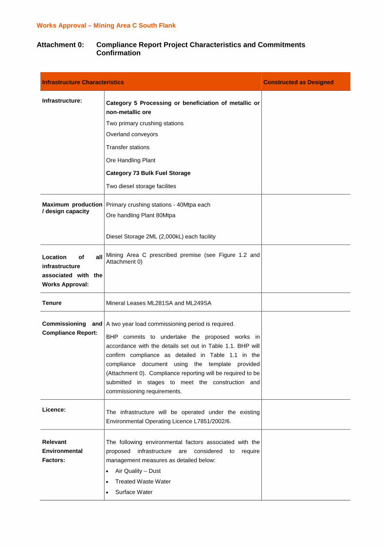
Works Approval – Mining Area C South Flank
Attachment 0: Compliance Report Project Characteristics and CommitmentsConfirmation
Infrastructure Characteristics Constructed as Designed
Infrastructure: Category 5 Processing or beneficiation of metallic ornon-metallic ore
Two primary crushing stations
Overland conveyors
Transfer stations
Ore Handling Plant
Category 73 Bulk Fuel Storage
Two diesel storage facilites
Maximum production/ design capacity
Primary crushing stations - 40Mtpa each
Ore handling Plant 80Mtpa
Diesel Storage 2ML (2,000kL) each facility
Location of allinfrastructureassociated with theWorks Approval:
Mining Area C prescribed premise (see Figure 1.2 andAttachment 0)
Tenure Mineral Leases ML281SA and ML249SA
Commissioning andCompliance Report:
A two year load commissioning period is required.
BHP commits to undertake the proposed works inaccordance with the details set out in Table 1.1. BHP willconfirm compliance as detailed in Table 1.1 in thecompliance document using the template provided(Attachment 0). Compliance reporting will be required to besubmitted in stages to meet the construction andcommissioning requirements.
Licence: The infrastructure will be operated under the existingEnvironmental Operating Licence L7851/2002/6.
RelevantEnvironmentalFactors:
The following environmental factors associated with theproposed infrastructure are considered to requiremanagement measures as detailed below:
· Air Quality – Dust
· Treated Waste Water
· Surface Water
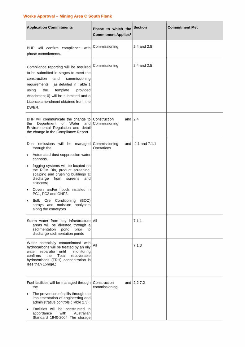
Works Approval – Mining Area C South Flank
Application Commitments Phase to which theCommitment Applies1
Section Commitment Met
BHP will confirm compliance withphase commitments.
Commissioning 2.4 and 2.5
Compliance reporting will be requiredto be submitted in stages to meet theconstruction and commissioningrequirements. (as detailed in Table 1using the template providedAttachment 0) will be submitted and aLicence amendment obtained from, theDWER.
Commissioning 2.4 and 2.5
BHP will communicate the change tothe Department of Water andEnvironmental Regulation and detailthe change in the Compliance Report.
Construction andCommissioning
2.4
Dust emissions will be managedthrough the
· Automated dust suppression watercannons,
· fogging systems will be located onthe ROM Bin, product screening,scalping and crushing buildings atdischarge from screens andcrushers;
· Covers and/or hoods installed inPC1, PC2 and OHP3;
· Bulk Ore Conditioning (BOC)sprays and moisture analysersalong the conveyors
Commissioning andOperations
2.1 and 7.1.1
Storm water from key infrastructureareas will be diverted through asedimentation pond prior todischarge sedimentation ponds
All 7.1.1
Water potentially contaminated withhydrocarbons will be treated by an oilywater separator until monitoringconfirms the Total recoverablehydrocarbons (TRH) concentration isless than 15mg/L;
All 7.1.3
Fuel facilities will be managed throughthe
· The prevention of spills through theimplementation of engineering andadministrative controls (Table 2.3);
· Facilities will be constructed inaccordance with AustralianStandard 1940-2004 The storage
Construction andcommissioning
2.2 7.2

Works Approval – Mining Area C South Flank
and handling of flammable andcombustible liquids;
· Stored and handled in accordancewith the requirements of theDangerous Goods Safety Act 2004;Dangerous Goods Safety (Storageand Handling of non-explosives)Regulations 2007; and AustralianStandard 1940-2004;
Spill kits will be provided and maintainat refueling points and fuel storagefacilities
1 Please note that these commitments only apply to the Pre-construction, Construction and Commissioning phases ofthe project. Commitments related to the Operation and Decommissioning of the infrastructure will be detailed insubsequent license application(s) to the Department of Environment Regulation (DWER)