Working with the BCC 3D Image Shatter...
14
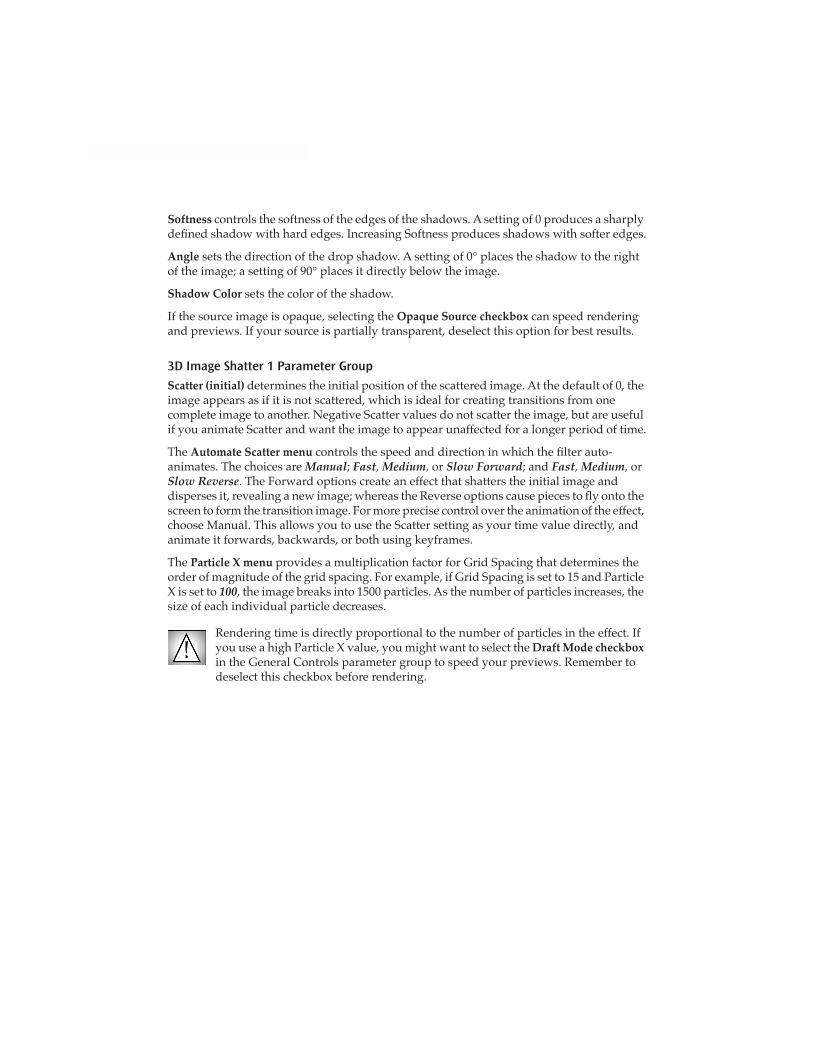
Working with the BCC 3D Image Shatter Filter 3D Image Shatter shatters the image in 3D space and disperses the image fragments. The lter provides a variety of explosion, velocity, and gravity parameters to control particle movement. In addition, 3D Image Shatter has a number of parameters that allow you to control the particle size and shape, rotation, opacity, lighting, and explosion style. This lter is auto-animated by default, but you can manually animate it for more precise control over the movement and dispersion of the particles. 3D Image Shatter effect Time 00:00:00:00 Time 00:00:00:15 Time 00:00:01:00 The Image Shatter lter includes extensive parameters for you to customize. You may need to scroll to see them all. The illustration at right does not show all the parameters. The BCC 3D Image Shatter lter can also be used as a transition. To apply it as a transition, use the BCC TR 3D Image Shatter in the BCC Transitions category or apply the lter to two layers. General Controls Parameter Group At times, you may want to view your clip without the effect that youve applied. The Bypass Effect checkbox lets you view the source footage without the effect. When the Bypass Effect checkbox is
Transcript of Working with the BCC 3D Image Shatter...
Working with the BCC 3D Image Shatter Filter
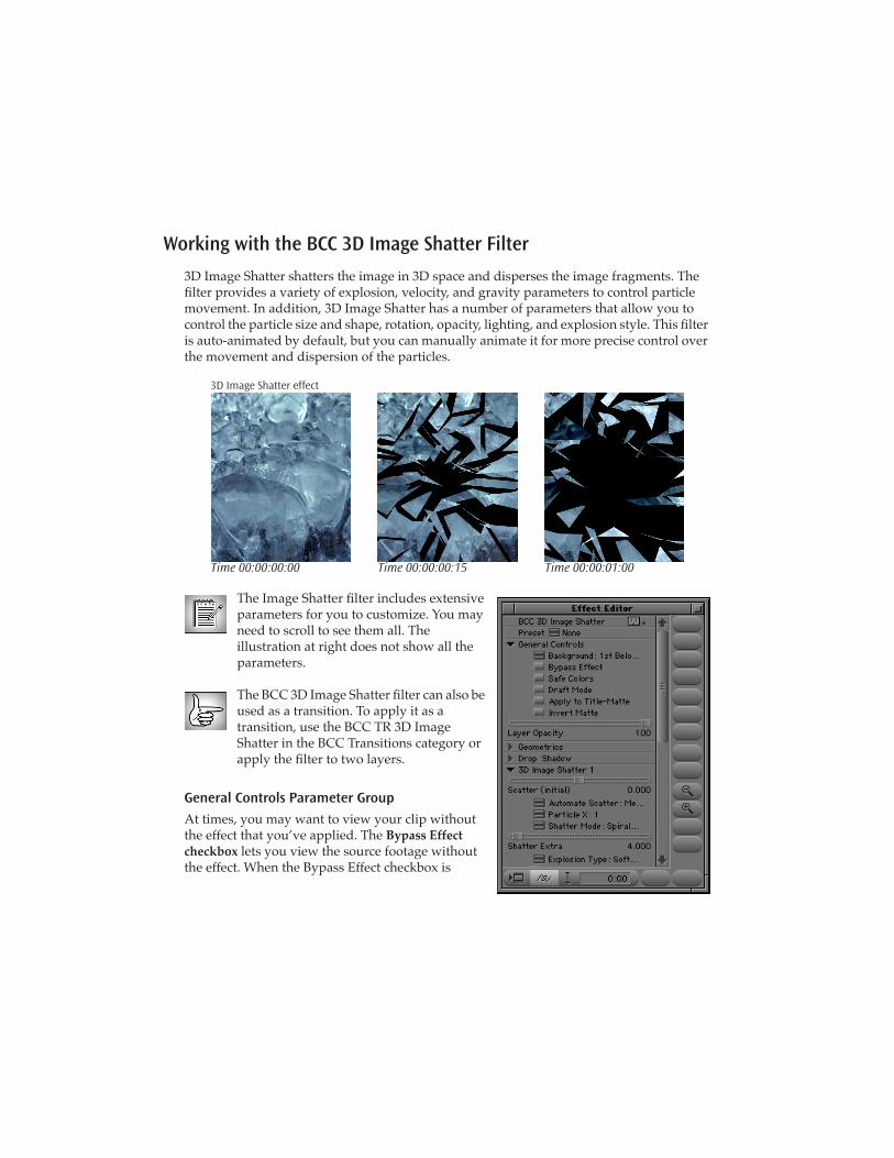
3D Image Shatter shatters the image in 3D space and disperses the image fragments. The Þlter provides a variety of explosion, velocity, and gravity parameters to control particle movement. In addition, 3D Image Shatter has a number of parameters that allow you to control the particle size and shape, rotation, opacity, lighting, and explosion style. This Þlter is auto-animated by default, but you can manually animate it for more precise control over the movement and dispersion of the particles.
3D Image Shatter effect
Time 00:00:00:00 Time 00:00:00:15 Time 00:00:01:00
The Image Shatter Þlter includes extensive parameters for you to customize. You may need to scroll to see them all. The illustration at right does not show all the parameters.
The BCC 3D Image Shatter Þlter can also be used as a transition. To apply it as a transition, use the BCC TR 3D Image Shatter in the BCC Transitions category or apply the Þlter to two layers.
General Controls Parameter Group
At times, you may want to view your clip without the effect that you�ve applied. The
Bypass Effect checkbox
lets you view the source footage without the effect. When the Bypass Effect checkbox is
selected, it turns pink. When you applied a BCC effect to an Avid title or matte, enabling the
Bypass Effect checkbox
does not display the original title unÞltered, but rather displays the nested Graphic Fill of the matte key.
Bypass Effect is a parameter change; selecting the Bypass Effect checkbox will unrender a rendered effect. To bypass a rendered effect without unrendering, step into the effect in the Avid timeline to see the unaffected video.
Selecting the
Safe Colors checkbox
enables an NTSC/PAL color-safe Þlter that allows only colors that are safe for broadcast. BCC allows RGB values across the full 0-255 range. When this checkbox is selected, the RGB values are limited to the NTSC/PAL safe range of 16-235.
The
Draft Mode checkbox
allows you to preview your effect in a Draft Mode to speed previews. This is especially useful for effects with multiple track inputs. Deselect this option before rendering your effect.
The
Apply to Title-Matte checkbox
allows you to apply BCC Þlters to titles created in Avid�s Title tool. To apply an effect to a title, drag the effect onto the title (you do not have to Option-drag) and select the
Apply to Title-Matte checkbox
.
The
Invert Matte checkbox
allows you to invert any matte created by your effect. This is useful when you work with imported images.
The
Layer Opacity
slider sets the opacity of the Þlter layer, which allows you to fade effects. When
Apply to Title-Matte checkbox
is selected, Layer Opacity affects the graphic Þll layer, which allows you to fade titles.
The
Field Render menu
sets the rendering optimization for BCC. For most Þlters, you can use the default of
Speed Optimized
. For effects that include edging or DVE moves, you may want to use
Quality Optimized
. Quality Optimized takes more time to render, but will generally correct any problems with jitter or rough edges on effects.
Geometrics Parameter Group
The controls in the Geometrics parameter group allow you to add basic DVE moves to any Þlter.
The Geometrics parameter group includes the following controls.
Selecting the
Enable Geometrics checkbox
allows you to use the parameters to reposition a track. When this checkbox is deselected, the other parameters have no affect.
Position
X
and
Position Y
adjust the horizontal and vertical location of the track.
Scale X
and
Scale Y
change the size of the image along the X and Y axis, respectively. These parameters scale as percentages of the image�s original width and height. Thus, a Scale X value of 200 produces an image twice as wide as the original. Select the
Lock Scale checkbox
to keep the Scale X and Y values in proportion.
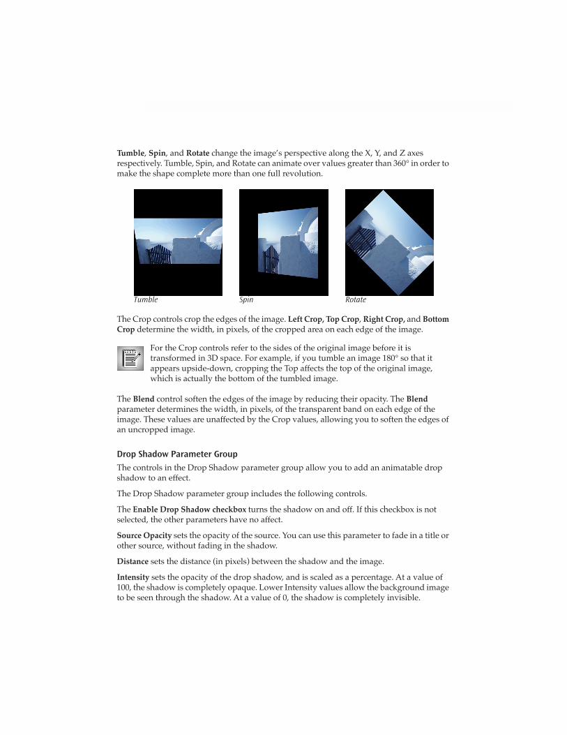
Tumble
,
Spin
, and
Rotate
change the image�s perspective along the X, Y, and Z axes respectively. Tumble, Spin, and Rotate can animate over values greater than 360° in order to make the shape complete more than one full revolution.
Tumble Spin Rotate
The Crop controls crop the edges of the image.
Left Crop, Top Crop
,
Right
Crop,
and
Bottom Crop
determine the width, in pixels, of the cropped area on each edge of the image.
For the Crop controls refer to the sides of the original image before it is transformed in 3D space. For example, if you tumble an image 180° so that it appears upside-down, cropping the Top affects the top of the original image, which is actually the bottom of the tumbled image.
The
Blend
control soften the edges of the image by reducing their opacity. The
Blend
parameter
determines the width, in pixels, of the transparent band on each edge of the image. These values are unaffected by the Crop values, allowing you to soften the edges of an uncropped image.
Drop Shadow Parameter Group
The controls in the Drop Shadow parameter group allow you to add an animatable drop shadow to an effect.
The Drop Shadow parameter group includes the following controls.
The
Enable Drop Shadow checkbox
turns the shadow on and off. If this checkbox is not selected, the other parameters have no affect.
Source Opacity
sets the opacity of the source. You can use this parameter to fade in a title or other source, without fading in the shadow.
Distance
sets the distance (in pixels) between the shadow and the image.
Intensity
sets the opacity of the drop shadow, and is scaled as a percentage. At a value of 100, the shadow is completely opaque. Lower Intensity values allow the background image to be seen through the shadow. At a value of 0, the shadow is completely invisible.
Softness
controls the softness of the edges of the shadows. A setting of 0 produces a sharply deÞned shadow with hard edges. Increasing Softness produces shadows with softer edges.
Angle
sets the direction of the drop shadow. A setting of 0° places the shadow to the right of the image; a setting of 90° places it directly below the image.
Shadow Color
sets the color of the shadow.
If the source image is opaque, selecting the
Opaque Source
checkbox
can speed rendering and previews. If your source is partially transparent, deselect this option for best results.
3D Image Shatter 1 Parameter Group
Scatter (initial)
determines the initial position of the scattered image. At the default of 0, the image appears as if it is not scattered, which is ideal for creating transitions from one complete image to another. Negative Scatter values do not scatter the image, but are useful if you animate Scatter and want the image to appear unaffected for a longer period of time.
The
Automate Scatter
menu
controls the speed and direction in which the Þlter auto-animates. The choices are
Manual
;
Fast
,
Medium
,
or
Slow Forward
; and
Fast
,
Medium
,
or
Slow Reverse
. The Forward options create an effect that shatters the initial image and disperses it, revealing a new image; whereas the Reverse options cause pieces to ßy onto the screen to form the transition image. For more precise control over the animation of the effect, choose Manual. This allows you to use the Scatter setting as your time value directly, and animate it forwards, backwards, or both using keyframes.
The
Particle X menu
provides
a multiplication factor for Grid Spacing that determines the order of magnitude of the grid spacing. For example, if Grid Spacing is set to 15 and Particle X is set to
100
, the image breaks into 1500 particles. As the number of particles increases, the size of each individual particle decreases.
Rendering time is directly proportional to the number of particles in the effect. If you use a high Particle X value, you might want to select the
Draft Mode checkbox
in the General Controls parameter group to speed your previews. Remember to deselect this checkbox before rendering.
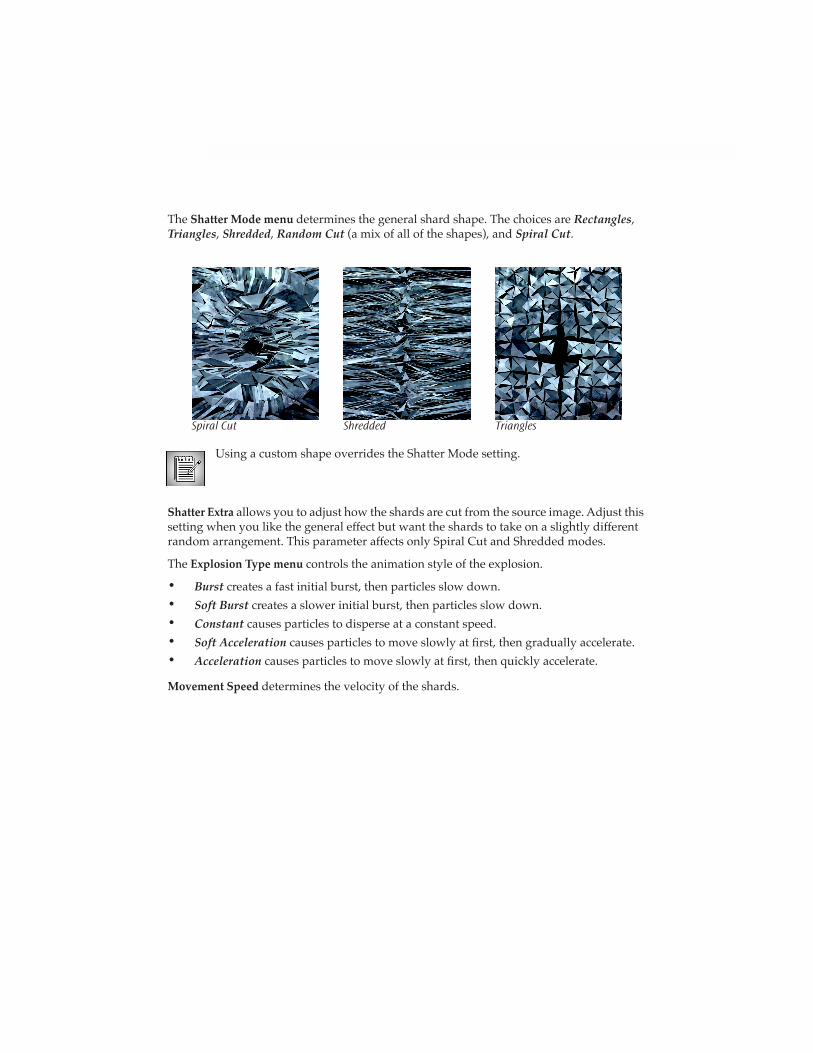
The
Shatter Mode menu
determines the general shard shape. The choices are
Rectangles
,
Triangles
,
Shredded
,
Random Cut
(a mix of all of the shapes), and
Spiral Cut
.
Spiral Cut Shredded Triangles
Using a custom shape overrides the Shatter Mode setting.
Shatter Extra
allows you to adjust how the shards are cut from the source image. Adjust this setting when you like the general effect but want the shards to take on a slightly different random arrangement. This parameter affects only Spiral Cut and Shredded modes.
The
Explosion Type menu
controls the animation style of the explosion.
•
Burst
creates a fast initial burst, then particles slow down.
•
Soft Burst
creates a slower initial burst, then particles slow down.
•
Constant
causes particles to disperse at a constant speed.
•
Soft Acceleration
causes particles to move slowly at Þrst, then gradually accelerate.
•
Acceleration
causes particles to move slowly at Þrst, then quickly accelerate.
Movement Speed
determines the velocity of the shards.
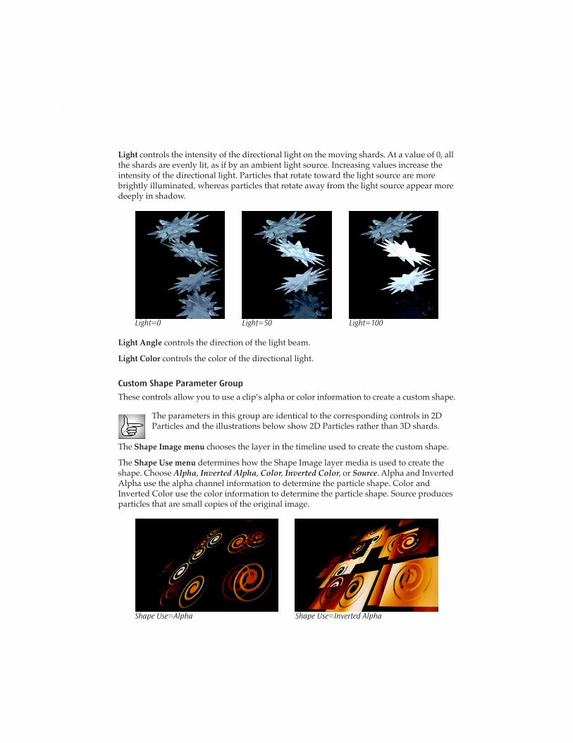
Light
controls the intensity of the directional light on the moving shards. At a value of 0, all the shards are evenly lit, as if by an ambient light source. Increasing values increase the intensity of the directional light. Particles that rotate toward the light source are more brightly illuminated, whereas particles that rotate away from the light source appear more deeply in shadow.
Light=0 Light=50 Light=100
Light Angle
controls the direction of the light beam.
Light Color
controls the color of the directional light.
Custom Shape Parameter Group
These controls allow you to use a clip�s alpha or color information to create a custom shape.
The parameters in this group are identical to the corresponding controls in 2D Particles and the illustrations below show 2D Particles rather than 3D shards.
The
Shape Image menu
chooses the layer in the timeline used to create the custom shape.
The
Shape Use
menu
determines how the Shape Image layer media is used to create the shape. Choose
Alpha
,
Inverted Alpha
,
Color
,
Inverted Color
, or
Source
. Alpha and Inverted Alpha use the alpha channel information to determine the particle shape. Color and Inverted Color use the color information to determine the particle shape. Source produces particles that are small copies of the original image.
Shape Use=Alpha Shape Use=Inverted Alpha

Shape Size
determines how the Shape Image layer media is scaled in creating the particles.
Larger
means that the custom shape size is greater than or equal to the original particle size,
Smaller
means that it is less than or equal to the original particle size, and
Conform to Particle
means it is scaled to the size of the original Shape Image layer media from which the particles are made.
Shape Transformation
is a manually animatable choking control that transforms each particle into a rectangle. At a Shape Transformation value of 0, the particles are unaffected and conform to the custom shape. At a value of 100, the particles are completely rectangular. This parameter is useful for creating smooth transitions in which the original image splits into rectangles which then transform into the custom shape. In the examples below, the custom shape is a circle, and the image is unscattered.
Shape Transformation=0 Shape Transformation=10 Shape Transformation=25
The
Shape Type menu
determines how the animation of the Shape Image layer affects the particle shape.
•
When
Animate Shape
is chosen, the custom shape animates along with the source Shape Image layer.
•
Random Frames
chooses the Þrst few frames of the custom shape image and randomly distributes those shapes among the particles. When Random Frames is selected,
Shape Frame Count
determines the number of frames selected from the Shape Image layer.
Shape Random Seed
sets which value is input to the random number generator used by the Þlter to determine which Shape Image layer frame is used for each output frame.
Adjust
Resample Quality
to maximize the quality and/or minimize the render time and memory requirement of custom shape effects. Resample Quality places a limit on how large the particles become before losing quality. A setting of 10 means particles can become as large as the original custom shape image, and 5 means they can become half as large.
If your particles are relatively small, you can use a fairly low Resample Quality value without a noticeable loss of image quality while signiÞcantly decreasing rendering time.
If you select the
Optimize Resample checkbox
, the Þlter automatically performs Resample Quality adjustments for you.
Move Parameter Group
These parameters adjust the particles� movement.
The
Velocity Type menu
controls the pattern of movement the particles follow.
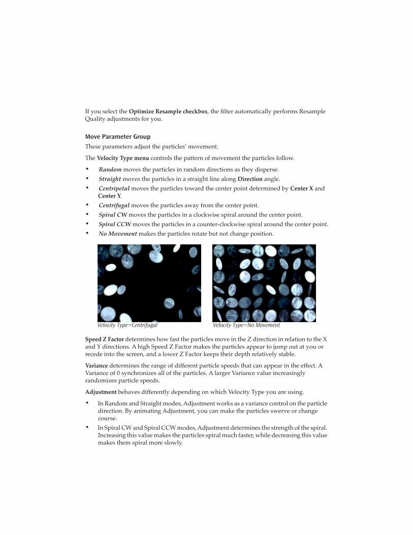
•
Random
moves the particles in random directions as they disperse.
•
Straight
moves the particles in a straight line along
Direction
angle.
•
Centripetal
moves the particles toward the center point determined by
Center X
and
Center Y
.
•
Centrifugal
moves the particles away from the center point.
•
Spiral CW
moves the particles in a clockwise spiral around the center point.
• Spiral CCW moves the particles in a counter-clockwise spiral around the center point.
• No Movement makes the particles rotate but not change position.
Velocity Type=Centrifugal Velocity Type=No Movement
Speed Z Factor determines how fast the particles move in the Z direction in relation to the X and Y directions. A high Speed Z Factor makes the particles appear to jump out at you or recede into the screen, and a lower Z Factor keeps their depth relatively stable.
Variance determines the range of different particle speeds that can appear in the effect. A Variance of 0 synchronizes all of the particles. A larger Variance value increasingly randomizes particle speeds.
Adjustment behaves differently depending on which Velocity Type you are using.
• In Random and Straight modes, Adjustment works as a variance control on the particle direction. By animating Adjustment, you can make the particles swerve or change course.
• In Spiral CW and Spiral CCW modes, Adjustment determines the strength of the spiral. Increasing this value makes the particles spiral much faster, while decreasing this value makes them spiral more slowly.

• In Centripetal and Centrifugal modes, Adjustment has no affect.
Center of Velocity sets the horizontal and vertical coordinates of the center point from, toward, or around which the particles move when Velocity Type is set to Centripetal, Centrifugal, Spiral CW, or Spiral CCW.
Velocity Radius sets the radius of the particle system when Velocity Type is set to Centripetal, Centrifugal, Spiral CW, or Spiral CCW.
Rotate Parameters
The Rotate parameters allow you to precisely control, synchronize, or desynchronize the 3D rotation of the particles. These parameters determine the speed, direction, and chaos in the shatter effect.
The Rotate Mode menu determines whether the particles rotate forwards, backwards, or in both directions. Rotate Mode defaults to Both, but if you want to synchronize the particles, set it to Forward or Backward.
X Rotate Speed, Y Rotate Speed, and Z Rotate Speed determine the speed at which the particles rotate around the X, Y, and Z axes respectively.
Rotate Variance determines the range of different particle rotation speeds that appear in the image. A Rotate Variance of 0 synchronizes the particles, whereas a high Rotate Variance makes some of the particles spin quickly while others rotate more slowly or not at all.
Chaos Wind adds an element of chaos to the particles� movement, blowing the particles about randomly as they move. Increasing Chaos Wind varies particle movement, which can create a more natural effect.
Chaos Wind=0 Chaos Wind=25
Scatter Wipe Parameter Group
Parameters in the Scatter Wipe group shatter images in a wipe-like fashion, and control the rate and direction in which shards break off and disperse. You can wipe the shards in a single direction or use a custom gradient to determine how the image breaks into shards.
In the Scatter Wipe menu, choose between Off, On, Pass Through and Random.
• With Off chosen, no wipe takes place (unless you set up a Custom Gradient).
• With On chosen, the particles wipe across in the pattern designated by the Wipe Custom Gradient (see below).
• Pass Through is similar to On, except that the particles begin at a negative Scatter value rather than a value of 0. Particles come together along the edge of the wipe, then fall apart again as the wipe passes across the screen. This creates an effect which looks like a line that forms and dissipates the image as the line moves across the screen.
• With Random Wipe chosen, the particles break off randomly across the screen.
The Wipe Custom Gradient menu allows you to select any layer in your timeline to use as the wipe gradient. Regions in the image corresponding to the darkest areas in the gradient break up Þrst, followed by increasingly lighter areas. If None is selected, the wipe moves across the screen in a straight line. The direction of the line is determined by the Wipe Angle setting.
The Invert Gradient checkbox inverts the luma or alpha values in the custom wipe gradient, thereby reversing the scatter wipe pattern.
Wipe Speed adjusts the speed of the wipe by determining the Scatter value at which the whole image is broken in particles. For a faster wipe, decrease Wipe Speed. For a more gradual wipe, increase Wipe Speed.
Regardless of the particles� Speed setting, a low Wipe Speed value wipes the image quickly, and a high Wipe Speed value wipes the image slowly. With high-speed particles and a low-speed wipe, the image unravels slowly, but each particle ßies away from the image extremely quickly. With slow particles and a fast wipe, the image breaks up quickly, but the particles then slowly drift off the screen.
Gravity Parameter Group
The Gravity controls apply a simulated gravitational force to the velocity of the shards.
The Gravity Type menu is similar to Velocity Type except that Gravity is applied as acceleration rather than as direct movement.
• Random applies a random gravitational pull to the particles.
• Straight is the most �natural� type of gravity because it exerts a straight downward pull on the particles. You can pull the gravity in any direction by adjusting the Gravity Angle control, which can be used to simulate wind.

• Centripetal applies gravity that pulls particles away from the point deÞned by the Center of Gravity position controls.
• Centrifugal pulls particles away from the point deÞned by Center of Gravity.
Options Parameter Group
The Options parameters affect particle density, position, size and behavior.
3D Velocity Mode determines which way the particles move in the Z direction. Choose Forward, Backward, or Both.
The rest of the parameters in this group are identical to the corresponding controls in 2D Particles and the illustrations below show 2D Particles rather than 3D shards.
Grid Spacing works in conjunction with Particle X to determine the number of particles created from the image. Higher values make the grid resolution greater, generating a larger number of smaller particles; while lower values generate a smaller number of larger particles. The Grid Spacing value is multiplied by the Particle X value to determine the total number of particles.
Density controls the density of the particles in relation to each other. Low Density values spread the particles farther apart; high values pack the particles more closely together.
Position Variance varies the positions of each particle. Increase this setting to create a more random particle arrangement.
At any Position Variance value greater than 0, the unscattered image has some scattered particles, creating holes in the source image. Animate Position Variance along with Scatter to avoid this problem.
Size adjusts the size of the particles without affecting the grid spacing or the number of particles. At the default setting of 100, the image splits into the number of particles determined by the Particle X and Grid Spacing settings. If you increase Size, each particle maintains its original position in the grid but increases in size, so that the image fragments overlap in the unscattered image. Conversely, if you decrease Size, the unscattered particles maintain their positions but do not Þll the screen.
Size=50 Size=100 Size=125
Size Variance varies the size of the particles by scaling them to 100% of their original size plus the Size Variance value. For example, the default setting of 0 creates particles that are 100% of their original size (that is, the particle size does not change). A Size Variance of 50 produces particles that range up to 150% of their original size, and a value of �50 creates particles that range down to 50% of their original size.
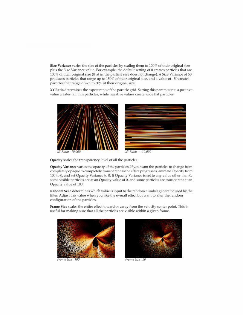
XY Ratio determines the aspect ratio of the particle grid. Setting this parameter to a positive value creates tall thin particles, while negative values create wide ßat particles.
XY Ratio=10,000 XY Ratio= –10,000
Opacity scales the transparency level of all the particles.
Opacity Variance varies the opacity of the particles. If you want the particles to change from completely opaque to completely transparent as the effect progresses, animate Opacity from 100 to 0, and set Opacity Variance to 0. If Opacity Variance is set to any value other than 0, some visible particles are at an Opacity value of 0, and some particles are transparent at an Opacity value of 100.
Random Seed determines which value is input to the random number generator used by the Þlter. Adjust this value when you like the overall effect but want to alter the random conÞguration of the particles.
Frame Size scales the entire effect toward or away from the velocity center point. This is useful for making sure that all the particles are visible within a given frame.
Frame Size=100 Frame Size=50
Parameters such as Size and Position Variance affect the initial (unscattered) image. Parameter Suppression allows you to animate all these parameters at once. To animate from an unscattered image to a scattered image that uses these parameters, set a keyframe with a Parameter Suppression value of 100 at the start of the effect, and animate the value to 0. This suppresses the parameters that affect the unscattered image at the start of the effect.
Mix with Original blends the source and Þltered images. Use this parameter to animate the effect from the unÞltered to the Þltered image without adjusting other settings, or to reduce the affect of the Þlter by mixing it with the source image.