Working With Designs in Memory 6 - VLSI IP · PDF fileHOME CONTENTS INDEX / 6-1 v1999.10...
42
/ 6-1 HOME CONTENTS INDEX v1999.10 Design Compiler User Guide 6 Working With Designs in Memory 6 Design Compiler reads designs into memory from design files. Many designs can be in memory at any time. After a design is read in, you can change it in numerous ways, such as grouping or ungrouping its subdesigns or changing subdesign references. This chapter contains the following sections: • Understanding Design Terminology • Reading Designs • Listing Designs in Memory • Setting the Current Design • Linking Designs • Listing Design Objects • Specifying Design Objects
Transcript of Working With Designs in Memory 6 - VLSI IP · PDF fileHOME CONTENTS INDEX / 6-1 v1999.10...

v1999.10 Design Compiler User Guide
6Working With Designs in Memory 6
Design Compiler reads designs into memory from design files. Manydesigns can be in memory at any time. After a design is read in, youcan change it in numerous ways, such as grouping or ungrouping itssubdesigns or changing subdesign references.
This chapter contains the following sections:
• Understanding Design Terminology
• Reading Designs
• Listing Designs in Memory
• Setting the Current Design
• Linking Designs
• Listing Design Objects
• Specifying Design Objects
/ 6-1HOME CONTENTS INDEX
v1999.10 Design Compiler User Guide
• Creating Designs
• Copying Designs
• Renaming Designs
• Changing the Design Hierarchy
• Editing Designs
• Translating Designs From One Technology to Another
• Removing Designs From Memory
• Saving Designs
• Working With Attributes
Understanding Design Terminology
Different companies might use different terminology for designs andtheir components. This section describes the terminology used bythe Synopsys synthesis tools.
Designs
Designs are circuit descriptions that perform logical functions.Designs are described in various design formats, such as VHDL,Verilog HDL, state machine, and Electronic Data Interchange Format(EDIF).
Logic-level designs are represented as sets of Boolean equations.Gate-level designs, such as netlists, are represented asinterconnected cells.
/ 6-2HOME CONTENTS INDEX

v1999.10 Design Compiler User Guide
Designs can exist and be compiled independently of one another orcan be used as subdesigns in larger designs. Designs are hierarchicalor flat.
Hierarchical Designs
A hierarchical design contains one or more designs as subdesigns.Each subdesign can further contain subdesigns, creating multiplelevels of design hierarchy. Designs that contain subdesigns are calledparent designs.
Figure 6-1 shows the three levels of hierarchy in the TOP design.
Figure 6-1 TOP Design Hierarchy
TOP has three input ports and one output port. The ports of CELL1and CELL2 are also pins of TOP. TOP and CELL1 are parent designs.CELL2 is instantiated twice in CELL1.
Flat Designs
Flat designs contain no subdesigns and have only one structural level.They contain only library cells.
TOP
CELL1
CELL2 CELL2
U1
U1 U2
/ 6-3HOME CONTENTS INDEX

v1999.10 Design Compiler User Guide
Design Objects
A design consists of cells, nets, ports, and pins. It can containsubdesigns and references to subdesigns and library cells.
Synopsys commands, attributes, and constraints are directed towarda design object.
Figure 6-2 shows the design objects in the TOP design example.
Figure 6-2 Design Objects in TOP Design
Current Design
The active design (the design being worked on) is called the currentdesign. Most commands are specific to the current design, that is,they operate within the context of the current design.
Cells, Instances, and References
A unique instance of a design within another design is called ahierarchical cell. A unique instance of a library cell within a design iscalled a leaf cell. The term instance is also used to refer to a cell.
TOP
port1
port2port4
U1/pin1
U1/pin2
U1/pin4
U1
CELL2 CELL2
(also CELL1/port1)
(also CELL1/port4)
CELL1
U1 U2
U1/pin3port3
/ 6-4HOME CONTENTS INDEX

v1999.10 Design Compiler User Guide
Some commands work within the context of a hierarchical instanceof the current design. The current instance defines the active instancefor these instance-specific commands.
Cells are defined by their attributes, such as their functions, wiring(connections), size, and timing.
A design can contain multiple instances of identical subdesigns orlibrary cells. The instantiated subdesign or library cell is called thereference. Each instance points to the same reference but has aunique name to differentiate it from the other instances.
References enable you to optimize every cell (such as a NAND gate)in a single design without affecting cells in other designs. The cellreferences in one design are independent of the same cell referencesin a different design.
Figure 6-3 shows the relationships among designs, cells, andreferences.
Figure 6-3 Cells and Cell References
The EXREF design contains two references: NAND2 andMULTIPLIER. NAND2 is instantiated three times, and MULTIPLIERis instantiated once.
EXREF
NAND2
MULTIPLIER
U1
NAND2
U3
NAND2
U2
U4
References
NAND2
MULTIPLIER
/ 6-5HOME CONTENTS INDEX

v1999.10 Design Compiler User Guide
The names given to the three instances of NAND2 are U1, U2, andU3. The references of NAND2 and MULTIPLIER in the EXREF designare independent of the same references in different designs.
For information about resolving references, see “Linking Designs” onpage 6-13.
Nets
Nets (networks) are the wires that connect ports to pins and pins toeach other. A net is the electrical connection between ports and pinsof a signal (from the first port or pin to the last in the signal).
Ports
Ports are the inputs and outputs of a design. The signal flow of portsis defined as input, output, or inout.
Pins
Pins are the input and output of cells within a design (such as gatesand flip-flops). The ports of a subdesign are pins within the parentdesign.
/ 6-6HOME CONTENTS INDEX

v1999.10 Design Compiler User Guide
Reading Designs
Table 6-1 lists the design file formats supported by Design Compiler.Design Compiler supports input and output of all formats listed in thistable. All formats except .db, EDIF, equation, PLA, and state tablerequire special license keys.
Table 6-1 Supported Design File Formats
Format Description Keyword Extension
.db Synopsys internal database format db .db
EDIF Electronic Design Interchange Format (see theSynopsys EDIF 2 0 0 Interface User Guide)
edif .edif
equation Synopsys equation format equation .eqn
LSI LSI Logic Corporation (NDL) netlist format lsi .NET
Mentor Mentor NETED do Format (output only) mentor .neted
MIF Mentor Intermediate Format (input only) mif .mif
PLA Berkeley (Espresso) PLA format pla .pla
statetable
Synopsys state table format st .st
TDL Tegas Design Language netlist format tdl .tdl
Verilog Verilog Hardware Description Language (seethe HDL Compiler for Verilog ReferenceManual)
verilog .v
VHDL VHSIC Hardware Description Language (seethe VHDL Compiler Reference Manual)
vhdl .vhd
XNF Xilinx netlist format (see the FPGA CompilerUser Guide)
xnf .xnf
/ 6-7HOME CONTENTS INDEX

v1999.10 Design Compiler User Guide
Design Compiler provides two ways to read design files:
• The read_file command
dc_shell> read_file -format keyword design_file
• The analyze and elaborate commands
dc_shell> analyze -format keyword design_filedc_shell> elaborate design_name
Table 6-2 summarizes the differences between using the read_filecommand and using the analyze and elaborate commands toread design files.
A design file exists in your host computer’s file system. When youread a design file into Design Compiler, it is stored in a memory filein the Synopsys internal database (.db) format. The memory file existsonly in the working memory of the Design Compiler program.
Table 6-2 read_file Versus analyze and elaborate Commands
Comparison read_file Command analyze and elaborate Commands
Input formats All formats VHDL, Verilog
When to use Netlists, precompiled designs,and so forth
Synthesizing VHDL or Verilog
Designlibraries
Cannot store analyzed resultsexcept in design library WORK
Can store analyzed results inspecified design libraries (use theanalyze command option -library or -work)
Generics Cannot pass parameters (mustuse directives in HDL)
Allows you to set parameter values onthe elaborate command line
Architecture Cannot specify architecture to beelaborated
Allows you to specify architecture tobe elaborated
/ 6-8HOME CONTENTS INDEX

v1999.10 Design Compiler User Guide
Design Compiler names the memory file path_name / design.db. Thepath_name argument is the directory from which the original file wasread, and the design argument is the name of the design. If you laterread in a design that has the same memory file name, DesignCompiler overwrites the original design. To prevent this, use the -single_file option with the read_file command.
Using a Search Path
You can specify the design file location by using the complete pathor only the file name. If you specify only the file name, Design Compileruses the search path defined in the search_path variable to locatethe design files. Design Compiler looks for the design files startingwith the leftmost directory specified in the search_path variableand uses the first library file it finds. When you specify the path, DesignCompiler does not use the search path.
To see where Design Compiler finds a file when using the searchpath, use the which command. For example, enter
dc_shell> which my_design.db{/usr/designers/example/my_design.db}
Reading .db Files
The version of a .db file is the version of Design Compiler that createdthe file. To read a .db file into Design Compiler, the file must have thesame or earlier version than the version of Design Compiler you arerunning.
/ 6-9HOME CONTENTS INDEX

v1999.10 Design Compiler User Guide
If you attempt to read in a .db file generated by a Design Compilerversion later than the Design Compiler version you are using, an errormessage appears. The error message provides details about theversion mismatch.
Reading HDL Designs
Use the following process to read HDL designs:
1. Analyze the top-level design and all subdesigns in bottom-uporder (to satisfy any dependencies).
2. Elaborate the top-level design and any subdesigns that requireparameters to be assigned or overwritten.
Analyzing Designs
The analyze command
• Reads an HDL source file
• Checks it for errors (without building generic logic for the design)
• Creates HDL library objects in an HDL-independent intermediateformat
• Stores the intermediate files in a location you define
If the analyze command reports errors, fix them in the HDL sourcefile and run analyze again.
/ 6-10HOME CONTENTS INDEX
v1999.10 Design Compiler User Guide
Once a design is analyzed, you must reanalyze the design only whenyou change it. In addition, because Design Compiler and theSynopsys VHDL System Simulator (VSS) use a common analyzer,you do not need to reanalyze VHDL files analyzed during simulation(unless they have changed).
Elaborating Designs
The elaborate command creates a technology-independentdesign from the intermediate files produced during analysis. You canoverride default parameter values during elaboration. Elaborationreplaces the HDL arithmetic operators in the code with DesignWarecomponents and determines the correct bus size.
For more information about the analyze and elaboratecommands, see the HDL Compiler for Verilog Reference Manual orthe VHDL Compiler Reference Manual.
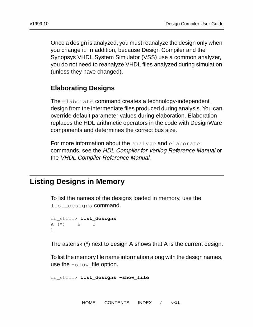
Listing Designs in Memory
To list the names of the designs loaded in memory, use thelist_designs command.
dc_shell> list_designsA (*) B C1
The asterisk (*) next to design A shows that A is the current design.
To list the memory file name information along with the design names,use the -show _file option.
dc_shell> list_designs -show_file
/ 6-11HOME CONTENTS INDEX

v1999.10 Design Compiler User Guide
/user1/designs/design_A/A.dbA (*)
/home/designer/dc/B.dbB C1
The asterisk (*) next to design A shows that A is the design you areworking on. File B.db contains both designs B and C.
To check for duplicate designs loaded in memory, use thelist_duplicate_designs command.
dc_shell> list_duplicate_designsWarning: Multiple designs in memory with the same designname.
Design File Path ------ ---- ---- seq2 A.db /home/designer/dc seq2 B.db /home/designer/dc1
Setting the Current Design
The current_design variable points to the current design and isset in the following ways:
• With the read_file command
When the read_file command successfully completesprocessing, it sets the current design to the design read in.
dc_shell> read_file -format edif MY_DESIGN.edifLoading edif file ’/designs/ex/MY_DESIGN.edif’
/ 6-12HOME CONTENTS INDEX
v1999.10 Design Compiler User Guide
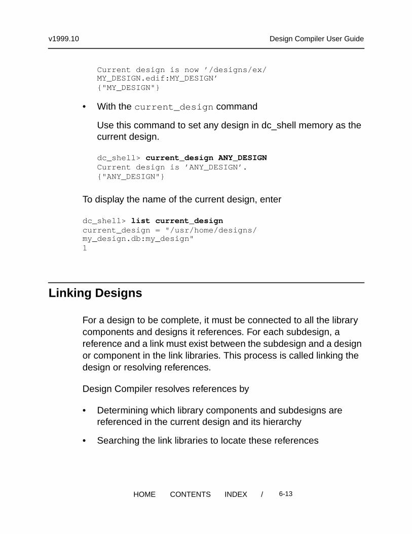
Current design is now ’/designs/ex/MY_DESIGN.edif:MY_DESIGN’{"MY_DESIGN"}
• With the current_design command
Use this command to set any design in dc_shell memory as thecurrent design.
dc_shell> current_design ANY_DESIGNCurrent design is ’ANY_DESIGN’.{"ANY_DESIGN"}
To display the name of the current design, enter
dc_shell> list current_designcurrent_design = "/usr/home/designs/my_design.db:my_design"1
Linking Designs
For a design to be complete, it must be connected to all the librarycomponents and designs it references. For each subdesign, areference and a link must exist between the subdesign and a designor component in the link libraries. This process is called linking thedesign or resolving references.
Design Compiler resolves references by
• Determining which library components and subdesigns arereferenced in the current design and its hierarchy
• Searching the link libraries to locate these references
/ 6-13HOME CONTENTS INDEX

v1999.10 Design Compiler User Guide
Design Compiler first searches the libraries and design filesdefined in the current design’s local_link_library attribute,then searches the libraries and design files defined in thelink_library variable. See Chapter 5, “Working WithLibraries,” for more information about link libraries.
Note:
In a hierarchical design, Design Compiler considers only thetop-level design’s local link library. It ignores local link librariesassociated with the subdesigns.
Design Compiler uses the first reference it locates. If it locatesadditional references with the same name, it generates a warningmessage identifying the ignored, duplicate references. If DesignCompiler does not find the reference, a warning appears advisingthat the reference cannot be resolved.
• Connecting the located references to the design
By default, the case sensitivity of the link process depends on thesource of the references. To explicitly define the case sensitivity ofthe link process, set the link_force_case variable.
The arrows in Figure 6-4 show the connections the linking processadded between the cells, references, and link libraries. In thisexample, Design Compiler finds library component NAND2 in theLIBRARY_2 technology library; it finds subdesign MULTIPLIER in adesign file.
/ 6-14HOME CONTENTS INDEX

v1999.10 Design Compiler User Guide
Figure 6-4 Resolving References
You can link the design either manually or automatically. The followingsections describe these tasks.
Linking a Design Manually
Use the link command to manually link a design. The linkcommand removes existing links before starting the link process.
Linking a Design Automatically
The following dc_shell commands automatically link designs:
• compile
• create_schematic
• group
• check_design
• report
References
NAND2
MULTIPLIER
NAND2
U1
NAND2
U3
NAND2
U2
U4
EXREF Link Libraries
LIBRARY_1
LIBRARY_2
Technology Libraries
MULTIPLIER
ADDER
Design Files
AND2NAND2OR2
MULTIPLIER
/ 6-15HOME CONTENTS INDEX

v1999.10 Design Compiler User Guide
• compare_design
When Design Compiler links automatically, it does not removeexisting links. The automatic link process works only on unlinkedcomponents and subdesigns.
Changing Design References
Use the change_link command to change the component ordesign to which a cell or reference is linked.
• For a cell, the link for that cell is changed.
• For a reference, the link is changed for all cells having thatreference.
The link can be changed only to a component or design that has thesame number of ports with the same size and direction as the originalreference.
When you use change_link , all link information is copied from theold design to the new design. If the old design is a synthetic module,all attributes of the old synthetic module are moved to the new link.After using change_link , manually link the design with the linkcommand.
Listing Design Objects
Design Compiler provides commands for accessing various designobjects. These commands refer to design objects located in thecurrent design. Each command performs one of the following actions:
• List
/ 6-16HOME CONTENTS INDEX

v1999.10 Design Compiler User Guide
Provides a listing with minimal information.
• Display
Provides a report including characteristics of the design object.
• Return
Returns a list that can be used as input to another dc_shellcommand.
Table 6-3 lists these commands and the actions they perform.
Table 6-3 Commands to Access Design Objects
Object Command Action
Instance list_instancesreport_cell
Lists instances and their references.Displays information about instances.
Reference report_reference Displays information aboutreferences.
Port report_portreport_bus
all_inputsall_outputs
Displays information about ports.Displays information about busedports.Returns all input ports.Returns all output ports.
Net report_netreport_bus
Displays information about nets.Displays information about busednets.
Clock report_clockall_clocks
Displays information about clocks.Returns all clocks.
/ 6-17HOME CONTENTS INDEX

v1999.10 Design Compiler User Guide
Specifying Design Objects
You can specify design objects by using either a relative path or anabsolute path.
Using a Relative Path
If you use a relative path to specify a design object, the object mustbe in the current design. Specify the path relative to the currentinstance. The current instance is the frame of reference within thecurrent design. By default, the current instance is the top level of thecurrent design. Use the current_instance command to changethe current instance.
For example, to place a dont_touch attribute on hierarchical cellU1/U15 in the Count_16 design, you can enter either
dc_shell> current_design Count_16Current design is ’Count_16’.{"Count_16"}dc_shell> set_dont_touch U1/U15
or
dc_shell> current_design Count_16Current design is ’Count_16’.
Register all_registers Returns all registers.
Table 6-3 Commands to Access Design Objects (continued)
Object Command Action
/ 6-18HOME CONTENTS INDEX

v1999.10 Design Compiler User Guide
{"Count_16"}dc_shell> current_instance U1Current instance is ’/Count_16/U1’."/Count_16/U1"dc_shell> set_dont_touch U15
In the first command sequence, the frame of reference remains at thetop level of design Count_16. In the second command sequence, theframe of reference changes to instance U1. Design Compilerinterprets all future object specifications relative to instance U1.
To reset the current instance to the top level of the current design,enter the current_instance command without an argument.
dc_shell> current_instance
The current_instance variable points to the current instance. Thecurrent_reference variable points to the reference of the currentinstance. To display the current instance and its reference, enter
dc_shell> list current_instancecurrent_instance = "Count_16/U1"1dc_shell> list current_referencecurrent_reference = "/usr/designs/Count_16.db:Count_4"1
Using an Absolute Path
When you use an absolute path to specify a design object, the objectcan be in any design in dc_shell memory. Use the following syntaxwhen specifying an object by using an absolute path:
/ 6-19HOME CONTENTS INDEX

v1999.10 Design Compiler User Guide
[ file :] design/object
file
The path name of a memory file followed by a colon (:). Use thefile argument when multiple designs in memory have the samename.
design
The name of a design in dc_shell memory.
object
The name of the design object, including its hierarchical path. Ifseveral objects of different types have the same name, DesignCompiler uses the default search order unless you specify theobject type.
To specify an object type, use the find command. For moreinformation about the find command, see the Design CompilerCommand-Line Interface Guide.
For example, to place a dont_touch attribute on hierarchical cellU1/U15 in the Count_16 design, enter
dc_shell> set_dont_touch \/usr/designs/Count_16.db:Count_16/U1/U5
Creating Designs
The create_design command creates a new design. The memoryfile name is design.db, and the path is the current working directory.
dc_shell> create_design my_designCreating design ’my_design’ in file ’my_design.db’.1
/ 6-20HOME CONTENTS INDEX

v1999.10 Design Compiler User Guide
dc_shell> list_designs -show_file
/designs/A.dbA (*)
/designs/B.dbB
/usr/work/my_design.dbmy_design1
Designs created with create_design contain no design objects.Use the appropriate create commands (such as create_clock,create_cell, or create_port) to add design objects to the new design.See “Editing Designs” on page 6-29 for information about thesecommands.
Copying Designs
The copy_design command copies a design in memory andrenames the copy. The new design has the same path and memoryfile as the original design.
dc_shell> copy_design A A_NEWCopying design ’A’ to ’A_NEW’1dc_shell> list_designs -show_file
/designs/A.dbA A_NEW
/designs/B.dbB1
/ 6-21HOME CONTENTS INDEX

v1999.10 Design Compiler User Guide
You can use the copy_design command with the change_linkcommand to manually create unique instances. For example, assumethat a design has two identical cells, U1 and U2, both linked to COMP.Enter the following commands to create unique instances:
dc_shell> copy_design COMP COMP1Performing copy_design on design ’COMP’.Copying design ’COMP’ to ’COMP1’1dc_shell> change_link U1 COMP1Performing change_link on cell ’U1’.1dc_shell> copy_design COMP COMP2Performing copy_design on design ’COMP’.Copying design ’COMP’ to ’COMP2’1dc_shell> change_link U2 COMP2Performing change_link on cell ’U2’.1
Renaming Designs
The rename_design command renames a design in memory.
dc_shell> list_designs -show_file
/designs/X.dbA B1dc_shell> rename_design A A_NEWMoving design ’A’ to ’A_NEW’1dc_shell> list_designs -show_file
/designs/X.dbA_NEW B1
/ 6-22HOME CONTENTS INDEX

v1999.10 Design Compiler User Guide
Note:Renaming designs might cause unresolved references duringlinking.
Changing the Design Hierarchy
When possible, reflect the design partitioning in your HDL description.If your HDL code is already developed, Design Compiler allows youto change the hierarchy without modifying the HDL description.
The report_hierarchy command displays the design hierarchy.Use this command to understand the current hierarchy before makingchanges and to verify the hierarchy changes.
Design Compiler provides the following hierarchy manipulationcapabilities:
• Adding levels of hierarchy
• Removing levels of hierarchy
• Merging cells from different subdesigns
The following sections describe these capabilities.
Adding Levels of Hierarchy
Adding a level of hierarchy is called grouping. You can create a levelof hierarchy by grouping cells or related components into subdesigns.
/ 6-23HOME CONTENTS INDEX

v1999.10 Design Compiler User Guide
Grouping Cells Into Subdesigns
The group command groups cells (instances) in the design into anew subdesign, creating a new level of hierarchy. The grouped cellsare replaced by a new instance (cell) that references the newsubdesign.
The ports of the new subdesign are named after the nets to whichthey are connected in the design. The direction of each port of thenew subdesign is determined from the pins of the corresponding net.
To create a new subdesign,
• Specify the cells included in the new subdesign as the command-line argument.
All cells must be children of the current instance. You can excludecells from the specified list by using the -except option.
• Specify the name of the new subdesign, using the -design_name option.
• Specify the new instance name, using the -cell_name option.(optional)
If you do not specify an instance name, Design Compiler createsone for you. The created instance name has the format Un, wheren is an unused cell number (for example, U107).
For example, to group three cells into a new design named sample,enter
dc_shell> group {cell1, cell2, cell3} -design_name sample
To group all cells that begin with alu into a new design uP with cellname UCELL, enter
/ 6-24HOME CONTENTS INDEX

v1999.10 Design Compiler User Guide
dc_shell> group "alu*" -design_name uP -cell_name UCELL
Grouping Related Components Into Subdesigns
You also use the group command (but with different options) to grouprelated components into subdesigns.
To group related components,
• Specify the component type, using one of the options shown inTable 6-4.
• Specify the name of the new subdesign, using the -design_nameoption.
• Specify the new instance name, using the -cell_name option(optional).
If you do not specify an instance name, Design Compiler createsone for you. The created instance name has the format Un, wheren is an unused cell number (for example, U107).
Table 6-4 Component Grouping Options
Component Options
Bused gates -hdl_bussed
Combinational logic -logic
Finite state machines -fsm
HDL blocks -hdl_all_blocks-hdl_block block_name
PLA specifications -pla
/ 6-25HOME CONTENTS INDEX

v1999.10 Design Compiler User Guide
For example, to group all cells in the HDL function bar in the processftj into design new_block, enter
dc_shell> group -hdl_block ftj/bar -design_name new_block
To group all bused gates beneath process ftj into separate levels ofhierarchy, enter
dc_shell> group -hdl_block ftj -hdl_bussed
Removing Levels of Hierarchy
Removing a level of hierarchy is called ungrouping. Ungroupingremoves (or collapses) the level of hierarchy of the identifiedsubdesign and merges the subdesign with the surrounding logic.
You can ungroup designs in two ways:
• Immediately, using the ungroup command to directly ungroupdesigns
• During optimization, using the set_ungroup command or usingthe -ungroup_all option when you run the compile command
Designs that have the dont_touch attribute cannot be ungrouped.
Ungrouping Designs Directly
The ungroup command immediately ungroups one or more designs.
To ungroup a design,
• Specify the cells to be ungrouped as the command-line argument.
/ 6-26HOME CONTENTS INDEX

v1999.10 Design Compiler User Guide
All cells must be children of the current instance. To ungroup allhierarchical children of the current instance, specify the -all optioninstead of providing a cell list.
By default, the ungroup command ungroups only one level ofhierarchy in each cell. To ungroup each cell recursively until alllevels of hierarchy are removed, specify the -flatten option.
• Specify the prefix for the ungrouped cells (optional).
If you do not specify a prefix, Design Compiler uses the prefixold_cell_name/. When you use the -flatten option, do notspecify a prefix, because the default cell names are moredescriptive than cell names generated with a specified prefix.
If the specified or default prefix creates a nonunique name, DesignCompiler adds a number to the end of the cell name to make itunique.
For example, to ungroup several cells, enter
dc_shell> ungroup {high_decoder_cell, low_decoder_cell}
To ungroup the cell U1 and specify the prefix to use when creatingnew cells, enter
dc_shell> ungroup U1 -prefix "U1_"
To completely flatten the current design, enter
dc_shell> ungroup -all -flatten
/ 6-27HOME CONTENTS INDEX

v1999.10 Design Compiler User Guide
Ungrouping Designs During Optimization
To remove all levels of hierarchy during optimization (includingDesignWare parts), use the -ungroup_all option when you run thecompile command.
dc_shell> compile -ungroup_all
To ungroup specific cells or designs, use the set_ungroupcommand before running the compile command. Theset_ungroup command sets the ungroup attribute on the specifiedcells or designs. If you set the ungroup attribute on a cell, duringoptimization Design Compiler ungroups that cell. If you set theungroup attribute on a design, during optimization Design Compilerungroups all cells that reference that design.
For example, to ungroup cell U1 during optimization, enter thefollowing commands:
dc_shell> set_ungroup U1dc_shell> compile
To see whether an object has the ungroup attribute set, use theget_attribute command.
dc_shell> get_attribute object ungroup
To remove an ungroup attribute, use the remove_attributecommand or set the ungroup attribute to false.
dc_shell> set_ungroup object false
/ 6-28HOME CONTENTS INDEX

v1999.10 Design Compiler User Guide
Merging Cells From Different Subdesigns
To merge cells from different subdesigns into a new subdesign,
1. Group the cells into a new design.
2. Ungroup the new design.
For example, this command sequence creates a new design, alu, thatcontains the cells that initially were in subdesigns u_add and u_mult.
dc_shell> group {u_add, u_mult} -design aludc_shell> current_design = aludc_shell> ungroup -alldc_shell> current_design = top_design
Editing Designs
Design Compiler provides commands for incrementally editing adesign that is in memory. These commands allow you to change thenetlist or edit designs by using dc_shell commands instead of anexternal format.
Table 6-5 Commands to Edit Designs
Object Task Command
Cells Create a cellDelete a cell
create_cellremove_cell
Nets Create a netConnect a netDisconnect a netDelete a net
create_netconnect_netdisconnect_netremove_net
/ 6-29HOME CONTENTS INDEX

v1999.10 Design Compiler User Guide
When connecting or disconnecting nets, use the all_connectedcommand to see the objects that are connected to a net, port, or pin.
For example, this sequence of dc_shell commands replaces thereference for cell U8 with a high-power inverter.
dc_shell> find(pin, U8/*){"U8/A", "U8/Z"}dc_shell> all_connected U8/A{"n66"}dc_shell> all_connected U8/Z{"OUTBUS[10]"}dc_shell> remove_cell U8Removing cell ’U8’ in design ’top’.1dc_shell> create_cell U8 IVPCreating cell ’U8’ in design ’top’.1dc_shell> connect_net n66 find(pin,U8/A)Connecting net ’n66’ to pin ’U8/A’.1dc_shell> connect_net OUTBUS[10] find(pin,U8/Z)Connecting net ’OUTBUS[10]’ to pin ’U8/Z’.1
Ports Create a portDelete a port
create_portremove_port
Buses Create a busDelete a bus
create_busremove_bus
Table 6-5 Commands to Edit Designs (continued)
Object Task Command
/ 6-30HOME CONTENTS INDEX

v1999.10 Design Compiler User Guide
Translating Designs From One Technology to Another
The translate command translates a design from one technologyto another.
Designs are translated cell by cell from the original technology libraryto a new technology library, preserving the gate structure of theoriginal design. The translator uses the functional description of eachexisting cell (component) to determine the matching component inthe new technology library (target library). If no exact replacementexists for a component, it is remapped with components from thetarget library.
You can influence the replacement-cell selection by preferring ordisabling specific library cells (set_prefer and set_dont_usecommands) and by specifying the types of registers(set_register_type command). The target libraries are specifiedin the target_library variable. The local_link_library ofthe top-level design is set to the target_library value after thedesign is linked.
The translate command does not operate on cells or designshaving the dont_touch attribute. After the translation process,Design Compiler reports cells that are not successfully translated.During the verification phase, Design Compiler applies thecompare_design script.
Procedure to Translate Designs
This procedure works for most designs, but manual intervention mightbe necessary for some complex designs.
/ 6-31HOME CONTENTS INDEX

v1999.10 Design Compiler User Guide
To translate a design,
1. Read in your mapped design.
dc_shell> read_file design.db
2. Set the target library to the new technology library.
dc_shell> target_library = { target_lib.db }
3. Set timing constraints based on the current design performance.
dc_shell> derive_timing_constraints
4. Invoke the translate command.
dc_shell> translate
After a design is translated, you can optimize it (using the compilecommand) to improve the implementation in the new technologylibrary.
Restrictions When Translating Between Technologies
Keep these restrictions in mind when you translate a design from onetechnology to another:
• The translate command translates functionality logically butdoes not preserve drive strength during translation. It always usesthe lowest drive strength version of a cell, which might produce anetlist with violations.
• When you translate CMOS three-state cells into FPGA, functionalequivalents between the technologies might not exist.
/ 6-32HOME CONTENTS INDEX

v1999.10 Design Compiler User Guide
• Buses driven by CMOS three-state components must be fullydecoded (Design Compiler can assume that only one bus driveris ever active). If this is the case, bus drivers are translated intocontrol logic. To enable this feature, set thecompile_assume_fully_decoded_three_state_busesvariable to true before translating.
• If a three-state bus within a design is connected to one or moreoutput ports, translating the bus to a multiplexed signal changesthe port functionality. Because translate does not change portfunctionality, this case is reported as a translation error.
Removing Designs From Memory
The remove_design command removes designs from dc_shellmemory. For example, after completing a compilation session andsaving the optimized design, you can use remove_design to deletethe design from memory before reading in another design.
By default, the remove_design command removes only thespecified design. To remove its subdesigns, specify the -hierarchyoption. To remove all designs (and libraries) from memory, specifythe -all option.
If you defined variables that reference design objects, DesignCompiler removes these references when you remove the designfrom memory. This prevents future commands from attempting tooperate on nonexistent design objects. For example,
dc_shell> PORTS = all_inputs(){"A0", "A1", "A2", "A3"}dc_shell> list PORTSPORTS = {"A0", "A1", "A2", "A3"}dc_shell> remove_design
/ 6-33HOME CONTENTS INDEX

v1999.10 Design Compiler User Guide
Removing design ’top’1dc_shell> list PORTSPORTS = {}
Saving Designs
You can save (write to disk) the design and its subdesigns in thehierarchy at any time and to a different name or format. After youmodify a design, you must save that design. Design Compiler doesnot automatically save designs when you exit.
Table 6-6 on page 6-37 lists the design file formats supported byDesign Compiler. All formats except .db, EDIF, equation, PLA, andstate table require special license keys.
The write command converts designs in memory to a format youspecify and saves that representation to disk. By default, DesignCompiler saves the current design in .db format to the file./ design_name.db.
dc_shell> write
When writing to formats other than .db, consider the namingrequirements of the target environment. You might have to performone or more of the following tasks before saving the design:
• If the target environment has restrictions on the design objectnames, use the change_names command to modify the names.
• If the target environment has specific requirements for busdelimiters, set the bus_naming_style variable to meet thoserequirements.
/ 6-34HOME CONTENTS INDEX
v1999.10 Design Compiler User Guide
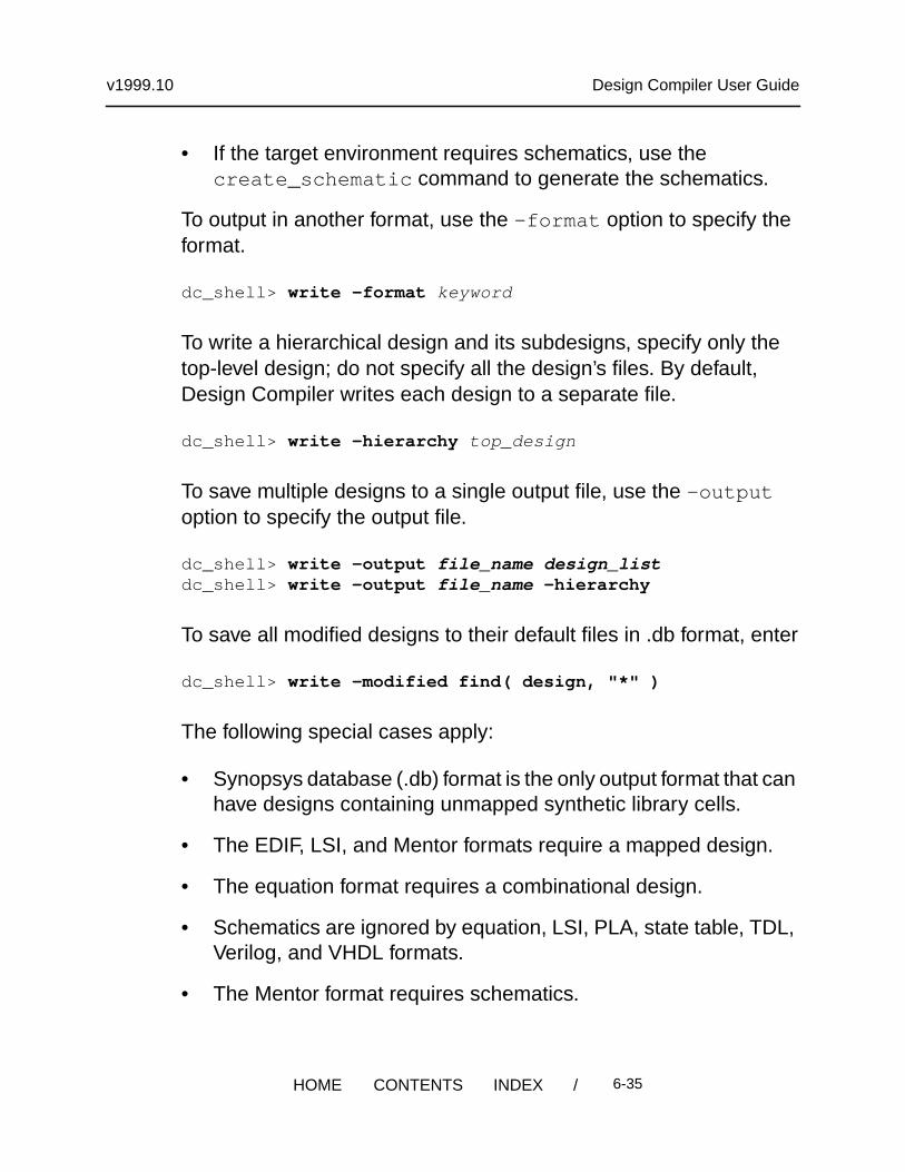
• If the target environment requires schematics, use thecreate_schematic command to generate the schematics.
To output in another format, use the -format option to specify theformat.
dc_shell> write -format keyword
To write a hierarchical design and its subdesigns, specify only thetop-level design; do not specify all the design’s files. By default,Design Compiler writes each design to a separate file.
dc_shell> write -hierarchy top_design
To save multiple designs to a single output file, use the -outputoption to specify the output file.
dc_shell> write -output file_name design_listdc_shell> write -output file_name -hierarchy
To save all modified designs to their default files in .db format, enter
dc_shell> write -modified find( design, "*" )
The following special cases apply:
• Synopsys database (.db) format is the only output format that canhave designs containing unmapped synthetic library cells.
• The EDIF, LSI, and Mentor formats require a mapped design.
• The equation format requires a combinational design.
• Schematics are ignored by equation, LSI, PLA, state table, TDL,Verilog, and VHDL formats.
• The Mentor format requires schematics.
/ 6-35HOME CONTENTS INDEX

v1999.10 Design Compiler User Guide
Working With Attributes
Attributes describe logical, electrical, physical, and other propertiesof objects in the design database. An attribute is attached to a designobject and is saved with the design database.
Design Compiler uses attributes on the following types of objects:
• Entire designs
• Design objects, such as clocks, nets, pins, and ports
• Design references and cell instances within a design
• Technology libraries, library cells, and cell pins
An attribute has a name, a type, and a value. Attributes can have thefollowing types: string, numeric, or logical (Boolean).
Some attributes are predefined and are recognized by DesignCompiler; other attributes are user-defined. Appendix C lists thepredefined attributes.
Some attributes are read-only. Design Compiler sets these attributevalues and you cannot change them. Other attributes are read/write.You can change these attribute values at any time.
Most attributes apply to one object type; for example, therise_drive attribute applies only to input and inout ports. Someattributes apply to several object types; for example, the dont_touch
/ 6-36HOME CONTENTS INDEX

v1999.10 Design Compiler User Guide
attribute can apply to a net, cell, port, reference, or design. You canget detailed information about the predefined attributes that apply toeach object type by using the commands listed in Table 6-6.
Setting Attribute Values
To set the value of an attribute, use
• An attribute-specific command
Use an attribute-specific command to set the value of itsassociated attribute.
For example,
dc_shell> set_dont_touch U1
Table 6-6 Commands to Get Attribute Descriptions
Object Type Command
All help attributes
Designs help design_attributes
Cells help cell_attributes
Clocks help clock_attributes
Nets help net_attributes
Pins help pin_attributes
Ports help port_attributes
Libraries help library_attributes
Library cells help library_cell_attributes
References help reference_attributes
/ 6-37HOME CONTENTS INDEX

v1999.10 Design Compiler User Guide
• The set_attribute command
Use this command to set the value of any attribute or to define anew attribute and set its value.
For example, to set the flatten attribute to false on design top,enter
dc_shell> set_attribute top flatten false
If an attribute applies to more than one object type, Design Compilersearches the database for the named object. See “Understanding theObject Search Order” on page 6-41 for information about the searchorder.
When you set an attribute on a reference (subdesign or library cell),the attribute applies to all cells in the design with that reference. Whenyou set an attribute on an instance (cell, net, or pin), the attributeoverrides any attribute inherited from its reference.
Viewing Attribute Values
To see all attributes on an object, use the report_attributecommand.
dc_shell> report_attribute -object obj_type
To see the value of a specific attribute on an object, use theget_attribute command.
For example, to get the value of the maximum fanout on port OUT7,enter
dc_shell> get_attribute OUT7 max_fanoutPerforming get_attribute on port ’OUT7’.
/ 6-38HOME CONTENTS INDEX

v1999.10 Design Compiler User Guide
{3.000000}
If an attribute applies to more than one object type, Design Compilersearches the database for the named object. See “Understanding theObject Search Order” on page 6-41 for information about the searchorder.
Saving Attribute Values
Design Compiler does not automatically save attribute values whenyou exit dc_shell. Use the write_script command to generate adc_shell script that recreates the attribute values.
Note:The write_script command does not support user-definedattributes.
By default, write_script prints to the screen. Use the redirectionoperator (>) to redirect the output to a file.
dc_shell> write_script > attr.scr
Defining Attributes
The set_attribute command enables you to create newattributes. Use the set_attribute command described in “SettingAttribute Values” on page 6-37.
If you want to change the value type of an attribute, remove theattribute and then re-create it to store the desired type.
/ 6-39HOME CONTENTS INDEX

v1999.10 Design Compiler User Guide
Removing Attributes
To remove a specific attribute from an object, use theremove_attribute command.
You cannot use the remove_attribute command to removeinherited attributes. For example, if a dont_touch attribute isassigned to a reference, remove the attribute from the reference, notfrom the cells that inherited the attribute.
For example, to remove the max_fanout attribute from the portOUT7, enter
dc_shell> remove_attribute OUT7 max_fanoutPerforming remove_attribute on port ’OUT7’.{OUT7}
You can remove selected attributes by using the commands that setthem. Some set_* commands provide a -default option thatremoves from the current design the attributes previously set by thecommand. See the man page for a specific command to determinewhether it has the -default option.
To remove all attributes from the current design, use thereset_design command.
dc_shell> reset_designResetting current design ’EXAMPLE’.1
The reset_design command removes all design information,including clocks, input and output delays, path groups, operatingconditions, timing ranges, and wire load models. The result of usingreset_design is often equivalent to starting the design processfrom the beginning.
/ 6-40HOME CONTENTS INDEX

v1999.10 Design Compiler User Guide
Understanding the Object Search Order
Design Compiler searches for an object, X, in the following order:
1. Design X
2. Cell X
3. Net X
4. Reference X
5. Library cell X
Commands that can set an attribute on more than one type of objectuse this search order to determine the object to which the attributeapplies.
For example, the set_dont_touch command operates on cells,nets, references, and library cells. If you define an object, X, with theset_dont_touch command and two objects (such as the designand a cell) are named X, Design Compiler applies the attribute to thefirst object type found. In this case, the attribute is set on the design,not on the cell.
Design Compiler stops searching when it finds a matching object, orit displays an error message if it does not find a matching object.
Design Compiler echoes the type of object on which an attribute isset. (If you do not want the echo, set verbose_messages = false .)
dc_shell> set_dont_touch XPerforming set_dont_touch on design ’X’.1
/ 6-41HOME CONTENTS INDEX
v1999.10 Design Compiler User Guide
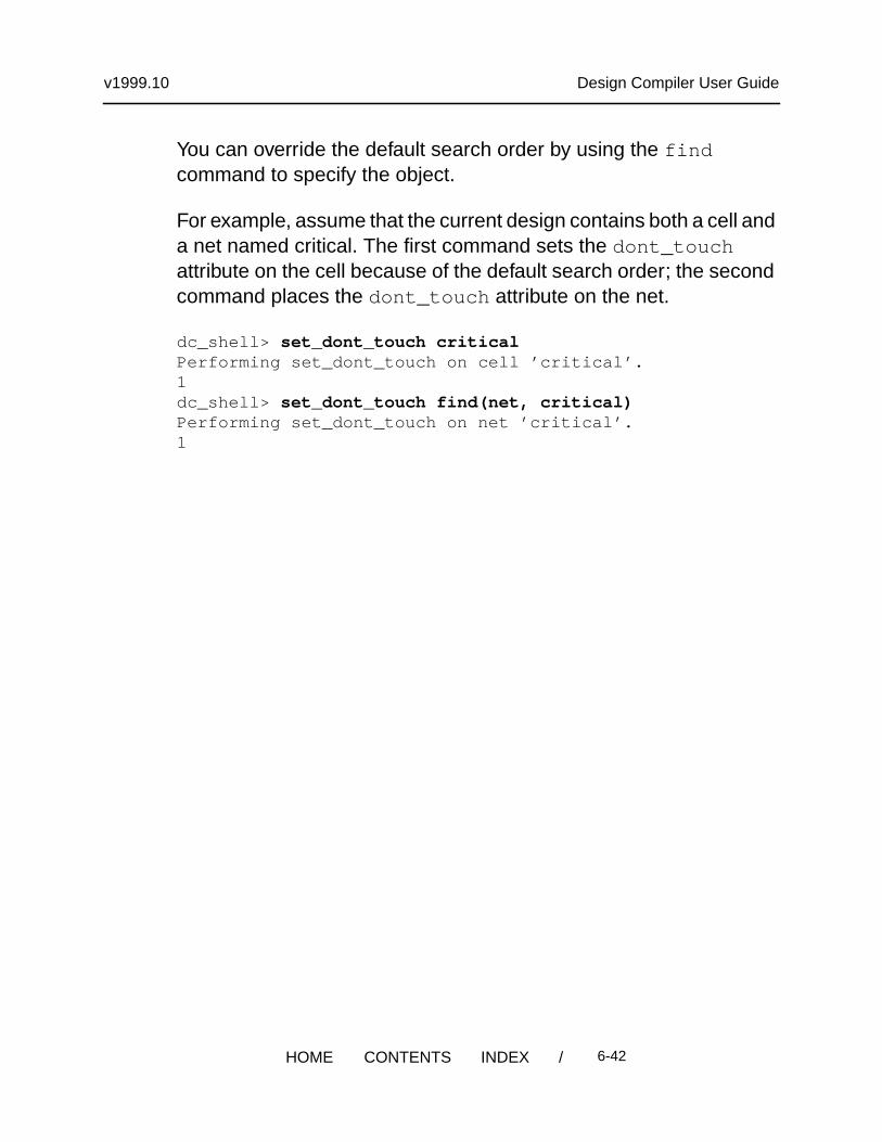
You can override the default search order by using the findcommand to specify the object.
For example, assume that the current design contains both a cell anda net named critical. The first command sets the dont_touchattribute on the cell because of the default search order; the secondcommand places the dont_touch attribute on the net.
dc_shell> set_dont_touch criticalPerforming set_dont_touch on cell ’critical’.1dc_shell> set_dont_touch find(net, critical)Performing set_dont_touch on net ’critical’.1
/ 6-42HOME CONTENTS INDEX