
Working Final FERC App update 4 29 2013
40
Baker County Mason Dam Hydroelectric Project FERC No. P-12686 Erosion and Sediment Control Plan October 2010 253
Transcript of Working Final FERC App update 4 29 2013
Baker CountyMason Dam Hydroelectric Project
FERC No. P-12686
Erosion and Sediment Control Plan
October 2010
253

Table of Contents
I. Introduction 1.0 Purpose and Scope 2.0 References 3.0 Definitions4.0 Responsibilities5.0 Procedure6.0 Summary of Mitigation Measures 7.0 Attachments
254
I. Introduction
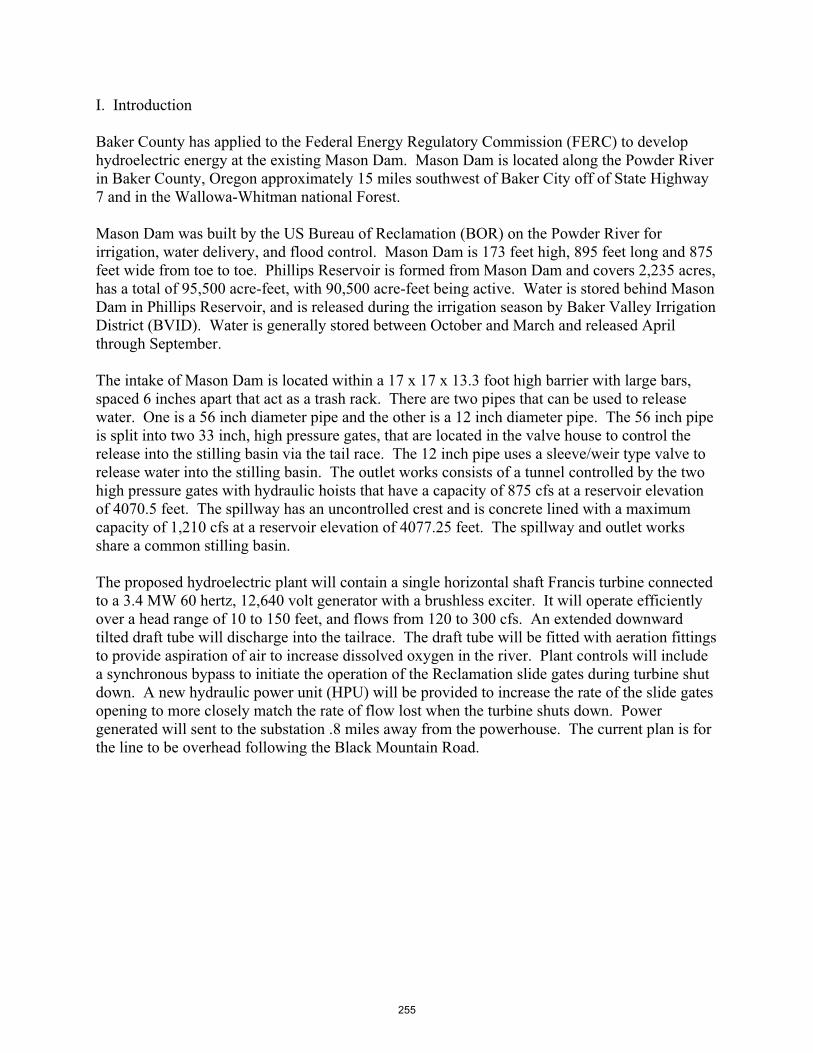
Baker County has applied to the Federal Energy Regulatory Commission (FERC) to develop hydroelectric energy at the existing Mason Dam. Mason Dam is located along the Powder River in Baker County, Oregon approximately 15 miles southwest of Baker City off of State Highway 7 and in the Wallowa-Whitman national Forest.
Mason Dam was built by the US Bureau of Reclamation (BOR) on the Powder River for irrigation, water delivery, and flood control. Mason Dam is 173 feet high, 895 feet long and 875 feet wide from toe to toe. Phillips Reservoir is formed from Mason Dam and covers 2,235 acres, has a total of 95,500 acre-feet, with 90,500 acre-feet being active. Water is stored behind Mason Dam in Phillips Reservoir, and is released during the irrigation season by Baker Valley Irrigation District (BVID). Water is generally stored between October and March and released April through September.
The intake of Mason Dam is located within a 17 x 17 x 13.3 foot high barrier with large bars, spaced 6 inches apart that act as a trash rack. There are two pipes that can be used to release water. One is a 56 inch diameter pipe and the other is a 12 inch diameter pipe. The 56 inch pipe is split into two 33 inch, high pressure gates, that are located in the valve house to control the release into the stilling basin via the tail race. The 12 inch pipe uses a sleeve/weir type valve to release water into the stilling basin. The outlet works consists of a tunnel controlled by the two high pressure gates with hydraulic hoists that have a capacity of 875 cfs at a reservoir elevation of 4070.5 feet. The spillway has an uncontrolled crest and is concrete lined with a maximum capacity of 1,210 cfs at a reservoir elevation of 4077.25 feet. The spillway and outlet works share a common stilling basin.
The proposed hydroelectric plant will contain a single horizontal shaft Francis turbine connected to a 3.4 MW 60 hertz, 12,640 volt generator with a brushless exciter. It will operate efficiently over a head range of 10 to 150 feet, and flows from 120 to 300 cfs. An extended downward tilted draft tube will discharge into the tailrace. The draft tube will be fitted with aeration fittings to provide aspiration of air to increase dissolved oxygen in the river. Plant controls will include a synchronous bypass to initiate the operation of the Reclamation slide gates during turbine shut down. A new hydraulic power unit (HPU) will be provided to increase the rate of the slide gates opening to more closely match the rate of flow lost when the turbine shuts down. Power generated will sent to the substation .8 miles away from the powerhouse. The current plan is for the line to be overhead following the Black Mountain Road.
255
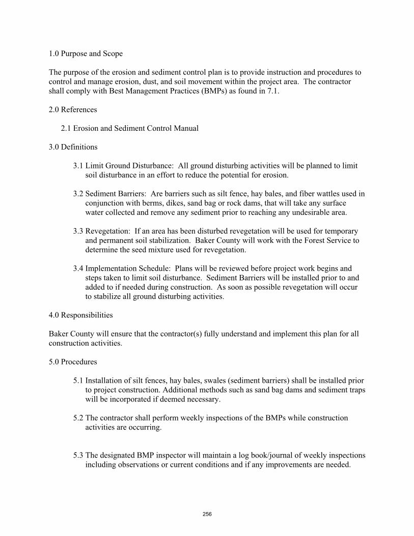
1.0 Purpose and Scope
The purpose of the erosion and sediment control plan is to provide instruction and procedures to control and manage erosion, dust, and soil movement within the project area. The contractor shall comply with Best Management Practices (BMPs) as found in 7.1.
2.0 References
2.1 Erosion and Sediment Control Manual
3.0 Definitions
3.1 Limit Ground Disturbance: All ground disturbing activities will be planned to limit soil disturbance in an effort to reduce the potential for erosion.
3.2 Sediment Barriers: Are barriers such as silt fence, hay bales, and fiber wattles used in conjunction with berms, dikes, sand bag or rock dams, that will take any surface water collected and remove any sediment prior to reaching any undesirable area.
3.3 Revegetation: If an area has been disturbed revegetation will be used for temporary and permanent soil stabilization. Baker County will work with the Forest Service to determine the seed mixture used for revegetation.
3.4 Implementation Schedule: Plans will be reviewed before project work begins and steps taken to limit soil disturbance. Sediment Barriers will be installed prior to and added to if needed during construction. As soon as possible revegetation will occur to stabilize all ground disturbing activities.
4.0 Responsibilities
Baker County will ensure that the contractor(s) fully understand and implement this plan for all construction activities.
5.0 Procedures
5.1 Installation of silt fences, hay bales, swales (sediment barriers) shall be installed prior to project construction. Additional methods such as sand bag dams and sediment traps will be incorporated if deemed necessary.
5.2 The contractor shall perform weekly inspections of the BMPs while construction activities are occurring.
5.3 The designated BMP inspector will maintain a log book/journal of weekly inspections including observations or current conditions and if any improvements are needed.
256
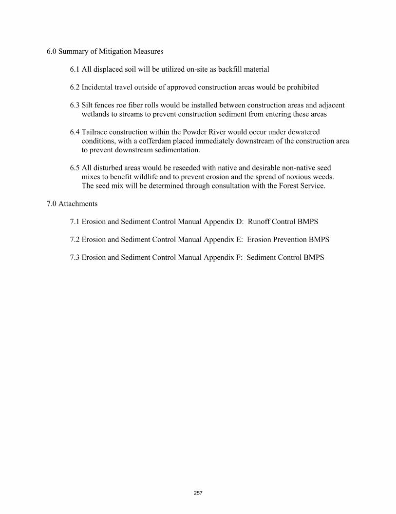
6.0 Summary of Mitigation Measures
6.1 All displaced soil will be utilized on-site as backfill material
6.2 Incidental travel outside of approved construction areas would be prohibited
6.3 Silt fences roe fiber rolls would be installed between construction areas and adjacent wetlands to streams to prevent construction sediment from entering these areas
6.4 Tailrace construction within the Powder River would occur under dewatered conditions, with a cofferdam placed immediately downstream of the construction area to prevent downstream sedimentation.
6.5 All disturbed areas would be reseeded with native and desirable non-native seed mixes to benefit wildlife and to prevent erosion and the spread of noxious weeds.The seed mix will be determined through consultation with the Forest Service.
7.0 Attachments
7.1 Erosion and Sediment Control Manual Appendix D: Runoff Control BMPS
7.2 Erosion and Sediment Control Manual Appendix E: Erosion Prevention BMPS
7.3 Erosion and Sediment Control Manual Appendix F: Sediment Control BMPS
257

Oregon DEQ
OREGON MANUAL-APPENDICES.DOC Erosion and Sediment Control ManualApril 28, 2005
APPENDIX D
RUNOFF CONTROL BMPS
RC-1 Slope Drain RC-2 Energy Dissipator RC-3 Diversion of Run-on RC-4 Temporary Diversion Dike RC-5 Grass-lined Channel (Turf Reinforcement Mats) RC-6 Trench Drain RC-7 Drop Inlet RC-8 Minimizing TSS During Instream Construction RC-9 Instream Diversion Techniques RC-10 Instream Isolation Techniques RC-11 Check Dams
Attachment 7.1
258

SLOPE DRAIN – RC-1
Page 1 of 2
Construction Specifications:
A common failure of slope drains is caused by water saturating the soil and seeping along the pipe. Proper backfilling around and under the pipe haunches with stable soil material and hand compacting in 6 inch (0.2 m) lifts to achieve firm contact between the pipe and the soil at all points will reduce this type of failure.
� Place slope drains on undisturbed soil or well-compacted fill at locations and elevations shown on the plans.
� Slightly slope the section of pipe under the dike toward its outlet.
� Compact the soil under and around the entrance section in lifts not to exceed 6 inches.
� Ensure that fill over the drain at the top of the slope has a minimum depth of 1.5 feet (0.5 m) and a minimum top width of 4 feet (1.2 m). The sides should have a 3:1 slope.
� Ensure that all slope drain connections are watertight.
� Ensure that all fill material is well-compacted. Securely fasten the exposed section of the drain with grommets or stakes spaced no more than 10 feet (3.1 m) apart. If the drain is longer than 10 feet (3.1 m), the drain must be anchored within each 10 foot (3.1 m) section and at the end section. Anchoring methods can vary depending on site conditions. At a minimum, the drain should be staked such that it is not able to move laterally or separate from the upstream diversion culvert.
� Extend the drain beyond the toe of the slope and adequately protect the outlet from erosion (see EC-10).
� Make the settled, compacted dike ridge no less than 1 foot (0.3 m) higher than the top of the pipe inlet.
� As an alternative to slope drains visqueen flume down drains may be used to convey runoff to a stabilized downstream conveyance. The visqueen shall be anchored at the top of a slope similar to erosion control blankets (EC-10). Use sandbags to stabilize the sides of the visqueen flume similar to sand bag barriers (SC-2). The visqueen (plastic sheet) shall meet the following specifications:
o Plastic sheeting shall have a minimum thickness of 6 mil, and shall be keyed in at the top of slope and firmly held in place with sandbags or other weights placed no more than 10 ft (3 m) apart. Seams are typically taped or weighted down their entire length, and there shall be at least a 12 to 24 inches (300 mm to 600 mm) overlap of all seams. Edges shall be embedded a minimum of 6 inches (150 mm) in soil.
o All sheeting shall be inspected periodically after installation and after significant rainstorms to check for erosion, undermining, and anchorage failure. Any failures shall be repaired immediately. If washout or breakages occurs, the material shall be re-installed after repairing the damage to the slope.
� Immediately after grading, stabilize all disturbed areas as appropriate (see Erosion Prevention BMPs).
Minimum BMP standards are provided on the following detail. Inspection and Maintenance:
� Inspect the slope drain and supporting diversions before, during, and after every storm event and promptly make necessary repairs.
� When the protected area has been permanently stabilized, temporary measures may be removed, materials disposed of properly, and all disturbed areas stabilized appropriately.
259

SLOPE DRAIN – RC-1
Page 2 of 2
Alternative to Flexible downdrain: Visqueen flume anchored with closely placed sand bags
260
ENERGY DISSIPATOR – RC-2
Page 1 of 2
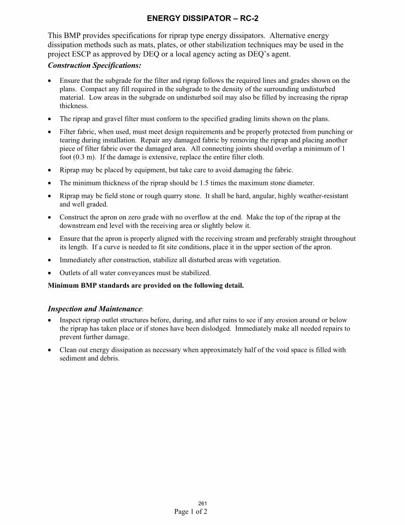
This BMP provides specifications for riprap type energy dissipators. Alternative energy dissipation methods such as mats, plates, or other stabilization techniques may be used in the project ESCP as approved by DEQ or a local agency acting as DEQ’s agent. Construction Specifications:
� Ensure that the subgrade for the filter and riprap follows the required lines and grades shown on the plans. Compact any fill required in the subgrade to the density of the surrounding undisturbed material. Low areas in the subgrade on undisturbed soil may also be filled by increasing the riprap thickness.
� The riprap and gravel filter must conform to the specified grading limits shown on the plans.
� Filter fabric, when used, must meet design requirements and be properly protected from punching or tearing during installation. Repair any damaged fabric by removing the riprap and placing another piece of filter fabric over the damaged area. All connecting joints should overlap a minimum of 1 foot (0.3 m). If the damage is extensive, replace the entire filter cloth.
� Riprap may be placed by equipment, but take care to avoid damaging the fabric.
� The minimum thickness of the riprap should be 1.5 times the maximum stone diameter.
� Riprap may be field stone or rough quarry stone. It shall be hard, angular, highly weather-resistant and well graded.
� Construct the apron on zero grade with no overflow at the end. Make the top of the riprap at the downstream end level with the receiving area or slightly below it.
� Ensure that the apron is properly aligned with the receiving stream and preferably straight throughout its length. If a curve is needed to fit site conditions, place it in the upper section of the apron.
� Immediately after construction, stabilize all disturbed areas with vegetation.
� Outlets of all water conveyances must be stabilized.
Minimum BMP standards are provided on the following detail.
Inspection and Maintenance:
� Inspect riprap outlet structures before, during, and after rains to see if any erosion around or below the riprap has taken place or if stones have been dislodged. Immediately make all needed repairs to prevent further damage.
� Clean out energy dissipation as necessary when approximately half of the void space is filled with sediment and debris.
261

ENERGY DISSIPATOR – RC-2
Page 2 of 2262

DIVERSION OF RUN-ON – RC-3
Page 1 of 2
Diversion consists of measures that intercept, divert and convey surface run-on, generally sheet flow, to prevent erosion and transport of pollutants through and from the site.
Construction Specifications:
� Construct diversion channels consisting of drainage swales; earth dikes; or other means such as sand bag barriers to intercept and divert run-on to avoid sheet flow over sloped surfaces and work areas (See SC-2 “Sand Bag Barrier”).
� Construct diversion structure to adequately convey storm flows based on careful evaluation of the risks due to erosion of the measure, soil types, over topping, flow backups, washout, and drainage flow patterns for each project site.
� Use other soil stabilization and sediment controls, such as check dams, plastics, and blankets, as necessary to prevent scour and erosion in newly graded dikes, swales and ditches.
� Correctly size and locate earth dikes, drainage swales and lined ditches. Excessively steep, unlined dikes and swales are themselves subject to erosion and gully formation.
� Stabilize conveyances as necessary and use a lined ditch for high flow velocities. Refer to EC-10 entitled “Erosion Control Blankets and Mats” or line with permanent, erosion-resistant material.
� Where appropriate, use natural streambed materials such as large cobbles and boulders for temporary embankment/slope protection, or other temporary soil stabilization methods.
� Compact any fills to prevent unequal settlement. � Divert runoff to an appropriate downstream location. � Use level spreaders (i.e., outlets for dikes and flow channels consisting of an excavated depression
constructed at zero grade across a slope), to convert concentrated runoff into sheetflow onto areas stabilized by existing vegetation.
� Do not divert runoff from the project to adjacent properties without permission. � When possible, install and utilize permanent dikes, swales and ditches early in the construction
process.� Convey collected run-on/concentrated flows down slopes in accordance with the RC-1 (“Slope
Drain”)� Provide stabilized outlets. Refer to RC-2 entitled “Energy Dissipator.” Minimum BMP standards are provided on the following detail.
Inspection and Maintenance:� Inspect temporary measures before, during and after rain events, and regularly. � Inspect ditches and berms for washouts. Replace lost riprap, damaged linings or soil stabilizers as
needed.� Inspect channel linings, embankments, and beds of ditches and berms for erosion and accumulation
of debris and sediment. Remove debris and sediment, and repair linings and embankments as needed or as directed by the engineer.
� Temporary conveyances shall be completely removed as soon as the surrounding drainage area has been stabilized, or at the completion of construction.
263

DIVERSION OF RUN-ON – RC-3
Page 2 of 2264

TEMPORARY DIVERSION DIKE RC-4
Page 1 of 3
Construction Specifications
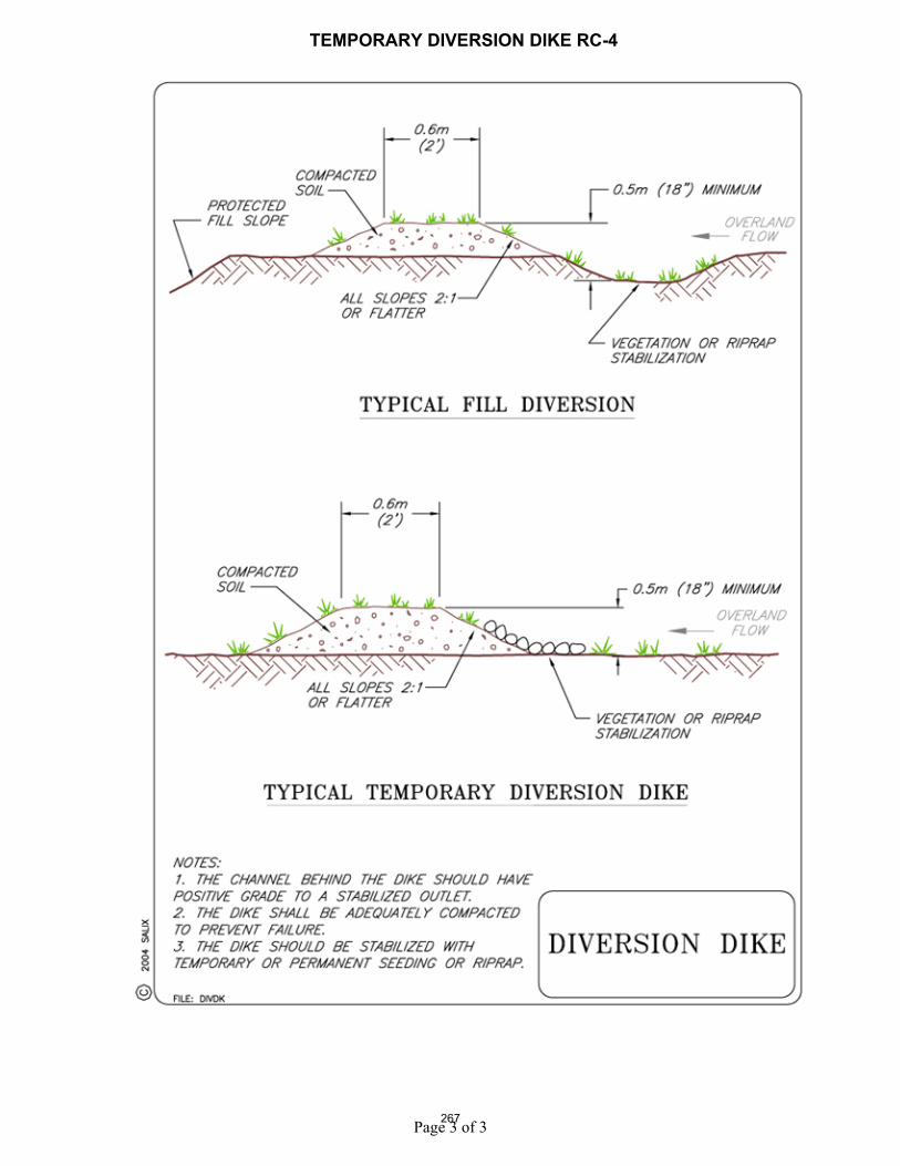
A Diversion Dike is a low berm (or ditch and berm combination) that is constructed along the crest or top of a streambank. The purpose of a diversion is to intercept and divert runoff away from the face of a steep slope or streambank. Diverted runoff should outlet onto a stabilized area, a prepared level spreader, or into a slope protection structure, e.g., a slope drain. Diversion dikes are constructed from compacted earthen fill and should be used on drainage areas of 5 acres (2 ha) or less. In addition to protecting the face of a streambank from overbank runoff, diversions may also improve general slope stability by preventing runoff from infiltrating into and saturating the face of the bank.
Conditions Where Practice Applies
Diversion Dikes should be used only on drainage areas of 5 acres (2 ha) or less.
Design Guidelines / Typical Drawings
Diversion dikes are constructed from compacted earthen fill to a height of 18 in (45 cm) with side slopes 1V:2H or flatter. Height is measured from the upslope toe to the top of the dike (see Figure 1).
Figure 1. Cross section and plan views of diversion dike
Figure 2. Diversion dike used in combination with a flexible slope drain
The dike should have a minimum top width of 2 ft (60 cm). A conceptual design for a diversion dike, either a berm only or a berm and ditch combination is shown in Figure 1. A shallow trench or swale to contain the diverted runoff is normally incorporated into the design. Soil from the ditch can be used to construct the berm, provided it has sufficient fines to hold a 1V:2H side slope and be relatively impermeable when compacted. The swale or drainage ditch must have positive drainage to an outlet. Vegetative or mechanical stabilization may be required where grades are excessive.
Materials and Equipment
Construction of a low dike requires soil with sufficient fines to hold a 1V:2H side slope and to be relatively impermeable when compacted. The dike can be constructed by hand or with the aid of a backhoe or front-end loader.
Construction / Installation � If overbank runoff is a problem, construction of a diversion dike or interceptor should precede
other bank stabilization treatments. � The height of the dike should be kept under 18 in (45 cm) so as not to interfere with bank access. � Use of a ditch and bank combination allows more efficient capture and diversion of runoff.
265

TEMPORARY DIVERSION DIKE RC-4
Page 2 of 3
� In addition, the soil excavated from the ditch can be used to construct the dike. Down drains or slope drains should be inserted through the dike periodically to convey the collected runoff to the stream below.
� Alternatively, the ditch should be constructed with sufficient positive grade to some other type of outlet.
Inspection and Maintenance
The dike or berm should be inspected to check that it has not been breached. Repair as needed. The ditch or swale behind the dike should also be checked for accumulation of sediment and debris. Excessive sediment accumulations should be removed.
Common Reasons / Circumstances for Failure
The most common reasons for failure are:
1. Overtopping and/or breaching of the dike or berm, 2. Excessive sediment accumulation in the ditch or swale behind the berm, and 3. Inadequate or insufficient outlet capacity of any appurtenant drop inlet and/or slope drains.
266
TEMPORARY DIVERSION DIKE RC-4
Page 3 of 3 267

GRASS-LINED CHANNEL (TURF REINFORCEMENT MATS) RC-5
Page 1 of 6
Construction Specifications Turf Reinforcement Mats (TRMs) are similar to Erosion Control Blankets, but they usually are intended for lining channels. They are composed of ultraviolet (UV) stabilized polymeric fibers, filaments, nettings and/or wire mesh, integrating together to form a three-dimensional matrix ¼ to ¾ in (5 to 20 mm) thick. The types of polymer include polypropylene, polyethylene, polyamides, and polyvinyl chloride. Often TRMs are combined with organic material such as coir to aide vegetation establishment and provide the initial temporary erosion control necessary to resist the forces of running water until the vegetation can become established. Typical vegetation includes grasses that can withstand inundation.
Conditions Where Practice Applies TRMs are designed to provide protection to resist channel and streambank erosion, and are useful when underlying soil boundaries may subside or shift slightly after installation.
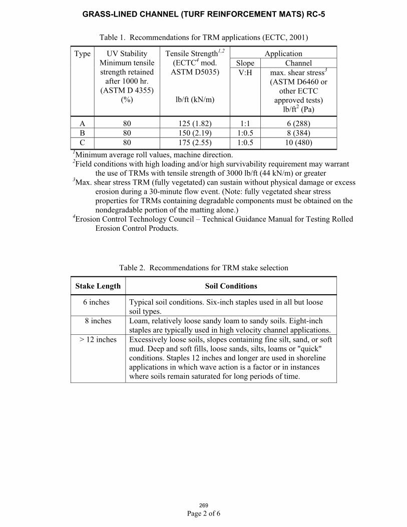
Design Specifications / Typical Drawings There are three types of TRMs, and their application depends on the site condition, as shown in Table 1.
TRMs can be installed after applying seed to the prepared soil surface or deployed first, and then seeded following infilling with soil. The former method allows the roots and shoots to grow through and interlock with the geosynthetic matrix, as shown in the second figure above. The channel or bank surface requires careful preparation, must be uniform and relatively free of rocks, stumps, clods etc, to ensure that there is complete contact between the TRM and the soil surface.
The number of anchoring stakes or staples per ft (or per m) is site and product specific, and should be determined according to the manufacturer’s specifications. See Table 2 for stake sizing recommendations. Live willow stakes may be substituted for metal or wooden anchoring stakes, although it should be noted that willows could shade out turf grass. Willow wattles or fascines may be used to anchor the mats into the slots.
268
GRASS-LINED CHANNEL (TURF REINFORCEMENT MATS) RC-5
Page 2 of 6
Table 1. Recommendations for TRM applications (ECTC, 2001)
Application Slope Channel
Type UV Stability Minimum tensile strength retained
after 1000 hr. (ASTM D 4355)
(%)
Tensile Strength1,2
(ECTC4 mod. ASTM D5035)
lb/ft (kN/m)
V:H max. shear stress3
(ASTM D6460 or other ECTC
approved tests) lb/ft2 (Pa)
A 80 125 (1.82) 1:1 6 (288) B 80 150 (2.19) 1:0.5 8 (384) C 80 175 (2.55) 1:0.5 10 (480)
1Minimum average roll values, machine direction. 2Field conditions with high loading and/or high survivability requirement may warrant
the use of TRMs with tensile strength of 3000 lb/ft (44 kN/m) or greater 3Max. shear stress TRM (fully vegetated) can sustain without physical damage or excess
erosion during a 30-minute flow event. (Note: fully vegetated shear stress properties for TRMs containing degradable components must be obtained on the nondegradable portion of the matting alone.)
4Erosion Control Technology Council – Technical Guidance Manual for Testing Rolled Erosion Control Products.
Table 2. Recommendations for TRM stake selection
Stake Length Soil Conditions
6 inches Typical soil conditions. Six-inch staples used in all but loose soil types.
8 inches Loam, relatively loose sandy loam to sandy soils. Eight-inch staples are typically used in high velocity channel applications.
> 12 inches Excessively loose soils, slopes containing fine silt, sand, or soft mud. Deep and soft fills, loose sands, silts, loams or "quick" conditions. Staples 12 inches and longer are used in shoreline applications in which wave action is a factor or in instances where soils remain saturated for long periods of time.
269

GRASS-LINED CHANNEL (TURF REINFORCEMENT MATS) RC-5
Page 3 of 6 270

GRASS-LINED CHANNEL (TURF REINFORCEMENT MATS) RC-5
Page 4 of 6 271

GRASS-LINED CHANNEL (TURF REINFORCEMENT MATS) RC-5
Page 5 of 6
Materials and Equipment TRMs may be installed either with hand labor or equipment; the main tools or equipment required consist of hammers, stapling devices, and shovels or equipment for trenching.
Construction / Installation TRMs (in channels) typically require very special installation and construction techniques.
Site Preparation The site should be fine graded to a smooth profile and relatively free from all weeds, clods, stones, roots, sticks, rills, gullies, crusting and caking.
Fill any voids and make sure that the channel is compacted properly.
SeedingSeed the area to be vegetated with a seed mix adapted to the local geographical area and soil conditions.
Choosing the appropriate seed mix will ensure optimum germination, root system development, vegetation density, and long term functionality. The types of seeds planted above the anticipated water line may differ from those below the anticipated water line.
If the prepared seed bed becomes crusted or eroded, or if ruts or depressions exist for any reason, prior to RECP installation the contractor should rework the soil until it is smooth and re-seed reworked areas.
TRM Installation in Channel Bottom TRMs should always be unrolled in the direction of water flow.
First, install the TRM in the channel bottom. Try to minimize the number of seams that are placed on the bottom of the channel, as these are sites of weakness. Do not put seams in the center of the channel bottom or in areas of concentrated water flow. When installing two TRMs side by side in a waterway, the center of the TRM should be centered in the area of concentrated water flow. Install adjoining TRMs away from the center of the channel bottom. Follow the manufacturer’s recommendations for overlapping the TRM; generally the overlap will be 50 to 100 mm (2 to 4 in).
Secure the TRM at the beginning of the channel with a 150 mm x 150 mm (6” x 6”) check slot dug perpendicular to the direction of water flow across the entire width of the channel.
Lay the TRM in the check slot with 750 mm (30 in) extending upstream of the check slot. Stake or staple the TRM in the check slot on 300 mm (12 in) centers.
Backfill the anchor trench and compact the soil. Place seed over the compacted soil if necessary.
Cover the compacted soil with the remaining 300 mm (12 in) of the terminal end of the TRM. Staple or stake the terminal end of the TRM down slope of the anchor trench on 300 mm (12 in) centers.
Check Slots “Check slots” (cutoff trenches) must be provided every 7.5 to 15 m (25-50 ft) to ensure water moving under the TRM is forced back to the surface. Longitudinal check slots are required to ensure off site “side flows” do not get under the TRM. Similarly, beginning and terminal check slots are critical.
Check slots can be installed in one of two ways, depending upon the Engineers discretion and/or the manufacturer’s recommendations.
One type of check slot is constructed by installing a double row of staples or stakes staggered and spaced 100 mm (4 in) apart.
272

GRASS-LINED CHANNEL (TURF REINFORCEMENT MATS) RC-5
Page 6 of 6
The second option is to install a check slot 150 mm (6 in) wide by 150 mm (6 in) deep, and secure the TRM in the upstream side of the check slot with staples or stakes on 300 mm (12 in) centers.
Flip the TRM roll on the upstream edge. Back fill the check slot and compact the soil. Continue rolling the TRM downstream over the completed check slot.
Installation on Side Slopes As the TRM is installed from the channel bottom up the slope, a shingle-type installation is recommended with the up-slope TRM overlapping the lower TRM approximately 50 to 100 mm (2 to 4 in).
Anchor the TRMs with a minimum of one staple every 60 mm (24 in) across the width and one staple every 90 mm (36 in) down the length.
If the TRM needs to be spliced, “shingle” it as discussed above, with a 100 mm (4 in) overlap. Use a staple check slot to secure the overlap.
Anchor the RECP placed at the top of the channel slope in the same manner as described in the slope section.
Terminal End Secure the TRM at the terminal end of the channel with a check slot similar to the one made at the beginning of the channel.
Alternative Channel Installation Method Another installation method for TRMs is to install them vertically and approximately 1 m (3 ft) onto the flat of the channel bottom. Construct a check slot in areas of concentrated water flow. Use a 50 to 100 mm (2 to 4 in) shingle-type overlap upstream to downstream.
Inspection and Maintenance Basic monitoring consists of visual inspections to determine mat integrity and attachment performance. Rill development beneath the mat or edge lifting are evidence of inadequate attachment. Additional staking and trenching can be employed to correct defects. Recently placed mats may be replaced, but once vegetation becomes established, replacement is not a reasonable option.
Common Reasons / Circumstances for Failure Critical points in conveyance system applications where mats can lose support include points of overlap between mats, projected water surface boundaries and channel bottoms.
Coir TRM channel installation, Guadalupe River, San Jose CA., October 2003
Same site during first large winter storms, winter 2004
273

TRENCH DRAIN RC-6
Page 1 of 3
Construction Specifications
A drainage trench is excavated parallel to and just behind the crest of a streambank. Ideally, the bottom of the trench should be keyed into an impermeable layer in the slope. The trench should be backfilled with a coarse graded aggregate that meets filtration criteria; i.e., it should allow unimpeded flow of groundwater while excluding fines from the seepage water. Alternatively, the trench can first be lined with a filter fabric (geotextile) that meets the filtration requirements and then be backfilled with a coarse aggregate. The purpose of the trench is to intercept and divert shallow seepage away from the face of the streambank. Note that trench drains must connect to a surface discharge pipe or otherwise may be classified as a Class V Underground Injection (UIC) well.
Conditions Where Practice Applies
Should be considered when shallow, water bearing strata conduct groundwater that emerges (daylights) at the streambank. A good example would be relatively permeable surface strata or water bearing sands up to 10 ft (3 m) thick, e.g., outwash sand or coarse alluvium, overlying relatively impermeable silty clay deposits, e.g., clay till or fine alluvium. This is a fairly common stratigraphic sequence in glaciated terrain and alluvial valleys.
Design Guidelines/ Typical Drawings
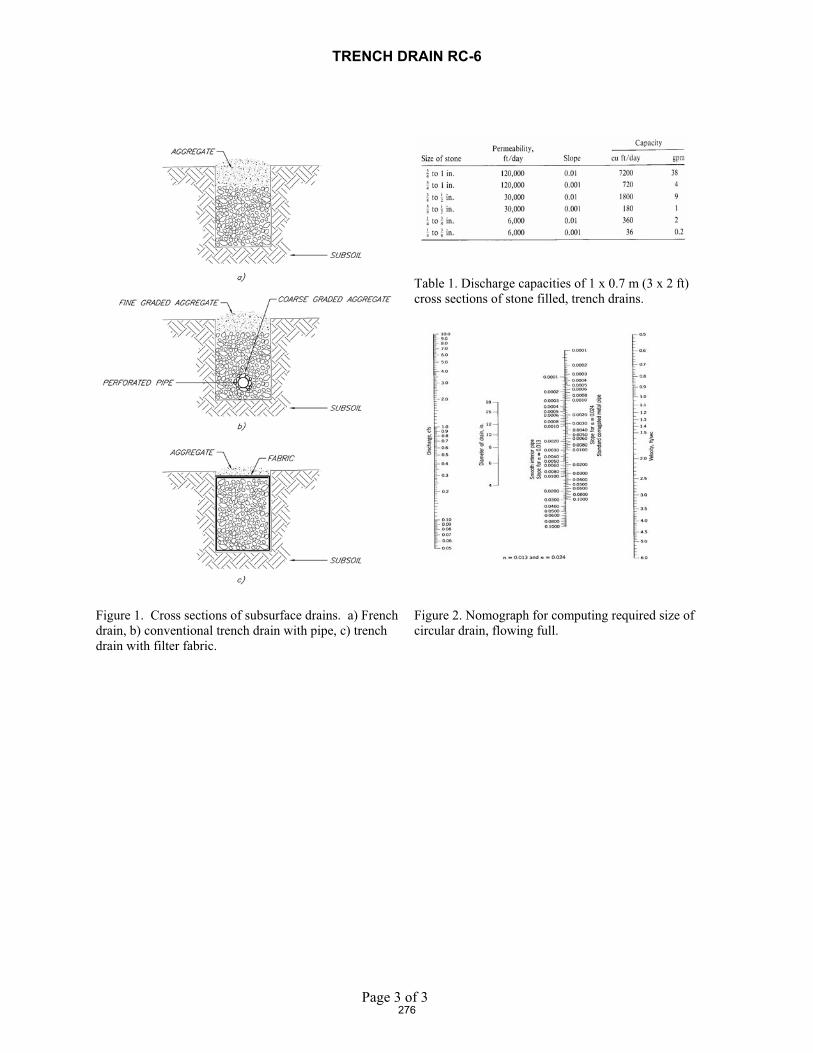
Trench Drains constructed without a pipe at the bottom are commonly known as French Drains (see Figure 1a). An efficient, well-constructed Trench Drain requires the use of perforated, jointed, slotted, or porous pipe placed near the bottom of a trench (see Figure 1b) that is surrounded with pea gravel or selected pervious filter aggregate. When a drain is excavated in erodible materials, synthetic filter fabrics (geotextiles) should be used (see Figure 1c) to line the sides and bottom of the trench to prevent soil fines from entering the coarse backfill in the drain. The main backfill should be specially selected pervious filter aggregate designed to allow unrestricted flow of water to the pipes.
Most drains should be equipped with pipes because gravel or rock-filled trenches have limited discharge capabilities even when clean aggregates are used. The discharge capabilities of drainage trenches backfilled with clean stone or coarse gravel, as estimated by Darcy's law, are given in Table 1. The required diameters of corrugated metal, concrete, and polymeric (smooth) drain pipes for a wide range of discharge quantities can be determined from the nomograph in Figure 2.
� The location of perforations and open joints in pipes should always be placed to allow unobstructed flow to pipes.
� If a drainage pipe is completely surrounded with specially selected coarse filter aggregate (refer to Figure 1b), perforations can completely surround the pipe.
Unjointed sections of pipe should be used to convey water across areas where the discharge of water into the soil from drains must be prevented. The same injunction holds for the final discharge of collected drain water, viz., it must not be allowed to discharge on to a slope and instead must be conducted safely down a slope using a chute or slope drain.
274

TRENCH DRAIN RC-6
Page 2 of 3
Materials and Equipment
Suitable drainage rock or gravel in addition to a perforated polymeric pipe. A small backhoe is required for excavating and backfilling the trench. A geotextile filter fabric will be required if the trench is to be lined.
Construction / Installation � Maximum trench depths are restricted to the reach of a backhoe/excavator or approximately 2 to
2.7 m (6 to 8 ft). � Trench widths are also determined by the width of the excavator bucket, which can range from
0.3 to 0.6 m (12 to 24 in). � The water transmission characteristics of the drainage trench can be improved by placing a
perforated or slotted drainage pipe on a slight grade at the bottom. � The discharge from a trench drain should be conveyed in a safe, non eroding manner down the
slope directly to the stream.
Inspection and Maintenance
Subsurface drains, including trench drains, are difficult to access and inspect once installed. A possible way to monitor the performance of a trench drain is to check the outflow from the pipe at the bottom of the interceptor trench. If there is steady shallow seepage towards a streambank, this exit pipe should flow continuously. The effectiveness of a trench drain for intercepting shallow seepage can be monitored indirectly by examining for signs of seepage and/or slumping/sliding at the bank face.
Common Reasons / Circumstances for Failure The limitations of trench drains cited previously are the most common reasons for failure. Failure to excavate the trench deep enough to reach the impermeable base of a perched groundwater system may let ground water pass under the trench. Loss of drainage capacity from clogging of a drain can lead to the saturation and buildup of pore pressure in the streambank itself. Either of these conditions can lead to mass stability failure of a streambank or seepage induced erosion of the bank face.
275
TRENCH DRAIN RC-6
Page 3 of 3
Table 1. Discharge capacities of 1 x 0.7 m (3 x 2 ft) cross sections of stone filled, trench drains.
Figure 1. Cross sections of subsurface drains. a) French drain, b) conventional trench drain with pipe, c) trench drain with filter fabric.
Figure 2. Nomograph for computing required size of circular drain, flowing full.
276

DROP INLET RC-7
Page 1 of 4
Construction Specifications
Concentrated overbank runoff can be a major cause of erosion, especially along deeply incised channels. Runoff passing over the top of banks frequently triggers gully development and expansion, and water that is ponded at the top of high, steep banks, and infiltrates or seeps into the ground behind the slope face is often a major factor in erosion by piping or slope failure from the development of high pore water or seepage pressures. The gully erosion and downcutting can be addressed using a drop inlet, which is a water control structure that consists of an L-shaped corrugated pipe passing through an earthen embankment placed at the downstream end of the gully.
Conditions Where Practice Applies
Used where large amounts of surface runoff flow across a steep high, streambank along an existing tributary gully or small ravine. Small amounts of overbank runoff flowing across a relatively intact or non-incised bank crest are best handled with a diversion dike and slope drains.
Design Guidelines / Typical Drawings
The following criteria are based on practices employed by the U.S. Army Corps of Engineers and the Natural Resources Conservation Service in the Southeast USA.
� Drop pipe structures are generally placed in gullies deeper than 10ft (3 m), and embankments are typically 15 to 20 ft (4.5 to 6 m) high.
� Minimum safety factors for embankments are 1.3, dictating side slopes of 1:2 to 1:3 (V:H).
� Pipes are sized to convey the 2- to 10-year event based on standard SCS runoff curve number computations, and an emergency spillway is provided to convey flows larger than the design discharge.
� Design discharges are typically less than 200 cfs (5.7 m3/s), and the vertical distance from the inlet weir crest to the outlet pipe invert is less than 30 ft (9 m). Pipe diameter and length are used to compute head-discharge relations, and pipe diameter is adjusted to avoid orifice flow at discharges less than or equal to design flow.
Drop pipes may be designated non-storage structures, which are sized to pass the two- to five-year event, or as temporary storage structures, which are designed to impound run-off from the 25-year event. Water retention is governed by site factors (soils, topography, and water supply) and by the elevation of the inlet weir and emergency spillway.
If uncontrolled erosion occurs in the drainage area behind the slope crest, the runoff may carry large amounts of sediment. A drop inlet can convey this sediment-laden runoff directly into an adjoining stream. If erosion is extensive, the drain itself may clog and lose a significant portion of its capacity. In these cases, sediment should be prevented from entering the drop inlet by providing some type of filtering and/or inlet protection, either filter fabric, gravel & wire mesh, or block and gravel sediment barrier. A photograph of a trash rack used to prevent large debris from entering and clogging a drop pipe is shown in Figure 1.
277
DROP INLET RC-7
Page 2 of 4
� Pipe materials can be aluminized or galvanized polymer-coated metal or polymeric materials. Seepage through the earthen embankment is controlled with seepage collars for structures with conduits 4 ft (1.2 m) in diameter or smaller, and with annular filter drainage rings for larger conduits.
� Where the structure will impound water permanently, a filter drainage diaphragm is used. Concrete pads are provided at the top and bottom of the vertical pipe, and an anti-vortex baffle is placed in the inlet to maintain weir flow and avoid vibration during very large events (see Figure 2). Outlets are supported with grouted riprap and secured with screw anchors. In addition, stone erosion protection is provided at the outlet for structures larger than 4 ft (1.2 m) in diameter.
Materials and Equipment
Earthmoving equipment and standard erosion control measures are needed for construction of the embankment. A source of fill for the dam is needed, and pipes, trashracks, and stone for scour protection are essential materials. Pipe materials can be aluminized or galvanized polymer-coated metal or polymeric materials.
Common Reasons / Circumstances for Failure
� Clogging of the down-pipe can lead to possible overtopping of the containment embankment and erosion of the downstream face of the dam in the absence of a properly designed emergency spillway.
� Excessive sediment in the runoff can be conveyed to the stream channel below in the absence of suitable filtering at the inlet and/or a long enough residence time in the ponded area behind the embankment dike.
� Ponding of water atop a streambank can exacerbate piping and seepage related bank instability. This latter problem is minimized, however, if the embankment and pond are located at the downstream end of the gully and if pond water levels are maintained as low as possible.
Inspection and Maintenance
Clogging of the inlet can be prevented by periodic inspection of the entrance protection structure or trash rack (see Figure 1 and 2). If sediment in the pond behind the dam accumulates to the base of the pipe entrance, it may be necessary to raise the entrance elevation of the pipe. A gully treatment program in the upstream reaches of the gully or gully network can also be employed to reduce sediment loading.
278

DROP INLET RC-7
Page 3 of 4
Figure 1. Metal trash rack used to protect drop inlet
Figure 2. Drop inlet pipe with anti-vortex baffle and trash rack
279

DROP INLET RC-7
Page 4 of 4280

MINIMIZING TOTAL SUSPENDED SOLIDS (TSS) RC-8
Page 1 of 2
Construction Specifications Whatever technique you decide to implement, an important thing to remember is that dilution can sometimes be the solution. A probable “worst time” to release high TSS into a stream system might be when the stream is very low; summer low flow, for example. During these times, the flow may be low while the biological activity in the stream is very high. Conversely, the addition of high TSS or sediment during a big storm discharge might have a relatively low impact, because the stream is already turbid, and the stream energy is capable of transporting both suspended solids, and large quantities of bedload through the system. The optimum time to “pull” in-stream structures may be during the rising limb of a storm hydrograph. Techniques to Minimize Total Suspended Solids (TSS)PaddingPadding, usually manufactured from coir and or other natural fibers, that is laid in the stream below the work site may trap some solids that are deposited in the stream during construction. After work is done, the padding is removed from the stream, and placed on the bank to assist in revegetation.Clean, washed gravelClean, washed gravel can be placed on the stream bottom both during and after construction to minimize re-mobilizing the “fines”. Clean gravel or spawning gravel can often be specified to mitigate or enhance the existing substrate. Therefore, gravel “injection” can minimize TSS during construction while providing environmental and habitat enhancements with long-term benefits.Excavation using a large bucket Each time a bucket of soil is excavated or placed in the stream, a portion is of the soil is suspended. The resulting amount of sediment suspended increases proportionally to the number of scoops rather than the total of excavated soil. Therefore, using a large excavator bucket instead of a small one will reduce the total amount of soil that is suspended and available to wash downstream. Each time a bucket of soil is placed in the stream, a portion is suspended.Approximately the same amount is suspended whether a small amount of soil is placed in the stream, or a large amount. Use of dozer for backfillingUsing a dozer for backfilling instead of a backhoe follows the same principles – the fewer times soil is deposited in the stream, the less soil will be suspended.Partial dewatering with a pumpPartially dewatering a stream with a pump reduces the amount of water, and thus the amount of water that can suspend sediment. How to know if you have high TSS:Some commonly accepted standards for high TSS are:
� 50 mg/l or � 10 mg/l above background TSS or, � 10% above background TSS.
These standards are very stringent, and are very difficult to achieve in many situations. The background + 10 % (mg/l) is probably the most realistic and reasonable standard for protecting the aquatic resources, while allowing a restoration project to be implemented. Check with local ordinances for standards.
281

MINIMIZING TOTAL SUSPENDED SOLIDS (TSS) RC-8
Page 2 of 2
Inspection and Maintenance
� Inspect the stability and performance of all erosion and sediment control measures during construction.
� Monitor TSS levels before, during and after construction.
282

IN-STREAM DIVERSION TECHNIQUES RC-9
Page 1 of 2
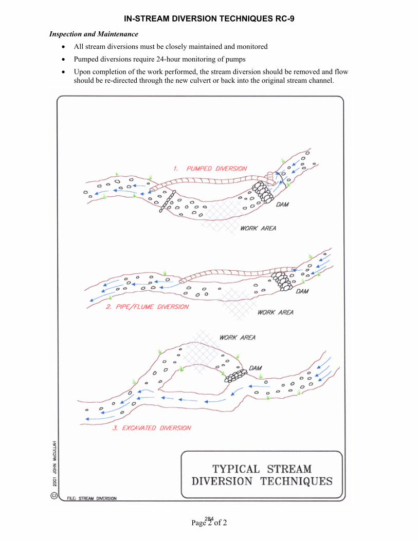
Construction SpecificationsA stream diversion is a temporary bypass through a pipe, flume, or excavated channel that carries water flow around work areas. Stream diversion is commonly used during culvert installation or replacement. Where possible, a stream diversion should be the first choice to control erosion and sediment during the construction of culverts or other in-stream structures. During construction in a watercourse, particularly culvert installation and repair, these temporary water bypass structures are an effective sediment and erosion control technique. Check with local, state and federal regulatory authorities for permitting and design requirements. Design ConsiderationsThe selection of which stream diversion technique to use will depend upon the type of work involved, physical characteristics of the site, and the volume of water flowing through the project. Advantages of a pumped diversion include:
� Downstream sediment transport can almost be eliminated
� De-watering of the work area is possible
� Pipes can be moved about to allow construction operations
� The dams can serve as temporary access.
� Increased flows can be managed by adding more pumping capacity. Some disadvantages of a pumped diversion are:
� Flow volume is limited by pump capacity
� Requires 24-hour monitoring of pumps
� Sudden rain could overtop dams
� Minor in-stream disturbance to install and remove dams Advantages of excavated channels and flumes are:
� Isolates work from water flow and allows dewatering
� Can handle larger flows than pumps Disadvantages of excavated channels and flumes are:
� Bypass channel or flume must be sized to handle flows, including possible floods
� Channels must be protected from erosion
� Flow diversion and then re-direction with small dams causes in-stream disturbance and sediment
Stream diversions should not be used:
� Without identifying potential impacts to the stream channel
� In or adjacent to water bodies until all necessary permits have been obtained
Installation � The pumped diversion is suitable for intermittent and low flow streams that can be pumped.
Pump capacity must be sufficient for design flow. The upper limit is about 10ft3/sec (0.28 m3/sec), the capacity of two 8 inch (20 cm) pumps.
� A temporary dam is constructed upstream and downstream of the work area and water is pumped through the construction project in pipes. Dam materials should be selected to be erosion resistant, such as steel plate, sheetpile, sandbags, continuous berms, inflatable water bladders, etc.
� A temporary bypass channel can also be constructed by excavating a temporary channel or passing the flow through a heavy pipe (called a “flume”), and excavating a trench under it. Typical stream sizes are less than 20 ft (6 m) wide and less than 100 ft3/sec (2.8 m3/sec).
283
IN-STREAM DIVERSION TECHNIQUES RC-9
Page 2 of 2
Inspection and Maintenance
� All stream diversions must be closely maintained and monitored
� Pumped diversions require 24-hour monitoring of pumps
� Upon completion of the work performed, the stream diversion should be removed and flow should be re-directed through the new culvert or back into the original stream channel.
284

INSTREAM ISOLATION TECHNIQUES RC-10
Page 1 of 5
Portable dams installed in Santa Cruz Ca. and in Alberta Canada.
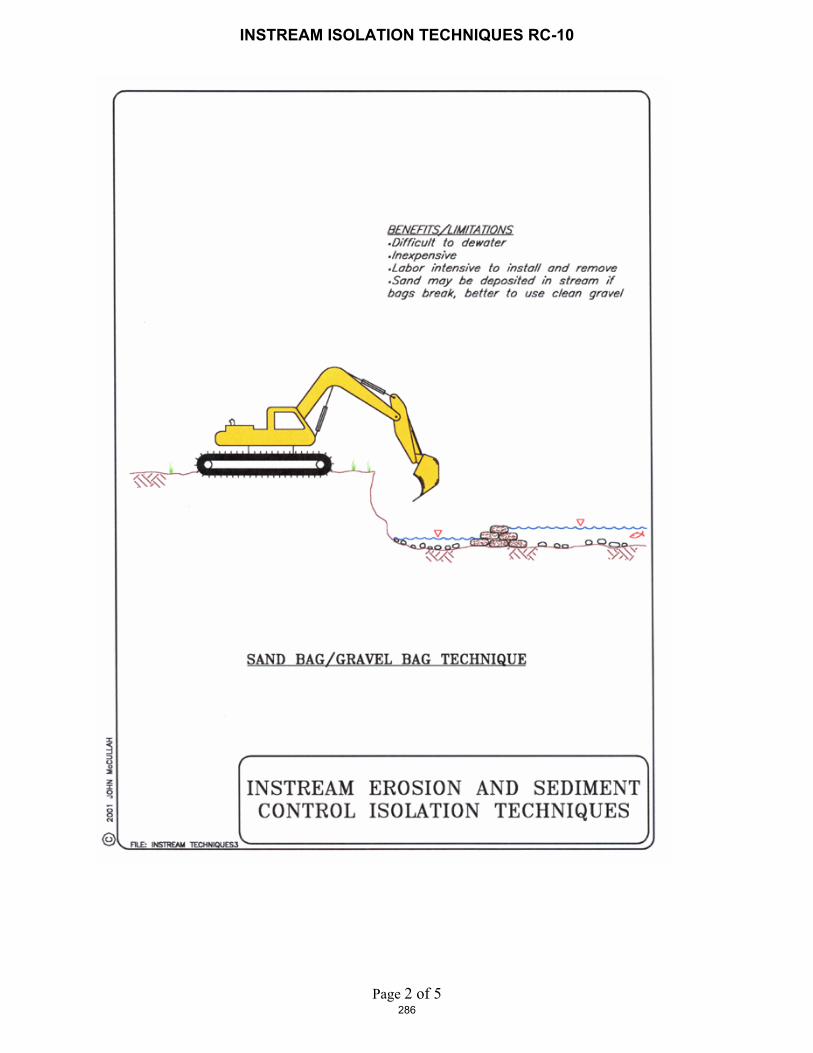
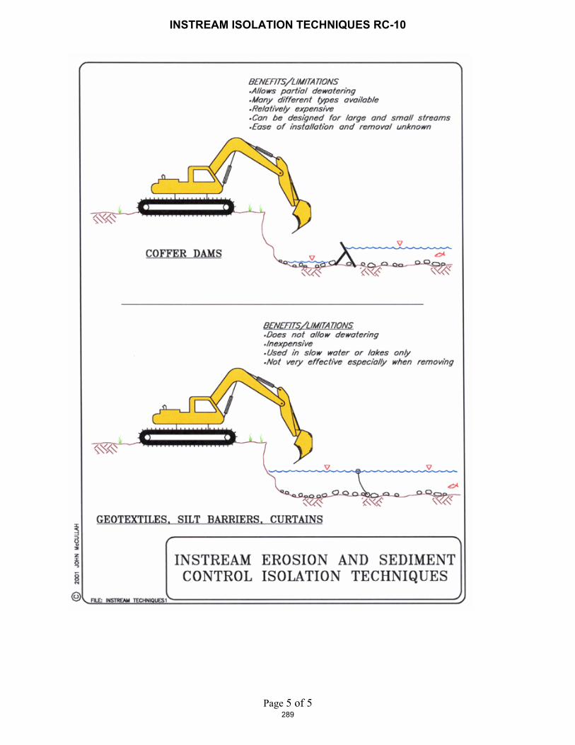
Construction Specifications An instream isolation technique is a temporary structure built into a waterway to enclose a construction area and reduce sediment pollution from construction work in or adjacent to water. The structures may be made of rock, sand bags, wood or water-filled geotextiles (aqua barriers). During construction in a watercourse, these structures are designed to reduce turbidity and sediment discharge, allowing contractors to follow clean water regulations.
Design Considerations Isolation structures may be used in construction activities such as streambank stabilization, culvert installation, bridges, piers or abutments. It may be used in combination with other methods such as clean water bypasses and/or pumps. This technique should not be used:
� If there is insufficient streamflow to support aquatic species.
� In deep water unless designed or reviewed by and engineer.
� To completely dam streamflows.
Installation When used in watercourses or streams, cofferdams must be used in accordance with permit requirements. Materials for cofferdams should be selected based on ease of maintenance and complete removal following construction activities.
Inspection and Maintenance� During construction, inspect daily.
� Schedule additional inspections during storm events.
� Immediately repair any gaps, holes or scour.
� Upon construction completion, the structure is removed.
� Remove sediment buildup.
� Remove structure. Recycle or re-use if applicable.
� Revegetate areas disturbed by cofferdam removal if applicable.
285
INSTREAM ISOLATION TECHNIQUES RC-10
Page 2 of 5286

INSTREAM ISOLATION TECHNIQUES RC-10
Page 3 of 5287

INSTREAM ISOLATION TECHNIQUES RC-10
Page 4 of 5288
INSTREAM ISOLATION TECHNIQUES RC-10
Page 5 of 5289
CHECK DAMS –RC-11
Page 1 of 3
Construction Specifications:
� Check dams shall be placed at a distance and height to allow small pools to form behind them. The maximum spacing between the dams shall be such that the toe of the upstream dam is at the same elevation as the top of the downstream dam.
� High flows (typically a 2-year storm or larger) shall safely flow over the check dam without an increase in upstream flooding or damage to the check dam.
� Where grass is used to line ditches, check dams shall be removed when grass has matured sufficiently to protect the ditch or swale.
� Construct rock dams such that structures are not damaged by vehicles and do not impede travel ways. � Rock dams shall be constructed of 2 to 15-inch rock. � Keep the center rock (spillway) section at least 6 inches lower than the outer edges. � Extend the abutments 18" into the channel bank. � Only gravel bags may be used as check dams with the following specifications:
Materialso Bag Material: Bags shall be either polypropylene, polyethylene or polyamide woven fabric,
minimum unit weight four ounces per square yard (135 g/m2), mullen burst strength exceeding 300 psi (2,070 kPa) in conformance with the requirements in ASTM designation D3786, and ultraviolet stability exceeding 70% in conformance with the requirements in ASTM designation D4355.
o Bag Size: Each gravel-filled bag shall have a length of 18 in (450 mm), width of 12 in (300 mm), thickness of 3 in (75 mm), and mass of approximately 33 lb (15 kg). Bag dimensions are nominal, and may vary based on locally available materials. Alternative bag sizes shall be submitted to the engineer for approval prior to deployment.
o Fill Material: Fill material shall be between 10 mm and 20 mm (0.4 and 0.8 inch) in diameter, and shall be clean and free from clay balls, organic matter, and other deleterious materials. The opening of gravel-filled bags shall be secured such that gravel does not escape. Gravel-filled bags shall be between 28 and 48 lb (13 kg and 22 kg) in mass. Fill material is subject to approval by the engineer.
Installationo Install along a level contour. o Tightly abut bags and stack gravel bags using a pyramid approach. Gravel bags shall not be
stacked any higher than 3.2 ft (1 meter). o Upper rows of gravel bags shall overlap joints in lower rows.
o Local and state requirements shall be met concerning fencing and signs warning the public of hazards of soft sediment and floodwater.
Minimum BMP standards are provided on the following illustrations.
Inspection and Maintenance:� Inspect check dams before, during, and after each rainfall event. Repair damage as needed. � Remove sediment when depth reaches one-third of the check dam height. � Remove accumulated sediment prior to permanent seeding or soil stabilization. � Remove check dam and accumulated sediment when check dams are no longer needed. � Removed sediment shall be incorporated in the project or disposed of properly.
290

CHECK DAMS –RC-11
Page 2 of 3
NOTE:KEY STONE INTO THE CHANNEL BANKS AND EXTEND CHECK DAM A MINIMUM OF 18” TO PREVENT FLOW AROUND DAM.
291

CHECK DAMS –RC-11
Page 3 of 3292