Working Drawings - The House Designers · loading code and as 1684.2 - 2010 - residential...
12
NOTES: Images Are Diagramatic Only Refer To Elevations For Details xxx xxx Issue Date Description Proposed New Residence For: Proposed New Residence For: Working Drawings Cover Sheet Electrical Plan Slab Layout 4 3 2 Sections / Details 1 Site Plan Floor Plan - Upper Legends / Notes Bracing Plan 5 6 7 8 9 10 Elevations 1 of 2 Elevations 2 of 2 1:200 @ A3 1:100 @ A3 1:100 @ A3 1:100 @ A3 as per dwg. 1:100 @ A3 1:100 @ A3 1:100 @ A3 N/A N/A 11 Landscaping Plan 1:200 @ A3 Floor Plan - Lower 1:100 @ A3 12 Example Working Drawings Sloping Site
Transcript of Working Drawings - The House Designers · loading code and as 1684.2 - 2010 - residential...

NOTES:Images Are Diagramatic OnlyRefer To Elevations For Details
xxx
xxx
Issue Date Description
Proposed New Residence For:Proposed New Residence For:
Working Drawings
Cover Sheet
Electrical Plan
Slab Layout
4
3
2
Sections / Details
1
Site Plan
Floor Plan - Upper
Legends / Notes
Bracing Plan
5
6
7
8
9
10
Elevations 1 of 2
Elevations 2 of 2
1:200 @ A3
1:100 @ A3
1:100 @ A3
1:100 @ A3
as per dwg.
1:100 @ A3
1:100 @ A3
1:100 @ A3
N/A
N/A
11
Landscaping Plan 1:200 @ A3
Floor Plan - Lower 1:100 @ A3
12
Example Working DrawingsSloping Site

Area Calculations
Living Lower:
Living Upper:
Garage:
Porch:
Alfresco:
Total:
3.98 sqm
201.91 sqm
36.08 sqm
12.31 sqm
119.98 sqm
29.56 sqm
Working Drawings
Legends / NotesDesign Name:
Title:
Checked By:
Drawing No: Scale:Client:
2 of
Outrigger 201
Job No:
Drawn By:
Issue:Plot Date: 6/07/2015
Designed By:xxx
xxx
12
MBOwner / s ..............................................................Date...................
Owner / s ..............................................................Date...................
Please Read CarefullyWe reserve the right to alter designs, colours andspecifications without notice. Whilst every care hasbeen taken in the preparation of this document, theparticulars contained herein are not to be constructedas any respresentation of fact. All information provided tous is from reputable sources and no responsibility isaccepted by the vendor, it's servants or agents for any errorsor omissions. All interested parties should make their ownenquiries to satisfy themselves in relation to all matters.
© The House Designers. The copyright of these floor plans are owned by The House Designers. The floor plans may not be reproduced, copied or dealt with in any manner which infringes the exclusive rights of The House Designers. Upon receiving payment in full, the client receives permission for single use.
MB
This plan certified correct is the one referred to in the contract &specifications and I understand change hereafter may not bepossible. These plans supercede all other previous plans or sketches.
MB
T: (07) 5602 6177 0408 701 623W: www.thehousedesigners.com.auA: 1 / 7 Straithaird Road Bundall QLD 4217P: Po box 3282 Nerang DC QLD 4210QBCC: 1274038
Articulation Joints
(a) Verticle articulations joints must be provided in unreinforced masonry walls except where the site soli classification is A or Sb) Articulation joints between masonry elements must have a width not less than 10 mm and be provided (see Figures 3.3.1.7
and 3.3.1.8)-(i) in straight, continuous walls having no openings, at not more than 6 m centres and not closer than the height of
the wall away from corners; and(ii) where the height of the wall changes by more than 20%, at the position of change in height; and(iii) where openings more than 900x900 mm occur, at not more than 5 m centres, and positioned in line with one edge
of the opening; and(iv) where walls change in thickness; and(v) at control or construction joints in footing slabs; and(vi) at junctions of walls constructed of different masonry materials; and(vii) at deep chases (rebates) for service pipes.
(c) For all articulation joints in cavity walls, extendable masonry anchors must be built in at every fourth course (see Figure3.3.1.9). For veneer construction the extendable ties may be omitted.
(d) For single leaf masonry walls stabilised by return walls, or engaged piers, any articulation joints must be within 300 mm ofthe vertical support (see Figures 3.3.1.3 and 3.3.1.4(b)).
(e) Where masonry is required to be waterproof all joints must be sealed with a flexible, compressible material (see Figure3.3.1.9).
(f) Articulation joints must not be constructed adjacent to arched openings.(g) Articulation joints must not be located in unreinforced masonry above garage door openings or the like unless the panel of
masonry is laterally supported with masonry ties or other suitable means.
To comply with BCA 3.12(unless otherwise stated)
AS PER ENERGY RATING ASSESSMENT CERTIFICATE
• Dishwasher provision under sink drainer including cold water connection & GPO
• Ventilation to internal wc / bath to be an exhaust fan in accordance with BCA F5.4 & AS - 1668.2
• O/head cupboards to 2250mm AFL with MDF bulkhead over
• All openings to have 2100mm AFL
• Robe fitout (1) shelf with hanging rail
• PVC Downpipes
• Lift off hinges to w/c, Ensuite, Bathroom
• Dimensions are to be verified prior to commencement of work
• Given dimensions are to have priority to scaled dimensions
• All stairs are to have 190mm maximum risers and 240mm minimum goings
• All wet areas to be in accordance with the current Building Code of Australia 3.8.1 & current AS.
• Floor wastes to wet areas
Denotes Smoke Detector
• Contractor to verify all boundary clearances & site set-out dimensions prior to commencement of construction
• Levels & contours are based on assumed datum. Prior to construction the relevant authority should be
contacted for possible minimum floor level requirements & flood information
• Retaining walls greater than 1m high (cut or fill) are required to be engineer designed & certified
• Batters to comply appropriate soil classification described in table 3.1.1.1. BCA Vol.2.
• Vehicular cross-over to be constructed as per local council requirements and/or approval
• Driveways, paths, porch, alfresco area finish as per specifications
• Scrape away vegetation & cut & fill to provide a level building platform
• Finish surface to be graded away from house at minimum of 1:20 for at least 1m
• Surface water to be channelled to council stormwater drainage system
• The driveway & pathways indicated on plan are suggested layouts
• All ground levels are approximate only
• All works to be constructed in accordance with the current Building Code of Australia,
the current Australian Standards and all relevant current trade & technical manuals
• Drainage to be in accordance with part 3 of the BCA. Point to meet local authority requirements
• All plumbing & draining is to comply with the standard sewerage by-laws & requirements of the local authority
• All downpipes to be installed in accordance the current Building Code of Australia 3.5.2.5,
each downpipe must not serve more than 12m of gutter length
• Stormwater system to local authority requirements ( owner / applicant / builder to ensure no storm water
runoff occurs onto adjoining properties, back onto any structures & no ponding under sub floor areas
• Stormwater approval for legal discharge to be obtained from local authority prior to work commencing.
Discharge is proposed to: kerb & channel, rubble pit to council requirements, inter allotment drainage,
storm water service main, canal or river.
Jam studs: Beside open. up to 1400mm wideBeside open. up to 2300mm wideBeside open. up to 3300mm wide
2 / 35 X 70 (MGP 12)3 / 35 X 70 (MGP 12)4 / 35 X 70 (MGP 12)
Note: all timber sizes are based on the current timber engineering code AS 1720.All member types are analyzed using limit state principles incorporatings thelatest timber technology available. All of the member types accessible usingtimber sizes meet the loading and serviceability criteria outlined in AS 1170.1 saaloading code and as 1684.2 - 2010 - residential timber-framed construction - part1 - design criteria. All timber framing to be in accordance with AS 1684.3-2010
Construction NotesThis building has been designed in accordance with the current building code ofaustralia, building act ammendment & australian standards
Footings
Slab Height
Termite Management
External Walls - Brick Veneer
To engineers design & detail
In accordance with BCA volume 2, 3.1.3 termite riskmanagement and A.S. 3660.1/1995
Internal Linings 10mm Plasterboard
6 mm Villaboard to all wet areas
10mm Plasterboard
4.5mm Hardiflex
Metal Fascia Fixed To Standard Rafter Bracket,Complete With Mitre Angles, Joining Sleeves Etc
Ceiling Linings
Soffit Linings
Window Flashing
Roofing Colorbond sheet, Pitch as specified on drawings
Ceiling Height
Joinery Level
As specified on drawings
Roof Bracing
Fascia
Downpipes
Guttering
Smoke Alarms To Be Hard Wire Installed In Accordance With Part 3.7.2 Of The B.C.A.
As specified on drawings
To engineers design & detail
230mm - 110mm Brickwork, 50mm Cavity, 70mm Timber Studs
General Notes
Energy Efficiency
Stormwater / Drainage Notes
Site Notes
ALL WORKS SHALL COMPLY WITH BUT NOT LIMITED TO THE BUILDINGCODE OF AUSTRALIAN AND THE CURRENT AUSTRALIAN STANDARDS
Timber Schedule
Wall Framing
Top Plate(Load Bearing)
Bottom Plate(Load Bearing)
Seasoned Pine
2 / 35 X 70 (MGP 12)
35 X 70 (MGP 12)
Bottom Plate(Non Load Bearing)
35 X 70 (MGP 10)
Studs(Load Bearing)
Studs(Non Load Bearing)
35 X 70 (MGP 12) @ 450 cts.
35 X 70 (MGP 10) @ 600 cts. (max. height 3000mm)
Nogging: 35 X 70 (MGP 10)
Bearers & joists
As specified by engineer designed & fixed in accordancewith manufacturer's specifications & tie down details
Prefabricated timber roof trusses @ specified 600 cts.Trusses to be engineer designed & fixed in accordance withmanufacturer's specifications & tie down details
Lintels & beams:
Roof framing:
As specified by engineer designed & fixed in accordancewith manufacturer's specifications & tie down details
BCA Building Code of AustraliaAS Australian StandardsDP DownpipeHWS Hot Water SystemSHS Steel PostSD Service DuctFW Floor WasteT.B.C To Be ConfirmedR.L Relative LevelAFL Above Floor LevelNGL Natural Ground LevelFGL Finished Ground LevelOHC Overhead CupboardUBO Under Bench OvenWO Wall Oven
Legend
DEVELOPMENT NEAR UNDERGROUND UTILITY SERVICES
For the purpose of this section of the table:
· An approval that has been granted to the development pursuant to Section 823 of theWater Act 2000 is deemed to satisfy the Performance Criteria of this section.4
· “Access Cover” means a removable cover to provide access for cleaning or inspection ofsewers, stormwater drains and water mains.
· “Associated Structure” includes a sewer or stormwater manhole, a water meter and a firehydrant.
· “Building” has the meaning defined in the Building Act 1975.· “Connection Point” has the meaning defined in the Standard Sewerage Law.· “Invert Level” means the bottom level of the inside of the pipe or drain.· “Manhole” means an access chamber being a below Ground Level structure, with a cover,
built in the line of a sewer or stormwater drain, through which a person may access thesewer or stormwater drain.
· “Sewer” includes sanitary drain jump-ups and capped slope junctions and manholes.· “Structure’ includes a masonry fence, deck, pergola, satellite dish, water storage tank and
a retaining wall (of greater than 1 metre in Height).· “Zone of Influence” means the area shown on the following diagram:
To All Windows. As per manufacturers details
Speed Brace. As per manufacturers details
Colorbond
PVC
WMS Washing Machine SpaceW.I.R Walk-in-RobeSGD Sliding Glass DoorSW Aluminum Sliding WindowDH Aluminum Double Hung WindowAW Aluminum Awning WindowLV Aluminum Louvre WindowFG Fixed GlassSL Side LightSHR ShowerTR Towel RailTRH Toilet Roll HolderVSD Vinyl Sliding DoorMSD Mirrored Sliding DoorCSD Cavity Sliding DoorRW Rainwater LineDW Dishwasher ProvisionMO Microwave Provision
N/A

Area Calculations
Living Lower:
Living Upper:
Garage:
Porch:
Alfresco:
Total:
3.98 sqm
201.91 sqm
36.08 sqm
12.31 sqm
119.98 sqm
29.56 sqm
Working Drawings
Site PlanDesign Name:
Title:
Checked By:
Drawing No: Scale:Client:
3 of
Outrigger 201
Job No:
Drawn By:
Issue:Plot Date: 6/07/2015
Designed By:xxx
xxx
12
MBOwner / s ..............................................................Date...................
Owner / s ..............................................................Date...................
Please Read CarefullyWe reserve the right to alter designs, colours andspecifications without notice. Whilst every care hasbeen taken in the preparation of this document, theparticulars contained herein are not to be constructedas any respresentation of fact. All information provided tous is from reputable sources and no responsibility isaccepted by the vendor, it's servants or agents for any errorsor omissions. All interested parties should make their ownenquiries to satisfy themselves in relation to all matters.
© The House Designers. The copyright of these floor plans are owned by The House Designers. The floor plans may not be reproduced, copied or dealt with in any manner which infringes the exclusive rights of The House Designers. Upon receiving payment in full, the client receives permission for single use.
MB
This plan certified correct is the one referred to in the contract &specifications and I understand change hereafter may not bepossible. These plans supercede all other previous plans or sketches.
MB
T: (07) 5602 6177 0408 701 623W: www.thehousedesigners.com.auA: 1 / 7 Straithaird Road Bundall QLD 4217P: Po box 3282 Nerang DC QLD 4210QBCC: 1274038
m/box
HW
S
1,77
0
1,50
0
2,55
0
3,559
3,850
4,300 16,045 2,955
2,06
010
,440
1,50
0
1.8m high fence & gate return1m back from front building line
tiered rock retaining wallmax height 1m
dismantle existing footpathreplace with coloured concrete
coloured concrete driveway finish
stormwater to legalpoint of discharge
stormwater to legalpoint of discharge
rock retaining wallmax height 1m
tiered rock retaining wallmax height 1m
denotes batter
McG
rego
rPl
ace
LOT 2406374 M2
gate
Lot 2407
Lot 2405
Lot 2408
Lot 2409
15.576
103°09'35"
23.3 167°09'55"
14.0257 °09'55"
30.127
7.00
6.50
6.75
7.00
7.758.008.25
8.508.75
347°09'55"
CON
C
TOP OF BANK
9.009.25
9.50
9.75
10.00
10.2510.50
10.75
11.0011.2511.50
12.50
11.5011.75
12.0012.25
SITE BENCH
MARK
NAIL IN
KERBRL6.81 (Arbitrary)
ELECTRICITY PILLAR ROO
FWATER IL6.85
FH
FIRE HYD
RANT
WM
WMOP
EPIL
ELP
LIGHT POLE
CPIT
COM
MU
NICATIO
NS PIT
OP
OP
OP
6.92
6.62
6.36
6.26
6.53
6.80
6.16
WATER M
ETERSL6.36
6.65
6.88
6.89
7.05 6.96
7.35
7.53
7.20
7.74
9.05
9.23
9.25
9.11
9.10
9.22
11.74
11.63
11.77
11.67
12.41
12.53
9.26
9.32
9.37
9.42
9.33
9.35
10.09 10.05
10.07
10.08
10.16
7.08
6.62
6.32
6.40
6.99
678
659
6.56
10.19
931
917
7.25
7.507.25
9.25
6.75
9.25
7.50
7.758.00
8.258.50
8.759.00
9.259.509.7510.00
10.2510.5010.75
11.0011.25
10.00
9.50
9.008.758.508.258.007.757.50
7.00
7.25
9.50
9.75
L
dp
dpdp
dp
RWRWRW
RW RW RW
S
S
S
S
S
S
cut fill
cut fill
1.8m high fence return1m back from front building line
rock retaining wallmax height 1m
FFL RL 7.810PAD RL 7.500
FFL RL 10.570PAD (FGL) 9.600 approx.
FGL 17.500
dp
Site Notes:
• length of all retaining walls t.b.c on site by supervisor• retaining walls higher than 1m in height to be engineered designed• retaining walls constructed from treated pine timber or rock as per plans• agriculture drainage systems to be used• retaining walls may change location at supervisor's discrection if required• fencing in accordance with developer covenants• landscaping in accordance with developer covenants• driveway gradient not to exceed 1:5• Batters to comply appropriate soil classification described in table 3.1.1.1.BCA Vol.2.• stormwater to legal point of dishcharge
direction of fall
RW Roof Water Line
Legend
timber retaining wall
rock retaining wall
1800mm hightimber fence
Proposed FGL RL
16.65NGL RL
16.65
Rendered Leterbox
R B
L
Real Property Description
Lot Number: 2406Registered Plan Number: SP 230012Parish: StapyltonCounty: StanleyLocal Authority: Ipswitch C.C
Site Area: 374M2
Site Coverage: 40%
8.3 m1.01 m
1:8
R.L 6.800n/aDistance
Grade 1:8Transitional
Grade
DistanceHeight GainFFLNGL (boundary)
Driveway Gradient
1:4 1:8n/a n/a
R.L 7.810
1500mm high timber toprail & posts with poolstyle infill fencing
G Single timber gate
Downpipe Location
Stormwater Line
S Sewer Line
Rubbish Bin Location
590X350 renderedbrick pierspainted horizontaltimber battens
HTB
Nor
thEast
Sout
hwest
1:200 @ A3

Area Calculations
Living Lower:
Living Upper:
Garage:
Porch:
Alfresco:
Total:
3.98 sqm
201.91 sqm
36.08 sqm
12.31 sqm
119.98 sqm
29.56 sqm
Working Drawings
Floor Plan - LowerDesign Name:
Title:
Checked By:
Drawing No: Scale:Client:
4 of
Outrigger 201
Job No:
Drawn By:
Issue:Plot Date: 6/07/2015
Designed By:xxx
xxx
12
MBOwner / s ..............................................................Date...................
Owner / s ..............................................................Date...................
Please Read CarefullyWe reserve the right to alter designs, colours andspecifications without notice. Whilst every care hasbeen taken in the preparation of this document, theparticulars contained herein are not to be constructedas any respresentation of fact. All information provided tous is from reputable sources and no responsibility isaccepted by the vendor, it's servants or agents for any errorsor omissions. All interested parties should make their ownenquiries to satisfy themselves in relation to all matters.
© The House Designers. The copyright of these floor plans are owned by The House Designers. The floor plans may not be reproduced, copied or dealt with in any manner which infringes the exclusive rights of The House Designers. Upon receiving payment in full, the client receives permission for single use.
MB
This plan certified correct is the one referred to in the contract &specifications and I understand change hereafter may not bepossible. These plans supercede all other previous plans or sketches.
MB
T: (07) 5602 6177 0408 701 623W: www.thehousedesigners.com.auA: 1 / 7 Straithaird Road Bundall QLD 4217P: Po box 3282 Nerang DC QLD 4210QBCC: 1274038
Note:• Lift off hinges to wc door
• Provide gpo & cold water tap provisions to d/w space
• Continuous flow hws, position to be confirmed
• Mechanically vent rooms without natural ventilation
• All shower roses to be AAA rated
• Water pressure limited to 500KPa at the meter
• All ground drains to be > 1000mm from gas bottle location
• Nogging to be positioned where indicated in bathroom at
1100 afl for fixing of towel rail (TR)
• Handrail to be fixed to one side of all stairways (1000mm or higher only)
• Water connection to fridge space at 1900mm afl
• Opening windows in bedrooms with fall height of 2m or greater to be restricted
to max. 125mm opening (Sliding windows with keyed vent locks;
awning with ratchet restriction)
Nor
th
East
Sout
h
west
2148
o/h
sec
tio
nal
do
or
(rem
ote
)
820
0906 XO SW
820
820 CSD
1815
XO
/OO
SW
1,80
0 V
SD
820
720
820
1,50
0 V
SD
820
W/M
/S
m/box
HW
S
230 4,600 230 1,000
230 5,600 230 1,600 350
6,060 1,950
8,010
230
1,91
070
930
701,
300
90
230
2,91
023
01,
000
230
5,61
023
0
3,37
01,
000
6,07
0
10,4
40
3,02
035
01,
010
350
230 1,100 3,500 230 2,950
230 1,10070
1,00070 530
70 3,760 230 950
230 2,770 70530
70 3,160 230
7,060 950
8,010
230
1,91
070
930
701,
300
90
230
1,47
070
1,59
070
1,08
090
230
3,13
070
7,01
0
230
920
703,
290
905,
610
230
10,4
40
220
70160
230
230
160 70
1,00
0
1,000
line of building above
door height to suit
porch ceiling framedto soffit height
plumbing ductbrickwork abovesteel lintel
Bed 4
Ro
be
Line
n
124
3
Elevations
carpetL'dry
Garage
Porchcol. conc.
plain conc.
wall mount clothes line
exp. agg.
8
54
76
OBS
trh
dp
dp
3
12
storeunder
shlv
s
Stair SpecificationRise 2760Riser 184 (15)Going 2502RG 618
UP
dp
col. conc. tapA
A
1:100 @ A3

Area Calculations
Living Lower:
Living Upper:
Garage:
Porch:
Alfresco:
Total:
3.98 sqm
201.91 sqm
36.08 sqm
12.31 sqm
119.98 sqm
29.56 sqm
Working Drawings
Floor Plan - UpperDesign Name:
Title:
Checked By:
Drawing No: Scale:Client:
5 of
Outrigger 201
Job No:
Drawn By:
Issue:Plot Date: 6/07/2015
Designed By:xxx
xxx
12
MBOwner / s ..............................................................Date...................
Owner / s ..............................................................Date...................
Please Read CarefullyWe reserve the right to alter designs, colours andspecifications without notice. Whilst every care hasbeen taken in the preparation of this document, theparticulars contained herein are not to be constructedas any respresentation of fact. All information provided tous is from reputable sources and no responsibility isaccepted by the vendor, it's servants or agents for any errorsor omissions. All interested parties should make their ownenquiries to satisfy themselves in relation to all matters.
© The House Designers. The copyright of these floor plans are owned by The House Designers. The floor plans may not be reproduced, copied or dealt with in any manner which infringes the exclusive rights of The House Designers. Upon receiving payment in full, the client receives permission for single use.
MB
This plan certified correct is the one referred to in the contract &specifications and I understand change hereafter may not bepossible. These plans supercede all other previous plans or sketches.
MB
T: (07) 5602 6177 0408 701 623W: www.thehousedesigners.com.auA: 1 / 7 Straithaird Road Bundall QLD 4217P: Po box 3282 Nerang DC QLD 4210QBCC: 1274038
1809 XO/O SW 1809 XO/O SW
0615
XO
SW
1215
XO
SW
1215 XO SW 0906 XO SW
8201218 XO SW
0615
XO
SW
0906
XO
SW
720
720
1215
XO
SW
1,80
0 V
SD
820
720
720
2,70
0 V
SD
1,20
0 V
SD
820
2121
SG
D
P'TRYF/S 900
900900
UP1234
70 4,785 70 1,10070 530
70 4,430 70
70 4,220 70 2,700 900 70 3,000 70 4,315 70
70 2,150 70 1,500 70 4,100 70 3,000 70530 70
930 70 2,715 70
450 15,485 450
16,385
704,
280
701,
000
703,
220
70
705,
940
800
1,30
060
070
2,87
070
3,80
070
1,90
070
450
8,78
045
0
9,68
0
701,
300
701,
000
703,
220
70
702,
910
703,
500
702,
090
70
450
8,78
045
0
9,68
0
70 4,220 70 2,700 900 70
70 4,785 70 1,10070 530
70 3,200 70
4,290 9,965 1,230
450 15,485 450
16,385
1,39
016
0
160 600
590
590
3,08
070
900
d/w prov.under
m/o prov.above
plumbing duct under
12
10
89
3
54
76
11
12
1314
ohcw/o
water tap @1900mm afl
W.I.R
Bath
Living
WC
Dining
Bed 3
Kitchen Bed 2
Bed 1
Alfrescotimber decking
carpet
carpet
carpet
tiles
tiles
tiles
Ens.
Line
n
Familytiles
1000
mm
hig
h w
all
124
3
Elevations
a/c
ext.
a/c
int.
pla
in c
onc
. sla
b1.
1m X
0.5
m
OBS
m/h
dp
trh
trtrh
OBS
Stair SpecificationRise 2760Riser 184 (15)Going 2502RG 618
a/c ext.
a/c int.
plain conc. slab1.1m X 0.5m
dp
dp
dpspreader
dpspreader
200mm o/hang to benchtop
tr
900mmdown
Ro
be
shlv
s
Ro
be
shlv
s
shlvs
down
dp
A
A
Note:• Lift off hinges to wc door
• Provide gpo & cold water tap provisions to d/w space
• Continuous flow hws, position to be confirmed
• Mechanically vent rooms without natural ventilation
• All shower roses to be AAA rated
• Water pressure limited to 500KPa at the meter
• All ground drains to be > 1000mm from gas bottle location
• Nogging to be positioned where indicated in bathroom at
1100 afl for fixing of towel rail (TR)
• Handrail to be fixed to one side of all stairways (1000mm or higher only)
• Water connection to fridge space at 1900mm afl
• Opening windows in bedrooms with fall height of 2m or greater to be restricted
to max. 125mm opening (Sliding windows with keyed vent locks;
awning with ratchet restriction)
Nor
th
East
Sout
h
west
1:100 @ A3
Area Calculations
Living Lower:
Living Upper:
Garage:
Porch:
Alfresco:
Total:
3.98 sqm
201.91 sqm
36.08 sqm
12.31 sqm
119.98 sqm
29.56 sqm
Working Drawings
Elevations 1 of 2Design Name:
Title:
Checked By:
Drawing No: Scale:Client:
6 of
Outrigger 201
Job No:
Drawn By:
Issue:Plot Date: 6/07/2015
Designed By:xxx
xxx
12
MBOwner / s ..............................................................Date...................
Owner / s ..............................................................Date...................
Please Read CarefullyWe reserve the right to alter designs, colours andspecifications without notice. Whilst every care hasbeen taken in the preparation of this document, theparticulars contained herein are not to be constructedas any respresentation of fact. All information provided tous is from reputable sources and no responsibility isaccepted by the vendor, it's servants or agents for any errorsor omissions. All interested parties should make their ownenquiries to satisfy themselves in relation to all matters.
© The House Designers. The copyright of these floor plans are owned by The House Designers. The floor plans may not be reproduced, copied or dealt with in any manner which infringes the exclusive rights of The House Designers. Upon receiving payment in full, the client receives permission for single use.
MB
This plan certified correct is the one referred to in the contract &specifications and I understand change hereafter may not bepossible. These plans supercede all other previous plans or sketches.
MB
T: (07) 5602 6177 0408 701 623W: www.thehousedesigners.com.auA: 1 / 7 Straithaird Road Bundall QLD 4217P: Po box 3282 Nerang DC QLD 4210QBCC: 1274038
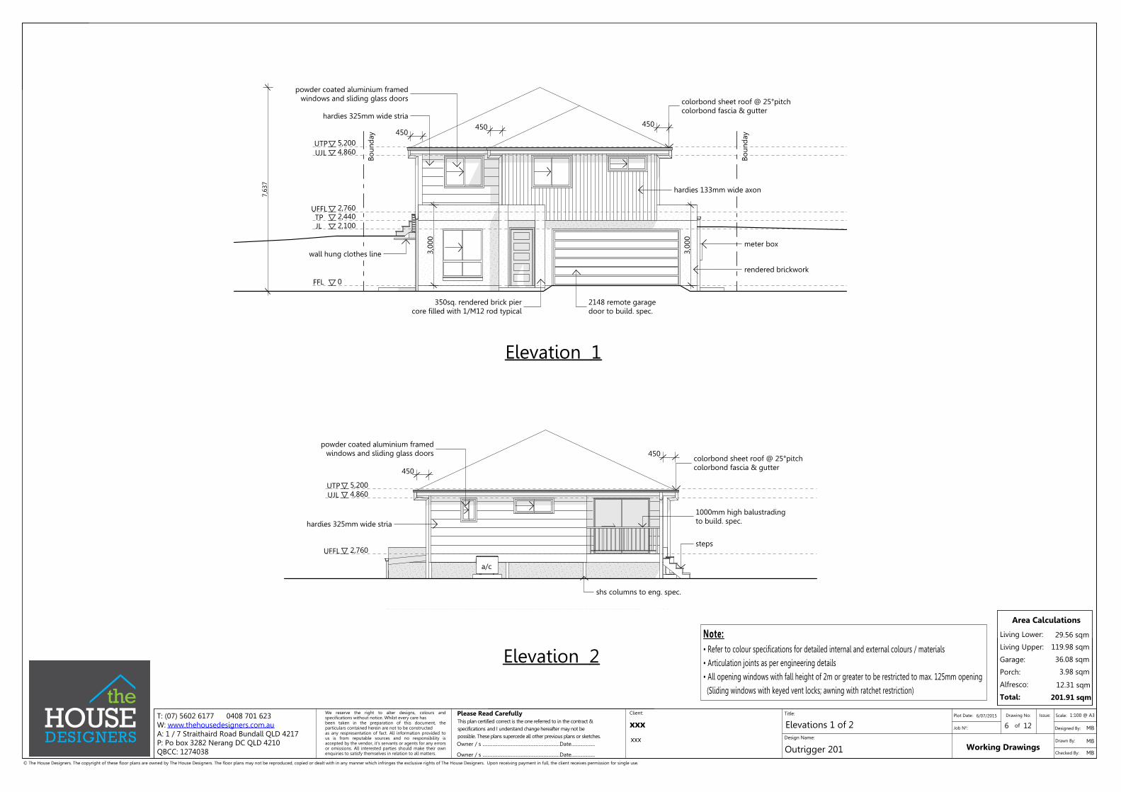
450
450
colorbond sheet roof @ 25°pitchcolorbond fascia & gutter
powder coated aluminium framedwindows and sliding glass doors
steps
1000mm high balustradingto build. spec.
4,8605,200
2,760
hardies 325mm wide stria
shs columns to eng. spec.
a/c
UFFL
UTPUJL
2,440
0
2,100
4,8605,200
2,760
3,00
0
3,00
0
450450
450
rendered brickwork
colorbond sheet roof @ 25°pitchcolorbond fascia & gutter
wall hung clothes line
hardies 325mm wide stria
powder coated aluminium framedwindows and sliding glass doors
hardies 133mm wide axon
meter box
UFFL
UTPUJL
JL
FFL
TP
Boun
day
Boun
day
7,63
7
2148 remote garagedoor to build. spec.
350sq. rendered brick piercore filled with 1/M12 rod typical
Note:• Refer to colour specifications for detailed internal and external colours / materials
• Articulation joints as per engineering details
• All opening windows with fall height of 2m or greater to be restricted to max. 125mm opening
(Sliding windows with keyed vent locks; awning with ratchet restriction)
1:100 @ A3
Elevation 1
Elevation 2

Area Calculations
Living Lower:
Living Upper:
Garage:
Porch:
Alfresco:
Total:
3.98 sqm
201.91 sqm
36.08 sqm
12.31 sqm
119.98 sqm
29.56 sqm
Working Drawings
Elevations 2 of 2Design Name:
Title:
Checked By:
Drawing No: Scale:Client:
7 of
Outrigger 201
Job No:
Drawn By:
Issue:Plot Date: 6/07/2015
Designed By:xxx
xxx
12
MBOwner / s ..............................................................Date...................
Owner / s ..............................................................Date...................
Please Read CarefullyWe reserve the right to alter designs, colours andspecifications without notice. Whilst every care hasbeen taken in the preparation of this document, theparticulars contained herein are not to be constructedas any respresentation of fact. All information provided tous is from reputable sources and no responsibility isaccepted by the vendor, it's servants or agents for any errorsor omissions. All interested parties should make their ownenquiries to satisfy themselves in relation to all matters.
© The House Designers. The copyright of these floor plans are owned by The House Designers. The floor plans may not be reproduced, copied or dealt with in any manner which infringes the exclusive rights of The House Designers. Upon receiving payment in full, the client receives permission for single use.
MB
This plan certified correct is the one referred to in the contract &specifications and I understand change hereafter may not bepossible. These plans supercede all other previous plans or sketches.
MB
T: (07) 5602 6177 0408 701 623W: www.thehousedesigners.com.auA: 1 / 7 Straithaird Road Bundall QLD 4217P: Po box 3282 Nerang DC QLD 4210QBCC: 1274038
2,440
0
2,100
4,8605,200
2,760
3,00
0
450450
450
colorbond sheet roof @ 25°pitchcolorbond fascia & gutter
powder coated aluminium framedwindows and sliding glass doors
hardies 133mm wide axon
rendered brick sectioncore filled with 1/M12 rod typical
hardies 325mmwide stria
a/c unit
tiered rock retaining wallmax. height 1m
HWS (gas)
Boun
day
Boun
day
UFFL
UTPUJL
JL
FFL
TP
wall hung clothes line
1000mm high balustradingto build. spec.
steps
shs columns to eng. spec.
NGLFGL
HWS (gas)
a/c
NGL
NGL
NGL
Note:• Refer to colour specifications for detailed internal and external colours / materials
• Articulation joints as per engineering details
• All opening windows with fall height of 2m or greater to be restricted to max. 125mm opening
(Sliding windows with keyed vent locks; awning with ratchet restriction)
2,440
0
2,100
4,8605,200
2,760
3,00
0
450450
3,00
0
hardies 325mm wide stria
powder coated aluminium framedwindows and sliding glass doors colorbond sheet roof @ 25°pitch
colorbond fascia & gutter
a/c unit
350sq. rendered brick piercore filled with 1/M12 rod typical
Boun
day
Boun
day
UFFL
UTPUJL
JL
FFL
TP
shs columns to eng. spec.
HWS (gas)
tiered rock retaining wallmax. height 1m
m/box
NGL
NGL
FGL
FGL
NGL
1:100 @ A3
Elevation 3
Elevation 4

Area Calculations
Living Lower:
Living Upper:
Garage:
Porch:
Alfresco:
Total:
3.98 sqm
201.91 sqm
36.08 sqm
12.31 sqm
119.98 sqm
29.56 sqm
Working Drawings
Sections / DetailsDesign Name:
Title:
Checked By:
Drawing No: Scale:Client:
8 of
Outrigger 201
Job No:
Drawn By:
Issue:Plot Date: 6/07/2015
Designed By:xxx
xxx
12
MBOwner / s ..............................................................Date...................
Owner / s ..............................................................Date...................
Please Read CarefullyWe reserve the right to alter designs, colours andspecifications without notice. Whilst every care hasbeen taken in the preparation of this document, theparticulars contained herein are not to be constructedas any respresentation of fact. All information provided tous is from reputable sources and no responsibility isaccepted by the vendor, it's servants or agents for any errorsor omissions. All interested parties should make their ownenquiries to satisfy themselves in relation to all matters.
© The House Designers. The copyright of these floor plans are owned by The House Designers. The floor plans may not be reproduced, copied or dealt with in any manner which infringes the exclusive rights of The House Designers. Upon receiving payment in full, the client receives permission for single use.
MB
This plan certified correct is the one referred to in the contract &specifications and I understand change hereafter may not bepossible. These plans supercede all other previous plans or sketches.
MB
T: (07) 5602 6177 0408 701 623W: www.thehousedesigners.com.auA: 1 / 7 Straithaird Road Bundall QLD 4217P: Po box 3282 Nerang DC QLD 4210QBCC: 1274038
5,200
2,440
320
2,440
75lightweight cladding as per plans
10mm plasterboard wall liningpaint finish
timber framed walls asper framing schedule
damp proof course installationas per the current B.C.A.(minimum height of 75mm above finished surface level)
cornices as per builder's specifications
timber framed walls asper framing schedule
FC sheeting to soffit andabove windows
lintel as per framemanufacturer's specifications
wall ties in accordance with AS3700 Masonary code
colorbond fascia & gutterfixed to manufacturer'sspecs.
50x38 soffit bearers
1/30x0.8 G.I. straproof battens @ 900 cts (intermittent safety battens)to manufacturer's specifications
prefabricated timber roof trusses @ 600 cts.trusses to be engineer designed & fixed in accordancewith manufacturer's specifications & tie down details
selected colorbond sheeting
lintel as per framemanufacturer's specifications
10mm plasterboard wall liningpaint finish
steel lintel
10mm plasterboard fixed tounderside of joist
weepholes @ 900mm cts
metal flashing fixed in accordance withmanufacturer's specifications
cornices as per builder'sspecifications
brick sill flashing / weep hole
brick sill
slab edge exposure, visual termite risk management (vertical)minimum height of 75mm above finished surface levelas per B.C.A
concrete slab & footings toengineer's detail & design
polystyrene waffle pod
10mm plasterboard lining to ceilings fixedto metal furring channels a @450 cts
OVERHANG AS PER PLANS
ROOF PITCH AS PER PLANS
Detail 1 N.T.S
penetration pipe with foam lagginginstalled in accordance with B.C.A
waffle slab & footings toengineer's specifications
2,440
0
2,100
4,8605,200
2,760
prefabricated timber roof trusses @ 600 cts.trusses to be designed & fixed in accordancewith manufacturer's specifications & tie down details
10mm plasterboard linings to ceiling
UFFL
UTPUJL
JL
FFL
TPDETAIL 1
concrete slab & footing toengineers design & detail
colorbond sheet roof @ 25°pitchcolorbond fascia & gutter
as per dwg
Section A 1:100 @A3

Area Calculations
Living Lower:
Living Upper:
Garage:
Porch:
Alfresco:
Total:
3.98 sqm
201.91 sqm
36.08 sqm
12.31 sqm
119.98 sqm
29.56 sqm
Working Drawings
Slab LayoutDesign Name:
Title:
Checked By:
Drawing No: Scale:Client:
9 of
Outrigger 201
Job No:
Drawn By:
Issue:Plot Date: 6/07/2015
Designed By:xxx
xxx
12
MBOwner / s ..............................................................Date...................
Owner / s ..............................................................Date...................
Please Read CarefullyWe reserve the right to alter designs, colours andspecifications without notice. Whilst every care hasbeen taken in the preparation of this document, theparticulars contained herein are not to be constructedas any respresentation of fact. All information provided tous is from reputable sources and no responsibility isaccepted by the vendor, it's servants or agents for any errorsor omissions. All interested parties should make their ownenquiries to satisfy themselves in relation to all matters.
© The House Designers. The copyright of these floor plans are owned by The House Designers. The floor plans may not be reproduced, copied or dealt with in any manner which infringes the exclusive rights of The House Designers. Upon receiving payment in full, the client receives permission for single use.
MB
This plan certified correct is the one referred to in the contract &specifications and I understand change hereafter may not bepossible. These plans supercede all other previous plans or sketches.
MB
T: (07) 5602 6177 0408 701 623W: www.thehousedesigners.com.auA: 1 / 7 Straithaird Road Bundall QLD 4217P: Po box 3282 Nerang DC QLD 4210QBCC: 1274038
Nor
th
East
Sout
h
west
6,060 1,950
3,02
035
01,
010
350
275
4,81
062
5
1,50
03,
370
1,00
06,
070
10,4
40
7,060
7,060 950
1,400 3,600 2,060
10,4
40
2,628 2,628 2,628 1,050
2,628 2,628 2,628 1,050
2,89
32,
893
2,89
3
500
1,10
02,
040
1,100 4,695
70 900 900
70
3,715 900
900
70
11,72
6 CL t
o CL
12,603
380 1,500 970
695
705
310
310
1,600 350
1,000
2,0003,730
3,14
07015
070
1,08
090
230 1,000
1,00
0
16,045
25mm rebate for garagedoor opening
floor joists @ 450 cts.as per engineers documentation
shs to eng. spec.
bearers as per as perengineers documentation
footings / shs columnspoured & positioned at same time as main slab
above
86mmstepdown
fw 86m
mst
epd
ow
n
col. conc.
col. conc.
lbw
lbw
lbw
Under Slab Points
Floor Wastefw
Bearers & joists
As specified by engineer designed & fixed in accordancewith manufacturer's specifications & tie down details
cl cl clcl
cl
clcl
cl
cl
cl
cl
cl
cl
cl
cl
shower recessinto joists
shower recessinto joists
col. conc.
col. conc.
cl
col. conc.
86mmstepdown
lbw
FFL RL 7.810PAD RL 7.500
1:100 @ A3

Area Calculations
Living Lower:
Living Upper:
Garage:
Porch:
Alfresco:
Total:
3.98 sqm
201.91 sqm
36.08 sqm
12.31 sqm
119.98 sqm
29.56 sqm
Working Drawings
Electrical PlanDesign Name:
Title:
Checked By:
Drawing No: Scale:Client:
10 of
Outrigger 201
Job No:
Drawn By:
Issue:Plot Date: 6/07/2015
Designed By:xxx
xxx
12
MBOwner / s ..............................................................Date...................
Owner / s ..............................................................Date...................
Please Read CarefullyWe reserve the right to alter designs, colours andspecifications without notice. Whilst every care hasbeen taken in the preparation of this document, theparticulars contained herein are not to be constructedas any respresentation of fact. All information provided tous is from reputable sources and no responsibility isaccepted by the vendor, it's servants or agents for any errorsor omissions. All interested parties should make their ownenquiries to satisfy themselves in relation to all matters.
© The House Designers. The copyright of these floor plans are owned by The House Designers. The floor plans may not be reproduced, copied or dealt with in any manner which infringes the exclusive rights of The House Designers. Upon receiving payment in full, the client receives permission for single use.
MB
This plan certified correct is the one referred to in the contract &specifications and I understand change hereafter may not bepossible. These plans supercede all other previous plans or sketches.
MB
T: (07) 5602 6177 0408 701 623W: www.thehousedesigners.com.auA: 1 / 7 Straithaird Road Bundall QLD 4217P: Po box 3282 Nerang DC QLD 4210QBCC: 1274038
W/M
/S
m/box
HW
S
sgpo on ceiling forgarage door motor
water proof sgpo forgas HWS
wp
1500
300
two-way
1500
Nor
th
East
Sout
h
west
T.V Point
Exhaust Fan on separate switch controlvented into ceiling space
Air Conditioner - Internal Unit
Air Conditioner - External Unit
Electrical Legend
Single power outlet
Phone point
Double power outlet
Single power outlet (water proof)
Round Oyster Fluro Light Point - 36w
feature downlight point - 18w
Wall mounted flood light point - 120w
Smoke detector
wp
wp
a/c int.
a/c ext.
Down light point - 18w (CFL)
Double fluorescent light point - 36w
Single fluorescent light point - 36w
Double power outlet (water proof)
Ceiling fan
Ceiling fan / light
Light Switches
Wall Mounted Lights
Power Outlets (Standard)
@ 1150 AFL
@ 2000 AFL
@ 300 AFL
Power Outlets (Other)
Microwave Oven (Oven Tower) @ 1800 AFL
@ 700 AFL
Ventilation to internal wc, bath, ensuiteto be an exhaust fan in accordance withBCA F5.4 & AS - 1668.2
Vantiy Basins @ 1050 AFL
Laundry Bench @ 1050 AFL
Washing Machine @ 1500 AFL
Kitchen Bench @ 1050 AFL
Refrigerator @ 1500 AFL
Dishwasher @ 300 AFL
Rangehood @ 1800 AFL
Microwave Oven (Under Bench)
Electrical Notes
Class 1 building (5w/m2)
Artifical lighting total allowance(watts)
985 (watts)
Actual Wattstotal used
696 (watts)
Exhaust Fan on light switch controlvented externally unless stated otherwise
Down light point - 18w (LED)
P'TRYF/S 900
900900
UP1234
a/c
ext.
a/c
int.
a/c ext.
a/c int.
two-way
wp300
300
300
300
300
300
300
300
3001050
1050
300
DW
MO&O
1500
REF
300
300
RH
1800
two-way
1050
1050
1:100 @ A3
Lower Level
Upper Level

Area Calculations
Living Lower:
Living Upper:
Garage:
Porch:
Alfresco:
Total:
3.98 sqm
201.91 sqm
36.08 sqm
12.31 sqm
119.98 sqm
29.56 sqm
Working Drawings
Bracing PlanDesign Name:
Title:
Checked By:
Drawing No: Scale:Client:
11 of
Outrigger 201
Job No:
Drawn By:
Issue:Plot Date: 6/07/2015
Designed By:xxx
xxx
12
MBOwner / s ..............................................................Date...................
Owner / s ..............................................................Date...................
Please Read CarefullyWe reserve the right to alter designs, colours andspecifications without notice. Whilst every care hasbeen taken in the preparation of this document, theparticulars contained herein are not to be constructedas any respresentation of fact. All information provided tous is from reputable sources and no responsibility isaccepted by the vendor, it's servants or agents for any errorsor omissions. All interested parties should make their ownenquiries to satisfy themselves in relation to all matters.
© The House Designers. The copyright of these floor plans are owned by The House Designers. The floor plans may not be reproduced, copied or dealt with in any manner which infringes the exclusive rights of The House Designers. Upon receiving payment in full, the client receives permission for single use.
MB
This plan certified correct is the one referred to in the contract &specifications and I understand change hereafter may not bepossible. These plans supercede all other previous plans or sketches.
MB
T: (07) 5602 6177 0408 701 623W: www.thehousedesigners.com.auA: 1 / 7 Straithaird Road Bundall QLD 4217P: Po box 3282 Nerang DC QLD 4210QBCC: 1274038
BRACING TYPES USED:Type (h) Method B - Plywood-Minimum length of panels may be 600mm-Plywood shall be fixed to frame in a/w AS1684.2 using 30 x 2.8mm diam. galvanized flathead nails or equivalent-Fastener spacing; top and bottom plate 150mm, vertical edges 150mm, intermediate studs 300mm-Bracing capacity of Type (h) Method B is 6.0kN/m
Type (d) - Metal angle brace-Maximum depth of notch shall not exceed 20mm-Length of bracing 1800mm min. to 2700mm max.-Bracing capacity of Type (d) is 3.0kN/m-Metal angle of min. nominal section of 18 x 16 x 1.2mm must be fixed to frame in a/w AS1684.2 -2/30 x 2.8mm diam. nails to each stud -30 x 0.8mm galv. strap 3/30 x 2.8mm diam. galv. flathead (or equivalent) nails to each end to stud
-Nominal fixings to all timber members in accordance with relevant standards; AS1684.2, AS1684.3-M12 Cyclone rods to either side of external openings over 1800mm wide for N1, N2, N3 Sheet roofing
BATTENS / TRUSSES-1/No 14 Type 17 x 75mm screws, or as per truss manufacturer's specificationsTRUSS / TOP PLATE-1/30 x 0.8mm G.I. strap over each truss, 4/2.8mm diam. nails each end-Girder truss to have 2/30 x 0.8mm G.I. straps, 4/2.8mm diam nails each endLINTEL / TOP PLATE-30 X 0.8mm looped strap @900 crs max, 4 nails each endLINTEL / JAMB STUD-30 x 0.8mm G.I. strap @900 crs max, 4/2.8mm diam. nails each endBOTTOM PLATE / CONCRETE SLAB-1/75mm masonry nail, screw or bolt @1200 crs max.
STRUCTURAL BRACING:-For wall heights greater than 2700mm the bracing capacity of bracing walls is reduced and mustbe recalculated using the values given in Table 8.1.9 of AS1684.2/AS1684.3.-Bracing shall initially be placed in external walls and where possible at the corners of the building.Remaining bracing shall be evenly distributed throughout building.-Bracing shall not be placed on external walls under the eaves unless suitable connections to themain ceiling diaphragms are provided.-The maximum distance between braced walls at right angles to the building length/width shall notexceed 9000mm for wind classification N2. For wind classification greater than N2 spacing shall bein accordance with Table 8.20 and 8.21 in AS1684.2./AS1864.3.-All internal bracing walls shall be fixed to the floor, ceiling and/or external wall frame withstructural connections of equivalent shear capacity to the bracing capacity of that particular bracingwall.
ROOF TRUSSES and ROOF BRACING:-To be designed by truss manufacturer to comply with AS1684.2, AS1720 and AS4440.
TEMPORARY BRACING NOTES:-The builder is to ensure that the building is adequately braced during construction.-Temporary bracing shall be equivalent to at least 60% of the permanent bracing required.-Temporary bracing may form part of the installed permanent bracing.
NOMINAL WALL BRACING:-Nominal bracing, wall frames lined with sheet material such as plywood, plasterboard or fibrecement, may provide up to 50% resistance of the total racking forces.-Wall frames must be nominally fixed to the floor and roof frame.-Nominal bracing shall be evenly distributed throughout the building.-Minimum length of nominal bracing walls shall be 450mm.-Sheeted one side only: Bracing capacity 0.45kN/m-Sheeted two sides: Bracing capacity 0.75kN/m-1/75mm masonry nail, screw or bolt @1200 crs max.
Bracing Notes
Tie-Down Schedule
Nor
th
East
Sout
h
west
600
Ply
900 Ply900 Ply
900 Ply
900 Ply
900 Ply
900
Ply
900
Ply
900
Ply
900
Ply
900
Ply
900
Ply
900
Ply
XDirection N2Type
Ply Brace
Ply Brace
Length
600
900
Resistance
6.0 kN/lm
6.0 kN/lm
Qty. Total (kN)
Total Resistance Achieved
Metal Strapping(double cross)
2000 3.0 kN/lm
Sheet Roof YDirection N2Type
Ply Brace
Ply Brace
Length
600
900
Resistance
6.0 kN/lm
6.0 kN/lm
Qty. Total (kN)
Total Resistance Achieved
Metal Strapping(double cross)
2000 3.0 kN/lm
27.00
Sheet Roof
05 37.8007
Upper Level - 11.92 kN Required
6.0 kN/lm
3.0 kN/lm
N2Direction
Ply Brace
Type
Y
600
Length Resistance
900 6.0 kN/lm
6.0 kN/lm
Total (kN)Qty.
Ply Brace
X
2000
Total Resistance Achieved
600
N2Qty. Total (kN)
Direction
Type
900
Sheet Roof
Metal Strapping(double cross)
Length
Ply Brace
Metal Strapping(double cross) 3.0 kN/lm
06 32.40
Resistance
Total Resistance Achieved
2000
6.0 kN/lm
Ply Brace
Sheet Roof
43.2008
50.40
Direction - X Direction - Y
Lower Level - 32.68 kN Required
X - Total Required - 44.60 kN
Upper Level - 41.16 kN Required
Lower Level - 45.20 kN Required
Y - Total Required - 86.36 kN
27.00
X - Total Achieved - 59.40 kN Y - Total Achieved -97.80 kN
41.40
3.601
7.2002
32.40
Direction - Y
N2
Dir
ecti
on
- X
44.60 Kn Bracing Required
59.40 Kn Bracing Achieved
86.3
6 Kn
Bra
cing
Req
uir
ed
97.8
0 Kn
Bra
cing
Ach
ieve
d
Sheet Roof
Denotes Tie-Down Rod
not part of calculation
not part of calculation
600
Ply
900 Ply
900 Ply
900 Ply900 Ply
900 Ply
900 Ply
900
Ply
900
Ply
900
Ply
900
Ply
900
Ply
900
Ply
900
Ply
900
Ply
600
Ply
450
Ply
450
Ply
1:100 @ A3
Lower Level
Upper Level

Area Calculations
Living Lower:
Living Upper:
Garage:
Porch:
Alfresco:
Total:
3.98 sqm
201.91 sqm
36.08 sqm
12.31 sqm
119.98 sqm
29.56 sqm
Working Drawings
Landscaping PlanDesign Name:
Title:
Checked By:
Drawing No: Scale:Client:
12 of
Outrigger 201
Job No:
Drawn By:
Issue:Plot Date: 6/07/2015
Designed By:xxx
xxx
12
MBOwner / s ..............................................................Date...................
Owner / s ..............................................................Date...................
Please Read CarefullyWe reserve the right to alter designs, colours andspecifications without notice. Whilst every care hasbeen taken in the preparation of this document, theparticulars contained herein are not to be constructedas any respresentation of fact. All information provided tous is from reputable sources and no responsibility isaccepted by the vendor, it's servants or agents for any errorsor omissions. All interested parties should make their ownenquiries to satisfy themselves in relation to all matters.
© The House Designers. The copyright of these floor plans are owned by The House Designers. The floor plans may not be reproduced, copied or dealt with in any manner which infringes the exclusive rights of The House Designers. Upon receiving payment in full, the client receives permission for single use.
MB
This plan certified correct is the one referred to in the contract &specifications and I understand change hereafter may not bepossible. These plans supercede all other previous plans or sketches.
MB
T: (07) 5602 6177 0408 701 623W: www.thehousedesigners.com.auA: 1 / 7 Straithaird Road Bundall QLD 4217P: Po box 3282 Nerang DC QLD 4210QBCC: 1274038
Nor
th
East
Sout
h
west
1.8m high fence & gate return1m back from front building line
dismantle existing footpathreplace with coloured concrete
coloured concrete driveway finish
drainage catch basins as required
rock retaining wallmax height 1m
tiered rock retaining wallmax height 1m
denotes batter
McG
rego
rPl
ace
LOT 2406374 M2
gate
L
1.8m high fence return1m back from front building line
rock retaining wallmax height 1m
FFL RL 7.810PAD RL 7.500
FFL RL 10.570PAD (FGL) 9.600 approx.
Landscaping / Planting Legend
WaterhousiaFloribunda
SyzguimAustrale
2D PlantSymbol
Name
Pot Size
Width
Height
LxoraCoccinea
Liriope"Evergreen Giant"
DietesBicolor
45l 200ml 200ml 140ml 140ml
3.5m 1.5-2.0m 2.0m 0.8m 1.0m
8m 0.5-1.0m 0.5-1.0m 0.6m 0.8m
All plant species & quantities are indicative and subject to availability and suitability to site. Should aparticular nominated plant not be available an equilavant replacement shall be used.
coloured concrete
Garden Mulch
'A' grade turf
1800mm high timber fence
paved garden edging to front / timber to rear
Legend
timber retaining wall
rock retaining wall
Rubbish Bins
Rendered Leterbox
R B
L
1500mm high timber toprail & posts with poolstyle infill fencing
direction of fall
river pebbles (20 - 40mm, weed mat under)
1:200 @ A3