WORK PRACTICE FOR FRECONDUITS UNDERGROUND … Complete … · A third alternative for conduit...
39
WORK PRACTICE FOR FRE® CONDUITS UNDERGROUND INSTALLATIONS F I R S T I N T H E F I E L D
Transcript of WORK PRACTICE FOR FRECONDUITS UNDERGROUND … Complete … · A third alternative for conduit...

WORK PRACTICE FOR FRE® CONDUITS
UNDERGROUND INSTALLATIONS
F I R S T I N T H E F I E L D
mcharron
Typewritten text
®
mcharron
Typewritten text
®

Work Practice
for Underground Installations
Introduction This guide has been written with the assumption that the conduit bank will be exposed to considerable vehicular traffic during its lifetime. Many of the techniques and precautions discussed have been done so with this in mind. In areas of reduced traffic magnitude and frequency many of the recommendations stressed in this guide become unnecessary or unimportant. Because of this, considerable variation is possible from the techniques outlined here without any harm or series effect on the conduit’s performance of its function. Many alternate techniques will work equally well in non-demanding applications. The main aim has been to present the true capabilities of direct burial FRE® conduit in demanding situations where concrete encasement would routinely have been used.
This document is the property of FRE Composites (2005) Inc. It shall not be used, reproduced, copied or transmitted to other persons without written authorization from FRE Composites (2005) Inc. - © 2005. All rights reserved, FRE Composites Inc.
www.frecompos i tes .com 3
This document is the property of FRE Composites (2005) Inc. It shall not be used, reproduced, copied or transmitted to other persons without written authorization from FRE Composites (2005) Inc. - © 2005. All rights reserved, FRE Composites Inc.
mcharron
Typewritten text
®

Table of Contents
Work Practice for Underground Installations
1. BURIAL ALTERNATIVES 1
1.1 - CONCRETE ENCASEMENT 1 1.2 - DIRECT BURIAL 1 1.3 - DIRECT BURIAL WITH COVER SLABS 2
2. CONDUIT BANKS 4
2.1 - CONDUIT BANK CONSIDERATIONS 4 2.2 - CONDUIT BANK ROUTING 5 2.3 - MANHOLES 7
3. CONDUIT BEHAVIOR THEORY 8
3.1 - RIGID CONDUIT 8 3.2 - FLEXIBLE CONDUIT 8 3.3 - FLEXURAL CONDUIT DESIGN CONSIDERATIONS 9 3.4 - SOIL CONDITIONS AND CONSIDERATIONS 10
4. DIRECT BURIAL TECHNIQUES 13
4.1 - TRENCH EXCAVATION AND PREPARATION 13 4.2 - CONDUIT INSTALLATION 14
APPENDIX 1 19
SOIL LOAD: 19 TRAFFIC LOADS: 20 DEFLECTIONS: 24 DEFLECTION TABLES
4 www.frecompos i tes .com
5
556
8
89
11
12
12121314
17
1718
23
232428
mcharron
Typewritten text
®

1. Burial Alternatives
1.1 - Concrete Encasement
There are various reasons which may dictate that a conduit bank must be concrete encased as illustrated in Figure 1.1. Often there is a rigid municipal code requiring specific ducting to be concrete encased. There may exist a condition where the bank must be buried in a concrete envelope to provide the strength to overcome future loads. In other situations, the installation is in an area, which is subjected to repeated excavation. Concrete is required to provide protection from an accidental dig-in. In such cases, the concrete would provide protection against a disruption of service and in the case of power cables, will help to prevent electrocution.
This document is the property of FRE Composites (2005) Inc. It shall not be used, reproduced, copied or transmitted to other persons without written authorization from FRE Composites (2005) Inc. - © 2005. All rights reserved, FRE Composites (2005) Inc.
1.2 - Direct Burial
Direct burial is a technique whereby the conduits are placed underground without a concrete envelope as illustrated in Figure 1.2. This technique is advantageous anywhere that concrete encased banks are used provided that enough depth is available for a proper installation and that the area is not subjected to repeated digging. The advantage of this method is that it completely eliminates the need for concrete, thus saving money and the time needed to make up forms, haul away excavated soil, etc. In some instances the direct buried conduit may actually provide a better and safer installation than with concrete encasement. Areas subject to a lot of frost heaving or to uneven settlement may cause the concrete envelope to shear apart, thus transmitting to the conduit extremely high shear loads. This will eventually lead to failure of the conduit and probably the cables contained within as illustrated in Figure 1.3. Unrestrained conduits would have shifted position slightly under these forces and hence remain undamaged due to their mobility.
Figure 1.1
Concrete Encased Conduit Bank
Figure 1.2 Direct Buried Conduit Bank
www.frecompos i tes .com 5
mcharron
Typewritten text
®

Figure 1.3 Conduit bank damaged through shear forces on concrete
1.3 - Direct Burial with Cover Slabs
A third alternative for conduit installation is a direct burial technique employing concrete cover slabs for protection. In this way, all the benefits and economy of direct burial are realized but with the additional dig-in protection afforded by the concrete cover slab as shown in Figure 1.4.
These concrete covers serve a dual purpose. While providing protection from dig-ins, which might damage the conduit, they also act as a load distribution platform. When a heavy load passes over the conduit bank, the load acts on the slab and is then distributed over a larger area, thus reducing the concentration on the conduit as demonstrated in Figure 1.5. This additional load distribution process may allow shallower burial depths in many instances.
Figure 1.4 Direct burial with cover slabs
6 www.frecompos i tes .com
mcharron
Typewritten text
®

Figure 1.5
Load distribution with cover slabs
When laying out a conduit run, it may become necessary to cross over other systems, which are already buried in the area. In these cases, it is recommended to also include a lower slab under the conduit for isolating the two (2) systems as shown in Figure 1.6. This is particularly necessary when passing over steam or water lines. A burst pipe can wash away much of the soil and undermine the conduit possibly causing the duct bank to cave in when an overburden load is applied. The concrete base slabs offer some protection from these occurrences by providing a firm foundation for the conduit bank.
Figure 1.6 Conduit bank with upper & lower
concrete slabs
This document is the property of FRE Composites (2005) Inc. It shall not be used, reproduced, copied or transmitted to other persons without written authorization from FRE Composites (2005) Inc. - © 2005. All rights reserved, FRE Composites (2005) Inc.
www.frecompos i tes .com 7
mcharron
Typewritten text
®

2. Conduit Banks
2.1 - Conduit Bank Considerations
The primary function of a conduit system is to provide a reliable carrier for electrical and telecommunication cables. Prior to designing the system, the number and size of the cables to be installed must be known both for present and future requirements. The size of conduit selected will be based on the size of the largest cable, which will be installed, or the largest grouping of cables in the case where multiple cables share a single conduit. In the case of power cables, conduit fill should be carefully calculated to ensure compliance with local regulations and to facilitate cable pulling and removal, if necessary.
Figure 2.1
Multi-duct banks where central conduits exhibit poor heat dissipation
The bank configuration should be carefully considered especially in the case where power cables are to be installed. Since cables carrying power become heated from the electrical losses in the conductors, their natural cooling must be allowed for in the conduit bank arrangement. As can be seen above in Figure 2.1 certain interior conduits may not be desirable for power cables since their location does not allow them to radiate heat away effectively. In these situations these center conduits should be used for control cables, street lighting or perhaps left empty for future requirements.
Attempts to use these interior conduits for carrying power cables usually means that all the cables must be derated and/or the power transmission reduced to prevent overheating. In such instances, these factors more than nullify any advantage gained from using the center vent overheating. In such instances, these factors more than nullify any advantage gained from using the center conduits and thus as a rule they are usually left empty. To avoid excessive unusable conduits, or problems with heat dissipation, a recommended maximum of conduits in a single run for power cables is generally nine (9).
8 www.frecompos i tes .com
mcharron
Typewritten text
®

The number of conduits selected for a run will depend upon the number required for the immediate project plus the number of spares to be provided for future use. It is usually calculated that the number of spares increases as the site of the bank increases. A rule sometimes used is to provide a spare conduit for each conduit, which will be immediately used. In this way, there is a provision for a 100% increase in the service at a future date. When the cost of installing spare conduits is calculated, versus the cost of installing a new duct bank one (1) or two (2) years down the road, it makes sense to add these spares in the initial installation.
2.2 - Conduit Bank Routing
The conduit run should be located so that it will be subject to a minimum of disturbances once it is installed. This is done in the interest of safety for working personnel and for the conduit run itself. Routes through mud, shifting soils and other unstable areas are to be avoided.
The top of the conduit system is generally located at a depth of 30 to 36 in. or 762 to 914 mm below the finished surface, but rarely at less than 24 in. or 610 mm of depth. The reason for this is that live loads from traffic are extremely high at very shallow burial depths and could cause conduit damage at depths of less than 1 ft. or 0.3 m in certain cases. This load is considerably reduced at 3 ft. or 0.9 m of depth, and may be ignore completely for depths of over 8 ft. or 2.4 m. Where rail traffic is involved, the burial depths should be increased accordingly to compensate for the higher live loads generated by rail vehicles.
When laying out the proposed conduit run, one should strive to keep the route as straight as possible. Where direction changes are indicated due to obstructions in the route, the angular displacement should be maintained as small as possible. The total angular displacement of the conduit run is determined by adding up the angles of each direction change to find the sum total as can be seen in Figure 2.2. Cases where there is a change in the vertical plane must be included in the total summation also.
Figure 2.2
Angular displacement of conduit runs
This document is the property of FRE Composites (2005) Inc. It shall not be used, reproduced, copied or transmitted to other persons without written authorization from FRE Composites (2005) Inc. - © 2005. All rights reserved, FRE Composites (2005) Inc.
www.frecompos i tes .com 9
mcharron
Typewritten text
®

The total angular displacement of the run limits the length of the run between manholes. As the total angle increases, the length of the run permitted decreases. Figure 2.3 shows a chart, which may be used as a guide in determining the practical length of run for a specified total angle of deflection. These tabled figures should not be regarded as limits, but rather as guidelines since considerable variation is possible from one job to the next. Many runs employing FRE® conduit with its low coefficient of drag have gone well over 1000 ft. or 304.8 m without any difficulty. Also very gentle sweeping elbows usually allow much longer runs than when prefabricated tight radius elbows are used.
Figure 2.3
Approximate Relationship Between Angular Deflection and Length of Run
Where an angular change occurs in the run, the radius of curvature connecting the two (2) straight sections should be maintained as large as possible to facilitate cable pulling. For very small direction changes it is usually possible to bend the conduit lengths sufficiently to provide a direction change without use of prefabricated elbows or fittings. This method is ideal when possible as it imparts only a minimum of drag to the cable pulling operation. These bends made with straight FRE® conduit lengths are usually limited to 5° or less per stick (length) to avoid imposing excessive stresses to the conduit, which may cause damage.
10 www.frecompos i tes .com
mcharron
Typewritten text
®

This document is the property of FRE Composites (2005) Inc. It shall not be used, reproduced, copied or transmitted to other persons without written authorization from FRE Composites (2005) Inc. - © 2005. All rights reserved, FRE Composites (2005) Inc.
2.3 - Manholes
Manhole locations for the system are based on site conditions, access convenience and allowable length of cable pull. A good location for manholes is at a street intersection. It allows conduit runs to extend out in four (4) directions without the need of additional elbows or fittings. Spacing between manholes will depend on various factors but in practice, it seldom exceeds 700 to 800 ft. or 213.4 to 244 m in order to maintain relatively low pulling tensions and keep the cable pull simple. The low coefficient of friction of FRE® conduit may allow an increase in the manhole spacing without any appreciable change in the cable pulling tension.
The conduit runs between manholes are graded such that any water, which seeps in the conduit, will drain into the manhole. A minimum grade of 3 in. or 76 mm per 100 ft. or 30.5 m is recommended to ensure proper water drainage. This grade may be continuous from one (1) manhole to another or alternately may be designed with the high elevation at a midpoint, and the conduit sloping down towards each manhole. The entering site for the manhole is often a site of particular concern due to excessive soil settlement in this area. Uneven settlement at this interface can produce extremely high shear stresses on the conduit, which might lead to failure. Therefore, conduit at a manhole entrance should be installed on well compacted soil or otherwise supported with the FRE® wobble couplings, which are specifically designed to undergo moderate axial and lateral deflections without endangering the conduit.
www.frecompos i tes .com 11
mcharron
Typewritten text
®

3. Conduit Behavior Theory
3.1 - Rigid Conduit
For electrical classification purposes, duct and conduit are classified as rigid or flexible based on whether or not the product can be transported in coil form. For purposes of mechanical design however, duct and conduit may be regarded as rigid or flexible based on their mechanical performance characteristics. Conduits which are buried in the ground and whose subsequent mechanical performance is rigid in nature are mechanically regarded as "Rigid Conduits". Being classified as rigid implies that they cannot undergo deflections beyond minute amounts without undergoing some sort of structural damage. They tend to be high modulus, thick wall materials such as concrete, asbestos-cement or clay tile conduits. These conduits may carry any external loading stress by pure compression and can be assumed to derive no support from the surrounding soil as seen in Figure 3.1. Because of this behavior rigid conduits must be designed strong enough to support any anticipated load, which may be imposed on them, and any over-stressing causes immediate and catastrophic failure in the product.
Figure 3.1 Load on rigid Conduits
3.2 - Flexible Conduit
Flexible conduit is listed as rigid for the purpose of electrical classification, but for mechanical design purposes falls into a category commonly referred to as "Flexible Conduit". Because FRE® conduit performs as a flexible conduit does not imply that the material has no rigidity but rather it reflects on the conduits' behavior when buried. A flexible conduit drives its load carrying capabilities from the surrounding soil. This results from the materials ability to deform and hence transmit and distribute pipe push outward against the side-fill and thus transfer most of the vertical load into a horizontal pressure on the soil. This outward pressure on the side-fill material causes a mobilization of the passive resistance pressure of the soil. This passive earth pressure acting on each side of the conduit greatly reduces the conduits' deformation and the magnitude of the stresses in the conduit wall.
12 www.frecompos i tes .com
mcharron
Typewritten text
®

3.3 - Flexural Conduit Design Considerations
The peculiar behaviour of flexible conduits has in the past created uncertainty about the true strength of these materials. In flat plate compression tests in free air, rigid conduits will support naturally much more load than flexible conduits. These test results have often led people to believe that when buried, the rigid products would similarly carry the greater load. This is an incorrect assumption. The reason is that the flat plate crush strength of a flexible conduit is not a true indication of its loading capability in soil. Because of this the flat plate crush test results can be used as an appropriate measure of load bearing strength for rigid conduits but not for flexible conduits. It is also because of these different behaviours that care must be exercised when performing calculations relating to conduit performance. Appropriate formulas designed specifically for flexible conduits must be used for flexible conduit calculations as the formulas for rigid conduits do not apply and would thus produce erroneous results.
Tests have shown that loads developed on rigid conduits are greater than those developed on flexible conduits.* It was also noted that the greater load on rigid conduits tended to concentrate at the top and bottom surfaces creating high bending moments in the conduit wall. The surface loads developed on flexible conduit however were found to be more evenly distributed around the conduit circumference with less concentration on the top and bottom surfaces. The passive earth pressure also allowed these loads to be carried as compressive forces in the conduit wall as opposed to bending moment forces as in the case of rigid conduit.
Since flexible conduits divide the loads imposed upon them with the surrounding soil, it follows that the soil conditions and behaviour are of utmost importance when dealing with flexible conduit installations. Figures 3.2 and 3.3 illustrate examples of this. In Figure 3.2, we see a conduit sample under load in free air. In this instance, with no side support, the conduit is experiencing considerable deflection due to the applied load. This would not be acceptable for a conduit installation.
Figure 3.2
Parallel Plate Loading Test in Free Air
This document is the property of FRE Composites (2005) Inc. It shall not be used, reproduced, copied or transmitted to other persons without written authorization from FRE Composites (2005) Inc. - © 2005. All rights reserved, FRE Composites (2005) Inc.
* Reference AWWA Manual M-II “Steel Pipe Design & Installation” American Water Works Association, Denver Colorado 1964 p. 73.
www.frecompos i tes .com 13
mcharron
Typewritten text
®

Figure 3.3 shows the same conduit supporting the same load but this time, because that conduit is buried in the soil, its deflection is minimal and well within acceptable limits. The side-fill soil is carrying part of the load on the conduit through compressive forces at the sides of the conduit as it attempts to go oval. Naturally, the better the quality and compaction of the fill material, the more support it will provide for the conduit and hence, the lower the deflections will be.
Figure 3.3
Loading on Buried Conduit
3.4 - Soil Conditions and Considerations
Although the maximum load carrying capabilities of flexible conduits are dependent to some degree on the conduit wall thickness and material modulus, the soil plays a large part in determining the final load carrying capacity of the buried conduit.
Basically, the conduit must have enough stiffness to resist distortion during back filling and compaction; and strength to resist buckling after the loads are applied as well as the usual toughness required to withstand handling, transportation and adverse storage. The soil, on the other hand, must provide the stiffness to limit conduit deflection under load and to distribute loads to help the conduit resist buckling. In order for the soil to provide this support for the conduit, it should act as a stiff, uniform, elastic medium.
As a rule, the conduit bank design will be controlled so that under the maximum anticipated loads, the conduit itself will be limited to deflections of 5% or less. Since a given conduit’s deflection for a specified load varies inversely as the stiffness of the soil at the sides of the conduit, it follows that the deflection can only be reduced or restrained by increasing the soil stiffness. The soil stiffness will improve either with increased compaction or with selection of better quality fill materials. The best fill materials are those, which are generally found to be coarse and well drained.
14 www.frecompos i tes .com
mcharron
Typewritten text
®

This document is the property of FRE Composites (2005) Inc. It shall not be used, reproduced, copied or transmitted to other persons without written authorization from FRE Composites (2005) Inc. - © 2005. All rights reserved, FRE Composites (2005) Inc.
Close examination of the lower formula, which defines conduit deflection in a buried environment, reveals the soil dependence in the relationship as;
CONDUIT DEFLECTION = FUNCTION OF APPLIED LOAD
CONDUIT MODULUS + SOIL MODULUS
It is clear that to reduce and/or limit the deflection to 5%, one has three (3) alternatives;
1. Reduce the load (which may be imposed by rerouting of the conduit bank) or changing the burial depth.
2. Increase the conduits stiffness. 3. Increase the soil stiffness, which may be achieved by improving either, the
qualities of the fill material or the back filling and tamping techniques.
It can be seen from these alternatives that considerable leeway is possible. Usually however, the user will find that alternatives 1 and 2 have been settled and are beyond his control. This means that he can only affect the design with his back filling techniques and choice of materials. The problem therefore is not one of designing the conduit to suit the soil and the loading, but rather to selecting and designing the soil conditions to suit a conduit in a specific loading situation. The choice of material will have to be made so that the material chosen has a high modulus and is capable of attaining sufficient compaction density so that the deflection of the buried conduit will restricted to 5% or less. As a general guide the following rules will help in the selection of the proper material:
1. Usually a more granular soil has a higher modulus that a cohesive soil. 2. A granular soil is much easier to compact than a cohesive material. 3. Granular soils are much less sensitive to moisture content than are cohesive
materials 4. A higher degree of compaction is attainable from a granular material. 5. The modulus of a cohesive material generally remains unaffected by the pressure
exerted on it. 6. The modulus of a granular material improves with increasing pressure and
compaction. All these factors seem to again indicate that the coarser and well drained materials will be more suitable as fill materials. Table A-6 shows a breakdown of various soil types and their basic composition. The top of the chart indicates ideal back-fill materials with the progressively poorer materials encountered as one progresses down the table. The classes at the very bottom of the table are probably unsuitable as fill materials, except in areas where very minimal loading is expected. For average burial depths, particularly where H-20 loads are anticipated, one will require better quality materials such as those in the top third of the table, at least for the immediate conduit area. Poorer quality material may be used for topping off and final grading, provided care is taken in their placement.
www.frecompos i tes .com 15
mcharron
Typewritten text
®

Table A-7 provides a guide for estimating how much compaction is possible for each material group for various tamping techniques. As a rule, it is evident that material, which compacts well, will provide good support for the conduit. Generally, the use of clays is not recommended as they are not suitable materials where surface loads are anticipated. In addition, clay materials under load may flow with time, thus reducing the support on the conduit. Particular consideration should be given to the moisture content in the clay. It tends to hold considerable amounts of water, which affects it’s performance. Again, it should be stressed that only granular materials be used for heavy traffic areas.
Having made a choice on the fill material and the estimated compaction which will be achieved in the field, the engineer will be able to calculate fairly accurately the actual conduit deflection for any given depth and surface loading. Appendix I goes through these calculations in detail and Table A-5. It will provide a suitable modulus of soil reaction based on the engineer's choice of materials and compaction. This modulus will also be used to calculate the actual conduit deflection for the designed load and burial depth.
16 www.frecompos i tes .com
mcharron
Typewritten text
®

This document is the property of FRE Composites (2005) Inc. It shall not be used, reproduced, copied or transmitted to other persons without written authorization from FRE Composites (2005) Inc. - © 2005. All rights reserved, FRE Composites (2005) Inc.
4. Direct Burial Techniques
4.1 - Trench Excavation and Preparation
The first consideration prior to trench excavation is the depth of the trench. This depth will be calculated by the engineer, based on clearance required for other subgrade lines and equipment and on the height of cover needed for the conduit to adequately carry and be protected from surface (live) loads. As a rule, where traffic is anticipated the conduit should have about 30 in. or 762 mm of cover or more with 24 in. or 610 mm as an absolute minimum in special circumstances. For H-20 loading, 36 in. or 914 mm would be preferred.
The trench bottom is critical and should be inspected to ensure that it is undisturbed, firm and uniform for its entire length. This uniformity must be maintained to avoid differential settlement of the conduit, which could cause over-stressing, and damage of the material. If uniformity in the trench is not achieved, it would have to be over-excavated and the bottom refilled with good quality and properly compacted bedding materials. In extreme cases, where the subgrade is very poor, it may be necessary to lay a concrete foundation in the bottom of the trench to provide support.
When concrete is used as a base pad, a layer of granular material used as a cushion between the conduit and the concrete base is necessary. With a very hard or rocky bottom, a concrete base can be avoided but it is still recommended to use a similar layer of granular bedding as a cushion 4 in. or 101.6 mm is adequate for most installations.
When the trench bottom is undisturbed, firm and consisting of relatively smooth earth, no special preparations are required prior to the laying of FRE® conduit runs.
In order to do a proper evaluation of the trench bottom, it is suggested to excavate the entire run from manhole to manhole to allow initial inspection of the entire run, and avoid surprises later. Particular attention should be given to areas where the conduit bank will cross roadways as any settlement here would cause not only conduit but also road damage.
Conditions may be encountered where running or standing is discovered while excavating the trench. In such cases, pumps must be employed to drain the trench. This pumping must be continued during the back-filling operations, as it is imperative that the trench be kept free of water in order to compact the bedding material. Proper compaction levels of the bedding can only be achieved with relatively dry materials. In such cases, layers of underdrain bedding or well points, may be required under the first conduit layer to promote future drainage and prevent washout. Adverse conditions of this type will require engineering consultation and assistance to avoid future problems.
Such conditions are beyond the scope of this guide. As a rule, areas with permanently high water tables seem to coincide with very poor soil conditions hence, crushed rock or pea gravel will be necessary as a bedding and back-fill material.
www.frecompos i tes .com 17
mcharron
Typewritten text
®

The width of the trench will usually be determined by the stiffness and stability of the native soil. With a stable native soil, it is desirable to keep the trench width as narrow as possible while providing enough room for proper back-fill and compaction. Usually a width equal to one foot greater than the width of the conduit bank is ideal. In this way the greatest passive resistance of the undisturbed soil on the sidewalls can be realized. This applies with all stable native soils which generally means they possess bearing capacities of 3000 lb./ft. or 13 345 joule/meter to 3500 lb./ft. or 15 569 joule/meter or more.
When the native soil is soft and unstable (bearing capacities under 3000 lb./ft. or 13 345 joule/meter) it may be necessary to widen the trench somewhat. As shown on Figure 4.1, a narrow trench in poor soil may cause sidewall ovalization in the soft native soil due to vertical pressure on the conduit. To minimize this, it will be necessary to widen the trench such that the space between the conduit bank and the side of the trench is equal to about three (3) conduit bank diameters. This is based on Barnard’s Theory whereby it has been found that sidewall pressure from buried conduits dissipate at about two and a half (2 1/2) conduit bank diameters.
4.2 - Conduit Installation Figure 4.1 Trench Conditions in Soft
and Unstable Soils
Installation of the conduit should begin by placing a 2 in. or 50.8 mm layer of fill material into the bottom of the trench as a base for the bottom conduit tier. This material will provide a supporting cushion when subsequent layers are installed and assure protection of the bottom layer from damage. This will ensure adequate coverage under the conduit haunches. Such protection could be reduced if the fill was added after the conduit was put in place (as shown in Figure 4.2).
Figure 4.2 Lack of Fill Material Under Conduit
Haunches Due to Improper Installation Procedures
18 www.frecompos i tes .com
mcharron
Typewritten text
®

Care must be taken to excavate material from under the belled ends of the conduits to assure a smooth horizontal run as shown in Figure 4.3. This will ensure a perfectly straight alignment in the run and avoid excessive stress at the joints due to misalignment as shown in Figure 4.4.
Figure 4.3
Proper conduit alignment due to excavations at joint
Figure 4.4
Improper conduit alignment due to lack of joint allowance in trench bottom
The horizontal spacing of this first tier will be controlled by use of comb type separators. These can be economically produced as required and custom built to suit the particular conduit bank configuration, as required for the job. Figure 4.5 details the construction of a design, which has been found suitable for this type of work.
Dimensions “A” will be determined by the size of the conduit being used. Dimension “B” will determine the lateral spacing between conduits and it is generally suggested to use a value of 2 in. or 50.8 mm for this separation. The 2 in. or 50.8 mm space will allow adequate room for back-fill material to flow in between the conduits and fill the voids. The “C” dimension will govern the vertical spacing to the tiers and a 3 in. or 76.2 mm spacing is generally advised. The useful feature of this type of comb spacer is that it can be tailored to a specific job even if two (2) or three (3) different conduit sizes are to appear side by side in the same layer. One of these comb spacers every 6 ft. or 1.83 m will prove adequate for most jobs. Use of the rigid molded plastics or concrete spacers as are commonly used when duct is to be concrete encased. It is not recommended for this type of installation unless the fill is firm and can be well compacted.
This document is the property of FRE Composites (2005) Inc. It shall not be used, reproduced, copied or transmitted to other persons without written authorization from FRE Composites (2005) Inc. - © 2005. All rights reserved, FRE Composites (2005) Inc.
www.frecompos i tes .com 19
mcharron
Typewritten text
®

Because of their rigid nature, any shift or setting in the conduit bank (with poor compaction) would cause binding and point loading with plastic spacers. This point loading could provoke high shear stresses, which may damage the conduit. Comb separators as outlined in this guide, and which are later removed, allow no point of contact should a small amount of setting take place and hence, are one of the preferred techniques.
When the conduit has been laid, and the separators positioned between them, the first layer of fill is added. This material will be as selected by the engineer for the job in question and will be placed flush with the top of the spacers as shown in Figure 4.6. The material is now tamped as required to achieve the desired proctor density at which time the spacers are removed. When the spacers are removed, care must be taken to fill and tamp the voids created by their removal.
20 www.frecompos i tes .com
mcharron
Typewritten text
®
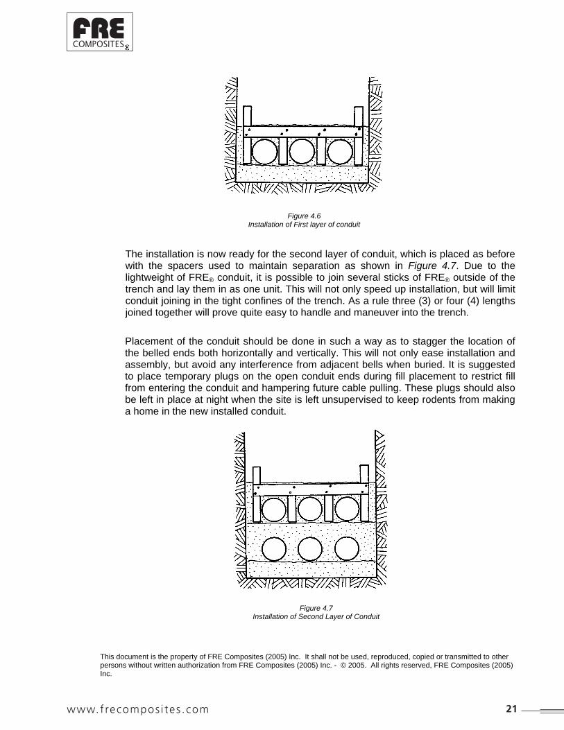
Figure 4.6 Installation of First layer of conduit
The installation is now ready for the second layer of conduit, which is placed as before with the spacers used to maintain separation as shown in Figure 4.7. Due to the lightweight of FRE® conduit, it is possible to join several sticks of FRE® outside of the trench and lay them in as one unit. This will not only speed up installation, but will limit conduit joining in the tight confines of the trench. As a rule three (3) or four (4) lengths joined together will prove quite easy to handle and maneuver into the trench.
Placement of the conduit should be done in such a way as to stagger the location of the belled ends both horizontally and vertically. This will not only ease installation and assembly, but avoid any interference from adjacent bells when buried. It is suggested to place temporary plugs on the open conduit ends during fill placement to restrict fill from entering the conduit and hampering future cable pulling. These plugs should also be left in place at night when the site is left unsupervised to keep rodents from making a home in the new installed conduit.
Figure 4.7 Installation of Second Layer of Conduit
This document is the property of FRE Composites (2005) Inc. It shall not be used, reproduced, copied or transmitted to other persons without written authorization from FRE Composites (2005) Inc. - © 2005. All rights reserved, FRE Composites (2005) Inc.
www.frecompos i tes .com 21
mcharron
Typewritten text
®
This procedure of laying conduit, back-filling and tamping is continued until the appropriate number of conduits have been installed. It is important to ensure that the back-filling and tamping is performed thoroughly and uniformly right to the trench walls in order to minimize voids and ensure compaction.
After the final layer of tamping and comb removal is complete, native material may be used to finish the back-filling operation up to grade. The native material should also be added in layers and compacted to minimize settlement later on. The first layer of this material should be delicately tamped as it may disturb the embedded conduit below and cause shifting. This is not of serious consequence, as the soil in this region makes no contribution to supporting the conduit. The subsequent layers of native back-fill should be tamped as before until grade is reached. Even though this final back-fill is performed utilizing the native excavated material, is still necessary to remove large rocks, frozen soil clumps etc. to avoid potential future damage.
If repeated digging is anticipated in the location of the conduit bank, precautions should be taken to avoid potential damage.
One possibility outlined in section 1.3 consisted of pouring a layer of concrete over top of the finished installation to act as a protective cover slab. An alternate approach is to lay a strip of underground warning tape over the conduit run. This would act as a warning to workmen that an underground conduit bank is present and that caution should be used in that vicinity. Alternate possibilities may be viable, but the choice will depend on the specific conduit installation and the surrounding conditions.
22 www.frecompos i tes .com
mcharron
Typewritten text
®

This document is the property of FRE Composites (2005) Inc. It shall not be used, reproduced, copied or transmitted to other persons without written authorization from FRE Composites (2005) Inc. - © 2005. All rights reserved, FRE Composites (2005) Inc.
APPENDIX 1
In determining the requirements for a successful buried conduit bank, a few basic calculations should be performed to verify the conduit's behavior.
Soil Load:
The initial calculation involve the determination of the overburden soil load. This soil (or dead) load will be determined by the density of the soil, the depth of burial and the trench geometry. The basic Marston formula for soil load is defined as the following:
Wc = Cd x Bd x Bc x w ...(1) Where Wc = earth load on conduit (lb./linear ft.) w = unit weight of soil (lb./cubic ft.) Bc = conduit O.D. Bd = width of trench at top of conduit Cd = load coefficient relating fill depth to trench width (available from various literature)
The solution of this formula will yield the minimum loads exerted on the conduit from overburden soil. The reason for this minimum value is that this formula took into account certain trench effects for flexible conduits. These trench effects basically assume that as the soil column over the conduit moves down through settlement, the undisturbed soil on either side of the conduit will settle considerably less. This differential settlement causes the side soil to partially support the setting soil through friction forces in the two contact planes. In this way, the conduit itself experiences a lesser pressure than the actual weight of the soil column above it. The one drawback in using this formula is in being able to ensure that all the soil data is accurate and that all installation instructions will be carefully adhered to. In general practice it is often preferable to assume a slightly higher load on the conduit to compensate for installation errors and to add a small margin of safety to the calculations. This is most easily done by taking the soil prism approach, which considers the weight of the soil column directly over the conduit with no regards for trench effects. The formula is stated as the following:
Ws = w x h x D …(2) 12 Where: Ws = vertical soil load on conduit (lb./linear ft) w = soil weight (lb./ft.3) h = height of fill above conduit (ft.) D = outside diameter of conduit (ft.)
www.frecompos i tes .com 23
mcharron
Typewritten text
®

For the sake of simplicity, this formula is the one, which will be used in this guide. In Table A-1 some soil loads have been tabulated at various depths and with different soil types (densities). These values show the pressure per square inch at the indicated depth. By multiplying these values by the conduit O.D. in inches, the loading values in pounds per linear inch of conduit can be obtained.
TABLE A-1 SOIL LOAD ON BURIED FRE® CONDUIT
(lb/in2)
Depth of Soil density (lb/ft.3)
Cover (ft.) 100 110 120 130
1 2 3 4 5 6 7 8 9
10
.69 1.39 2.08 2.78 3.47 4.17 4.86 5.56 6.25 6.94
.76 1.53 2.29 3.06 3.82 4.58 5.35 6.11 6.88 7.64
.83 1.67 2.50 3.33 4.17 5.00 5.83 6.67 7.50 8.33
.90 1.81 2.71 3.61 4.51 5.42 6.32 7.22 8.13 9.03
Traffic Loads:
Besides the over-burden soil loads, the conduit installation will also be subjected to traffic (or live) loads. The calculations of these live loads, although being more complex, has been simplified by the general availability of chart and table listings in recent years. The problem here is one of anticipating the highest load which might be required to safely pass over the installation.
24 www.frecompos i tes .com
mcharron
Typewritten text
®

A good approximation in areas of road traffic is to follow standard MSHO guidelines and assume the requirement to be that of an H-20 loading. The H-20 designation refers to a load, which results from truck traffic with trucks having a gross weight of 20 tons or 18 144 kg (80% of which is on the rear axle). The axle spacing is designated as 14 ft. or 4.3 m center to center and the wheel spacing is 6 ft. or 1.8 m. This way, the rear axle of the vehicle would carry 32,000 lbs or 14 515 kg of the 20 ton load with each rear wheel experiencing a 16,000 lbs or 7 257 kg load. On multi-axle units, the load from any one axle will still be assumed to be a maximum of 32,000 lbs or 14 515 kg as indicated in Figure A-1. For purposes of calculation, each of the 16,000 lbs or 7 257 kg wheel loads is assumed to be acting on an area of 18 in. x 20 in. or 457 x 508 mm.
Figure A-1
Axle Weight Distribution for H-20 Loading
Data of this type has been tabulated and is shown in Table A-2. This data can then be plotted on a graph along with the soil load to obtain at a graph of the total load as in Figure A-2. It is interesting to note that the minimum values for total load occur at a burial depth of approximately 5 ft. or 1.5 m.
This document is the property of FRE Composites (2005) Inc. It shall not be used, reproduced, copied or transmitted to other persons without written authorization from FRE Composites (2005) Inc. - © 2005. All rights reserved, FRE Composites (2005) Inc.
A good approximation in areas of road traffic is to follow standard MSHO guidelines and assume the requirement to be that of an H-20 loading. The H-20 designation refers to a load, which results from truck traffic with trucks having a gross weight of 20 tons or 18 144 kg (80% of which is on the rear axle). The axle spacing is designated as 14 ft. or 4.3 m center to center and the wheel spacing is 6 ft. or 1.8 m. This way, the rear axle of the vehicle would carry 32,000 lbs or 14 515 kg of the 20 ton load with each rear wheel experiencing a 16,000 lbs or 7 257 kg load. On multi-axle units, the load from any one axle will still be assumed to be a maximum of 32,000 lbs or 14 515 kg as indicated in Figure A-1. For purposes of calculation, each of the 16,000 lbs or 7 257 kg wheel loads is assumed to be acting on an area of 18 in. x 20 in. or 457 x 508 mm.
Figure A-1
Axle Weight Distribution for H-20 Loading
Data of this type has been tabulated and is shown in Table A-2. This data can then be plotted on a graph along with the soil load to obtain at a graph of the total load as in Figure A-2. It is interesting to note that the minimum values for total load occur at a burial depth of approximately 5 ft. or 1.5 m.
www.frecompos i tes .com 25
mcharron
Typewritten text
®

TABLE A-2
LIVE LOADS ON BURIED CONDUIT FROM H-20 LOAD
Depth of cover Load on conduit
(ft.) (lb./ft.2) (lb./in2)
1 2 3 4 5 6 7 8 9 10
1800 800 600 400 250 200 175 100 --- ---
12.50 5.56 4.17 2.78 1.74 1.39 1.22 0.69
negligible negligible
From the Handbook of Steel Drainage and Highway Construction Products published by the American Iron and Steel Institute. Copyright
© 1971. Used with the permission of the American Iron & Steel Institute, Washington, D.C
FIGURE A-2 COMBINED H-20 HIGHWAY LIVE LOAD AND
DEAD LOAD ASSUMING 1 FT. THICK PAVEMENT
From the Handbook of Steel Drainage and Highway Construction Products published by the American Iron and Steel Institute. Copyright
© 1971. Used with the permission of the American Iron & Steel Institute, Washington, D.C
26 www.frecompos i tes .com
mcharron
Typewritten text
®

The tables however, assume that a standard roadway foundation is present usually with a roadway thickness of about 1 ft. or 0.3 m. There may be cases where no special road surface is anticipated and in these cases formulas must be employed to determine the actual conduit load. One way of doing this is to employ the Boussinesq formulation, which states:
WT=3 x Px h3 ... (3) 2 x R5
Where:
WT = traffic load (lb./ft.2) P = wheel load (lb.) R = radial distance from load to circuit
The problem with this equation is that the loads are assumed to be concentrated point loads instead of distributed over an 18 in. x 20 in. or 457 x 508 mm surface. Because of this, results obtained in this way are generally higher than actual values but may be used as approximations containing a high safety factor.
A further tabulation of live load dispersion has been presented by the Ontario Ministry of Transportation and Communications. Figure A-3 indicates a portion of the chart developed by them to show dispersion of live load through fill vs. the burial depth.
These figures are somewhat higher than those of Table A-3 because here allowances have been made for multilane traffic, but again a finished paved surface is assumed. Figure A-3 has been broken down into tabular form as Table A-3 indicates and we will employ these values for our preliminary calculations. Table A-3 also indicates a breakdown of loads per inch of conduit length for different conduit sizes for future reference.
Figure A-3
Dispersion of H-20 Live Load Through Fill
This document is the property of FRE Composites (2005) Inc. It shall not be used, reproduced, copied or transmitted to other persons without written authorization from FRE Composites (2005) Inc. - © 2005. All rights reserved, FRE Composites (2005) Inc.
www.frecompos i tes .com 27
mcharron
Typewritten text
®

Deflections:
As mentioned in the body of the report, deflection is the critical factor governing the performance of flexible conduits. It is the modified lower formula, which yields the deflection for buried flexible conduits. This formula is stated as:
X = DL x K x WL x r3
E x l + 0.061 x E1 x r3 ... (4)
TABLE A-3 CONDUIT LOADING
WT Ws WL
Burial Depth
Live (Traffic)
Load H-20
Dead (Soil) Load
@ 120#/
ft.3
Total Load (lb/linear in.) for Each Conduit Size
(ft.) (lb/in2) (lb/in2) 2” 3” 3 ½ “ 4” 4 ½” 5” 6”
2
3
4
5
6
7
8
9
10
6.60
4.65
3.50
2.75
2.25
1.85
1.65
1.45
1.30
1.67
2.50
3.33
4.17
5.00
5.83
6.67
7.50
8.33
17.6
15.2
14.6
14.8
15.5
16.4
17.7
19.1
20.5
25.9
22.4
21.4
21.7
22.7
24.1
26.1
28.0
30.2
30.0
26.0
24.8
25.1
26.3
27.9
30.2
32.5
35.0
34.2
29.5
28.2
28.6
30.0
31.7
34.4
37.0
39.8
38.8
33.5
32.0
32.5
34.0
36.0
39.0
42.0
45.2
42.9
37.1
35.5
35.9
37.6
39.9
43.2
46.5
50.0
51.2
44.3
42.3
42.8
44.9
47.6
51.5
55.4
59.6
Where: X = conduit deflection (in.) DL= deflection lag factor K = bedding constant WL= vertical load on conduit (lb./linear inch) r = means radius of conduit (in.) E = conduit modulus of elasticity (lb./in2) I = moment of inertia per unit length of wall cross-section (in4/in.) E1 = modulus of soil reaction (lb./in2)
Note that E x I may be defined as the stiffness factor with units of lb. - in.
28 www.frecompos i tes .com
mcharron
Typewritten text
®

This document is the property of FRE Composites (2005) Inc. It shall not be used, reproduced, copied or transmitted to other persons without written authorization from FRE Composites (2005) Inc. - © 2005. All rights reserved, FRE Composites (2005) Inc.
In order to solve this equation, one must determine the value of E x l for the conduit and the values of the coefficients K, DL, and E1.
The E x I (stiffness factor) of the conduit is arrived at from parallel plate crush tests on samples of conduit. Knowing the load required to deflect the conduit 5% of it I.D. in free air; one can then solve for the stiffness by:
S = F x C ...(5) Y
Where: S = stiffness (lb./in2) F = load (lb./in of conduit) Y = conduit deflection (in.) (usually defined @ 5%) C = correction factor
C is calculated from: C = 1 + Y3 …(6) 2d
Where d = conduit dia(in.)
Having solved for S, the stiffness factor SF which is equal to E x I may be solved by:
SF = 0.149 r3 x S = E x I Where: r = mean conduit radius (in.) SF = stiffness factor (lb-in.) S = stiffness (lb/in2)
These values of E x I have been tabulated for FRE® conduit and are listed in Table A-4.
TABLE A-4 CONDUIT STIFFNESS
Size (in.) d r E x I
2”
3”
3½”
4”
4” HW
4½”
5”
6”
2.140
3.140
3.640
4.140
4.190
4.690
5.190
6.190
1.035
1.535
1.785
2.035
2.047
2.297
2.547
3.047
52
64
69
56
161
177
181
221
The coefficient DL, K and E1 must be arrived at from the literature.
www.frecompos i tes .com 29
mcharron
Typewritten text
®

The deflection lag factor (DL) compensates for delayed settlement of back-fill. After the conduit is buried, it will continue to deflect for a period of time after its maximum load has been imposed. This deflection continues for as long as it takes the soil, which supports the conduit, to reach consolidation. When the soil has reached consolidation and achieved the density required to support the imposed load, deflection of the conduit will stop. For safety factor considerations, and due to lack of precise control of soil density when tamping, a value of 1.5 is usually desirable for DL and 1.5 will be used in this appendix for calculations. The bedding constant (K) is dependent on the bedding angle of the conduit when installed. Values for K were initially determined theoretically by Spangler during his early work in this field. Values of K range from about 0.110 for 0° bedding angles to 0.083 for 180° bedding angles. For purposes of this report, we will employ a value of 0.100, which corresponds roughly to a 90° bedding angle and is likely what will be achieved during installation. The modulus of soil reaction (E1) is dependent upon the type of soil used as a fill material and upon it degree of compaction. One of the more concise tabulations of E1 has been performed by Amster K. Howard of the U.S. Bureau of Reclamation and is given in Table A-5.
30 www.frecompos i tes .com
mcharron
Typewritten text
®

This document is the property of FRE Composites (2005) Inc. It shall not be used, reproduced, copied or transmitted to other persons without written authorization from FRE Composites (2005) Inc. - © 2005. All rights reserved, FRE Composites (2005) Inc.
TABLE A-5 MODULUS OF SOIL REACTION (E1)
VALUES FOR BURIED FLEXIBLE CONDUIT
E1 for Degree of Compaction of bedding
in pounds per square inch
Soil type-pipe bedding material (Unified Classification System*)
(1)
Dumped (2)
Slight,
85% Proctor
40% relative density
(3)
Moderate 85%-95% Proctor, 40%-70% relative density
(4)
High
95% Proctor,
70% relative density
(5)
Fine-grained Soils (LL 50)b
Soils with medium to high plasticity CH,MH, CH-MH
No data available: consult a competent soils engineer:
Otherwise use E1 = 0
Fine-grained Soils (LL 50) Soils with medium to no plasticity CL, ML, ML-CL, with less than 25% coarse-grained particles
50
200
400
1,000
Fine-grained Soils (LL 50) Soils with medium to no plasticity CL, ML, ML-CL, with more than 25% coarse-grained particles
Coarse-grained Soils with Fines GM, GC, SM, SCc
contains more than 12% fines.
100
400
1,000
2,000
Coarse-grained Soils with Little or No Fines GW, GP, SW, SP
c contains less than 12% fines.
200
1,000
2,000
3,000
Crushed Rock 1,000 3,000 3,000 3,000
Accuracy in Terms of Percentage Deflectiond
2 2 1 0.5
* ASTM Designation D-2487, USBR Designation E-3. b LL = Liquid limit
c Or any borderline soil beginning with one of these symbols (i.e. GM-GC, GC-SC)
d For 1% accuracy and predicted deflection of 3%, actual deflection would be between 2% and 4%.
Note: Values applicable only for fills less than 50ft (15m). Table does not include any safety factor. For use in predicting initial deflections only, appropriate Deflection Lag Factor must be applied for long-term deflections. If bedding falls on the borderline between two compaction categories, select lower E
1 value or average the two values.
Percentage Proctor based on laboratory maximum dry density from test standards using about 12,500 ft-lb/cu ft (598,000 j/m
3) (ASTM D-698, AASHO T-99, USBR Designation E-11). 1 psi - 6.9 dN/m
2.
From Soil Reaction for Buried Flexible Pipe by Amster K. Howard, U.S. Bureau of Reclamation Reprinted with the permission of the American Society of civil Engineers Journal of Geotechnical Engineering Division Proceedings Paper # 12700 January 1977, Page 34.
It can be seen from Table A-5 that considerable variation of E1 is possible for any soil type based in its degree of compaction. Because of these large variations in E1, large changes in deflection will be arrived at when these values are used in the formula. For this reason it is desirable to employ some conservative judgment when selecting values of E1. For initial ballpark calculations, a value of E1 = 700 psi is probably desirable since this value is achievable in most soils when the necessary compactive effort is employed. After the engineer has performed an analysis of the backfill material and the native soil in the area, a more accurate value of E1 may be selected. Knowing the degree of compaction, which the contractor will be asked to provide, will also allow for a more precise determination of this value. It can be seen from formula (4) that selection of the E1 value will have a great influence on the ultimate conduit deflection value.
www.frecompos i tes .com 31
mcharron
Typewritten text
®

TABLE A-6
DESCRIPTION OF EMBEDMENT MATERIAL CLASSIFICATIONS
SOIL CLASS
SOIL TYPE
DESCRIPTION OF MATERIAL CLASSIFICATIONS
Class I Soils*
---
Manufactured angular, granular material, ¼ to 1 ½ inches (6 to 40 mm) size, including materials having regional significance such as crushed stone or rock, broken coral, crushed slag, cinders, or crushed shells.
GW Well-graded gravels and gravel-sand mixtures, little or no fines. 50% or more retained on No. 4 sieve. More than 95% retained on No. 200 sieve. Clean.
GP Poorly graded gravels and gravel-sand mixtures, little or no fines. 50% or more retained on No. 4 sieve. More than 95% retained on No. 200 sieve. Clean.
SW Well-graded sands and gravely sands, little or no fines. More than 50% passes No. 4 sieve. More than 95% retained on No. 200 sieve. Clean.
Class II Soils**
SP Poorly graded sands and gravely sands, little or no fines. More than 50% passes No. 4 sieve. More than 95% retained on No. 200 sieve. Clean.
GM Silty gravels, gravel-sand-silt mixtures. 50% or more retained on No. 4 sieve. More than 50% retained on No. 200 sieve.
GC Clayey gravels, gravel-sand-clay mixtures. 50% or more retained on No. 4 sieve. More than 505 retained on No. 200 sieve.
SM Silty sands, sand-clay mixtures. More than 50% passes No. 4 sieve. More than 50% retained on No. 200 sieve.
Class III Soils***
SC Clayey sands, sand-clay mixtures. More than 50% passes No. 4 sieve. More than 50% retained on No. 200 sieve.
ML Inorganic silts, very fine sands, rock flour, silty or clayey fine sands. Liquid limit 50% or less. 50% or more passes No. 200 sieve.
CL Inorganic clays of low to medium plasticity, gravely clays, sandy clays, silty clays, lean clays. Liquid limit 50% or less. 50% or more passes No. 200 sieve.
MH Inorganic silts, micaceous or diatomaceous fine sands or silts, elastic silts. Liquid limit greater than 50%. 50% or more passes No. 200 sieve.
Class IV Soils
CH Inorganic clays of high plasticity, fat clays. Liquid limit greater than 50%. 50% or more passes No. 200 sieve.
OL Organic silts and organic silty clays of low plasticity. Liquid limit 50% or less. 50% or more passes No. 200 sieve.
OH Organic clays of medium to high plasticity. Liquid limit greater than 50%. 50% or more passes No. 200 sieve.
Class V Soils
PT Peat, muck and other highly organic soils.
* Soils defined as Class 1 materials are not defined in ASTM D2487. ** In accordance with ASTM D2487, more than 12% pass No. 200 sieve. *** Soils with 5% to 12% pass No. 200 sieve fall in borderline classification, e.g., GP-GC.
From Handbook of PVC Pipe Design and Construction published by Uni-Bell Plastic Pipe Association. Copyright
1979. Used with the permission of the Uni-Bell Plastic Pipe Association, Dallas, Texas.
As an aid in selecting the proper value of E1, Table A-6 provides descriptions of the various soil groups and their designated soil type. Additional data in Table A-7 will assist the engineer in determining what Proctor Densities he can expect from various compaction techniques. These tables are intended as guides only because variations are possible and likely from one job to another and even in different parts of the same job site.
32 www.frecompos i tes .com
mcharron
Typewritten text
®

This document is the property of FRE Composites (2005) Inc. It shall not be used, reproduced, copied or transmitted to other persons without written authorization from FRE Composites (2005) Inc. - © 2005. All rights reserved, FRE Composites (2005) Inc.
TABLE A-7 APPROXIMATE GUIDE FOR ESTIMATED RANGE
OF DEGREE OF COMPACTION VERSUS EMBEDMENT CLASS AND METHOD OF PLACEMENT AS PERCENT OF STANDARD PROCTOR DENSITY OR RELATIVE
DENSITY* FOR GRANULAR MATERIALS IN PARENTHESIS**
CLASS OF EMBEDMENT I II III IV
Material description Manufactured Granular Materials
Sand and Gravel Soils - Clean
Mixed - Grain soils Fine Grain Soils
Optimum moisture content range limit % of
dry weight
9 - 12 9 - 18 6 - 30
Soil Consolidation Method % of Proctor (or Relative) Density Range
Compact by power tamper or rammer
95 - 100 (75 - 100)
95 - 100 (80 - 100)
95 - 100 90 - 100
Density by portable vibrators
80 - 95 (75 - 100)
80 - 95 (60 - 80)
80 - 95 75 - 90
Consolidate by saturation 80 - 95 (60 - 75)
80 - 95 (60 - 80)
Hand placing 60 - 80 (40 - 60)
Hand tamping 60 - 80 (50 - 60)
60 - 80 60 - 75
Dumping 60 - 80 (40 - 60)
60 - 80 (50 - 60)
60 - 80 60 - 75
* Relative density is noted in parentheses. ** This table serves as an approximate guide defining average Proctor densities attained through various methods of soil
consolidation in different classes of soil. The table is intended to provide guidance and is not recommended for design use. Actual design values should be developed by the engineer for specific soils at specific moisture contents.
From Handbook of PVC Pipe Design and Construction published by Uni-Bell Plastic Pipe Association.
Copyright 1979.
Used with the permission of the Uni-Bell Plastic Pipe Association, Dallas, Texas.
www.frecompos i tes .com 33
mcharron
Typewritten text
®

As an aid in determining the deflections of various sizes of FRE® conduit when buried and under load, Tables A-8 to A-11 have been compiled to greatly simplify this endeavour. The deflections in these tables were calculated using formula (4) as shown previously:
X = DL x K x WL x r3 …(4) E x I + 0.061 x E1 x r3
In our tabulations; DL = 1.5 K = 0.1 Wl is calculated from: WL = (WT + Ws) …(8)
34 www.frecompos i tes .com
mcharron
Typewritten text
®

This document is the property of FRE Composites (2005) Inc. It shall not be used, reproduced, copied or transmitted to other persons without written authorization from FRE Composites (2005) Inc. - © 2005. All rights reserved, FRE Composites (2005) Inc.
TABLE A-8 DEFLECTION DATA BELOW GROUND
IPS SW
Burial Depth (ft) 2 3 4 5 6 7 8 9 10
Soil Mod. Diameter Deflection Deflection Deflection Deflection Deflection Deflection Deflection Deflection Deflection
( Psi ) ( in. ) (in.) (in.) (in.) (in.) (in.) (in.) (in.) (in.) (in.)
E' = 200 ¾ 0,005 0,004 0,004 0,004 0,004 0,004 0,005 0,005 0,005
1 0,011 0,010 0,009 0,009 0,010 0,010 0,011 0,012 0,013
1¼ 0,027 0,024 0,022 0,023 0,024 0,025 0,027 0,029 0,032
1½ 0,044 0,038 0,036 0,037 0,038 0,041 0,044 0,047 0,051
2 0,077 0,066 0,063 0,064 0,067 0,071 0,077 0,083 0,089
2½ 0,135 0,117 0,112 0,113 0,119 0,126 0,136 0,147 0,158
3 0,216 0,186 0,178 0,180 0,189 0,200 0,217 0,233 0,251
4 0,351 0,304 0,290 0,294 0,308 0,326 0,354 0,380 0,409
5 0,404 0,349 0,333 0,338 0,354 0,375 0,406 0,437 0,470
6 0,492 0,426 0,407 0,412 0,432 0,457 0,495 0,533 0,573
8 0,737 0,638 0,609 0,617 0,647 0,685 0,742 0,798 0,859
E' = 400 ¾ 0,004 0,004 0,004 0,004 0,004 0,004 0,004 0,005 0,005
1 0,010 0,009 0,009 0,009 0,009 0,010 0,010 0,011 0,012
1¼ 0,023 0,020 0,019 0,020 0,021 0,022 0,024 0,025 0,027
1½ 0,036 0,031 0,029 0,030 0,031 0,033 0,036 0,039 0,042
2 0,058 0,050 0,048 0,049 0,051 0,054 0,059 0,063 0,068
2½ 0,093 0,080 0,077 0,078 0,081 0,086 0,093 0,100 0,108
3 0,134 0,116 0,111 0,112 0,118 0,125 0,135 0,145 0,156
4 0,199 0,172 0,164 0,166 0,174 0,185 0,200 0,215 0,231
5 0,236 0,204 0,195 0,197 0,207 0,219 0,237 0,255 0,274
6 0,284 0,246 0,235 0,238 0,249 0,264 0,286 0,308 0,331
8 0,401 0,346 0,331 0,335 0,351 0,372 0,403 0,433 0,466
E' = 700 ¾ 0,004 0,004 0,003 0,003 0,004 0,004 0,004 0,005 0,005
1 0,009 0,008 0,008 0,008 0,008 0,009 0,009 0,010 0,011
1¼ 0,019 0,017 0,016 0,016 0,017 0,018 0,020 0,021 0,023
1½ 0,028 0,024 0,023 0,023 0,024 0,026 0,028 0,030 0,033
2 0,043 0,037 0,035 0,036 0,038 0,040 0,043 0,046 0,050
2½ 0,063 0,054 0,052 0,053 0,055 0,058 0,063 0,068 0,073
3 0,086 0,074 0,071 0,072 0,075 0,080 0,086 0,093 0,100
4 0,120 0,104 0,099 0,101 0,106 0,112 0,121 0,130 0,140
5 0,145 0,125 0,120 0,121 0,127 0,135 0,146 0,157 0,169
6 0,174 0,151 0,144 0,146 0,153 0,162 0,175 0,188 0,203
8 0,238 0,205 0,196 0,199 0,208 0,221 0,239 0,257 0,277
E' = 1000 ¾ 0,004 0,003 0,003 0,003 0,003 0,004 0,004 0,004 0,005
1 0,008 0,007 0,007 0,007 0,007 0,008 0,008 0,009 0,010
1¼ 0,017 0,014 0,014 0,014 0,014 0,015 0,017 0,018 0,019
1½ 0,023 0,020 0,019 0,019 0,020 0,021 0,023 0,025 0,027
2 0,034 0,029 0,028 0,028 0,030 0,031 0,034 0,037 0,039
2½ 0,048 0,041 0,039 0,040 0,042 0,044 0,048 0,052 0,055
3 0,063 0,054 0,052 0,053 0,055 0,058 0,063 0,068 0,073
4 0,086 0,075 0,071 0,072 0,076 0,080 0,087 0,093 0,100
5 0,105 0,091 0,086 0,088 0,092 0,097 0,105 0,113 0,122
6 0,125 0,108 0,104 0,105 0,110 0,117 0,126 0,136 0,146
8 0,169 0,146 0,140 0,141 0,148 0,157 0,170 0,183 0,197
E' = 2000 ¾ 0,003 0,003 0,003 0,003 0,003 0,003 0,003 0,004 0,004
1 0,006 0,006 0,005 0,005 0,006 0,006 0,006 0,007 0,007
1¼ 0,011 0,010 0,009 0,009 0,010 0,010 0,011 0,012 0,013
1½ 0,014 0,012 0,012 0,012 0,013 0,013 0,014 0,016 0,017
2 0,020 0,017 0,016 0,017 0,017 0,018 0,020 0,022 0,023
2½ 0,026 0,023 0,022 0,022 0,023 0,024 0,026 0,028 0,031
3 0,033 0,029 0,028 0,028 0,029 0,031 0,034 0,036 0,039
4 0,044 0,038 0,037 0,037 0,039 0,041 0,045 0,048 0,052
5 0,054 0,047 0,045 0,046 0,048 0,051 0,055 0,059 0,063
6 0,065 0,056 0,054 0,054 0,057 0,060 0,065 0,070 0,076
8 0,086 0,074 0,071 0,072 0,075 0,080 0,087 0,093 0,100
www.frecompos i tes .com 35
mcharron
Typewritten text
®

TABLE A-9
DEFLECTION DATA BELOW GROUND
IPS HW
Burial Depth (ft) 2 3 4 5 6 7 8 9 10
Soil Mod. Diameter Deflection Deflection Deflection Deflection Deflection Deflection Deflection Deflection Deflection
( Psi ) ( in. ) (in.) (in.) (in.) (in.) (in.) (in.) (in.) (in.) (in.)
E' = 200 4 0,303 0,262 0,250 0,254 0,266 0,281 0,305 0,328 0,353
5 0,353 0,305 0,291 0,295 0,309 0,328 0,355 0,382 0,411
6 0,488 0,422 0,403 0,408 0,428 0,453 0,491 0,528 0,568
E' = 400 4 0,176 0,152 0,146 0,147 0,154 0,164 0,177 0,191 0,205
5 0,211 0,183 0,175 0,177 0,185 0,196 0,213 0,229 0,246
6 0,275 0,238 0,227 0,230 0,241 0,255 0,277 0,297 0,320
E' = 700 4 0,108 0,094 0,089 0,091 0,095 0,101 0,109 0,117 0,126
5 0,132 0,114 0,109 0,111 0,116 0,123 0,133 0,143 0,154
6 0,166 0,144 0,137 0,139 0,146 0,154 0,167 0,180 0,193
E' = 1000 4 0,078 0,068 0,065 0,065 0,068 0,073 0,079 0,085 0,091
5 0,096 0,083 0,079 0,080 0,084 0,089 0,097 0,104 0,112
6 0,119 0,103 0,098 0,100 0,104 0,110 0,120 0,129 0,139
E' = 2000 4 0,041 0,035 0,033 0,034 0,036 0,038 0,041 0,044 0,047
5 0,050 0,043 0,042 0,042 0,044 0,047 0,051 0,054 0,059
6 0,061 0,053 0,051 0,051 0,054 0,057 0,062 0,066 0,071
36 www.frecompos i tes .com
mcharron
Typewritten text
®

This document is the property of FRE Composites (2005) Inc. It shall not be used, reproduced, copied or transmitted to other persons without written authorization from FRE Composites (2005) Inc. - © 2005. All rights reserved, FRE Composites (2005) Inc.
TABLE A-10
DEFLECTION DATA BELOW GROUND
ID SW
Burial Depth (ft) 2 3 4 5 6 7 8 9 10
Soil Mod. Diameter Deflection Deflection Deflection Deflection Deflection Deflection Deflection Deflection Deflection
( Psi ) ( in. ) (in.) (in.) (in.) (in.) (in.) (in.) (in.) (in.) (in.)
E' = 200 2 0,055 0,048 0,045 0,046 0,048 0,051 0,055 0,059 0,064
2½ 0,105 0,091 0,087 0,088 0,092 0,098 0,106 0,114 0,123
3 0,167 0,145 0,138 0,140 0,147 0,155 0,168 0,181 0,195
3½ 0,235 0,203 0,194 0,196 0,206 0,218 0,236 0,254 0,273
4 0,303 0,262 0,250 0,254 0,266 0,281 0,305 0,328 0,353
4½ 0,285 0,246 0,235 0,238 0,249 0,264 0,286 0,308 0,331
5 0,353 0,305 0,291 0,295 0,309 0,328 0,355 0,382 0,411
6 0,488 0,422 0,403 0,408 0,428 0,453 0,491 0,528 0,568
E' = 400 2 0,044 0,038 0,036 0,037 0,038 0,041 0,044 0,047 0,051
2½ 0,076 0,065 0,063 0,063 0,066 0,070 0,076 0,082 0,088
3 0,110 0,095 0,091 0,092 0,096 0,102 0,110 0,119 0,128
3½ 0,144 0,124 0,119 0,120 0,126 0,133 0,145 0,155 0,167
4 0,176 0,152 0,146 0,147 0,154 0,164 0,177 0,191 0,205
4½ 0,178 0,154 0,147 0,149 0,156 0,165 0,179 0,193 0,208
5 0,211 0,183 0,175 0,177 0,185 0,196 0,213 0,229 0,246
6 0,275 0,238 0,227 0,230 0,241 0,255 0,277 0,297 0,320
E' = 700 2 0,034 0,029 0,028 0,028 0,030 0,031 0,034 0,036 0,039
2½ 0,053 0,046 0,044 0,045 0,047 0,049 0,054 0,058 0,062
3 0,072 0,063 0,060 0,061 0,064 0,067 0,073 0,078 0,084
3½ 0,091 0,078 0,075 0,076 0,080 0,084 0,091 0,098 0,106
4 0,108 0,094 0,089 0,091 0,095 0,101 0,109 0,117 0,126
4½ 0,114 0,099 0,094 0,096 0,100 0,106 0,115 0,124 0,133
5 0,132 0,114 0,109 0,111 0,116 0,123 0,133 0,143 0,154
6 0,166 0,144 0,137 0,139 0,146 0,154 0,167 0,180 0,193
E' = 1000 2 0,027 0,024 0,023 0,023 0,024 0,025 0,028 0,030 0,032
2½ 0,041 0,035 0,034 0,034 0,036 0,038 0,041 0,044 0,048
3 0,054 0,047 0,045 0,045 0,047 0,050 0,054 0,058 0,063
3½ 0,066 0,057 0,055 0,056 0,058 0,062 0,067 0,072 0,077
4 0,078 0,068 0,065 0,065 0,068 0,073 0,079 0,085 0,091
4½ 0,084 0,073 0,069 0,070 0,074 0,078 0,085 0,091 0,098
5 0,096 0,083 0,079 0,080 0,084 0,089 0,097 0,104 0,112
6 0,119 0,103 0,098 0,100 0,104 0,110 0,120 0,129 0,139
E' = 2000 2 0,017 0,015 0,014 0,014 0,015 0,016 0,017 0,018 0,020
2½ 0,023 0,020 0,019 0,019 0,020 0,022 0,023 0,025 0,027
3 0,029 0,025 0,024 0,024 0,026 0,027 0,029 0,032 0,034
3½ 0,035 0,030 0,029 0,029 0,031 0,032 0,035 0,038 0,041
4 0,041 0,035 0,033 0,034 0,036 0,038 0,041 0,044 0,047
4½ 0,045 0,039 0,037 0,037 0,039 0,041 0,045 0,048 0,052
5 0,050 0,043 0,042 0,042 0,044 0,047 0,051 0,054 0,059
6 0,061 0,053 0,051 0,051 0,054 0,057 0,062 0,066 0,071
www.frecompos i tes .com 37
mcharron
Typewritten text
®

TABLE A-11
DEFLECTION DATA BELOW GROUND
ID HW
Burial Depth (ft) 2 3 4 5 6 7 8 9 10
Soil Mod. Diameter Deflection Deflection Deflection Deflection Deflection Deflection Deflection Deflection Deflection
( Psi ) ( in. ) (in.) (in.) (in.) (in.) (in.) (in.) (in.) (in.) (in.)
E' = 200 4 0,218 0,188 0,180 0,182 0,191 0,202 0,219 0,236 0,254
4½ 0,220 0,190 0,182 0,184 0,193 0,205 0,222 0,238 0,256
5 0,284 0,246 0,235 0,238 0,249 0,264 0,286 0,308 0,331
6 0,420 0,363 0,347 0,351 0,368 0,390 0,422 0,454 0,489
E' = 400 4 0,144 0,125 0,119 0,121 0,126 0,134 0,145 0,156 0,168
4½ 0,151 0,131 0,125 0,126 0,132 0,140 0,152 0,163 0,176
5 0,185 0,160 0,153 0,155 0,162 0,172 0,186 0,201 0,216
6 0,252 0,218 0,209 0,211 0,221 0,234 0,254 0,273 0,294
E' = 700 4 0,096 0,083 0,079 0,080 0,084 0,089 0,096 0,103 0,111
4½ 0,103 0,089 0,085 0,086 0,090 0,095 0,103 0,111 0,120
5 0,122 0,105 0,101 0,102 0,107 0,113 0,122 0,132 0,142
6 0,158 0,137 0,131 0,132 0,139 0,147 0,159 0,171 0,184
E' = 1000 4 0,072 0,062 0,059 0,060 0,063 0,066 0,072 0,077 0,083
4½ 0,078 0,067 0,064 0,065 0,068 0,072 0,078 0,084 0,091
5 0,091 0,078 0,075 0,076 0,079 0,084 0,091 0,098 0,106
6 0,115 0,099 0,095 0,096 0,101 0,107 0,116 0,124 0,134
E' = 2000 4 0,039 0,034 0,032 0,033 0,034 0,036 0,039 0,042 0,045
4½ 0,043 0,037 0,036 0,036 0,038 0,040 0,043 0,047 0,050
5 0,049 0,042 0,040 0,041 0,043 0,045 0,049 0,053 0,057
6 0,060 0,052 0,050 0,050 0,053 0,056 0,061 0,065 0,070
38 www.frecompos i tes .com
mcharron
Typewritten text
®

www.frecompos i tes .com 39
NOTES
mcharron
Typewritten text
®

Printed in Canada
75 WALES STREETST-ANDRE-D’ARGENTEUIL (QUEBEC) CANADA J0V 1X0TELEPHONE: +1 450 537-3311FAX: +1 450 537-3415TOLL FREE: 888 849-9909 WWW.FRECOMPOSITES.COM
60 GREENHORN DRIVEPUEBLO CO 81004TELEPHONE: +719-565-3311FAX: +719-564-3415TOLL FREE: 888 849-9909