Worcester Cryogenic Manual Wceimstem
15
Installation, Operating & Maintenance Instructions Stem Assembly Supplement as FM 00707 Envirosafe Cryogenic & Low Temperature O-Ring
-
Upload
byeong-taek-yun -
Category
Documents
-
view
223 -
download
0
Transcript of Worcester Cryogenic Manual Wceimstem

Installation, Operating& Maintenance Instructions
Stem Assembly Supplement
asFM 00707
EnvirosafeCryogenic & Low
Temperature
O-Ring
Cryogenic & Low Temperature Valves:This section contains only details of Cryogenic and Low Temperature valve stem assemblies.For all other valve maintenance, disassembly, rebuilding, health and safety instructions etc, pleaserefer to the relevant I.O.M. for the particular series of valve.There are three types of extended stem assemblies:1. Bolt-on platform/extension with one-piece stem2. Platform/extension integral with valve body, with one-piece stem3. Platform/extension integral with valve body, with two-piece stem
Installation:It should be noted that Cryogenic valves are supplied in a degreased condition for oxygen compatibility andthat these conditions must prevail when installing the valve. When positioning into line, care must be taken to ensure that when in the closed position, the relief hole inthe ball is on the upstream side and that the valve's direction arrow is pointing down stream. The valve stemaxis must be within 45° of the vertical
Maintenance, Disassembly, Rebuilding:1.0 Any maintenance undertaken on a cryogenic valve should take place at room temperature.2.0 Cryogenic and low temperature valves with extended stem / gland assemblies normally operate with the
gland at a higher temperature than the valve body. As a result, there will be a frost line approximately twothirds of the way up the extension. A gland covered in frost is indicative of stem leakage and rectification will be required.
3.0 Before rebuilding, ensure that the repair kit and /or components used are suitable for the valve requirement. All components not replaced by items in the repair kit should be thoroughly cleaned (using a suitable degreasing agent, and wire wool for hard deposits) and checked for signs of corrosion, erosion or damage and be replaced if necessary. Cleanliness is essential for long valve life. All Worcester spares kits for this application are supplied in a degreased condition for oxygen compatibility, and similar conditions must prevail for all components during rebuild.
4.0 Bolt-on platform/extension with one-piece stem.4.1 Leakage at the interface joint between body and extension:
If leakage occurs from the interface joint, first check the tightness of the retaining screws and re-tighten to the correct torque if necessary. If leakage persists, it will be necessary to dismantle the valveextension in order to establish if the seal face is damaged or that the seal requires replacing.
4.2 Disassembly of the extended stem assembly: Remove the wrench assembly, followed by the locking clip, gland nut, disc springs, stop plate and gland (as appropriate to the valve size & series). Using a centre punch, gently mark the lower extension flange and the adjacent mating body flange (to ensure re-assembly in the correct orientation). Remove the four bolts retaining the extension housing and separate from the body. Remove and discard the flange seal and bearing from the lower flange. Slide the stem out through the lower flange and extract and discard the gland packings and thrust seal.
4.3 Rebuilding: Fit the new thrust seal onto the extension stem and insert into the housing. Push the new stem bearing into the lower housing. To the top of the stem, fit the gland components, stop plate and gland nut as appropriate to the valve size and series (if disc springs are incorporated they should be fitted with outer edges touching). Tighten the nut to the recommended stem assembly torque. Over tight-ening will only reduce the life of the stem assembly. Fit the locking clip over the gland nut (if appropriate to valve size and series). Locate the extension flange seal into its' recess in the body (with the larger diameter face against the body). Refit the extension housing to the valve body, ensuring the centre punch marks are aligned, replace the four securing bolts and tighten finger tight. Tighten diagonally to the torque figures specified below.
Replace and fully secure the wrench assembly. Turn the valve assembly to the closed position.5.0 Platform / extension integral with valve body, with one-piece stem.5.1 Disassembly of the extended stem assembly: Remove the wrench assembly, followed by the locking
clip, gland nut, disc springs, stop plate and gland. Push the stem down into the valve body cavity and remove the split rings. Draw the stem out through the top of the extension housing and remove and discard the gland components.
5.2 Rebuilding: Insert the stem through the extension housing into the valve cavity and fit the split thrust bearing and split ring onto the stem shoulder, then draw up into the housing. Fit new thrust washers, top and bottom followers, with chevron seals in between, followed by the disc springs (with outer edges touching) and the gland nut. Tighten the nut to the recommended stem assembly torque (see chart following O-Ring Stem Biuld Section). Over tightening will only reduce the life of the stem assembly. Replace the locking clip. Replace and fully secure the wrench assembly. Turn the valve to the closed position.
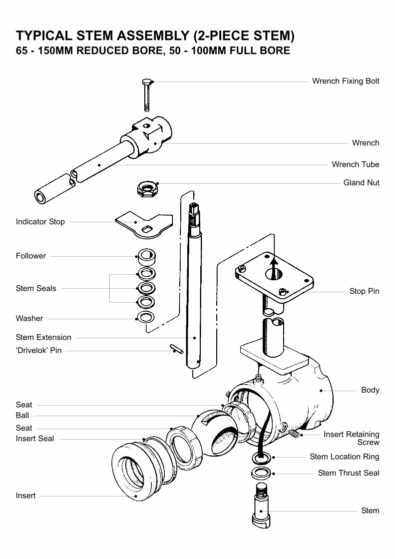
6.0 Platform / extension integral with valve body, with two-piece stem.6.1 Disassembly of the extended stem assembly: Remove the wrench assembly, followed by the locking
clip, gland nut, disc springs, stop plate and gland (as appropriate to the valve size & series). Push the stem down into the valve body cavity and drive out the extension 'Drivelok' pin. The lower stem portion can now be unscrewed and removed from within the cavity and the top portion withdrawn through the top of the housing. Remove the remaining gland components and discard the gland packing and thrust seal. The two sections of the stem must be stored together and remain as a matched pair.
6.2 Rebuilding: Fit the thrust seal to the lower stem portion and position into the stem bore through the valve cavity. Insert the upper stem portion through the top of the housing and screw the two sections together until the pin holes align, then refit the 'Drivelok' pin. To the top of the stem, fit the gland components, stop plate and gland nut as appropriate to the valve size and series (if disc springs are incorporated they should be fitted with outer edges touching). Tighten the nut to the recommended stem assembly torque (see chart following O-Ring Stem Build Section). Over tightening will only reduce the life of the stem assembly. Fit the locking clip over the gland nut (if appropriate to valve size and series).
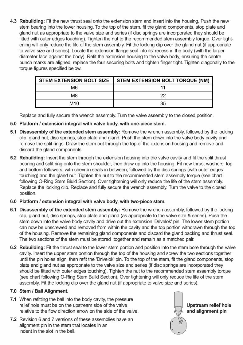
7.0 Stem / Ball Alignment.7.1 When refitting the ball into the body cavity, the pressure
relief hole must be on the upstream side of the valve Upstream relief holerelative to the flow direction arrow on the side of the valve. and alignment pin
7.2 Revision 6 and 7 versions of these assemblies have an alignment pin in the stem that locates in an indent in the slot in the ball.
STEM EXTENSION BOLT SIZEM6M8
1122
M10 35
STEM EXTENSION BOLT TORQUE (NM)

TYPICAL 3-PIECE VALVE WITH EXTENDED STEMASSEMBLY - R6 & R7 VERSIONS
Wrench
Wrench Sleeve
Follower (Top)
Chevron Seal
Follower (Bottom)
Thrust Bearing
Disc Spring
Wrench/Gland Nut
Gland Nut Locking Clip
Gland/Wrench Nut
Lock Washer
Stem
Split Thrust BearingSplit Ring
R6 Design

TYPICAL FLANGED VALVE WITH BOLT-ON EXTENDEDSTEM ASSEMBLY
Wrench
Wrench Sleeve
GlandDisc Spring
Wrench/Gland Nut
Extension Platform
Spring Washer
Gland Nut Locking Clip
Stem Thrust Seal
Stem BearingFlange Seal
Extension PlatformScrew
Gland Packing
Stem
Stop Pin
Wrench/Gland Nut
UP TO AND INCLUDING 50MM REDUCED BORE,40MM FULL BORE
65MM REDUCED BORE,50MM FULL BORE
AND LARGER

TYPICAL EXTENDED STEM ASSEMBLY - R5 VERSION(2-PIECE STEM)15 - 50MM REDUCED BORE, 15 - 40MM FULL BORE
Wrench Sleeve
Gland Packing
Disc Spring
Gland Nut
Stem Extension
Stop Plate
Extension Platform
Stem Extension Flange
Stem Thrust Bearing
Extension ‘Drivelok’ Pin
Packing Washer
Gland
Stem Lockwasher/Wrench Nut
Stem Extension Housing
Stem Tang
TYPICAL STEM ASSEMBLY (2-PIECE STEM)65 - 150MM REDUCED BORE, 50 - 100MM FULL BORE
Indicator Stop
Washer
Follower
Insert
Insert RetainingScrew
Stem Seals
Stem
Stop Pin
Gland Nut
Wrench Tube
Wrench
Wrench Fixing Bolt
Stem Thrust Seal
Stem Location Ring
Body
Insert SealSeatBallSeat
Stem Extension‘Drivelok’ Pin
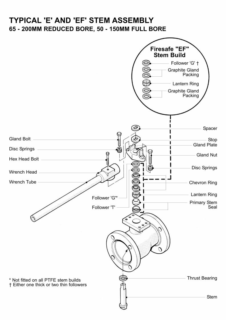
Envirosafe Valves: 'E' & 'EF' SeriesThis section contains only details of Envirosafe valve stem assemblies.For all other valve maintenance, disassembly, rebuilding, health and safety instructions etc,please refer to the relevant I.O.M. for the particular series of valve.
Maintenance, Disassembly, Rebuilding:1.0 General: Before rebuilding, ensure that the repair kit and /or components used are suitable for the
valve requirement. All components not replaced by items in the repair kit should be thoroughly cleaned (using a suitable degreasing agent, and wire wool for hard deposits) and checked for signs of corrosion, erosion or damage and be replaced if necessary.Cleanliness is essential for long valve life.
2.0 Stem Leakage:2.1 Due to the design of the Envirosafe Valve and with the installation of sensing devices
(i.e. pressure indicators or leak detection equipment) to the purge ports, advanced warning of leakage can be obtained as soon as the primary seal begins to pass media.
2.2 Envirosafe valves are available with five purge port configurations:'PP0': No purge ports (Inter-stage leakage monitoring not applicable).'PP1': One purge port - BSPT.'PP2': Two purge ports - BSPT. 'PP3': One purge port - NPT. 'PP4': Two purge ports - NPT.
2.3 Once a leak has been detected adjustment to the gland assembly can be carried out via the gland bolts retaining the gland plate. However it should be noted that the secondary seal would maintain valve integrity preventing any emission to atmosphere.
2.4 Primary Stem Seal Leakage: If leakage is detected at the purge port tighten the gland bolts evenly to the specified torque. Over tightening will only reduce the life of the stem assembly. If leakage persists, it will be necessary to dismantle the valve and replace the damaged seals.
2.5 Secondary Stem Seal Leakage: If leakage is detected to atmosphere past both the primary and secondary seals follow the same procedure as 2.4 above.
3.0 Stem Assembly Dismantling:3.1 15mm to 65mm Reduced Bore,15mm - 50mm Full Bore Valves:
a) Remove the wrench (one-piece design) by removing the two retaining set screws, followed by the gland bolts, disc springs, gland plate and follower(s).
b) Push the stem down into the body cavity and from the inner end, remove the split ring and split thrust bearing. Now withdraw the stem through the top of the body (care must be taken to avoid damaging the sealing surfaces of the packing chamber). This may require considerable force - the stem flats can be clamped in a vice utilising soft jaws to aid removal.
c) All of the gland packings etc will be withdrawn with the stem as the stem thrust seal face is a larger diameter than the internal bores of the packings. All soft seals should be discarded.
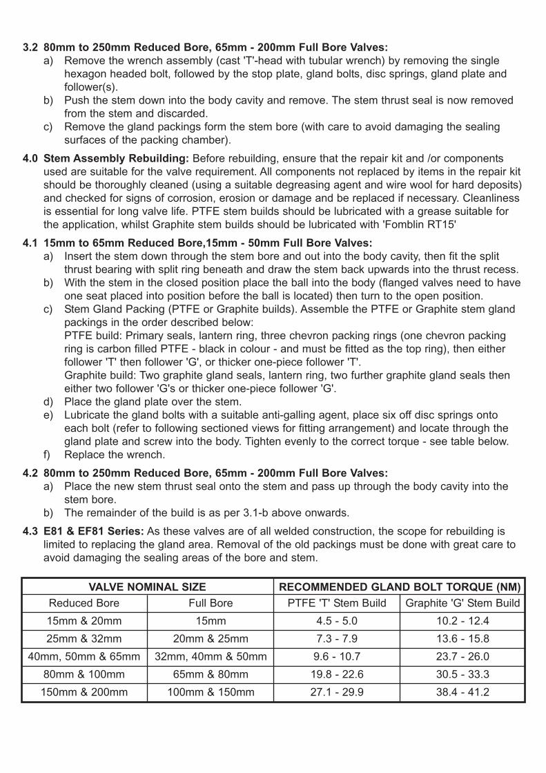
3.2 80mm to 250mm Reduced Bore, 65mm - 200mm Full Bore Valves:a) Remove the wrench assembly (cast 'T'-head with tubular wrench) by removing the single
hexagon headed bolt, followed by the stop plate, gland bolts, disc springs, gland plate and follower(s).
b) Push the stem down into the body cavity and remove. The stem thrust seal is now removed from the stem and discarded.
c) Remove the gland packings form the stem bore (with care to avoid damaging the sealing surfaces of the packing chamber).
4.0 Stem Assembly Rebuilding: Before rebuilding, ensure that the repair kit and /or components used are suitable for the valve requirement. All components not replaced by items in the repair kitshould be thoroughly cleaned (using a suitable degreasing agent and wire wool for hard deposits)and checked for signs of corrosion, erosion or damage and be replaced if necessary. Cleanliness is essential for long valve life. PTFE stem builds should be lubricated with a grease suitable for the application, whilst Graphite stem builds should be lubricated with 'Fomblin RT15'
4.1 15mm to 65mm Reduced Bore,15mm - 50mm Full Bore Valves:a) Insert the stem down through the stem bore and out into the body cavity, then fit the split
thrust bearing with split ring beneath and draw the stem back upwards into the thrust recess.b) With the stem in the closed position place the ball into the body (flanged valves need to have
one seat placed into position before the ball is located) then turn to the open position.c) Stem Gland Packing (PTFE or Graphite builds). Assemble the PTFE or Graphite stem gland
packings in the order described below:PTFE build: Primary seals, lantern ring, three chevron packing rings (one chevron packing ring is carbon filled PTFE - black in colour - and must be fitted as the top ring), then either follower 'T' then follower 'G', or thicker one-piece follower 'T'.Graphite build: Two graphite gland seals, lantern ring, two further graphite gland seals then either two follower 'G's or thicker one-piece follower 'G'.
d) Place the gland plate over the stem.e) Lubricate the gland bolts with a suitable anti-galling agent, place six off disc springs onto
each bolt (refer to following sectioned views for fitting arrangement) and locate through the gland plate and screw into the body. Tighten evenly to the correct torque - see table below.
f) Replace the wrench.4.2 80mm to 250mm Reduced Bore, 65mm - 200mm Full Bore Valves:
a) Place the new stem thrust seal onto the stem and pass up through the body cavity into the stem bore.
b) The remainder of the build is as per 3.1-b above onwards.4.3 E81 & EF81 Series: As these valves are of all welded construction, the scope for rebuilding is
limited to replacing the gland area. Removal of the old packings must be done with great care to avoid damaging the sealing areas of the bore and stem.
Reduced Bore PTFE 'T' Stem BuildFull Bore Graphite 'G' Stem Build15mm & 20mm 4.5 - 5.015mm 10.2 - 12.425mm & 32mm 7.3 - 7.920mm & 25mm 13.6 - 15.8
40mm, 50mm & 65mm 9.6 - 10.732mm, 40mm & 50mm 23.7 - 26.080mm & 100mm 19.8 - 22.665mm & 80mm 30.5 - 33.3
150mm & 200mm 27.1 - 29.9100mm & 150mm 38.4 - 41.2
VALVE NOMINAL SIZE RECOMMENDED GLAND BOLT TORQUE (NM)

Follower 'T'ChevronPackingRingsPrimarySeals
Follower 'T'ChevronPackingRingsPrimarySeals
GraphitePacking
Rings
GraphitePacking
Rings
SplitRing
Split Thrustbearing
Stem
Lantern Ring
Follower 'G'
GlandPlate
Disc Spring
GlandBolt
Split ThrustbearingStem
Lantern Ring
Follower 'G'
GlandPlate
Disc Spring
GlandBolt
STEM BUILDS ALL SIZES
VALVE SIZES: 15 - 50MM REDUCED BORE, 15 - 40MM FULL BORE
VALVE SIZES: 65 - 200MM REDUCED BORE, 50 - 150MM FULL BORE
'T' Packing Detail 'G' Packing Detail
'T' Packing Detail 'G' Packing Detail

TYPICAL 'E' AND 'EF' STEM ASSEMBLY15 - 50MM REDUCED BORE, 15 - 40MM FULL BORE
Wrench
Stem
Disc Springs
Disc Springs
Follower 'T'
Chevron Ring
Wrench/Gland Nut
Firesafe "EF" Stem Build
Wrench Screw
Thrust BearingSplit Ring
Lantern Ring
Primary StemSeal
Follower 'G' †
Lantern RingGraphite Gland
Packing
Graphite GlandPacking
* Not fitted on all PTFE stem builds† Either one thick or two thin followers
Gland Plate
Follower 'G'*
TYPICAL 'E' AND 'EF' STEM ASSEMBLY65 - 200MM REDUCED BORE, 50 - 150MM FULL BORE
Wrench Tube
Gland Bolt
Disc Springs
Chevron Ring
Spacer
Firesafe "EF" Stem Build
Lantern Ring
Primary StemSeal
Follower 'G' †
Lantern RingGraphite Gland
Packing
Graphite GlandPacking
* Not fitted on all PTFE stem builds† Either one thick or two thin followers
Wrench Head
Follower 'G'*
Disc Springs
Hex Head Bolt
StopGland Plate
Gland Nut
Stem
Thrust Bearing
Follower 'T'
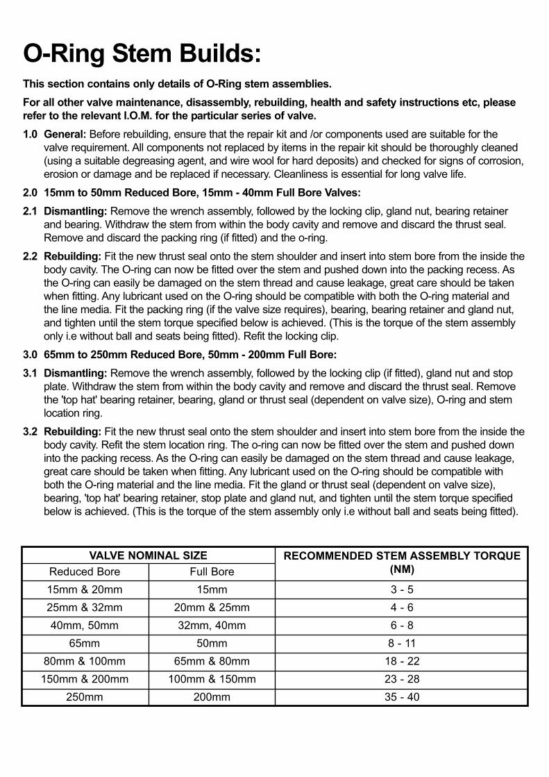
O-Ring Stem Builds:This section contains only details of O-Ring stem assemblies.For all other valve maintenance, disassembly, rebuilding, health and safety instructions etc, pleaserefer to the relevant I.O.M. for the particular series of valve.1.0 General: Before rebuilding, ensure that the repair kit and /or components used are suitable for the
valve requirement. All components not replaced by items in the repair kit should be thoroughly cleaned (using a suitable degreasing agent, and wire wool for hard deposits) and checked for signs of corrosion,erosion or damage and be replaced if necessary. Cleanliness is essential for long valve life.
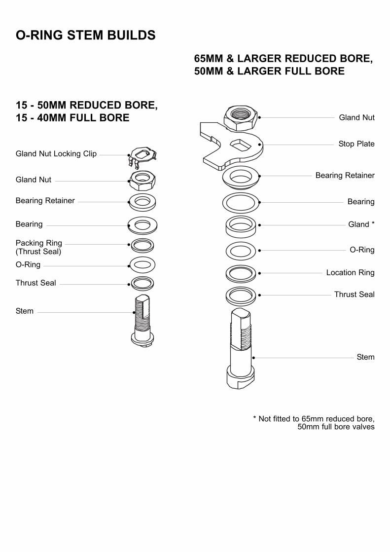
2.0 15mm to 50mm Reduced Bore, 15mm - 40mm Full Bore Valves:2.1 Dismantling: Remove the wrench assembly, followed by the locking clip, gland nut, bearing retainer
and bearing. Withdraw the stem from within the body cavity and remove and discard the thrust seal. Remove and discard the packing ring (if fitted) and the o-ring.
2.2 Rebuilding: Fit the new thrust seal onto the stem shoulder and insert into stem bore from the inside thebody cavity. The O-ring can now be fitted over the stem and pushed down into the packing recess. As the O-ring can easily be damaged on the stem thread and cause leakage, great care should be taken when fitting. Any lubricant used on the O-ring should be compatible with both the O-ring material and the line media. Fit the packing ring (if the valve size requires), bearing, bearing retainer and gland nut, and tighten until the stem torque specified below is achieved. (This is the torque of the stem assembly only i.e without ball and seats being fitted). Refit the locking clip.
3.0 65mm to 250mm Reduced Bore, 50mm - 200mm Full Bore:3.1 Dismantling: Remove the wrench assembly, followed by the locking clip (if fitted), gland nut and stop
plate. Withdraw the stem from within the body cavity and remove and discard the thrust seal. Remove the 'top hat' bearing retainer, bearing, gland or thrust seal (dependent on valve size), O-ring and stem location ring.
3.2 Rebuilding: Fit the new thrust seal onto the stem shoulder and insert into stem bore from the inside thebody cavity. Refit the stem location ring. The o-ring can now be fitted over the stem and pushed down into the packing recess. As the O-ring can easily be damaged on the stem thread and cause leakage, great care should be taken when fitting. Any lubricant used on the O-ring should be compatible with both the O-ring material and the line media. Fit the gland or thrust seal (dependent on valve size), bearing, 'top hat' bearing retainer, stop plate and gland nut, and tighten until the stem torque specified below is achieved. (This is the torque of the stem assembly only i.e without ball and seats being fitted).
Reduced Bore Full Bore15mm & 20mm 3 - 515mm25mm & 32mm 4 - 620mm & 25mm40mm, 50mm 6 - 832mm, 40mm
80mm & 100mm 18 - 2265mm & 80mm150mm & 200mm 23 - 28100mm & 150mm
VALVE NOMINAL SIZE RECOMMENDED STEM ASSEMBLY TORQUE(NM)
250mm 35 - 40200mm
65mm 8 - 1150mm
O-RING STEM BUILDS
Gland Nut Locking Clip
Gland Nut15 - 50MM REDUCED BORE, 15 - 40MM FULL BORE
Stem
Gland Nut
Bearing Retainer
Bearing
Packing Ring(Thrust Seal)O-Ring
Thrust Seal
Stem
Stop Plate
Bearing Retainer
Bearing
Gland *
O-Ring
Location Ring
Thrust Seal
65MM & LARGER REDUCED BORE, 50MM & LARGER FULL BORE
* Not fitted to 65mm reduced bore,50mm full bore valves

Published and Printed by Worcester Controls © Copyright Worcester Controls PB STEM IOM Iss. 8/02
TM
Worcester ControlsBurrell Road, Haywards Heath, West Sussex RH16 1TL, England.Telephone: +44 (0)1444 314400 Telefax: +44(0)1444 314401Website: www.worcestercontrols.co.ukTM indicates a trade mark of Worcester ControlsInformation given in this leaflet is made in good faith and based upon specific testing but does not, however constitute a guarantee.
A Flowserve Company