WoodWorks Connection Design Workshop...WoodWorks Connection Design Workshop Bernhard Gafner, P.Eng,...
105
WoodWorks Connection Design Workshop Bernhard Gafner, P.Eng, MIStructE, Dipl. Ing. FH/STV [email protected] Adam Gerber, M.A.Sc. [email protected] Disclaimer: This presentation was developed by a third party and is not funded by WoodWorks or the Softwood Lumber Board.
Transcript of WoodWorks Connection Design Workshop...WoodWorks Connection Design Workshop Bernhard Gafner, P.Eng,...

WoodWorksConnection Design
Workshop
Bernhard Gafner, P.Eng, MIStructE, Dipl. Ing. FH/STV
Adam Gerber, M.A.Sc.
Disclaimer: This presentation was developed by a third partyand is not funded by WoodWorks or the Softwood Lumber Board.

“The Wood Products Council”is a Registered Provider with The American Institute of Architects Continuing Education Systems (AIA/CES), Provider #G516.
Credit(s) earned on completion of this course will be reported to AIA CES for AIA members. Certificates of Completion for both AIA members and non-AIA members are available upon request.
This course is registered with AIA CES for continuing professional education. As such, it does not include content that may be deemed or construed to be an approval or endorsement by the AIA of any material of construction or any method or manner of handling, using, distributing, or dealing in any material or product.__________________________________
Questions related to specific materials, methods, and services will be addressed at the conclusion of this presentation.
For engineers new to mass timber design, connections can pose a particular challenge. This course focuses on connection design principles and analysis techniques unique to mass timber products such as cross-laminated timber, glued-laminated timber and nail-laminated timber. The session will focus on design options for connection solutions ranging from commodity fasteners, pre-engineered wood products and custom-designed connections. Discussion will also include a review of timber mechanics and load transfer, as well as considerations such as tolerances, fabrication, durability, fire and shrinkage that are relevant to structural design.
Description

1. Review the timber mechanics that are relevant to mass timber design including, grain orientation and dimensional stability and define how loads are transferred in timber connections.
2. Consider practical aspects of design that are not traditionally in the scope of a structural design for other materials but may be relevant for mass timber such as tolerances, fabrication, durability, fire, and shrinkage.
3. Explore connection solutions available including commodity fasteners, pre-engineered products and custom designed connections.
4. Learn about cutting edge connection technologies and resources for learning more.
Learning Objectives

Agenda
1. Timber Mechanics
2. Principles of Connection Design
3. Practical Considerations
4. Design Solutions
5. Next Generation of Connections

3 Things to remember
1. NEVER use lag screws again
2. Small Ø are better than large (t/d=5)
3. Get to know the fabricators / installers
First - Lets Build some Context…

Context…
Building context is
collecting the dots
…leads to Design
Design is
connecting the
dots

Where are we at?

But we have this

1. Timber Mechanics

1.1 How it’s Built

1.1 How it’s Built
1. Growth rings create a cylindrical structure, longitudinal arrangements of fibers
2. Properties vary between parallel/perpendicular directions and between the transverse directions

1.2 Moisture
Equilibrium Moisture Content (EMC):
MC that is in equilibrium with the environment
Dry service conditions: average EMC over a year is 15% or less

1.3 Shrinkage / Swelling
0.25% / 1%

2. Principles of Connection Design

“Connection design will depend on various factors: nature of the
forces and their magnitude, practicality, production,
environmental conditions, aesthetics and cost”

2.1 Environment

2.2 Connection Stiffness
1. Glued Connection
2. Tight Fit Dowel / Bolt Φ = 14 mm
3. Through Bolts Φ = 14 mm
4. Truss Plate 10’000 mm2
5. Nail Φ = 4.4 mm

2.3 Bolt vs. Tight Fit Dowels

2.3 Bolt vs. Tight Fit Dowels
Tight Fit Dowel with Plug
Tight Fit Dowel flush
Tight Fit Dowel with projection
Through Bolt
Tight Fit Bolt

2.3 Bolt vs. Tight Fit Dowels
Size of hole in Wood Size of hole in Steel Use of Connection
Tight Fit
Dowel/Bolt
Same size as pin/bolt
diameter
Up to 1/32” larger
than pin/bolt
diameter
Typically used for engineered connections
without additional load transfers (ie. w/o
bearing plates for example).
Through
Bolt
Up to 1/16” larger
than bolt diameter
Up to 1/16” larger
than pin/bolt
diameter
Typically used in connections where the
bolt serves as a positioning aid.
Traditional heavy timber buildings may
also feature such a connection.
This type of connection should be
avoided in heavily loaded connections or
if part of the SFRS.

2.3 Bolt vs. Tight Fit Dowels
!! NDS HAS 75% CAP FOR DRIFT PINS…
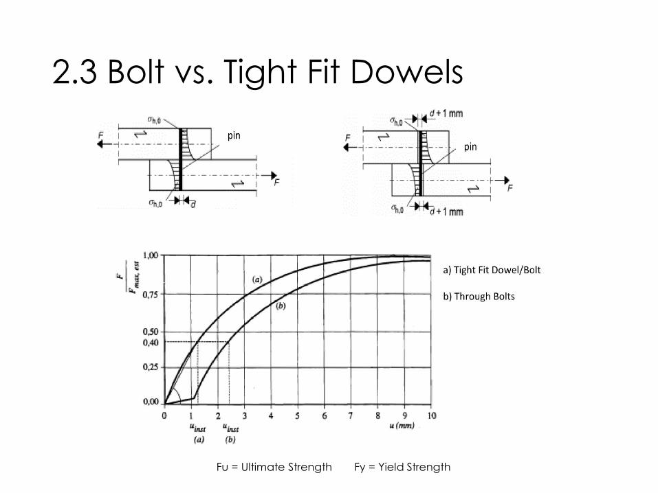
2.3 Bolt vs. Tight Fit Dowels
Fu = Ultimate Strength Fy = Yield Strength
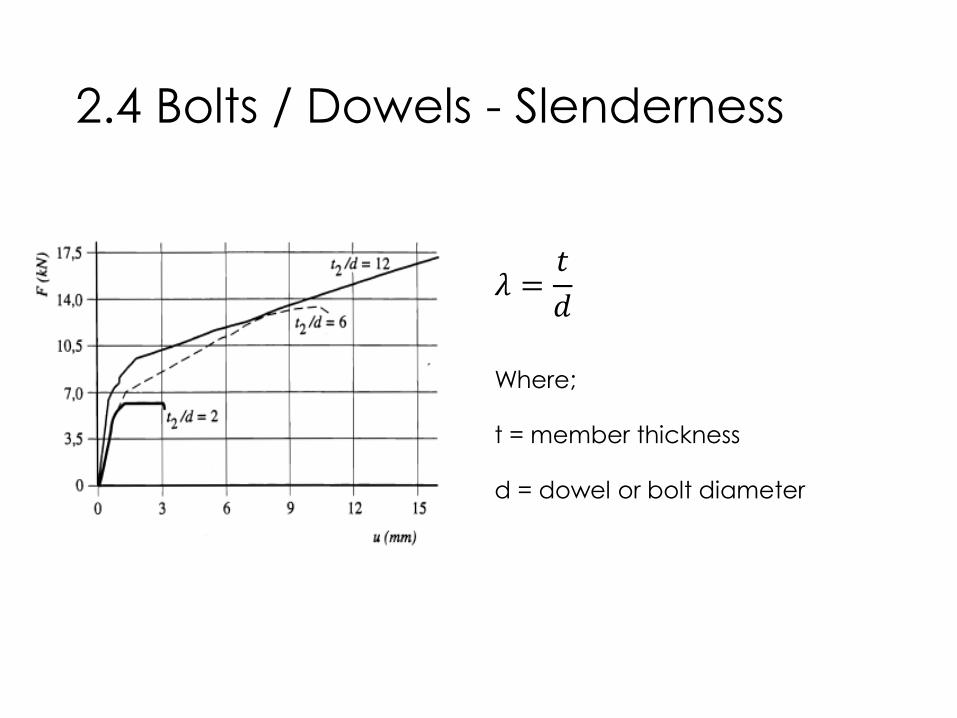
2.4 Bolts / Dowels - Slenderness
𝜆 =𝑡
𝑑
Where;
t = member thickness
d = dowel or bolt diameter

2.5 Bolts / Dowels – Failure Mode

2.5 Bolts / Dowels – Failure Mode

2.6 Bolts / Dowels – Seismic Design
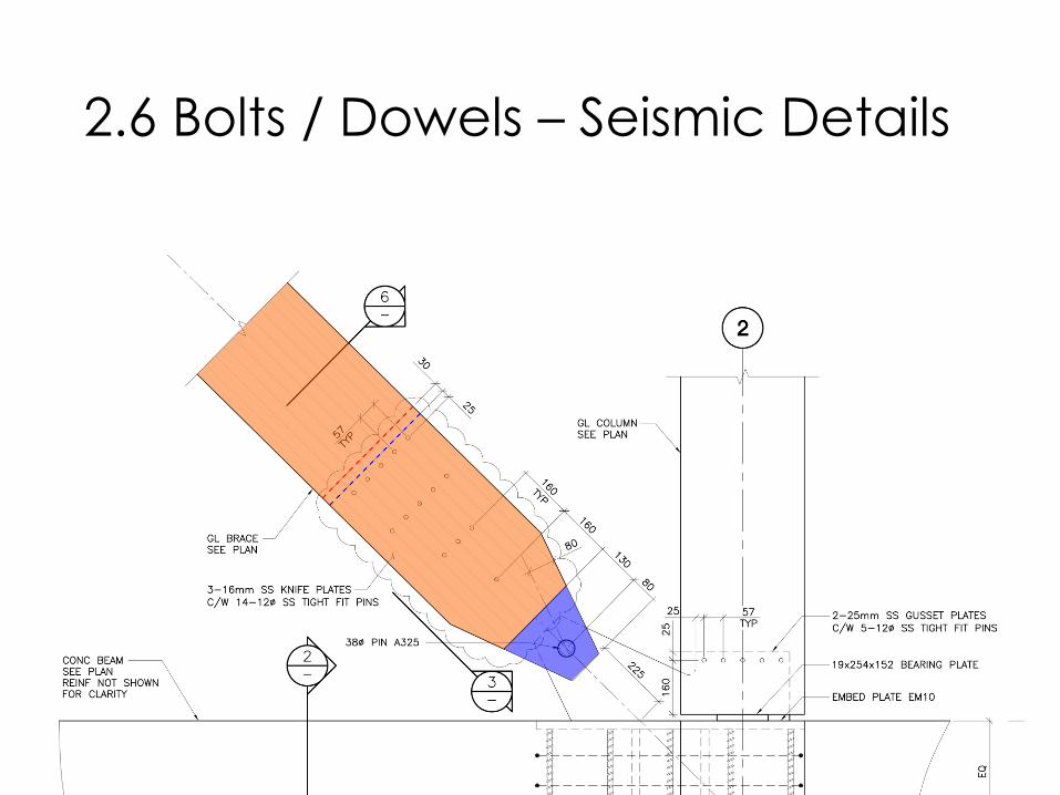
2.6 Bolts / Dowels – Seismic Details

2.7 How to Achieve Modus 3?
• The slenderness limit λy,1 in order to achieve Mode 2 is described as:
• λy,1 = 2 ∗Mu
fh∗d 3
• Or a minimum wood thickness for a given fastener per:
• ty,1 = 2 ∗Mufh∗d
• The slenderness limit λy,2 in order to achieve Mode 3 is described as:
• λy,2 = 4 ∗Mu
fh∗d 3
• Similarly, this can be represented as a minimum wood thickness for a given fastener per:
• ty,2 = 4 ∗Mufh∗d
• Where;
• Mu = Plastic bending resistance of the dowel/bolt
in [N-mm]
fh = Characteristic embedment strength [N/mm2]
d = Dowel/bolt diameter in [mm]
• Mu = 0.26 * fu * d 2.7 [N-mm]
fh,0,k = 0.082 (1- 0.01 d) ρk [N/mm2
fh,90,k = fh,0,k / (1.35 + 0.015 d) [N/mm2]
fh,α,k = Embedment strength at any angle to grain;
interpolate between fh,0,k and fh,90,k in [N/mm2
ρk = Characteristic density of wood in [kg/m3]
• For design purposes, ty,1 should be considered the minimum member thickness used (Mode 2), where ty,2should be considered the ideal thickness (Mode 3).
• For connections with multiple knife plates, the minimum member thickness should be taken based on Mode 3.
Reference: Load-carrying behaviour of steel-to-timber dowel connections; Adrian Mischler, Helmut Prion,
Frank Lam; http://timber.ce.wsu.edu/Resources/papers/2-4-1.pdf

2.7 How to Achieve Modus 3?
In order to obtain the characteristic density, the mean oven-dry relative density can be multiplied with a factor of approximately 0.84.
Species Mean Oven-Dry Relative
Density
(i.e. oven dry specific gravity)
Characteristic Density at
12%MC
(i.e. 5th percentile)
D.Fir-Larch (sawn lumber and
Glulam)0.49 410 Kg/m3
Hem-Fir (sawn lumber and
Glulam)0.46 385 Kg/m3
Spruce-Pine-Fir (sawn Lumber) 0.42 350 Kg/m3
Spruce-Pine (Glulam) 0.44 370 Kg/m3
Northern Species 0.35 300 Kg/m3
Black Spruce (Glulam) 0.56 470 Kg/m3
Parallam (PSL) 0.50 420 Kg/m3
Laminated Strand Lumber (LSL) 0.50 420 Kg/m3
Laminated Veneer Lumber
(LVL)0.50 420 Kg/m3

2.7 How to Achieve Modus 3?

2.7 How to Achieve Modus 3?

2.7 How to Achieve Modus 3?
Previous slides based on:Spacing between bolts in a row:4 x ØEnd distance:10 x Ø
NDS based on:Spacing between bolts in a row:4 x ØEnd distance:7 x Ø

2.8 Mild vs. Stainless Steel
SAE J429 Grade 1; Fu = 60ksi (410N/mm2), Fy = 36ksi (240N/mm2), Ratio =1.7 min Elongation 18%
304 Stainless Steel; Fu = 85ksi (580N/mm2), Fy = 36ksi (240N/mm2), Ratio =2.4Elongation 40%
Galvanic Corrosion?!

2.9 Tension Perpendicular

2.9 Tension Perpendicular

2.9 Tension Perpendicular
In general, if a/h ≥ 0.7, the effect of tension perpendicular can be ignored. This should be the preferred approach to any connection

2.9 Tension Perpendicular
Ft,90,d = [1-3 * (a/h)2 + 2 * (a/h)3] * Fv,Ed
with:
Ft,90,d = design tension perpendicular to grainFv,Ed = design connection force
The reinforcing is to be designed for Ft,90,d.
Embedment length for design lad = min {lad,c; lad,t}.
lad,t should extend at least up to 75% of the beam height.
Reinforcement should be placed within an area based on 30° measured from the top of the connection.

2.9 Tension Perpendicular

2.9 Tension Perpendicular

2.10 Carpenter Connections
Carpenter connections often economical
Combine with modern fastener

2.10 Carpenter Connections

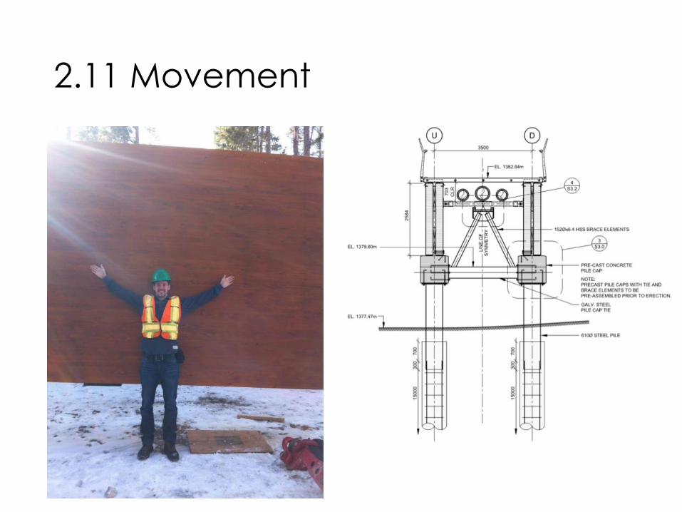
2.11 Movement
Be realistic about actual fluctuation of EMC
It takes quite a while for larger cross sections to equalize throughout the cross section
shrinkage
swell ing
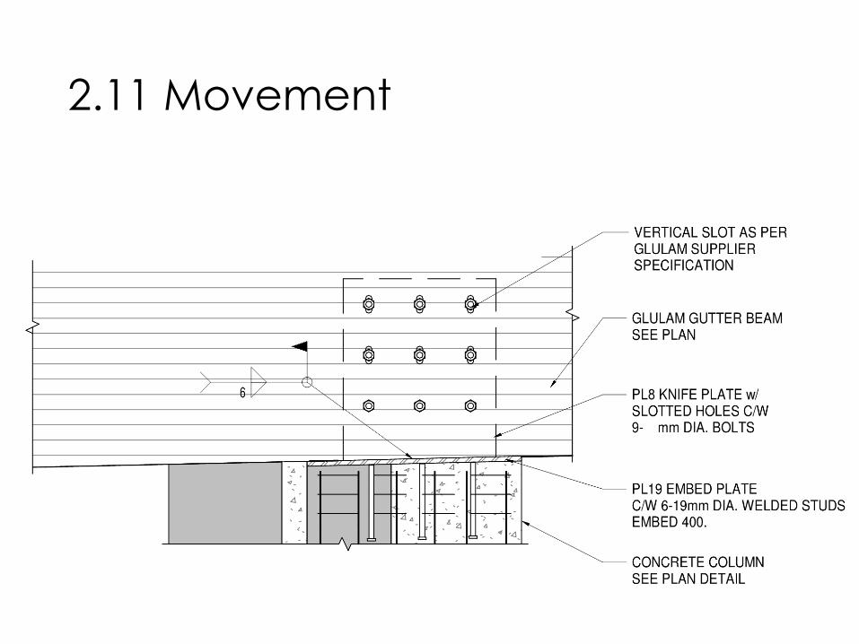
2.11 Movement
2.11 Movement

2.11 Movement

2.12 Summary
• Direct load path
• Respect Wood Movement (and design for it!)
• Bolts / Dowels to have ductile failure modes
• Careful with tension perpendicular
• Avoid horizontal wood in the vertical load path
• Old school bearing type connections often economical
• Design with fabrication and installation in mind next chapter

3. Practical Considerations

3.1 Equipment
• Hand Tools

3.1 Equipment
• CNC

3.2 Installers

3.3 Overview
Practical Considerations for Connection Designs
Origin of Issue Where to address the Issue
De
sig
n
Fa
bric
atio
n
Tra
nsp
ort
atio
n
Inst
alla
tio
n
Use
De
sig
n
Fa
bric
atio
n
Tra
nsp
ort
atio
n
Inst
alla
tio
n
Use
Supply Capabilities
CNC machining vs Hand-framing of wood members
x x
Supply Capabilities
Welding / machining of custom steel pieces
x x x
Shrinkage Movement (or restricted movement) of wood due to fluctuation of moisture content
x x
Tolerances Missing tolerance level in standardsx x x
Tolerances Member size not as per specs, assembly of members doesn’t fit
x x x x
Tolerances Interface to other materials (steel and concrete) doesn’t fit. Steel and concrete have much larger tolerances
x x x x
Fire Resistance Charring of wood, reduction of cross section, heat transfer
x x x x
Fire Resistance Exposed connectorsx x x x

3.3 Overview
Practical Considerations for Connection Designs
Origin of Issue Where to address the Issue
De
sig
n
Fa
bric
atio
n
Tra
nsp
ort
atio
n
Inst
alla
tio
n
Use
De
sig
n
Fa
bric
atio
n
Tra
nsp
ort
atio
n
Inst
alla
tio
n
Use
Local Workforce
Installation strategy needs to respect labor skill sets available.
x x
Site Conditions Crane type and locations may impact member length and require add'l splices.
x x x
Speed of installation
Maximize site production, limited crane time available
x x
Speed of installation
Connection typesx x x
AHJ AHJ is not familiar with the type of construction
x x
AHJ AHJ does not facilitate the use of alternate connectors
x x
Drift Compatibility
Connections need to accommodate lateral movement
x x x x
Detail Complexity
Multiple members framing coming together
x x

4. Design Solutions

4.1 Commodity (NDS Dowel-Type)4.1.0 General – Resistance Values

4.1 Commodity (NDS Dowel-Type)4.1.1 Standard Hex Bolts
Applications Pros Cons
• Direct beam to beam connections (in shear)
• Beam to beam or beam to column connections via knife or side plates
• Nominal connectors for plate saddles/bearing connections
• Readily Available• Skilled trades not required for
installation• Can keep bolt heads exposed for
architecturally expressive exposed old-school heavy timber connections
• Can be used for timber connection to any material (concrete, steel, masonry)
• Connections are naturally exposed• Both sides of connection must be
accessible • Bolt head/nut and washer must be
perpendicular to connected surfaces (or shimmed or notched/recessed to suit)

Remember….?!
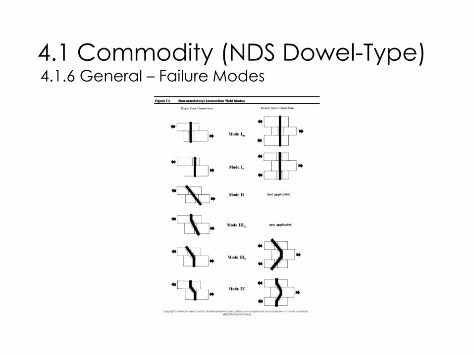
4.1 Commodity (NDS Dowel-Type)4.1.6 General – Failure Modes

4.1 Commodity (NDS Dowel-Type)4.1.6 General – Failure Modes

4.1 Commodity (NDS Dowel-Type)4.1.6 General – 6-3/4” D.Fir-L Glulam
Reference: http://www.awc.org/codes-standards/calculators-software/connectioncalc

4.1 Commodity (NDS Dowel-Type)4.1.2 Standard Hex Lag Screws
Applications Pros Cons
• Direct beam to beam connections (in shear)
• Beam to beam or beam to column connections via side plates
• Nominal connectors for plate saddles/bearing connections where only one side is accessible
• Readily Available• Can keep bolt heads exposed for
architecturally expressive old-school exposed heavy timber connections
• Only one side of connection needs to be accessible
• May be loaded in tension/withdrawal (but please avoid it)
• Very time consuming to install (skill needed)
• Connections are naturally exposed• Lag screw head must be
perpendicular to side member surface

4.1 Commodity (NDS Dowel-Type)4.1.3 Standard Wood Screws
Applications Pros Cons
• Light wood frame connections (side members <1 ½”)
• Loading permitted in shear and tension/withdrawal
• Readily Available• Relatively quick to install with a
power drill• Skilled trades not required• Variable head sizes and shapes –
can be flush or recessed if required• Small heads = low connection
visibility• May be installed at an angle to the
surface (with reduction factor) • Only one side of connection needs
to be exposed• Predrilling not required
• Design diameter varies. Important to clearly specify screws.
• Relatively short standard lengths available
• Small resistances

4.1 Commodity (NDS Dowel-Type)4.1.4 Common, Box, & Sinker Steel Wire Nails
Applications Pros Cons
• Light wood frame connections (side members <1 ½”)
• Shearwalls and diaphragms
• Readily Available• Quick to install with a nail gun• Skilled trades not required• Flush or (minimally) recessed heads• May be installed at an angle to the
surface (with reduction factor) • Small heads = low connection
visibility• Only one side of connection needs
to be exposed
• Low capacity per fastener• Loading permitted in shear only• Small resistances

4.2 Pre-Engineered / Proprietary
4.2.1 Screws
Lag Screws Self Tapping Screw

4.2 Pre-Engineered / Proprietary
4.2.1.1 Partially Threaded Screws
Partially threaded screws are the most common used screws. The thread extents are only over a certain length of the shaft, depending on the total length of the screws
These screws are mainly used in shear applications.

4.2 Pre-Engineered / Proprietary
4.2.1.2 Fully Threaded Screws
Fully threaded screws are mostly used in connections with tension forces to be transferred. The thread extents are over the full length of the shaft, regardless of the total length of the screws. After a certain length of screw, the actual steel tension capacity of the screw is the governing factor.
These screws are mainly used in tension and compression applications, to reinforce beams and for butt joints.

4.2 Pre-Engineered / Proprietary
4.2.1.3 Screw Heads

4.2 Pre-Engineered / Proprietary
4.2.1.3 Screw Heads

4.2 Pre-Engineered / Proprietary
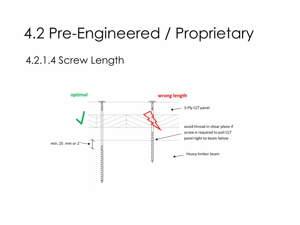
4.2.1.4 Screw Length
For screws in shear, the shear plane should be in the shank and not in the threaded portion of the screw. Otherwise the members wont close during the installation .
If fully threaded screws are used, consider combining them with partially threaded screws
Careful with diameter used for the design!
4.2 Pre-Engineered / Proprietary
4.2.1.4 Screw Length

4.2 Pre-Engineered / Proprietary
4.2.1.5 Screw diameter

4.2 Pre-Engineered / Proprietary
4.2.1.6 Tension Connections

4.2 Pre-Engineered / Proprietary
4.2.1.6 Tension Connections

4.2 Pre-Engineered / Proprietary
4.2.1.6 Tension Connections

4.2 Pre-Engineered / Proprietary
4.2.1.6 Tension Connections
Reference: Grazer Holzbau-Fachtagung 2007: Traglast von auf Zugbeanspruchten Schraubenverbindungen
mit Stahlblechen http://www.holzbauforschung.at/uploads/tx_sbdownloader/6GraHFT07_Tagungsband.pdf

4.2 Pre-Engineered / Proprietary
4.2.1.6 Tension Connections
Reference: Grazer Holzbau-Fachtagung 2007: Traglast von auf Zugbeanspruchten Schraubenverbindungen
mit Stahlblechen http://www.holzbauforschung.at/uploads/tx_sbdownloader/6GraHFT07_Tagungsband.pdf

4.2 Pre-Engineered / Proprietary
4.2.1.7 Tension vs Shear
Increase of resistance by ≈100%

4.2 Pre-Engineered / Proprietary
4.2.1.8 Spacing
Follow the approvals for spacings!
Group Factors….!? (nef = n0.9)

4.2 Pre-Engineered / Proprietary
4.2.1.9 Overview

4.2 Pre-Engineered / Proprietary
4.2.2 Brackets
(Simpson ABR 105) (RothoBlaas Titan)

4.2 Pre-Engineered / Proprietary
4.2.3 Hangers
(Simpson CJT1) (RothoBlaas AluMaxi)

4.2 Pre-Engineered / Proprietary
4.2.3 Hangers
(Knapp Megant)

4.2 Pre-Engineered / Proprietary
4.2.3 Hangers

4.2 Pre-Engineered / Proprietary
4.2.3 Hangers

4.2 Pre-Engineered / Proprietary
4.2.3 Hangers

4.2 Pre-Engineered / Proprietary
4.2.4 Overview

4.2 Pre-Engineered / Proprietary
4.2.4 Overview

4.3 Custom
• Screws in tension and compression take load
• Housing helps to set purlins
• Screws for tolerance
• Connection is protected from fire
4.3.1 Housing & Fully Threaded Screws

4.3 Custom
• Glued in rods (5/8”) in end of column
• Rods take shear only (typ.) and set as locator pulling assembly
• HSS tube with steel plate top and bottom
• Simple connection to steel plate – 4 sets
• Set and level steel piece first, prior to landing column
• Steel could be pre-attached to column, especially for column to column connection
• Steel to be intumescent painted or filled with concrete for fire protection
4.3.2 Column Base Connection

4.3 Custom
• Simple assembly using steel plate and fully threaded screws
• Steel plate in bending
• Fully threaded screws in tension and compression (if needed to prevent crushing), respectively
• Ensure screw in tension is long enough to avoid tension perpendicular (screw is grabbing), shear in panel vertical
• Steel plate to be attached in shop
• Steel plate could be notched into below to be top flush
• Additional screws needed to secure assembly
• Allows for tolerances
• Connection is protected from fire
• Gravity only
4.3.3 Top Bearing Plate

4.3 Custom
• Washer head screws to pull panel flush
• Nails to transfer in-plane shear loads
• Out of plane shear loads to be taken by washer head screw and plywood bending or provide pairs of fully threaded screws (high heads)
• ¾” plywood, 5 ½” side. 4’ plywood sheet will yield 8 strips with minimal waste
4.3.4 CLT to CLT Surface Spline

5. Next Generation

5.1 Adhesive Connections
5.1.1 Glued in Rods

5.1 Adhesive Connections
5.1.2 HSK

5.1 Adhesive Connections
5.1.3 TS3.0 – Glued Butt Joints
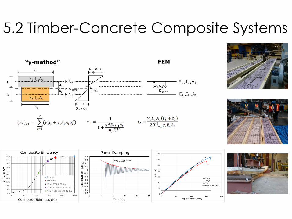
5.2 Timber-Concrete Composite Systems

5.2.1 TCC Connectors
5.2 Timber-Concrete Composite Systems

5.2.2 Panel Performance
5.2 Timber-Concrete Composite Systems

5.3.1 Post-tensioned Shear Walls
5.3 Post-Tensioned Systems

5.3.1 Post-tensioned Shear Walls
5.3 Post-Tensioned Systems

5.3.1 Post-tensioned glulam moment frames
5.3 Post-Tensioned Systems

Further Resources

• Load-carrying behaviour of steel-to-timber dowel connections; Adrian
Mischler, Helmut Prion, Frank Lam
http://timber.ce.wsu.edu/Resources/papers/2-4-1.pdf
• Grazer Holzbau-Fachtagung 2007: Traglast von auf Zugbeanspruchten
Schraubenverbindungen mit Stahlbleche; H. Krenn, G. Schickhofer
http://www.holzbauforschung.at/uploads/tx_sbdownloader/6GraHFT0
7_Tagungsband.pdf
• Self-tapping screws and threaded rods as reinforcement for structural
timber elements – A state-of-the-art report; Philipp Dietsch, Reinhard
Brandner
• EN 1995 design of timber structures (Eurocode 5)
• See also supplier specific documents and white papers

Questions?
This concludes the American Institute of Architects Continuing Education Course.
Bernhard Gafner Adam GerberASPECT Structural [email protected]@aspectengineers.com