Woodspec - A Guide to Designing, Detailing and … Final - Section D.pdfWoodspec - A Guide to...
28
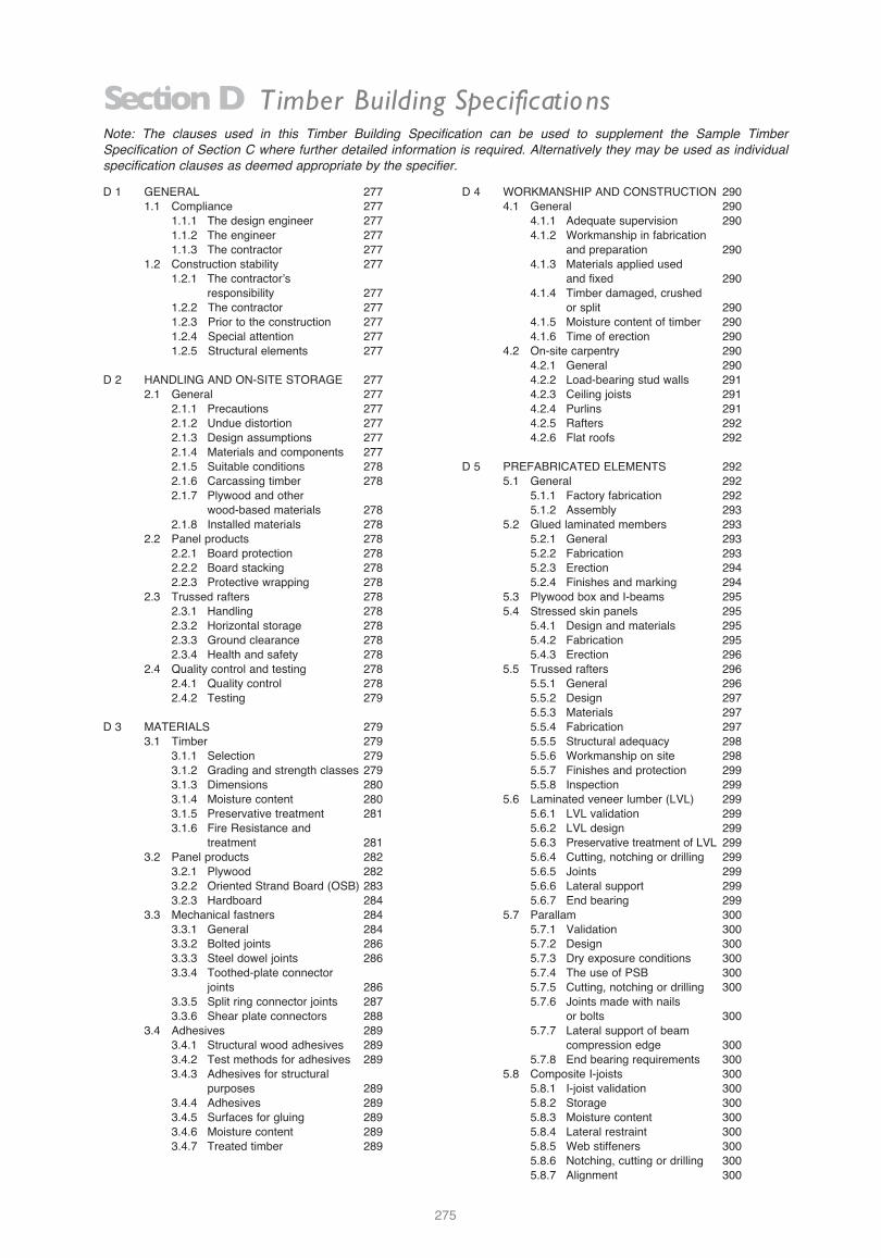
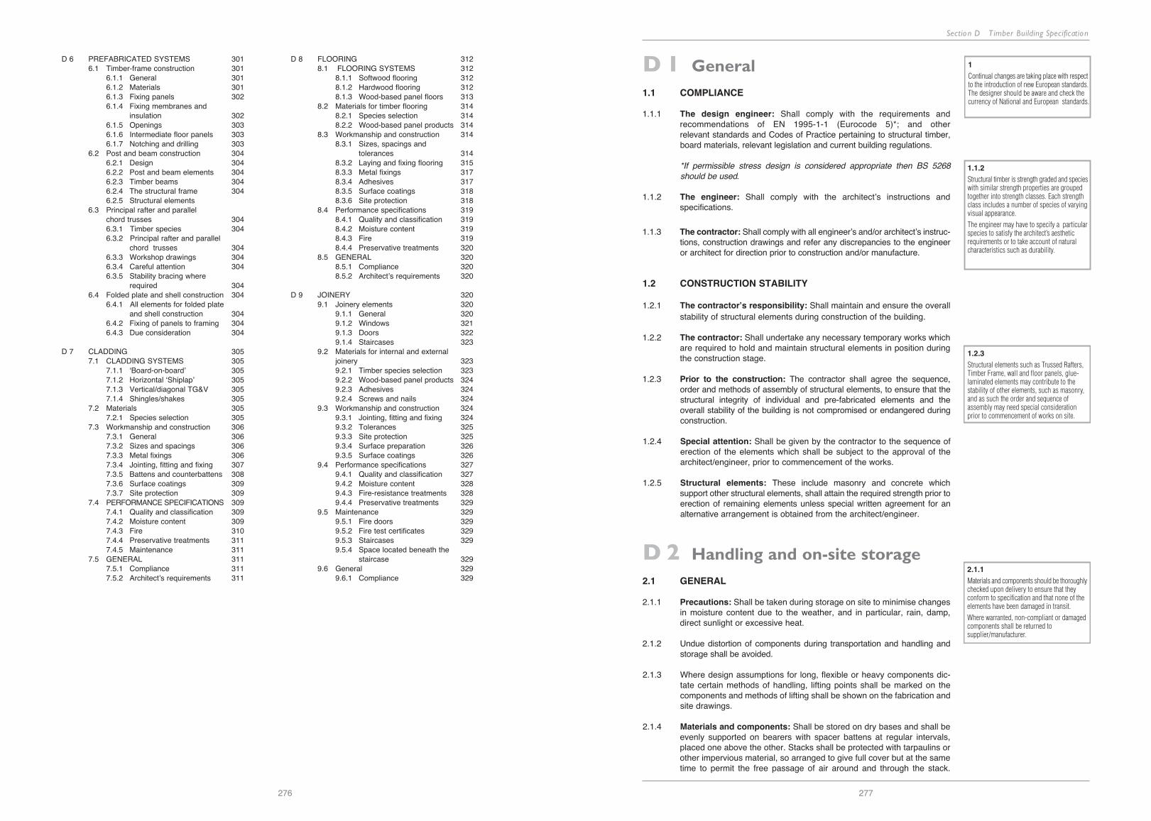
275 Note: The clauses used in this Timber Building Specification can be used to supplement the Sample Timber Specification of Section C where further detailed information is required. Alternatively they may be used as individual specification clauses as deemed appropriate by the specifier. Section D Timber Building Specifications D 1 GENERAL 277 1.1 Compliance 277 1.1.1 The design engineer 277 1.1.2 The engineer 277 1.1.3 The contractor 277 1.2 Construction stability 277 1.2.1 The contractor’s responsibility 277 1.2.2 The contractor 277 1.2.3 Prior to the construction 277 1.2.4 Special attention 277 1.2.5 Structural elements 277 D 2 HANDLING AND ON-SITE STORAGE 277 2.1 General 277 2.1.1 Precautions 277 2.1.2 Undue distortion 277 2.1.3 Design assumptions 277 2.1.4 Materials and components 277 2.1.5 Suitable conditions 278 2.1.6 Carcassing timber 278 2.1.7 Plywood and other wood-based materials 278 2.1.8 Installed materials 278 2.2 Panel products 278 2.2.1 Board protection 278 2.2.2 Board stacking 278 2.2.3 Protective wrapping 278 2.3 Trussed rafters 278 2.3.1 Handling 278 2.3.2 Horizontal storage 278 2.3.3 Ground clearance 278 2.3.4 Health and safety 278 2.4 Quality control and testing 278 2.4.1 Quality control 278 2.4.2 Testing 279 D 3 MATERIALS 279 3.1 Timber 279 3.1.1 Selection 279 3.1.2 Grading and strength classes 279 3.1.3 Dimensions 280 3.1.4 Moisture content 280 3.1.5 Preservative treatment 281 3.1.6 Fire Resistance and treatment 281 3.2 Panel products 282 3.2.1 Plywood 282 3.2.2 Oriented Strand Board (OSB) 283 3.2.3 Hardboard 284 3.3 Mechanical fastners 284 3.3.1 General 284 3.3.2 Bolted joints 286 3.3.3 Steel dowel joints 286 3.3.4 Toothed-plate connector joints 286 3.3.5 Split ring connector joints 287 3.3.6 Shear plate connectors 288 3.4 Adhesives 289 3.4.1 Structural wood adhesives 289 3.4.2 Test methods for adhesives 289 3.4.3 Adhesives for structural purposes 289 3.4.4 Adhesives 289 3.4.5 Surfaces for gluing 289 3.4.6 Moisture content 289 3.4.7 Treated timber 289 D 4 WORKMANSHIP AND CONSTRUCTION 290 4.1 General 290 4.1.1 Adequate supervision 290 4.1.2 Workmanship in fabrication and preparation 290 4.1.3 Materials applied used and fixed 290 4.1.4 Timber damaged, crushed or split 290 4.1.5 Moisture content of timber 290 4.1.6 Time of erection 290 4.2 On-site carpentry 290 4.2.1 General 290 4.2.2 Load-bearing stud walls 291 4.2.3 Ceiling joists 291 4.2.4 Purlins 291 4.2.5 Rafters 292 4.2.6 Flat roofs 292 D 5 PREFABRICATED ELEMENTS 292 5.1 General 292 5.1.1 Factory fabrication 292 5.1.2 Assembly 293 5.2 Glued laminated members 293 5.2.1 General 293 5.2.2 Fabrication 293 5.2.3 Erection 294 5.2.4 Finishes and marking 294 5.3 Plywood box and I-beams 295 5.4 Stressed skin panels 295 5.4.1 Design and materials 295 5.4.2 Fabrication 295 5.4.3 Erection 296 5.5 Trussed rafters 296 5.5.1 General 296 5.5.2 Design 297 5.5.3 Materials 297 5.5.4 Fabrication 297 5.5.5 Structural adequacy 298 5.5.6 Workmanship on site 298 5.5.7 Finishes and protection 299 5.5.8 Inspection 299 5.6 Laminated veneer lumber (LVL) 299 5.6.1 LVL validation 299 5.6.2 LVL design 299 5.6.3 Preservative treatment of LVL 299 5.6.4 Cutting, notching or drilling 299 5.6.5 Joints 299 5.6.6 Lateral support 299 5.6.7 End bearing 299 5.7 Parallam 300 5.7.1 Validation 300 5.7.2 Design 300 5.7.3 Dry exposure conditions 300 5.7.4 The use of PSB 300 5.7.5 Cutting, notching or drilling 300 5.7.6 Joints made with nails or bolts 300 5.7.7 Lateral support of beam compression edge 300 5.7.8 End bearing requirements 300 5.8 Composite I-joists 300 5.8.1 I-joist validation 300 5.8.2 Storage 300 5.8.3 Moisture content 300 5.8.4 Lateral restraint 300 5.8.5 Web stiffeners 300 5.8.6 Notching, cutting or drilling 300 5.8.7 Alignment 300
-
Upload
duongkhanh -
Category
Documents
-
view
243 -
download
2
Transcript of Woodspec - A Guide to Designing, Detailing and … Final - Section D.pdfWoodspec - A Guide to...
Woodspec - A Guide to Designing, Detailing and Specifying T imber in Ireland
274
11.3 STAIRCASES
11.3.1 Softwood staircasesStrings shall be Scots pine to class J30 of en 942 where not exposed. handrails,balustrades, newels, treads and risers shall be class J30 of en 942 where paint-ed or class J10 when exposed and decorated with a clear polyurethane finish.
Sizes and tolerances shall comply with bS 585: part 1 for domestic use only.workmanship shall be in accordance with bS 1186: part 2. Adhesive shall be one-part polyvinyl acetate complying with en 204. the moisture content at the time ofmanufacture and installation shall be 12±2% and all in accordance with the archi-tect's detailed drawings.
11.3.2 Hardwood staircasesthe hardwood staircases shall be constructed from prime quality American whiteoak with approved joints and adhesives all in accordance with architect's detaileddrawings, including slip resistant inserts to tread nosing and two-pack mattpolyurethane finish. moisture content at the time of manufacture and installationshall be 12±2%.
11.3.3 Building regulationslandings, balusters, handrails, and step rise and going shall comply with the cur-rent technical guidance document (note: Approved documents in the uK) to thebuilding regulations for their respective end use and as specified by the architect.
275
Note: The clauses used in this Timber Building Specification can be used to supplement the Sample TimberSpecification of Section C where further detailed information is required. Alternatively they may be used as individualspecification clauses as deemed appropriate by the specifier.
Section D Timber Building Specifications
d 1 generAl 2771.1 compliance 277
1.1.1 the design engineer 2771.1.2 the engineer 2771.1.3 the contractor 277
1.2 construction stability 2771.2.1 the contractor’s
responsibility 2771.2.2 the contractor 2771.2.3 prior to the construction 2771.2.4 Special attention 2771.2.5 Structural elements 277
d 2 hAndling And on-Site StorAge 2772.1 general 277
2.1.1 precautions 2772.1.2 undue distortion 2772.1.3 design assumptions 2772.1.4 materials and components 2772.1.5 Suitable conditions 2782.1.6 carcassing timber 2782.1.7 plywood and other
wood-based materials 2782.1.8 installed materials 278
2.2 panel products 2782.2.1 board protection 2782.2.2 board stacking 2782.2.3 protective wrapping 278
2.3 trussed rafters 2782.3.1 handling 2782.3.2 horizontal storage 2782.3.3 ground clearance 2782.3.4 health and safety 278
2.4 Quality control and testing 2782.4.1 Quality control 2782.4.2 testing 279
d 3 mAteriAlS 2793.1 timber 279
3.1.1 Selection 2793.1.2 grading and strength classes 2793.1.3 dimensions 2803.1.4 moisture content 2803.1.5 preservative treatment 2813.1.6 fire resistance and
treatment 2813.2 panel products 282
3.2.1 plywood 2823.2.2 oriented Strand board (oSb) 2833.2.3 hardboard 284
3.3 mechanical fastners 2843.3.1 general 2843.3.2 bolted joints 2863.3.3 Steel dowel joints 2863.3.4 toothed-plate connector
joints 2863.3.5 Split ring connector joints 2873.3.6 Shear plate connectors 288
3.4 Adhesives 2893.4.1 Structural wood adhesives 2893.4.2 test methods for adhesives 2893.4.3 Adhesives for structural
purposes 2893.4.4 Adhesives 2893.4.5 Surfaces for gluing 2893.4.6 moisture content 2893.4.7 treated timber 289
d 4 worKmAnShip And conStruction 2904.1 general 290
4.1.1 Adequate supervision 2904.1.2 workmanship in fabrication
and preparation 2904.1.3 materials applied used
and fixed 2904.1.4 timber damaged, crushed
or split 2904.1.5 moisture content of timber 2904.1.6 time of erection 290
4.2 on-site carpentry 2904.2.1 general 2904.2.2 load-bearing stud walls 2914.2.3 ceiling joists 2914.2.4 purlins 2914.2.5 rafters 2924.2.6 flat roofs 292
d 5 prefAbricAted elementS 2925.1 general 292
5.1.1 factory fabrication 2925.1.2 Assembly 293
5.2 glued laminated members 2935.2.1 general 2935.2.2 fabrication 2935.2.3 erection 2945.2.4 finishes and marking 294
5.3 plywood box and i-beams 2955.4 Stressed skin panels 295
5.4.1 design and materials 2955.4.2 fabrication 2955.4.3 erection 296
5.5 trussed rafters 2965.5.1 general 2965.5.2 design 2975.5.3 materials 2975.5.4 fabrication 2975.5.5 Structural adequacy 2985.5.6 workmanship on site 2985.5.7 finishes and protection 2995.5.8 inspection 299
5.6 laminated veneer lumber (lvl) 2995.6.1 lvl validation 2995.6.2 lvl design 2995.6.3 preservative treatment of lvl 2995.6.4 cutting, notching or drilling 2995.6.5 Joints 2995.6.6 lateral support 2995.6.7 end bearing 299
5.7 parallam 3005.7.1 validation 3005.7.2 design 3005.7.3 dry exposure conditions 3005.7.4 the use of pSb 3005.7.5 cutting, notching or drilling 3005.7.6 Joints made with nails
or bolts 3005.7.7 lateral support of beam
compression edge 3005.7.8 end bearing requirements 300
5.8 composite i-joists 3005.8.1 i-joist validation 3005.8.2 Storage 3005.8.3 moisture content 3005.8.4 lateral restraint 3005.8.5 web stiffeners 3005.8.6 notching, cutting or drilling 3005.8.7 Alignment 300
Section D T imber Building Specification
276 277
d 6 prefAbricAted SyStemS 3016.1 timber-frame construction 301
6.1.1 general 3016.1.2 materials 3016.1.3 fixing panels 3026.1.4 fixing membranes and
insulation 3026.1.5 openings 3036.1.6 intermediate floor panels 3036.1.7 notching and drilling 303
6.2 post and beam construction 3046.2.1 design 3046.2.2 post and beam elements 3046.2.3 timber beams 3046.2.4 the structural frame 3046.2.5 Structural elements
6.3 principal rafter and parallel chord trusses 3046.3.1 timber species 3046.3.2 principal rafter and parallel
chord trusses 3046.3.3 workshop drawings 3046.3.4 careful attention 3046.3.5 Stability bracing where
required 3046.4 folded plate and shell construction 304
6.4.1 All elements for folded plate and shell construction 304
6.4.2 fixing of panels to framing 3046.4.3 due consideration 304
d 7 clAdding 3057.1 clAdding SyStemS 305
7.1.1 ‘board-on-board’ 3057.1.2 horizontal ‘Shiplap’ 3057.1.3 vertical/diagonal tg&v 3057.1.4 Shingles/shakes 305
7.2 materials 3057.2.1 Species selection 305
7.3 workmanship and construction 3067.3.1 general 3067.3.2 Sizes and spacings 3067.3.3 metal fixings 3067.3.4 Jointing, fitting and fixing 3077.3.5 battens and counterbattens 3087.3.6 Surface coatings 3097.3.7 Site protection 309
7.4 performAnce SpecificAtionS 3097.4.1 Quality and classification 3097.4.2 moisture content 3097.4.3 fire 3107.4.4 preservative treatments 3117.4.5 maintenance 311
7.5 generAl 3117.5.1 compliance 3117.5.2 Architect’s requirements 311
d 8 flooring 3128.1 flooring SyStemS 312
8.1.1 Softwood flooring 3128.1.2 hardwood flooring 3128.1.3 wood-based panel floors 313
8.2 materials for timber flooring 3148.2.1 Species selection 3148.2.2 wood-based panel products 314
8.3 workmanship and construction 3148.3.1 Sizes, spacings and
tolerances 3148.3.2 laying and fixing flooring 3158.3.3 metal fixings 3178.3.4 Adhesives 3178.3.5 Surface coatings 3188.3.6 Site protection 318
8.4 performance specifications 3198.4.1 Quality and classification 3198.4.2 moisture content 3198.4.3 fire 3198.4.4 preservative treatments 320
8.5 generAl 3208.5.1 compliance 3208.5.2 Architect’s requirements 320
d 9 Joinery 3209.1 Joinery elements 320
9.1.1 general 3209.1.2 windows 3219.1.3 doors 3229.1.4 Staircases 323
9.2 materials for internal and external joinery 3239.2.1 timber species selection 3239.2.2 wood-based panel products 3249.2.3 Adhesives 3249.2.4 Screws and nails 324
9.3 workmanship and construction 3249.3.1 Jointing, fitting and fixing 3249.3.2 tolerances 3259.3.3 Site protection 3259.3.4 Surface preparation 3269.3.5 Surface coatings 326
9.4 performance specifications 3279.4.1 Quality and classification 3279.4.2 moisture content 3289.4.3 fire-resistance treatments 3289.4.4 preservative treatments 329
9.5 maintenance 3299.5.1 fire doors 3299.5.2 fire test certificates 3299.5.3 Staircases 3299.5.4 Space located beneath the
staircase 3299.6 general 329
9.6.1 compliance 329
D 1 General1.1 COMPLIANCE
1.1.1 The design engineer: Shall comply with the requirements and recommendations of en 1995-1-1 (eurocode 5)*; and other relevant standards and codes of practice pertaining to structural timber, board materials, relevant legislation and current building regulations.
*If permissible stress design is considered appropriate then BS 5268 should be used.
1.1.2 The engineer: Shall comply with the architect’s instructions and specifications.
1.1.3 The contractor: Shall comply with all engineer’s and/or architect’s instruc-tions, construction drawings and refer any discrepancies to the engineer or architect for direction prior to construction and/or manufacture.
1.2 CONSTRUCTION STABILITY
1.2.1 The contractor’s responsibility: Shall maintain and ensure the overall stability of structural elements during construction of the building.
1.2.2 The contractor: Shall undertake any necessary temporary works which are required to hold and maintain structural elements in position during the construction stage.
1.2.3 Prior to the construction: the contractor shall agree the sequence, order and methods of assembly of structural elements, to ensure that the structural integrity of individual and pre-fabricated elements and the overall stability of the building is not compromised or endangered during construction.
1.2.4 Special attention: Shall be given by the contractor to the sequence of erection of the elements which shall be subject to the approval of the architect/engineer, prior to commencement of the works.
1.2.5 Structural elements: these include masonry and concrete which support other structural elements, shall attain the required strength prior to erection of remaining elements unless special written agreement for an alternative arrangement is obtained from the architect/engineer.
D 2 Handling and on-site storage2.1 GENERAL
2.1.1 Precautions: Shall be taken during storage on site to minimise changesin moisture content due to the weather, and in particular, rain, damp, direct sunlight or excessive heat.
2.1.2 undue distortion of components during transportation and handling and storage shall be avoided.
2.1.3 where design assumptions for long, flexible or heavy components dic-tate certain methods of handling, lifting points shall be marked on the components and methods of lifting shall be shown on the fabrication and site drawings.
2.1.4 Materials and components: Shall be stored on dry bases and shall be evenly supported on bearers with spacer battens at regular intervals, placed one above the other. Stacks shall be protected with tarpaulins orother impervious material, so arranged to give full cover but at the sametime to permit the free passage of air around and through the stack.
1.2.3
Structural elements such as Trussed Rafters,Timber Frame, wall and floor panels, glue-laminated elements may contribute to thestability of other elements, such as masonry,and as such the order and sequence ofassembly may need special considerationprior to commencement of works on site.
1
Continual changes are taking place with respectto the introduction of new European standards.The designer should be aware and check thecurrency of National and European standards.
1.1.2
Structural timber is strength graded and specieswith similar strength properties are groupedtogether into strength classes. Each strengthclass includes a number of species of varyingvisual appearance.
The engineer may have to specify a particularspecies to satisfy the architect’s aestheticrequirements or to take account of naturalcharacteristics such as durability.
2.1.1
Materials and components should be thoroughlychecked upon delivery to ensure that theyconform to specification and that none of theelements have been damaged in transit.
Where warranted, non-compliant or damagedcomponents shall be returned tosupplier/manufacturer.

Section D T imber Building SpecificationWoodspec - A Guide to Designing, Detailing and Specifying T imber in Ireland
278
2.1.5 Suitable conditions: must be maintained where it is essential that materials and components are not exposed to high moisture. deliveries should be scheduled to coincide with assembly and erection activity.
2.1.6 where carcassing timber is to be stored on site it shall be delivered to site protected by a suitable material such as a breather membrane. where plastic packaging is used, the packaging shall be removed and the timber open stacked and suitably protected. Subject to the weather conditions, timber may be left unprotected but only for very short periods.
2.1.7 Plywood and other wood-based sheet materials: whether packaged or otherwise, shall be stored under cover.
2.1.8 installed materials and components shall be protected from the weather. Appropriate ventilation shall be provided to reduce the uptake of moisture.
2.2 PANEL PRODUCTS
2.2.1 boards shall be adequately protected from the effects of the weather during transportation. edges shall be protected from damage and all boards shall be stored flat to avoid distortion. details of the type and quantity of the boards shall accompany each delivery.
2.2.2 boards shall be stacked flat on bearers on a level surface. Spacing between bearers shall be such that there is no damage from sagging. bearers shall be aligned vertically over each other to help prevent distortion.
2.2.3 only when the boards are required for conditioning shall any protective wrapping be removed. boards shall be conditioned as far as possible to the equilibrium moisture content likely to be attained in service and/or as directed by the architect.
2.3 TRUSSED RAFTERS
2.3.1 Handling: trusses shall be handled and stored so as to prevent damage.particular attention should be paid to handling trusses in their flat, weaker plane.
2.3.2 Horizontal storage: trussed rafters shall be stored horizontally on levelled bearers at close centres, or vertically with supports provided only at node points.
2.3.3 Ground clearance: trussed rafters shall be stored clear of the ground and covered to prevent damage from the weather. Stacks shall be adequately ventilated.
2.3.4 trusses shall be lifted into place taking care to follow good health and safety practices. if needed the truss manufacturer/designer should be contacted to identify the appropriate lifting points.
2.4 QUALITY CONTROL AND TESTING
2.4.1 Quality control
2.4.1.1 on arrival on site, all materials shall be inspected by the contractor for damage and conformity to specification
2.4.1.2 timber shall be delivered to site clean and properly protected and bound.
2.4.1.3 if deviations outside the allowed tolerances occur in more than 10%, or as previously agreed, of any parcel of timber or wood based panels, that parcel shall be rejected.
2.4.1.4 Structural components shall be manufactured under an approved quality control system.
2.4.1.5 the contractor shall appoint a suitable person to supervise on-site quality control procedures, which shall be approved by the architect/engineer, prior to commencement of the works.
2.4.2 Testing
2.4.2.1 provision shall be made for the selection of samples of timber compo-nents and isolated elements for test, if and when requested by the archi-tect/engineer.
2.4.2.2 testing of timber and wood based materials and structural elements shall be in accordance with eurocode 5 (or bS 5268 if appropriate) and/or the appropriate component or product standards, or as agreed with the engineer/architect.
2.4.2.3 testing of timber and wood based materials and structural elements shall be carried out by an independent organisation agreed with the architect/engineer prior to undertaking such work.
D 3 Materials
3.1 TIMBER
3.1.1 Selection
3.1.1.1 Structural timbers used as an architectural material, and expressed as a finished element, shall be finished according to the architect’s directions.
3.1.1.2 the species shall be as specified by or as agreed with the architect and/or engineer.
3.1.2 Grading and strength classeshardwoods used in construction shall be machine strength graded to en 14081-4 or visually strength graded to bS 5756 and classified into strength classes as per en 1912, or the permissible stress values deter-mined from testing may be used.
3.1.2.1 Structural timber may be of the following strength classes:Structural Softwoods:
c14, c16, c18, c22, c24, c27*, c30*, c35*, c40**not readily available on the irish market.
bS 5268 part 2 has 2 additional strength classes tr 26 (primarily for trussed rafters) and tr20 (not readily available in Ireland). tr 26 is a machine grade and is included in en 14081-4.
Structural Hardwoods:d30, d35, d40, d50, d60, d70
3.1.2.2 All structural softwood timber shall be visually strength graded to iS 127 (or bS 4978) or mechanically strength graded to en 14081-4.
3.1.2.3 Structural softwood shall conform to a strength class as listed in en 338 (or bS 5268: part 2 if appropriate), or as specified and noted on drawings.
3.1.2.4 hardwoods used in construction shall be machine strength graded to en 14081-4 or visually strength graded to bS 5756 and classified into strength classes as per en 1912, or the permissible stress values determined from testing may be used.
3.1.2.5 the designer shall note the design strength class and/or species and grade on appropriate drawings and documentation.
2.2.2
Boards are manufactured to dimensionaltolerances to allow close fit to be achieved onjointing. Conditioning allows boards togradually attain the moisture content dictatedby the atmosphere within the building.
2.2.1Edge stacking is not recommended.
2.3.1Damage resulting from poor storage cancause the springing of nails.
3.1.1.1
When structural timber is exposed to view itshould show features such as grain, colourand texture. The sample chosen shall berepresentative of the species underconsideration and be of adequate size.
3.1.2.2
Structural softwood timber is strength gradedto IS 127 or EN 519. Strength classes are listedin BS 5268: Part 2, and IS 444. In olderbuildings you may encounter the previous BS5268 strength classes, (SC1, SC2,SC3,SC4,SC5) or the SR 11 strength classes (SCA,SCB, SCC).
The visual strength grades GS & SS do notchange.
3.1.2.4
Hardwoods used in construction shall bemachine strength graded to EN 519 orvisually strength graded by BS 5756 andclassified into strength classes as per EN 1912or the permissible stress values determned fromtesting may be used.
3.1.2.6
Hardwoods in the medium to high densityrange, when compared to softwoods, have
• greater strength and stiffness which can lead
to smaller cross sections being used for
load bearing elements
• availability in longer lengths and largersections
• higher density, giving superior fireresistance
• they are correspondingly more expensive
3.1.2.7
In certain circumstances (eg. where timber isto be finished with a clear finish and exposedto view),the end use may require markings tobe omitted for aesthetic reasons. In such casesa certificate of conformance shall accompanythe timber.The engineer may request additional infomationsuch as tolerance class which may prove useful.
3.1.1.2
Timbers available on the Irish market aredescribed and illustrated in Section E2. Irishand other suppliers can identify and sourceother Irish-grown or imported timbers of character.
279

Section D T imber Building Specification
281
Woodspec - A Guide to Designing, Detailing and Specifying T imber in Ireland
280
3.1.2.6 All structural timber shall be marked in accordance with the strength grading standards, which typically include:• the monitoring authority/certification body• the company registered no.• graders/machine identification no.• Strength class and/or visual grade• Species/Species group• grading standard • Source code
3.1.2.7 where markings have been omitted, each parcel of timber of a single grade shall be despatched under the cover of a certificate of compliance typically stating the following information;• Serial no. & date of cert.• grading company & customer’s name & address• purchase order no.• timber dimensions• date of grading• Strength grade & species• Strength class• Signature of the grader, countersigned by the supervisor
3.1.3 Dimensions
3.1.3.1 All dimensions quoted, and referred to on drawings, are target sizes.
3.1.3.2 Structural softwood timber shall be clearly specified by the designer by reference to strength class or by species and strength grade.
3.1.3.3 All softwood structural timber shall comply with the tolerances given in en 336 and listed in table d 3.1.3.3.2 below.
100 115 125 150 175 200 225
� � � � � �
� � � � � �
3.1.4 Moisture content
3.1.4.1 the moisture content of structural timber shall comply with the categories listed in table d 3.1.4.1.1.
3.1.4.2 timber shall be dried to an appropriate moisture content before strength grading and installation.
3.1.4.3 moisture content may be measured using an electrical moisture meter with insulated probes used in accordance with the manufacturer’sinstructions.
3.1.5 Preservative treatment
3.1.5.1 See Section c: Sample timber Specification
3.1.6 Fire Resistance and treatment
3.1.6.1 fire resistance of solid timber members shall be calculated in accordance with eurocode 5 (en 1995-1-2) or if appropriate bS 5268 part 4 : Section 4.1, or Section 4.2.
3.1.6.2 fire resistance of composite floor and wall elements shall be calculated in accordance with eurocode 5 or if appropriate bS 5268 part 4: Section 4.1, or. Section 4.2.
3.1.6.3 where the methods outlined in 3.1.6.1 and 3.1.6.2 are not appropriate the fire resistance may be determined by assessment or by testing to the relevant en or bS fire test standard.
3.1.6.4 the european classifications for fire spread of linings (reaction to fire) are described in en13501-1. bS 476 provides similar classifications for the surface spread of flame of materials which are categorised as one ofthe following: class 1, class 2, class 3 or class 4. technical guidance document b (fire) specifies another class - class 0 which is the highest class; the equivalent uK Approved document has the same classifica-tion system.
3.1.6.5 without treatment plywood, particleboard and hardboard are usually classified as class d-s3, d2 or for the bS system, class 3 surface spread of flame.
3.1.6.6 most timbers are inherently categorised as class d-s3, d2 or for the bS system class 3 surface spread of flame classification.
3.1.6.7 Adhesives used for the assembly of fire-resistant elements shall be a type I conforming to en 301.
3.1.6.8 All metal fasteners that contribute to the overall strength and stability of structural timber elements are required to be located below the anticipated char line, or have appropriate fire protection.
Service End use Average moisture Moisture content which shouldClass Condition content likely to be not be exceeded in individual
attained in service (%) pieces at time of erection (%)
3 External uses, 20 or more -fully exposed
2 Covered and generally 18 24unheated
2 Covered and generally 15 20heated
1 Internal uses in 12 20continuously heatedbuildings
Table D 3.1.4.1 Moisture content recommendations (BS 5268 Pt. 2)
3.1.1.1
When structural timber is exposed to view itshould show features such as grain, colourand texture. The sample chosen shall berepresentative of the species underconsideration and be of adequate size.
3.1.2.2
Structural softwood timber is strength gradedto IS 127 or EN 519. Strength classes are listedin BS 5268: Part 2, and IS 444. In olderbuildings you may encounter the previous BS5268 strength classes, (SC1, SC2,SC3,SC4,SC5) or the SR 11 strength classes (SCA,SCB, SCC).
The visual strength grades GS & SS do notchange.
3.1.2.4
Hardwoods used in construction shall bemachine strength graded to EN 519 orvisually strength graded by BS 5756 andclassified into strength classes as per EN 1912or the permissible stress values determned fromtesting may be used.
3.1.2.6
Hardwoods in the medium to high densityrange, when compared to softwoods, have
• greater strength and stiffness which can lead
to smaller cross sections being used for
load bearing elements
• availability in longer lengths and largersections
• higher density, giving superior fireresistance
• they are correspondingly more expensive
3.1.2.7
In certain circumstances (eg. where timber isto be finished with a clear finish and exposedto view),the end use may require markings tobe omitted for aesthetic reasons. In such casesa certificate of conformance shall accompanythe timber.The engineer may request additional infomationsuch as tolerance class which may prove useful.
3.1.1.2
Timbers available on the Irish market aredescribed and illustrated in Section E2. Irishand other suppliers can identify and sourceother Irish-grown or imported timbers of character.
3.1.3.2
Common softwood sawn lengths currentlyavailable are:3, 3.3, 3.6, 4.2, 4.8, 5.4, 6, 6.6, 7.2m.
Less common:3.9, 4.5, 5.1, 5.7m.
Commercial stock sizes available in Irelandmay differ from those available in the UKand Northern Ireland.
3.1.4
Moisture content needs to be specified andchecked on site. Degrade and distortion canoccur on drying out, if timber is not supplied,maintained and installed at the correctequilibrium moisture content likely to beattained in service. As wood-based panels aretypically manufactured at low moisture contentsthey are required to be conditioned to a highermoisture content to avoid expansion problems.
3.1.1.1
When structural timber is exposed to view itshould show features such as grain, colourand texture. The sample chosen shall berepresentative of the species underconsideration and be of adequate size.
3.1.2.2
Structural softwood timber is strength gradedto IS 127 or EN 519. Strength classes are listedin BS 5268: Part 2, and IS 444. In olderbuildings you may encounter the previous BS5268 strength classes, (SC1, SC2,SC3,SC4,SC5) or the SR 11 strength classes (SCA,SCB, SCC).
The visual strength grades GS & SS do notchange.
3.1.2.4
Hardwoods used in construction shall bemachine strength graded to EN 519 orvisually strength graded by BS 5756 andclassified into strength classes as per EN 1912or the permissible stress values determned fromtesting may be used.
3.1.2.6
Hardwoods in the medium to high densityrange, when compared to softwoods, have
• greater strength and stiffness which can lead
to smaller cross sections being used for
load bearing elements
• availability in longer lengths and largersections
• higher density, giving superior fireresistance
• they are correspondingly more expensive
3.1.2.7
In certain circumstances (eg. where timber isto be finished with a clear finish and exposedto view),the end use may require markings tobe omitted for aesthetic reasons. In such casesa certificate of conformance shall accompanythe timber.The engineer may request additional infomationsuch as tolerance class which may prove useful.
3.1.1.2
Timbers available on the Irish market aredescribed and illustrated in Section E2. Irishand other suppliers can identify and sourceother Irish-grown or imported timbers of character.
3.1.5For more detailed information see Section A4-Durability and Preservation. For detail ofpreservation specification see Section C -Sample Specification.
3.1.6
The fire resistance of an element is assessedin relation to its ability to resist:
• structural collapse.
• perforation by flame or hot gases allowingthe passage of heat.
• temperature rise on the non-exposed face.
3.1.5.3
EN 350-2 'Natural durability of solid wood -Part 2: Guide to natural durability and treatabilityof selected wood species of importance inEurope' outlines several classification schemesto describe the durability and treatability ofwood.
3.1.5.2/1
EN 335-1 outlines the hazard classes for woodand wood based products
EN 335-2 provides guidance for the applicationof hazard classes to solid wood
EN 335-3 provides guidance for the applicationof hazard classes to wood based panels
clS sizes 38 x 89 and 38 x 140 are readily available as well.

Section D T imber Building SpecificationWoodspec - A Guide to Designing, Detailing and Specifying T imber in Ireland
3.2 PANEL PRODUCTS
it is recommended that all panel products have a ce mark and that the ce mark be checked for its validity.
3.2.1 Plywood
3.2.1.1 plywood panel products for structural use shall conform to en 13986 and en 636. for designs to bS 5268 plywood may be selected from those listed in bS 5268 part 2 or shall have certification from a suitable body such as the Agrément board. marine plywood shall comply with bS 1088: marine plywood manufactured from selected untreated tropical hardwoods
3.2.1.2 plywood designed to bS 5268 part 2 shall be subject to the quality control procedures of one of the organisations listed in that standard, or to the controls listed by the certification body.
3.2.1.3 the specification for plywood shall state the following information where appropriate:• type• Standard• grade• Species• nominal thickness• number of plies• finish (sanded/unsanded)
3.2.1.4 plywood exposed to the weather shall have no open defects (e.g. checks, knots, holes, splits) on the exposed face(s) unless it is used only for a temporary application such as hoarding.
3.2.1.5 prior to receiving a painted finish, plywood shall be adequately sanded.
3.2.1.6 All cut edges that may be subject to weather exposure shall be sealed with a suitable sealant or applied finish. typically these shall be one of the following:• Special sealing compounds, such as pitch epoxy• non-setting mastic, where the plywood is set in frames.• timber beading bonded with suitable adhesives.
3.2.1.7 in construction the following procedures shall be observed: 1. lower edges of boards shall be bevelled to promote shedding of
water.2. plywood used as infill panels shall be fully painted before
installation and/or assembly.3. cavities behind boards shall be adequately ventilated and drained to
allow dispersal of moisture.4. clearance shall be allowed at selected joints to allow free drainage of
water.5. plywood junctions with masonry shall provide adequate clearance to
allow drainage, prevent capillary absorption of water and provide enough space for maintenance of edge sealing.
6. the bottom edges of boards shall stand well clear of flashings, roof coverings, sills, and the ground.
7. exposed and/or inadequately protected fixings shall be of non-ferrous metals and have adequate corrosion resistance.
3.2.2 Other Board Materials
3.2.2.1 table d 3.2.2.1 outlines the types and grades of boards commonly available in accordance with european standards.
Dry conditions - defined in terms of service class 1 of BS 5268 and EN 1995-1-1Humid conditions - defined in terms of service class 2 of BS 5268 and EN 1995-1-1
3.2.2.2 All load-bearing boards shall be clearly and indelibly marked with the information required by the product standard and shall typically include the following information:• manufacturer’s name, trade mark or identification mark• Standard to which board is manufactured • type/grade of board• nominal thickness• major axis (if not the length of the panel)• formaldehyde class• batch number or production week and year
3.2.1.4
Improved durability can be obtained by selectingspecific wood species of suitable durability asoutlined in EN 350-2. The application of hazardclasses of biological attack to wood basedpanels is given in EN 335-1,2,3.
3.2.1.1
When a plywood is referred to as an exteriorgrade of plywood, this refers to the durabilityof the adhesive and not to the durability of thespecies used in the plywood construction.Where a durable plywood is required, a plywoodwith a durable species or a treated less durablespecies shall be specified.
The appearance of face veneers is important foraesthetic reasons and it is prudent to checkwhether the description of the face veneer relatesto both outer veneers or only to one face, theother outer veneer being referred to as theback veneer.
3.2.1.3
Also consider specifying:
• Panel size
• Preservative treatment
• Moisture content
• Edge sealing treatment
• Bond quality
• Lay-up orientation
282 283
Section D T imber Building Specification
285
Woodspec - A Guide to Designing, Detailing and Specifying T imber in Ireland
284
3.2.3 Hardboard
3.2.3.1 hardboard is generally unsuitable for use in wet or damp conditions and shall not be exposed to damp conditions during the construction process, unless there is a specific requirement for conditioning. generally hardboard is only suitable for Service class 1 conditions.
3.3 MECHANICAL FASTENERS
3.3.1 General
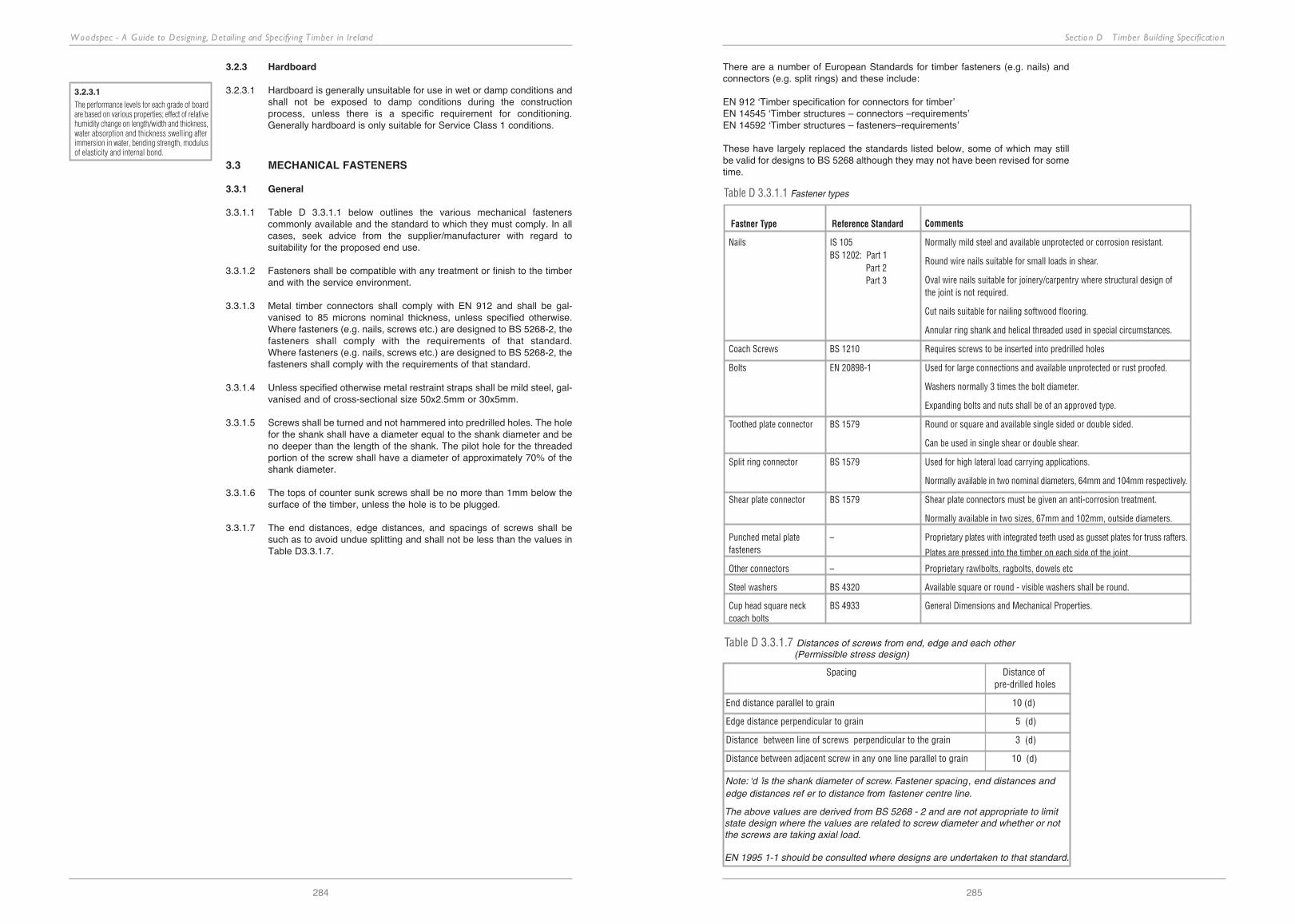
3.3.1.1 table d 3.3.1.1 below outlines the various mechanical fasteners commonly available and the standard to which they must comply. in all cases, seek advice from the supplier/manufacturer with regard to suitability for the proposed end use.
3.3.1.2 fasteners shall be compatible with any treatment or finish to the timber and with the service environment.
3.3.1.3 metal timber connectors shall comply with en 912 and shall be gal-vanised to 85 microns nominal thickness, unless specified otherwise. where fasteners (e.g. nails, screws etc.) are designed to bS 5268-2, the fasteners shall comply with the requirements of that standard. where fasteners (e.g. nails, screws etc.) are designed to bS 5268-2, the fasteners shall comply with the requirements of that standard.
3.3.1.4 unless specified otherwise metal restraint straps shall be mild steel, gal-vanised and of cross-sectional size 50x2.5mm or 30x5mm.
3.3.1.5 Screws shall be turned and not hammered into predrilled holes. the hole for the shank shall have a diameter equal to the shank diameter and be no deeper than the length of the shank. the pilot hole for the threaded portion of the screw shall have a diameter of approximately 70% of the shank diameter.
3.3.1.6 the tops of counter sunk screws shall be no more than 1mm below the surface of the timber, unless the hole is to be plugged.
3.3.1.7 the end distances, edge distances, and spacings of screws shall be such as to avoid undue splitting and shall not be less than the values in table d3.3.1.7.
Fastner Type Reference Standard Comments
Nails IS 105 Normally mild steel and available unprotected or corrosion resistant.BS 1202: Part 1
Round wire nails suitable for small loads in shear.Part 2
Oval wire nails suitable for joinery/carpentry where structural design ofPart 3the joint is not required.
Cut nails suitable for nailing softwood flooring.
Annular ring shank and helical threaded used in special circumstances.
Coach Screws BS 1210 Requires screws to be inserted into predrilled holes
Bolts EN 20898-1 Used for large connections and available unprotected or rust proofed.
Washers normally 3 times the bolt diameter.
Expanding bolts and nuts shall be of an approved type.
Toothed plate connector BS 1579 Round or square and available single sided or double sided.
Can be used in single shear or double shear.
Split ring connector BS 1579 Used for high lateral load carrying applications.
Normally available in two nominal diameters, 64mm and 104mm respectively.
Shear plate connector BS 1579 Shear plate connectors must be given an anti-corrosion treatment.
Normally available in two sizes, 67mm and 102mm, outside diameters.
Punched metal plate – Proprietary plates with integrated teeth used as gusset plates for truss rafters.fasteners Plates are pressed into the timber on each side of the joint.
Other connectors – Proprietary rawlbolts, ragbolts, dowels etc
Steel washers BS 4320 Available square or round - visible washers shall be round.
Cup head square neck BS 4933 General Dimensions and Mechanical Properties.coach bolts
Table D 3.3.1.1 Fastener types
Note: ‘d ’ is the shank diameter of screw. Fastener spacing, end distances andedge distances ref er to distance from fastener centre lin
The above values are derived from BS 5268 - 2 and are not appropriate to limit state design where the values are related to screw diameter and whether or not the screws are taking axial load.
EN 1995 1-1 should be consulted where designs are undertaken to that standard.
e.
Spacing Distance of pre-drilled holes
End distance parallel to grain 10 (d)
Edge distance perpendicular to grain 5 (d)
Distance between line of screws perpendicular to the grain 3 (d)
Distance between adjacent screw in any one line parallel to grain 10 (d)
Table D 3.3.1.7 Distances of screws from end, edge and each other(Permissible stress design)
3.2.3.1
The performance levels for each grade of boardare based on various properties; effect of relativehumidity change on length/width and thickness,water absorption and thickness swelling afterimmersion in water, bending strength, modulusof elasticity and internal bond.
3.2.3.1
The choice of hardboard for a particularapplication shall depend on strength anddurability requirements.
3.2.2.2
BS 7916 'Code of practice for the selection andapplication of particleboard, oriented strandboard (OSB), cement bonded particleboard andwood fibreboards for specific purposes'supercedes BS 5669 Part 3 'Particleboard -Specification for oriented strand board'.
there are a number of european Standards for timber fasteners (e.g. nails) andconnectors (e.g. split rings) and these include:
en 912 ‘timber specification for connectors for timber’en 14545 ‘timber structures – connectors –requirements’en 14592 ‘timber structures – fasteners–requirements’
these have largely replaced the standards listed below, some of which may stillbe valid for designs to bS 5268 although they may not have been revised for sometime.

Section D T imber Building Specification
287
Woodspec - A Guide to Designing, Detailing and Specifying T imber in Ireland
286
3.3.2 Bolted joints
3.3.2.1 washers with a nominal diameter and thickness of at least 3.0 times and 0.25 times the bolt diameter respectively, shall be fitted under the head of each bolt and under each nut unless the equivalent bearing is provided by a steel plate.
3.3.2.2 when tightened, a minimum of one complete thread shall be protruding from the nut.
3.3.2.3 bolt spacing - end distances, edge distances and spacings given in table d 3.3.2.3 below shall apply to bolted connections in timber.
Direction of loading End distance Edge distance Distance between
Loaded Un-loaded Loaded Un-loaded Across Parallelgrain to grain
Parallel to grain 7d 4d 1.5d 1.5d 4d 4d
Perpendicular to grain 4d 4d 4d 1.5d 4d 5d*
*Where the member thickness is less than 3 times the bolt diameter, the spacing parallelto the grain for bolts loaded perpendicular to grain may be taken as the greater of 3d or(2+t/d)d, where t is the member thickness and d is the bolt diameter.
Table D 3.3.2.3. Minimum bolt spacings
The above values are derived from BS 5268-2 and are not appropriate to limit state design.
EN 1995 1-1 should be consulted where designs are undertaken to that standard.
3.3.2.4 the diameter of holes in either timber or steel plate shall be as close to the nominal diameter of the bolts as practicable and in no case greater than 2mm larger than the diameter of the bolt.
3.3.2.5 timber shall not bear on the threads of bolts.
3.3.2.6 where metal plates are used in a joint, the metal shall not bear on the threads of the bolt.
3.3.3 Steel dowel joints
3.3.3.1 unless specified otherwise plain steel dowels should have a minimum tensile strength of 400n/mm2.
3.3.3.2 the minimum diameter of plain steel dowels used shall not be less than 6mm (or 8mm for designs to bS 5268-2).
3.3.3.3 the specified tolerances on plain steel dowels shall be -0mm /+0.1mm.
3.3.3.4 dowels shall be inserted into pre-bored holes in the timber members which shall have a diameter not greater than the dowel.
3.3.3.5 where plain steel dowels are used in timber/steel plate joints and the steel plate forms the outer member, the outer steel plate is to be secured in position by nuts and washers on threaded ends of plain steel dowels.
Spacings of steel dowels shall be as per bolt spacings (ref table d 3.3.2.3).
3.3.4 Toothed-plate connector joints
3.3.4.1 toothed-plate connectors shall conform to en 912 and be of the size and type specified.
3.3.4.2 round or square washers shall be fitted between timber and the head and nut of the bolt. the size of washer shall be appropriate to the bolt and connector size as shown in table d 3.3.4.2
Table D 3.3.4.2 Sizes of toothed-plate connectors and minimum sizes
Connector Minimum size of round orsquare washers
Diameter or Thickness length of side
mm mm mm
Round toothed plate,double and single-sided 38 M10 38 3
51 M12 38 3
64 M12 50 5
76 M12 60 5
Square toothed-plate,double and single-sided 38 M10 38 3
51 M12 50 3
64 M12 60 5
76 M12 75 5
Nominal sizeof connection
Nominal size andthread diameter
of bolt
Type
mm
3.3.4.3 bolt holes shall be within 2mm of their specified position.
3.3.4.4 bolt holes shall be as close as practicable to the nominal diameter of the bolt and in no case greater than 2.0 mm larger than the bolt diameter.
3.3.4.5 connectors shall not bear on the threads of bolts.
3.3.4.6 Joint preparation - the positions of bolt holes shall be accurately set out with reference to the point of the centre lines of the members, unless directed otherwise by the engineer.
3.3.4.7 connector spacing - the end distance, edge distance and spacing between connectors shall be as specified by the engineer.
3.3.4.8 in assembling a toothed-plate connector joint, the following procedure shall apply: 1. Assembly - toothed-plate connectors shall be embedded prior to the
insertion of the bolt by using a high-tensile steel bolt with plate washers larger than the connectors between the timber surfacesand the nuts of the two end nuts.
2. for large connectors or multi-member joints, thrust bearings shall be used under each nut.
3. the bolt shall be tightened sufficiently to embed fully theconnector teeth, and the washers used shall be of sufficient sizeto avoid undue crushing of the timber.
4. the joint shall be clamped before the bolt clamp is withdrawn and the permanent bolt with the appropriate size washers, is inserted.
3.3.4.9 toothed-plate connectors may only be used where full embedment of the teeth can be achieved.
the above values are derived from bS 5268-2 and are not appropriate to limit state design..
en 1995 1-1 should be consulted where designs are undertaken to that standard.
3.3.5 Split ring connector joints
3.3.5.1 Split ring connectors shall conform to en 912 and shall be the appropriate combination of connector, bolts and washers as shown in table d 3.3.5.1.

Section D T imber Building Specification
289
Woodspec - A Guide to Designing, Detailing and Specifying T imber in Ireland
288
Nominal size Nominal size and Min. size of round washers
of connector thread diameter of bolt Diameter/length of side Thickness mm mm mm mm
64 M12 50 3
102 M20 75 5
Table D 3.3.5.1 Sizes of split-ring connectors and minimum sizes
3.3.5.2 bolt holes shall be as close as practicable to the nominal diameter of the bolt, and in no case more than 2.0mm larger than the bolt diameter.
3.3.5.3 round washers shall be fitted between the timber and the head and nutof the bolt.
3.3.5.4 Joint preparation - the position of the bolt holes shall be set out accurate-ly with reference to the point of intersection of the centre lines of the members, unless specified otherwise by the engineer.
3.3.5.5 bolt holes shall be within 2mm of their specified position.
3.3.5.6 the contact surfaces of the timber members shall be grooved to the dimensions given in table d 3.3.5.6.
Split Ring Dimensions of Groove (in mm)
Diameter Inside Diameter Width Depth
64 65 4.6 9.5
102 104 5.3 12.7
Table D 3.3.5.6 Circular groove dimensions for split ring
3.3.5.7 connector spacing - ensure that the required minimum standard end dis-tance, edge distance and spacing between connectors are at least those values listed in table d 3.3.2.3.
the above values are derived from bS 5268-2 and are not appropriate to limit state design.
en 1995 1-1 should be consulted where designs are undertaken to that standard.
3.3.6 Shear plate connectors
3.3.6.1 Shear plate connectors shall be in accordance with en 912 and conform to the sizes given in table d 3.3.6.1
3.3.6.2 bolts and washers - the nominal diameter of the bolts to be used with shear plate connectors shall be those given in table d 3.3.6.1
3.3.6.3 bolt holes shall be as close as practicable to the nominal diameter of the bolt and in no case more than 2.0mm larger than the bolt diameter.
3.3.6.4 bolt holes should be within 2mm of their specified position.
3.3.6.5 connectors shall not bear on the threads of bolts.
3.3.6.6 Joint preparation - the positions of the bolt holes shall be set out accu-rately with reference to the point of intersection of the centre lines of the members.
3.3.6.7 connector spacing - the standard end distance, edge distance and spac-ing of connectors shall be those minimum dimensions listed in bS 5268 part 2 and appropriate to the connector sizes, unless specified otherwise by the engineer.
3.3.6.8 Assembly - sawdust, chippings and shavings shall be removed before inserting the shear plate into the recess.
the above values are derived from bS 5268-2 and are not appropriate to limit state design.
en 1995 1-1 should be consulted where designs are undertaken to that standard.
3.4 ADHESIVES
3.4.1 Structural wood adhesives: Shall comply with en 301: Adhesives phenolic and aminoplastic, for load-bearing timber structures: Classification and performance requirements.
type I adhesives, which will stand full outdoor exposure and temperatures above 50°c.
type II adhesives, which may be used in heated and ventilated buildings and exterior protected from weather.
3.4.2 Test methods for adhesives: Shall comply with en 302: “Adhesives for load-bearing timber structures - Test methods”, Parts 1-4.
3.4.3 Adhesives for structural purposes: Shall produce joints of such strength and durability that the integrity of the bond is maintained in the assignedservice class throughout the expected and/or design life of the structure.
3.4.4 Adhesives: the following adhesives may be considered subject to the design engineer’s approval:• resorcinol formaldehyde and phenol resorcinol formaldehyde• phenol-formaldehyde, hot setting• urea formaldehyde• melamine urea formaldehyde• casein adhesives
3.4.5 Surfaces for gluing: Shall be flat, smooth and free from grit, dust or other matter detrimental to the efficacy of the bond. bonding shall take place as soon as possible after planing/ sanding.
3.4.6 Moisture content: timber shall be conditioned, to a moisture content corresponding to the average moisture content likely to be attained in service, prior to gluing.
3.4.7 Treated timber: Shall not be glued without prior approval of the engineer.
3.4.1/1
Acceptable strength and durability can beachieved by using a polycondensation adhesiveof the phenolic or aminoplastic type as definedin EN 301. The adhesive shall meet therequirements for adhesive type 1 or 2 asappropriate to EN 301.
3.4.1/2
Not all adhesives can be classified in accordancewith EN 301. It is the responsibility of thedesigner/engineer to ensure the adhesivesselected are suitable for the specified serviceclass and comply with current regulations.
For glulam members refer to EN 386 GluedLaminated Timber - performance requirementsand minimum production requirements.

Section D T imber Building Specification
291
Woodspec - A Guide to Designing, Detailing and Specifying T imber in Ireland
290
D 4 Workmanship
4.1 GENERAL
4.1.1 Adequate supervision: there shall be adequate supervision through-out the preparation and construction of the structure to ensure that it conforms to the principles and practical considerations of the design.
4.1.2 Workmanship in fabrication and preparation: material shall conform in all respects to accepted good practice.
4.1.3 Materials applied used and fixed: materials shall be applied, used and fixed in such a way as to perform adequately the functions for which they are designed and intended.
reasonable access staging and platforms, shall be provided by the contractor to all the works and shall be complete and safe.
4.1.4 Timber damaged, crushed or split: timber which is damaged, crushed, or split beyond the limits permitted for similar defects in the grading, shall be rejected or repaired to the satisfaction of the design engineer.
4.1.5 Moisture content of timber: Shall be checked upon delivery by a properly calibrated moisture meter, used in accordance with the manufacturer’s instructions.
4.1.6 Time of erection: At the time of erection, the moisture content of timber shall not exceed the maximum permitted. (See table d3.1.4.1).
4.2 ON-SITE CARPENTRY
4.2.1 General
4.2.1.1 dimensions and spacing shall not be scaled from drawings.
4.2.1.2 discrepancies and/or deviations from drawings and details are to be reported to the architect/engineer for his/her direction.
4.2.1.3 the size, shape and finish of all members and materials shall conform to the detailed drawings and specifications.
4.2.1.4 connect timber roofs and suspended floors to walls in accordance with approved details, such as those recommended in technical guidance document part A to the irish building regulations: subject to any requirements shown on the engineer’s drawings.
4.2.1.5 metal straps shall be fixed in accordance with the manufacturer’s instructions and those of the design engineer.
4.2.1.6 where timber members spanning parallel to a wall are to be restrained, the straps shall be attached to bonders or solid noggings fixed firmly to the joists. Additionally there shall be a packing piece between the wall and the nearest joist.
4.2.1.7 the maximum amount of machining should be carried out prior to preservative or fire-retardant treatment.
4.2.1.8 where cross-cutting, boring, notching or other working is necessary after preservative treatment any exposed surfaces should be given two liberal brush coats of an appropriate preservative.
4.2.2 Load-bearing stud walls
4.2.2.1 load-bearing stud walls shall be designed to en 1995-1-1 or for permissible stress designs to bS 5268: part 2.
4.2.2.2 Studs shall be bridged at mid-height, and contained between head and sole plates of the same cross-sectional dimensions. two rows of noggins are required where the height exceeds 2.4m.
4.2.2.3 loads from load-bearing elements shall be transmitted directly to studs and hence to a suitable foundations. where loads are not transferred directly to a stud, a double head binder shall be used subject to the agreement of the design engineer.
4.2.3 Ceiling joists
4.2.3.1 ceiling joists should be chosen from the span tables given in Swift 6 (for ireland) or alternatively designed to en 1995-1-1 or for permissible stress designs to bS 5268: part 2.
4.2.3.2 ceiling joists are generally not suitable to sustain loads from purlins or water tanks. An alternative means of support shall be designed by the design engineer. (See detail b 1.4)
4.2.3.3 where ceiling joists are used to triangulate the rafters together, suitable fixings shall be made at the joist-rafter connection and at any ceiling joist splices, to ensure the continuity of all components forming the triangulation.
4.2.3.4 where ceiling joists run perpendicular to rafters (e.g. on a hip end roof) arrangements shall be made to tie hip end jack rafters with binders and diagonal ties in the plane of the ceiling.
4.2.3.5 where joists, trimmers, etc. do not have direct bearing support, approved galvanised steel hangers shall be used in accordance with the manufacturer’s recommendations.
4.2.3.6 notching and drilling of joists may be carried out within zones as shown in fig. A 2.1. in all other circumstances where it is necessary to pierce or notch a member, the engineer's prior approval shall be obtained. in exist-ing buildings, the design engineer shall be advised wherever existing notch-ing or drilling is found that does not comply with detail. fig A 2.1.
4.2.3.7 All trimmers and trimming joists and their connections shall be designed to en 1995-1-1 or for permissible stress designs to bS 5268: part 2.
4.2.4 Purlins
4.2.4.1 timber purlins shall be selected from tables given in Swift 6 (for ireland) or alternatively, they shall be designed in accordance with en 1995-1-1 or for permissible stress designs to bS 5268: part 2.
4.2.4.2 purlins that are aligned vertically shall have rafters birds-mouthed to fit over the top of purlin with a suitable connection and tie. purlins shall be adequately supported by a wall or other suitable structure. Structural arrangements shall be approved by the engineer.
4.2.4.3 purlins that are perpendicular to the rafter plane shall be supported with 75x100mm (minimum and subject to length) struts suitably restrained from horizontal movement. the loads shall be transmitted to load-bear-ing elements e.g., masonry, load-bearing partitions, timber or steel beams. Structural arrangements shall be approved by the design engineer.

Section D T imber Building Specification
293
Woodspec - A Guide to Designing, Detailing and Specifying T imber in Ireland
292
4.2.5 Rafters
4.2.5.1 Structural timber rafters may be chosen from the span tables given in Swift 6 (for ireland) or alternatively, shall be designed by the design engineer to en 1995-1-1 or for permissible stress designs to bS 5268: part 2.
4.2.5.2 where lining is affixed directly to the bottom edges of rafters, these shall be of a suitable depth to accommodate insulation and a ventilation void of 50mm above the insulation. A vapour check should be fitted on the warmside directly behind the linings.
4.2.5.3 A suitable arrangement shall be made to restrain horizontal movement of rafters at eaves level.
4.2.5.4 birdsmouthed notches in rafters over wall plates, purlins etc. shall be to a maximum depth of one-third of the rafter depth. design of the raftersshall take into account the reduced depth.
4.2.6 Flat roofs
4.2.6.1 flat roofs shall be laid at falls between 1 in 80 and 1 in 40 but in no case at less than 1 in 80.
4.2.6.2 timber firring pieces shall be tapered to suit the fall and laid on all timber joists.
decking shall be oSb 3 or plywood to en 636 (-2 humid or -3 exterior use) laid on firring pieces.
4.2.6.3 drainage shall be provided so that water will drain away without ponding.
4.2.6.5 for domestic roofs, provide a layer of chipping to felt roofs; alternatively provide ballast.
4.2.6.6 where a cold deck flat roof is specified provide a minimum 50mm ventilation space between joists and over the insulation. A vapour check should be tacked to the underside of the joists.
4.2.6.7 chipboard is not considered suitable for use as a decking in flat roofs.
4.2.6.8 proprietary roof vents are available.
D 5 Prefabricated elements5.1 GENERAL
5.1.1 Factory fabrication
5.1.1.1 proposed changes in design, materials and/or component arrangement shall be reported to the architect/engineer for approval, prior to manufacture.
5.1.1.2 detailed design calculations, and shop drawings, shall be submitted to the architect/engineer for approval, prior to manufacturing.
5.1.1.3 the architect/engineer shall be notified in writing by the manufacturer of the intended start and completion of the manufacture of components. they shall be invited to inspect and view the manufacturing process and the completed elements prior to dispatch to site.
5.1.1.4 when grade or other necessary identification marks are removed from timber components, provisions shall be made for remarking in accordance with en 1995-1.1 (or bS 5268-2 for permissible stress designs), iS 127 (or bS 4978), en 14081 or bS 5756.
5.1.1.5 where preservation treatments or flame-retardant treatments are required, care shall be taken to ensure that all machining, notching, cutting and drilling has taken place prior to the application of such treatments.
5.1.1.6 the assembled component shall conform to the geometry and layout drawings as specified by the designer and is to be achieved correctly within the specified tolerances.
5.1.1.7 during assembly and erection, no forces shall be applied to components which could cause damage or the permissible stresses to be exceeded. Special care may be necessary when handling framed arches and shaped beams.
5.1.1.8 dimensional tolerances of section sizes, the fit of assembled elements to each other and to secondary and primary elements shall comply with the specific requirements of the standard for the component requirements. where no standard exists, the approval of the architect and engineer shall be sought prior to manufacture, assembly and erection.
5.1.2 Assembly
5.1.2.1 the method of assembly and erection shall be such as to ensure that the geometry and layout of the assembled components, as specified by the designer, is within the specified tolerances.
5.1.2.2 the contractor shall submit to the design engineer, for approval, the proposed method and sequence of erection of prefabricated elements.
5.2 GLUED LAMINATED MEMBERS
5.2.1 General
5.2.1.1 All structural glued laminated timber elements shall be designed to conform to the requirements of eurocode 5 or if appropriate bS 5268: part 2.
5.2.1.2 glued laminated structural elements shall be manufactured to en 386.
5.2.1.3 in accordance with en 386, the following species are suitable for glued laminated elements: douglas fir, european redwood, european white-wood, hemlock, corsican pine, Austrian black pine, larch, maritime pine, poplar, radiata pine, western red cedar and Sitka spruce. other species may be approved for use subject to agreement with the architect.
5.2.1.4 All structural timber shall be strength graded to iS 127 or machine graded to the appropriate part of en 14081.
5.2.1.5 An approved fabricator shall be engaged by the main contractor to fabricate the glued laminated members.
5.2.1.6 Steel plates and brackets shall be cut and welded by an approved steelwork fabricator. they shall be galvanised to a minimum of 85 microns nominal thickness unless otherwise specified.
5.2.2 Fabrication
5.2.2.1 detailed shop drawings shall be prepared by the specialist fabricator where necessary; detailed calculations and specifications for all connections and bearings are to be prepared by the specialist fabricator to suit loadings specified by the engineer. Samples of steel connections and brackets shall be made up for the architect’s approval. Adequate notice must be given to allow for inspection of the first fabricated member in the works by the architect and engineer.
5.1.1
The engineer should thoroughly check allcalculations and shop drawings.
Scheduled and unscheduled factory visits shouldbe made to manufacturing plant byarchitect/engineer during the manufacturing oftimber structural components.

Section D T imber Building Specification
295
Woodspec - A Guide to Designing, Detailing and Specifying T imber in Ireland
294
5.2.2.2 beams shall conform to the final dimensions shown on the work drawings. the exact beam profile shall be subject to agreement by the architect. where applicable beams should be pre-cambered by the amount specified by the architect and agreed with the design engineer.
5.2.2.3 the required mc (moisture content) of the laminations at fabrication depends on whether or not the timber has been treated:
• non-treated timber at assembly: the mc in every lamination shall be in the range 8-15%, with the range of mc in a glulammember not exceeding 4%.
• treated timber at assembly: the mc in every laminationshall be in the range 11-18%, with the range of mc in a glulammember not exceeding 4%.
5.2.2.4 maximum lamination thickness shall not exceed the values given in en 386.
5.2.2.5 Sections shall be built up one lamination at a time.
5.2.2.6 finger joints in laminations shall be staggered in adjacent laminae.
5.2.2.7 Adhesives shall comply with type i or type ii as outlined in en 301. typically glue to be resorcinol-formaldehyde (rf) type in accordance with en 12765 and used strictly as recommended by the manufacturer. the adhesive shall be chosen considering the climatic conditions, species, preservative (if used) and production method.
5.2.2.8 All items shall be matched in the factory before fabrication in order to ensure correct fit.
5.2.2.9 exposed faces of beams shall be finished to the architect’s require-ments. A sample beam will be required for approval by the architect which, if accepted, may be incorporated in the works.
5.2.3 Erection
5.2.3.1 damaged or defective members shall be removed from site immediatelyand replaced with new ones to the architect’s approval.
5.2.3.2 the frame, purlins, etc., unless otherwise agreed, shall be erected, plumbed, lined, levelled and finally fixed by the specialist fabricator on their supports as indicated on the engineer’s drawing.
5.2.3.3 Sufficient temporary bracing shall be provided to ensure stability of frames, purlins etc.
5.2.3.4 All work including fabrication and site work shall be carried out by expe-rienced personnel under the supervision of a foreman approved by the architect or engineer.
5.2.4 Finishes and marking
5.2.4.1 finishes shall be in accordance with the architect’s requirements.
5.2.4.2 glued laminated structural elements shall be protected from damage and environmental degradation until handover of the building.
5.2.4.3 glued laminated members shall be marked with the following information:
(a) name or identity of producer (b) strength class and species of laminate(c) adhesive type(d) production week and year(e) certificate number(f) standard number
5.2.4.4 where it is not appropriate to mark the member for aesthetic reasons, a certificate containing the information in clause 5.2.4.3 shall accompany the glued laminated members along with additional information request-ed by the architect or engineer.
5.3 PLYWOOD BOX AND I-BEAMS
5.3.1 plywood box and `i' beams shall be designed in accordance with en 1995-1-1 or if appropriate bS 5268: part 2. these members should have an etA (european technical Approval) or an Agrément certificate; usually these documents will have load span tables and additional information relevant to their use.
5.3.2 for designs to bS 5268-2 manufacture shall be in accordance with bS 6446 "Specification for manufacture of glued structural components of timber and wood based panels".
5.3.3 Sawn timber shall comply with en 336 and shall be planed within 24 hours prior to assembly. flange members shall be strength graded to iS 127 or en 519.
5.3.4 plywood shall comply with the specification clauses 3.2.1.1 to 3.2.1.8 of this specification.
5.3.5 glue shall meet the requirements of en 301.
5.3.6 preservation, if specified, shall be in accordance with the appropriate hazard class.
5.3.7 At the time of assembly, the moisture content of the timber shall be between 14 and 18%.
5.4 STRESSED SKIN PANELS
5.4.1 Design and materials
5.4.1.1 Stressed skin panels shall be designed in accordance with bS 5268: part 2
5.4.1.2 materials for panel flanges shall be either plywood, oSb, particleboard or fibreboard. plywood shall meet the requirements of class 2 of en 314-2. oSb shall be grade oSb/4, or better, in accordance with en300; particleboard shall be grade p7 in accordance with en 312 and fibreboard shall be grade hb.hlA 1/2 in accordance with en 622.materials for the panel webs shall generally be softwood timber, strengthgraded either by visual or mechanical means to iS/127, en 518, en 519or bS 4978, to the strength classes specified in iS 444.
5.4.2 Fabrication
5.4.2.1 Stressed skin panels shall be manufactured to bS 6446 “Specification for manufacture of glued structural components of timber and wood based panels”.
5.4.2.2 insulation shall be provided between the web members where appropri-ate to meet the minimum thermal performance requirements outlined in the technical guidance documents of the building regulations or the client’s requirements. the insulation must be a tight fit and must be restrained during panel transit and site handling.
5.4.2.3 A ventilation space shall be provided in roof panel construction. it must be unobstructed over the full panel length and must be open at each end by providing holes in the blocking pieces subject to approval by the engineer. 500-gauge polythene vapour check shall be placed on the warm side of the insulation with the joints lapped and sealed, stapled to the surface of the flange panel before installation of the internal lining board.
5.2.2.2
The correct method of bracing is fundamentalto the adequate stability of the roof structure.
For non-standard roof arrangements, anengineer should advise and supervise thebracing and general design of the roof.
5.2.2.7
Acceptable strength and durability can beachieved by using a poly-condensationadhesive of the phenolic or aminoplastic typeas defined in EN 301. The adhesive shallmeet the requirements for adhesive type 1 or2 as appropriate to EN 301.
5.4
The maximum spans achievable are in theorder of 7 - 9 metres. Stressed skin panelscan be either single or double skinned.
5.3.1
Manufacturers specify different requirementsfor web stiffeners for I-beams but typicallystiffeners shall be provided on both sides ofthe web and fixed using 3.35mm diameternails at 50mm centres. Stiffeners shall be min.89mm wide and shall be fixed hard againstthe top surface of the bottom flange leaving aspecified gap between the top of the stiffenerand underside of the top flange.
Section D T imber Building Specification
297
Woodspec - A Guide to Designing, Detailing and Specifying T imber in Ireland
296
5.4.2.4 Surfaces to be glued must be free from oil, dust and foreign matter. the glue manufacturer’s specifications must be strictly adhered to. glue shall meet the requirements of en 301.
for non-structural applications glue shall meet the requirements of en 12765 if appropriate.
5.4.2.5 moisture content of timber at time of prefabrication shall not exceed 14% where panels will be used in a normal internal (heated) environment. for panels used in roof construction the moisture content of timber shall not exceed 18%.
5.4.2.6 no alterations to the panels shall be made without the prior approval of the engineer.
5.4.2.7 for panels without tension flanges, intermittent blocking at intervals not exceeding 3m shall be provided. All blocking timber shall be the same size as the web members.
5.4.3 Erection
5.4.3.1 where roof panels are erected against a ridge, temporary support shall be provided until the partner panel is in place.
5.5 TRUSSED RAFTERS
5.5.1 General
5.5.1.1 unless otherwise specified, trussed rafters shall comply with the recom-mendations of iS 193 or bS 5268: part 3.
5.5.1.2 All trussed rafters shall comply with the requirements of the national Standards Authority of ireland (nSAi) roof truss manufacturers’ Approval Scheme and each truss shall carry the nSAi Quality truss
tag.
5.5.1.3 responsibilities - the designer shall mean the building designer who shall, through the main contractor, make available all the necessary information, supplemented by site information provided by the main contractor, for the design of the trussed rafters and other elements to be carried out by the trussed fabricator (usually trained and using software supplied by the design system owner). the overall responsibility for roof design rests with the building designer. the trussed fabricator/design system owner shall be responsible for the design of the trussed rafters and shall provide a detailed design service and full manufacturing and assembly details for the fabricator in relation to each individual trussed rafter, compound girder, hip set assembly and valley set, their connec-tions to each other and seating requirements.
5.5.1.4 the main contractor shall obtain for the architect and engineer, from the truss fabricator/design system owner, written certification that he has received all the necessary information to enable him to provide the specified design service. the trussed fabricator/design system owner shall state explicitly in writing whether or not he has assumed, or his design requires, any bracing, tying etc., additional to that called up on the engineer’s or the architect’s drawings and specifications, and shall describe such additional bracing, tying etc., to the main contractor to enable the work to be carried out on site. copies of this information shall be sent to the architect/engineer to assist with any inspections carried out on site.
5.5.1.5 only trussed rafters designed and fabricated under the nSAi scheme will be acceptable for use in ireland.
5.5.2 Design
5.5.2.1 design loadings - trussed rafters and their connections shall be designed for the minimum loadings recommended in iS 193 or bS 5628: part 3.
5.5.2.2 detailed working drawings shall be submitted by the fabricator to the architect and engineer for approval, but this approval shall in no way relieve the main contractor, the fabricator or the design system owner of their responsibilities for the work. the drawings shall include a layout drawing and a drawing of each type of truss to be supplied. the latter shall show the strength class of the timber assumed in the design and the timber member sizes. At hipped roofs, details of supports for jack rafters, etc., shall be fully detailed on the drawings; at roof intersections details of compound trusses, special shoes etc., shall be detailed on the drawings. the drawings shall show for each truss type the type, dimensions and positioning of all metal plates or gussets together with the number of effective teeth, bursts or nails required in each member, at each joint.
5.5.2.3 All relevant dimensions and other particulars are to be checked and confirmed on site by the main contractor and the fabricator before fabrication of the trussed rafters commences.
5.5.3 Materials
5.5.3.1 timber species and strength grade shall be as specified by the engineer and/or shall be of a strength class appropriate to the design. where requested samples shall be delivered to the engineer for approval. great care shall be exercised to ensure that timber with excessive splits, knots or twist, is not used.
5.5.3.2 metal plates shall be of an approved type, hot dip galvanised and manufactured from steel with a minimum thickness of 0.91mm. plates shall comply with the recommendations of iS 193 or bS 5628: part 3.
5.5.4 Fabrication
5.5.4.1 detailed shop drawings shall be prepared by the fabricator where necessary.
5.5.4.2 detailed calculations and specifications for all connections and bearings are to be prepared by the fabricator to suit loadings specified by the engineer.
Steel plates and brackets shall be cut and welded by an approved steelwork fabricator. they shall be galvanised to a minimum of 85 microns nominal thickness unless otherwise specified.
5.5.4.3 Samples of steel connections and brackets shall be made up for the architect’s/engineer’s approval.
5.5.4.5 the fabricator shall take the greatest care in the choice of timber, and assembly techniques shall be of the highest order to match design requirements. the fabricator shall take particular care to ensure thattimber with splits, knots, twist etc., in excess of that permitted by iS 193 or (bS 5268) is not used; also that the correct strength class of timber and the correct member sizes as required by the design are used. Afterthe trussed rafters are erected and bracing and other members fixed, the roof structure shall be inspected by the engineer to ensure compliance with the design requirements.
5.5.1.1
The design of truss rafters has been developedby the design system owners who may be thetruss plate manufacturers. They have developedcomputer programmes to interpret loadingconditions to produce a design for individualtrusses, and roof systems.
These designs assume that adequate bracing,load distribution of water tanks and fixing takesplace on site.
5.5.1.3
Note: The trussed rafter fabricator operatesthe design software.
5.5.1.4
Trussed rafters fall into Hazard Class 1 or 2 forpreservative treatment.
Section D T imber Building Specification
299
Woodspec - A Guide to Designing, Detailing and Specifying T imber in Ireland
298
5.5.4.6 moisture content shall be a maximum of 20% at time of fabrication.
5.5.4.7 All members shall be planed all over and section sizes quoted on the drawings shall be understood to mean finished sizes after planing.
5.5.4.8 All items shall be matched in the factory before fabrication in order to ensure correct fit.
5.5.5 Structural adequacy
5.5.5.1 Assessment of structural adequacy may be by any of the methods specified in iS 193 or bS 5268: part 3. full details shall be submitted to the engineer at his request. where acceptance is based on tests on prototype units the test shall be carried out at the supplier’s expense by an independent testing authority and the results shall be forwarded directly to the architect by the independent authority. Acceptance of test results shall be at the sole discretion of the engineer.
5.5.6 Workmanship on site
5.5.6.1 each individual trussed rafter shall be inspected by the main contractor on arrival on site. bundles of rafters shall be opened and each truss inspected and re-stacked. these operations are essential and the contractor shall allow for their cost when pricing. the contractor’s attention is drawn to damage that can occur by mishandling on site; trussed rafters are very flexible and if allowed to bend or whip the plates may loosen.
5.5.6.2 defective truss rafters - damaged or defective trussed rafters shall be removed from the site immediately and replaced with new ones.
5.5.6.3 no modification to trussed rafters shall be carried out on site without the approval of the architect/engineer.
5.5.6.4 trussed rafters may not be birdsmouthed or otherwise cut except where shown on the approved drawings.
5.5.6.5 the trussed rafters shall be fixed to the wall plates with approved gal-vanised holding down clips and used in accordance with the manufac-turer’s recommendation (detail b2.4.1). the designer shall specify any special holding down fixings required to cater for any uplift forces.
5.5.6.6 the trussed rafters shall be fixed to the wall plates with approved galvanised holding down clips and used in accordance with the manufac-turer’s recommendation (detail b2.4.1). where uplift forces are likely to be experienced additional holding down devices in the form of vertical restraint straps, to conform to the requirements of part A of the building regulations, shall be specified on the supplier’s drawings and incorporat-ed in the work on site. (Section b2.3).
5.5.6.7 roof bracing and longitudinal binders shall be supplied and fitted by the main contractor as shown on the engineer’s drawings and as specified. these members shall be a minimum of 97x22mm section finished size and shall be skew-nailed with galvanised round wire nails, the type, number, diameter and length being in accordance with iS 193 (or bS 5268-3) and/or the designers’ requirements. bracing should be generally in accordance with the technical handbook of ‘the trussed rafter Association’ and with details issued by the truss fabricator/designer.
the following requirements for bracing and longitudinal binders shall generally be complied with (b 2.3).• provide continuously throughout every roof (or section of roof
between separating cross walls) 97x22mm raking main braces,twice nailed to the underside of rafters of every truss. the bracesshall run at approximately 45 degrees from ridge to eaves asshown in detail b2.3.1.
• provide, when the distance between centres of separatingcross walls is not more than 1.2 trussed rafter span, at least two97x22mm diagonal braces, twice nailed to every ceiling tie inevery roof (or section of roof between cross walls). where wall spacing exceeds 1.2 span, provide additional braces (totalling aminimum of four braces). Such diagonal braces to be in a ‘w’formation on each side, at an angle of 35 to 50 degrees.
• provide (unless trusses are less than 5m span), for everyroof or section of roof between cross walls, 97x22mm rakingbracing twice nailed to every internal strut (detail b2.3.3).
• provide longitudinal binders, 97x22mm, twice nailed and located at the node points as shown in detail b2.3.2. for thispurpose each binder shall be in two overlapping lengths. wherebinders cross main bracing the binders shall be interrupted andlap-jointed (detail b2.3.6).
• All joints in braces and binders shall be lapped and nailed over at least two rafters (detail b2.3.5).
• no bracing or binders shall penetrate a separating wall.• positioning of water tanks, pipes, flues etc., shall be arranged so as
not to interfere with or prevent proper fixing of bracing or binders.• where additional bracing or longitudinal binders, which are to be
fixed by the main contractor, are required by the truss and/or roofdesign, they shall be specified with details at the time of tendering.
5.5.6.8 temporary stability - the main contractor shall be responsible for the trussed rafters in all temporary conditions until the structure is complete.
5.5.7 Finishes and protection
5.5.7.1 protection and finishing on site by the main contractor shall comply with the architect’s requirements.
5.5.8 Inspection
5.5.8.1 the main contractor shall notify the engineer after the trussed rafters are erected and the bracing and other members are fixed to enable the engineer to inspect the roof structure, to ensure compliance with the design requirements.
5.6 LAMINATED VENEER LUMBER (LVL)
5.6.1 LVL validation: only lvl validated by an Agrément certificate or other authoritative assessment shall be used.
5.6.2 LVL design: lvl shall be designed in accordance with the Agrément certificate and/or bS 5268: part 2, using the grade stresses and moduli from the appropriate bS 5268 : part 2
5.6.3 Preservative treatment of LVL: Shall be considered in accordance with the appropriate plywood treatments and hazard class.
5.6.4 Cutting, notching or drilling: do not cut, notch or drill lvl without prior approval of the engineer. the manufacturer’s technical literature usually outlines allowable hole locations and dimensions.
5.6.5 Joints: Shall be designed in accordance with the Agrément certificate and/or bS 5268 part 2. maximum diameter of nails inserted parallel to the glue line should not exceed 4mm.
5.6.6 Lateral support: lateral support of the beam compression edge shall be provided at intervals of 600mm or closer unless specified differently in the design.
5.6.7 End bearing: requirements shall be in accordance with the manufacturer’s recommendations.
5.5.6.7
The correct method of bracing is fundamentalto the adequate stability of the roof structure.
For non standard roof arrangements , anengineer should advise and supervise thebracing and general design of the roof.(Section B 2.3).
5.5.6.1
The following is a list of faults whichrender trussed roof rafters defective - the list isnot exhaustive or complete:
• Plates not fully pressed home - a loss ofeven a few millimeters of penetration canseriously weaken a joint.
• Plates not the correct size or not located asshown on drawings.
• Plates with bent or flattened nails.
• Gaps between ends of abutting members ata joint in excess of 1.5mm.
• Plates not provided on both sides of a joint.
• Timber used with excessive splitting, knotsor twisting, etc.
• Correct grade of timber not used.
• Member sizes not in accordance with thedesign.
5.5.7.1
Care should be taken to minimise uptake ofmoisture due to exposure to weather.
5.6.1
Due to the stringent requirements inmanufacture and end-use applications LVLand Parallam need to be manufactured underthe control of the Agrément Board or similar authority.
5.5.7.1
Care should be taken to minimise uptake ofmoisture due to exposure to weather.
5.6.1
Due to the stringent requirements inmanufacture and end-use applications LVLand Parallam need to be manufactured underthe control of the Agrément Board or similarauthority .

Section D T imber Building SpecificationWoodspec - A Guide to Designing, Detailing and Specifying T imber in Ireland
300
5.7 PARALLAM
parallam is a trade name; the generic name for the material is parallel strand board (pSb). parallam has a bbA (at time of writing) and it is referenced below in the sense of the generic material.
5.7.1 Validation: only pSb validated by an Agrément certificate or other authoritative assessment shall be used.
5.7.2 Design: pSb shall be designed in accordance with the Agrément certificate and/or bS 5268: part 2.
5.7.3 Dry exposure conditions: pSb generally shall be used only in dry exposure conditions as defined in bS 5268: part 2.
5.7.4 The use of PSB: Shall be restricted to areas where preservative treatment is not required.
5.7.5 Cutting, notching or drilling: do not cut, notch or drill pSb without prior approval of the engineer. the manufacturer’s technical literature usually outlines allowable hole locations and dimensions..
5.7.6 Joints made with nails or bolts: Shall be designed in accordance with bS 5268: part 2.
5.7.7 Lateral support of beam compression edge: Shall be provided at intervals of 600mm centres or closer unless specified differently in the design.
5.7.8 End bearing requirements: Shall be in accordance with the manufacturer’s recommendations.
5.8 COMPOSITE I-JOISTS
5.8.1 I-joist validation: only i-joists validated by an Agrément certificate or other authoritative assessment shall be used.
5.8.2 Storage: Joists shall be stored clear of the ground and stacked on edge. full cover shall be provided but with provision for air circulation. operatives shall not be allowed to walk on the joists until braced.
5.8.3 Moisture content: Joists should arrive on site with a moisture content of 14 to18% and the moisture content shall be checked at the time of installation and shall be close to the moisture content likely to be attained in service. Some conditioning may be necessary to achieve this.
5.8.4 Lateral restraint: Shall be provided to the compression flanges by the provision of the fixing of boarding or battens at close intervals.
5.8.5 Web stiffeners: Shall be provided in accordance with the manufacturer’s recommendations.
5.8.6 Notching, cutting or drilling: do not notch, cut or drill the joists without prior consultation with the engineer.
5.8.7 Alignment: if rigid service pipes are to be incorporated within the floor or roof void, passing through the hole ‘knockouts’ in the joists, careful alignment may be needed during installation.
D 6 Prefabricated systems
6.1 TIMBER-FRAME CONSTRUCTION
6.1.1 General
6.1.1.1 the structural framework of timber-frame buildings shall conform to the design engineer’s requirements. the design shall be based on bS5268 parts 2, 4 and 6, loadings shall be based on tgd A and on bS 6399 parts 1 to 3. cp 3 ch v part 2 may be used instead of bS 6399 part 2 at the engineer’s discretion.
6.1.1.2 the design of a timber-frame structure shall be undertaken by an engineer, competent in timber design.
6.1.1.3 the manufacture of timber-frame elements shall take place in a controlled factory environment.
6.1.1.4 timber-frame structural elements shall be manufactured by a nSAi approved manufacturer
6.1.1.5 the erection process and subsequent building envelope enclosure shall be supervised and approved by an engineer competent in this form of construction.
6.1.2 Materials
6.1.2.1 the common stud sizes are 38x89mm for internal and party walls and 38x140mm for external walls.
Table D 6.1.2.1
6.1.2.2 preservative treatment(a) exposed softwood timber elements, or those in contact with
damp-proof courses or other elements likely to beexposed to direct weathering, shall be treated with apreservative to a schedule appropriate to timbers inuse/hazard class 3 or 3A as required.
(b) concealed timbers and those which are protected from directweathering, e.g. timber wall framing, flat roof, wall panels, ground floors, shall be treated with preservative to a schedule appropriate to timbers in use/hazard class 2.
6.1.2.3 external walls- the following sheet materials may be used for external wall panels, subject to the design engineer’s approval:
• oriented Strand board shall be grade oSb/3.• plywood shall be appropriate to structural design and shall be one
of the structural grades listed in bS 5268: part 2 or have appropriate certification (such as the Agrément board), plywood should conform to en 636 and be suitable for the end environmental conditions.
• exterior grade canadian or American (u.S.A.) unsanded plywoodsto the following standards are acceptable: cSA - 0121 - m 1978douglas fir plywood, cSA - 0151 - m 1978 canadian Softwoodplywood, nbS pS -1-83 - 1983 uS Softwood plywood. plywoodsmanufactured to these standards shall be quality assured by cofior ApA and marked by the appropriate grade stamp.
• Swedish softwood plywood shall be grade 30 or better.
5.8
In general, joists are classified as non-durable/perishable in accordance with BS 5268Part 5/BS 8417.
301

Section D T imber Building Specification
303
Woodspec - A Guide to Designing, Detailing and Specifying T imber in Ireland
302
6.1.2.4 other panel products that may be acceptable in timber-frame construc-tion are given in bS 5268 part 6.
6.1.2.5 thermal insulation - materials shall be used that, together with external wall construction, which will give a performance ‘u’ value to comply with the technical guidance document part l to the building regulations or to a value agreed with the architect. Acceptable insulations are:
• glass fibre - rock fibre• other semi-rigid insulation boards may be used upon approval.
6.1.2.6 breather membranes shall be in accordance with bS 4016, with a vapour resistance of less than 0.6 mns/g.
6.1.2.7 vapour checks - shall have a minimum vapour resistance of 250 mns/g and shall be either
• 500-gauge (125 micron) virgin polyethylene sheet,• aluminium foil kraft paper laminates*, or• vapour check plasterboard comprising metallised plastic laminate
bonded to the back face of a plasterboard sheet.*
* Subject to the product having the required minimum vapour resistance. In all situations an independent vapour check is required.
6.1.3 Fixing panels
6.1.3.1 Sheathing shall be fixed to studs by nailing at 150mm centres along board perimeters and at 300mm centres to intermediate studs using corrosion resistant nails, 50mm long, unless design dictates otherwise.
6.1.3.2 the nailing pattern for relevant sheeting material shall be determined by calculation as given in bS 5268: part 6.
6.1.4 Fixing membranes and insulation
6.1.4.1 breather membranes shall be fixed to sheeting with stainless steel staples.
6.1.4.2 breather membranes shall be generously lapped at joints and fixed to ensure water is shed away from the building. horizontal joint laps shall be at least 100mm and vertical laps shall be a minimum of 150mm. breather membranes shall lap over damp-proof courses and membranes to ensure drainage of water to outside of the building fabric at dpc, at sole plates, window and door head openings, at vertical jamb wall closures and at cills.
6.1.4.3 the stud locations shall be clearly marked in the outside face of the wall panel.
6.1.4.4 horizontal joints shall be taped or sealed or adequately fixed down. Small tears shall be repaired and holes sealed tightly around service connections.
6.1.4.5 vapour checks shall be carefully cut and dressed into door and window reveals. they shall overlap in insulated ground floors, and be folded and extended into ceilings by a minimum of 75mm.
6.1.4.6 where services are to be concentrated on or in external walls, avoid numerous punctures of vapour checks by providing a battened-out service zone of approximately 44mm between the face of vapour checks and backs of plasterboard..
6.1.4.7 mineral fibre (glass or rock) shall be a nominal minimum of 150mm in thickness, cut neatly to fill the void between studs. it shall be stapled to tops and sides of studs to ensure it remains in position. care shall be taken to ensure that the thickness of insulation is not decreased.
6.1.5 Openings
6.1.5.1 openings in load-bearing walls - where openings occur, they shall be spanned by suitably designed lintels with loads transmitted to foundations by cripple studs.
6.1.5.2 lintels - shall be designed and determined by the likely dead and imposed loads in service.
6.1.5.3 multi-member lintels shall be nailed and/or bolted together to an approved pattern.
6.1.5.4 independent steel lintels or steel beams are generally required to carry external masonry cladding.
6.1.6 Intermediate floor panels
6.1.6.1 floors shall be designed for imposed floor loadings specified in bS 6399.
6.1.6.2 floor structures may be any of the following components or combinations:• individual joists and flooring• fabricated joist panels (floor cassettes)• primary elements, e.g. glued laminated beams, i-joists, plywood
box beams or steel beams• Stressed skin panels
6.1.6.3 Alternative sizes for various spans, centres and strength classes may be chosen from iS 444. for other load conditions and complicated loading arrangements, joists shall be designed by a structural engineer to bS 5268: part 2.
6.1.7 Notching and drilling
6.1.7.1 Joists – simply supported joists may be notched for services to the following limitations. for details see fig A 2.1
(a) holes of size not greater than 0.25 of depth of joist and locatedon the centre line/neutral axis, should be in the zone between 0.25 and 0.4 of the span from supports. there shall be at least be 3 times the hole diameter or 100mm between holes whichever is the greater.
(b) notches of size not greater than 0.125 of the depth of the joistmay be made on the top of the joist in the zone between0.25 and 0.07 the length of the of span. notches should be no more than 75mm long and there should be at least 150mm between notches.
(c) the distance between notches and holes shall be at least the depth of the joist.
notches and holes outside the above limits or notches on the underside of the joist shall be designed.
6.1.7.2 Studs - unless otherwise justified by calculation, drilling of studs shall conform to the following requirements:
(a) holes of size not greater than 0.25 of depth of stud locatedon the centre line/neutral axis, in the zone between 0.1 and 0.25of the length of the stud; no more than 2 holes at either end ofeach stud.
notching is not permitted on studs unless specifically designed.

Section D T imber Building Specification
305
Woodspec - A Guide to Designing, Detailing and Specifying T imber in Ireland
304
6.2 POST AND BEAM CONSTRUCTION
6.2.1 Design: post and beam construction shall be designed to iS 444 or bS 5268: part 2.
6.2.2 Post and beam elements: Shall be manufactured off site by a competent timber frame or joinery manufacturer.
All ground-bearing posts shall be protected from rising damp by fitting steel shoes, suitably fixed and so arranged and designed as to shed water if exposed to weather.
6.2.3 Timber beams: where exposed to view, shall be neatly connected to posts.
6.2.4 The structural frame: Shall be made stable by one or a combination of all of the following stability features:
(a) independent inset wall panels in two vertical planes, andhorizontal floor panels.
(b) independent core capable of providing stability.
(c) diagonal bracing.
6.2.5 Structural elements: Supporting floors are required to have a fire resistance appropriate to the proposed end use.
6.3 PRINCIPAL RAFTER AND PARALLEL CHORD TRUSSES
6.3.1 Timber species: for principal rafter and parallel chord trusses shall be approved by the architect and engineer.
6.3.2 Principal rafter and parallel chord trusses: Shall be manufactured by an approved timber frame, trussed rafter or joinery manufacturer.
6.3.3 Workshop drawings: Shall be approved by the architect and engineer prior to manufacture.
6.3.4 Careful attention: is required to ensure correct fabrication of joints for both structural and architectural reasons.
6.3.5 Stability bracing where required: Shall be neatly made and connected to rafters to both architect’s and engineer’s approval.
6.4 FOLDED PLATE AND SHELL CONSTRUCTION
6.4.1 All elements for folded plate and shell construction: Shall be designed by the engineer and be factory manufactured in prefabricated elements by a suitable timber frame, trussed rafter or joinery manufacturer approved by the architect and engineer.
6.4.2 Fixing of panels to framing: Shall comply with the engineer’s details for nailing/adhesive patterns.
6.4.3 Due consideration: Shall be given to restraint of folded plate construction panel elements and the structure on which they are founded.
D 7 Cladding7.1 CLADDING SYSTEMS
Vertical ‘board-on-board’ cladding can be used provided its stepped arrangement in plan form is catered for at eaves, under junctions and at DPC level with regard for insect mesh, ventilation and end grain protection. See B8.4
7.1.1 ‘Board-on-board’
7.1.1.1 external wall cladding shall be ‘board-on-board’ vertical cladding european larch pressure impregnated with a suitable timber preservative, comprising inner boards at 200mm centres with 50mmbetween boards, and 100x38mm outer boards fixed with silicon bronze annular ring shank nails or austenitic stainless steel nails on 50x22mmpressure treated horizontal battens on 50x22mm vertical counter battens. preservative treated timber is to be re-dried after treatment to a moisture content of 16±3%.
7.1.2 Horizontal ‘Shiplap’When specifying horizontal ‘shiplap’ external timber cladding it is important that the end grain is always protected as its exposed location in horizontal cladding could lead to early deterioration of the timber.
7.1.2.1 external wall cladding shall be horizontal shiplap boarding, Douglas firpressure treated with timber preservative, comprising 175x25mm profile boards laid at 135mm centres fixed with austenitic stainless steel or silicon bronze nails on 50x22mm vertical battens which shall be pressure preservative treated. preservative treated timber to be re-dried following treatment to a moisture content of 16±3%. See b8.2 & b8.3
7.1.3 Vertical/diagonal TG&VTongued and grooved boards for external timber cladding should always be designed with a sufficient V joint so as to reduce mois-ture entrapment. See B8.2.
7.1.3.1 external wall cladding shall be tongued, grooved and v-jointed boards of western red cedar, laid horizontally, vertically or diagonally, comprising 100x20mm boards secret nailed with austenitic stainless steel or silicon bronze ringshank nails on 44x35mm (minimum) pressure impregnated vertical battens. when laid diagonally or horizontally the groove should be located above the tongue.
7.1.4 Shingles/shakesTimber shingles and shakes are only suitable for roofs with pitch-es greater than 45°. In pitches lower than this rain can drive up under the shingles and cause moisture entrapment and possibly early deterioration. See B.8.5. Preservative treatment is recommended in all cases.
7.1.4.1 timber roof cladding shall be shingles or shakes of western red cedar, double-lapped (laid similar to slating) with a minimum head lap of 150mm, fixed with copper nails onto horizontal battens 50x22mm on counter battens 50x22mm laid on a reinforced breather membrane/roofing felt. the battens shall be pressure treated with a suitable timber preservative. if a 30 year anticipated service life is required, then pressure treatment is recommended.
7.2 MATERIALS
7.2.1 Species selectionThe two most important factors concerning species selection are the aesthetic quality of the timber and its durability. Table A 10.1, which can be added to the specification, is provided to aid the designer in selecting a suitable species for external timber cladding.
7.2.1
See table A 10.1 for suitable species or referto Section E.
7.3
Avoid fixing cladding boards to each other.Instead they should be fixed independently tothe batten framework behind, allowing the freemovement of individual boards.
7.1.3.1Where vertical TG&V boards are specifiedhorizontal battens shall be laid on verticalcounter battens. (See Details B8.2.1, 8.2.2and 8.2.3).
7
7.1.1, 7.1.2, 7.1.3, 7.1.4.1 are samplespecifications only. Sizes may vary accordingto design and availability. Alternative species,sizes and fixings can be found in the sectionsbelow:
Species Selection 7.2.1
Sizes 7.3.2
Fixings 7.3.3
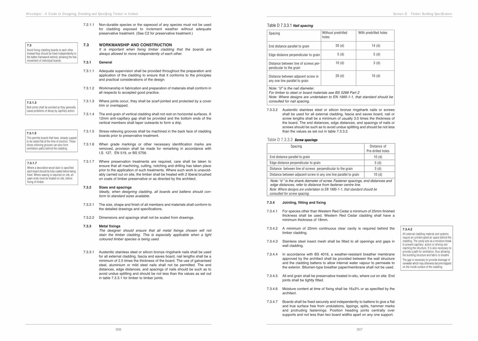
Section D T imber Building Specification
307
Woodspec - A Guide to Designing, Detailing and Specifying T imber in Ireland
306
7.2.1.1 non-durable species or the sapwood of any species must not be used for cladding exposed to inclement weather without adequate preservative treatment. (See c2 for preservative treatment.)
7.3 WORKMANSHIP AND CONSTRUCTION It is important when fixing timber cladding that the boards are always allowed to move independently of each other.
7.3.1 General
7.3.1.1 Adequate supervision shall be provided throughout the preparation and application of the cladding to ensure that it conforms to the principles and practical considerations of the design.
7.3.1.2 workmanship in fabrication and preparation of materials shall conform in all respects to accepted good practice.
7.3.1.3 where joints occur, they shall be scarf-jointed and protected by a cover trim or overlapped.
7.3.1.4 the end-grain of vertical cladding shall not rest on horizontal surfaces. A 12mm anti-capillary gap shall be provided and the bottom ends of the vertical members shall taper outwards to form a drip.
7.3.1.5 Stress-relieving grooves shall be machined in the back face of cladding boards prior to preservative treatment.
7.3.1.6 when grade markings or other necessary identification marks are removed, provision shall be made for remarking in accordance with i.S. 127, en 519, or bS 5756.
7.3.1.7 where preservation treatments are required, care shall be taken to ensure that all machining, cutting, notching and drilling has taken place prior to the application of such treatments. where such work is unavoid-ably carried out on site, the timber shall be treated with 2 liberal brushed on coats of timber preservative or as directed by the architect.
7.3.2 Sizes and spacingsIdeally, when designing cladding, all boards and battens should con-form to standard sizes available.
7.3.2.1 the size, shape and finish of all members and materials shall conform to the detailed drawings and specifications.
7.3.2.2 dimensions and spacings shall not be scaled from drawings.
7.3.3 Metal fixingsThe designer should ensure that all metal fixings chosen will not stain the timber cladding. This is especially applicable when a light coloured timber species is being used.
7.3.3.1 Austenitic stainless steel or silicon bronze ringshank nails shall be used for all external cladding, fascia and eaves board, nail lengths shall be a minimum of 2.5 times the thickness of the board. the use of galvanised steel, aluminium or mild steel nails shall not be permitted. the end distances, edge distances, and spacings of nails should be such as to avoid undue splitting and should be not less than the values as set out in table 7.3.3.1 for timber to timber joints.
Spacing
End distance parallel to grain
Edge distance perpendicular to grain
Distance between line of screws per-pendicular to the grain
Distance between adjacent screw inany one line parallel to grain
Without predrilled holes
20 (d)
05 (d)
10 (d)
20 (d)
With predrilled holes
14 (d)
05 (d)
03 (d)
10 (d)
Table D 7.3.3.1 Nail spacing
Note: “d” is the nail diameter.For timber to steel or board materials see BS 5268 Part 2Note: Where designs are undertaken to EN 1995-1-1, that standard should beconsulted for nail spacing.
7.3.3.2 Austenitic stainless steel or silicon bronze ringshank nails or screws shall be used for all external cladding, fascia and eaves board, nail or screw lengths shall be a minimum of usually 3.0 times the thickness of the board. the end distances, edge distances, and spacings of nails or screws should be such as to avoid undue splitting and should be not less than the values as set out in table 7.3.3.2.
Spacing Distance ofPre-drilled holes
End distance parallel to grain 10 (d)
Edge distance perpendicular to grain 5 (d)
Distance between line of screws perpendicular to the grain 3 (d)
Distance between adjacent screw in any one line parallel to grain 10 (d)
Note: “d ” is the shank diameter of screw. Fastener spacings, end distances andedge distances, refer to distance from fastener centre line.
Table D 7.3.3.2 Screw spacings
7.3.1.3
Butt-joints shall be avoided as they generallycause problems of decay by capillary action.
7.3.1.5
This permits boards that have already cuppedto be nailed flat at the time of erection. Thesestress relieving grooves can also formventilation paths behind the cladding.
7.3.1.7
Where a decorative wood stain is specifiedeach board should be fully coated before beingfixed. Where sawing is required on site, allsawn ends must be treated on site, beforefixing of timber.
Note: Where designs are undertaken to EN 1995-1-1, that standard should be consulted for screw spacing.
7.3.4 Jointing, fitting and fixing
7.3.4.1 for species other than western red cedar a minimum of 25mm finished thickness shall be used. western red cedar cladding shall have a minimum thickness of 18mm.
7.3.4.2 A minimum of 22mm continuous clear cavity is required behind the timber cladding.
7.3.4.3 Stainless steel insect mesh shall be fitted to all openings and gaps in wall cladding.
7.3.4.4 in accordance with bS 4016, a weather-resistant breather membrane approved by the architect shall be provided between the wall structure and the cladding battens to allow internal water vapour to permeate to the exterior. bitumen-type breather paper/membrane shall not be used.
7.3.4.5 All end grain shall be preservative treated in-situ, where cut on site. end joints shall be tightly fitted.
7.3.4.6 moisture content at time of fixing shall be 16±3% or as specified by the architect.
7.3.4.7 boards shall be fixed securely and independently to battens to give a flat and true surface free from undulations, lippings, splits, hammer marks and protruding fastenings. position heading joints centrally over supports and not less than two board widths apart on any one support.
7.2.1
See table A 10.1 for suitable species or referto Section E.
7.3
Avoid fixing cladding boards to each other.Instead they should be fixed independently tothe batten framework behind, allowing the freemovement of individual boards.
7.1.3.1Where vertical TG&V boards are specifiedhorizontal battens shall be laid on verticalcounter battens. (See Details B8.2.1, 8.2.2and 8.2.3).
7.3.1.3
Butt-joints shall be avoided as they generallycause problems of decay by capillary action.
7.3.1.5
This permits boards that have already cuppedto be nailed flat at the time of erection. Thesestress relieving grooves can also formventilation paths behind the cladding.
7.3.1.7
Where a decorative wood stain is specifiedeach board should be fully coated before beingfixed. Where sawing is required on site, allsawn ends must be treated on site, beforefixing of timber.
7.3.4.2
All external cladding material and systemsrequire an uninterrupted air space behind thecladding. The cavity acts as a moisture breakto prevent capillary action or driving rainreaching the structure. It is also necessary toprovide a path for ventilation, thus allowingthe building structure and fabric to breathe
The gap is necessary to provide drainage ofrainwater which may otherwise become trappedon the inside surface of the cladding.
7.3.4.8
This allows for movement of boards andfastenings to prevent cupping, spring andexcessive opening of joints or other defects.
Boards to be laid according to architects’drawings in order to avoid problems ofcupping. (See detail B8.4.3) This permitsboards that have already cupped to be nailedflat at the time of erection. Stress relievinggrooves can also form ventilation paths behindthe cladding. (See detail B8.2.3)
Section D T imber Building Specification
309
Woodspec - A Guide to Designing, Detailing and Specifying T imber in Ireland
308
7.3.4.8 boards less than 50mm wide that are not restrained by other boards, may be fixed with one nail at each support point. unrestrained boards over 50mm should be twice nailed at each support, and nails not spaced more than 50mm apart.
7.3.4.9 restrained boards, such as t&g or shiplap, shall be up to a maximum width of 100mm. they shall be singly fixed and nails shall be concealed.
7.3.4.10 the head of the nail shall finish flush with the surface of the boards, without any indentation of the surface or hammer marks.
7.3.4.11 where a translucent wood stain is to be used, no fillers for timber shall be permitted.
7.3.4.12 if an opaque finish (external paint) is to be used, the nails shall be punched below the board surface and stopped with a suitable moisture-resisting filler before finishing.
7.3.4.13 external timber shall be separated and raised from the ground by at least 150mm clear, to protect from ground splashing and capillary action.
7.3.4.14 timber shingles/shakes shall be laid on battens to separate them from the breather membrane or sarking felt. where sheathing (sarking board) is laid on top of rafters, counter-battens following the roof slope shall be fixed before tiling battens are fixed in position.
7.3.4.15 Shingles/shakes shall be double lapped, twice fixed with copper nails and spaced to allow a minimum 20mm gap.
7.3.4.16 for roof pitches of 45° or greater and where exposure conditions are moderate, the head-lap shall be a minimum of 100mm and the side-lap shall be half the single width.
7.3.4.17 Shingles/shakes shall be free to move independently of each other to avoid moisture movement stress and cracking, therefore they shall not be nailed where over-lapping occurs.
7.3.4.18 discrepancies and/or deviations in drawings and details are to be reported to the architect/engineer for their direction.
7.3.5 Battens and counterbattensBattens are primarily used to fix the cladding system away from the structure of the building, allowing ventilation and drainage. For this reason it is important that there is always a clear vertical space behind the cladding boards. When using vertical boards the fixing battens will have to run horizontally, so vertical counter battens will also have to be used.
7.3.5.1 battens and counterbattens shall be to sizes as described in architect’s drawings/details and to be pressure treated with a suitable preservative.
7.3.5.2 exposed ends of joints shall be treated in-situ by painting ends prior to fixing.
7.3.5.3 battens to be fixed with non-corrosive metals such as austenitic stainless steel or silicon bronze ringshank nails the length of which to be twice the thickness of the batten.
7.3.5.4 battens/counterbattens to be fixed horizontally and vertically, correctly and evenly spaced throughout. the size, number and location of the fixings shall be as specified by the architect/engineer.
7.3.5.5 moisture content of battens shall be 18±2% at time of fixing.
7.3.5.6 battens to be regularised softwood free from decay, insect attack and with no knot wider than half the width of the section.
7.3.6 Surface coatingsUnprotected timber cladding is exposed to changes in moisture content which can lead to surface cracking, while ultra-violet degra-dation by sunlight can lead to the loss of the timber’s natural colour. The high relative humidity in Ireland throughout the differ-ent seasons of the year is conducive to mould grown on timber. Only the heartwood of naturally durable timbers such as Irish oak, American white oak, iroko, teak or western red cedar should be considered for external cladding unprotected by preservative or a timber stain. Free-draining dry areas of cladding will eventually go grey but any ledges, damp areas or tight abutments will go a darker colour due to mould growth. Western red cedar ages well provided it does not suffer abrasion, is detailed properly, has a minimum finished thickness of 18mm and is not exposed to extreme weathering. Its low density of 390kg/m3 compared to American white oak’s 770kg/m3 means that abrasion, indentation and its poor ability to hold fixings can be a problem. Pressure impregnated preservative will greatly improve the performance of all species suitable for external cladding (and is necessary for all sapwoods). Timber stains will help maintain the surface protection of cladding from ultra-violet degrade and mould growth but need maintenance usually every 3 to 5 years. Clear or very light wood stains are not as protective as the darker reds or browns.
Varnish is unsuitable for external use in the Irish climate.
7.3.6.1 cladding shall be given 1 protective coat of selected pigmented microporous finish all round prior to site fixing, followed by 2 coats all in accordance with the manufacturer's instructions to the satisfaction of the architect. Any ends cut on site shall be re-finished.
7.3.7 Site protectionStorage time on site should be minimised and every effort should be made to schedule delivery and erection times together.
7.3.7.1 transportation of cladding to site storage and handling shall be in accordance with bS 5268.
7.3.7.2 Any damage, incorrect fixing or increase in moisture content may lead to the condemning and rejection of installed cladding.
7.4 PERFORMANCE SPECIFICATIONS
7.4.1 Quality and classification
7.4.1.1 timber used fo external cladding shall comply with bS 1186.
7.4.2 Moisture contentCladding moisture content can vary depending on seasonal changes and the orientation of the building. Pressure-preserved and stained timber varies less than untreated timber. Species selection, detailed design of cladding board profiles and junctions will also assist in controlling moisture movement.
7.4.2.1 moisture content of external cladding shall be 13 to 19% in accordance with en 942.
7.4.2.2 cladding treated with preservative shall be re-dried to 13 to 19% moisture content.
7.3.4.2
All external cladding material and systemsrequire an uninterrupted air space behind thecladding. The cavity acts as a moisture breakto prevent capillary action or driving rainreaching the structure. It is also necessary toprovide a path for ventilation, thus allowingthe building structure and fabric to breathe
The gap is necessary to provide drainage ofrainwater which may otherwise become trappedon the inside surface of the cladding.
7.3.4.8
This allows for movement of boards andfastenings to prevent cupping, spring andexcessive opening of joints or other defects.
Boards to be laid according to architects’drawings in order to avoid problems ofcupping. (See detail B8.4.3) This permitsboards that have already cupped to be nailedflat at the time of erection. Stress relievinggrooves can also form ventilation paths behindthe cladding. (See detail B8.2.3)
7.3.7
Where it is essential that materials andcomponents have low moisture contents, it maybe necessary to maintain suitable conditionson site, and/or to schedule deliveries to coincidewith assembly and erection activities.
7.4.1
There is no Irish or British standard codeof practice for exterior cladding. Therefore thereare no standard grades or profiles.BS 1186: Quality of timber in joinery may beused as a basis to specify timber cladding.Class 2 and 3 of this code are generally suitablefor external cladding and trim and are obtainablein commercially available softwood andhardwood. Class 3 is normally accepted as aserviceable quality for most claddingapplications.

Section D T imber Building Specification
311
Woodspec - A Guide to Designing, Detailing and Specifying T imber in Ireland
310
7.4.2.3 the moisture content of timber is to shall be checked upon delivery by a properly calibrated moisture meter, used in accordance with the manufacturer’s instructions. the moisture content readings shall be recorded for inspection by the architect if requested.
7.4.3 Fire
the construction of external walls and the separation between buildings to prevent external fire spread are closely related, technical guidance document b fire Safety lays down requirements for external walls in relation to their surface spread of flame classification and their fire resistance. in determining fire safety requirements it always advisable to consult tgd b and where necessary the local fire officer. the advice below is taken from tgd b (1997).
in relation to surface spread of flame, the external walls of buildings less than 1m from the relevant boundary should have a surface spread of flame classification of 0 up to a height of 30m, after 30m the external wall surface should be non-combustible. tgd b gives permitted limits on the amount of unprotected areas which may be disregarded for space separation purposes. effectively timber cladding is not permitted where the building is less than 1m from the relevant boundary.
the performance of external walls 1m or more from the relevant boundary depends on the purpose group of the building. for buildings such as flats or maisonettes, residential (institutional), other residential, assembly or for recreational purposes; then the external wall surface if 10m or less above ground level (or above a roof or any part of a building where people have access) is required to have an index of performance (i) not more than 20 but timber cladding at least 9mm thick is acceptable. this index of performance requirement is applicable to all building types up to a height of 20m. between 20m and 30m for all building types the external surface should be class 0 and above 30m the external surface should be non-combustible.
unprotected areas include those parts of an external wall which are:• A window, door or other opening • Any part of the external wall which has less than the required fire
resistance• Any part of the external wall which has combustible material more
than 1mm thick attached or applied to the external face whether from cladding or any other purpose
Table D 7.4.3.1 indicates the separation distances on external timber cladding and is based on the table in Method 1 in TGD B setting out the permitted unprotected areas in small residential buildings. The further the timber-clad building is from the relevant boundary the less restric-tions there are on the extensive use of timber. TGD B should be consult-ed on the precise rules governing space separation and for other cal-culation methods for different building types.
Min. distance Max. length Max. total
from boundary (m) of wall (m) unprotected area (m2)
1.0 24 5.6
2.5 24 15
6.0 24 No limit
Table D 7.4.3.1 Fire restrictions on external timber cladding
7.4.4 Preservative treatmentsNew European standards for preservation treatment have been introduced. For additional information see Section A Design Guidance (A4) and Section C, Sample Timber Specification (C2) for treatment specifications.
7.4.5 Maintenance
7.4.5.1 All external timber shall be regularly inspected for signs of decay. where decay is identified the causes should be remedied as soon as possible.
7.4.5.2 fungal, mould or moss growth on damp timber work shall be removed and the timber preservative treated by brush application.
7.4.5.3 particular attention should be paid to treating and sealing exposed end-grain.
7.4.5.4 fissures, shakes, cracks and loose knots should be liberally treated with preservative, where appropriate.
7.4.5.5 metal fasteners should be checked for corrosion and stress weakening. these shall be immediately replaced if necessary.
7.4.5.6 the erosion and fading of surface coatings such as emulsion paints and wood stains is caused by weathering and should be expected. the sur-face may require reapplication of surface coatings every three years, or less in exposed locations. properly applied microporous finishes have a longer life, typically 3-5 years.
7.5 GENERAL
7.5.1 Compliance
7.5.1.1 comply with the requirements and recommendations of bS 1186 and other relevant standards and codes of practice pertaining to external timber cladding, board materials, relevant legislation and current building regulations.
7.5.1.2 the building regulations require materials fit for their intended purpose. materials adversely affected by moisture shall be protected by damp-proof courses, detail design and preservative treatment.
7.5.1.3 All dimensions shall be finished dimensions as detailed in drawings.
7.5.2 Architect’s requirements
7.5.2.1 comply to the specifier’s requirements with regard to product selection, fixing and surface coatings.
7.5.2.2 proposed changes in design, materials and/or component arrangement shall be reported to the architect/engineer for approval, prior to manufacture.
7.5.2.3 Samples and dimensions of cladding shall be submitted to the architect /engineer for approval prior to installation.
7.5.1
There is no Irish or British standard codeof practice for exterior cladding, however, BS1186:“Quality of timber in joinery” is sometimesused as a basis for specifying exterior timbercladding or EN 942
7.4.5.6
The preparation for re-staining consists of arub-down with a stiff brush to remove dust anda washdown with white spirit or anammonia/water solution. Avoid wire-brushingwhich leaves wire fragments which will rust.
7.5.2
When choosing cladding as an exterior finish,it is desirable that the building design providesprotection by overhanging eaves and that itis protected throughout construction to itscompletion.
7.4.4
Documented evidence should be provided withthe delivery of treated timber, specifying thepreservation type, % salts retention andtreatment cycle.
7.4.3.2
Technical Guidance Document Part B outlines
the requirements for the provision of fire stops
and cavity barriers (refer to B 6.12).

Section D T imber Building SpecificationWoodspec - A Guide to Designing, Detailing and Specifying T imber in Ireland
D 8 Flooring8.1 FLOORING SYSTEMS
The most important factor affecting the behaviour of timber flooring is moisture movement so adequate room for expansion must be allowed. Particular care should be taken when laying wood over underfloor heating systems to ensure that the entire sub-floor, and not just the top screed, is thoroughly dry. As the seasonal fluctuations in moisture, and hence movement, is greater than with radiator heating, it is advisable to use narrow and/or engineered boards.
8.1.1 Softwood flooringTypically all softwood floor boarding is tongued and grooved to reduce gaps, creaking and improve jointing. When specifying standard softwood flooring it is important to understand that it is only suitable for light residential type uses as a finished decorative floor. This is due to softwoods’ low resistance to indentation from point loads such as high heels, legs of furniture and grit. In heavy duty uses it requires protective coverings, e.g. carpeting.
8.1.1.1 flooring shall be Scots pine (red deal) tongued and grooved boards with a thickness of 18mm and a face width of 90mm. the boards shall be secret nailed along the tongued edge at an angle of 45° at 400mm centres (assuming the supporting joists are at 400mm centres) with flat-cut collated nails.
8.1.1.2 flooring shall be Sitka or norway spruce (european whitewood) tongued and grooved boards with a thickness of 18mm and a face width of 113mm. the boards shall be face nailed to each joist with 2 no. flat-cut collated 63mm length nails at 400mm maximum centres. the nail heads shall be punched below the surface.
8.1.2 Hardwood flooringHardwood flooring generally gives a more durable finished surface than softwood flooring. Hardwood flooring can be laid in a number of different forms including wood block, strip, parquet and mosaic. This gives the designer a range of options for different finishes.
8.1.2.1 Hardwood strip flooring on battensflooring shall be hard maple tongued, grooved and end matched boards. the boards shall be 18mm thick and 75mm wide. the boards shall be laid across the joists at maximum centres of 400mm. the boards shall be secret nailed to every joist at a 45° angle through the top of the tongue using 63mm flat-cut collated nails.
8.1.2.2 Floating strip flooringflooring shall be 20x90mm irish oak tongued and grooved strips. the strips shall be laid on an underlay and moisture barrier which shall be lapped by 200mm at all joints. the strips shall be laid using a clip system which shall be spaced and laid according to manufacturer’s instructions.
8.1.2.3 Parquetthe floor shall be 14mm engineered oak strips laid on a plywood base. the strips shall be fixed to the base by means of glue and pins according to the manufacturer’s instructions.
8.1.2.4 Wood blockhardwood blocks should be between 200mm and 500mm long with a face width not greater than 90mm and thickness not less than 20mm with at least 9mm of clear wearing thickness above the interlocking system. mosaic fingers should be 100mm to 165mm long with a thickness of 6mm to 10mm and width of 20mm to 25mm.
the floor shall be tongued and grooved oak blocks measuring 225x75x25mm. blocks shall be laid on a level dry screed and fixed with flooring mastic as per manufacturer’s instructions. the laid floor shall be lightly machine sanded and finished with a polyurethane seal. the moisture content shall be between 8-12% in conventionally heated buildings. for areas with underfloor heating the moisture content shall be between 6-8%.
8.1.3 Wood-based panel floorsWood-based panel products for flooring are available as square edged or tongued and grooved boards (usually only along the long edges). This may affect the design as square edges must be fully supported at all edges on joists or noggings. Tongued and grooved boards are laid with the long edges across the joists and the short edges falling centrally on a joist or supported on noggings. These two approaches are dealt with in sample specification clauses 8.1.3.1 and 8.1.3.2.
Plywood8.1.3.1 plywood generally shall comply with en 636-2. flooring shall be
tongued and grooved douglas fir plywood sheets and suitable for humid use. the plywood sheets shall be 18mm thick fixed with annular ringshank nails at 150mm centres along the joists and at 300mm maximum centres lengthways across the joists. the plywood floor shall be sanded to give a smooth finish.
Chipboard8.1.3.2 chipboard generally shall comply with en 312 part 4 or 5. flooring shall
be square edged type p4/p5 particle sheets. the sheets shall be 18mm thick and 2400x1200mm. the boards shall be fixed 20mm from the edge along their length with annular ringshank nails at 300mm centres to the joists and at 400mm centres along the intermediate supports.
8.1.3.3 design and installation of flooring shall be in accordance with bS 7916 and shall comply with the recommendations outlined in the manufacturer’s Agrément certificate or other appropriate certificate. bS 7916 covers the following categories of floor:• domestic flooring : floating floors on a continuous support.• domestic flooring : suspended floors.• non domestic flooring : floating floor constructions and other special
floors with restricted deflection.• non domestic flooring : composite floors in which the boards are
only partially loadbearing.• non domestic flooring : light duty suspended floors.• non domestic flooring : heavy duty suspended floors.
Conditions of use Particleboard OSB
Installed dry, with no risk of wetting in service P4 to EN 312-5 OSB/2, OSB/3,P6 to EN 312-7 OSB/4 to EN 300
Risk of wetting during installation or risk of P5 to EN 312-5 OSB/3, OSB/4occasional wetting or condensation in service P7 to EN 312-7 to EN 300
8.1.3.2
This is a sample specification only and appliesto a wood based panel floor which will becovered. The board joints should be glued soas to produce a more rigid floor surface suitablefor a tiled finish.
Table D 8.1.3.3 Selection of boards according to category for domestic flooring.
8.1.3.4 in general, boards shall be laid with the major axis of the boards crossing the joists.
8.1.3.5 Square-edged boards shall be supported continuously on all edges. All cut edges which are not supported with joists and all edges of square-edged boards, shall be supported on noggings or counter battens.
8.1.3.6 cross joints on the board shall be staggered and the joints between the boards shall be glued (on tongued and grooved boards).
8.1.3.7 where boards abut any rigid upstand, provision must be made for expansion of not less than 10mm. large floors may need intermediate expansion gaps for a possible expansion of 2mm per metre length of floor. check and comply with manufacturer’s instructions.
8.1.1
This is a sample specification only which appliesto finished decorative softwood floors. Scotspine is a popular choice for a floor finish butother suitable species may be selected fromtable A11.2. Floorboards which form part of thefinished surface should be secret nailed foraesthetic reasons.
8.1.1.2
This is a sample specification only. It appliesto floors where the intention is that they shallbe covered. It should be noted however thatT&G boarding is not suitable where tiles or athin covering are to be laid due to the numberof joints and potential for movement.
8
Specifications 8.1.1.1 – 8.3.1.3 are samplespecifications only. Alternative sizes, speciesand fixings can be found in the sections listedbelow:
Species selection 8.2.1
Sizes/spans 8.3.1
Fixings 8.3.2
8.1.2.2
This is a sample specification only for adecorative hardwood floor fixed by spring clip.It should be noted that the strips should be laidso that the end joints are staggered. Whilst theend joints may be glued, the long joints shouldnever be glued. It is important to refer to themanufacturer’s instructions when laying thistype of system as different flooring systemshave different fixing/clip systems.
8.1.1
This is a sample specification only which appliesto finished decorative softwood floors. Scotspine is a popular choice for a floor finish butother suitable species may be selected fromtable A11.2. Floorboards which form part of thefinished surface should be secret nailed foraesthetic reasons.
8.1.1.2
This is a sample specification only. It appliesto floors where the intention is that they shallbe covered. It should be noted however thatT&G boarding is not suitable where tiles or athin covering are to be laid due to the numberof joints and potential for movement.
8
Specifications 8.1.1.1 – 8.3.1.3 are samplespecifications only. Alternative sizes, speciesand fixings can be found in the sections listedbelow:
Species selection 8.2.1
Sizes/spans 8.3.1
Fixings 8.3.2
8.1.2.1
This is a sample specification only whichapplies to a finished decorative hardwoodfloor. The floor boards can also be laid on aconcrete subfloor if battens are laid at spacingssimilar to that of the joists. When laying on aconcrete sub floor it is important that the flooris thoroughly dry, especially if new or recentwork has been carried out. The moisture contentof the sub-floor should be checked and amoisture barrier should be laid under 50mmscreed. It is important that this screed is allowedto dry out to a moisture content below 5%.When fixing hardwood tongued and groovedboards to an existing softwood t&g floor theboards should be laid at right angles to theexisting boards, which must be in goodcondition. The boards should be fixed at aminimum of 50mm from the ends of the boards.
8.1.2.3Engineered strips consist of a wear layer of usually 4mm with a central core at 90° to the top layer and a backing layer. The total depth may range from 8 to 22mm.
8.1.3.1
This is a sample specification only and appliesto a wood-based panel product being used asa finished floor surface. When specifying sandedplywood it is important to ensure that thethickness reduction due to sanding does notaffect the structural stability of the floor.
8.1.3.2
This is a sample specification only and appliesto a wood-based panel floor which will becovered. The board joints should be glued soas to produce a more rigid floor surface suitablefor a tiled finish.
312 313
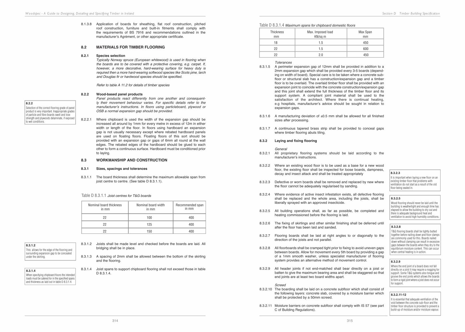
Section D T imber Building SpecificationWoodspec - A Guide to Designing, Detailing and Specifying T imber in Ireland
314
8.1.3.8 Application of boards for sheathing, flat roof construction, pitched roof construction, furniture and built-in fitments shall comply with the requirements of bS 7916 and recommendations outlined in the manufacturer’s Agrément, or other appropriate certificate.
8.2 MATERIALS FOR TIMBER FLOORING
8.2.1 Species selectionTypically Norway spruce (European whitewood) is used in flooring when the boards are to be covered with a protective covering, e.g. carpet. If, however, a more decorative, hard-wearing surface for heavy duty is required then a more hard-wearing softwood species like Scots pine, larch and Douglas fir or hardwood species should be specified.
Refer to table A 11.2 for details of timber species
8.2.2 Wood-based panel productsPanel products react differently from one another and consequent-ly their movement behaviour varies. For specific details refer to the manufacturer’s instructions. In floors using particleboard, plywood or OSB a normal expansion gap should be provided.
8.2.2.1 where chipboard is used the width of the expansion gap should be increased all around by 1mm for every metre in excess of 12m in either width or length of the floor. in floors using hardboard an expansion gap is not usually necessary except where rebated hardboard panels are used on floating floors. floating floors of this sort should beprovided with an expansion gap or gaps of 6mm all round at the wall edges. the rebated edges of the hardboard should be glued to each other to form a continuous surface. hardboard must be conditioned prior to laying.
8.3 WORKMANSHIP AND CONSTRUCTION
8.3.1 Sizes, spacings and tolerances
8.3.1.1 the board thickness shall determine the maximum allowable span from joist centre to centre. (See table d 8.3.1.1).
Table D 8.3.1.1 Joist centres for T&G boards
Nominal board thickness in mm
Nominal board width in mm
Recommended spanin mm
22 100 400
22 125 400
22 150 400
8.3.1.2 Joists shall be made level and checked before the boards are laid. All bridging shall be in place.
8.3.1.3 A spacing of 2mm shall be allowed between the bottom of the skirting and the flooring.
8.3.1.4 Joist spans to support chipboard flooring shall not exceed those in table d 8.3.1.4.
Thickness Max. Imposed load Max Span mm KN/sq m mm
18 1.5 450
22 1.5 600
22 2.0 450
Table D 8.3.1.4 Maximum spans for chipboard domestic floors
Tolerances8.3.1.5 A perimeter expansion gap of 12mm shall be provided in addition to a
2mm expansion gap which shall be provided every 3-5 boards (depend-ing on width of board). Special care is to be taken where a concrete sub-floor or structural slab has a construction/expansion gap and a timber floor is to be overlaid. the overlaid timber floor shall be provided with an expansion joint to coincide with the concrete construction/expansion gap and this joint shall extend the full thickness of the timber floor and its support system. A compliant joint material shall be used to the satisfaction of the architect. where there is continual heating, e.g hospitals, manufacturer’s advice should be sought in relation to expansion gaps.
8.3.1.6 A manufacturing deviation of ±0.5 mm shall be allowed for all finished sizes after processing.
8.3.1.7 A continuous tapered brass strip shall be provided to conceal gaps where timber flooring abuts tiling.
8.3.2 Laying and fixing flooring
General8.3.2.1 All proprietary flooring systems should be laid according to the
manufacturer’s instructions.
8.3.2.2 where an existing wood floor is to be used as a base for a new wood floor, the existing floor shall be inspected for loose boards, dampness, decay and insect attack and shall be treated appropriately
8.3.2.3 defective or worn boards shall be removed and replaced by new where the floor cannot be adequately regularised by sanding.
8.3.2.4 where evidence of active insect infestation exists, all defective flooring shall be replaced and the whole area, including the joists, shall be liberally sprayed with an approved insecticide.
8.3.2.5 All building operations shall, as far as possible, be completed and heating commissioned before the flooring is laid.
8.3.2.6 the fixing of skirtings and other similar finishing shall be deferred until after the floor has been laid and sanded.
8.3.2.7 flooring boards shall be laid at right angles to or diagonally to the direction of the joists and not parallel.
8.3.2.8 All floorboards shall be cramped tight prior to fixing to avoid uneven gaps between boards. Allow for movement every 5th board by providing a gap of a 1mm smooth washer, unless specialist manufacturer of flooring system provides an alternative method of movement control.
8.3.2.9 All header joints if not end-matched shall bear directly on a joist or batten to give the maximum bearing area and shall be staggered so that end joints are at least two board widths apart.
Screed8.3.2.10 the boarding shall be laid on a concrete subfloor which shall consist of
the following layers: concrete slab, covered by a moisture barrier which shall be protected by a 50mm screed.
8.3.2.11 moisture barriers on concrete subfloor shall comply with iS 57 (see part c of building regulations).
8.3.1.2
This allows for the edge of the flooring andsurounding expansion gap to be concealedunder the skirting.
8.3.1.4When specifying chipboard floors the intendedloads must be catered for in the specified spansand thickness as laid out in table D 8.3.1.4.1
8.3.1.2
This allows for the edge of the flooring andsurounding expansion gap to be concealedunder the skirting.
8.3.1.4When specifying chipboard floors the intendedloads must be catered for in the specified spansand thickness as laid out in table D 8.3.1.4.1
8.2.2
Selection of the correct flooring grade of panelproduct is very important. Inappropriate gradesof particle and fibre boards swell and losestrength and plywoods delaminate, if exposedto wet conditions.
8.3.2.5
Wood flooring should never be laid until thebuilding is weathertight and enough time haselapsed to allow the building to dry out andthere is adequate background heat andventilation to avoid high humidity conditions.
8.3.2.3
It is important when laying a new floor on anexisting timber floor that problems withventilation do not start as a result of the oldfloor being sealed in.
8.3.2.8
T&G flooring boards shall be tightly buttedtogether before nailing down and floor clampsare commonly used for this. Boards naileddown without clamping can result in excessivegaps between the boards when they dry to theequilibrium moisture content. This can occurwhen central heating is in action.
8.3.2.9
Where the end joint of a board does not falldirectly on a joist it may require a nogging forsupport. Some T&G systems also tongue andgroove the end joints which allows the boardsto form a rigid joint where a joist does not occurfor support.
8.3.2.14
Before new flooring is laid, any unevennessshall be eliminated. One way of accommodatingsome limited unevenness, is the use of anunderlay or other form of resilient layer.
8.3.2.11-12
It is essential that adequate ventilation of thevoid between the concrete sub-floor and thetimber floor structure is provided to prevent abuild-up of moisture and/or moisture vapour.
315
Section D T imber Building Specification
317
Woodspec - A Guide to Designing, Detailing and Specifying T imber in Ireland
316
8.3.2.12 the screed shall be allowed to dry to a maximum moisture content of 5% as measured by the method described in bS 8201.
8.3.2.13 in accordance with bS 8201, if there is any question about the dryness of the screed, a damp-proof membrane shall be applied before the floor is laid.
8.3.2.14 the concrete or screed base shall be adequately flat and level (maximum 2mm gap under a 2m straight-edge).
Softwood flooring8.3.2.15 boards shall be face nailed to every joist or batten.
8.3.2.16 boards up to and including 125 mm wide shall be fixed at a minimum of 15mm from the board edge using two nails, or secret nailed if tongued and grooved.
8.3.2.17 lost head nails shall be punched below the surface.
8.3.2.18 Screws shall be used for fastening boards over electric cables, over pipework and in particular over junction boxes to which access may be needed.
8.3.2.19 Screws shall be countersunk and (except at access points) all holes should be pelleted with matching timber.
8.3.2.20 tongued and grooved boards of 100mm or less in width shall be secret nailed through the tongued edge at each intersection with a joist or batten in order to minimise disfiguration.
Hardwood FlooringLaying hardwood floors is generally considered to be a specialist job and it is recommended that these floors are always laid by a specialist hardwood flooring contractor.
Strip Flooring8.3.2.21 hardwood strip flooring shall be secret nailed through the tongue into the
battens or joists.
8.3.2.22 the boards shall be laid in random lengths with the board ends staggered; no board to be left floating between the joists; each board to be supported by at least one batten or joist.
Hardwood Block Flooring8.3.2.23 hardwood blocks shall be laid from the centre line outwards.
8.3.2.24 the underside of each individual block shall be dipped in adhesive and placed in position without undue sliding.
Mosaic fingers8.3.2.25 the panels shall be laid from the centre line outwards.
8.3.2.26 when applying paper-faced mosaic, the paper shall be removed from the surface as the work proceeds.
Parquet8.3.2.27 overlay shall be fixed by secret pinning to a wood base through the
tongue.
8.3.2.28 proprietary systems of engineered parquet and overlay shall be laid in accordance with the manufacturer’s instructions.
8.3.2.29 end joints between panels shall be staggered transversely across the floor, all longitudinal joints shall be in line.
Battens8.3.2.30 battens shall be laid at maximum centres of 400mm (detail b 9.2.3).
8.3.2.31 General
flooring shall not be laid until all wet trades are completed, the plaster and concrete dry and the heating is switched on.
8.3.3 Metal fixings
8.3.3.1 care shall be taken to ensure compatibility of metal fixings when used with preservative treated timber.
8.3.3.2 nails and pins shall comply with the requirements of bS 1202: part 1.
8.3.3.3 collated flat nails used for secret nailing of floor boards shall be 2.5 times the thickness of the flooring board. in the case of thin sheet materials ring shank or serrated nails may be used when the minimum penetration into the timber support base shall be 19mm.
Screws 8.3.3.4 Screws shall be not less than size no. 8 and shall have a length of at
least twice the thickness of the flooring being fixed, except in the case of thin sheet materials when the minimum penetration into a timber base shall be 19mm to comply with bS 1210.
Floor Clips8.3.3.5 floor clip systems vary from one manufacturer to the next. when
installing a floor using this type of system, as with any other proprietary system, the floor shall be installed according to the manufacturer’s instructions.
8.3.4 Adhesives
8.3.4.1 parquet panels or parquet flooring (other than proprietary materials for which the manufacturer’s recommendations advise otherwise) shall be fixed to concrete using a cold adhesive complying with the requirements of either bS 1204 or bS 4071.
8.3.4.2 the adhesive shall be spread evenly on mosaic fingers using a serrated trowel.
Serrations shall be u-shaped, measuring 3mm deep by 3mm wide, and be spaced at 8mm centres. Serrations shall be maintained accurately to size in order that the correct amount of adhesive is applied.
8.3.4.3 Adhesive shall be applied to no more than 4m2 of the base of the flooring at any one time.
8.3.4.4 the panels shall be bedded firmly in the adhesive with the edges tightly butted to form a continuous pattern.
8.3.4.5 complete adhesion shall be obtained by pressing down with a roller weighing about 65Kg or by other suitable means within 30 min of being laid.
8.3.4.6 engineered overlay shall be spot glued on the side tongues and grooves and where ends match.
8.3.2.17
Where a more decorative finish is requiredboards under 100mm in width can be secretnailed.
8.3.2.18
This clause only applies when square edgedfloor boards are used.
8.3.2.17
Where a more decorative finish is requiredboards under 100mm in width can be secretnailed.
8.3.2.18
This clause only applies when square edgedfloor boards are used.
8.3.2.9
Where the end joint of a board does not falldirectly on a joist it may require a nogging forsupport. Some T&G systems also tongue andgroove the end joints which allows the boardsto form a rigid joint where a joist does not occurfor support.
8.3.2.14
Before new flooring is laid, any unevennessshall be eliminated. One way of accommodatingsome limited unevenness, is the use of anunderlay or other form of resilient layer.
8.3.2.11-12
It is essential that adequate ventilation of thevoid between the concrete sub-floor and thetimber floor structure is provided to prevent abuild-up of moisture and/or moisture vapour.
8.3.2.22
Hardwood strip flooring is usually end matchedwhich enables boards to be joined at any stage,thereby eliminating wastage as boards donot need to be cut so as to join over a joistor batten.
8.3.2.23
Blocks are laid in this fashion until they reachthe perimeter where an expansion gap is left.The centre line is defined as the line dividingthe narrowest width of the area to be covered
8.3.2.26
The paper may need to be damped to facilitateits removal during this procedure. If paper isnot removed until later it may prove difficultwhen scuffed and walked into the timber.
8.3.2.27
This is usually a thin boarding approximately8mm to 12mm thick tongued and groovedwith ends matched.
8.3.3.3
Normal or improved nails may be either handdriven or machine applied. The greater holdingpower of improved nails much increasesresistance to ‘nail-popping’ but may add to therisk of the wood splitting.
8.3.4.3
This enables the panels to be beddedaccurately and firmly into position before theadhesive dries .
8.3.5.2
This only applies if the boards are to be leftexposed.

Section D T imber Building Specification
319
Woodspec - A Guide to Designing, Detailing and Specifying T imber in Ireland
318
8.3.5 Surface coatingsThe choice of the initial surface treatment and subsequent mainte-nance procedures depends on the type of building and wood, nature of occupancy and traffic, availability and efficiency of staff and equipment for initial treatment and maintenance.
Seals (such as lacquers) penetrate wood, reinforce its structure and leave a protective coat on its surface. Once sealed this way, the floor surface needs comparatively little maintenance. Eventually the seal will wear and the wooden flooring must then be re-treated, before the wood is exposed, to avoid the need to resand the floor. Some proprietary systems have a pre-oiled finish which needs weekly maintenance, but does not need re-sanding.
8.3.5.1 hardwood strip and board flooring shall be sanded and finished with a seal. the boards shall be either wax polished or given an oil treatment.
8.3.5.2 Softwood strip flooring shall be sanded and finished with a seal. Subsequently, it shall be either wax polished or given an oil treatment.
8.3.5.3 All seals shall be applied in accordance with bS 8201
8.3.5.4 Seals used in flooring shall be one or two part polyurethane. two-part polyurethane is the hardest wearing finish.
8.3.5.5 Any surface irregularities e.g. cupping, unevenness or sharp edges shall be removed by a light sanding.
8.3.5.6 A primer shall be compatible with the seal. one coat of primer shall be applied after sanding followed by the seal coat.
8.3.5.7 the primer shall be quick drying, easy to apply and shall not discolour the flooring.
8.3.5.8 A liquid wax compatible with the selected finish shall be applied immediately after laying the blocks.
8.3.6 Site protectionAbsorption of moisture on-site causes swelling. In order to avoid the damage from this as well as from grit, soiling and spillages, the floorboards should be laid as late as possible in the construc-tion stage. It is also important to prevent wood shavings and other debris from accumulating under a floor as this may lead to a fire hazard or to infestation by vermin.
8.3.6.1 in compliance with bS 8201, all materials on-site intended for flooring shall be stacked carefully to retain flatness.
8.3.6.2 materials shall be stored in a warm (approximately 10°c to 20°c), dry environment under conditions that will maintain the moisture content at the level recommended for laying.
8.3.6.3 delivery shall be programmed to ensure the shortest possible storage period.
8.3.6.4 the moisture content of timber and wood products shall be checked immediately upon receipt on site.
8.3.6.5 once the flooring is laid it shall be kept clean and free from cement, plaster droppings and other debris likely to cause damage.
8.3.6.6 trestles, ladders or steps which shall be used on a laid floor shall have protective padding.
8.3.6.7 use hardboard as a temporary protective surface to laid floor until handover of project.
8.4 PERFORMANCE SPECIFICATIONS
8.4.1 Quality and classificationIn order to ensure the quality of the floor it should be checked upon delivery, during construction and hand-over.
All wood flooring shall be free from:(a) rot or mould staining.(b) active insect attack.(c) natural and drying defects that detract from the suitability of the
flooring, e.g. excessive splits and shakes.(d) loose knots or knot holes.
8.4.1.2 All work shall be inspected whilst in progress and after completion, special attention being paid to the possibility of defects.
8.4.1.3 timber shall be inspected on its arrival for defects.
8.4.2 Moisture content The importance of using wood at correct moisture content cannot be over-emphasised. If, at the time of fixing the moisture content is too great, shrinkage is inevitable, which results in unsightly open joints; if the moisture content is too low, swelling may occur result-ing in bowing, lifting and buckling. When heating is applied to occu-pied buildings the relative humidity reduces and the moisture content of the timber responds by decreasing. Buildings that are suddenly heated on occupation will result in surface shrinkage, differential stress and distortion of the timber work. It is very impor-tant to gradually heat, control humidity and condition the interior spaces to their design/comfort conditions. When the design condi-tions are achieved and remain constant, the timber will reach an equilibrium state compatible with the ambient relative humidity. Timber species vary in their lateral shrinkage on drying and their movement (expansion and contraction with increase or decrease in atmospheric humidity). They range from small (up to 1.5%) to large (3+%) movement and it is important to know the movement rating of the selected species and allow accordingly.
Unheated building 17±2%
Intermittent heating with a substantial dropin temperature between periods of heating 12±2%
Continuous heating with the temperaturemaintained day and night throughout theyear at a reasonably constant level 10±2%
Under-floor heating 7±1%
Table D 8.4.2.1 Average moisture content of floor boarding in service (BS 8201).
8.4.2.1 the moisture content at delivery and installation on site shall be in accordance with the in-service percentages listed in table d 8.4.2.1.
8.4.2.2 timber shall be checked for moisture content using an electrical moisture meter.
8.4.2.3 floor boarding shall be laid only when the heating system is operating and the building has fully dried out.
8.4.3 Fire
8.4.3.1 timber floors shall comply with the building regulations part b.
8.3.5.4
One-part seals have advantages on a buildingsite because they are ready to use. Seals usedin newly installed floors may produce ‘fissurecracking’. Careful and regular maintenance willretard the rate of surface wear of a timber. Thedegree of retardation depends on the surfaceconditions and the type of finish. Epoxy finishesare the hardest wearing.
8.3.4.3
This enables the panels to be beddedaccurately and firmly into position before theadhesive dries .
8.3.5.2
This only applies if the boards are to be leftexposed.
8.3.5.6
Where it is desired to treat new flooring woodblocks and mosaics before the moisture contenthas reached equilibrium with its surroundingsone of the following methods of pre-treatmentmay be considered:
• Pre-treatment by the use of a special primer.
• Pre-treatment by the use of a thin liquidwax.
8.3.5.8
After the wax is applied the floor is then sandedin the normal manner. This removes the waxfrom the surface, leaving the wax only betweenthe joints of the flooring. The wax prevents theseal hardening in the joints and thus preventsadhesion.
8.3.6.4
If the timber is well protected by moisture-resistant wrapping, its moisture content shouldalso be checked when unwrapped.
8.3.6.5
As the flooring is laid, it should be protectedprogressively with polyethylene sheets or othersimilar material and scaffold boards shouldbe placed over it to reduce the risk of slipping.
Flooring should be maintained by backgroundheat and ventilation in a low relative humidityenvironment. In order to avoid over-stressingthe timber, the heating should be brought upslowly to the required temperature.
8.4.2
For underfloor heating, a low moisture contentis essential. Boards at a moisture content of6% to 8% are available by special order onlyand as such they require special attention instoring and laying. The manufacturer shouldgive instructions on how to handle these boards.
Section D T imber Building Specification
321
Woodspec - A Guide to Designing, Detailing and Specifying T imber in Ireland
320
8.4.4 Preservative treatments Consideration should be given to the pre-treatment of flooringtimber and its support system (if any), to ensure adequate durabil-ity. See Section A4 for additional advice and detail with regard to potential hazard classes and possible preservative treatments. For example, softwood flooring laid on suspended timber ground floors, or on ground floor concrete slabs, require treatment to Use/Hazard Class 2, whereas similar floor construction above ground floor level would be treated to Use/Hazard Class 1.
8.4.4.1 All boarding shall be kept clear of masonry walls, to protect from dampness and condensation.
8.4.4.2 timbers to be used in ground floors, suspended or laid on concrete slab, shall be deemed to fall into use/hazard class 2 and be treated accordingly.
8.4.4.3 timber floors above ground floor level shall be deemed to fall into use/hazard class 1 and therefore do not require specific preservative treatment.
8.5 GENERAL
8.5.1 Compliance
8.5.1.1 Aspects of flooring shall comply with the following codes and standards, as relevant:
bS1297: tongued and grooved softwood flooring.bS 8201: code of practice for flooring of timber, timber products and
wood-based panel products.bS5268: code of practice for permissible stress, (part 2) design,
materials and workmanship.
8.5.2 Architect’s requirements
8.5.2.1 floors shall comply with architect’s requirements or where otherwise stated with manufacturer’s or supplier’s requirements.
D 9 Joinery
9.1 JOINERY ELEMENTS
9.1.1 GeneralThe uses of joinery vary considerably, for example, doors may require different specifications depending on use, e.g. fire-resisting door or an external door. Furthermore, the frequency of use has implications for the design and specification and the potential of abuse has to be catered for. Different environmental aspects also play a part in the specification of joinery. In this section we deal with both internal and external joinery.
9.1.1.1 timber sections shall be designed to withstand dead loads, mainly the weight of glass and applied loads, which is the wind pressure/suction coupled with sudden impact loads.
9.1.1.2 exterior joinery shall be protected from the elements before and during the construction.
9.1.2 Windows Timber window design is a specialised area necessitating good practice, proper detailing and performance testing before the launch of a durable and efficient product. There are many propri-etary systems on the market so it is advisable to deal with a reputable manufacturer who has a proven track record and whose products have been independently tested and certified. It is impor-tant that proprietary systems are specified in accordance with manufacturers’ instructions so as to ensure their optimum perform-ance. At the design stage there are certain aspects of glazing which must be kept in mind. Orientation greatly influences the comfort conditions of a building. In some cases exposure to too much suncan create unwanted heat energy. Reflective or tinted glazing will help reduce over-heating. Another important aspect of glazing is thermal insulation, as a large proportion of the total heat loss of a building is through windows. Heat transmittance from the interior heated environment can be reduced by increasing the performance of the glazing system. The thermal transmittance of single glazing is very high (U-value 5 W/m2K), standard double glazing will reduce this heat loss to a U-value of 3 W/m2K approx. High-performance energy-efficient double glazing, with a wide cavity (24mm), Argon-gas filled, and low emissivity reflective coating on the inner surface of the outer pane, will reduce the energy loss to approx. 1.4 W/m2K. This is less than one third of the heat loss of single glazing and per-forms better than standard triple glazing. Skilled Irish joinery workshops can produce bespoke small and large-scale windows, glazed screens, doors and stairs to architectural detail design drawings.
9.1.2.1 timber in main frames and casements shall be European redwood, Douglas fir, Scots pine or larch, complying with J10 of en 942. timber glazing beads to comply with class J2. laminating of sections is permitted. finger jointing of individual laminates is permitted, but not of whole sections nor on exposed surfaces intended for a clear or stain finish. inserts and fillers are not permitted. there should be no signs of active insect attack; pinhole borer holes on exposed surfaces are not permitted. moisture content of timber at the time of installation is to be 16%. Adhesives shall comply with the requirements of class d4 of en 204.
9.1.2.2 All windows shall be fitted according to manufacturer’s instructions.
9.1.2.3 the structural openings shall not measure more than 16mm larger than the size of the unit, allowing joints of 8mm to 15mm.
9.1.2.4 Joints between the structure and frame shall be packed with wood woolwadding and covered with an elastic weather seal mastic.
9.1.2.5 weather drips shall be cut in to the underside surface of horizontal planes.
9.1.2.6 A water channel shall be grooved into the top and sides of the opening section.
9.1.2.7 the top of horizontal members exposed to weather shall have a run-off slope of at least 1:8.
9.1.2.8 glass shall be bedded in mastic - 2mm thick - between the timber rebate and the glass.
9.1.2.9 glazing sprigs shall be non-corroding and fitted at max. 400mm centres.
9.1.2.10 timber glazing beads shall be double-vacuum treated with preservative in accordance with bS 8417 and manufacturers instructions and fixed with non-ferrous panel pins or screws at 200 mm maximum centres and not more than 50 mm from each corner.
9.1.2.11 glazing beads shall not be mitred but the top and bottom beading shall run full width and be bedded in mastic with the vertical beads cut to fit.
9.1.1.1The strength required of external joinery willdepend on the following:• Exposure condition to wind loads• Size of glazed area• Pressure exerted by people in the form of
vertical or horizontal loads• Weight of glass (if applicable) to be
supported• Accidental loads
9.1.2.1
This is a sample specification only. An alternativespecies may be selected from table A 12.1. Theclass of timber is explained in D 9.4.1.
Plugs to replace knots are permitted aslong as they are of the same timber with thedirection of the grain matched.
9.1.2.8 Glazing Beads
A 2mm-thick bedding mastic shall be placedbetween the glass and the bead to seal. The bottombead shall be raised on spacers (200 mm centres)to allow drainage and ventilation and this beadshall be tapered to fall and extend beyond the faceof the timber cill to weather same.

Section D T imber Building Specification
323
Woodspec - A Guide to Designing, Detailing and Specifying T imber in Ireland
322
9.1.2.12 laminating of sections is permitted and advisable. finger jointing of individual laminates is permitted, but not of whole sections. Splits, shakes, checks and plugs are to comply with the requirements of J10 of en 942. fillers are not permitted. plugs of the same material (to replace knots) are permitted.
9.1.2.13 At least one opening sash shall be provided in all habitable rooms of residential buildings. this window shall provide an unobstructed opening not less than 850x500 mm. the bottom of any such window shall be not less than 600mm nor more than 1100mm from the floor of the room in which it is situated. Safety glazing shall be installed in accordance with current guidelines.
9.1.2.14 openings shall be securable and their size shall be adjustable.
9.1.2.15 trickle vents for controlled permanent ventilation shall be fitted to the top horizontal member of the fixed frame.
9.1.2.16 the joiner shall ensure that all weathering surfaces, throatings, grooves, open joints etc. shall be properly executed to specification and shall function as a weathertight element.
9.1.3 DoorsExternal door-faces are exposed to significantly different interior/exterior environmental conditions on both surfaces. This causes differential movement resulting from differences of humidi-ty, temperature, and dampness on either surface. Resulting swelling and shrinkage may cause doors to twist and create gaps, allowing rain and draughts to penetrate. Care should be taken to shelter, weather and protect exterior doors, thereby minimising dis-tortion. As with windows, specialist advice should be sought in the design, specification and installation of doorsets.
Internal doorsets9.1.3.1 internal panel doors shall be 1981x762x45mm thick. Scots pine to
class J10 of en 942. glazing beads shall match and shall be supplied loose. door frames and linings shall be rebated and sized to suit finished wall thickness. moisture content shall be 12% ± 2% at time of manufac-ture and delivery to site.
9.1.3.2 All doors shall be fitted according to manufacturer’s instructions.
Internal flush doors9.1.3.3 flush doors shall be lipped with solid timber (not less than 6mm thick)
glued along the edges of both stiles, and shall also be lipped on the bottom and top. where the door leaf is supplied pre-fitted, as part of the doorset, the thickness of the lipping shall be reduced to 6mm.
9.1.3.4 blockings shall be provided in hollow core doors to receive special items of hardware, such as mortice locks, overhead closers, security fittings and coat hooks.
9.1.3.5 lock blocks shall be positioned in accordance with iS 196: part 1 and glued or stapled securely to the stiles.
9.1.3.6 the facing shall be 6mm plywood, glued to the core and framework in a suitable press without framing showing through.
9.1.3.7 openings shall be framed in the core, rebated and provided with mitred glazing beads in eight pieces (four each side) loosely pinned to the framing. the glazing beads shall be rebated to overlap the edges of the facings by at least 3mm.
9.1.3.8 A solid core door shall consist of a suitable core of solid timber, covered on both sides with facings of plywood or other suitable material, with or without appertures for glazing or ventilation louvres.
External Doors9.1.3.9 All metal fixings to external doors shall be corrosion resistant, durable
and sufficiently strong and suitable for their intended exposure conditions and usage. the door-locking mechanism shall be three point to eliminate warp and provide additional security.
9.1.3.10 frames shall be wedged and securely fixed with metal fasteners at the level of the top hinge, lock (intermediate rail) and bottom.
9.1.3.11 glass shall be a minimum of 6mm plate (tempered) glass, preferably laminated and shall be double glazed for external doors or sound insulating doors.
9.1.3.12 Stiles and rails shall be jointed with stub-tenons or mechanical devices. the framework shall be square when assembled, in a true plane, and the parts shall match each other in thickness.
9.1.3.13 the framework of flush doors shall be ventilated by means of a 5x5mm groove in each stile or four 6mm diameter holes in each rail to give a total area of 100mm2.
9.1.3.14 door frames shall be secured by non corrosive screws or specialist proprietary fixings in accordance with manufacturer’s instructions.
9.1.4 Staircases
9.1.4.1 Strings, handrails, balustrades, newels and risers shall be Scots pine (european redwood). treads shall be of mdf. timber quality shall conform to J30 of en942. Sizes and tolerances shall comply with bS 585: part 1. workmanship shall be in accordance with bS 1186: part 2. Adhesive shall comply with en 204 type d3 or d4. the moisture content at time of manufacture and delivery on site shall be 12%±2%.
9.1.4.2 Staircases, landings and galleries shall comply with bS 585
9.1.4.3 Staircases shall be constructed according to detail drawings.
9.1.4.4 treads, risers, balusters, handrails and newel posts shall be sanded smooth, end-grain chamfered and finished with specified resin/lacquer finish.
9.1.4.5 landings, balusters, handrails, and step rise and going to comply with the current building regulations for their respective end use.
9.1.4.6 treads, risers and strings shall be housed into the newel posts.
9.1.4.7 handrail shall be mounted to form a continuous rail, curved if necessary at junctions, and dowelled at joints.
9.1.4.8 part m tgd shall be complied with for handrails, tread alert and visual definition.
9.2 MATERIALS FOR INTERNAL AND EXTERNAL JOINERY
9.2.1 Timber species selection
choose from table A 12.1: Joinery species suitability.
9.1.2.12
Laminating sections can provide greaterstability to the components. The practicerequires care and proper quality control.
9.1.2.13 Safety
This specification is in accordance with BS5588: Part 1: 1990 and Building Regulations1997 Part B1.5.1.7.
Windows in upper floor levels shall be at least900mm above floor level to guard againstchildren falling through glass or openings.Where windows are fitted below this level, theyshall be fixed-lights or fitted with a child-prooflock or guarded with a rail or balustrade. Theglass shall be a minimum of 6 mm plate orlaminate glass.
9.1.2.15 Trickle Vents
This specification is only applicable wherethis type of permanent ventilation is desired.Vents are normally listed as an additionalfeature to most proprietary systems.
9.1.3
Duty performance is graded:
Light duty (LD), Medium duty (MD), Heavyduty (HD) and Severe duty (SD)
9.1.3.1
This is a sample specification only. Sizesshould be referred to the manufacturer’sstandard sizes.
9.1.3.3
A solid core door performs better than a hollowcore door with regard to fire resistance, soundinsulation and structural strength.
9.1.3.1
This is a sample specification only. Sizesshould be referred to the manufacturer’sstandard sizes.
9.1.3.3
A solid core door performs better than a hollowcore door with regard to fire resistance, soundinsulation and structural strength.
9.1.4.1
This is a sample specification only. Wheretreads are to be exposed and left finished, theyshould be of hardwood such as oak, ash orbeech or iroko and fitted with slip resistingedgings or propietary carborundum strips.Alternative species, and adhesives may beselected from the following sections
Species Table A 12.1
Adhesive D 9.2.3
Panel products, particularly MDF, are beingincreasingly used in stair manufacture due to:
• limited availability of boards of adequatewidth;
• uniformity of product;
• ease of machining

Section D T imber Building Specification
325
Woodspec - A Guide to Designing, Detailing and Specifying T imber in Ireland
324
9.2.2 Wood-based panel products
Plywood9.2.2.1 plywood shall generally comply with en 636. All plywood shall be first
grade and shall be faced with veneer as specified. one side shall be completely free from joints and surface defects. Joints and minor blemishes will be permitted on the reverse side only. where both sides of the plywood are exposed these shall be totally free of joints and surface defects.
OSB9.2.2.2 oSb shall comply with en 300
Chipboard 9.2.2.3 chipboard shall comply with en 312
Fibreboard 9.2.2.4 mdf shall comply with en 622.
Blockboard9.2.2.5 blockboard shall comply with bS 3444 grade ii veneer or with facing
veneer as described.
Wood veneers9.2.2.6 wood veneers shall be prime quality rotary birch and quarter-sawn
oak, a sample of which shall be submitted and approved by the architect. the architect is to be informed when the whole of the stock is ready for his inspection and approval before work is commenced.
9.2.3 AdhesivesThe following two specifications give alternate approaches to specifica-tion of adhesives, the second one being more specific than the first.
9.2.3.1 types and applications of adhesives for all framed, glued joints, finger joints and laminated timber shall comply with bS 1186: part 2 and should be compatible with wood preservatives, if so required.
9.2.3.2 Adhesives shall comply with the appropriate class of en 204.
9.2.4 Screws and nails
9.2.4.1 Screws shall comply with bS 1210 and nails with bS 1202. in every case the size and material of screws and nails shall be specified as appropriate to the nature of the fixing and of the materials involved. Screws, nails or metal fastenings in hazardous locations or conditions must be non-ferrous, e.g. stainless steel, silicon bronze. no other screws or nails permitted. the fixing of external cladding, joinery or window beads with non stainless steel or silicon bronze screws, nails or fixing pins will be rejected.
9.3 WORKMANSHIP AND CONSTRUCTIONTo minimise damage from moisture movement due to humidity (swelling during construction, shrinkage and distortion later), it is advisable that doors be fitted after completion of building construction when the heating system is in operation and all wet trades are completed.
9.3.1 Jointing, fitting and fixingThe assembly of worked timber components can be off-the-shelf mass-produced items, custom-made in a joinery workshop, or assembled on-site. It is advisable that they be made under controlled conditions in a joinery workshop wherever possible.
9.3.1.1 workmanship shall be in accordance with bS1186: part 2.
9.3.1.2 Any plug or insert shall be as follows:• of the same species as the surrounding timber;• well secured by a mr or wbp adhesive;• occupy the full depth and surface area of the hole;• lie with its grain in the same general direction as the grain of the piece
into which it is inserted;• be of width, i.e. the lesser dimension not greater than 6mm
above the maximum limit of knot size for the specified surface category.
9.3.1.3 Any filler shall completely fill the hole, shake or check and shall be a timber filler compatible with the intended end-use of the timber.
9.3.1.4 laminated, finger-jointed, edge-jointed timbers are acceptable in joinery, subject to compliance with bS 1186: part 2.
9.3.1.5 where a solid timber panel is fitted into grooves, the following requirements shall apply:• the grooves shall be no less than 9mm deep.• the faces of the panel shall fit closely to the sides of the grooves.• in the direction of the grain, the length of the panel shall be shorter
than the distance between the bottoms of the grooves, by no more than 3mm.
• Across the grain, the panel shall be less than the distance betweenthe bottoms of the grooves to provide for expansion and contraction.
• the panel shall not be fixed in any way that will prevent its free expansion and contraction.
• profiled boarded surfaces, such as tongued and grooved and rebated joints, shall comply with the requirements of bS 1186 part 2.
• fixed joints including doweled, mortised and tenon, combed, halving and dovetail joints shall comply with bS 1186: part 2.
9.3.1.6 Jointing of framework shall be mortice and tenoned and glued to comply with iS 196: part 6.
9.3.2 Tolerances
9.3.2.1 Allowable tolerances for the installation of doorsets:• clearance between leaf and jamb/head/transom: 2mm (+1mm,- 0.5mm)• clearance between leaf and cill/saddle: 3mm (+1mm,-0.5mm)
9.3.2.2 the deviation from squareness (at a point 500mm from any corner) shall not exceed 0.75mm.
9.3.2.3 flatness• the maximum permitted distortion for bow (along the length) and cup
(across the face) is 2mm.
9.3.2.4 local flatness: • 0.2mm when measured on a 50mm base, 0.6mm when measured on
a 200mm base. • tolerance for movement: 1.5mm at each junction of door leaf and
fixed frame.
9.3.3 Site protectionThe protection of joinery during transport, storage and after its fitting has to be carefully considered and provided for. The incom-plete, often damp building environment can lead to swelling and deformation of timber, often followed by shrinkage stresses. Cement splashing and other damage risks can cause staining or breakage. Protective coatings or appropriate wrappings should therefore be applied in the fabrication workshop. If this is not done, a protective covering should be applied immediately on site. This will also retard the rate of moisture uptake on site.
9.2.2.3
There are many types of MDF. See DesignGuidance A9.3 for further details.
9.2.2.5
There are five principal veneer cutting methodsnamely, rotary, flat slicing, quarter slicing, rift-cut and half-round slicing. Don’t just specifyveneer as the different cutting methods willproduce different visual effects, depending onhow the log is cut (Ref. ‘Saw to Site’.)
9.3.1.5
Never glue solid timber panels in place.

Section D T imber Building Specification
327
Woodspec - A Guide to Designing, Detailing and Specifying T imber in Ireland
326
9.3.3.1 the timber work shall be coated with wood stain before being fitted.
9.3.3.2 Staircase and other joinery elements shall arrive as late as possible on site.
9.3.3.3 Staircases, especially treads, shall be protected from construction traffic.
9.3.3.4 All joinery elements shall be protected from exposure to humidity and dampness until completion of construction.
9.3.3.5 All joinery elements shall be protected from exposure to damage (splashing, grit, staining, indenting, marking).
9.3.4 Surface preparation
9.3.4.1 All woodwork to be painted shall be knotted, stopped, primed and painted with two undercoats and one finishing coat.
9.3.4.2 before fixing woodwork, all surfaces which will be visible after fixing shall be rubbed down and all knots and resin pockets shall be scorched back and coated with knotting. After priming and fixing, all nail holes and other imperfections shall be stopped and the whole surface shall be rubbed down and all dust brushed off.
9.3.4.3 All holes and other imperfections in wood surfaces to receive a clear finish shall be stopped and the whole surface shall be rubbed down and all dust brushed off.
9.3.4.4 Knotting/stopping for external timber work shall be white paste com- plying with bS 2029 or with bS 217 type 2 and gold size complying with bS 311 and shall be tinted to match the surrounding woodwork.
9.3.4.5 the preparation of all surfaces must be seen and approved by the architect before any coatings are applied.
9.3.5 Surface coatingsSurface coatings to external, exposed faces of timber members are most important for the durability of the wood. Pigmented wood stains are most appropriate for a natural wood finish with ultra-violet protective finish coats. Inside surfaces are less critical and paints, stains and varnishes can be used.
9.3.5.1 unless otherwise directed the surface coating treatment of components shall be as detailed in table d 9.3.5.1
COMPONENT TREATMENT
External cladding, pergola Pigmented microporous finish as per manufacturer’sinstructions, minimum 3 coats
Pigmented microporous finish as per manufacturer’sinstructions, minimum 3 coats
Pigmented microporous finish as per manufacturer’sinstructions, minimum 3 coats
Window joiner
External doors
Internal floors, doors, Sand down; one coat polyurethane primer;architrave, skirting 2 coats of 2 pack polyurethane matt finish
Veneer finishes As above or acid catalysed laquer
Table D 9.3.5.1 Surface Coating Treatments
9.3.5.2 unless otherwise prescribed, all coatings shall be applied by brush. written permission must be obtained from the architect for the application of coatings by spray or roller where not so precribed and if permission is granted such application shall not result in extra cost to the employer.
9.3.5.3 if, by the time the work is to receive the first undercoat, the priming coat has in any way deteriorated or has been damaged, the affected portions, or the whole if necessary, shall be rubbed down and reprimed. in the case of articles primed at works, the priming shall be touched up where required with a similar primer.
9.3.5.4 All exterior coatings shall be vapour-permeable to allow vapour to migrate and prevent moisture becoming trapped in the timber behind the coatings.
9.3.5.5 priming paint shall be lead free and comply with bS 4756 or bS 5082.
9.3.5.6 primer for internal woodwork (other than internal surfaces of external doors, windows and their frames) shall be an approved leadless grey priming paint which shall be compatible with the subsequent coats and obtained from the same maker.
9.3.5.7 All paints, varnishes, and other surface coatings shall be delivered in sound and sealed containers, labelled clearly by the manufacturer, the label or decorated container stating:• type of product• use for which it is identified• brand name, if any• the manufacturer’s batch no.the label shall be a printed one. the batch deliveries shall be dated andused strictly in order of delivery.
9.3.5.8 All materials shall be kept in a dry clean store, protected from frost.
9.3.5.9 the finished surface of the staircase shall be able to withstand indenting and scraping and shall not be liable to become slippy in wet or frosty conditions.
9.4 PERFORMANCE SPECIFICATIONSThe behaviour and performance of an item of joinery depends, amongst other factors, on the choice of species, the grade of timber, moisture content, protective coatings, and maintenance. Detailing and manufacturing can also seriously influence perform-ance and longevity. Most importantly, the performance will depend on the appropriate application. ‘Fitness for intended purpose’ must be clearly defined, and the end-use condition foreseen, and the design, specification, manufacture and installation must carefully accommodate these requirements. Appearance and aesthetics, longevity, hardness, ergonomics, as well as maintenance are all to be considered.
9.4.1 Quality and classification
9.4.1.1 the quality of timber for joinery is subject to the criteria as set out in en 942.
9.4.1.2 Knots to comply with the end use requirements given in en 942.
9.4.1.3 Sapwood is acceptable in joinery. if present in external joinery the timber shall be preservative treated in accordance with bS 8417.
9.4.1The quality of timber is assessed by a systemof grading, expressed in “classes”. As joinerydepends greatly on appearance, it requires theprecise selection of the appropriate class oftimber for its intended use. EN 942 defines fiveclasses of timber for use in joinery.Class J2 and Class JIO are suitable for highquality or specialised joinery. They may requirespecial selection and are usually more costly.Class J2 is not commonly available off-the-shelf in most timber species and needs to beinvestigated before specifying. There are 5classes for exposed surfaces of timber suitablein the use of joinery. These are readily obtainablefrom commercially available grades of softwoodand hardwood.Knots or other surface defects may be acceptabledepending on their location on the finished joineryand class specified. This is a sample specificationonly. The onus is on the designer to specifythe required class of timber
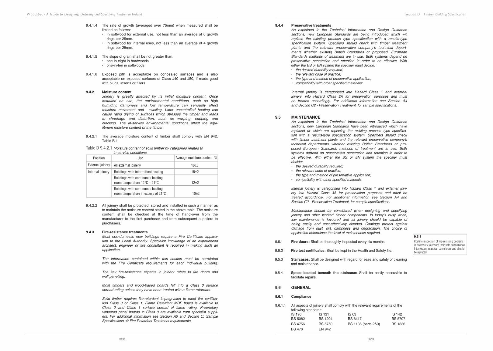
Section D T imber Building Specification
329
Woodspec - A Guide to Designing, Detailing and Specifying T imber in Ireland
328
9.4.1.4 the rate of growth (averaged over 75mm) when measured shall be limited as follows:• in softwood for external use, not less than an average of 6 growth
rings per 25mm.• in softwood for internal uses, not less than an average of 4 growth
rings per 25mm.
9.4.1.5 the slope of grain shall be not greater than:• one-in-eight in hardwoods• one-in-ten in softwoods
9.4.1.6 exposed pith is acceptable on concealed surfaces and is also acceptable on exposed surfaces of class J40 and J50, if made good with plugs, inserts or fillers.
9.4.2 Moisture contentJoinery is greatly affected by its initial moisture content. Once installed on site, the environmental conditions, such as high humidity, dampness and low temperature can seriously affectmoisture movement and swelling. Later uncontrolled heating can cause rapid drying of surfaces which stresses the timber and leads to shrinkage and distortion, such as warping, cupping and cracking. The in-service environmental conditions affect the equi-librium moisture content of the timber.
9.4.2.1 the average moisture content of timber shall comply with en 942, table b.1
Position Use Average moisture content %
External joinery All external joinery 16±3
Internal joinery Buildings with intermittent heating 15±2
Buildings with continuous heatingroom temperature 12°C – 21°C 12±2
Buildings with continuous heatingroom temperature in excess of 21°C 10±2
Table D 9.4.2.1 Moisture content of solid timber by categories related toin-service conditions.
9.4.2.2 All joinery shall be protected, stored and installed in such a manner as to maintain the moisture content stated in the above table. the moisture content shall be checked at the time of hand-over from the manufacturer to the first purchaser and from subsequent suppliers to purchasers.
9.4.3 Fire-resistance treatmentsMost non-domestic new buildings require a Fire Certificate applica-tion to the Local Authority. Specialist knowledge of an experienced architect, engineer or fire consultant is required in making such an application.
The information contained within this section must be correlated with the Fire Certificate requirements for each individual building.
The key fire-resistance aspects in joinery relate to fire doors and wall panelling.
Most timbers and wood-based boards fall into a Class 3 surface spread rating unless they have been treated with a flame retardant.
Solid timber requires fire-retardant impregnation to meet fire certifica-tion Class 0 or Class 1. Flame Retardant MDF board is available to Class 0 and Class 1 surface spread of flame rating. Proprietary veneered panel boards to Class 0 are available from specialist suppli-ers. For additional information see Section A5 and Section C, Sample Specifications, 4: Fire-Retardant Treatment requirements.
9.4.4 Preservative treatmentsAs explained in the Technical Information and Design Guidance sections, new European Standards are being introduced which willreplace the existing process type specification with a results-type specification system. Specifiers should check with timber treatment plants and the relevant preservative company’s technical depart-ments whether existing British Standards or proposed. European Standards methods of treatment are in use. Both systems depend on preservative penetration and retention in order to be effective. With either the BS or EN system the specifier must decide:• the desired durability required;• the relevant code of practice;• the type and method of preservative application;• compatibility with other specified materials;
Internal joinery is categorised into Hazard Class 1 and externaljoinery into Hazard Class 3A for preservation purposes and must be treated accordingly. For additional information see Section A4 and Section C2 - Preservation Treatment, for sample specifications.
9.5 MAINTENANCEAs explained in the Technical Information and Design Guidance sections, new European Standards have been introduced which have replaced or which are replacing the existing process type specifica-tion with a results-type specification system. Specifiers should check with timber treatment plants and the relevant preservative company’s technical departments whether existing British Standards or pro-posed European Standards methods of treatment are in use. Both systems depend on preservative penetration and retention in order to be effective. With either the BS or EN system the specifier must decide:• the desired durability required;• the relevant code of practice;• the type and method of preservative application;• compatibility with other specified materials;
Internal joinery is categorised into Hazard Class 1 and external join-ery into Hazard Class 3A for preservation purposes and must be treated accordingly. For additional information see Section A4 and Section C2 - Preservation Treatment, for sample specifications.
Maintenance should be considered when designing and specifying joinery and other worked timber components. In today’s busy world, low maintenance is favoured and all joinery should be capable of being easily and cost-effectively cleaned. Coatings protect against damage from dust, dirt, dampness and degradation. The choice of application determines the level of maintenance required.
9.5.1 Fire doors: Shall be thoroughly inspected every six months.
9.5.2 Fire test certificates: Shall be kept in the health and Safety file.
9.5.3 Staircases: Shall be designed with regard for ease and safety of cleaning and maintenance.
9.5.4 Space located beneath the staircase: Shall be easily accessible to facilitate repairs.
9.6 GENERAL
9.6.1 Compliance
9.6.1.1 All aspects of joinery shall comply with the relevant requirements of the following standards:iS 196 iS 131 iS 63 iS 142bS 5082 bS 1204 bS 8417 bS 5707bS 4756 bS 5750 bS 1186 (parts 2&3) bS 1336bS 476 en 942
9.5.1
Routine inspection of fire-resisting doorsetsis necessary to ensure their safe performance.Intumescent seals can come loose and shouldbe replaced.