
Wooden Frame Type Instruction Manual - Sugatsune...Upper arm (w/ stopper) (See Fig. on P.5.) Channel...
16
1 Thank you for selecting our product. Before starting installation, please read this manual thoroughly to ensure correct installation. Please keep this manual at hand for future reference. ■ About this product. Lateral swing mechanism hardware that can be installed in narrow "Ideal for tight space applications." ● When placing cabinets next to each other the front will be ● ● It is possible to adjust the door vertically (-3 to +7 mm), horizontally (±7 mm), as well as the depth and angle of tilt. *In order to adjust, make sure that the shelf board can be detached for access. ■ Notes on works Handling of product ● The door is not supplied. ● After unpacking the product, check for damages on the parts. ■For your safety work and operation. well-functioning and safe. warped, since it may affect the movement of the door. If cutting any parts, make sure to remove any burrs before installation. Also check the upper rail for any left-over burrs or scraps and remove these. year is recommended). Caution If not followed injury or damage may result. operate smoothly, and may cause injury. loose screws might result in the door falling and causing injury. Do not try to use this product for anything other than its original purpose. Do not use any part for applications outside of its Do not disassemble nor modify any parts other than those described in this document. WARNING: If these warnings are not followed, it may result in death or serious injury. Prohibited Warning Caution Required Meaning of symbols FAD-44、FAD-44L Wooden Frame Type Instruction Manual R Video Link
Transcript of Wooden Frame Type Instruction Manual - Sugatsune...Upper arm (w/ stopper) (See Fig. on P.5.) Channel...

1
Thank you for selecting our product. Before starting installation, please read this manual thoroughly to ensure correct installation.Please keep this manual at hand for future reference.
■ About this product.Lateral swing mechanism hardware that can be installed in narrow
"Ideal for tight space applications."
●When placing cabinets next to each other the front will be
●● It is possible to adjust the door vertically (-3 to +7 mm), horizontally
(±7 mm), as well as the depth and angle of tilt.*In order to adjust, make sure that the shelf board
can be detached for access.
■Notes on worksHandling of product
● The door is not supplied.● After unpacking the product, check for damages on the parts.
■For your safety work and operation.
well-functioning and safe.
warped, since it may affect the movement of the door.If cutting any parts, make sure to remove any burrs before installation. Also check the upper rail for any left-over burrs or scraps and remove these.
year is recommended).
Caution If not followed injury or damage may result.
operate smoothly, and may cause injury.
loose screws might result in the door falling and causing injury.Do not try to use this product for anything other than its original purpose. Do not use any part for applications outside of its
Do not disassemble nor modify any parts other than those described in this document.
WARNING: If these warnings are not followed, it may result in death or serious injury.
ProhibitedWarningCaution Required
Meaning of symbols
FAD-44、FAD-44LWooden Frame Type Instruction Manual
R
Video Link

2
4 5
1
2
3
6
7
● Description of parts
Hinge base x 2 Channel rail x 1Gas spring nut x 1
Supplied Screw Q'ty
Countersunk self-tapping screw 4x20 5Countersunk self-tapping screw 4.5x30 12
Support arm nut x 1
Clear cushion rubberx1 + 1 (spare)
Upper arm
Support arm x 1
Gas spring x 1
Pipe clamp x 1
Gas spring holder x 1 Screw pin x 1
Bearing housing x 4
Positioning unit x 2
Arm connecting pipe x 1
Conical springwasher x 1
Pipe length=1990 [2600]
Lower arm x 1
Brush seal x 1FAD-44: (5000)x1FAD-44L: (6000)x1
■Tools used - Phillips screwdriver No. 2 - Hex key 5 mm - Wrench 10 mm, 16 mm - E-type retaining ring mounter
Parts to assemble support arm and positioning unit .
26
Note:Check that the cabinet side plate is constructed and assembled in the vertical direction. The size in [ ] applies to the FAD-44L.
●Specifications
Door height
Cabinet inside measurement
Door thicknessDoor weightSide plate thickness
From 750 mm to 800 mm*
Max. 2380 mm [2980 mm]
From 24 to 38 mmMax. 35 kg Min. 25 mm
* If the overlay distance on both sides of side plate is 25 mm, the door width should be 800 to 850 mm.
Supplied (for assembling arm) Screw Q'ty
Hexagon socket head cap screw M6x12 2Spring washer 2Cross-recessed bind self-tapping screw 4.5 x 20 4Square nut M6(No need for this application) 2
Supplied Screw Q'ty
Hexagon socket head cap screw M6x35 4Flat washer 4
Supplied Screw Q'ty
Hexagon socket head cap screw M6x12 8Spring washer 8Square nut M6(No need for this application) 8
Supplied Screw Q'ty
Cross-recessed bind self-tapping screw 4.5 x 20 16
Supplied Screw Q'ty
Hexagon head bolt M10x150 2Hexagon nut M10 2Flat washer 10 2
Supplied Screw Q'ty
Hexagon socket head cap screw M6x12 2Spring washer 2Flat washer 2E-ring 2Square nut M6(No need for this application) 2
Crank bracket

3
Have a fixing screw pilot hole drilled in the cabinet or have that position marked precisely beforehand. Set core material of which strength is enough for secure fixing to this part.
1 Working in Door and Cabinet
130
70
70
15
39
205
45
160
102.5
39
Hinged side
36
3080
110
685
59
20
110
80
30
Inside of cabinet side plate
Top board of cabinet
Prepare hole for 4.5 x 20 cross-recessed bind self-tapping screw
378
7070
290
70
180
70
170
206
Two-dot chain line indicates inside position of cabinet
(reference of working dimension)
Overlaying allowance(hinged side)
Edge of door Edge of cabinet
Prepare hole for 4.5 x 30 cross-recessed bind self-tapping screw
Prepare hole for 4.5 x 20 cross-recessed bind self-tapping screw
Prepare hole for 4.5 x 20
cross-recessed bind self-tapping screw
Holes for handle
Prepare hole for 4.5 x 20 cross-recessed bind self-tapping screw
Rear face of door
Left side hinged plan
Right side hinged plan can be symmetrical.

4
2 Installing Parts to Cabinet
(750-800)
206206
290
Ca
bin
et
insi
de
he
igh
t m
ax.
23
40
[2
94
0]
130
13
0
Bearing housing
Hinge base Lower arm
Upper arm (w/ stopper)(See Fig. on P.5.)
Channel rail Support arm
Gas spring holder
Hinge base
Bearing housing
Symbols from 1 to 4 shown in the figure indicate the locations described below.

5
2 Installing upper and lower arms
1 Installing hinge baseUse the provided screws to fix each hinge base temporarily to six drilled holes on the cabinet.
Torque the screws in a criss-cross pattern to prevent the hinge base to be warped.
(1) Fix the lower bearing housing to each hinge base by using the provided screws and spring washers.Tool: hex key (5 mm)
(2) Insert the shaft of the upper arm to the bearing housing, which is identified by the installed stopper.Assemble the lower arm in the same way.
Countersunk self-tapping screw
Upper bearing housing
Upper arm
Stopper (upper side only)
Lower arm
Hexagon socket head cap screwM6×12
Spring washer
Spring washerHexagon socket head cap screwM6×12
Lower bearing housing
Lower bearing housing
Upper bearing housing
Hinge base
130
290

6
39
Countersunk self-tapping screws 4×20
206
①④③⑤②
Channel rail
Gas spring holder
Support arm
3 Installing channel rail
4 Installing Support arm and Gas spring holder
(1) Fix the channel rail to the top board with the provided screws.
(2) When screwing, tighten in order of ① to ⑤ as shown in the right figure.
(1) Assemble the Support arm nut to the Support arm crank bracket with the provided screws. Leave around 5 mm of distance between the nut and the bracket.
Insert the Support arm nut to the channel rail and fix it at the circle-marked position in the right figure.
(2) Assemble the Gas spring holder nut to the Gas spring holder with the provided screws. Leave around 5 mm of distance between the nut and theholder.Insert the Gas spring holder nut to the channel rail and fix it at the circle-marked position in the right figure. (See ② .)Position the Support arm in front of Gas spring holder as shown in the right figure.
(3) Tape the Support arm temporarily so that it would not interfere with the installation of the other parts.
①
②
Channel rail
Support armcrank bracket
Spring washer
Support arm square nut
Support armHexagon socket head cap screw M6×12
Gas spring holder square nut
Gas spring holder
Spring washer
Hexagon socket head cap screw M6×12
Be sure to fix the Support arm crank bracket to the direction in the right figure.
Caution

7
Attach the Connection pipe to the cutout part on both arms and fix it with the provided screws and flat washers.Torque the screws step by step, in a criss-cross pattern, to prevent torsion of the pipe.
(1) Pipe length = Cabinet inside height - 350(This does not include the caps on both ends.)
(2) Cut the pipe end without the clamp.
(3) Remove burrs around the cutting edge to prevent injury and enable smooth insertion of the cap.
(4) Replace the cap on the cut end.
3 Installing Arm Connecting Pipe
1 Cutting Arm connecting pipe
2 Installing arm connecting pipe
Cut this end
Arm connecting pipe
Cap
Clamp
Cap
Pip
e le
ng
th =
Cab
inet in
sid
e h
eig
ht –
350
Upper arm
Flat washer
Hexagon socket head cap screwM6×35
Arm connecting pipeCut out
Cut out
Lower arm
Pipe clamp
Arm connecting pipe
Flat washer
Hexagon socket head cap screwM6×35
Tightening torque:11-13 N·m

8
4 Installing Gas Spring
Gas spring
Upper arm(w/ stopper)
Gas spring holder
9
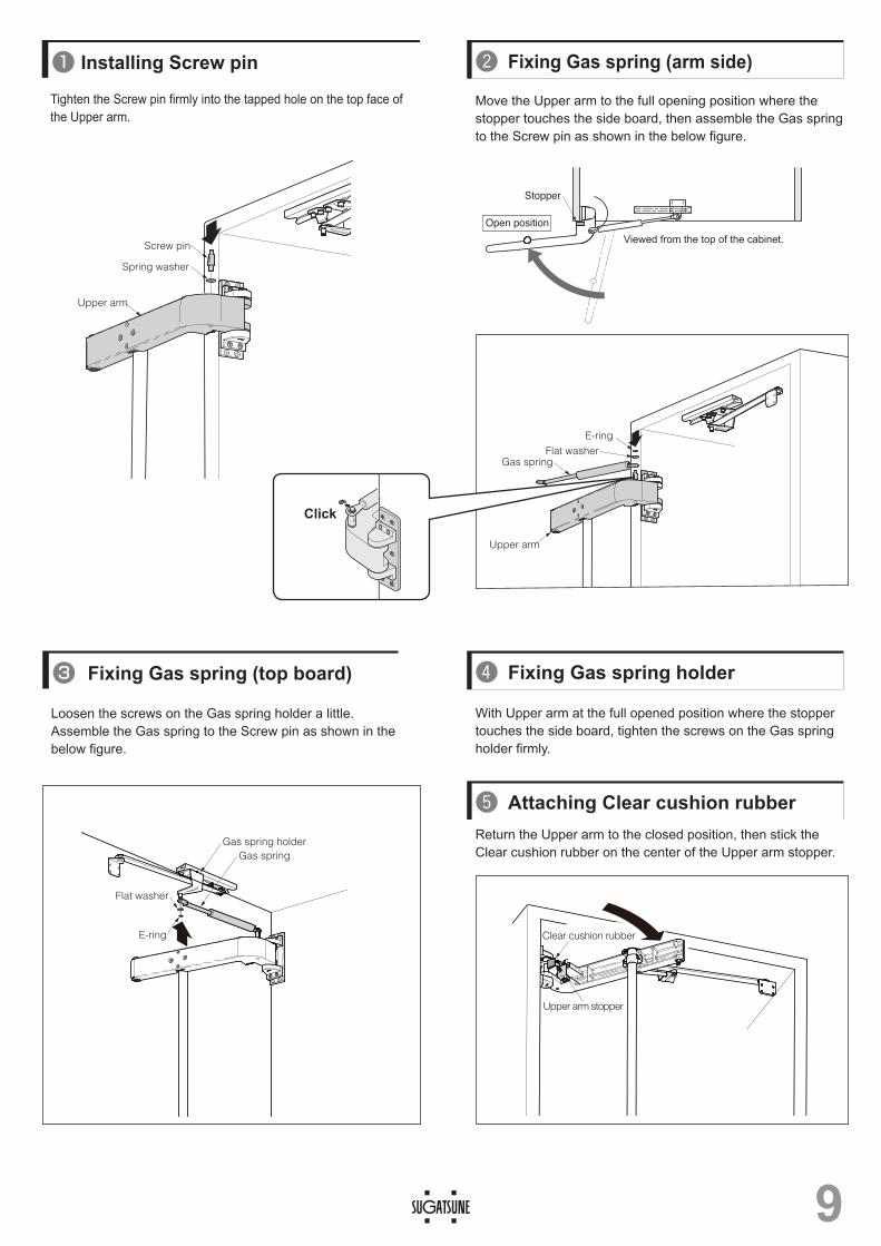
Tighten the Screw pin firmly into the tapped hole on the top face of the Upper arm.
Loosen the screws on the Gas spring holder a little. Assemble the Gas spring to the Screw pin as shown in the below figure.
1 Installing Screw pin
3 Fixing Gas spring (top board)
Stopper
Open position
Viewed from the top of the cabinet.
Spring washer
Screw pin
Upper arm
E-ring
Flat washerGas spring
Upper arm
Move the Upper arm to the full opening position where the stopper touches the side board, then assemble the Gas spring to the Screw pin as shown in the below figure.
Fixing Gas spring (arm side)
With Upper arm at the full opened position where the stopper touches the side board, tighten the screws on the Gas spring holder firmly.
Fixing Gas spring holder
Return the Upper arm to the closed position, then stick the Clear cushion rubber on the center of the Upper arm stopper.
Attaching Clear cushion rubber
Flat washer
E-ring
Gas spring holderGas spring
Upper arm stopper
Clear cushion rubber
Click

10
Do
or
en
d s
ide
Han
gin
g s
ide
Reference of aInside of cabin
Ceiling
Floor surface
Rear face of door
5 Installing parts to the door
brush seal
Rear face of door
rogo can be seen in the upright position
Positioning unitCross-recessed bind self-tapping screw 4.5 x 20
Mount the Positioning unit on the rear face of the door with the provided screws so that the LAMP logo can be seen properly.
Fixing Positioning unit
Stick the Brush seal to both edges on the rear face of the door.
Sticking Brush seal
Set core material of which strength is enough for secure tightening of self-tapping screws to the locations that parts are to be installed.Dimensions in lateral direction are determined with the (width) of the cabinet (wooden frame) regarded as the reference position. If the door end face is regarded as the reference position, add the overlaying allowance.
CAUTION

11
Upper arm
Lower
Upper
Support arm
Positioning unit
Pipe clamp
Positioning unit
Arm connecting pipe
Upper arm(w/ stopper)
Lower arm
Rear face of door
as below.The figure shows the Upper arm from underneath.
2. When hanging the door, place a support under thedoor.This is to protect the door and roughly match the height of Upper and Lower arms and Positioning units.
3. Hang the door in the following manner.(1) Tighten the horizontal positioning screws on the
Upper and Lower positioning units.
(2) Align the top surfaces of the Upper and Lower positioning units on the door with the bottom surfaces of the Upper and Lower arms.
(3) Insert a hexagon head bolt into the connecting hole with the flat washer.
(4) Screw the hexagon head bolt into the positioning unit until its leading end protrudes by about 10 mm.
(5) Screw a hexagon nut into position until it touches the positioning unit.
6 Installing door
Back face of the door viewed from the inside of the cabinet
Assembling Upper and Lower arms and Positioning unit
CautionAssemble the Upper arm and Upper positioning unit first, then assemble the Lower arm and Lower positioning unit.
Hexagon head bolt M10×150
Flat washer
Arm
Positioning unit
Hexagon nut M10
Connecting hole
Upper
Upper
Lower
Lower
10
mm
Leave a clearance here

12
1. Measure the horizontal gap between the door and cabinet.If there is any gap to be corrected, loosen the Hexagon socket head bolt on the Support arm crank bracket. (See P. 13 ④ .)
2. Loose the horizontal fixing screws on both Upper and Lower positioning units.
3. Turn the horizontal positioning screws.(1) Turn the screws clockwise to move the door to the left or
counterclockwise to move the door to the right when the door is viewed from the front.
Be sure that the side board of the cabinet is assembled in a vertical direction.
1. Remove the support and close the door gently.2. Measure the clearance between the top surface of the door
and the top board.(1) The difference between the planned dimension and the
measurement is the required amount of adjustment.(2) If there is no gap to correct, proceed to “③ Horizontal
positioning of door.”(3) Replace the support in the original position and open the
door again.・Loosen the hexagon head bolt on the Upper and Lower arms
a little.・Refer to the right figure and adjust the height. After the
adjustment, turn the hexagon bolt on the Lower arm clockwise.・Close the door gently and check the height.・
3 Horizontal positioning of door
2 Vertical positioning of door
Horizontal positioning
Horizontal positioning screws
3
2
Arm
Positioning unit
Horizontal fixing screw
Note that there should be no gap between the Hexagon bolt and washer for both Upper and Lower arms.If any gap is found, tighten the Hexagon bolts so that the load on the two arms will be equal.
Caution Clockwise360°
1.5mmUpward
Counter clockwise 360°
1.5mmDownward
Counter Clockwise
Clockwise
Support arm crank bracket
Counter Clockwise
Clockwise
Left hangingRight hanging
Hexagon head boltM10×150 ArmDoor
Vertical adjustment
Positioning unit
Tighten this hexagon nut after vertical adjustment is complete.
Gap is not allowed
Leave a clearance here
When positioning the door, be sure to loosen the hexagon socket head cap screw on the Support arm crank bracket (see P. 6 ④ ) to allow the bracket to move along the Channel rail.

13
Fix Support arm crank bracket.
Close the door completely, and fix the Support arm L-type bracket to the door with provided screws.
Fixing Support arm
Loosen the hexagon socket head cap screws on the Support arm crank bracket, and allow the bracket to move along the Channel rail.
Release Support arm crank bracket.
Loosen the screws on the Lower arm which fix the Arm connecting pipe.While keeping the door closed with no gap between the door and side board, retighten the screws.If there is any gap left, adjust it by referring to "7 Troubleshooting 【4】".
Adjusting the gap between the side board and door.
Support arm
Support arm crank bracket
Channel rail
Hexagon socket head cap screw M6×12
Cross-recessed bind self-tapping screw 4.5×20
Support arm L-type bracket
Rear face of door
When positioning the door, be sure to loosen the hexagon socket head cap screw on the Support arm crank bracket to allow the bracket to move along the Channel rail.
Be sure to face the pin of the crank bracket to the rear of the cabinet.
Arm connecting pipe
Pipe clamp
Lower arm
Hexagon socket head cap screw M6X35
Rear face of door
Tightening torque:11-13 N·m

14
Possible cause:Positioning unit may touch the arm.Solution:Refer to P. 12 ② and make a clearance between the Positioning unit and arm.
Hexagon socket headcap screw B M6×35
Hexagon socket headcap screw A M6×35
Support arm crank bracket
Hexagon socket head cap screw M6×12
Rear face of door
Door end side
Hanging side
Solution: Check the following in order.(1) Vertical positioning, (2) Horizontal positioning (P.12), (3) Positioning of Crank bracket (P.13), and (4) Door close
position adjuster screw A, B (P.15) Possible cause;
If you adjust the vertical position or horizontal position in the last order, the gap between the door and cabinet may vary.
7 Troubleshooting【1】 Large friction sound when opening/closing door
【2】 A gap remains between the side board and the door (hanging side) or it takes a long time to be closed.
(1) In case of large gap
Possible cause:The position of Crank bracket may be improper.Solution:Loosen the screws on the bracket and move the bracket to the door-end direction. Then re-tighten the screws. (See P. 12.)
(2) In case of small gap Possible cause:Horizontal positioning of door may be improper.Solution:
adjust the position by rotating the Horizontal positioning screw.
ArmHexagon head bolt M10×150
Leave a clearance here
Positioning unit
Rear face of door
Support arm crank bracket
Hexagon socket head Cap screw M6×12
Door end side Hanging side
Vertical positioning(1)
(2)
ArmConnecting hexagon head bolt
Door positioning unit
Horizontal positioning
Horizontal positioning screws
【3】 Gap between door and cabinet varies after horizontal positioning
Arm
Positioning unit
Horizontal fixing screw
Horizontal positioning
Horizontal positioning screws
Video Link

15
【4】 Gap between door and cabinet still remainsOverview:
This system controls the slant of the door by bowing the Connecting pipe. Simply try the following method unsuspectingly.
Release the stress on Connecting pipe by loosening the 4 pcs of Hexagon socket head cap screws.*Also, loosen Door close position adjuster screw A and B, so that it make a clearance between the Upper arm and the Connecting pipe.*Adjustment need to be done from inside the cabinet at the closed door.
Gap at the top
Gap at the bottomArm connecting pipe
Hexagon socket head cap screw M6X35
Pipe clamp
Lower arm
Tightening torque:11-13 N·m
Hexagon socket headcap screw B M6×35
Hexagon socket headcap screw A M6×35
Arm connecting pipe
Hexagon socket head cap screw M6X35
Tighten
Tighten afterthe adjustment
Loosen
Tighten
Tighten afterthe adjustment
Loosen
In case the gap still remains, even if the Connecting pipe is 7 or 8 mm apart from Upper arm, once loosen the Door position adjuster screw A and B completely, then tighten them until the Connecting pipe touches Upper arm. (See
Hexagon socket headcap screw A M6×35
Hexagon socket headcap screw B M6×35
Cross section C-C
C
C
Tighten the Hexagon socket head cap screws on Lower arm. Adjustment would not be achieved if the screws on Lower arm were loose.

Possible cause:
The position of the handle may be improper.
The arm may be bent or out of alignment due to improper opening
force if the handle is located far from the Hanging side.
Try the alignment.
If the parts are damaged. Contact us.
【6】 Out of alignment after using
Possible cause:Large doors are likely to warp, and perfect adjustment is not possible in case of a large warp.Adjust the gap between the door and the cabinet by attaching either the Brush seal or alternatively use "BS Bumpers" (sold separately).
2018.10 0216-6
【5】 There are gaps on all four corners
In case the door bows inward.It is not possible to make more than 2 corners to be contacted.
In case the door bows outward.It is not possible to make more than a corner to be contacted.
Brush sealFAD-44:(5000 mm)×1FAD-44L:(6000 mm)×1
BS Bumpers(sold separately)You can choose various thickness.


