Woodburning Range - Waterford Stanley · Place cement blocks or other strong supports ... Ensure...
17
Woodburning Range SAFETY NOTICE PLEASE READ THIS ENTIRE MANUAL BEFORE YOU INSTALL AND USE YOUR NEW COOK STOVE. FAILURE TO FOLLOW INSTRUCTIONS MAY RESULT IN PROPERTY DAMAGE, BODILY INJURY OR EVEN DEATH. SAVE THESE INSTRUCTIONS FOR FUTURE REFERENCE. IF THIS APPLIANCE IS NOT PROPERLY INSTALLED, A HOUSE FIRE MAY RESULT. FOR YOUR SAFE- TY, FOLLOW THE INSTALLATION DIRECTIONS. CONTACT LOCAL BUILDING OR FIRE OFFICIALS ABOUT RESTRICTIONS AND INSTALLATION INSPECTION REQUIREMENTS IN YOUR AREA. THIS APPLIANCE MUST BE CONNECTED TO A LISTED, HIGH-TEMPERATURE RESIDENTIAL TYPE AND BUILDING HEATING APPLIANCE CHIMNEY OR AN APPROVED MASONRY CHIMNEY WITH FLUE LINER. THE COMPLETE INSTALLATION MUST BE DONE IN ACCORDANCE WITH CURRENT STANDARDS AND LOCAL CODES. IT SHOULD BE NOTED THAT THE REQUIREMENTS AND THESE PUBLICATIONS MAY BE SUPERSEDED DURING THE LIFE OF THIS MANUAL. THIS APPLIANCE IS HOT WHILE IN OPERATION AND RETAINS ITS HEAT FOR A LONG PERIOD OF TIME AFTER USE. CHILDREN, AGED OR INFIRM PERSONS SHOULD BE SUPERVISED AT ALL TIMES AND SHOULD NOT BE ALLOWED TO TOUCH THE HOT WORKING SURFACES WHILE IN USE OR UNTIL THE APPLIANCE HAS THOROUGHLY COOLED. MANUFACTURED BY: WATERFORD STANLEY (MARKETING) LTD., BILBERRY, WATERFORD, IRELAND. ASSEMBLY INSTALLATION AND OPERATING INSTRUCTIONS
Transcript of Woodburning Range - Waterford Stanley · Place cement blocks or other strong supports ... Ensure...

Woodburning Range
SAFETY NOTICEPLEASE READ THIS ENTIRE MANUAL BEFORE YOU INSTALL AND USE YOUR NEW COOK STOVE.
FAILURE TO FOLLOW INSTRUCTIONS MAY RESULT IN PROPERTY DAMAGE,
BODILY INJURY OR EVEN DEATH. SAVE THESE INSTRUCTIONS FOR FUTURE REFERENCE.
IF THIS APPLIANCE IS NOT PROPERLY INSTALLED, A HOUSE FIRE MAY RESULT. FOR YOUR SAFE-
TY, FOLLOW THE INSTALLATION DIRECTIONS. CONTACT LOCAL BUILDING OR FIRE OFFICIALS
ABOUT RESTRICTIONS AND INSTALLATION INSPECTION REQUIREMENTS IN YOUR AREA.
THIS APPLIANCE MUST BE CONNECTED TO A LISTED, HIGH-TEMPERATURE RESIDENTIAL TYPE
AND BUILDING HEATING APPLIANCE CHIMNEY OR AN APPROVED MASONRY
CHIMNEY WITH FLUE LINER.
THE COMPLETE INSTALLATION MUST BE DONE IN ACCORDANCE WITH CURRENT STANDARDS ANDLOCAL CODES. IT SHOULD BE NOTED THAT THE REQUIREMENTS AND THESE PUBLICATIONS MAYBE SUPERSEDED DURING THE LIFE OF THIS MANUAL.
THIS APPLIANCE IS HOT WHILE IN OPERATION AND RETAINS ITS HEAT FOR A LONG PERIOD OF
TIME AFTER USE. CHILDREN, AGED OR INFIRM PERSONS SHOULD BE SUPERVISED AT ALL TIMES
AND SHOULD NOT BE ALLOWED TO TOUCH THE HOT WORKING SURFACES WHILE IN USE OR UNTIL
THE APPLIANCE HAS THOROUGHLY COOLED.
MANUFACTURED BY: WATERFORD STANLEY (MARKETING) LTD., BILBERRY, WATERFORD,
IRELAND.
ASSEMBLY INSTALLATION AND OPERATING INSTRUCTIONS

1
TABLE OF CONTENTS
PAGE
Assembly. . . . . . . . . . . . . . . . . . . . . . . . . . . . . . . . . . . . . . . . . . . . . . . . . . . . . . . . . . . . . 2
Installation . . . . . . . . . . . . . . . . . . . . . . . . . . . . . . . . . . . . . . . . . . . . . . . . . . . . . . . . . . . . 4
Installation Clearances to Combustibles. . . . . . . . . . . . . . . . . . . . . . . . . . . . . . . . . . . . . 4
Reduced Clearances. . . . . . . . . . . . . . . . . . . . . . . . . . . . . . . . . . . . . . . . . . . . . . . . . . . . 4
Rear Exit . . . . . . . . . . . . . . . . . . . . . . . . . . . . . . . . . . . . . . . . . . . . . . . . . . . . . . . . . . . . . 4
Floor Protection . . . . . . . . . . . . . . . . . . . . . . . . . . . . . . . . . . . . . . . . . . . . . . . . . . . . . . 5
Chimney . . . . . . . . . . . . . . . . . . . . . . . . . . . . . . . . . . . . . . . . . . . . . . . . . . . . . . . . . . . . . 5
Chimney Types USA. . . . . . . . . . . . . . . . . . . . . . . . . . . . . . . . . . . . . . . . . . . . . . . . . . . . 5
Chimney Type Canada . . . . . . . . . . . . . . . . . . . . . . . . . . . . . . . . . . . . . . . . . . . . . . . . . 5
Chimney Connector . . . . . . . . . . . . . . . . . . . . . . . . . . . . . . . . . . . . . . . . . . . . . . . . . . . . 5
Chimney Connector USA Only . . . . . . . . . . . . . . . . . . . . . . . . . . . . . . . . . . . . . . . . . . . 5
Connecting to Masonry Chimney . . . . . . . . . . . . . . . . . . . . . . . . . . . . . . . . . . . . . . . . . . 6
Thimbles . . . . . . . . . . . . . . . . . . . . . . . . . . . . . . . . . . . . . . . . . . . . . . . . . . . . . . . . . . . . . 6
Chimney Connector Systems, Thimbles & Clearances From Combustible Walls . . . . . 6
Masonry Fireplace. . . . . . . . . . . . . . . . . . . . . . . . . . . . . . . . . . . . . . . . . . . . . . . . . . . . . . 7
Ventilation & Combustion Air Requirements . . . . . . . . . . . . . . . . . . . . . . . . . . . . . . . . . . 8
Spillage Test . . . . . . . . . . . . . . . . . . . . . . . . . . . . . . . . . . . . . . . . . . . . . . . . . . . . . . . . . . 8
Maintenance . . . . . . . . . . . . . . . . . . . . . . . . . . . . . . . . . . . . . . . . . . . . . . . . . . . . . . . . . . 9
Efficient Economical Use Of Wood. . . . . . . . . . . . . . . . . . . . . . . . . . . . . . . . . . . . . . . . . 9
Creosote - Formation & Need For Removal . . . . . . . . . . . . . . . . . . . . . . . . . . . . . . . . . . 9
Disposal Of Ashes . . . . . . . . . . . . . . . . . . . . . . . . . . . . . . . . . . . . . . . . . . . . . . . . . . . . . 10
Hints On Fire Safety. . . . . . . . . . . . . . . . . . . . . . . . . . . . . . . . . . . . . . . . . . . . . . . . . . . . 10
Fuels . . . . . . . . . . . . . . . . . . . . . . . . . . . . . . . . . . . . . . . . . . . . . . . . . . . . . . . . . . . . . . . 10
Lighting The Fire . . . . . . . . . . . . . . . . . . . . . . . . . . . . . . . . . . . . . . . . . . . . . . . . . . . . . . 10
Controlling The Fire . . . . . . . . . . . . . . . . . . . . . . . . . . . . . . . . . . . . . . . . . . . . . . . . . . . . 10
The Hotplate. . . . . . . . . . . . . . . . . . . . . . . . . . . . . . . . . . . . . . . . . . . . . . . . . . . . . . . . . . 11
The Oven . . . . . . . . . . . . . . . . . . . . . . . . . . . . . . . . . . . . . . . . . . . . . . . . . . . . . . . . . . . . 11
Overnight Burning . . . . . . . . . . . . . . . . . . . . . . . . . . . . . . . . . . . . . . . . . . . . . . . . . . . . . 11
Riddling . . . . . . . . . . . . . . . . . . . . . . . . . . . . . . . . . . . . . . . . . . . . . . . . . . . . . . . . . . . . . 11
Flue Cleaning . . . . . . . . . . . . . . . . . . . . . . . . . . . . . . . . . . . . . . . . . . . . . . . . . . . . . . . . . 11
Chimney Cleaning . . . . . . . . . . . . . . . . . . . . . . . . . . . . . . . . . . . . . . . . . . . . . . . . . . . . . 11
Use Of Tools. . . . . . . . . . . . . . . . . . . . . . . . . . . . . . . . . . . . . . . . . . . . . . . . . . . . . . . . . . 11
Vitreous Enamel Cleaning . . . . . . . . . . . . . . . . . . . . . . . . . . . . . . . . . . . . . . . . . . . . . . . 11
Warming Shelf - Left or Right Hand Location . . . . . . . . . . . . . . . . . . . . . . . . . . . . . . . . 12
Assembly Instructions - Warming Oven . . . . . . . . . . . . . . . . . . . . . . . . . . . . . . . . . . . . 13
Exploded View . . . . . . . . . . . . . . . . . . . . . . . . . . . . . . . . . . . . . . . . . . . . . . . . . . . . . . . . 14
List Of Parts . . . . . . . . . . . . . . . . . . . . . . . . . . . . . . . . . . . . . . . . . . . . . . . . . . . . . . . . . . 15
Warranty. . . . . . . . . . . . . . . . . . . . . . . . . . . . . . . . . . . . . . . . . . . . . . . . . . . . . . . . . . . . . 16

1. Remove packing strip from the top of the range.
Place the sheet steel back plate to one side.
Remove all loose components from the top of
the range and firebox and the oven. Remove
the oven door. Spread the components on
the floor so you can identify them easily.
2. Place cement blocks or other strong supports
about 458mm (13”) high behind the range.
Space the supports behind it and lay the cooker
on its back.
3. Fit the four legs (Part no. 36) to the four base
corners (Part no. 13) using the hexagon-head
bolts and washers. Note that each of the front
legs (No. 36) has a screw hole in the front.
4. Lift the range off the supports. Stand it upright
without putting any strain on the legs.
5. Join the two sections of the front skirting
together (Part Nos. 37 and 38) by screwing the
name plate (Part No. 51) with its back fixing
strip (Part No. 54) into position between the two
sections and secure the two sections tightly to
the name plate.
6. Fit the complete skirting under the front of the
range inside the front legs using a screw and nut
to secure it to each leg.
7. Move the range into position for installation.
CAREFUL: Do not break a leg!
8. Ensure that the cast iron fire liners (part
nos.44,46,47,48 & 49) are secure in the
firebox at the front, sides and back.
9. Place the oven damper in position (Part No.
63) on top of the oven and place the round
hotplate (Part No. 20) in position above it.
Place the oblong hotplate (Part No. 19) and
the two round cleaning cups (Part No. 15) in
position to complete the cooker top.
10. Place the top flue outlet (Part No. 55) in
position and fit its front cleaning door (Part
no. 56) in position.
11. Screw the towel rail brackets (Part Nos. 25 and
26) to the top front of the range (Part No. 1) and
fix the towel-rail (Part No.78) in position
between the brackets. Tighten up the screws.
2
ASSEMBLY
Fig.1
Fig.2
Fig.3

12. Hang the fire door (Part No. 57) and the
ashpit door (Part No. 3) on their hinges.
13. Place the oven shelves in position (Part No.12)
the cast iron shelf below the sheet steel shelf.
14. Place the cleaning door (Part No. 59) in
position beneath the oven door (Part No. 2).
15. Screw the splashback (Part No. 67) to its two
supports (Part Nos. 61 & 62) keeping the folded
end to the bottom. Screw the plate rack (Part
No. 88) to the splashback. Screw the complete
assembly on to the cooker top (Part No. 18).
The Waterford Stanley Woodburning Range is
equipped for top flue connection. Should you wish
to vent the range to the rear the following modifica-
tions must be undertaken:
1. Remove the top flue collar (item 1) and seal
the opening with the blanking plate (item 2)
provided.
2. Remove the small panel (item 3) from the back
of the range and the blanking plate (item 4)
which will now be visible.
3. Screw the rear flue collar (item 5) provided to
the back of the range.
3
Note: Platerack and Splashback is an optional
extra, not supplied as standard.
Fig.4
Fig.5
Article 1
Article 5
Article 2
Article 4
Article 3

INSTALLATION
When installing, operating and maintaining a solid
fuel heater, respect basic standards of fire safety.
Read these instructions carefully before commenc-
ing the installation. Failure to do so may result in
damage to persons and property. Consult your local
municipal office, Fire Department and your insur-
ance representative to determine what regulations
are in force.
INSTALLATION CLEARANCES TO
COMBUSTIBLES
Front 48” 1220mm
Back 16” 400mm
Oven Side 6” 150mm
Oven Side with Optional
Shelf Fitted 10” 250mm
Firebox Side 12” 300mm
Single Wall Flue Pipe 18” 460mm
REDUCED CLEARANCES
These clearances may be reduced by the applica-
tion of protection to combustible walls and ceilings.
ULC/UL Labelled Heat Shields installed in accor-
dance with the manufacturers instructions or shields
complying with the requirements of “Installation
Code for Solid Fuel Fired Appliances CAN31336” or
“Standard for Chimneys, Fireplaces and Vents NFPA
No. 211.”
REAR EXIT
Back 6” 150mm
Oven side 6” 150mm
Firebox Side 12”300mm
4
Fig.6
Fig.7
REAR EXITFig.8
(2130mm)
(2130mm)
(300mm) (150mm)
(400mm)
(300mm) (150mm)
(150mm)
(100mm)
(150mm) clearance or less
(2130mm)
(225mm)
(200mm)
(2130mm)
(2130mm)
(460mm)
(300mm) (250mm)
(300mm)
(150mm)
(150mm)

FLOOR PROTECTION
When installing the Waterford Stanley Woodburning
Range on a combustible floor, a floor protector con-
sisting of a layer of non-combustible material at least
3/8” (9mm) thick of 1/4” (6mm) thick covered with a
1/8” (3mm) sheet of metal is required to cover the
area under the heater and to extend to at least 18”
(460mm) at the front and 8” (200mm) to the sides
and back of stove. This will provide protection from
sparks and embers which may fall out from the door
when stoking or refuelling.
CHIMNEY
The Waterford Stanley Woodburning Range must be
connected to a Factory-Built Chimney, installed in
accordance with the manufacturer’s instructions or a
lined masonry chimney, acceptable to the authority
having jurisdiction. An existing masonry chimney
should be inspected and if necessary repaired by a
competent mason or be relined using an approved
relining system.
THE CHIMNEY SERVING THE WATERFORD
STANLEY WOODBURNING RANGE SHOULD
NOT SERVE ANY OTHER APPLIANCES. If you
intend to use a fireplace chimney, the fireplace
opening must be sealed. The overall height of the
chimney, measured from the floor on which the
Range is installed must be at least 4.572 meters
(15ft). Do not use more than two elbows.
CHIMNEY TYPES USA
The Residential Type Chimney may be:
(a) FACTORY-BUILT U.L. Listed Residential Type
HT and Building Heating Appliance chimney
(ANSI/UL103) and acceptable to the local build-
ing core or,
(b) MASONRY, Constructed in accordance with
NFPA 211 code.
CHIMNEY TYPE CANADA
This Waterford Stanley Woodburning Range must
be connected to an Underwriters Laboratories of
Canada Labelled factory Built 650oC Chimney,
installed in accordance with the manufacturer’s
instructions or a lined masonry chimney acceptable
to the authority having jurisdiction.
CHIMNEY CONNECTOR
Single wall stove pipe, used to connect the appli-
ance to the chimney must be installed with the
crimped end towards the stove. This will ensure that
condensing moisture from the burning wood will flow
back into the fire chamber. Each joint in the stove
pipe must be secured with a least 3 sheet metal
screws.
Connectors should be 6” 153mm in diameter and
crimped into the fire outlet collar. Corrosion-resis-
tant steel, 24 gauge or heavier, is recommended.
(Cheap metal pipes are easily damaged by flue gas
acids).
A minimum clearance of 450mm (18”) is required for
a single wall connector.
CHIMNEY CONNECTOR USA ONLY
Connectors should maintain a pitch or rise of at least
1/4” (6mm) to the foot from this cook stove to the
chimney. It should be installed so as to avoid sharp
turns or other construction features that would cre-
ate excessive resistance to the flow of flue gasses.
It should be securely supported with joints fastened
with sheet-metal screws, rivets or other approved
means. The entire length of a connector should be
readily accessible for inspection, cleaning and
replacement.
The connector may pass through walls or partitions
constructed of combustible materials provided the
connector is either listed for wall pass-through or is
routed through a device listed for a wall pass-
through and is installed in accordance with the con-
ditions of the listing. Any unexposed metal that is
used as part of a wall pass-through system is
exposed to flue gasses shall be constructed of stain-
less or other equivalent material that will resist cor-
rosion, softening, or cracking from flue gas at tem-
peratures up to 982o C.
Where passage through a wall, or partition of com-
bustible construction is desired, the installation shall
conform to CAN/CSA - B 365, Installation Code for
Solid Fuel Burning Appliance & Equipment.
5
Fig.9
(200mm)
(200mm)(200mm)
(460mm)

CONNECTING TO MASONRY CHIMNEY
The connector to a masonry chimney must extend
through the wall to the inner face or liner but not
beyond, and must be firmly cemented to masonry.
The connector may pass through walls or partitions
constructed of combustible material to a masonry
chimney provided the connector system selected is
installed in accordance with the proper clearances
and conditions.
THIMBLES
Thimbles for chimneys or vent connectors should be
of fire clay (ASTM C 315, specifications for Clay
Flue Linings), galvanised steel of minimum
thickness of 24 gauge, or material of equivalent
durability. Thimbles should be installed without
damage to the liner. The thimble should extend
through the wall to, but not beyond, the inner face of
the liner and should be firmly cemented to masonry.
Thimbles should be located to provide adequate
pitch or rise of chimney or vent connectors and,
where the ceiling above the appliance is constructed
of combustible material, the location of the thimble
should provide minimum clearance required for the
connector as specified in section under Minimum
Clearances to Combustibles.
Insulation material used as part of wall pass-through
system should be of non-combustible material and
should have a thermal conductivity of 1.0 Btu. in./ft.F
(4.88kg.cal/hr.m.c) or less. All clearances and thick-
nesses are minimums; larger clearances and thick-
nesses are acceptable. Any material used to close
up the opening for the connector should be of non-
combustible material. A connector to a masonry
chimney, except for System 2 (under heading
Chimney Connector System, Thimbles and
Clearances), shall extend to piece through the wall
pass-through system and the chimney wall to the
inner face of the flue liner, but not beyond.
CHIMNEY CONNECTOR SYSTEMS, THIMBLES
AND CLEARANCES FROM COMBUSTIBLE
WALLS
1. Minimum 3 1/2” (90mm) thick brick masonry
wall framed into combustible wall with a min. of
12” (305mm) brick separation from clay liner to
combustibles. Fire clay liner (ASTM C315 or
equivalent) min. 5/8” (16mm) wall thickness,
should run from outer surface of brick wall to,
but not beyond, the inner surface of chimney
flue liner and should be firmly cemented in
place.
2. Solid insulated listed factory-built chimney
length of the same inside diameter as the
chimney connector and having 1” (25mm) or
more of insulation with a min. 9” (230mm) air
space between the outer wall of the chimney
length and combustibles. The inner end of the
chimney length shall be flush with the inside of
the masonry chimney flue and shall be sealed to
the flue and to the brick masonry penetration
with non water-soluble refractory cement.
Supports should be securely fastened to wall
surfaces on all sides. Fasteners between sup
ports and the chimney length shall not penetrate
the chimney liner.
6
Fig.10
Fig.11
(50mm)
(305mm)
Minimum 12” (305mm)
to combustibles
of brick
(50mm)
(230mm)
(230mm)minimum
3. Sheet steel chimney connector, min. 24 gauge
in thickness, with a ventilated thimble, min. 24
gauge in thickness, having two 1” (25mm) air
channels, separated from combustibles by a
min. of 6” (150mm) of glass fibre insulation.
Opening should be covered and thimble sup-
ported with a sheet steel support, min. 24 gauge
in thickness. Supports should be securely fas-
tened to wall surfaces on all sides and should be
sized to fit and hold chimney section. Fasteners
used to secure chimney sections should not
penetrate chimney flue liner.
4. Solid insulated listed factory-built chimney
length with an inside diameter 2” (50mm) larger
than the chimney connector and having 1”
(25mm) or more of insulation, serving as a
pass-through for a single wall sheet steel chim-
ney connector of min. 24 gauge thickness, with
a min. 2” (50mm) air space between the outer
wall of chimney section and combustibles. Min.
length of chimney section shall be 12” (305mm).
Chimney section concentric with and spaced 1”
(25mm) away from connector by means of sheet
steel support plates on both ends of chimney
section. Opening shall be covered and chim-
ney section supported on both sides with sheet
steel supports of min. 24 gauge thickness.
Supports should be securely fastened to wall sur-
faces on all sides and shall be sized to fit and hold
chimney section. Fasteners used to secure chimney
sections should not penetrate chimney flue liner.
MASONRY FIREPLACE
Before the installation the entire fireplace system
should be inspected for condition and code
compliance prior to connecting to the fireplace chim-
ney. Older fireplaces and chimneys may not have
been constructed to current-day codes.
The fireplace and chimney should be in, or brought
up to, acceptable conditions and proper clearances
should be met before connecting to the fireplace
chimney.
The size of the flue must be considered. If the
fireplace chimney is too large, a relining system may
be installed using an approved relining system.
7
Fig.12
Fig.13
Fig.14
(50mm)
(25mm)
(150mm)
glass fibre insulation
(25mm) constructed of
(50mm)
Minimum clearances 2”(50mm)
1” (50mm)
air space to
chimney
length
Air space 2” (50mm)

Connection to a masonry chimney may be done by
breaching into the chimney from the front of the fire-
place, no less than 8” (200mm) above the bottom of
the first flue tile, by installing a stainless steel or
other listed chimney connector from the appliances
flue outlet up through the fireplace damper and
smoke chamber, terminating at the first flue tile, or
by installing a stainless steel or other listed relining
system from the flue outlet up the entire length of the
chimney, where necessary.
VENTILATION & COMBUSTION AIR
REQUIREMENTS
Provision for outside combustion air may be neces-
sary to ensure that fuel-burning appliances do not
discharge products of combustion into the house.
Guidelines to determine the need for additional com-
bustion air may not be adequate for every situation.
If in doubt, it is advisable to provide additional air.
Outside combustion air may be required if:
1. The solid-fuel-fired appliance does not draw
steadily, smoke rollout occurs, fuels burns
poorly, or back drafts occur whether or not
there is combustion present.
2. Existing fuel-fired equipment in the house, such
as fireplaces or other heating appliances, smell,
do not operate properly, suffer smoke roll-out
when opened, or back-draft whether or not there
is combustion present.
3. Opening a window slightly on a calm (windless)
day alleviates any of the above symptoms.
8
Fig.15 4. The house is equipped with a well-sealed
vapour barrier and tight fitting windows and/or
has any powered devices that exhaust house
air.
5. There is excessive condensation on windows in
the winter.
6. A ventilation system is installed in the house.
If these or other indications suggest that infiltration
air is inadequate, additional combustion air should
be provided from the outdoors. Outside combustion
air can be provided to the appliance by the following
means:
1. Indirect method: for an appliance not certified
for direct connection of outside combustion air,
the outside air is ducted to a point no closer than
(12”) 300mm from the appliance, to void affect
ing the performance of the appliance.
2. A mechanical ventilation system: if the
house has a ventilation system (air change
or heat recovery):
a. The ventilation system may be able to pro-
vide sufficient combustion make-up air for
the solid-fuel-fired appliance.
b. The householder should be informed that
the ventilation system might need to be
re-balanced by a ventilation technician
after installation of the appliance.
SPILLAGE TEST
In all installations a spillage test should be carried
out to ensure there is sufficient combustion air and
the flue system is:
1. Light/burn appliance under normal conditions in
accordance with this installation manual.
2. Close all doors and windows.
3. Operate all appliances requiring air at full rate
(eg. extraction hoods, tumble dryers etc).
4. Check for spillage.

MAINTENANCE
WARNING: DO NOT CLEAN STOVE WHEN HOT.
To ensure that the Waterford Stanley Woodburning
Range will operate safely and with maximum effi-
ciency, the entire installation must be properly main-
tained. During periods of use, the range, chimney
connectors, joints and the main flue itself must be
kept clean and in good working condition. You can
clean the connectors manually. Use an approved
chimney cleaner to clear creosote deposit and
repeat as often as necessary. If you use only sea-
soned hardwoods, then only occasional chimney
cleaning will be necessary.
During the off-season the range may be stored in a
dry, covered area, but before storing it, remove the
ashes and thoroughly clean out the fire chamber
and oven flues. Touch up the black Senotherm fin-
ish as required with similar heat-resistant finish. If
such are not readily available apply a suitable oil to
prevent rust spots, so your Stanley will stay in good
condition until you need it again.
EFFICIENT ECONOMICAL USE OF WOOD
Wood combustion occurs in three stages. First the
moisture is evaporated (converted to steam), then
the volatiles are distilled and finally the fixed carbon
(charcoal) is burned. All stages of combustion can
occur at the same time, such as when fresh fuel is
added to the glowing embers.
Moisture must be evaporated and dispersed before
wood will burn. Consequently, wood should be cut
and dried for a period of several months (preferably
a year) before it is used. The moisture content of
some trees may be as high as 100%, i.e. equal in
volume to the wood itself. After dry storage over six
to ten months the moisture content will usually range
from 15% to 25%. Splitting the wood prior to storage
reduces drying time and this results in more even
burning. It minimises condensation of the water
vapour and volatile distillates, that in turn creates
creosote deposits in chimney flues.
It is apparent that greater efficiency and safety will
ensure from burning moderate quantities of dry
wood in a hot fire than using green or wet wood that
only smoulders.
The Waterford Stanley Woodburning Range ensures
that air enters the fire chamber over and around the
sides of the fire. This assures complete combustion
which in turn minimises heat losses up the flue and
reduces the amount of unburned gasses and distil-
lates to the flue. If you have no
alternative but to use soft wood, like elder, spruce or
pine, or when green wood has to be used, then the
result will be low heat and the formation of much cre-
osote. In these conditions the fire must receive
plenty of draught which will help to prevent creosote
forming. The Waterford Stanley Woodburning
Range is sealed to prevent air leaks at the joints,
consequently, wood will burn evenly by day and
overnight, because of the control you can exercise
over the rate of burning.
Cut your wood to size: 406mm (16”) logs, which will
fit the Waterford Stanley Woodburning Range fire
chamber. The longer the logs the better and more
enduring the fire will be.
Hardwoods are best for heat. These include: Beech,
Cherry, Ash, Oak, Hickory, Hard (Sugar) Maple,
Birch, Larch (Tamarack) and Elm. Elm is hard to
split but is fine for a slow burning fire, and like all
other woods, it is all the better for seasoning. Your
hardwood ashes will benefit the garden; they contain
valuable minerals including carbon, potash, phos-
phorus, copper, manganese etc. reference to the
characteristics of wood are quoted from NFPA No.
H8- I, 1974 (U.S.A).
CREOSOTE- Formation and Need for Removal
When wood is burned slowly, it produces tar and
other organic vapours, which combine with expelled
moisture to form creosote. The creosote vapours
condense in the relatively cool chimney flue of a
slow-burning fire. As a result, creosote residue
accumulates on the flue lining. When ignited this
creosote makes an extremely hot fire. We suggest
the chimney connector and chimney should be
inspected at least twice monthly during the heating
season to determine if a creosote build-up has
occurred. If creosote has accumulated it should be
removed to reduce the risk of a chimney fire.
Inspect the chimney connector frequently. Tap the
connector with your finger when the pipe is cool. If
you hear a dull echo, the pipe may need cleaning.
Disassemble the chimney connector and clean the
sections. Replace corroded pipe sections. The
fitting of a slip-joint in the stove pipe makes the
dismantling easy for cleaning and inspection of
chimney and stove.
When inspecting a masonry chimney, start at the
clean-out door, normally found in the basement, at
the base of the chimney, or on the outside. If your
chimney does not have a clean-out door it must be
inspected and cleaned by removing stove from
chimney.
9
DISPOSAL OF ASHES
Ashes should be placed in a metal container with a
tight-fitting lid. The closed container of ashes should
be placed on a non-combustible floor or on the
ground well away from all combustible materials
pending final disposal. If the ashes are disposed of
by burial in soil or otherwise locally dispersed they
should be retained in the closed container until all
cinders have thoroughly cooled.
HINTS ON FIRE SAFETY
To provide reasonable fire safety the following
should be given serious consideration:
1. The installation of smoke detectors.
2. A conveniently located Class A fire extinguisher.
3. A practical evacuation plan.
4. A plan to deal with chimney fire as follows:
(a) Notify the fire department
(b) Prepare occupants for immediate
evacuation.
(c) Close all openings into the stove
(d) While awaiting fire department,
watch for ignition of adjacent com
bustibles from overheated stove pipe
or hot embers or sparks from the
chimney.
NOTE: Inspect the chimney flue weekly until a safe
frequency is established.
FUELS
Wood logs up to 406 mm (16”).
LIGHTING THE FIRE
Open the fire door (Part no. 57), lay a few crumpled
sheets of paper on the bottom grate (Part no. 41)
then a few small dry pieces of sticks or kindling.
Open the spin wheel (Part no. 58) fully by rotating it
in an anti-clockwise direction. Turn the direct
damper (Part no. 63) to open by using the operating
tool. Now light the paper, close the fire door (Part
no. 57) when the kindling has caught fire (allow 15
minutes for this to happen) add larger pieces of dry
wood, until the fire box is half filled. When the larg-
er pieces of wood have caught fire, add full sized
logs.
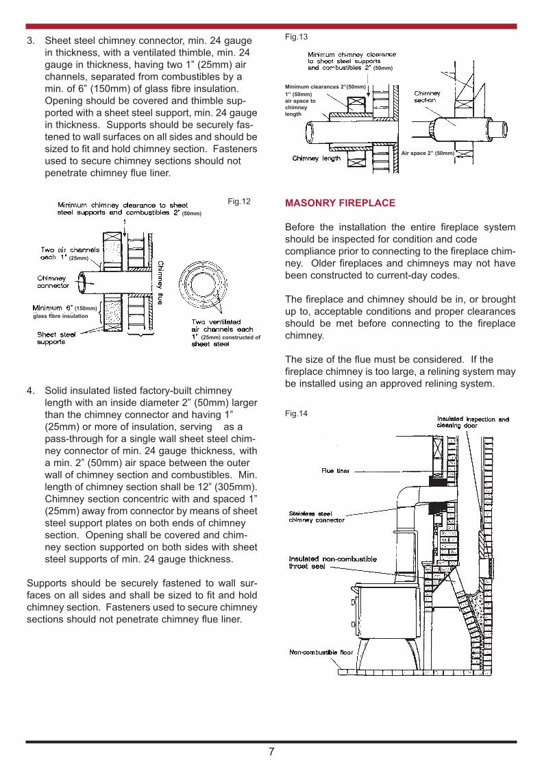
IMPORTANT: UNDER NO CIRCUMSTANCES
SHOULD ANY FLAMMABLE LIQUID, GASOLINE
KEROSENE, LIGHTER FLUID OR CHARCOAL-
STARTERS BE USED TO LIGHT OR “FRESHEN
UP” THE FIRE. NEVER USE MANUFACTURED
LOGS. OPERATE APPLIANCE ONLY WITH
FUELLING DOOR AND ASHPIT DOOR CLOSED.
“KEEP ALL SUCH LIQUIDS WELL AWAY FROM
STOVE WHILE IN USE”
OPERATE APPLIANCE ONLY WITH FUELLING
DOOR AND ASHPIT DOOR CLOSED.
CONTROLLING THE FIRE
The chimney damper must be kept closed except
when lighting the fire. Combustion is governed by
using the spin-wheel (Part No. 58) which controls
both primary and secondary air supply to the firebox.
The oven damper (Part No. 63) under the round hot-
plate (Part No. 20) reduces the chimney draught.
You will get to know how to use the spin-wheel (Part
No. 58) and the oven damper (Part No. 63) in con-
junction for the best results. Remember NOT to try
to get a quick temperature increase by opening the
chimney damper. Keep the ashpit door (Part No. 3)
closed securely except when de-ashing the fire.
Keep the firedoor (Part No. 57) closed securely
except when fuelling from the front. Loading fre-
quency of the fuel depends on burn rate. Once they
are well alight, logs need little draught to maintain
combustion.
KEEP ALL COMBUSTIBLE MATERIALS AT
LEAST 1220mm (4 feet) AWAY FROM THE
RANGE.
They include rugs, fabrics, furnishings, papers, fire-
wood, etc. NEVER dry clothing on or within 1220mm
(4 feet) of the range.
10
Fig. 16

THE HOTPLATE
Use the hotplate and the cooking-top of the range
for boiling simmering, frying, grilling, braising, etc.
Best results can be obtained by using flat bottomed
utensils. The lacquer which was applied to protect
the surface-ground hotplates will burn off. Keep the
hotplates clean with a wire brush. Over a short peri-
od you will quickly adapt to the best ways and
means of using the cooker-top in order to obtain
utmost satisfaction and efficiency.
THE OVEN
When the oven is required for baking, roasting, or
casseroling, open the oven dampers (Part No. 63)
and the spin-wheel (Part No. 58) until the oven
thermometer (Part No. 74) shows a temperature of
about 25 C below that required. Then adjust the
oven damper (Part No. 63) to reach the required
temperature without exceeding it. A little practice
will soon show how much adjustment is necessary.
OVERNIGHT BURNING
The correct setting for the spin-wheel (Part No. 58)
and the oven damper (Part No. 63) for overnight
burning can be found by experimenting. The
following routine should give the requirement. (If it
does not, the spin-wheel or the damper can be
closed more for another attempt). Open the spin-
wheel (Part No. 58) a quarter of a turn and close the
oven damper (Part No. 63) to one quarter of its max-
imum opening. Lightly riddle the fire bottom bar and
re-fuel with logs until the firebox is full. In the morn-
ing open the spin-wheel (Part No. 58) and oven
damper (Part No. 63). Lightly riddle the fire. When
the fire is burning well, top up with logs.
RIDDLING
Open the ashpit door (Part No. 3). Use the
operating tool (Part No. 30) to lightly move the
bottom grate (Part No. 41) to and fro. Empty the ash
pan (Part No. 70) as required. Always close the ash-
pit door tightly.
FLUE CLEANING
Open the oblong hot plate (Part No. 19). Remove
the simmering/oven hob cleaning cups (Part No.
15), open the direct damper (Part No. 14). Brush
deposits on the oven top into the fire box, brush
downwards the deposits in the space both behind
and at the side of the oven. Remove the cleaning
door (Part No. 59) from below the oven door (Part
No. 2). Rake the deposits through from underneath
the oven towards the front and out through the
cleaning aperture in the cooker front (Part No. 1) into
a container.
CHIMNEY CLEANING
Inspect the chimney connector frequently. Tap the
connector with your finger when the pipe is cool. If
you hear a dull echo, the pipe may need cleaning.
Disassemble the chimney connector and clean the
sections. Replace corroded pipe sections, the
fitting of a slip-joint in the stove pipe makes the
dismantling easy for cleaning and inspection of
chimney and stove.
When inspecting a masonry chimney, start at the
clean-out door, normally found in the basement, at
the base of the chimney, or on the outside. If the
chimney does not have a clean-out door it must be
inspected and cleaned by removing the stove from
the chimney.
USE OF TOOLS
11
Fig. 17
VITREOUS ENAMEL CLEANING
General cleaning must be carried out when the
stove is cool.
If this stove is finished in a high gloss vitreous enam-
el, to keep the enamel in the best condition observe
the following tips:
1. Wipe over daily with a soapy damp cloth,
followed by a polish with a clean dry duster.
2. For stubborn deposits a soap impregnated
pad can be carefully used on the vitreous
enamel.
3. DO NOT USE ABRASIVE PADS OR OVEN
CLEANSERS CONTAINING CITRIC ACID
ON ENAMELLED SURFACES. ENSURE
THAT THE CLEANSER MANUFACTUR
ERS INSTRUCTIONS ARE ADHERED TO.
Cup Lifter

WARMING SHELF - LEFT OR RIGHT HAND LOCATIONASSEMBLY INSTRUCTIONS
1. Remove the 1/4” (6mm) x 1/4” (6mm) round
head screws (2 off) from the hob and 1/4”
(6mm) x 1/4” (6mm) round head screw (1 off)
from the front and dispose of (used for packing
purposes only).
2. Bolt the bracket (2) to the Warming Shelf (1)
using the 1 1/2” (38mm) x 1/4” (6mm) csk screw
(6) and the 1” (25mm) x 1/4” (6mm) hex head
bolt (9) and 3/8” washers (10 provided.
3. Place the Warming Shelf beside the hob (3)
keeping the top face flush with the hob top
and in line with the front of the hob.
4. Attach Warming Shelf to hob with 1/2” (12mm) x1/4” (6mm)hex head bolts (8) provided and fit 1”
(25mm) x 1/4” (6mm) round head screw (7) to
front.
5. Tighten all screws.
12
Fig. 18
CONTENTS
1. Warming Shelf (1 off).
2. Bracket to Shelf (1 off).
3. Hob of Stove.
4. Front of Stove.
5. Side of Stove.
6. 1 1/2” (38mm) x 1/4” (6mm) csk chrome
plated (1 off).
7. 1” (25mm) x 1/4” (6mm) R.H. chrome plated
(1 off).
8. 1/2” (12mm) x 1/4” (6mm) hex head bolts (2 off).
9. 1” (25mm) x 1/4” (6mm) hex head bolts (1 off).
10. 3/8” (9mm) Washers (2 off).

13
ASSEMBLY INSTRUCTIONS - WARMING OVEN
1. Your warming oven is supplied in a part
assembled condition.
2. The oven is complete and the splashback,
top rail, top rail brackets and side brackets
are separate components complete with 4
No. short (M5 x 12) set screws and 4 No.
long (M5 x 20) set screws all with washers.
3. To assemble on a WOODSTANLEY already
installed with a top flue outlet proceed as
follows:
(a) Remove the inside top bolts of the warming
oven and fit the top rail between the brackets.
Place the brackets on top of the warming oven
and replace the bolts.
(b) Dismantle, clean and remove flue pipe.
(c) Remove the four screws from the hob and
place the side brackets, with the flat sur faces
outwards, on the hob. Replace the screws but
do not tighten them.
(d) Slide flue through warming oven and loosely fit
warming oven to brackets using long set
screws (M5 x 20). Reassemble flue.
(e) Remove the two small set screws (M5 x 12)
from both sides of back of warming oven and fit
splash back using the extra set screws (M5 x
12) to bolt splash back to side brackets.
(f) TIGHTEN ALL BOLTS. Your warming oven
is now ready for use.
Fig. 19 Fig. 20
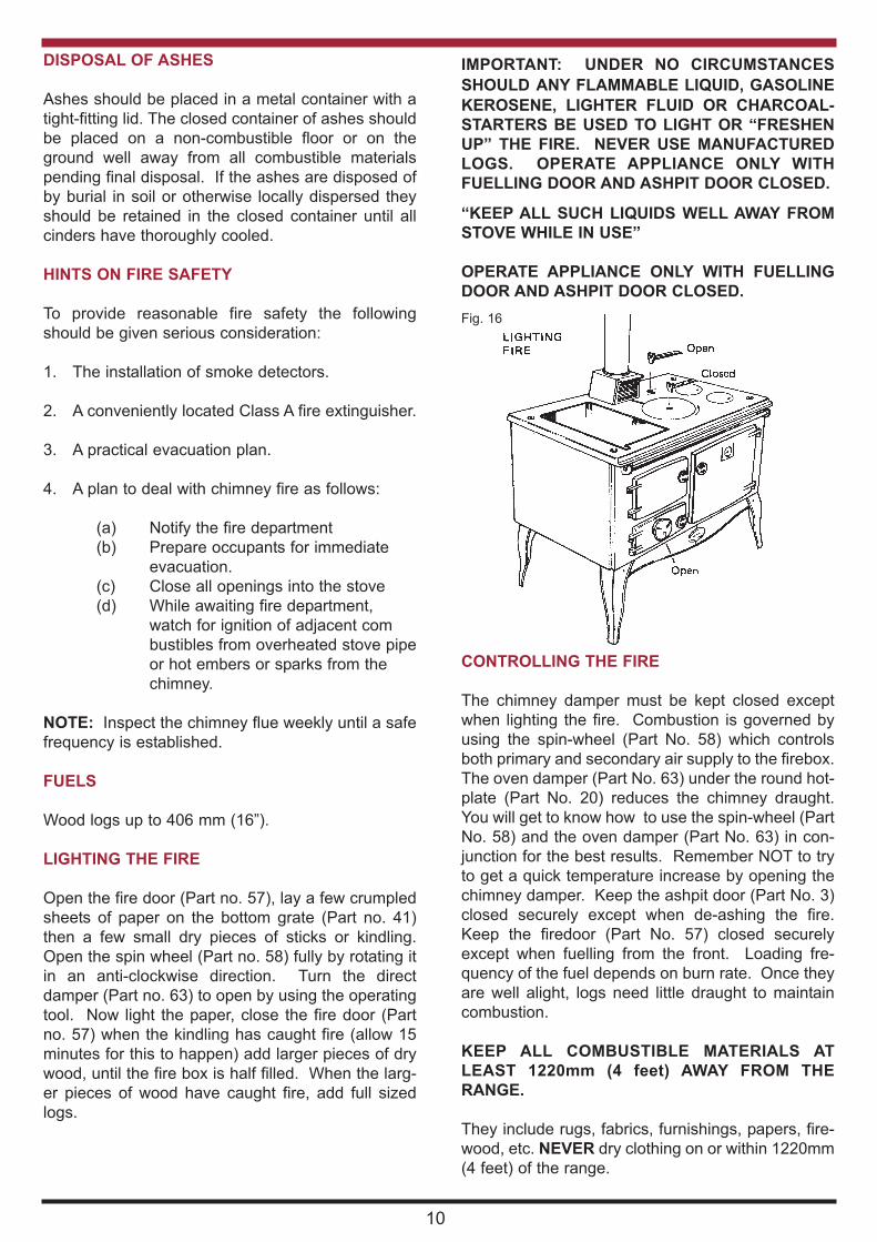
EXPLODED VIEW
14

EXPLODED VIEW PARTS LIST
No. ITEM DESCRIPTION PART CODE
1 BONNET B00124AXX
2 BONNET DOOR B00125AXX
3 SPIN VALVE B00128AXX
4 HOB SEALING PLATE B00135BXX
5 FRONT CLEANING DOOR B00141AXX
6 TOWEL RAIL BRACKET - RH B00142AXX
7 TOWEL RAIL BRACKET - LH B00143AXX
8 LEG B00144AXX
9 PLINTH RH B00145AXX
10 PLINTH LH B00146AXX
11 BONNET RING B00147AXX
12 OVEN DOOR B00148BXX
13 FIRE DOOR B00149BXX
14 ASH DOOR B00150BXX
15 FRONT B00152DXX
16 NAMEPLATE B00156AXX
17 HOB MACHINED B00292FXX
18 DOOR KNOB (LIGHT) B00383AXX
19 SMALL BACK PANEL F00056CXX
20 ASHPAN F00058AXX
21 OVEN SHELF F00061AXX
22 RIDDLING HANDLE F00063AXX
23 BASE PANEL F00071AXX
24 FIRE BAR LINK F00097AXX
25 OVEN DOOR PANEL F00139AXX
26 INNER SIDE RH/LH F00294AXX
27 OUTER SIDE PANEL RH/LH F00295AXX
28 INNER BACK PANEL F00301AXX
29 OUTER BACK PANEL F00302AXX
30 OUTER BLANKING PLATE F00304AXX
31 WS PLUG F00506AXX
32 6MM WIRE TOOL HOLDER F01182AXX
33 THERMOMETER 100-300 G00029AXX
34 SIDE INSULATION 460 X 420MM J00187AXX
35 BACK INSULATION J00220AXX
36 SERIAL NUMBER PLATE N00234BXX
37 SPIGOT Q00097AXX
38 FLUE OUTLET CONNECTION PIPE Q00098AXX
39 BOTTOM GRATE FRAME Q00114AXX
40 ASHPIT BACK Q00115BXX
41 ASHPIT SIDE RH Q00116AXX
42 ASHPIT SIDE LH Q00117AXX
43 FLUE BACK Q00119AXX
44 PLATE SEAL BACK Q00120AXX
45 OVEN BOTTOM Q00121BXX
46 OVEN SIDE RH Q00122BXX
No. ITEM DESCRIPTION PART CODE
47 OVEN SIDE LH Q00125BXX
48 OVEN BACK Q00128CXX
49 FLUE CHECK Q00129AXX
50 CLEANING DOOR CLIP Q00133AXX
51 PLINTH JOINT CLIP Q00134AXX
52 FIRE DOOR LINING Q00135AXX
53 HOT RING Q00136BXX
54 HOTPLATE CUP Q00137AXX
55 OVEN FLUE DAMPER Q00139AXX
56 HOB PROTECTING PLATE Q00140AXX
57 DAMPER WITH CUT Q00142AXX
58 BASE Q00146CXX
59 FIRE BAR STANDARD Q00148AXX
60 FIRE BAR FRAME Q00234AXX
61 BACK PANEL Q00182AXX
62 SHAM CHEEK TOP Q00183AXX
63 FALL BAR Q00229AXX
64 FALL BAR FRAME FRONT Q00230AXX
65 FALL BAR FRAME BACK Q00231AXX
66 OVEN TOP Q00235EXX
67 FIRE LINING LH Q00360AXX
68 FIRE LINING RH Q00361AXX
69 FIRE LINING TOP FRONT Q00362AXX
70 FIRE LINING BACK Q00363AXX
71 FIRE LINING BOTTOM FRONT Q00364AXX
72 HOT PLATE SOLID Q00543AXX
73 OVEN SIDE PROTECTION PLATE Q00555AXX
74 ASHPIT BOTTOM Q00595AXX
75 HOB PROTECTION PLATE Q00620AXX
76 OVEN END FLUE Q00723BXX
77 OVEN SHELF Q00728AXX
78 DOOR HANDLE (LONG) U00005AXX
79 HINGE PIN (CAM ACTION) U00030BXX
80 DOOR OPERATING TOOL U00063AXX
81 SPACER TO DOOR HANDLE V00035AXX
82 CLEANING BRUSH V00072AXX
83 POKER V00073AXX
84 SCRAPER V00074AXX
85 TOWEL RAIL V00077AXX
86 STAY ROD V00082DXX
87 DOOR LATCH V00084BXX
88 HOTPLATE LIFTER V00086AXX
89 SHAFT DOOR KNOB V00326AXX
90 STEAM VENT W00904AXX
91 STAY ROD NUT W00920AXX
92 STAY ROD NUT CAP W00923AXX
93 COMERAGH FIREBAR *** Z00026BXX
15
*** For USA Market Only

DP 140219 N00221AXX
Manufactured by
Waterford Stanley Ltd.,
Unit 401-403, IDA Industrial Estate, Cork Road,
Waterford, Ireland.
Tel: (051) 302300 Fax (051) 302315
Website: www.waterfordstanley.com
16
WARRANTY
CONDITIONS OF WARRANTY
Your Stanley cooker is guaranteed against any part that fails (under normal operating conditions) from the
date of installation of the appliance. If the unit is not installed within six months of date of purchase, the war-
ranty will commence six months from the date of purchase. The warranty is given only to the original con-
sumer/purchaser only and is non-transferable. The appliance must be installed by a suitable qualified person
and installed as per the requirements of this manual. Failure to comply with the installation requirements will
void your warranty. Waterford Stanley reserve the right to replace any part due to manufacturing defect that
fails within the warranty period under the terms of the warranty. All Oil & Gas appliances must be commis-
sioned by an authorised Stanley Engineer to validate your warranty. The unit must be used for normal domes-
tic purposes only and in accordance with manufacturer's operation instructions.
LIMITS OF LIABILITY
The warranty does not cover:
* Special, incidental or consequential damages, injury to persons or Property, or any other consequential
loss.
* Any issue with caused by negligence, misuse, abuse or circumstances beyond Waterford Stanley’s
control.
* Any issue with wear and tear, modification, alteration, or servicing by anyone other than an authorised
service engineer.
* Installation and operational related problems such as draught related issues external to the cooker,
inadequate venting or ventilation, excessive flue offsets, negative air pressure caused by insufficient
burning of improper fuel.
* Damage caused to the unit while in transit.
* Enamel discolouration due to over firing, enamel damage caused by impact, damage to baffles caused
by over firing and fading of surface finish on casting.
* Stress fractures on bricks.
* Rust on cast iron parts unless reported prior to unit being installed.
Note: Adequate clearance must be maintained around the appliance to ensure the ease of part removal in
the possible event of their damage/failure. Waterford Stanley are not responsible for any costs
incurred in the removal of items installed in the vicinity of the appliance that have to be moved to
facilitate a part replacement.
All warranty claims must be reported to the Waterford Stanley Service Department and must be submitted
with the product serial number (located on the front casting), date of purchase, proof of purchase (if request-
ed) and details of the specific nature of the problem.