
Wonderware PAC User Guide - sbprocess.fr · Troubleshooting InTouch Data Communications ......
165
HA030834/6 June 2015 (Issue 6) Wonderware PAC User Guide
Transcript of Wonderware PAC User Guide - sbprocess.fr · Troubleshooting InTouch Data Communications ......

HA030834/6
June 2015 (Issue 6)
Wonderware PACUser Guide

© 2015All rights are strictly reserved. No part of this document may be reproduced, modified, or transmitted in any form by any means, nor may it be stored in a retrieval system other than for the purpose to act as an aid in operating the equipment to which the document relates, without prior written permission of the manufacturer.
The manufacturer pursues a policy of continuous development and product improvement. The specifications in this document may therefore be changed without notice. The information in this document is given in good faith, but is intended for guidance only. The manufacturer will not accept responsibility for any losses arising from errors in this document.

3
Wonderware PAC User’s Guide
Contents
Preface ...................................................... 7Revision Information ........................................................................ 7Documentation Conventions ............................................................ 7Acronyms ........................................................................................... 8Reference Documents ....................................................................... 8Technical Support ............................................................................. 9
Chapter 1 Introduction to Wonderware PAC.................. 11Overview .......................................................................................... 11
System Architecture .................................................................... 14Supported Devices ....................................................................... 16
System Limits ................................................................................. 17Changes to The IDE Interface ........................................................ 17
Menu and Toolbar options ........................................................... 18Wonderware PAC Object Templates ........................................... 20PAC Strategies Tab ..................................................................... 22LIN Data Browser ........................................................................ 24PAC Binding Tool ........................................................................ 24LIN Connection Setup Tool ......................................................... 25Configure UStoreForward Tool ................................................... 25Using Managed Applications (EurothermSuite Project Link) .. 26
Wonderware PAC Workflow ........................................................... 29
Chapter 2 Wonderware PAC Basics.............................. 33Overview .......................................................................................... 34Stage 1: Creating A PAC Instrument Configuration .................... 34
Editing the Strategy for a Foxboro PAC Instrument ................. 40Changing the Instrument Version .......................................... 42
Using the LIN Connection Setup Tool ........................................ 44

4 Contents
Wonderware PAC User’s Guide
Downloading Strategies to a PAC Instrument ........................... 46Stage 2: Creating the Execution Platform for the PAC DAServer ....
47Stage 3: Creating a DINetwork (LIN Network Object) ................ 48Stage 4: Adding DIDevices (Instruments) to the DINetwork ....... 51
Working with Redundancy .......................................................... 54Stage 5: Binding LIN Data to ArchestrA Application Objects ..... 55
Manually Binding Objects ........................................................... 56Using the LIN Data Browser to Bind Objects ............................ 58Using the PAC Binding Tool ....................................................... 64
Block Binding tab ..................................................................... 66Field Binding tab ..................................................................... 70
Post–Configuration Procedure ....................................................... 71Using Store and Forward ............................................................ 72
Improving Productivity with the PAC Binding Tool ..................... 72
Chapter 3 Instrument Diagnostics............................... 75Overview .......................................................................................... 75Operator Interface .......................................................................... 76
Overview Display ......................................................................... 77Example Overview Display – No Faults ................................. 78Example Overview Display – Faulty Modules ....................... 79Example Overview Display – Communications Fault ........... 80Example Overview Display – Multiple Instruments ............. 81
Detailed Display ........................................................................... 82Configuration .................................................................................. 85Working with Redundancy ............................................................. 88Symbol Parameters and PAC Device Field references ................. 88
Appendix A Licensing.................................................. 93Overview .......................................................................................... 93
Appendix B Advanced Binding Tool Operation ................ 97Overview .......................................................................................... 97Exporting Binding Configuration .................................................. 98Manipulating Binding Configuration ............................................ 99
Adding a Binding Entry ............................................................ 100Using the PAC Binding Tool to Create Instances Without
Binding ................................................................................... 101Importing Binding Configuration ................................................ 101Validation ...................................................................................... 103
Appendix C Configuring Store and Forward...................105

Contents5
Wonderware PAC User’s Guide
Overview ........................................................................................ 105Using the Configure UStoreForward tool .................................... 107
Preparing the tool to run ........................................................... 108Analysing the results ................................................................. 109
Appendix D Importing Existing LIN Strategies to The Galaxy111
Overview ........................................................................................ 111Importing Existing Strategies Into The Galaxy .......................... 112
Appendix E Troubleshooting Communication Errors........115Troubleshooting Procedures ......................................................... 115
Troubleshooting at Strategy Download Time ........................... 116Troubleshooting Deployed Devices ........................................... 116Troubleshooting Write Failures ................................................ 118Troubleshooting InTouch Data Communications .................... 119
Troubleshooting Tools ................................................................... 119Network Explorer ...................................................................... 121Network UNH ............................................................................ 122Ping ............................................................................................. 123Windows Networking Configuration ........................................ 123Object Viewer ............................................................................. 124LINTools ..................................................................................... 124Shutdown LINOPC Utility ........................................................ 125System Management Console ................................................... 125
Wonderware Logger ............................................................... 128Windows Event Viewer .............................................................. 128IDE Object Configurator ........................................................... 129Windows / Third–Party Firewall ............................................... 130LIN Ports Editor Control Panel ................................................ 130ArchestrA Security Editor ......................................................... 132Windows Regional Settings ....................................................... 132Foxboro PAC Diagnostic Symbol ............................................... 133
Namespace Updates ..................................................................... 133
Appendix F Using LINtools in a Wonderware PAC Context ....135
Overview ........................................................................................ 135Disabled Commands ..................................................................... 135Wonderware PAC User–Interface Changes ................................ 136
Instrument Name ...................................................................... 136Read-only Configurations .......................................................... 136
General User–Interface Changes ................................................. 137

6 Contents
Wonderware PAC User’s Guide
Instrument Properties ............................................................... 137Instrument Options ................................................................... 137
Workflow Changes ........................................................................ 138Changing the Instrument Version or Type .............................. 138
Appendix G Enabling Cross-Subnet Communication .......139Overview ........................................................................................ 140Configuration ................................................................................ 140
Instrument Configuration ......................................................... 141Engineering Workstation Configuration .................................. 142Deployed DINetwork Configuration ......................................... 143
Appendix H Windows Firewall Configuration..................145
Glossary .................................................151
Index .....................................................161
7
Preface
This guide provides an introduction to Wonderware® PAC. It provides details on the changes to the ArchestrA® platform allowing PAC instruments to be configured and maintained. Guided walk-through examples help to explain the key concepts.
You can view this document online or you can print it, in part or whole, by using the print feature in Adobe Acrobat Reader.
This guide assumes you know how to use Microsoft Windows®, including navigating menus, moving from application to application, and moving objects on the screen. If you need help with these tasks, see the Microsoft Help.
In some areas of the product, you can also right-click to open a menu. The items listed on this menu change, depending on where you are in the product. All items listed on this menu are available as items on the main menus.
Revision InformationThis is the fifth release of this document, which adds information on how to configure the Windows 7 Firewall to allow successful EuroPRP communications.
Documentation ConventionsThis documentation uses the following conventions:
Convention Used for
Initial Capitals Paths and file names.
Bold Menus, commands, dialog box names, and dialog box options.
Monospace Code samples and display text.
Wonderware PAC User’s Guide

8
AcronymsThe following table elaborates on the acronyms used in this document:
Reference DocumentsThe Wonderware PAC system is based on the ArchestrA System Platform and incorporates several Wonderware products. All of the documentation written by Wonderware is relevant, and installed during the System Platform installation. In addition to the base System Platform documentation, there are documents that describe Wonderware PAC-specific features.
System Platform documentation can be viewed by clicking the start > Programs > Wonderware > Books menu. Additional help can also be found within the IDE in the help menu by clicking help topics or pressing F1.
Acronym Description
csv Comma Separated Value
ELIN Ethernet Local Instrument Network; the LIN protocol running over Ethernet.
FQN Fully Qualified Name to uniquely identify a LIN block field in a specific instrument, on a specific network.
IDE Integrated Development Environment – the main configuration tool in the Foxboro PAC platform
LIN Local Instrument Network that sits underneath a PAC Control System. LIN instruments comprise of Foxboro PAC instruments, and/or generic legacy LIN instruments. LIN instruments are programmable and execute a strategy that is downloaded into the instrument. A strategy consists of, amongst other items, small blocks of functionality which are virtually wired together to form a control strategy.
PAC Programmable Automation Controller. Used to refer to the control modules themselves, or as a generic name for a complete system including controllers, IO modules and associated software.
SMC System Management Console
UDA User-Defined Attribute. Provides the ability to add functionality to an object.
Wonderware PAC User’s Guide

Technical Support9
Documentation specific to Wonderware PAC can be found in the Start menu located at Program Files > Invensys > Foxboro PAC > Documentation. A list of those documents is shown below.
Technical SupportInvensys Operations Management Technical Support offers a variety of support options to answer any questions on products and their implementation.
Before you contact Technical Support, refer to the relevant section(s) in this documentation for a possible solution to the problem or check Invensys Operations Management Technical Support web site for reported issues. If you need to contact local technical support for help, have the following information ready:
• The type and version of the operating system you are using.
• The firmware version and hardware configuration of the instruments being used.
• The exact wording of the error messages you saw.
• Steps taken to reproduce the problem.
Book Contents
Foxboro PAC Software Installation Guide
Provides instructions on how to install Foxboro PAC Software. Provided as an HTML-formatted file, this help is available during installation. The file is located on the root of the software installation disk, called “Installation Guide.html”.
Wonderware PAC User’s Guide
Provides an introduction to Wonderware PAC. It provides details on the changes to the ArchestrA platform allowing PAC instruments to be configured and maintained. Guided walk-through examples help to explain the key concepts.
Wonderware PAC Device Integration, Instrument Configuration and Application Objects
Help for the Device Integration Objects, the Instrument Configuration templates, and Wonderware PAC-specific ApplicationObjects are available online within the IDE. To access, right-click on a template or instance, and select Object Help, or click in the upper-right section of an object’s configuration screen.
Wonderware PAC User’s Guide

10
• Any relevant diagnostics or output listing from the Event Viewer, Log Viewer, instrument log files, or any other diagnostic applications.
• Details of what you did to try to solve the problem(s) and your results.
• If known, the local Technical Support case number assigned to your problem, if this is an ongoing problem.
Wonderware PAC User’s Guide

11
Wonderware PAC User’s Guide
Chapter 1
Introduction to WonderwarePAC
This chapter provides an overview of Wonderware PAC. It provides details of the key components, the supported devices, and where to obtain additional help and support. This section also provides a brief overview of the changes to the ArchestrA IDE.
OverviewWonderware PAC is built upon the flexible ArchestrA® framework, allowing system integrators to architect a supervisory control system using a familiar platform, and with familiar tools. A simplified overview of Wonderware PAC is shown in the following figure. The interconnections shown are logical connections, and not necessarily physical connections making up the control or supervisory network.
W onderware PAC (based on ArchestrA )
H istorian HMI contro l & alerting
Foxboro PAC instrum ents
Legacy LIN instrum ents
LIN configuration too ls
Galaxy database
Supervisory system
Control system
DA Server DA Server
12 Chapter 1 Introduction to Wonderware PAC
Wonderware PAC User’s Guide
Using Wonderware PAC, a system’s integrator can define, deploy and maintain a supervisory platform for Wonderware PAC control instruments, and other generic LIN–based devices. ApplicationObjects providing two-way communication between the ArchestrA environment and the physical instrument can be created and utilised on Human–Machine Interfaces (HMIs) to provide control and feedback of the control system. Being based on the ArchestrA platform, the system can utilise the logging features of Historian, complete with the unique Store and Forward functionality, ensuring any holes in the logs are filled, should network connectivity fail at any point.
In addition, the Wonderware PAC IDE allows control engineers to define the instrument configuration strategies that are downloaded into both Foxboro PAC instruments, and other generic LIN–based devices. LIN devices execute these configuration strategies to provide autonomous control over a system. The configuration strategies consist of, amongst other items, small blocks of functionality (LIN function blocks) which are wired together in a virtual software environment. This then forms the control strategy for the instrument.
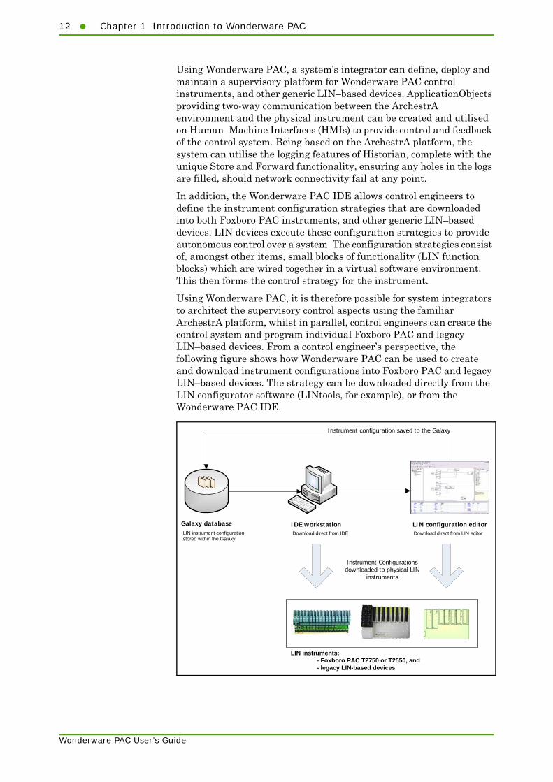
Using Wonderware PAC, it is therefore possible for system integrators to architect the supervisory control aspects using the familiar ArchestrA platform, whilst in parallel, control engineers can create the control system and program individual Foxboro PAC and legacy LIN–based devices. From a control engineer’s perspective, the following figure shows how Wonderware PAC can be used to create and download instrument configurations into Foxboro PAC and legacy LIN–based devices. The strategy can be downloaded directly from the LIN configurator software (LINtools, for example), or from the Wonderware PAC IDE.
IDE workstation
LIN instruments:- Foxboro PAC T2750 or T2550, and- legacy LIN-based devices
Instrument configuration saved to the Galaxy
Galaxy database
Instrument Configurations downloaded to physical LIN
instruments
LIN configuration editorLIN instrument configuration stored within the Galaxy
Download direct from IDE Download direct from LIN editor

Overview13
Wonderware PAC User’s Guide
In Wonderware PAC, the ArchestrA IDE is the start point for any configuration of the LIN control system. Wonderware PAC allows the user to create, manage, and download LIN instrument configuration files from within the IDE, using device configuration object templates. From an instance of one of these objects, the user can launch LINtools (and subsequently other configuration tools) to configure the strategy. All configuration files are automatically associated with the instrument configuration object, and stored in the ArchestrA Galaxy.
In order to communicate with Foxboro PAC instruments (and generic LIN devices), a Wonderware PAC DAServer can be deployed and configured through the IDE to any number of remote nodes. This is accomplished through the use of a DINetwork object, which handles the deployment of the DAServer, including the installation of associated support software and automatic configuration. A DIDevice object, deployed to a DINetwork, provides access to the actual instrument data, supplying the entry point when referencing block fields. Thus the instrument’s process values, alarms, and status is exposed to the ArchestrA framework.
All accesible data within Foxboro PAC instruments and generic LIN devices are avilable through the PAC namespace. This is a complete virtual representation of the data that exists in a set of instrument configurations (offline namespace) and running instrument databases (runtime namespace). An ArchestrA browser plug-in enables the user to browse the namespace across multiple LIN instruments. The namespace is thus browsable and hierarchical and each LIN function block field is accessible through the use of this namespace via a block’s reference string in the format:
<PAC Device Integration object name>.<LIN function block>.<LIN
field>
To provide integration with control and other functions supported within LIN instruments, Wonderware PAC includes a set of ArchestrA ApplicationObjects and symbols, that allow these functions to be driven from the Human-Machine Interface (HMI), and provide simple implementation from a project engineering perspective. A selection of alarms from the LIN instruments are brought up into ArchestrA through these objects, including diagnostic information. An ArchestrA IDE extension provides a fast and easy way of binding (associating) these ApplicationObjects to the correct LIN function blocks.
14 Chapter 1 Introduction to Wonderware PAC
Wonderware PAC User’s Guide
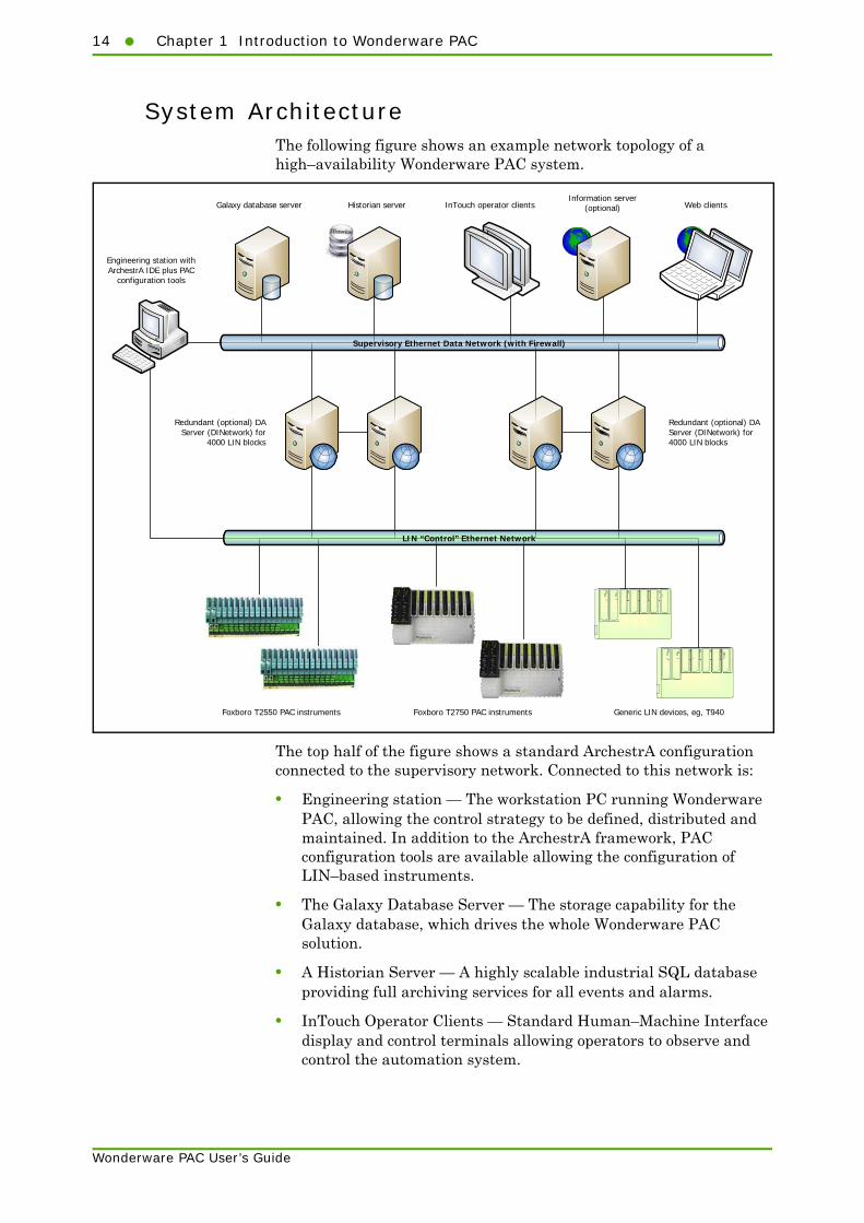
System ArchitectureThe following figure shows an example network topology of a high–availability Wonderware PAC system.
The top half of the figure shows a standard ArchestrA configuration connected to the supervisory network. Connected to this network is:
• Engineering station — The workstation PC running Wonderware PAC, allowing the control strategy to be defined, distributed and maintained. In addition to the ArchestrA framework, PAC configuration tools are available allowing the configuration of LIN–based instruments.
• The Galaxy Database Server — The storage capability for the Galaxy database, which drives the whole Wonderware PAC solution.
• A Historian Server — A highly scalable industrial SQL database providing full archiving services for all events and alarms.
• InTouch Operator Clients — Standard Human–Machine Interface display and control terminals allowing operators to observe and control the automation system.
Galaxy database server Historian server InTouch operator clientsInformation server
(optional) Web clients
Redundant (optional) DA Server (DINetwork) for
4000 LIN blocks
Engineering station with ArchestrA IDE plus PAC
configuration tools
Redundant (optional) DA Server (DINetwork) for 4000 LIN blocks
Supervisory Ethernet Data Network (with Firewall)
LIN “Control” Ethernet Network
Foxboro T2550 PAC instruments Foxboro T2750 PAC instruments Generic LIN devices, eg, T940

Overview15
Wonderware PAC User’s Guide
• Information Server (optional) — Provides remote access server capabilities, allowing the distributed web clients to observe an overall summary and control the system. Detailed examination of some symbols is not possible using the web clients.
• Web clients — Remote clients able to connect to the Information Server using a standard web browser.
Shown in the lower half of the figure is the LIN (or control) network. Multiple Foxboro PAC instruments and generic LIN devices can be attached to this network.
The two networks (supervisory and LIN) are bridged through the DAServers, shown in a redundant configuration in the figure. Each redundant pair of DAServers provides communication to and from LIN function blocks within the PAC instruments and generic LIN devices. The DAServers (DINetwork objects in Wonderware PAC) translate the LIN–based communication in to a format that Wonderware PAC can understand. Each Foxboro PAC instrument or generic LIN device is represented as a DIDevice in Wonderware PAC, and these DIDevices provide the entry point to access the LIN data.
In order to download a strategy to any of the LIN-based instruments, a direct network connection is required between the engineering station and the LIN network as shown in the figure.
Note: The network connection between the engineering station and the LIN network is only required to update the strategy on Foxboro PAC instruments (or generic LIN devices). The network connection is not required at run-time, and can be removed if desired or company policy dictates.
To implement the above, Wonderware PAC-specific object templates are available. These are:
• Foxboro PAC instrument configuration templates. To support the Foxboro PAC instruments, pre-defined instrument configuration templates are available which can be used to store the strategy of an instrument within the Galaxy. The Foxboro PAC instrument templates are:
• $T2750
• $T2550
• Generic LIN template ($GenericLIN) — used to support other legacy LIN-based devices, for which only a blank template is created.
• $PAC_DINetwork template — used to represent a LIN network, and provides the connectivity between the LIN network and ArchestrA.

16 Chapter 1 Introduction to Wonderware PAC
Wonderware PAC User’s Guide
• $PAC_DIDeviceDiag template — used to define the PAC instruments and provide access to the actual instrument data by providing the entry point to individual LIN function blocks. In addition, provides diagnostic information on the PAC instrument, and provides an HMI interface to control and monitor the instrument. This object should only be used for T2550 and T2750 instruments.
• $PAC_DIDevice template — similar to the $PAC_DIDeviceDiag template, but without the diagnostic functionality supported in the T2550 and T2750 instruments. Used to define any generic LIN, or non-Foxboro PAC instrument and provide access to the actual instrument data by providing the entry point to individual LIN function blocks. This object should be used for non-T2550 or T2750 instruments. For T2550 and T2750 instruments, use the $PAC_DIDeviceDiag template instead.
• A collection of ApplicationObjects to map LIN function blocks to an ArchestrA equivalent object. These support the functionality required at the supervisory level (alarming, HMI display and interaction, logging and historising).
Hierarchically, the DINetwork and DIDevice(s) combine as in the following figure, deployed under WinPlatform and AppEngine objects. Each DIDevice has an associated instrument configuration (defined using the object editor).
Detailed health and diagnostics information is available from a comprehensive DIDevice symbol which brings many of the status and alarm blocks from a LIN instrument into the ArchestrA environment.
Supported DevicesThe following instruments are directly supported in Wonderware PAC:
• T2750
• T2550
• Generic LIN, providing support for any legacy LIN-based device.
System Limits17
Wonderware PAC User’s Guide
System LimitsThe recommended maximum number of objects supported by Wonderware PAC, per AppEngine is 2500, where:
• 20% of these (500 objects) are customer objects, and
• 80% of these (2000 objects) are Wonderware PAC objects.
The exact ratio of customer objects to the provided Wonderware PAC objects is not important and the figures above just reflect typical usage.
If the limit of 2500 objects is exceeded, the AppEngine on the WinPlatform which the DINetwork (DAServer) is installed can become unstable.
There is no theoretical limit to the number of AppEngines per Galaxy but these recommendations are based on a single AppEngine per WinPlatform.
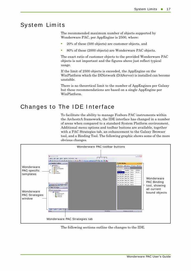
Changes to The IDE InterfaceTo facilitate the ability to manage Foxboro PAC instruments within the ArchestrA framework, the IDE interface has changed in a number of areas when compared to a standard System Platform environment. Additional menu options and toolbar buttons are available, together with a PAC Strategies tab, an enhancement to the Galaxy Browser tool, and a Binding Tool. The following graphic shows some of the more obvious changes.
The following sections outline the changes to the IDE.
WonderwarePAC Bindingtool, showingall currentbound objects
WonderwarePAC-specifictemplates
WonderwarePAC Strategieswindow
Wonderware PAC toolbar buttons
Wonderware PAC Strategies tab

18 Chapter 1 Introduction to Wonderware PAC
Wonderware PAC User’s Guide
Menu and Toolbar optionsThree Wonderware PAC-specific toolbar buttons are appended to the main ArchestrA IDE toolbar. The toolbar is displayed by default, but the visibility can be toggled using the View > Toolbars > Main Toolbar menu option.
The four Wonderware PAC toolbar buttons are shown in the following figure.
The four Wonderware PAC buttons are explained in further detail below.
• PAC Strategies — Displays the PAC Strategies instrument view window, allowing the creation and management of instrument strategy configuration files. Refer to "PAC Strategies Tab" on page 22 for further information.
• PAC Binding — Displays the PAC Binding dockable window, if hidden, allowing the browsing and automatic association between LIN function blocks and ArchestrA objects. By default, the PAC Binding window is displayed on the right-hand side of the IDE, but can be repositioned or hidden. Refer to "PAC Binding Tool" on page 24 for further information.
• Configure UStoreForward — Displays the UStoreForwardConfig window that is used to automatically create Store and Forward mapping files (.usf files) between ArchestrA objects and LIN fields. With this information, gaps in Historian and the Wonderware Alarm Database can be restored from Foxboro PAC instrument’s .uhh files using the Store and Forward feature. Refer to "Configuring Store and Forward" on page 105 for further information.
• Manage EurothermSuite Applications — Allows the editing and publishing of Managed InTouch applications. Refer to "Using Managed Applications (EurothermSuite Project Link)" on page 26 for further details.
PAC Strategies.Displays the PACStrategies window.
Help Topics (F1).Displays the standardArchestrA help.
PAC Binding. Displaysthe PAC Binding tool.
Configure UStoreForward.Displays the UStoreForwardconfiguration window.
Manage EurothermSuite Applications.Displays the EurothermSuite Project Linkwindow.

Changes to The IDE Interface19
Wonderware PAC User’s Guide
Like the toolbar buttons, the View menu also allows control of the visibility of the PAC Strategies tab and the PAC Binding tool.
The FoxboroPAC menu also duplicates two of the buttons on the toolbar, allowing you to:
• Configure UStoreForward
• Show the EurothermSuite Project Link window in order to make, edit and publish managed applications. Refer to "Using Managed Applications (EurothermSuite Project Link)" on page 26 for further details.
The LIN Connection Setup tool can be launched from within the PAC Strategies window, as shown in the following figure.
Click to showthe PACStrategiestab or PACBinding tool
Click this button tolaunch the LINConnection Setuptool

20 Chapter 1 Introduction to Wonderware PAC
Wonderware PAC User’s Guide
Wonderware PAC Object TemplatesWhen creating a new Galaxy, Wonderware PAC-specific templates should be imported. They are installed to the template toolbox window within the folder tree. Specifically, they are installed:
• Device Integration templates ($PAC_DIDeviceDiag and $PAC_DINetwork) — installed to the Device Integration folder (with the exception of the $PAC_DIDevice, which is installed to the PAC Base folder).
• Wonderware PAC base templates — installed to the PAC Base folder. These are generally only used for custom template creation.
• ApplicationObject templates ($PAC_PID, $PAC_VLV2IN and $PAC_AI_UIO, for example) — installed to the FoxboroPAC / Application folder
• Foxboro PAC and generic LIN instrument configuration templates ($GenericLIN, $T2550 and $T2750)— installed to the FoxboroPAC / Strategies folder
The following figure shows the location of the Wonderware PAC-specific templates.
Note: The $PAC_DIDevice template is located within the PAC Base folder tree. Use the $PAC_DIDevice instance to communicate with non-Foxboro PAC instruments (that is, instruments other than the T2550 and the T2750). For T2550 and T2750 instruments, the use of a $PAC_DIDeviceDiag instance (under the Device Integration folder tree) is recommended.
Device Integration objects($PAC_DIDeviceDiag and $PAC_DINetwork)
Wonderware PAC ApplicationObjects
Instrument configuration templates($GenericLIN, $T2550, and $T2750)
PAC Base templates. Generally only usedwhen building custom templates.

Changes to The IDE Interface21
Wonderware PAC User’s Guide
The following table lists the primary Wonderware PAC object templates.
In addition to the primary Wonderware PAC object templates, a variety of ApplicationObject templates are supplied and continually being added, matching many of the blocks found inside a Foxboro PAC instrument. These include a varity of analogue and digital control function templates. For full information on each Wonderware PAC object, refer to the online object help within the IDE, retrieved in the usual manner.
Template Description
$T2750 A PAC instrument configuration template for the T2750 controller.
$T2550 A PAC instrument configuration template for the T2550 controller.
$GenericLIN A generic LIN device template for any legacy LIN-based instruments or displays.
$PAC_DINetwork A Device Integration Network template providing information to the Galaxy about the LIN network’s configuration. Deploying this template installs and configures a PAC DAServer to a remote node.
$PAC_DIDeviceDiag A device template that defines the PAC instrument on the LIN network and provides access to the actual instrument data by providing the entry point to individual LIN function blocks. Thus the instrument’s process values, alarms, status, etc, are exposed to the ArchestrA framework.
The $PAC_DIDeviceDiag template also provides diagnostic information for the instument, and provides a means to support HMI control and monitoring.
Note: The $PAC_DIDeviceDiag can only be used with PAC instruments (which have in-built support for the neccessary diagnostic blocks). Other instruments should use the $PAC_DIDevice device integration object.

22 Chapter 1 Introduction to Wonderware PAC
Wonderware PAC User’s Guide
PAC Strategies TabA Wonderware PAC–specific tab showing all instrument configuration strategies can be found in the Application Views window, called PAC Strategies. This provides a single location to find all strategies for PAC and generic LIN instruments.
The instrument configurations located within the PAC Strategies tab, can be defined, maintained, configured and subsequently downloaded to the instrument. Setup of the local LIN network can be performed using the LIN Connection Setup tool, available by clicking the LIN Connection Setup button at the top of the PAC Strategies tab.
Note: Instrument configurations are not deployed to remote devices through the ArchestrA framework, and consequently they are only visible in the PAC Strategies and Derivation tabs. They are not visible in the Deployment tab. Only DIDevice instances that reference an instrument configuration listed in the PAC Strategies tab can be deployed. Instrument configurations can be downloaded to physical instruments, however, using the IDE or LINtools.
Click to launch the LINConnection Setup tool
Instrumentconfiguration templates
PAC Strategies tab
Extract LIN Projectdrop-down

Changes to The IDE Interface23
Wonderware PAC User’s Guide
The Extract LIN Project drop-down located at the top of the PAC Strategies tab provides the ability to export the configuration files from PAC Startegy Objects to an Operations Server and Viewer (OPSS) project. If clicked, the user can select the location of the project root (or create a new one) to export the strategy, as shown in the following figure.

24 Chapter 1 Introduction to Wonderware PAC
Wonderware PAC User’s Guide
LIN Data BrowserTo facilitate the manual binding of Foxboro PAC instruments (or generic LIN devices) to ArchestrA objects, a tab on the Galaxy Browser called LIN Data Browser, is available. This allows browsing of the namespace covering all Foxboro PAC and generic LIN instruments defined within a Galaxy, and is available whenever the configuration of an attribute requires a reference string to be entered.
PAC Binding ToolManually linking individual Foxboro PAC instrument (or generic LIN devices) blocks to ArchestrA object attributes is an essential operation at times, especially when making changes to an existing configuration. However, it can also be a time consuming task if the links are being made by hand, or even when using the LIN Data Browser within the Galaxy Browser tool.
To increase productivity, the PAC Binding tool can automatically bind a predefined set of LIN function block fields on a Foxboro PAC instrument to an instance of an ApplicationObject within ArchestrA.
In addition, once one object has been bound, a facility exists to export this information from the Galaxy to a comma separated value (csv) file. The exported file can be used as a template to create more complex setups. The file can be edited in any editor that supports the csv file type (Microsoft Excel® or Notepad, for example), duplicated or modified, and then reimported into the Galaxy using the PAC Binding tool. This allows, for example, multiple PAC instrument blocks to be bound to multiple object instances in an extremely efficient manner.

Changes to The IDE Interface25
Wonderware PAC User’s Guide
Note: If a particular object referenced in the imported file already exists in the Galaxy, the entry is ignored and the next line is processed. Existing objects are not overwritten or modified.
The feature allows system integrators to quickly create those objects required for the supervisory control aspects, even if the strategies within the LIN instruments have yet to be created and downloaded to the instruments.
LIN Connection Setup ToolTo enable the local engineering workstation to connect to the appropriate local LIN network, the LIN Connection Setup tool allows a user to specify which LIN network the engineering workstation should communicate with. The list of available connections is automatically generated based on the instrument configurations within the Galaxy, and any existing configuration already on the workstation. The configuration of the LIN network at a remote DAServer node is automatically configured when the DAServer is deployed.
Configure UStoreForward ToolThe Store and Forward tool automatically attempts to fill in gaps in Historian that may exist, typically created when the data flow from an instrument to ArchestrA is interrupted. The Store and Forward tool examines .uhh files FTP’d from Foxboro PAC instruments, and compares the contents of these files against the data held in Historian. Where possible, Store and Forward then attempts to fill in the gaps if the data is available in the .uhh files.
Event messages (usually generated when a LIN function block enters an alarm state) for blocks within a Foxboro PAC strategy can also be forwarded to the Wonderware Alarm Database for the associated area.

26 Chapter 1 Introduction to Wonderware PAC
Wonderware PAC User’s Guide
For this mechanism to work, there needs to be a mapping of LIN fields to Historian tags and LIN Recording Groups to ArchestrA Areas for the Wonderware Alarm Database. Store and Forward uses a .usf configuration file that provides this mapping information. The Configure UStoreForward tool, accessed from the ArchestrA toolbar or Foxboro PAC menu, automatically creates this .usf file by examining the fields that are in a Recording Group within a Foxboro PAC instrument strategy and maps these against the ArchestrA objects that have the History Extension enabled.
An example of theConfigure UStoreForward window is shown below.
Using Managed Applications (EurothermSuite Project Link)
Traditionally, an end-user HMI (InTouch application) was configured using Eurotherm’s Project Organiser, which allowed the launching of WindowMaker to customise the graphics, symbols and text outside of Wonderware PAC.
However, this approach meant the large collection ArchestrA symbols could not be used in the published InTouch application.
From release 8.0 of Foxboro PAC, it is possible to create new EurothermSuite Projects that are known as "Managed applications" (rather than Published applications), which can be simply edited from within the Archestra IDE, and take full advantage of the suite of ArchestrA symbols. The creation of such projects is performed using the traditional New Eurotherm Project Wizard, and then managed and edited using the Eurotherm Suite Project Link window within the ArchestrA IDE.

Changes to The IDE Interface27
Wonderware PAC User’s Guide
To launch the EurothermSuite Project Link window, click on the Manage EurothermSuite Applications toolbar button, or select Configure EurothermSuite Apps in the FoxboroPAC menu. The EurothermSuite Project Link window is displayed, as shown in the following example.
When the EurothermSuite Project Link window is first opened, the projects stored in the default location of C:\EuroPS are scanned and listed. This path can be changed by updating the contents of the Full path to the root of all projects field and clicking the Refresh button. Any Intouch applications associated with the projects are also shown in the InTouch Application column. Supplementary information is shown in brackets, if applicable. Next to each project are three buttons (Make, Edit and Publish) which perform the following functions when clicked:
List ofEurothermSuite
Projects found inthe root folder
(default ofC:\EuroPS)
Log and messagewindow
Path whereEurothermSuite
projects arestored
Name of Project
InTouch application name. If thisdoesn’t exist in the Galaxy yet, theMake button is available to click.
Make managedapplication
Edit application
Publish app
Refresh list of projects displayed at the top Close this window

28 Chapter 1 Introduction to Wonderware PAC
Wonderware PAC User’s Guide
• Make — This button is only available if the current Galaxy does not contain this project as a managed application; if it is not available, the button is replaced with n/a. Clicking this button makes a managed application with the same name as the Project. This task may take several minutes to complete whilst the template application is copied into the Galaxy. An example is shown in the figure below.
• Edit — This button allows the InTouch application to be edited. A confirmation dialogue is displayed before WindowMaker is launched.

Wonderware PAC Workflow29
Wonderware PAC User’s Guide
• Publish — This button publishes the InTouch application into the correct folder in the correct project. A confirmation window is displayed before the selected application is published.
The tool then publishes the InTouch application, which may take a few minutes to complete. An example of a completed publish operation is shown in the following figure.
Once the application has been published, it can be deployed to the computers in the system, if required, using the deploy function from within Project Organiser.
Wonderware PAC WorkflowUsers who are familiar with LIN-based instruments and devices will notice a change in workflow. In particular, the Galaxy is used to store the instrument configuration files, rather than the files being stored locally on a workstation. Downloading of the strategies can be performed both within LINtools, or directly from within the ArchestrA IDE. The editing of the instrument configuration files is always invoked using the ArchestrA IDE, and not edited directly with tools such as LINtools which have been launched independently from the Start menu. Strategy files can be lost if they are edited in instances of LINtools not launched from within the IDE on a Wonderware PAC installed workstation.

30 Chapter 1 Introduction to Wonderware PAC
Wonderware PAC User’s Guide
The basic workflow, which is a top-down methodology, is as follows:
1 Create an instance of a Foxboro PAC instrument configuration object and define the strategy.An instance of a Foxboro PAC instrument configuration template is a place-holder to allow the configuration of the instrument’s strategy to be stored within the Galaxy, and to define the namespace for a PAC instrument Device Integration Object (step 4). Configure the object with the desired port name and node address so the DAServer (DINetwork object) can connect to the instrument later on.
Multiple instrument configurations can be created at this stage, prior to continuing to step 2. This allows a system integrator to define place-holders for the instrument configurations, which can be managed and incrementally developed at a later stage by control engineers.
Once the instance of the PAC instrument configuration template is created, the strategy can be defined. Using the ArchestrA IDE, launch LINtools to edit the instrument configuration for the device. Other supporting configuration software tools can then be launched from within LINtools. The instrument configurations, which include the strategies, are located in the PAC Strategies tab.
After the strategy has been created, the local communication configuration is defined using the LIN connection setup tool. This configures the communication from the engineering workstation to the LIN instruments, enabling the instrument configuration to be downloaded to the LIN instruments. The download can be performed from either within LINtools or the ArchestrA IDE.
2 Create an instance of the platform for the PAC DAServer.A PAC DAServer is deployed to an Application Server AppEngine. Create a WinPlatform and AppEngine object in the normal manner. The PAC DAServer will be deployed and configured to this platform.
3 Create a PAC network object.A PAC device integration network object (PAC DINetwork) provides information to the Galaxy about a LIN network’s configuration. Deploying this object to a remote AppEngine installs and configures a PAC DAServer to the remote (or local) node as well. It provides the connectivity between the LIN network and ArchestrA. To the network object, device integration (DIDevice) instances are deployed to faciliate communication with the physical instruments.
Note: Only deploy one DA Server (PAC DINetwork object) to any single node.

Wonderware PAC Workflow31
Wonderware PAC User’s Guide
4 Specify which instruments the DINetwork can access.For each physical instrument connected to the network, create an instance of a DIDevice object. This object provides access to the actual instrument data by providing the entry point to the individual LIN function blocks. Thus, the instrument’s process values, alarms, status, etc, are addressable by the ArchestrA framework. A DIDevice object brings together the instrument configuration defined in step 1 to the DINetwork object defined in step 3. It also provides the full namespace for the Galaxy Browser extensions.
5 Bind PAC instrument blocks to ArchestrA object instances.For a deployed DIDevice instance to expose its runtime values (process values, alarms, status, etc), the LIN data must be mapped – or bound – to an ArchestrA object’s User Defined Attributes (UDAs). Equivalent ArchestrA objects (to those blocks in the LIN instrument) are first created and then bound to the LIN function blocks. This binding can be performed manually, by the use of the namespace browser, or automatically by the PAC Binding tool. The PAC Binding tool can also create the object instances and bind the attributes on mass using the import feature.

32 Chapter 1 Introduction to Wonderware PAC
Wonderware PAC User’s Guide

33
Wonderware PAC User’s Guide
Chapter 2
Wonderware PAC Basics
This chapter provides an overview of creating ArchestrA objects that, when deployed, connect to Foxboro PAC instruments (or other legacy LIN–based instruments) on a LIN network and expose the LIN data to the ArchestrA framework. A series of walkthrough examples are used to aid understanding.
This chapter has the following sections:
• Overview
• Stage 1: Creating A PAC Instrument Configuration
• Stage 2: Creating the Execution Platform for the PAC DAServer
• Stage 3: Creating a DINetwork (LIN Network Object)
• Stage 4: Adding DIDevices (Instruments) to the DINetwork
• Stage 5: Binding LIN Data to ArchestrA Application Objects
• Post–Configuration Procedure
• Improving Productivity with the PAC Binding Tool

34 Chapter 2 Wonderware PAC Basics
Wonderware PAC User’s Guide
OverviewTo deploy a Foxboro PAC instrument within the ArchestrA framework, a series of steps must be followed to expose an instrument’s LIN data to the ArchestrA framework. The necessary steps to create such an installation are shown in the figure below:
Stage 1: Creating A PAC Instrument Configuration
This section explains how to create an instance of a Foxboro PAC instrument configuration, how to edit the strategy, and finally download it to the instrument. In addition, this section describes the method to change the instrument version, and to configure the LIN connection to enable local communication with the LIN device.
An instance of a PAC strategy object represents the configuration of an instrument. It contains the complete strategy definition for the device, allowing the Galaxy to store the information and build the namespace necessary for successful communication between any Foxboro PAC instrument (or generic LIN device), and an ArchestrA object. The configuration can be downloaded directly to a Foxboro PAC instrument from within the ArchestrA IDE framework, or by using LINtools – the primary strategy editor.
Two primary supported Foxboro PAC instrument configuration templates are available, the:
• $T2750 template, representing the T2750, and the
Create an instance of a PAC instrument
configuration
Prepare a node for the Device
Integration Network
Create an instance of a Foxboro PAC instrument configuration (eg, T2750) to allow the strategy to be stored within the Galaxy.
Prepare a node onto which the Device Integration Network object (and Foxboro PAC DA Server) can be deployed (in the next step).
Create an instance of a DINetwork object
Create an instance of a Device Integration Network. This represents a LIN network, and provides the connectivity between the LIN network and ArchestrA.
Create an instance of a DIDevice object
Create a Device Integration object, representing the physical LIN instrument, providing an entry point to the individual LIN blocks and fields.
Bind blocks from the PAC instrument to ApplicationObjects
Create the mapping between the PAC instrument’s tags, alarms and process values to an ArchestrA ApplicationObject.
5
4
3
2
1

Stage 1: Creating A PAC Instrument Configuration35
Wonderware PAC User’s Guide
• $T2550 template, representing the T2550.
When either of these instrument configurations are created, Wonderware PAC automatically creates an appropriate blank strategy with the correct the device type defined and of the latest version (based on the latest version supported by LINtools).
To deploy a LIN–based instrument other than a T2550 or T2750, the generic template, $GenericLIN, should be used instead. The process to create a configuration for a generic LIN device is similar to that for a Foxboro PAC instrument, except that the instrument type and version need to be defined at the time of strategy creation.
Note: If the strategy for a T2750 or T2550 instrument has already been created, but the instrument has not yet been added to the Galaxy (the strategy was created before ArchestrA was installed, for example), then a special procedure must be followed to import the strategy into the galaxy. Refer to the "Importing Existing LIN Strategies to The Galaxy" on page 111 for more information.
The following procedure provides a step–by–step example of creating a Foxboro PAC instrument configuration instance for a T2750 device.
To instantiate a new Foxboro PAC instrument configuration
1 Ensure the PAC Strategies view window is visible. To view the PAC Strategies view window:
• select the PAC Strategies tab, or
• click the PAC Strategies toolbar button, or

36 Chapter 2 Wonderware PAC Basics
Wonderware PAC User’s Guide
• select PAC Strategies from the View menu.
The following figure shows the three ways of viewing the PAC Strategies view window.
View the PAC strategies tab by clicking in the View menu ...
... clickingthe PACStrategiestoolbarbutton ...
... or clicking the PAC Strategies tab

Stage 1: Creating A PAC Instrument Configuration37
Wonderware PAC User’s Guide
2 In the Template Toolbox, expand the Strategies folder within the FoxboroPAC folder, and drag–and–drop a $T2750 instrument configuration template from the toolbox to the PAC Strategies view window, as shown in the following figure.
The default name for the new instrument configuration is T2750_nnn, where nnn is a sequential number starting from 001. The PAC instrument can be renamed in the usual manner within ArchestrA, if required.
Note: Instrument configurations are not deployed to remote devices through the ArchestrA framework, and consequently they are only visible in the PAC Strategies and Derivation tabs. They are not visible in the Deployment or Model tabs. Only DIDevice instances that reference an instrument configuration listed in the PAC Strategies tab can be deployed. Instrument configurations can be downloaded to physical instruments, however, using the IDE or LINtools.
Drag the $T2750instrumentconfigurationtemplate to thePAC Strategieswindow, as shown
PAC Strategies tabselected

38 Chapter 2 Wonderware PAC Basics
Wonderware PAC User’s Guide
3 Check out and edit the new instrument configuration so it can be configured. As with all ArchestrA instances, double–click on the object to check it out from the Galaxy and open it. The instrument configurator opens in the main workspace of the IDE, with the single PAC Strategy Instrument Configuration tab displayed, as per the following figure.
The PAC Strategy Instrument Configuration tab allows configuration of the necessary information that the PAC DAServer needs to know in order to connect to the instrument later on.
4 In the LIN Protocol Name field, enter the appropriate name for the LIN network, if the default of NET is not appropriate.
5 In the Node Address (Hex) field, enter a unique node address for the instrument, corresponding to the configuration switches on the T2750. The entry should be a two–digit hex value between 01 and FE.
Note: For Foxboro PAC instruments (T2750 or T2550), use only even node address numbers. Odd numbers are reserved for redundant pairs. For Generic LIN devices, odd or even node addresses are valid.
If the node address matches that of another device configured in the Galaxy, a warning is given to the user during the object check in process.
Three other instrument fields are automatically completed, as follows:
• The Instrument Type field is based on the template used to create the instance. In this case, T2750.
Editable fields

Stage 1: Creating A PAC Instrument Configuration39
Wonderware PAC User’s Guide
• The Instrument Version is based on the version of LINtools installed, and selects the most up–to–date version available in the first instance. At the time of the first release of Wonderware PAC, this is v1.0 for a T2750 instrument, and v7.0 for a T2550 instrument.
• The Default DBF field is set to T2750.DBF. This can be changed if the user wishes, and must be manually configured if the instrument is a generic LIN device. The Default DBF is the database that is downloaded and run in the instrument. The Default DBF field can be changed within LINtools using the File > Instrument Folder Properties menu command.
Note: If a generic LIN device were being created, the Instrument Type, Instrument Version and Default DBF fields are blank. These can be set by using the Instrument Folder Properties option within LINtools.
Three additional buttons are available to continue configuring the instrument. They are:
• Run LINtools — Click this button to run LINtools and to automatically open the default DBF file. Additional configuration tools can be launched from the Tools menu from within LINtools. Once the strategy has been defined, close LINtools to return to the IDE. When the instrument instance is checked back into the Galaxy, any configuration files created by LINtools and additional configuration tools are also saved. Refer to "Editing the Strategy for a Foxboro PAC Instrument" on page 40 for further information.

40 Chapter 2 Wonderware PAC Basics
Wonderware PAC User’s Guide
• Instrument Options — Click this button to display the LIN Instrument Options window. Use this window the modify various instrument-specific parameters. On the Instrument Options tabs, this includes options such as configuring ports, time zone, and the archiving of recorded data. On the Network Settings tab, Ethernet-related parameters for the instrument can be configured, including DHCP or static IP address configuration.
• Download — Click this button to download the instrument’s strategy to the physical device. The engineering workstation needs to be configured to communicate with local LIN instruments before this operation can be successfully completed. Refer to "Using the LIN Connection Setup Tool" on page 44 for further information.
Editing the Strategy for a Foxboro PAC Instrument
The process for launching LINtools, and other LIN–based software support tools to create strategies for Foxboro PAC instruments (or generic LIN devices) is critical.
The method of editing a strategy for Foxboro PAC instruments or Generic LIN devices is nearly identical. The only difference is that for Foxboro PAC instruments, a predefined LIN database with an appropriate LIN header block is created. For Generic LIN devices, the database is blank, and the appropriate device type and version must be defined by the user.
To launch LINtools Engineering Studio and edit the strategy, open the instrument configurator by checking out the instrument configuration. From here, click the Run LINtools button. LINtools launches with the correct strategy file opened.

Stage 1: Creating A PAC Instrument Configuration41
Wonderware PAC User’s Guide
Important: Always launch any LIN software support tools (including LINtools) from within the ArchestrA IDE. Making changes to LIN strategies by launching LIN software support tools outside of the ArchestrA IDE (eg, from the Start menu) will not be reflected within the galaxy and may cause any changes to be discarded.
When LINtools Engineering Studio is running, any of the additional software support tools (eg Modbus Tools) can be launched from the tools menu from within the LINtools user interface.
If the user decides to open a read–only version of the configuration from the Galaxy, or if another user has already checked out the instrument configuration, then this is indicated in LINtools by the addition Read Only in the title bar. In this mode, LINtools opens the configuration as read–only, so no modifications can be saved. It is possible, however, to download the strategy or go online to the instrument.
Some functionality within LINtools Engineering Studio is disabled when used within the Wonderware PAC environment, as it is not relevant. For example, the Get Me Started and New LIN Instrument Folder options within the File menu are not available.
If a strategy for a Generic LIN device is being defined, ensure the instrument type and version is set using the Instrument Folder Properties window (select Instrument Folder Properties from the File menu within LINtools). An example is shown in the following figure.
If a strategy already exists outside of the Wonderware PAC environment (the strategy was previously defined, for example), then it is possible to import an existing strategy into the Galaxy. It is important that a strategy is imported into the correct Foxboro PAC instrument configuration type (eg, a T2750 configuration imported into a T2750 instrument configuration instance). Refer to Appendix D, "Importing Existing LIN Strategies to The Galaxy," for information on how to complete this task.
For Generic LINdevices, set the deviceType and Version usingthese drop–downmenus.
42 Chapter 2 Wonderware PAC Basics
Wonderware PAC User’s Guide
Once the strategy is defined, close LINtools to return to the ArchestrA IDE. Check the instrument instance back into the Galaxy in the normal manner to store the strategy and configuration files in the Galaxy.
Note: The object cannot be checked back into the Galaxy if LINtools is still editing the strategy.
Changing the Instrument VersionBy default, the version of the database for an instrument configuration strategy is the latest major version that LINtools supports for a specific device. There may be circumstances when the user needs an older instrument version (for example, when working with a legacy system).
In these cases, the following procedure can be performed to change the instrument version.
The following procedure shows an example of changing a T2550 instrument from version 7.0 to version 6.0.
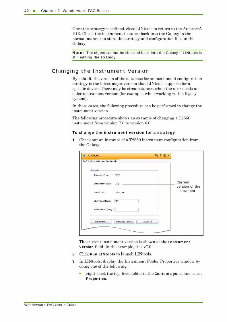
To change the instrument version for a strategy
1 Check out an instance of a T2550 instrument configuration from the Galaxy.
The current instrument version is shown at the Instrument Version field. In the example, it is v7.0.
2 Click Run LINtools to launch LINtools.
3 In LINtools, display the Instrument Folder Properties window by doing one of the following:
• right–click the top–level folder in the Contents pane, and select Properties.
Currentversion of theinstrument

Stage 1: Creating A PAC Instrument Configuration43
Wonderware PAC User’s Guide
• Select Instrument Folder Properties from the File menu.
The Instrument Folder Properties window appears, as shown in the following figure.
4 Click the drop–down menu next to the Version field and select a different instrument version.
Note: The instrument type cannot be changed if the device is a T2550 or a T2750. The Node address cannot be changed, regardless of the type, as this is controlled via the PAC Strategy Instrument Configuration properties within the IDE.
5 Click OK to close the window, and after any other edits are complete, close LINtools.
Current instrumentversion is shownhere
Use the drop–downmenu to show alist of availableversions

44 Chapter 2 Wonderware PAC Basics
Wonderware PAC User’s Guide
6 The PAC Strategy Instrument Configuration page within the IDE is updated with the new version number.
7 Check the instrument configuration in to the Galaxy to save the changes.
Using the LIN Connection Setup ToolWhen a Wonderware PAC DIDevice is deployed to a remote node, the DAServer is automatically configured to permit communication to and from an instrument. However, in order for the IDE engineering workstation to be able to communicate with the local Foxboro PAC instrument (or generic LIN device), the following requirements need to be met:
• the engineering workstation needs to be physically connected to the LIN network
• Communication between the local PC and the LIN network needs to be configured.
The LIN Connection Setup tool can be used to configure the LIN connection between the local engineering workstation and the LIN network.
It is not possible to download a strategy to an instrument unless this procedure is completed. A warning message is displayed to the user if a strategy download operation is attempted, or if LINtools is run without the LIN connection being configured. Once configured, however, downloading of the strategy, going online, and making live changes to a device is possible all from within LINtools, launched from the IDE.
Instrumentchanged toversion v6.0
Advisory thattheconfigurationhas changedand thereforeneeds to bechecked in

Stage 1: Creating A PAC Instrument Configuration45
Wonderware PAC User’s Guide
Note: The LIN Connection Setup tool is not required on remote nodes to which a DINetwork is being deployed. The configuration is automatic in these cases.
To configure the local LIN port:
1 Launch the LIN Connection Setup tool by clicking the LIN Connection Setup button located at the top of the PAC Strategies tab, as shown in the following figure.
The LIN Connection Setup window opens, as shown in the following figure. All configured connections are listed, though in normal situations, this would only consist or one or two entries.
To allow the engineering workstation to communicate with instruments on remote subnets, tick the Enable cross-subnet communication checkbox.
Click here toopen theLINConnectionSetup tool
status area
configurationarea

46 Chapter 2 Wonderware PAC Basics
Wonderware PAC User’s Guide
The Protocol Name, Enabled state, and Node Address (address of local PC on the LIN network), are shown, together with an indicator status column. The icon shown in the Indicator column represents:
2 Locate the desired connection from the list, and enable it by selecting the corresponding check box in the Enabled column.
The Node Address is blank for any ports required in a Galaxy, but not yet configured on the engineering workstation. When the Enabled box is ticked, a node address is automatically chosen. This node address should be manually checked that there is no conflict with another engineering workstation on the supervisory network. The automatically chosen node can be manually overridden by clicking in the Node Address column, in the appropriate port row, and typing the address (in hex between 01 and FE).
Tip: The automatically chosen node address is based upon a check that it does not conflict with any instrument configuration objects or PAC_DINetwork objects already configured in the Galaxy. The address is also always an even number, to avoid any conflict with a redundant processor pair on a Foxboro PAC instrument.
The engineering workstation is now configured to communicate with a LIN network on the chosen port(s). The LIN Connection Setup tool can be used to change the port at any time.
Downloading Strategies to a PAC InstrumentTo download a strategy for an instrument from Wonderware PAC, a network connection from the IDE engineering workstation to the LIN network must exist. In addition, the LIN connection must be configured to allow communication between the engineering workstation and the LIN network. Refer to "Using the LIN Connection Setup Tool" on page 44.
Note: It is not possible to download a strategy to a device unless the local LIN connection has been configured using the LIN Connection Setup.
Icon Description
The connection is required by instruments in the current Galaxy, and is currently enabled.
The connection is required by instruments in the current Galaxy, but is currently not enabled.
The connection is enabled, but its configuration is invalid (such as using the same node address as an instrument in the Galaxy)
<blank> The connection exists on the engineering station but is not required by this Galaxy.
Stage 2: Creating the Execution Platform for the PAC DAServer47
Wonderware PAC User’s Guide
To download the strategy to the device:
• From within the IDE, check out the appropriate instrument configuration, and in the PAC Strategy Instrument Configuration tab, click the Download button.
A window appears confirming the user choice to download the configuration. Click OK to confirm.
• From within LINtools: To download the strategy from within LINtools, perform one of the following:
• Click the Download button on the Contents window.
• Select Download This File from the File menu.
• Right–click on the Instrument folder within the Contents window and select Download Configuration.
• Right–click on the actual instrument (for example, T2750) within the Contents window and select Download This.
• For further information on using LINtools, refer to the LINtools online help or the LINtools Engineering Studio User Guide, HA263001U055.
If there is a problem downloading the strategy to the device, ensure the engineering workstation is physically connected to the LIN network, and that the configured port for the instrument is currently selected using the LIN Connection Setup. If problems are still encountered, refer to the "Troubleshooting at Strategy Download Time" on page 116.
Stage 2: Creating the Execution Platform for the PAC DAServer
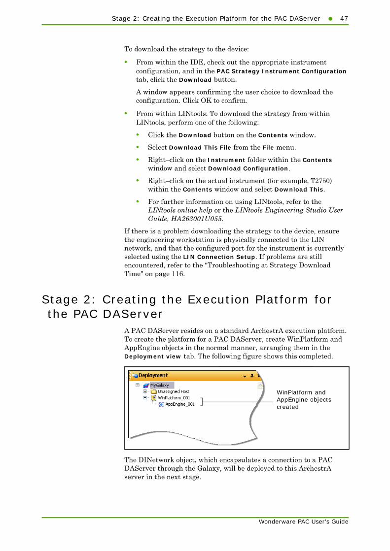
A PAC DAServer resides on a standard ArchestrA execution platform. To create the platform for a PAC DAServer, create WinPlatform and AppEngine objects in the normal manner, arranging them in the Deployment view tab. The following figure shows this completed.
The DINetwork object, which encapsulates a connection to a PAC DAServer through the Galaxy, will be deployed to this ArchestrA server in the next stage.
WinPlatform andAppEngine objectscreated
48 Chapter 2 Wonderware PAC Basics
Wonderware PAC User’s Guide
Note: The first WinPlatform created in a Galaxy must be the Galaxy Repository (GR) node. Therefore, ensure that if the Galaxy is running on a separate node, that this WinPlatform is first defined prior to creating the execution platform for any other node.
A valid license is required for every instance of a deployed PAC DAServer. If no license is installed, the DAServer runs for 120 minutes in a demonstration mode, allowing the configuration to be tested during development. Refer to Appendix A, "Licensing," for further details of the licensing model.
Stage 3: Creating a DINetwork (LIN Network Object)
A DINetwork object instance is deployed under an AppEngine as created in Stage 2. The DINetwork provides information to the Galaxy about the LIN network’s configuration. Deploying a DINetwork object instance deploys (installs and configures) a PAC DAServer to the remote node.
To create a LIN network instance
1 Ensure the Deployment view window is visible. To view the Deployment view window:
• select the Deployment tab, or
• click the Deployment View toolbar button, or
• Press Control + Shift + D keyboard shortcut combination.

Stage 3: Creating a DINetwork (LIN Network Object)49
Wonderware PAC User’s Guide
2 In the Template Toolbox, expand the PAC Device Integration folder, and drag–and–drop a $PAC_DINetwork template to under the Unassigned Host folder in the Deployment view window. The completed step is shown in the following figure.
The default name for the new DINetwork instance is PAC_DINetwork_nnn, where nnn is a sequential number starting from 001. The DINetwork instance can be renamed in the usual manner within Wonderware PAC, if required.
3 Drag the newly created DINetwork instance to the WinPlatform/AppEngine created in Stage 2, as shown completed in the following figure.
Drag the$PAC_DINetworktemplate to theUnassigned Hostfolder, as shown
PAC_DINetworkobject moved fromthe Unassigned Hostfolder to under theAppEngine

50 Chapter 2 Wonderware PAC Basics
Wonderware PAC User’s Guide
4 Check out and edit the new object so it can be configured. As with all ArchestrA instances, double–click on the object to check it out from the Galaxy and open it. The Network Configuration tab is opened which allows the LIN network to be defined, as shown in the following figure.
Specify the LIN protocol name (maximum of 12 alphanumeric characters) and node address (two–digit hex number between 01 and FE) for the LIN network in the LIN Protocol Name and Node Address fields respectfully. If communication across a different subnet is not required, proceed to step 6.
5 If the server needs to communicate with PAC instruments residing on a different subnet, tick the Enable cross–subnet communication check box. An extra field is displayed, PR IP Addresses, but no entries need be made in this field for cross-subnet functionality to be enabled.
Refer to "Enabling Cross-Subnet Communication" on page 139 for additional steps that need to be performed in order to enable cross-subnet communication.
6 The Automatically select network adapter option is ticked by default, and can be left on in the majority of cases (especially true if there is only a single network adapter in the target machine this DINetwork is being deployed to). If this option is deselected, two additional fields are displayed, IP Address and IP Address Mask.
A typical scenario whereby the completion of the IP Address and IP Address Mask fields is recommended when there are two or more network adapters on the target machine, both connected to LIN networks, and both using the same Protocol Name.
The IP Address field configures the IP address to which this port expects to find the network adapter.
The IP Address Mask has special rules for the value entered here. Refer to the LIN Ports Editor control panel applet and additional online help provided for the IP Address Range field.
Note: The IP Address Mask field should not be confused with a subnet mask. They are not the same thing.
Stage 4: Adding DIDevices (Instruments) to the DINetwork51
Wonderware PAC User’s Guide
7 The object now has enough information to be able to create an appropriate LIN port when the object is deployed. Check-in the DINetwork instance. At this stage, the object can be deployed, if desired, and communications can be tested. This results in the PAC DAServer being installed and correctly configured on the remote node. The PAC DAServer is now able to communicate with LIN instruments.
Note: Deploying a DINetwork instance for the first time can take several minutes to complete whilst the PAC DAServer is being installed and configured.
Stage 4: Adding DIDevices (Instruments) to the DINetwork
Having created a DINetwork instance (a PAC DAServer) which provides the interface between the LIN network and the Galaxy, it is necessary to assign the physical instruments (DIDevices) to the DINetwork instance. This ensures the PAC DAServer is able to communicate with the PAC instruments (and any generic LIN devices).
$PAC_DIDevice and $PAC_DIDeviceDiag objects provide the mechanism for a DINetwork to communicate with the LIN device. Each DIDevice instance is associated with an instrument configuration strategy found in the PAC Strategies tab, created in Stage 1.
In addition, a $PAC_DIDeviceDiag object monitors the health of a PAC instrument, and is the recommended DIDevice for Foxboro PAC instruments (T2750 and T2550). Non-Foxboro PAC instruments (legacy and Generic LIN devices) do not support the necessary diagnostic LIN function blocks, and therefore cannot use the $PAC_DIDeviceDiag functionality. In these cases, it is recommended that the $PAC_DIDevice object is used instead.
To add an instrument to a LIN network
1 Ensure the Deployment view window is visible. To view the Deployment view window:
• select the Deployment tab, or
• click the Deployment View toolbar button, or
• Press Control + Shift + D keyboard shortcut combination.
52 Chapter 2 Wonderware PAC Basics
Wonderware PAC User’s Guide
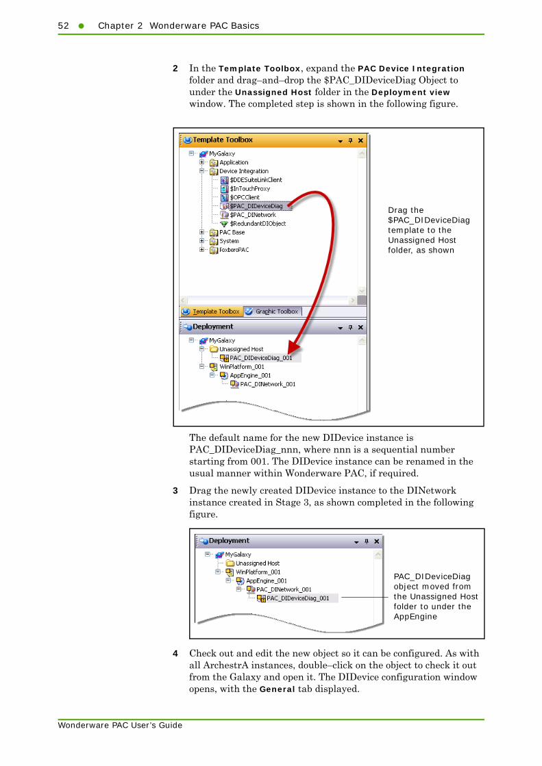
2 In the Template Toolbox, expand the PAC Device Integration folder and drag–and–drop the $PAC_DIDeviceDiag Object to under the Unassigned Host folder in the Deployment view window. The completed step is shown in the following figure.
The default name for the new DIDevice instance is PAC_DIDeviceDiag_nnn, where nnn is a sequential number starting from 001. The DIDevice instance can be renamed in the usual manner within Wonderware PAC, if required.
3 Drag the newly created DIDevice instance to the DINetwork instance created in Stage 3, as shown completed in the following figure.
4 Check out and edit the new object so it can be configured. As with all ArchestrA instances, double–click on the object to check it out from the Galaxy and open it. The DIDevice configuration window opens, with the General tab displayed.
Drag the$PAC_DIDeviceDiagtemplate to theUnassigned Hostfolder, as shown
PAC_DIDeviceDiagobject moved fromthe Unassigned Hostfolder to under theAppEngine

Stage 4: Adding DIDevices (Instruments) to the DINetwork53
Wonderware PAC User’s Guide
5 Under the PAC Instrument field, select the appropriate PAC instrument configuration (strategy) that was configured in Stage 1. This specifies which specific LIN instrument the DIDevice represents.
Each DIDevice object connects to a single PAC instrument object. A PAC instrument object, may however, be used by multiple DIDevice objects.
Select the instrument configurationfrom the drop–down list

54 Chapter 2 Wonderware PAC Basics
Wonderware PAC User’s Guide
6 If the instrument in step 5 above is a legacy device (Generic LIN), then skip this step and proceed directly to step 7. The following step prepares the object for use with the diagnostic symbol. Refer to Chapter 3, "Instrument Diagnostics," for further information.
Select the UDAs tab and locate and select the Simplex [$PAC_DIDeviceDiag] entry in the Inherited UDAs section.
Locate the True/False checkbox, and tick appropriately depending on whether the Foxboro PAC Instrument has a single processor (ticked), or a duplex processor (unticked).
7 Check-in the DIDevice instance to the Galaxy. Other objects within the ArchestrA framework can now access the LIN data through this DIDevice object. To bind the LIN data to an ArchestrA object, refer to the next section.
Working with RedundancyRedundancy within Wonderware PAC works in the standard ArchestrA manner utilising the $RedundantDIObject. A DAServer can be installed in a redundant configuration, and instances of the $RedundantDIObject can be created, configured to reference two DIDevice (PAC instrument or generic LIN) instances.
Select the Simplex UDA ...
... and tick the checkbox according to whether the instrument is operating in a simplex mode (ticked) or a duplex mode (unticked).
UDAs tab selected
Stage 5: Binding LIN Data to ArchestrA Application Objects55
Wonderware PAC User’s Guide
In a situation where redundancy is not required, the instrument diagnostic symbol for a DIDevice can be attached to the DIDevice itself (refer to "Instrument Diagnostics" on page 75 for details on the diagnostic symbol), providing diagnostic information for the DIDevice. In the case of a redundant setup, however, the instrument diagnostic symbol should be attached to the $RedundantDIObject instead, and thus continues to provide diagnostic information on the DIDevice regardless of a failure of a PAC DAServer.
Monitoring of the redunancy status can be performed using the standard ArchestrA RedundantDIObjectDisplay symbol. The primary and backup DIDevices can be referenced from this symbol, thus providing an HMI interface to the redundancy status for the DIDevice.
For further information on working with redundancy within the Wonderware PAC framework, refer to the System Platform documentation, "Working with Redundancy" Chapter in the Application Server User’s Guide.
Stage 5: Binding LIN Data to ArchestrA Application Objects
When a Wonderware PAC ApplicationObject is created, upon instantiation, a set of User–Defined Attributes (UDAs) need to be linked to LIN field references in order to produce a fully functional and deployable object. The process of performing this linking is referred to as binding. Without the binding operation, the runtime values within a LIN instrument cannot be exposed to the Wonderware PAC environment.
The process of binding writes a predefined set of LIN function block fields to the InputSource or OutputSource fields of a corresponding set of attributes on an instance of a particular Wonderware PAC object.
Once an ApplicationObject has been bound, the LIN data can be presented to HMIs allowing a user to view and interact with the instrument.
There are three ways to perform this binding:
• Manually, by typing the PAC instrument’s reference string into an ApplicationObject instance’s InputSource or OutputSource field
• Semiautomatically, by using the Galaxy Browser to view and select the relevant LIN field
• Automatically, by using the PAC Binding Tool
The technique used to bind the LIN data to an object is a user–choice, largely dependant upon the nature of the binding task. The following examples show each method, and when each method may be the most suitable choice.

56 Chapter 2 Wonderware PAC Basics
Wonderware PAC User’s Guide
Manually Binding ObjectsTo manually bind LIN function blocks to an ArchestrA object instance attribute, the reference string of the LIN function block must be known. If only a single bind is required, manually entering the data is one of the quickest method to create the bind.
For this example, a PAC_PID object is used. The aim is to map the PV value in the LIN PID block to the PV attribute in the PAC_PID ApplicationObject. The following assumptions are made:
• the DIDevice to which the physical instrument is associated with is called PAC_DIDeviceDiag_001.
• A PID block already exists in a strategy for an instrument configuration, with the name of MyPID.
• The MyPID block has a field called PV, representing the process value. This is a standard field for all LIN PID blocks.
The reference string for the PV block within the PAC instrument is therefore:
PAC_DIDeviceDiag_001.MyPID.PV
This reference string will be entered manually in to the input extension Source field for the PAC_PID object in the following example.
To manually bind an object
1 Create an instance of a PAC_PID object, check it out and open for edit within the IDE. In the example, the PAC_PID object is called PAC_PID_001.

Stage 5: Binding LIN Data to ArchestrA Application Objects57
Wonderware PAC User’s Guide
2 Select the Extensions tab to view the Extendable attributes, as shown in the following figure. These attributes are automatically created during the creation of the instance of the PAC_PID ApplicationObject.
3 Scroll the list of Extendable attributes until the PV attribute is visible.
4 Highlight the PV attribute and locate the Source text entry box in the Input extension group, as shown in the following figure.
Highlight the PV attribute... ... then click in the Source fieldwithin Input extension group.

58 Chapter 2 Wonderware PAC Basics
Wonderware PAC User’s Guide
5 In the Source field within the Input extension group, enter the reference string determined earlier on. The following figure shows this completed.
The binding of the PAC instrument’s PV value to the ArchestrA PID object is complete. The object can now be checked back in. In order to check the binding, the Object Viewer utility can be opened and the PAC_PID_001.PV can be added as an Attribute Reference to a Watch window. If the configuration is correct, the live PV value is displayed. For information on the Object Viewer utility, see the Object Viewer User’s Guide.
If the reference string is not known, it can be looked up using the LIN Data Browser. Refer to the next section, "Using the LIN Data Browser to Bind Objects" on page 58.
Using the LIN Data Browser to Bind ObjectsWonderware PAC provides an additional tab, within the Galaxy Browser, which allows browsing of the namespace specific to PAC instruments and other generic LIN devices. This facility can be used to help create a bind between a PAC instrument and a Wonderware PAC object, and eliminates the need to know (or work out) the reference string. The procedure is very similar to that for manually binding objects. Therefore, refer to "Manually Binding Objects" on page 56 and follow the procedure up to, and including, step 3. Then continue with the procedure below.
Manually entered binding

Stage 5: Binding LIN Data to ArchestrA Application Objects59
Wonderware PAC User’s Guide
To look up a reference string using the Namespace Browser tool:
1 Highlight the PV attribute and click the ellipses button next to the Source text entry box in the Input extension group, as shown in the following figure.
Highlight the PV attribute... ... then click the ellipses button forthe Input extension group.

60 Chapter 2 Wonderware PAC Basics
Wonderware PAC User’s Guide
2 The Galaxy Browser window displays. Click on the LIN Data Browser tab to display the namespace for all LIN instruments, as shown in the following figure.
The LIN Data Browser window is divided into two. In the left–hand section of the window, all the known DIDevice instances are shown. If any PAC strategies are associated with the instruments, the PAC strategy is shown next to the DIDevice. In the example above, the DIDevice PAC_DIDeviceDiag_001 has the PAC strategy, T2550_001 associated with it; the PAC_DIDeviceDiag_002 has the PAC strategy T2750_001 associated with it, and so on.
Note: Redundant DIDevices are only shown in the left-hand section of the window if the RDI object references PAC DIDevices.
On the right–hand section of the window, all the known LIN function blocks within the selected DIDevice’s PAC strategy are shown. In the example above, the PAC_DIDeviceDiag_001 has the strategy T2550_001, which has, amongst other blocks, the MyPID block. Information for each of the LIN function blocks can be found in the LIN Blocks Reference Manual.
LIN Data Browser tab MyPID LIN block
Click to show LIN block fields that are writable
Click to show LIN block fields that are read-only

Stage 5: Binding LIN Data to ArchestrA Application Objects61
Wonderware PAC User’s Guide
Note: The blocks and fields shown in the right–hand section of the window do not contain live data. The information is taken from the configuration files stored within the Galaxy. To view live data, use the Object Viewer utility. For information on using the Object Viewer, see the Object View User’s Guide.
The content of the right–hand section of the window can be filtered in two ways. Firstly, the field data type can be specified in the Field Type Filter drop down menu, so for example, only those fields that are of the Boolean data type, or Integer data type are shown.
The second type of filter that can be applied is to show only those fields that are writable, or read–only. Use the small buttons to the right of the Field Type Filter drop down menu to toggle the filter mode. When a filter is applied, the button highlights in orange. The filtering functions as shown in the following table.
Buttons Description
No filter applied. Both writable and read-only LIN function blocks are shown.
Only write able LIN function block fields are shown – read-only fields are hidden.
Only read-only LIN function block fields are shown – write able fields are hidden.
Both write able and read-only LIN function block fields are shown. This produces the same results as no filter being applied.
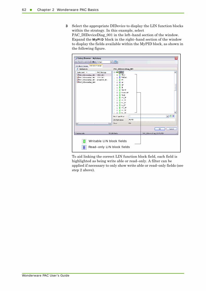
62 Chapter 2 Wonderware PAC Basics
Wonderware PAC User’s Guide
3 Select the appropriate DIDevice to display the LIN function blocks within the strategy. In this example, select PAC_DIDeviceDiag_001 in the left–hand section of the window. Expand the MyPID block in the right–hand section of the window to display the fields available within the MyPID block, as shown in the following figure.
To aid linking the correct LIN function block field, each field is highlighted as being write able or read–only. A filter can be applied if necessary to only show write able or read–only fields (see step 2 above).
Writable LIN block fields
Read–only LIN block fields
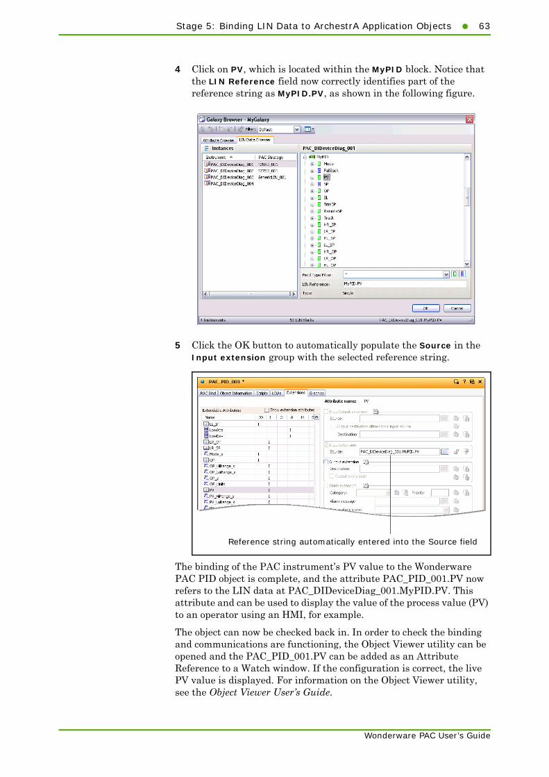
Stage 5: Binding LIN Data to ArchestrA Application Objects63
Wonderware PAC User’s Guide
4 Click on PV, which is located within the MyPID block. Notice that the LIN Reference field now correctly identifies part of the reference string as MyPID.PV, as shown in the following figure.
5 Click the OK button to automatically populate the Source in the Input extension group with the selected reference string.
The binding of the PAC instrument’s PV value to the Wonderware PAC PID object is complete, and the attribute PAC_PID_001.PV now refers to the LIN data at PAC_DIDeviceDiag_001.MyPID.PV. This attribute and can be used to display the value of the process value (PV) to an operator using an HMI, for example.
The object can now be checked back in. In order to check the binding and communications are functioning, the Object Viewer utility can be opened and the PAC_PID_001.PV can be added as an Attribute Reference to a Watch window. If the configuration is correct, the live PV value is displayed. For information on the Object Viewer utility, see the Object Viewer User’s Guide.
Reference string automatically entered into the Source field

64 Chapter 2 Wonderware PAC Basics
Wonderware PAC User’s Guide
Using the PAC Binding ToolThe PAC Binding tool provides an extremely efficient method of mapping LIN function blocks to Wonderware PAC objects, by automatically associating the correct fields for a given LIN function block to a Wonderware PAC object. The PAC Binding tool also provides support for exporting and importing binding configurations, which permits mass binding operations. The import facility is capable of creating instances of PAC instruments automatically, which allows automatic population of a Galaxy with a set of fully configured PAC instruments. Refer to "Overview" in Appendix B, "Advanced Binding Tool Operation," for further information regarding the more advanced features of the Binding Tool.
Note: This tool overwrites any previously defined manual binding on an object.
The PAC Binding tool is integrated into the ArchestrA IDE as a dockable extension view which can be displayed (if closed) by selecting PAC Binding within the View menu, or by clicking the PAC Binding toolbar icon. By default, the PAC Binding tool is docked on the right–hand side of the IDE. The location of the tool can be changed by dragging the extension to an alternative position. The following figure shows the two methods to show the PAC Binding tool. To hide the tool, click the x in the top–right corner of the PAC Binding tool window.
The PAC Binding tool has two tabs: Block Binding and Field Binding. The Block Binding tab allows the automatic creation of associations between an object and a LIN function block. The Field Binding tab presents view of the individual field bindings of the currently selected instance on the Block Binding tab (including those made manually — refer to "Manually Binding Objects" on page 56, and "Using the LIN Data Browser to Bind Objects" on page 58).
The Binding tool can be openedfrom the View menu...
.. or using the toolbarbutton.

Stage 5: Binding LIN Data to ArchestrA Application Objects65
Wonderware PAC User’s Guide
The following figure shows the Binding Tool with the Block Binding tab selected.
The toolbar is common to both the Block Binding tab and the Field Binding tab, and contains the following buttons:
• The Import and Export buttons allow the current binding configuration to be exported or imported from or into the Galaxy database, thus providing a means for rapid configuration. Refer to "Advanced Binding Tool Operation" on page 97 for further information.
• The Refresh drop-down menu button serves two purposes. It can refresh the instances list, or perform two types of validation on the bindings. The options under the Refresh button are:
• Refresh Instances list updates the tool with the currently available set of objects. This is necessary if PAC-based objects have been added, renamed or deleted from the Galaxy. The Refresh button can be used at any point, including during the initial loading of the tool so the user does not need to wait before creating and binding new instances.
• Validate LIN block bindings updates the validation status of the block bindings.
Import and Export configurationsRefresh button tomanually force thetool to refresh objectinformation orrevalidate bindings
Toolbar
List of availableobjects that theBinding tool canprocess. Anyalready–boundobjects areshown.
Check in automaticallychecked out objects
Displays a read–onlylist of bindings for thecurrently selectedinstance
Displays the objectsthat can be bound
LIN blockbindings stillbeing loaded bythe Binding Tool
Progress bar indicating remaining time until all LINblock bindings are loaded in the tool
Validation button

66 Chapter 2 Wonderware PAC Basics
Wonderware PAC User’s Guide
• Validate LIN Block and field bindings updates the validation status of the block bindings, and also the field bindings.
• The Check In button checks in all automatically–checked–out objects, that occurred during a binding operation. This allows multiple objects to be checked in at once.
• The Validation button displays the Block Binding Validation window, showing any validation issues with the binding data. The Validation button is only visible when there are validation issues.
When the tool first loads, a large amount of information concerning the bindings is loaded. During this process, a progress bar at the bottom of the window shows an estimated time to completion for this operation. For very large configurations, this can be several minutes. However, the loading of the binding information is performed as a background task, and operation of the tool (or any other feature within Wonderware PAC) can be used during this processing.
For information regarding the Block Binding tab, and how to use it to automatically bind objects, refer to the next section, "Block Binding tab" on page 66. For information regarding the Field Binding tab, refer to the section, "Field Binding tab" on page 70.
Block Binding tabIf the Block Binding tab is selected, the lower half of the PAC Binding tool window displays all the ApplicationObject instances eligible for binding. As the information shown in this tool requires the processing of a large amount of data from the Galaxy, there can be a short delay before all shown information can be edited. In this case, for each instance shown, Please Wait is shown in the LIN Block column until the data is editable. It is not necessary to wait for the tool to finish loading before continuing, however.
The data is presented in four columns, as described in the following table.
Column Description
Instance An ArchestrA object instance for which binding is possible.
Template The name of the template from which the instance was created.
Types The LIN function block types defined by the ApplicationObject template as suitable for binding. Information is taken from the template’s binding rules.
LIN Block Shows the LIN function block that has been mapped to the ArchestrA object. Refer to the table below for details.

Stage 5: Binding LIN Data to ArchestrA Application Objects67
Wonderware PAC User’s Guide
The value shown in the LIN Block column represents one of three states as described in the following table.
To automatically create a bind between an instance of an object and a LIN function block, the instance must be checked out for edit. The Binding Tool checks out any objects that are not already checked out by the user. Once the binding operation is complete, those automatically checked out can be checked back in by pressing the Check In button.
Note: If an object is already checked out by a different user, and the Binding Tool is used on that object, a message is displayed informing the user that the bind was not possible.
To automatically perform a binding operation
1 Ensure the Binding Tool is open, and select the object instance to be bound. Click anywhere in the LIN Block column on the appropriate object instance row. An ellipses button appears, as shown in the following figure.
LIN Block value Description
LIN block name, for example: "PAC_DIDeviceDiag_001.MyPID"
The name of the LIN function block that has been mapped to the object instance.
Please wait The information is being read from the Galaxy and not yet available for use within the PAC Binding tool. Wait for this message to disappear before attempting to perform any binding operation for this instance.
{blank} No binding has been created for this ArchestrA instance.
Click the ellipses button on the row of the instance to be bound

68 Chapter 2 Wonderware PAC Basics
Wonderware PAC User’s Guide
2 Click the ellipsis button on the row of the desired instance. The Browse for LIN blocks window opens, as shown in the following figure.
The left–hand side of the window shows the DIDevice instances (sorted alphabetically in ascending order, by default), together with any associated PAC strategy next to them. The right–hand side of the window shows the blocks within the associated PAC strategy, filtered to only show blocks of the suitable type(s) for the associated ApplicationObject.
Note: The same LIN function block may be selected for different ApplicationObject instances.
3 Select the desired DIDevice in the left–hand side of the window. In this example, PAC_DIDeviceDiag_001 has been selected.
4 In the right–hand side of the window, select the desired PID block. In this example, the MyPID block has been selected. The LIN Reference field and Type fields are change to reflect the selection. Alternatively, the block name can be typed manually in the LIN Reference field if it is known. As each part of the reference string is entered, the text is displayed in red until an exact match is found in the tree-view displayed in the right-hand window; at which point, the text turns black. When a period is entered, to continue refining the reference string, the tree view updates expanding the relevant section providing information on the available LIN fields.
PAC DIDevice instance ...
... and associated strategy configuration
Blocks withinthe strategyconfigurationthat are ofthe correcttype to bebound to theApplicationObject
Type ofblock
Referencefor selectedblock

Stage 5: Binding LIN Data to ArchestrA Application Objects69
Wonderware PAC User’s Guide
Note: The reference string is case-sensitive. If entering the reference string manually, be sure to observe the correct case.
5 Click the OK button to automatically bind the object. (Clicking Unbind removes any previously defined binding information from the Galaxy).
The PAC Binding tool now shows the appropriate object with the binding information, as shown in the following figure. Any unresolved LIN block references are displayed in red text in the LIN Block column. If validation errors are detected, the validation toolbar button appears which can be clicked for further information.
6 If the object was not checked out for edit before the binding process was performed, the PAC Binding tool checks the object out automatically. At this stage, the Check In button becomes available, and can be used to check in all the objects automatically checked out in one operation. Click the Check In button to automatically check these objects in.
... this LIN blockThis ApplicationObject is now bound to ...
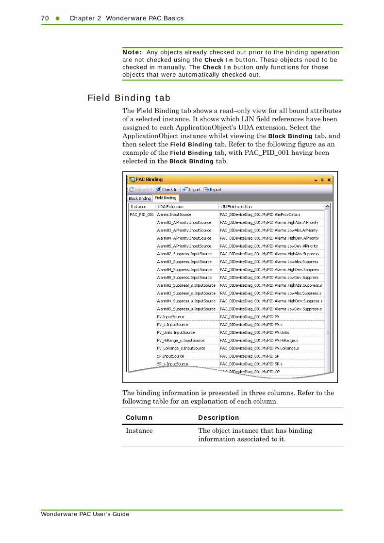
70 Chapter 2 Wonderware PAC Basics
Wonderware PAC User’s Guide
Note: Any objects already checked out prior to the binding operation are not checked using the Check In button. These objects need to be checked in manually. The Check In button only functions for those objects that were automatically checked out.
Field Binding tabThe Field Binding tab shows a read–only view for all bound attributes of a selected instance. It shows which LIN field references have been assigned to each ApplicationObject’s UDA extension. Select the ApplicationObject instance whilst viewing the Block Binding tab, and then select the Field Binding tab. Refer to the following figure as an example of the Field Binding tab, with PAC_PID_001 having been selected in the Block Binding tab.
The binding information is presented in three columns. Refer to the following table for an explanation of each column.
Column Description
Instance The object instance that has binding information associated to it.

Post–Configuration Procedure71
Wonderware PAC User’s Guide
The items in the UDA Extension column are a complete list of expected bindings. If no binding information is available against a single (or multiple) UDA Extensions, the associated LIN Field selection entry shows "---". Fields showing "---" can be indicative of incorrect or incomplete binding. This may occur if only manual binding has been performed on a subset of available UDA extensions, or the tool has been upgraded since the binding was last set and addition attributes that can be bound are available.
Post–Configuration ProcedureHaving completed stages 1 to 5, the Foxboro PAC instrument exposes its runtime values to the ArchestrA environment. Other LIN–based instruments can now be set up in a similar manner, or InTouch can be used to build pages in order to visualise and control the instruments.
Wonderware PAC DINetworks and DIDevices are deployed in the usual manner as with all other ArchestrA objects. Initial deployment of a DINetwork can take some time, whilst the DAServer is installed and configured on the remote node. Once a DINetwork has been deployed, the DAServer runs in demo mode if no license is found. The demo mode functions for 120 minutes allowing time to check the configuration, before having to undeploy and redeploy the DINetwork to restart the server.
After deployment of a DINetwork or DIDevice, it is recommended that the Object Viewer, launched from within the IDE, is used to test communication between the LIN instrument and ArchestrA. Checking that the instrument can communicate (in both directions) at this stage can be helpful in diagnosing any subsequent communication issues. If communication issues do occur after deployment, it is recommended that the steps in Appendix E, "Troubleshooting Communication Errors," are followed before contacting the various support routes.
UDA Extension The User Defined Attribute (UDA) reference for the specified instance.
LIN Field selection The block and field in the LIN instrument that the UDA extension of the instance maps to. Clicking the ellipsis button on the LIN Field selection column displays the LIN Data Browser window, allowing individual block fields to be browsed to and edited.
Column Description

72 Chapter 2 Wonderware PAC Basics
Wonderware PAC User’s Guide
Using Store and ForwardIf Store and Forward is configured (the Foxboro PAC instrument strategy has Recording Groups defined, and the History Extension is enabled for ArchestrA objects), the Store and Forward tool can be used to avoid gaps in Historian data if the communication between the LIN instrument and ArchestrA ever fails.
The Store and Forward tool automatically attempts to fill in gaps in Historian that may exist, typically created when the data flow from a Foxboro PAC instrument to ArchestrA is interrupted. The Store and Forward tool examines .uhh files FTP’d from Foxboro PAC instruments, and compares the contents of these files against the data held in Historian. Where possible, Store and Forward then attempts to fill in the gaps if the data is available in the .uhh files.
Alarm events for function blocks within a Foxboro PAC strategy can also be forwarded to the Wonderware Alarm Database for the associated area.
For this mechanism to work, there needs to be a mapping of LIN fields to Historian tags and LIN Recording Groups to ArchestrA Areas for the Wonderware Alarm Database. Store and Forward uses a .usf configuration file that provides this mapping information. The Configure UStoreForward tool, accessed from the Wonderware PAC toolbar, automatically creates this .usf file by examining the fields that are in a Recording Group within a Foxboro PAC instrument strategy and maps these against the ArchestrA objects that have the History Extension enabled.
For information on how to automatically create the Store and Forward mapping configuration file using the Configure UStoreForward button on the Wonderware PAC toolbar, refer to "Configuring Store and Forward" on page 105. For a detailed explanation on how to use and configure Store and Forward, refer to the Foxboro PAC Store and Forward User’s Guide (HA030835).
Improving Productivity with the PAC Binding Tool
The PAC Binding tool has the ability to import and export binding data. This allows a user to save a current configuration to a comma separated values (csv) file. This can be used to import into a different Galaxy, or used as a template and then modified before subsequently reimporting it.
The import function automatically creates instances of objects listed in the csv file. Any instance listed in the file that already exists in the Galaxy are overwritten provided they are not currently checked out.
The import function discreetly validates the name of the DIDevice object in each specified block binding and whether the LIN block exists in the namespace of a PAC Strategy object associated with that DIDevice object. Any validation errors are logged and made available afterwards.

Improving Productivity with the PAC Binding Tool73
Wonderware PAC User’s Guide
The advantage of the import/export feature is that the user can populate a Galaxy with a set of bound ApplicationObject instances having created a csv configuration file.
Refer to "Advanced Binding Tool Operation" on page 97 for full information on using these advanced features of the PAC Binding tool.

74 Chapter 2 Wonderware PAC Basics
Wonderware PAC User’s Guide

75
Wonderware PAC User’s Guide
Chapter 3
Instrument Diagnostics
This chapter provides information on obtaining diagnostic information from a Foxboro PAC instrument using the $PAC_DIDeviceDiag object.
This chapter has the following sections:
• Overview
• Operator Interface
• Configuration
• Working with Redundancy
• Symbol Parameters and PAC Device Field references
OverviewA DINetwork instance (a PAC DAServer) provides the interface between the LIN network and the Galaxy. It is necessary to assign the physical instruments (DIDevices) to the DINetwork instance. This ensures the PAC DAServer is able to communicate with the PAC instruments (and any generic LIN devices).
PAC DIDevice objects provide the mechanism for a DINetwork to communicate with the LIN device. Each DIDevice instance is associated with an instrument configuration strategy, found in the PAC Strategies tab.

76 Chapter 3 Instrument Diagnostics
Wonderware PAC User’s Guide
Foxboro PAC instruments (T2550 and T2750) can provide diagnostic information and present this to the operator through the HMI. The $PAC_DIDeviceDiag application object provides this functionality, and offers graphic symbols to give a clear indication of the nature and detail of any fault conditions should they arise. In addition to fault conditions, the symbols also allow the condition of the I/O modules, the strategy running on the PAC device, communication and time settings to be monitored. The $PAC_DIDeviceDiag object is an extension to the $PAC_DIDevice object (which can be used for non-T2550/T2750 instruments).
The diagnostic symbol relies on specific LIN function blocks within the strategy. The required LIN function blocks are automatically added to a blank strategy when a T2550 or T2750 instrument strategy is created through the IDE. If existing T2550 or T2750 strategies are imported into Wonderware PAC, care must be taken to ensure the required LIN function blocks are also created, and appropriate alarms enabled.
Legacy devices, or Generic LIN devices which do not support the use of the following LIN function blocks cannot use the diagnostic capability of the $PAC_DIDeviceDiag, and should instead use a $PAC_DIDevice object which provides support for the LIN device, but without the diagnostics capability.
• TACTICIAN
• EIO_DIAG
• DB_DIAG
• IDENTITY
• TOD_DIAG
• ELINDIAG
• RED_CTRL
Note: If more than one block of the above types is running in the PAC device, then it cannot be defined which block will be used.
In addition to the above LIN function blocks, various alarm fields must also be enabled in the TACTICIAN and EIO_DIAG blocks. If the Wonderware PAC strategies were created through the IDE, these alarms are already enabled by default. Refer to "Symbol Parameters and PAC Device Field references" on page 88 for details of which alarms need to be enabled.
Full support for redundant configurations is provided. Refer to "Working with Redundancy" on page 88 for details on how to configure the $PAC_DIDeviceDiag object for use in redundant systems.
Operator InterfaceTwo primary views are offered for the diagnostics symbol:

Operator Interface77
Wonderware PAC User’s Guide
• An graphical overview of the health of the Foxboro PAC instrument, for general use, including the use of a traffic light display to represent the health of the instrument.
• A detailed view, which contains more specific status information and the ability to control the instrument where it is configured to run in duplex mode.
Overview DisplayThe overview display indicates fault conditions through the use of a traffic light system as follows:
Traffic Light Description
Red. When illuminated, indicates a major fault. Failure in any of the following areas are classified as major faults:
• block RAM checksum
• hardware fault
• block software fault
• I/O block RAM checksum
• primary processor fault
• secondary processor fault
• battery failure
• real-time clock status
• brown out
• power failure
• temporary power failure
• device communications
• strategy communications
• primary synchronisation status

78 Chapter 3 Instrument Diagnostics
Wonderware PAC User’s Guide
Refer to "Symbol Parameters and PAC Device Field references" on page 88, for additional information on the alarm conditions that trigger the major and minor fault conditions.
The overview symbol also shows the hardware configuration of the Wonderware PAC device, showing the configuration (simplex or duplex processors), and the I/O modules assigned to the various slots (sites). If an issue is identified on one of the I/O modules, a red border is displayed around the faulty module. The object name is also shown on the symbol to enable identification of the device.
There are two properties that can be configured to influence the overview symbol display:
• BaseSize allows the view to be set to correspond to the number of I/O sites available. Allowed values are 0, 4, 8 and 16. The default default value is 8.
• ShowDetail determines whether details are shown on the symbol (normally set to TRUE), or should be hidden (FALSE). Hiding the symbol details can enhance the appearance of the symbol when shrunk to a small size.
Click anywhere on the overview symbol to display the detailed symbol window, which provides additional information on the status of the instrument, including any faults.
Example Overview Display – No FaultsThe following figure shows the $PAC_DIDeviceDiag overview symbol in the following configuration:
• A BaseSize set to 8 sites
• ShowDetail set to TRUE
• Two-processor duplex configuration
Amber. When illuminated, indicates a minor fault. Failure in any of the following areas are classified as minor faults:
• battery low
• primary license failure
• secondary license failure
Green. When illuminated, the health of the Foxboro PAC instrument is good (no major or minor faults detected).
Traffic Light Description

Operator Interface79
Wonderware PAC User’s Guide
• No faults reported
As there are no faults, and everything is reported as healthy, the traffic light symbol on the left illuminates green.
Example Overview Display – Faulty ModulesThe following figure shows a $PAC_DIDeviceDiag overview symbol in a major fault condition. The configuration of the Foxboro PAC instrument is as follows:
• A BaseSize set to 8 sites
• ShowDetail set to TRUE
• Two-processor duplex configuration

80 Chapter 3 Instrument Diagnostics
Wonderware PAC User’s Guide
• A module fault being shown for the modules at site one and site three, causing the symbol to report a major fault. This would be the case where the expected module does not match that fitted, or when the primary (or secondary in duplex operation) does not report a healthy status for the site exhibiting a faulty condition. Any sites that do not have a module fitted (not shown in this example), are shown as empty.
Example Overview Display – Communications FaultThe following figure shows a $PAC_DIDeviceDiag overview symbol experiencing a communications fault. The configuration of the instrument is as follows:
• A BaseSize set to 8 sites
• ShowDetail set to TRUE
• Two-processor duplex operation
• A communications fault, represented by the large red X’s underneath the processors. The fault is reported when the Online attribute is FALSE. The number of processors shown will always reflect the setting of the Simplex symbol property.

Operator Interface81
Wonderware PAC User’s Guide
Note: Without healthy communications to the device, it is not possible to determine what hardware is fitted in each site, so empty sites are displayed until communication is restored.
Example Overview Display – Multiple InstrumentsThe following figure shows two Foxboro PAC instruments, shrunk in size to fit side-by-side on the HMI. The configuration of the instruments is as follows:
• A BaseSize set to 16 sites
• ShowDetail set to FALSE (making the symbol clearer when reduced in size)
• Single processor, simplex operation
• Empty sites shown in both of the Foxboro PAC instruments (four spare sites on one; six empty sites on the other).
• No faults reported

82 Chapter 3 Instrument Diagnostics
Wonderware PAC User’s Guide
Detailed DisplayThe detailed view symbol is displayed when the overview symbol is clicked. The detailed view contains a set of tabs categorising the information available. These categories are:
If a major or minor fault condition is present, then the corresponding indicator light on the appropriate tab is illuminated.
An example of the Major Faults tab is shown in the following figure. The status for all criteria which constitutes a major fault are shown, and are updated in real-time. Any field which is in alarm is highlighted in red.
Note: Seconday-processor related information is hidden when the object’s Simplex attribute is set to TRUE.
Major faultconditions beingmonitored and thecurrent status
Minor fault conditions beingmonitored and the current status
Modules configured in the strategy andthose actually fitted to the instrument.
Current time anddate in the device,and associatedsettings
Communication configuration ofthe instrument, including the instrument’s IP address and LINnode address
Information related to the loaded strategyand the synchronisation state. Control ofduplex operation can be performed here.
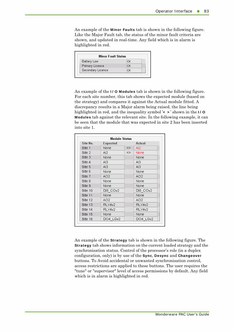
Operator Interface83
Wonderware PAC User’s Guide
An example of the Minor Faults tab is shown in the following figure. Like the Major Fault tab, the status of the minor fault criteria are shown, and updated in real-time. Any field which is in alarm is highlighted in red.
An example of the I/O Modules tab is shown in the following figure. For each site number, this tab shows the expected module (based on the strategy) and compares it against the Actual module fitted. A discrepancy results in a Major alarm being raised, the line being highlighted in red, and the inequality symbol ’< >’ shown in the I/O Modules tab against the relevant site. In the following example, it can be seen that the module that was expected in site 2 has been inserted into site 1.
An example of the Strategy tab is shown in the following figure. The Strategy tab shows information on the current loaded strategy and the synchronisation status. Control of the processor’s role (in a duplex configuration, only) is by use of the Sync, Desync and Changeover buttons. To Avoid accidental or unwanted synchronisation control, access restrictions are applied to these buttons. The user requires the "tune" or "supervisor" level of access permissions by default. Any field which is in alarm is highlighted in red.
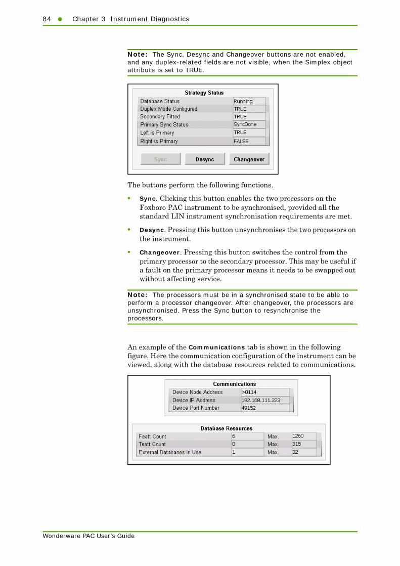
84 Chapter 3 Instrument Diagnostics
Wonderware PAC User’s Guide
Note: The Sync, Desync and Changeover buttons are not enabled, and any duplex-related fields are not visible, when the Simplex object attribute is set to TRUE.
The buttons perform the following functions.
• Sync. Clicking this button enables the two processors on the Foxboro PAC instrument to be synchronised, provided all the standard LIN instrument synchronisation requirements are met.
• Desync. Pressing this button unsynchronises the two processors on the instrument.
• Changeover. Pressing this button switches the control from the primary processor to the secondary processor. This may be useful if a fault on the primary processor means it needs to be swapped out without affecting service.
Note: The processors must be in a synchronised state to be able to perform a processor changeover. After changeover, the processors are unsynchronised. Press the Sync button to resynchronise the processors.
An example of the Communications tab is shown in the following figure. Here the communication configuration of the instrument can be viewed, along with the database resources related to communications.

Configuration85
Wonderware PAC User’s Guide
An example of the Time tab is shown in the following figure. The Time tab shows the instrument’s current date and time, along with the time configuration mode.
Standard ArchestrA icons are used for the data quality status for each of the parameters in the detailed view symbol tabs. These can be changed for a Galaxy from within the ArchestrA IDE (see ArchestrA IDE help topic for "Setting the Appearance of a Status Element"). By default, the icons used are shown in the following table:
ConfigurationThe PAC_DIDeviceDiag is configured using the Object Editor like other standard ArchestrA objects. The symbol also has two attributes that need to be set prior to deployment.
Note: Before configuring a PAC_DIDeviceDiag, be sure that the Instrument Configuration instance that the PAC_DIDeviceDiag represents has been created; it need not be fully configured, but the instance should exist.
To configure a PAC_DIDeviceDiag:
1 Open the PAC_DIDeviceDiag object in the Object Editor by double clicking on the DINetwork instance. The Object Editor opens with the General tab displayed.

86 Chapter 3 Instrument Diagnostics
Wonderware PAC User’s Guide
2 From the drop-down list under the Configuration Object field, select an Instrument Configuration previously defined which matches the strategy stored within the LIN instrument, as shown in the following figure.
3 Select the UDAs tab and locate and select the Simplex [$PAC_DIDeviceDiag] entry in the Inherited UDAs section.
4 Locate the True/False checkbox in the Value section, and tick appropriately depending on whether the Foxboro PAC Instrument has a single processor (ticked), or a duplex processor (unticked).
5 Close the object and save the changes. The object is now ready for deployment.
Select the Simplex UDA ...
... and tick the checkbox according to whether the instrument is operating in a simplex mode (ticked) or a duplex mode (unticked).
UDAs tab selected

Configuration87
Wonderware PAC User’s Guide
Once the above procedure is complete, the diagnostic symbol can access data from a range of device function blocks without any need to setup further references. However, two symbol attributes need to be configured during commissioning that are contained within the overview symbol itself. These attributes control the overview display as described in the following table.
When placing the symbol on a page within InTouch WindowMaker, double-click on the symbol to display the Custom Properties window, an example of which is shown in the following figure.
Edit the two custom properties as appropriate.
Symbol attribute description
BaseSize An integer value dictating how many I/O sites are shown when the overview symbol is displayed. This should be set to correspond to the number of physical I/O sites. Valid values are 0, 4, 8 and 16. The default is 8.
ShowDetail A boolean attribute that allows better display of the overview symbol when it is resized to very small. The default value is TRUE, allowing detail to be shown in the symbol.
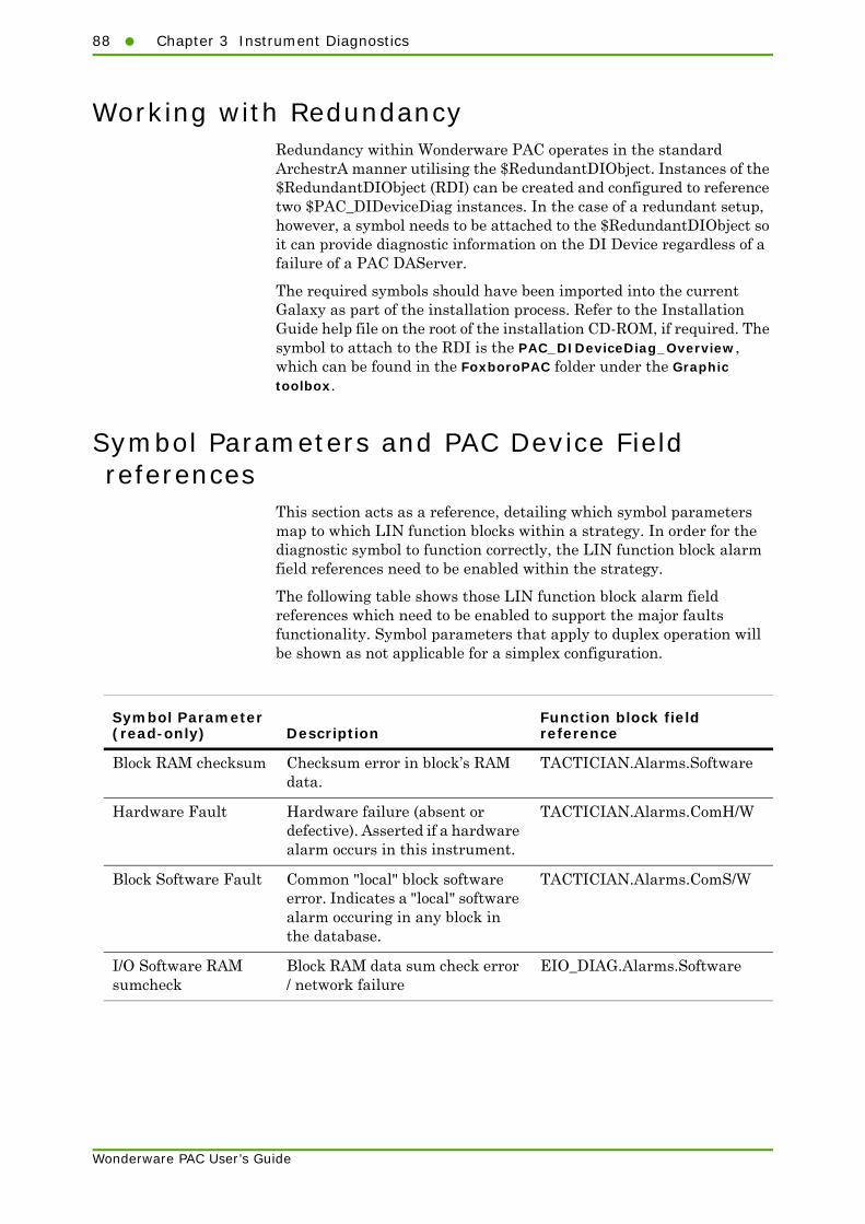
88 Chapter 3 Instrument Diagnostics
Wonderware PAC User’s Guide
Working with RedundancyRedundancy within Wonderware PAC operates in the standard ArchestrA manner utilising the $RedundantDIObject. Instances of the $RedundantDIObject (RDI) can be created and configured to reference two $PAC_DIDeviceDiag instances. In the case of a redundant setup, however, a symbol needs to be attached to the $RedundantDIObject so it can provide diagnostic information on the DI Device regardless of a failure of a PAC DAServer.
The required symbols should have been imported into the current Galaxy as part of the installation process. Refer to the Installation Guide help file on the root of the installation CD-ROM, if required. The symbol to attach to the RDI is the PAC_DIDeviceDiag_Overview, which can be found in the FoxboroPAC folder under the Graphic toolbox.
Symbol Parameters and PAC Device Field references
This section acts as a reference, detailing which symbol parameters map to which LIN function blocks within a strategy. In order for the diagnostic symbol to function correctly, the LIN function block alarm field references need to be enabled within the strategy.
The following table shows those LIN function block alarm field references which need to be enabled to support the major faults functionality. Symbol parameters that apply to duplex operation will be shown as not applicable for a simplex configuration.
Symbol Parameter (read-only) Description
Function block field reference
Block RAM checksum Checksum error in block’s RAM data.
TACTICIAN.Alarms.Software
Hardware Fault Hardware failure (absent or defective). Asserted if a hardware alarm occurs in this instrument.
TACTICIAN.Alarms.ComH/W
Block Software Fault Common "local" block software error. Indicates a "local" software alarm occuring in any block in the database.
TACTICIAN.Alarms.ComS/W
I/O Software RAM sumcheck
Block RAM data sum check error / network failure
EIO_DIAG.Alarms.Software
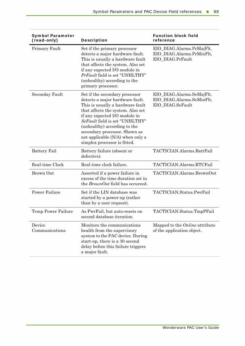
Symbol Parameters and PAC Device Field references89
Wonderware PAC User’s Guide
Primary Fault Set if the primary processor detects a major hardware fault. This is usually a hardware fault that affects the system. Also set if any expected I/O module in PrFault field is set "UNHLTHY" (unhealthy) according to the primary processor.
EIO_DIAG.Alarms.PrMajFlt, EIO_DIAG.Alarms.PrMinFlt, EIO_DIAG.PrFault
Seconday Fault Set if the secondary processor detects a major hardware fault. This is usually a hardware fault that affects the system. Also set if any expected I/O module in SeFault field is set "UNHLTHY" (unhealthy) according to the secondary processor. Shown as not applicable (N/A) when only a simplex processor is fitted.
EIO_DIAG.Alarms.SeMajFlt, EIO_DIAG.Alarms.SeMinFlt, EIO_DIAG.SeFault
Battery Fail Battery failure (absent or defective).
TACTICIAN.Alarms.BattFail
Real-time Clock Real-time clock failure. TACTICIAN.Alarms.RTCFail
Brown Out Asserted if a power failure in excess of the time duration set in the BrownOut field has occureed.
TACTICIAN.Alarms.BrownOut
Power Failure Set if the LIN database was started by a power-up (rather than by a user request).
TACTICIAN.Status.PwrFail
Temp Power Failure As PwrFail, but auto-resets on second database iteration.
TACTICIAN.Status.TmpPFail
Device Communications
Monitors the communications health from the supervisory system to the PAC device. During start-up, there is a 30 second delay before this failure triggers a major fault.
Mapped to the Online attribute of the application object.
Symbol Parameter (read-only) Description
Function block field reference

90 Chapter 3 Instrument Diagnostics
Wonderware PAC User’s Guide
Primary Fault Set if the primary processor detects a major hardware fault. This is usually a hardware fault that affects the system. Also set if any expected I/O module in PrFault field is set "UNHLTHY" (unhealthy) according to the primary processor.
EIO_DIAG.Alarms.PrMajFlt, EIO_DIAG.Alarms.PrMinFlt, EIO_DIAG.PrFault
Seconday Fault Set if the secondary processor detects a major hardware fault. This is usually a hardware fault that affects the system. Also set if any expected I/O module in SeFault field is set "UNHLTHY" (unhealthy) according to the secondary processor. Shown as not applicable (N/A) when only a simplex processor is fitted.
EIO_DIAG.Alarms.SeMajFlt, EIO_DIAG.Alarms.SeMinFlt, EIO_DIAG.SeFault
Battery Fail Battery failure (absent or defective).
TACTICIAN.Alarms.BattFail
Real-time Clock Real-time clock failure. TACTICIAN.Alarms.RTCFail
Brown Out Asserted if a power failure in excess of the time duration set in the BrownOut field has occureed.
TACTICIAN.Alarms.BrownOut
Power Failure Set if the LIN database was started by a power-up (rather than by a user request).
TACTICIAN.Status.PwrFail
Temp Power Failure As PwrFail, but auto-resets on second database iteration.
TACTICIAN.Status.TmpPFail
Device Communications
Monitors the communications health from the supervisory system to the PAC device. During start-up, there is a 30 second delay before this failure triggers a major fault.
Mapped to the Online attribute of the application object.
Symbol Parameter (read-only) Description
Function block field reference
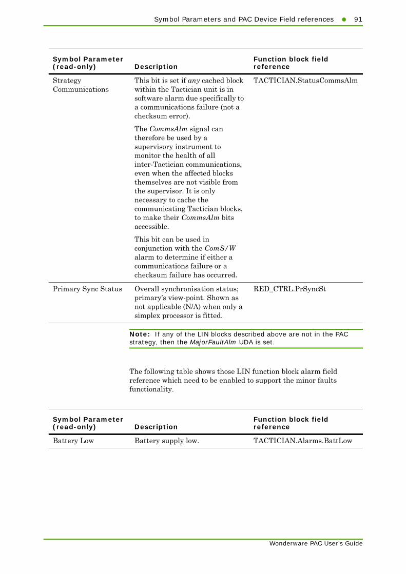
Symbol Parameters and PAC Device Field references91
Wonderware PAC User’s Guide
Note: If any of the LIN blocks described above are not in the PAC strategy, then the MajorFaultAlm UDA is set.
The following table shows those LIN function block alarm field reference which need to be enabled to support the minor faults functionality.
Strategy Communications
This bit is set if any cached block within the Tactician unit is in software alarm due specifically to a communications failure (not a checksum error).
The CommsAlm signal can therefore be used by a supervisory instrument to monitor the health of all inter-Tactician communications, even when the affected blocks themselves are not visible from the supervisor. It is only necessary to cache the communicating Tactician blocks, to make their CommsAlm bits accessible.
This bit can be used in conjunction with the ComS/W alarm to determine if either a communications failure or a checksum failure has occurred.
TACTICIAN.StatusCommsAlm
Primary Sync Status Overall synchronisation status; primary’s view-point. Shown as not applicable (N/A) when only a simplex processor is fitted.
RED_CTRL.PrSyncSt
Symbol Parameter (read-only) Description
Function block field reference
Symbol Parameter (read-only) Description
Function block field reference
Battery Low Battery supply low. TACTICIAN.Alarms.BattLow

92 Chapter 3 Instrument Diagnostics
Wonderware PAC User’s Guide
Note: If any of the LIN blocks described above are not in the PAC strategy, then the MinorFaultAlm UDA is set.
Run-time attributes for the other detailed view symbol fields can be found in the online help within the Wonderware PAC IDE for the $PAC_DIDeviceDiag object.
Primary Licence Primary licence exceeded. TACTICIAN.Alarms.PLicence
Seconday Licence (Redunant system only). Asserted if the current configuration exceeds the licence levels of this product on the seconday unit in a 2-processor redundant system. Shown as not applicable (N/A) when only a simplex processor is fitted.
TACTICIAN.Alarms.SLicence
Symbol Parameter (read-only) Description
Function block field reference

93
Appendix A
Licensing
This appendix provides information on the licensing system used in Wonderware PAC.
OverviewThe PAC DAServer requires a license in order to operate. A license is required for each machine hosting an instance of a DINetwork.
The Wonderware PAC system uses the same style of license as the System Platform, and the process to install and maintain licenses is the same.
To install a license, the System Platform License Utility is used. Follow the procedure below to install a license.
To install a license
1 Launch the License Utility from the Start menu by selecting Start > All Programs > Wonderware > Common > License Utility.
2 Select Install License File from the File menu.
3 Navigate to the CD-ROM drive that contains the Wonderware PAC software and license, and open the license file (the filename is wwsuite.lic).
4 Confirm the defaults shown in the Destination Computer for Installation dialogue window, and click OK.
5 When the Installing a license file dialogue window appears, ensure the Add button is pressed. Do not select the Overwrite option.
Note: Depending on your geographic location, a USB dongle may also be required to license the software.
Wonderware PAC User’s Guide
94 Appendix A Licensing
If no valid license is found at startup, the Wonderware PAC DAServer runs in a special demonstration mode for 120 minutes, during which time full functionality is provided. After the 120 minutes has lapsed, the PAC DAServer enters a limited functionality state in which:
• The system item $sys$Licensed it set to FALSE
• Tag updates are disabled
• Tag writing is disabled
• All items have BAD quality status
• No new items are accepted
If a valid license is detected at any point during the demonstration or limited functionality mode, full functionality is restored and an entry is written to the logger. The check for a valid license is performed every 30 seconds during the demonstration and limited functionality modes, and each time no license is found, an entry is written to the logger.
If a valid license is found, but then subsequently removed, the PAC DAServer continues to operate and provide valid data. This allows for instances where the licensing server falls over, but without interrupting the runtime operation of Wonderware PAC. In this instance, $sys$Licensed remains set to TRUE. The check for a valid license will be next initiated at the next startup.
System items, such as the $sys$Licensed attribute are added at the DINetwork level (for example, PAC_DINetwork_001.$sys$Licensed), whereas LIN data is available at the DIDevice level. The $sys$Licensed attribute is displayed on the DINetwork diagnostic symbol, providing the operator with license confirmation on an HMI.
Wonderware PAC User’s Guide

Overview95
The figure below shows the license detection sequence.
DA Server starts
License exists?
Run in demonstration
mode.Licensed.
License found?
Running time <120 mins?
Pause 30 seconds
No
No
Yes
Run in limited functionality mode.
Unlicensed.
No
Run in licensed mode
Yes
Yes
Wonderware PAC User’s Guide

96 Appendix A Licensing
Wonderware PAC User’s Guide

97
Wonderware PAC User’s Guide
Appendix B
Advanced Binding ToolOperation
This appendix provides information on the more advanced capabilities of the PAC Binding tool. In particular, it discusses the import and export capabilities.
This chapter contains the following sections:
• Overview
• Exporting Binding Configuration
• Manipulating Binding Configuration
• Importing Binding Configuration
• Validation
OverviewThe PAC Binding tool allows the current binding configuration to be exported to a comma separated value (csv) file, which can be subsequently edited in any text editor, or in other csv-compatible readers (such as Microsoft Excel™).
Once exported, the configuration can be edited and duplicated so as to enable a quick and efficient method to import large and complex configurations. Using an appropriate editor, the configuration file can be used to quickly define the mappings between ApplicationObjects and LIN blocks, which when reimported into the Galaxy, can be automatically instantiated and bound.
During an import operation, new instances are created and bound using the information specified in the imported file. Block bindings on pre-existing objects are overwritten if those instances are not checked out.
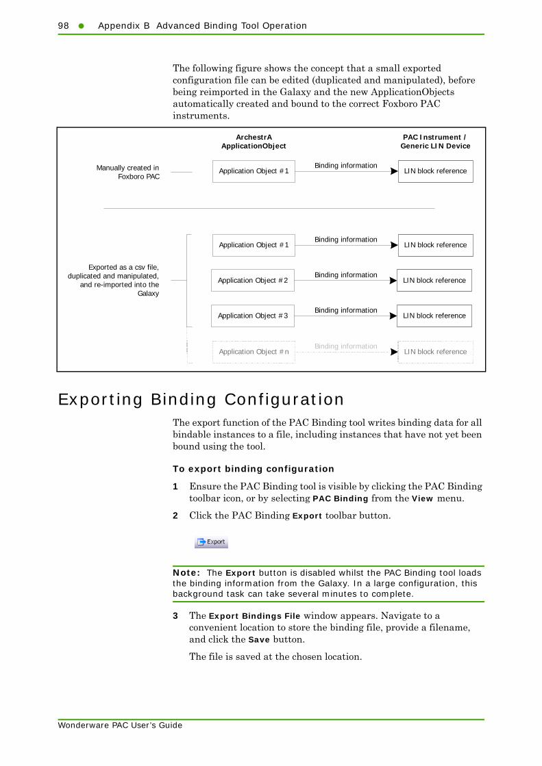
98 Appendix B Advanced Binding Tool Operation
Wonderware PAC User’s Guide
The following figure shows the concept that a small exported configuration file can be edited (duplicated and manipulated), before being reimported in the Galaxy and the new ApplicationObjects automatically created and bound to the correct Foxboro PAC instruments.
Exporting Binding ConfigurationThe export function of the PAC Binding tool writes binding data for all bindable instances to a file, including instances that have not yet been bound using the tool.
To export binding configuration
1 Ensure the PAC Binding tool is visible by clicking the PAC Binding toolbar icon, or by selecting PAC Binding from the View menu.
2 Click the PAC Binding Export toolbar button.
Note: The Export button is disabled whilst the PAC Binding tool loads the binding information from the Galaxy. In a large configuration, this background task can take several minutes to complete.
3 The Export Bindings File window appears. Navigate to a convenient location to store the binding file, provide a filename, and click the Save button.
The file is saved at the chosen location.
Application Object #1 LIN block reference
ArchestrA ApplicationObject
PAC Instrument / Generic LIN Device
Manually created inFoxboro PAC
Application Object #1 LIN block reference
Application Object #2 LIN block reference
Application Object #3 LIN block reference
Application Object #n LIN block reference
Exported as a csv file, duplicated and manipulated,
and re-imported into the Galaxy
Binding information
Binding information
Binding information
Binding information
Binding information

Manipulating Binding Configuration99
Wonderware PAC User’s Guide
Note: The export function only saves block binding information. It does not save the individual field mappings that may have manually been created by the user.
Manipulating Binding ConfigurationTo manipulate the binding configuration using the exported PAC Binding data, an editor which supports the import of csv files is required. Most text editors can open csv files, or a spreadsheet program such as Microsoft Excel can be used.
The format of the exported binding file is shown in the following figure. A separate line is created in the exported file for each instance of a bindable object.
If an ApplicationObject is bound to multiple LIN blocks, then the last two fields (Block n and Type) are repeated as many times as necessary. The ApplicationObject configuration is regarded as complete when the line ends.
The following table describes the individual fields in more detail.
Field Description
Instance The ArchestrA object instance that was created from a Wonderware PAC template and can be bound to a LIN block.
Template The Wonderware PAC template that was used to create the instance. Based on this field, the appropriate predefined set of LIN blocks can be written to the instance’s attributes.
Instance Template Block 1 Type Block 2 Type Block 3 Type
Repeated as many timesas necessary
Optional: only included if aninstance is bound to more thanone LIN block
ArchestrA object
Object template
Ref of LIN block
The type of block thathas, or could be bound

100 Appendix B Advanced Binding Tool Operation
Wonderware PAC User’s Guide
Adding a Binding EntryFor a basic setup, the following is an example exported binding configuration file:
The first line is a header line, and is not part of the configuration. The line can be deleted, but it is recommended it remains as a guide to the field contents. It is especially useful when the file is viewed as a spreadsheet.
The second line indicates the following:
• The object instance is called PAC_PID_001
• The object instance was created from a template called $PAC_PID
• The object is already bound to a LIN block called MyPID, with a reference string of PAC_DIDevice_001.MyPID
• The binding is of the PID, PID_CONN, or PID_LINK type. Square brackets must be included around the type field where more than one entry is listed, separated by commas.
Block 1 The reference string of the LIN block, if bound.
If this field is blank, the instance has not been bound to any LIN block. The type(s) of block that the object could be bound to is shown in the Type field during export (though this is optional).
Type A list of LIN block types that are compatible with the instance’s template ($PAC_PID can bind to three types of LIN block for example: PID, PID_CONN, and PID_LINK).
If there are more than one bindable LIN block types, then they must be grouped using square brackets [ ]. All exported Type fields have square brackets, regardless of the number of bindable LIN block types.
The field is information–only; no processing is performed based on the contents of this field. The field is written to the exported file for documentation completeness.
For importing purposes, this field can be left blank if desired.
Field Description
Instance,Template,Block 1,Type,Block n,TypePAC_PID_001,$PAC_PID,PAC_DIDevice_001.MyPID,[PID,PID_CONN,PID_LINK]
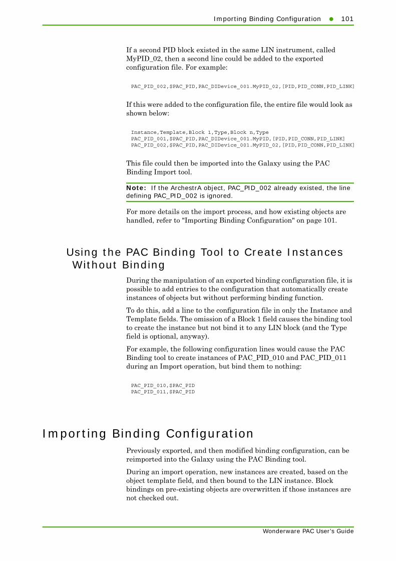
Importing Binding Configuration101
Wonderware PAC User’s Guide
If a second PID block existed in the same LIN instrument, called MyPID_02, then a second line could be added to the exported configuration file. For example:
If this were added to the configuration file, the entire file would look as shown below:
This file could then be imported into the Galaxy using the PAC Binding Import tool.
Note: If the ArchestrA object, PAC_PID_002 already existed, the line defining PAC_PID_002 is ignored.
For more details on the import process, and how existing objects are handled, refer to "Importing Binding Configuration" on page 101.
Using the PAC Binding Tool to Create Instances Without Binding
During the manipulation of an exported binding configuration file, it is possible to add entries to the configuration that automatically create instances of objects but without performing binding function.
To do this, add a line to the configuration file in only the Instance and Template fields. The omission of a Block 1 field causes the binding tool to create the instance but not bind it to any LIN block (and the Type field is optional, anyway).
For example, the following configuration lines would cause the PAC Binding tool to create instances of PAC_PID_010 and PAC_PID_011 during an Import operation, but bind them to nothing:
Importing Binding ConfigurationPreviously exported, and then modified binding configuration, can be reimported into the Galaxy using the PAC Binding tool.
During an import operation, new instances are created, based on the object template field, and then bound to the LIN instance. Block bindings on pre-existing objects are overwritten if those instances are not checked out.
PAC_PID_002,$PAC_PID,PAC_DIDevice_001.MyPID_02,[PID,PID_CONN,PID_LINK]
Instance,Template,Block 1,Type,Block n,TypePAC_PID_001,$PAC_PID,PAC_DIDevice_001.MyPID,[PID,PID_CONN,PID_LINK]PAC_PID_002,$PAC_PID,PAC_DIDevice_001.MyPID_02,[PID,PID_CONN,PID_LINK]
PAC_PID_010,$PAC_PIDPAC_PID_011,$PAC_PID

102 Appendix B Advanced Binding Tool Operation
Wonderware PAC User’s Guide
To import binding configuration data
1 Ensure the PAC Binding tool is visible by clicking the PAC Binding toolbar icon, or by selecting PAC Binding from the View menu.
2 Click the PAC Binding Import toolbar button.
3 The Import Bindings File window appears. Locate the binding file, select it, and click the Open button.
4 The Importing PAC Instances window appears, and provides an indication as to the status of the import operation. An example is shown in the following figure.
5 After the binding operation is complete, new objects need to be checked in. This is an automatic operation, but if enabled in the User Information configuration window, a comment can be set for the check in operation.
The import operation completes. When the Importing PAC Instances window is closed, the PAC Binding tool refreshes to show all the known bindings in the galaxy.
Existing objectsare skipped.
New objects areautomaticallycreated...
... and thenautomatically bound.

Validation103
Wonderware PAC User’s Guide
Following the import function, a validation routine runs to highlight any unresolved LIN block references. If at least one validation issue exist, the Block Binding Validation window appears to explain each issue. These should not be regarded as errors; instead the content highlights those DIDevices, PAC strategy instances or LIN blocks that are incomplete at this stage. For more information on validation, refer to "Validation" on page 103.
Note: Depending on the number of lines in the import file, the import operation can take considerable time to complete. A very large file can take over an hour for example. The operation can be cancelled at any time.
ValidationThe import function (see "Importing Binding Configuration" on page 101) allows the user to populate the Galaxy with a set of bound ApplicationObject instances with a .csv file which has been manually edited. At the stage of importing, none of the specified DIDevice instances, associated PAC Strategy instances or actual LIN blocks need exist. This allows the user the import the configuration and then develop the DIDevice instances and instrument strategies afterwards.
Having potentially imported User-Defined Attributes with missing LIN references, the validation function detects and then alerts the user if there are any validation issues. The validation is performed:
• when the binding tool first loads
• when the Refresh button is pressed in the binding tool window
• an import operation finishes.
Any unresolved LIN block references are displayed in red on the Block Binding tab, and details of all validation errors are listed in the Block Binding Validation window that appears automatically after an Import. The Block Binding Validation window can also be displayed at any time by clicking on the validation toolbar button that appears on the Binding tool’s toolbar. The validation toolbar button is only visible when at least one ApplicationObject instance has an invalid LIN Block reference.
As an example, assume the following data is imported into the Galaxy:
There are four issues in this example. They are:
• PAC_DIDevice001 has a PAC Strategy instance associated with it, but this does not have a block called PID1 in its namespace.
• PAC_DIDevice002 does not have a PAC Strategy instance at all.
Instance,Template,Block 1,TypePAC_PID_001,$PAC_PID,PAC_DIDevice_001.PID1,[PID,PID_CONN,PID_LINK]PAC_PID_002,$PAC_PID,PAC_DIDevice_002.PID2,[PID,PID_CONN,PID_LINK]PAC_PID_003,$PAC_PID,PAC_DIDevice_003.PID3,[PID,PID_CONN,PID_LINK]PAC_PID_004,$PAC_PID,,[PID,PID_CONN,PID_LINK]

104 Appendix B Advanced Binding Tool Operation
Wonderware PAC User’s Guide
• PAC_DIDevice003 does not exist.
• PAC_PID_004 does not specify any binding information.
Based on the imported data in this example, the following figure shows the resultant Block Binding tab with validation errors.
Clicking the validation toolbar button, displays the Block Binding Validation window (which also automatically appears when an import operation is complete). The following figure shows an example of the Block Binding Validation window with the four issues detected.
Validation toolbar button. Indicates validation issue(s) detected. Clickto view the Block Binding Validation window for more information.
Red text indicates unresolved LIN Block references.
105
Wonderware PAC User’s Guide
Appendix C
Configuring Store andForward
This appendix provides information on the configuration and generation of the mapping file for Store and Forward.
This chapter contains the following sections:
• "Overview" on page 105
• "Using the Configure UStoreForward tool" on page 107
OverviewHistorical data is an important part of any production quality requirement. Therefore, loss of any data resulting in gaps in the historic information is not acceptable for many batch and monitoring systems.
Within a fully configured and functioning Wonderware PAC environment, data from Foxboro PAC instruments flows into a WinPlatform object (LINOPC and a PAC DAServer) and into Historian (and the Wonderware Alarm Database). Should this communication fail, it is possible that Historian will develop gaps in the historical data.
If Store and Forward is configured (the Foxboro PAC instrument strategy has Recording Groups defined, and the History Extension is enabled for ArchestrA objects), the Store and Forward tool can be used to repair gaps in Historian data if the communication between the Foxboro PAC instrument and ArchestrA fails.
For this to function, the following setup is required:
106 Appendix C Configuring Store and Forward
Wonderware PAC User’s Guide
• The strategy within a Foxboro PAC instrument needs to have Recording Groups defined. Additionally, the instrument needs to be configured to push .uhh files (via FTP) to an FTP server where they will be subsequently processed by Store and Forward.
• The AppEngine on the WinPlatform must have the Enable storage to Historian option enabled and fully configured.
• The objects within Wonderware PAC for which the values are to be archived in Historian, must have their History Extension enabled.
• A direct mapping between the Foxboro PAC instrument’s fields and the Historian tags.
The Store and Forward tool can then examine .uhh files FTP’d from Foxboro PAC instruments, and compare the contents of these files against the data held in Historian. Where possible, Store and Forward then attempts to fill in the gaps if the data is available in the .uhh files.
If configured, Store and Forward will also write recorded event and alarm messages to the Wonderware Alarm Database.
Fundamental to this process is the mapping between the Foxboro PAC instrument’s fields and the Historian tags. This mapping can be automatically generated by using the Configure UStoreForward button on the Wonderware PAC’s toolbar within the ArchestrA IDE. The process of using this tool is explained in "Using the Configure UStoreForward tool" on page 107.
For a detailed explanation on how to use and configure Store and Forward, refer to the Foxboro PAC Store and Forward User’s Guide (HA030835).

Using the Configure UStoreForward tool107
Wonderware PAC User’s Guide
Using the Configure UStoreForward toolThe Configure UStoreForward tool is accessed from the Wonderware PAC toolbar button, or from the FoxboroPAC menu within the ArchestrA IDE. The tool is run from a single window, which is shown in the following figure.
The UStoreForwardConfig window is split into two main sections:
• The top section provides guideance on how to use the tool.
• The bottom section provides the configuration options prior to creating any .usf files. Here, the user can:
• specify the path where the .usf files are created (USF file folder field). The default location is the same path as configured in the main Store and Forward utility.
• choose to create the mapping files for historian tags
• choose to create the mapping files for the Wonderware Alarm Database. This maps an ArchestrA area to a Recording Group.
• Opt to search for all ArchestrA object fields that are bound to LIN block fields. By default, only those blocks derived from the $PAC_Bind template will be searched (this includes the PAC Application templates, $PAC_PID_2, for example).
Objects that are bound to LIN blocks but haven’t been derived from the $PAC_Bind template will have been manually bound, as opposed to automatically using the PAC Binding tool. To search for these, select the Select to search all objects (not just $PAC_Bind derived) checkbox. The searching of these objects can take a considerable time to run. Therefore, if it is known that only $PAC_Bind derived objects have been bound, it is advisable that this option is not selected in order to save time.

108 Appendix C Configuring Store and Forward
Wonderware PAC User’s Guide
Preparing the tool to runBefore the Configure UStoreForward tool is run, it is necessary to first check the path of where the mapping files will be created. This defaults to the same path as configured in the Store and Forward tool, but can be changed by typing the path manually or browsing to a location by clicking the ellipses button.
If the chosen path already contains .usf files (from a previous mapping using this tool, or manually created), they are renamed to a suffix of .<Date>_USF. Only those files that have a prefix of InSQL_ or WWAlmDb_ are renamed.
Next, determine whether the creation of .usf mapping files should be map Foxboro PAC instrument fields to Historian and/or the Wonderware Alarm database. Tick either of both of the check boxes appropriately.
Finally, click the Create button at the bottom of the window. The tool can take some time to run, depending on the number and complexity of strategies within the Galaxy. An indication of progress is shown in the bottom left of the window.
The .usf files created by the UStoreForwardConfig tool are named using the following scheme:
InSQL_<Historian Server>_<PAC instrument>.usf
where:
<Historian Server> is the name of the Historian server<PAC instrument> is the DIDevice representing the PAC instrument.

Using the Configure UStoreForward tool109
Wonderware PAC User’s Guide
Analysing the resultsOnce the UStoreForwardConfig tool has completed the mapping process, the window changes to show the result of the mapping. An example output is shown in the following figure.
The window displays the results for either the Historian mapping, or the Wonderware Alarm Database mapping, dependant upon the selected tab on the left-hand side. For both set of mappings, the results are split into three separate tabs across the top.
The tabs are:
• Historian section:
• Mapped tab. The mappings shown in this tab show the successful mapping between the LIN tags in the Foxboro PAC strategy and the historized attribute in ArchestrA. These items will be processed by Store and Forward.
• Not mapped - LIN recorded values tab. The mappings shown in this tab have not been successfully mapped to Historian. Any Foxboro PAC strategy fields listed here are in a Recording Group, but have not been flagged in ArchestrA as an object that should be Historized.
• Not mapped - Archestra historized attributes tab. The mappings shown in this tab have not been successfully mapped to Historian. Any Historian tags listed here have been flagged to be Historized, but the equivalent Foxboro PAC strategy field is not included in a Recording Group.
• Wonderware Alarm DB section:

110 Appendix C Configuring Store and Forward
Wonderware PAC User’s Guide
• Mapped tab. The mappings shown in this tab show the successful mapping between the PAC strategy Recording Group and the ArchestrA Area. Event messages in the .uhh files for these recording groups are written to the ArchestrA alarm Area.
• Not mapped - LIN Recording Groups tab. The mappings shown in this tab have not been successfully mapped to the Wonderware Alarm Database. Any Foxboro PAC Recording Groups listed here have been configured in the strategy, but an associated ArchestrA Area does not exist. Event messages written to .uhh files for these recording groups are not written to the Wonderware Alarm Database.
• Not mapped - Archestra historized attributes tab. The mappings shown in this tab have not been successfully mapped to the Wonderware Alarm Database. ArchestrA Areas exist but no Foxboro PAC Recording Groups have been configured with corresponding area names.
An example of the output for the Wonderware Alarm DB tab is shown below:
After checking any abnormalities in the various result tabs, launch the Store and Forward User Interface to configure the Store and Forward process. Refer to the Foxboro PAC Store & Forward User’s Guide (HA030835) for further information.

111
Appendix D
Importing Existing LINStrategies to The Galaxy
This appendix provides information on how to import existing Foxboro PAC instrument strategies or generic LIN devices into the Galaxy.
This chapter contains the following sections:
• Overview
• Importing Existing Strategies Into The Galaxy
OverviewIf a strategy already exists for a Foxboro PAC instrument (T2750 or T2550) or a generic LIN device — that were created before Wonderware PAC was installed, for example — then the strategy can be imported into the Galaxy.
Important: The instrument configuration type (T2750, T2550, or a generic LIN device) must match that of the device being imported into the Galaxy.
Note: The DIDeviceDiag diagnostic symbols require specific LIN blocks to be included in a strategy in order to function, and the alarms enabled. Stategies imported into the Galaxy using the technique described in this chapter (that is, strategies not created from scratch using the T2550/T2750 object) therefore require the alarms enabling and the standard diagnostic blocks placed in the strategy.
The LIN blocks required are: TACTICIAN, EIO_DIAG, DB_DIAG, IDENTITY, TOD_DIAG, ELINDIAG, RED_CTRL.
The alarm field from certain function blocks must also be configured as enabled. For a list of the alarm fields, refer to "Symbol Parameters and PAC Device Field references" on page 88.
Wonderware PAC User’s Guide
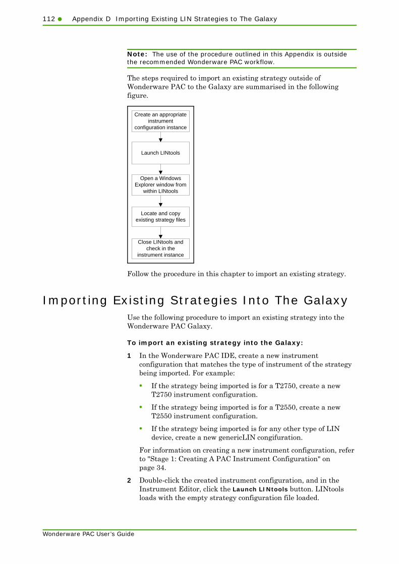
112 Appendix D Importing Existing LIN Strategies to The Galaxy
Note: The use of the procedure outlined in this Appendix is outside the recommended Wonderware PAC workflow.
The steps required to import an existing strategy outside of Wonderware PAC to the Galaxy are summarised in the following figure.
Follow the procedure in this chapter to import an existing strategy.
Importing Existing Strategies Into The GalaxyUse the following procedure to import an existing strategy into the Wonderware PAC Galaxy.
To import an existing strategy into the Galaxy:
1 In the Wonderware PAC IDE, create a new instrument configuration that matches the type of instrument of the strategy being imported. For example:
• If the strategy being imported is for a T2750, create a new T2750 instrument configuration.
• If the strategy being imported is for a T2550, create a new T2550 instrument configuration.
• If the strategy being imported is for any other type of LIN device, create a new genericLIN congifuration.
For information on creating a new instrument configuration, refer to "Stage 1: Creating A PAC Instrument Configuration" on page 34.
2 Double-click the created instrument configuration, and in the Instrument Editor, click the Launch LINtools button. LINtools loads with the empty strategy configuration file loaded.
Create an appropriate instrument
configuration instance
Launch LINtools
Open a Windows Explorer window from
within LINtools
Locate and copy existing strategy files
Close LINtools and check in the
instrument instance
Wonderware PAC User’s Guide

Importing Existing Strategies Into The Galaxy113
3 In LINtools, right-click on the root of the folder tree in the Contents window, and select Explore. The following figure shows this step, for a GenericLIN device.
Windows Explorer™ opens, showing the list of files in the checkedout directory.
4 In another Explorer window, locate the existing strategy configuration files, and copy these to the checkedout directory, overwriting the files as necessary.
Important: The instrument configuration type (T2750, T2550, or a generic LIN device) must match that of the device being imported into the Galaxy.
5 Set the default database to match the name of the database just imported. To do this, select Instrument Folder Properties from the File menu (or right-click on the top-level folder in the Contents window and select Properties). In the Instrument Folder Properties window, select the default database in the Default DB field. Once complete, click the OK button to close the window.
6 Close both Explorer windows and close LINtools. Check the instrument configuration back into the Galaxy.
..and selectExplorefrom themenu
Right-click on the root of the folder tree...
Wonderware PAC User’s Guide

114 Appendix D Importing Existing LIN Strategies to The Galaxy
The strategy configuration files are now stored in the Galaxy. Remember to edit this copy of the files (within Wonderware PAC) if any changes are to be made to the instrument configuration.
Wonderware PAC User’s Guide

115
Wonderware PAC User’s Guide
Appendix E
TroubleshootingCommunication Errors
This appendix provides information on troubleshooting communication errors between ArchestrA and a PAC Instrument. Troubleshooting procedures and a summary of each troubleshooting tool is provided, to aid the diagnosis and resolution of a problem.
This chapter contains the following sections:
• Troubleshooting Procedures
• Troubleshooting Tools
• Namespace Updates
Troubleshooting ProceduresDepending at which stage a communications problem is encountered, the method to troubleshoot changes accordingly. Refer to the following list to determine which flowchart to follow to help diagnose the communication problem.
• For communication problems with LIN instruments at the time of downloading a strategy (using LINtools or the Instrument Options editor), refer to "Troubleshooting at Strategy Download Time" on page 116.
• For communication problems when confirming a deployment of a DIDevice using the Object Viewer, refer to "Troubleshooting Deployed Devices" on page 116.
• For communication problems associated with the inability to write to a LIN instrument (but reading from a instrument works), refer to "Troubleshooting Write Failures" on page 118.

116 Appendix E Troubleshooting Communication Errors
Wonderware PAC User’s Guide
• For communication problems that occur when using InTouch, refer to "Troubleshooting InTouch Data Communications" on page 119.
Troubleshooting at Strategy Download TimeIf an instrument strategy cannot be downloaded to an instrument, the steps outlined in the following flowchart may aid the troubleshooting process. The bold text shows which tool to use in order to perform the troubleshooting. Refer to the appropriate section in this chapter for details on using the tool. An introduction to the troubleshooting tools is given in the section, "Troubleshooting Tools" on page 119.
Troubleshooting Deployed DevicesOnce a DIDevice has been deployed, it is recommended to ensure the deployed instrument is communicating successfully across the network. The System Management Console (SMC) can also be used to check for deployment errors.
Check LIN connectivity to instruments/
network
Network Explorer
Check cross subnet settings Network UNH
Check physical network
connection to instrument
Ping
Successful ping?
Check general networking setup (eg, IP address,
subnet mask, etc)
Check for error log entries
WindowsEvent Viewer
Windows Networking Configuration
No
Yes Check instrument network settings*
* Refer to documentation supplied with instrument for instructions.

Troubleshooting Procedures117
Wonderware PAC User’s Guide
The Object Viewer tool can be used to confirm successful communication with a DIDevice, and is therefore also a good tool for troubleshooting purposes.
Using the Object Viewer, confirm whether the objects are retrieving real data from the LIN instrument. If not, follow the steps shown in the following flowchart. Start with the steps in the left flowchart at the Engineering Workstation computer, and if the problem is not solved, use the right flowchart at the DAServer node. The bold text shows which tool to use in order to perform the troubleshooting. Refer to the appropriate section in this chapter for details on using the tool. An introduction to the troubleshooting tools is given in the section, "Troubleshooting Tools" on page 119.
If the problem is not resolved by the last step, refer to "Troubleshooting at Strategy Download Time" on page 116 for additional help.
Open a watch window template
(showing DI diagnostics)
Check the instrument database is downloaded
DI objects deployed?
Use the SMC to investigate non-
deployment
Check the DI object is linked to
the correct strategy config.
No
Yes
Check DINetwork settings, including
cross subnet settings
Object Viewer
Network ExplorerorLINTools
IDE Object Configurator
System Management Console (DAServer Manager)
IDE Object Configurator
Part 2
Check DAServer Manager for
running status of DAServer
Check any installed firewall is
not blocking LINOPC comms
Check SMC log for “failure to add”
entries
Check the Windows Event
Viewer
Follow the procedure to troubleshoot at Strategy
Download time
System Management Console (DA Server Manager)
Wonderware Logger (via the SMC)
Windows Event Viewer
The following steps should be performed on the DA Server node (not
the IDE)
Part 2
Windows /3rd party firewall
Engineering Workstation computer DAServer node

118 Appendix E Troubleshooting Communication Errors
Wonderware PAC User’s Guide
Troubleshooting Write FailuresIf the Object Viewer demonstrates that data can be read from the LIN device, but cannot be written, there are a number of areas to check, as shown in the following flowchart. The bold text shows which tool to use in order to perform the troubleshooting. Refer to the appropriate section in this chapter for details on using the tool. An introduction to the troubleshooting tools is given in the section, "Troubleshooting Tools" on page 119.
If the problem is not resolved by the last step, refer to "Troubleshooting Deployed Devices" on page 116 for additional help.
Check ArchestrA security settings
Check the Windows Regional
Settings
Check for SMC log entries
Check the Windows Event
log
Follow the procedure to troubleshoot Deployed
Devices
Wonderware logger (via the SMC)
Windows Event Viewer
Windows Regional Settings Control Panel
ArchestrA Security Editor
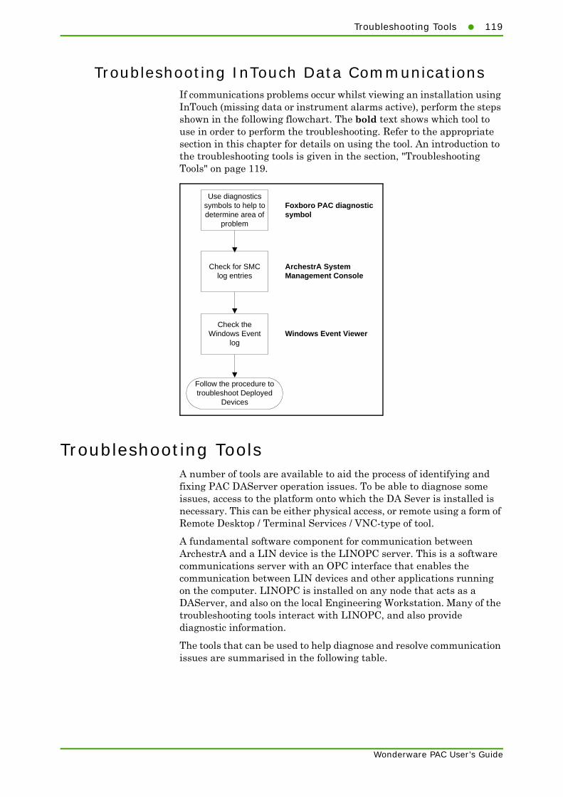
Troubleshooting Tools119
Wonderware PAC User’s Guide
Troubleshooting InTouch Data CommunicationsIf communications problems occur whilst viewing an installation using InTouch (missing data or instrument alarms active), perform the steps shown in the following flowchart. The bold text shows which tool to use in order to perform the troubleshooting. Refer to the appropriate section in this chapter for details on using the tool. An introduction to the troubleshooting tools is given in the section, "Troubleshooting Tools" on page 119.
Troubleshooting ToolsA number of tools are available to aid the process of identifying and fixing PAC DAServer operation issues. To be able to diagnose some issues, access to the platform onto which the DA Sever is installed is necessary. This can be either physical access, or remote using a form of Remote Desktop / Terminal Services / VNC-type of tool.
A fundamental software component for communication between ArchestrA and a LIN device is the LINOPC server. This is a software communications server with an OPC interface that enables the communication between LIN devices and other applications running on the computer. LINOPC is installed on any node that acts as a DAServer, and also on the local Engineering Workstation. Many of the troubleshooting tools interact with LINOPC, and also provide diagnostic information.
The tools that can be used to help diagnose and resolve communication issues are summarised in the following table.
Use diagnostics symbols to help to determine area of
problem
Check for SMC log entries
Check the Windows Event
log
Follow the procedure to troubleshoot Deployed
Devices
Foxboro PAC diagnostic symbol
ArchestrA System Management Console
Windows Event Viewer

120 Appendix E Troubleshooting Communication Errors
Wonderware PAC User’s Guide
Tool Purpose Overview
Network Explorer(page 121)
Check LIN connectivity to instruments / network
Provides local browsing of LIN–based networks and allows the starting and stopping of instruments connected to the network. Information on connected instruments is also shown, including the instrument type, database name, run state and synchronisation state.
Network UNH(page 122)
Check cross subnet settings
Provides the ability to configure the network UNH file, and define the subnet configuration on the instrument.
Ping (page 123) Check physical network connection to instrument
A standard networking tool that tests whether a particular host is reachable across the IP network.
Windows Networking Configuration (page 123)
Check general networking setup
Microsoft Windows built-in configuration control panels to configure the networking capabilities of a PC.
Windows Event Viewer (page 128)
Check for error log entries
Significant events relating to LINOPC deployment and PAC DAServer operation are logged to the standard Windows Event Logger.
Object Viewer (page 124)
View diagnostic information within an object
Provides the ability to show an object’s data value, data quality and the communication status of the object.
LINTools (page 124) Check the right database, and blocks are in the instrument
Provides the ability to create and edit instrument strategies. In an Online mode, the instrument can be interrogated to confirm runtime operation and correct database download.
System Management Console (page 125)
Check for deployment information / Check DAServer Manager for running status of DAServer
Provides the ability to obtain additional diagnostic information for the PAC DAServer, including data on client groups, statistics, messages, and device groups.
IDE Object Configurator (page 129)
Check the DI object is linked to the correct strategy configuration / Check DINetworking settings, including cross subnet settings
Allows an object’s attributes and properties to be defined within the Archestra IDE.
Windows / Third–Party Firewall (page 130)
Check firewall is not blocking LINOPC communications
Controls whether communication between computer networks or hosts is permitted or blocked.

Troubleshooting Tools121
Wonderware PAC User’s Guide
Network ExplorerThe Network Explorer tool allows the user to browse the locally connected LIN-based network/s and view a status summary for each device. In doing so, LIN connectivity to the instruments can be confirmed. Information presented for discovered instruments includes the instrument type, current database, run state and synchronisation state. The status area at the bottom of the window can also provide diagnostic information.
ArchestrA Security Editor (page 132)
Check for security issues that may be blocking commununication
Defines the security policy used within the ArchestrA framework, specifying the scope that users may interact with objects, perform maintenance tasks, and control and respond to run-time operations.
Windows Regional Settings (page 132)
Check that the regional settings format numbers correctly.
Defines various regional settings on a Windows workstation or server, including how numbers, currency, time and dates are formatted.
Wonderware Logger (page 128)
Check SMC log for “failure to add” entries, or other errors
Significant events relating to deployment and PAC DAServer operation are logged to this logger, accessed through the SMC.
Foxboro PAC Diagnostic Symbol (page 133)
Use diagnostic symbols to help determine area of problem
Provides diagnostic information for a specific DIDevice object. The symbol replicates the important diagnostic blocks in the Wonderware PAC device, and provides both a summary window for the complete instrument, and a detail window for full analysis of alarms and communication status.
Shutdown LINOPC Utility (page 125)
Ensure the LINOPC server hasn’t hung
Provides the ability to forcibly shutdown any running instances of the LINOPC server.
LIN Ports Editor Control Panel (page 130)
Manually check LINOPC configuration, including IP address allocation
The LIN Ports Editor control panel defines the port and node details for the LIN network, and also configures the IP address. Use the tool to check the settings are as expected.
Namespace Updates (page 133)
Force namespace update and distribution
By checking the date and time the namespace was last updated, namespace propagation issues can be detected.
Tool Purpose Overview

122 Appendix E Troubleshooting Communication Errors
Wonderware PAC User’s Guide
The Network Explorer tool can be launched from the IDE workstation, by selecting Network Explorer from the Invensys subgroup on the Start menu. The following figure shows an example of the Network Explorer.
Additional help concerning the use of the Network Explorer is available using the online help (by clicking the Help button).
If the status area reports the error, “Fail : 0xA7C5 - Unable to determine which interface to use”, then multiple network adapters are installed in the Engineering Workstation and the IP address for the LINOPC connection has not been specified. Consequently, LINOPC is unable to determine which IP address to assign to the LINOPC connection. Refer to the section, "LIN Ports Editor Control Panel" on page 130 for details on typical settings to define in the Edit IP Info window of the LIN Ports Editor control panel.
Note: The Network Explorer tool is not installed on a DAServer node. Use the local LIN connection from the engineering workstation to establish communication with the LIN instrument.
Network UNHThe network UNH file is stored within LIN instruments, and is used to configure the instrument’s Ethernet communication, including the cross-subnet configuration.
To edit the network UNH, open the instrument configuration editor for a strategy within the IDE, and click the Instrument Options button. The Ethernet settings are configured within the Network Settings tab.
Statusarea

Troubleshooting Tools123
Wonderware PAC User’s Guide
PingPing is a standard network diagnostic tool used to test whether a particular host is reachable across the IP network. This allows a check of the physical network connection to a LIN instrument. The ping command is available through a Windows command prompt. There are many ways to display a Windows command prompt, but the method shown below should operate on all versions of Windows.
• Display the Run window by clicking on the Start Menu and choose Run (or press the Windows key and R). The Run window displays.
• Enter cmd in the window and press the Enter key. A command prompt appears.
• In the command prompt, enter ping <instrument IP Address>, where the <instrument IP Address> is the IP address of the instrument to which communication has failed.
• If communication with the remote host fails, the ping tool displays Request timed out. Otherwise, the size of the reply, time taken, and time to live (TTL) values are displayed, indicating a successful response from the instrument.
• To close the command prompt, type exit and press the Enter key. The command prompt window closes.
Windows Networking ConfigurationThere are two areas in which the network configuration should be checked. First is confirm the Windows network configuration, and the second is to confirm LINOPC is assigned the correct network settings.
To confirm the Windows network configuration, launch the Networking Connections control panel, and locate each of the network adapters installed in the Engineering Workstation. By default, these are called Local Area Connection, but they may be renamed depending on your particular setup and policies. For each network adapter, confirm the TCP/IP settings are defined as per the IT guidelines for the site.
To confirm the LINOPC network settings, launch the LIN Ports Editor control panel. Refer to the section, "LIN Ports Editor Control Panel" on page 130 for details on how to launch the control panel. In a typical configuration, the LINOPC IP address is the same as the network card’s IP address, enabling it to communicate with LIN instruments on the LIN network.

124 Appendix E Troubleshooting Communication Errors
Wonderware PAC User’s Guide
Object ViewerThe Object Viewer utility offers the ability to show an object’s data value, data quality and the communication status of the object. In addition, the tool can be used to show performance and diagnostic information about ApplicationObjects. The use of Object Viewer is strongly recommended when deploying a DIDevice as it provides a convenient way to test that the LIN data that the DIDevice exposes is readable within the Wonderware PAC framework.
Using the Object Viewer, it is possible to:
• View the data type, data quality, data value, timestamp, and communication status of ApplicationObject attributes
• Perform diagnostic testing on ApplicationObjects
• Modify selected ApplicationObject attributes.
The Object Viewer is started from within the IDE by right-clicking on a deployed DIDevice object, and clicking View in Object Viewer. The Object Viewer can also be access from within the System Management Console.
To check deployment of a DINetwork object, add an Attribute Reference for the OPC watchdog timer. For example, for a deployed DINetwork called PAC_DINetwork_001, add the following Attribute Reference to a Watch Window:
PAC_DINetwork_001.$LINOPC.OPCWatchdog
For further information concerning the operation of Object Viewer, see the Object Viewer User’s Guide.
LINToolsThe LINTools application is the primary tool for the creation and maintenance of LIN instrument strategies.
In a trouble-shooting context, LINTools can provide information about the live status of an instrument by using the Online Connect facility. This allows the user the view the current state of the LIN function blocks within the instrument, and confirm that the correct database has been downloaded. If the instrument isn’t running in a live environment, the database can be re-downloaded, if desired.
Caution: Downloading a strategy to an instrument running in a live environment will temporarily disrupt control.
For information on using LINTools in a Wonderware PAC context, refer to "Wonderware PAC Basics" on page 33. For detailed information on using LINTools, refer to the LINtools Engineering Studio User Guide.

Troubleshooting Tools125
Wonderware PAC User’s Guide
Shutdown LINOPC UtilityThe LINOPC server is a software communications server with an OPC interface that enables the communication between LIN devices and other applications running on the computer. The LINOPC server automatically launches when a request for LIN data is made, and after a period of no activity, closes.
The LINOPC server is used both at deployed DAServer instances, and locally on the Engineering Workstation (where it is used to enable strategy downloads to LIN instruments).
Should the LINOPC server not shutdown, it can be forcibly terminated by running the Shutdown LINOPC utility. Some changes to the DINetwork object, including a change of port name or node address, require the LINOPC server to restart to apply the changes. This restart should be automatic but if it fails, the Shutdown LINOPC utility may be used.
The Shutdown LINOPC utility can be found from the start menu in the Program Files > Invensys > Utilities subgroup.
The utility does not require any user input, and takes between one to ten seconds to complete, after which the utility closes.
System Management ConsoleThe System Management Console (SMC) is a management application built around the Microsoft™ Management Console architecture. The SMC provides a central location for the administration of various servers and applications that form part of the ArchestrA framework.
The SMC has the ability to manipulate configuration settings for the PAC DAServer, and to provide diagnostic information regarding the server, including data on client groups, statistics, messages and device groups. Only the diagnostic information should be used to help diagnose PAC DAServer issues, as the configuration of a PAC DAServer should always be performed from within the IDE, and not the SMC.
Log files recorded on remote nodes (such as the DAServer) are accessible in the SMC on the engineering workstation (refer to "Wonderware Logger" on page 128). However, the Diagnostic folder tree within the SMC can only be viewed locally. Therefore, for DAServer nodes, either physical access to the node, or remote viewing (remote desktop, VLC, etc) is required to view the diagnostic information.
Important: Do not alter any configuration for a PAC DAServer using the SMC. Unpredictable results and server failure may occur. Only configure a PAC DAServer from within the ArchestrA IDE.

126 Appendix E Troubleshooting Communication Errors
Wonderware PAC User’s Guide
To obtain diagnostic information for a PAC DAServer using the SMC
1 Launch the SMC from the start menu on the node for which diagnostic information is required. The SMC is located in the Program Files > Wonderware subgroup. The SMC opens.
2 Expand the DAServer Manager folder on the left by clicking the small plus (+) symbol. A list of the Galaxies known to the server are displayed.
3 Expand the appropriate Galaxy folder and then the WinPlatform object folder. One or more PAC DAServers are shown.

Troubleshooting Tools127
Wonderware PAC User’s Guide
4 Expand the appropriate DAServer (InvensysSystemsInc.PACDAServer.1 in the example) to reveal the Configuration and Diagnostics folders.
5 Expand the Diagnostics folder to see a list of diagnostic categories that can be viewed.
Important: Do not make any changes to the settings within the Configuration folder. Unpredictable results may occur. Only make configuration changes to the PAC DAServer using the IDE.
6 From here, the examination of the diagnostic information within the Diagnostic folder may help reveal the cause of any PAC DAServer issues.
The Client Groups folder is particularly useful for diagnostics purposes. It shows a summary of all items per DIDevice, and provides information on the number of items, active items, errors, state, quality and state. The information presented updates in real-time.
For further information on the Diagnostics component, refer to the online help in the SMC. Specifically, help is available on the Diagnostics component by navigating the online help to DAServer Manager Online Help > Using Online Help > DAServer Manager > Diagnostics Component.
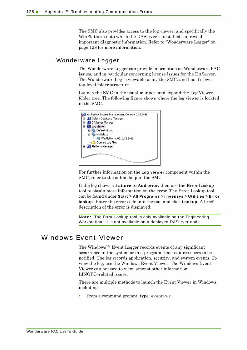
128 Appendix E Troubleshooting Communication Errors
Wonderware PAC User’s Guide
The SMC also provides access to the log viewer, and specifically the WinPlatform onto which the DAServer is installed can reveal important diagnostic information. Refer to "Wonderware Logger" on page 128 for more information.
Wonderware LoggerThe Wonderware Logger can provide information on Wonderware PAC issues, and in particular concerning license issues for the DAServer. The Wonderware Log is viewable using the SMC, and has it’s own top-level folder structure.
Launch the SMC in the usual manner, and expand the Log Viewer folder tree. The following figure shows where the log viewer is located in the SMC.
For further information on the Log viewer component within the SMC, refer to the online help in the SMC.
If the log shows a Failure to Add error, then use the Error Lookup tool to obtain more information on the error. The Error Lookup tool can be found under Start > All Programs > Invensys > Utilities > Error lookup. Enter the error code into the tool and click Lookup. A brief description of the error is displayed.
Note: The Error Lookup tool is only available on the Engineering Workstation; it is not available on a deployed DAServer node.
Windows Event ViewerThe Windows™ Event Logger records events of any significant occurrence in the system or in a program that requires users to be notified. The log records application, security, and system events. To view the log, use the Windows Event Viewer. The Windows Event Viewer can be used to view, amonst other information, LINOPC–related issues.
There are multiple methods to launch the Event Viewer in Windows, including:
• From a command prompt, type: eventvwr

Troubleshooting Tools129
Wonderware PAC User’s Guide
• Click start, and then click Control Panel. Click Performance and Maintenance (if viewing Control Panels grouped in categories), and then double-click Administrative Tools. Finally, double-click Event Viewer.
• Right-click My Computer and select Manage. From the resulting Computer Management dialogue box, expand the Event Viewer folder under System Tools.
Any of the methods launches the Event Viewer application.
By default, the Event Viewer records three logs:
• Application log — contains events logged by programs. Wonderware PAC and the PAC DAServer (including support software such as LINOPC) write entries to this log.
• Security log — contains events such as valid and invalid logon attempts, and well as events related to resource use, such as the creating, opening, or deleting of files.
• System log — contains events logged by Windows system components. For example, if a driver fails to load during startup, the event is written to the system log. DCOM errors may be written to this log.
IDE Object ConfiguratorThe IDE Object Configurator is part of core ArchestrA functionality, allowing the attributes and properties for an object to be edited. Double click on an instance of an object to view the object in the Object Configurator.
In a troubleshooting context, use the IDE Object Configurator to check:
• the correct instrument strategy has been assigned to a DIDevice object
• the correct LIN Protocol Name, and Node Address (in hex) has been assigned to a DINetwork object

130 Appendix E Troubleshooting Communication Errors
Wonderware PAC User’s Guide
• if cross-subnet communication is required, confirm the Enable cross-subnet communication checkbox for the DINetwork object is ticked, and relevant IP addresses listed.
Windows / Third–Party FirewallThe firewall requirements for Wonderware PAC are the same as for a standard ArchestrA installation.
However, in addition, Engineering Workstations need to communicate with LIN instruments in order to download a configuration strategy, and test the communications. They should therefore be configured to ensure that all UDP ports between 1024 and 65535 are unblocked, as LINOPC uses these ports to communicate with the instruments.
LIN Ports Editor Control PanelThe LIN Ports Editor control panel provides access to the local configuration for the LINOPC server. The basic settings that this control panel provides can be controlled using the LIN Connection Setup tool within the IDE. Refer to "Using the LIN Connection Setup Tool" on page 44 for further information.
At the point of deploying a DINetwork object, LINOPC is automatically installed and configured to match the settings defined within the Galaxy.
Note: The LIN Ports Editor control panel should only be used to troubleshoot DA Sever issues. Deploying a DINetwork will override some settings manually adjusted using this tool.
However, there may be circumstances whereby the configuration of LINOPC does not exactly match the desired settings, or only partly configured. As part of troubleshooting a PAC DAServer, the LIN Ports Editor control panel should be checked that the settings are as expected.
The LIN Ports Editor control panel is a standard Windows control panel, and can be found in the standard control panel location. There are multiple methods to access control panels in Windows, including:
• From the start menu, select control panel
• From My Computer select control panel
• From a command prompt, type: control
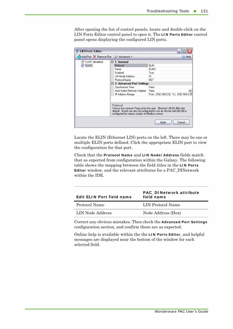
Troubleshooting Tools131
Wonderware PAC User’s Guide
After opening the list of control panels, locate and double-click on the LIN Ports Editor control panel to open it. The LIN Ports Editor control panel opens displaying the configured LIN ports.
Locate the ELIN (Ethernet LIN) ports on the left. There may be one or multiple ELIN ports defined. Click the appropriate ELIN port to view the configuration for that port.
Check that the Protocol Name and LIN Node/Address fields match that as expected from configuration within the Galaxy. The following table shows the mapping between the field titles in the LIN Ports Editor window, and the relevant attributes for a PAC_DINetwork within the IDE.
Correct any obvious mistakes. Then check the Advanced Port Settings configuration section, and confirm these are as expected.
Online help is available within the the LIN Ports Editor, and helpful messages are displayed near the bottom of the window for each selected field.
Edit ELIN Port field namePAC_DINetwork attribute field name
Protocol Name LIN Protocol Name
LIN Node Address Node Address (Hex)

132 Appendix E Troubleshooting Communication Errors
Wonderware PAC User’s Guide
Close the LIN Ports Editor control panel window by clicking on the Apply button. If any changes were made to the configuration, the LINOPC server may need to restart to apply the changes. A dialogue box is displayed to confirm this operation if it is required.
Click Yes to allow the LINOPC server to restart with the new configuration.
ArchestrA Security EditorThe security infrastructure for Wonderware PAC uses the standard ArchestrA security model. This model allows the management of access to:
• the IDE for configuring and managing objects
• the SMC for maintenance and system administration functions
• any run-time operations.
Verify the security settings, especially if write failures occur.
For information on using the Security Editor, see the Working with Security chapter in the Wonderware Application Server User’s Guide.
Windows Regional SettingsMicrosoft Windows allows users to adjust the formatting of numbers and dates according to their geographic location, reflecting the regional normals for representing this information. However, in order for ArchestrA, Foxboro PAC, and LIN instruments to communicate successfully, the regional settings needs to be standardised. Therefore, within the Windows Regional Settings control panel, ensure:
• the number format is set to English (UK or US) standard.
• numbers use a decimal point to represent any number to greater accuracy than a whole number (for example 10.5 meaning ten and a half). In some regions, it is common to use a comma (,) as the decimal point symbol.
• all computers connected to the Supervisory network are set to the same standard.

Namespace Updates133
Wonderware PAC User’s Guide
Foxboro PAC Diagnostic SymbolIn order to troubleshoot a Foxboro PAC instrument, a diagnostic symbol can be attached to a DIDevice object. The symbol replicates the important diagnostic blocks in the Foxboro PAC device, and provides both a summary window for the complete instrument, and a detail window for full analysis of alarms and communication issues.
Refer to "Instrument Diagnostics" on page 75 for further details.
Namespace UpdatesThe Wonderware PAC namespace is a complete representation of the data that exists in a set of instrument configurations. It is a fundamental lookup table for the operation of Wonderware PAC.
When changes to the configuration are made in the Galaxy, a PAC DAServer needs to know about any namespace changes. This is especially applicable if new objects have been added. The distribution of the namespace information to the node(s) where the DAServer is running is automatic when instrument configurations are checked into the Galaxy. The configuration-time namespace is updated when a database is saved from LINtools.
The LIN Data Browser tab within the Galaxy Browser tool does not use the distributed/runtime namespace. Instead, it uses the offline configuration-time namespace. If the expected namespace information is presented in the Galaxy Browser, this does not imply that the runtime namespace is 100% complete.
The runtime namespace is a distributed copy of the offline configuration-time namespace. It is only available when a platform from the relevant Galaxy is currently deployed to a node. The offline namespace is always available, regardless of which objects are currently deployed, and this is why configuration interfaces (like the Galaxy Browser) do not use the run-time namespace.
If namespace update issues are suspected, then the respective namespaces can be forced to be updated for a particular object.
To force an update for the runtime namespace:
1 Check out the suspected object from the Galaxy.
2 Make a change to the configuration (for example, re-enter the node address to what it already is).
3 Check the object back into the Galaxy.
The runtime namespace will update with the information contained within the object. An instance where this procedure may be particularly useful might be when importing an object into a different Galaxy.
To force an update for the offline configuration-time namespace:
1 Check out a suspected instrument configuration from the Galaxy.

134 Appendix E Troubleshooting Communication Errors
Wonderware PAC User’s Guide
2 Launch LINtools to edit the strategy.
3 Reposition a block in the strategy (GRF).
4 Close LINtools and save the database.
5 Check the instrument configuration object back into the Galaxy.

135
Wonderware PAC User’s Guide
Appendix F
Using LINtools in aWonderware PAC Context
This appendix provides information on using LINtools in an Wonderware PAC context, highlighting the small changes that an existing LINtools user may notice.
This chapter contains the following sections:
• Overview
• Disabled Commands
• Wonderware PAC User–Interface Changes
• General User–Interface Changes
• Workflow Changes
OverviewUsers familiar with LINtools may notice some changes to the user interface within LINtools when working in the context of Wonderware PAC. The changes are minor, but necessary because some of the commands and menu options are not applicable in the Wonderware PAC context. The following sections show the differences.
Disabled CommandsThe following menu commands have been disabled within LINtools:

136 Appendix F Using LINtools in a Wonderware PAC Context
Wonderware PAC User’s Guide
Wonderware PAC User–Interface ChangesThere are small changes to the user interface in LINtools when running within the Wonderware PAC framework. This section describes those changes.
Instrument NameOutside the Wonderware PAC context, LINtools displays the folder name in the Contents window under “Instrument”. As folders have no significance within Wonderware PAC, the name displayed is the name of the instrument as defined within the IDE.
Read-only ConfigurationsIn Wonderware PAC, a second user may check out a read-only copy of an object if another user currently has the same object checked out. Similarly, a user may decide to check out an instrument configuration in an read-only state. When LINtools is launched, and the configuration object is in a read-only state, the words read only are appended to the LINtools title bar. In this mode, LINtools opens the configuration as read–only, so no modifications can be saved. It is possible, however, to download the strategy or go online to the instrument.
Menu Command Description
File > New Instrument Folder
New instruments are created from within the ArchestrA IDE, and the concept of instrument folders does not exist within the Wonderware PAC framework. The New Instrument Folder command is therefore not available. Use the IDE environment to create new instrument configurations instead. Refer to "Stage 1: Creating A PAC Instrument Configuration" on page 34 to create new instrument configurations.
File > Get Me Started New instruments and folders are created from within the ArchestrA IDE, and the starting point for any instrument configuration should be made from Wonderware PAC. Refer to Chapter 2, "Wonderware PAC Basics," for information on the workflow for Foxboro PAC instruments (and generic LIN devices).
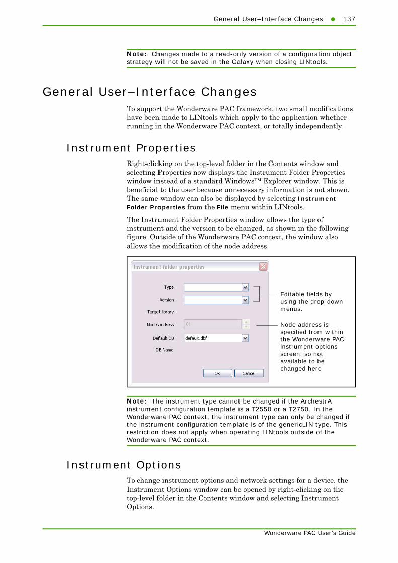
General User–Interface Changes137
Wonderware PAC User’s Guide
Note: Changes made to a read-only version of a configuration object strategy will not be saved in the Galaxy when closing LINtools.
General User–Interface ChangesTo support the Wonderware PAC framework, two small modifications have been made to LINtools which apply to the application whether running in the Wonderware PAC context, or totally independently.
Instrument PropertiesRight-clicking on the top-level folder in the Contents window and selecting Properties now displays the Instrument Folder Properties window instead of a standard Windows™ Explorer window. This is beneficial to the user because unnecessary information is not shown. The same window can also be displayed by selecting Instrument Folder Properties from the File menu within LINtools.
The Instrument Folder Properties window allows the type of instrument and the version to be changed, as shown in the following figure. Outside of the Wonderware PAC context, the window also allows the modification of the node address.
Note: The instrument type cannot be changed if the ArchestrA instrument configuration template is a T2550 or a T2750. In the Wonderware PAC context, the instrument type can only be changed if the instrument configuration template is of the genericLIN type. This restriction does not apply when operating LINtools outside of the Wonderware PAC context.
Instrument OptionsTo change instrument options and network settings for a device, the Instrument Options window can be opened by right-clicking on the top-level folder in the Contents window and selecting Instrument Options.
Editable fields byusing the drop-downmenus.
Node address isspecified from withinthe Wonderware PACinstrument optionsscreen, so notavailable to bechanged here

138 Appendix F Using LINtools in a Wonderware PAC Context
Wonderware PAC User’s Guide
The same window can be displayed in the Wonderware PAC IDE by selecting Instrument Options from within the instrument configuration screen.
Workflow ChangesIn some cases, the way a user performs an operation is different within the Wonderware PAC context. This section shows the changes.
Changing the Instrument Version or TypeBy default, new $T2750 and $T2550 configuration objects have the most recent major version of the default database defined. There may be circumstances when the user may want an older instrument version (for example, when working with a legacy system).
To change the instrument version or type, display the Instrument Folder Properties window and make the changes here. Refer to "Instrument Properties" on page 137 for information on displaying the window. Full information on this functionality can be found in the section, "Changing the Instrument Version" on page 42.

139
Wonderware PAC User’s Guide
Appendix G
Enabling Cross-SubnetCommunication
This appendix provides information on enabling cross-subnet communication. It contains the following sections:
• Overview
• Configuration

140 Appendix G Enabling Cross-Subnet Communication
Wonderware PAC User’s Guide
OverviewCross-subnet communication is an advanced feature only required if instruments are on a separate subnet from the Engineering Workstations, DINetworks, or InTouch application servers. An example scenario of such an architecture is shown in the following figure.
ConfigurationConfiguring a system to work across subnets involves several steps, as follows:
• Any instruments that are attached to the network in a different subnet must be configured so that they are aware of the workstations and nodes in the subnet. Refer to "Instrument Configuration" on page 141.
• The Engineering Workstation needs to be configured to allow cross-subnet communication. Refer to "Engineering Workstation Configuration" on page 142.
• Any deployed DINetworks must have the option to communicate across subnets selected. Refer to "Deployed DINetwork Configuration" on page 143.
Supervisory EthernetNetwork
LIN “Control”Ethernet Network
Router
Subnet A Subnet B
LIN instrument
IDE Engineering Workstation
DINetwork (DAServer)
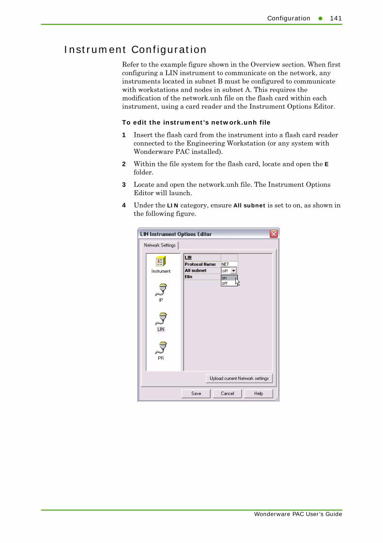
Configuration141
Wonderware PAC User’s Guide
Instrument ConfigurationRefer to the example figure shown in the Overview section. When first configuring a LIN instrument to communicate on the network, any instruments located in subnet B must be configured to communicate with workstations and nodes in subnet A. This requires the modification of the network.unh file on the flash card within each instrument, using a card reader and the Instrument Options Editor.
To edit the instrument’s network.unh file
1 Insert the flash card from the instrument into a flash card reader connected to the Engineering Workstation (or any system with Wonderware PAC installed).
2 Within the file system for the flash card, locate and open the E folder.
3 Locate and open the network.unh file. The Instrument Options Editor will launch.
4 Under the LIN category, ensure All subnet is set to on, as shown in the following figure.

142 Appendix G Enabling Cross-Subnet Communication
Wonderware PAC User’s Guide
5 Under the PR category, enter the IP address of each workstation and node in Subnet A, with which the instrument in Subnet B needs to communicate. An example is shown in the following figure.
The instrument must also have a valid default gateway configured in order to function properly. This is set up under the IP section of the Instrument Options Editor. Select either DHCP configuration or enter the IP address details manually. Configuration of the basic network settings is part of the standard instrument configuration.
After updating the network.unh file of an instrument, the instrument must be power-cycled in order for the changes to take effect.
Engineering Workstation ConfigurationTo enable an Engineering Workstation to communicate with instruments that have already been configured to communicate across subnets, the LIN Connection Setup tool is used. Tick the checkbox labelled Enable cross-subnet communication in the LIN Connection Setup window. Refer to "Using the LIN Connection Setup Tool" on page 44 for further information.

Configuration143
Wonderware PAC User’s Guide
Deployed DINetwork ConfigurationTo configure a DINetwork to communicate across subnets, open the PAC_DINetwork for each node in subnet A that needs to communicate with instruments on subnet B, and tick the Enable cross-subnet communication option. The extra field, PR IP Addresses, which appears can be left blank.
Select to enable cross-subnet communication

144 Appendix G Enabling Cross-Subnet Communication
Wonderware PAC User’s Guide
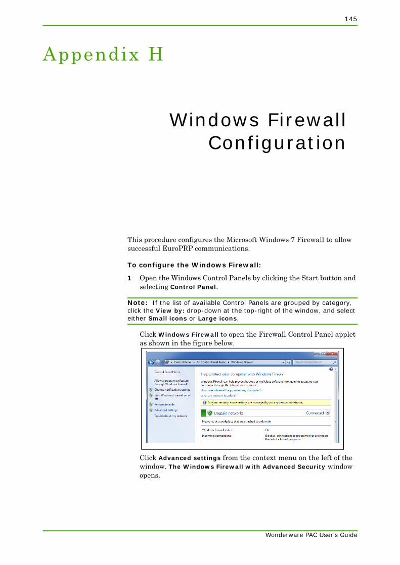
145
Wonderware PAC User’s Guide
Appendix H
Windows FirewallConfiguration
This procedure configures the Microsoft Windows 7 Firewall to allow successful EuroPRP communications.
To configure the Windows Firewall:
1 Open the Windows Control Panels by clicking the Start button and selecting Control Panel.
Note: If the list of available Control Panels are grouped by category, click the View by: drop-down at the top-right of the window, and select either Small icons or Large icons.
Click Windows Firewall to open the Firewall Control Panel applet as shown in the figure below.
Click Advanced settings from the context menu on the left of the window. The Windows Firewall with Advanced Security window opens.

146 Appendix H Windows Firewall Configuration
Wonderware PAC User’s Guide
2 Select Inbound Rules from the choices on the left and sort the resulting list by name to locate all entries for EuroPRP, as shown in the following figure.
Each rule is either an Allow rule (shown with a green tick) or a Blocking rule (shown with a red no-entry symbol).
3 For each EuroPRP Blocking rule, check the profile column. If the profile matches your instrument network type, then delete the rule. Repeat for each EuroPRP Blocking rule.
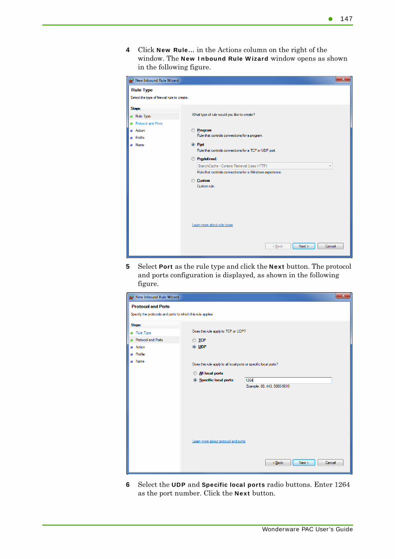
147
Wonderware PAC User’s Guide
4 Click New Rule... in the Actions column on the right of the window. The New Inbound Rule Wizard window opens as shown in the following figure.
5 Select Port as the rule type and click the Next button. The protocol and ports configuration is displayed, as shown in the following figure.
6 Select the UDP and Specific local ports radio buttons. Enter 1264 as the port number. Click the Next button.

148 Appendix H Windows Firewall Configuration
Wonderware PAC User’s Guide
7 The Action configuration is displayed as shown in the following figure.
Select Allow the connection, and click the Next button.
8 The Profile configuration is displayed as shown in the following figure.
You can either allow the connection on all network types, or allow it only on your instrument network type. Select the appropriate tick boxes.

149
Wonderware PAC User’s Guide
Note: To determine your instrument network type, open the Windows Control Panels and open the Network and Sharing Centre. Your instrument will be listed under the View your active networks section. The network type will be one of "Public network", "Domain network", or "Private network".
9 Finally, name the new rule EuroPRP and click the Finish button.
The Windows Firewall is now configured to allow successful EuroPRP communication.

150 Appendix H Windows Firewall Configuration
Wonderware PAC User’s Guide
151
Glossary
application A collection of objects in a Galaxy Repository that performs an automation task. Synonymous with Galaxy. There can be one or more applications within a Galaxy Repository.
Application Engine (AppEngine)
A scan-based engine that hosts and executes the run time logic contained within AutomationObjects.
ApplicationObject An AutomationObject that represents some element of your application. This can include things like an automation process component. For example, a thermocouple, pump, motor, valve, reactor, or tank or associated application component. For example, function block, PID loop, Sequential Function Chart, Ladder Logic program, batch phase, or SPC data sheet
Application view The Applications view shows the object-related contents of the Galaxy in three different ways: Model view, Deployment view, and Derivation view. The Model view appears when the IDE is opened for the first time.
ArchestrA The distributed architecture for supervisory control and manufacturing information systems. It is an open and extensible technology based on a distributed, object-based design.
ArchestrA Object Toolkit
A programmer’s tool to create new ApplicationObjects and Device Integration Object (DIObjects) templates, including their configuration and run time implementations. Includes a tool to build Device Integration Object (DIObjects) and create unique Domain Objects that interact with DI Objects in the ArchestrA environment.
Area A logical grouping of AutomationObjects that represents an area or unit of a plant. It is used to group related AutomationObjects for alarm, history, and security purposes. It is represented by an Area AutomationObject.
Area Object The System object that represents an Area of your plant within a Galaxy. The Area Object acts as an alarm concentrator, and places other Automation Objects into proper context with respect to the actual physical automation layout.
assignment The designation of a host for an AutomationObject. For example, an AppEngine AutomationObject is assigned to a WinPlatform AutomationObject.
attribute An externally accessible data item of an AutomationObject.
Wonderware PAC User’s Guide

152
attribute reference string
A text string that references an attribute of an AutomationObject.
AutomationObject An object type that represents permanent things in your plant, such as ApplicationObject or Device Integration Object (DIObjects), with user-defined, unique names within the Galaxy. It provides a standard way to create, name, download, execute, and monitor the represented component.
AutomationObject Server (AOS)
A computer that hosts one or more application engines and associated automation objects. An Industrial Application Server Galaxy Namespace can contain several AutomationObject Server (AOS), each which requires a Platform.
backup AppEngine The object created by the ArchestrA infrastructure when the Primary object is enabled for redundancy. See redundancy for further details.
base template A root template at the top of a derived hierarchy. Unlike other templates, a base template is not derived from another template but developed with the ApplicationObject Toolkit and imported into a Galaxy. All templates names start with a $.
binding tool See PAC bining tool.
block read group A DAGroup that is triggered by the user or another object. It reads a block of data from the external data source and indicates the completion status.
block write group A DAGroup that is triggered by the user or another object after all the required data items are set. The block of data is sent to the external data device. When the block write is complete, it indicates the completion status.
bootstrap The base ArchestrA service which is required on all ArchestrA computers. It provides the base software environment to enable a platform and allows a computer to be included in the Galaxy Namespace.
change log The revision history that tracks the life cycle activities of ArchestrA Objects, such as object creation, check in/check out, deployment, and import/export.
change propagation The ability to create templates which allows each component template to support changes such that a change in one of the elements can be automatically propagated to all — or select, related — object instances.
check in IDE operation for making a configured object available for other users to check out and use.
check out IDE operation for the purpose of editing an object. It makes the item unavailable for other users to check out.
checkpoint The act of saving to disk the configuration, state, and all associated data necessary to support automatic restart of a running AutomationObject. The restarted object has the same configuration, state, and associated data as the last checkpoint image on disk.
Wonderware PAC User’s Guide

153
compound object An ApplicationObject that contains at least one other ApplicationObject.
contained name An alternate naming convention that, when combined with the tagname of the root container object, results in the hierarchical name. For example, for a given object, its Hierarchical Name = Line1.Tank1.InletValve and its Contained Name= InletValve.
containment A hierarchical grouping that allows one or more AutomationObject to exist within the name space of a parent AutomationObject and be treated like parts of the parent. Allows for relative referencing to be defined at the template and instance level.
DAGroup A data access group associated with Device Integration Object (DIObjects). It defines how communications are achieved with external data sources. It can be a scan group, block read group or block write group.
DAServer Manager (DAS Manager)
The System Management Console (SMC) snap-in supplied by the Data Access Server (DAServer) that provides the required interface for activation, configuration, and diagnosis of the DAServer.
Data Access Server (DAServer)
The server executable that handles all communications between field devices of a certain type and client applications. Similar to I/O Servers but with more advanced capabilities.
Data Access Server Toolkit (DAS Toolkit)
A developer tool that can build a Data Access Server (DAServer).
deployment The operation which instantiates an AutomationObject instance in the ArchestrA run time. This action involves installing all the necessary software and instantiating the object on the target platform with the object’s default attribute data from Galaxy Repository.
Deployment view The part of the Application view in the IDE that shows how objects are physically dispersed across Platforms, Areas and Engines. This is a view of how the application is spread across computing resources.
derivation The creation of a new template based on an existing Template.
Derivation view The part of the Application view in the IDE that shows the parent-child relationship between base templates, derived templates and derived instances. A view into the genealogy of the application.
derivedtemplate Any template with a parent template. Derived templates inherit the attributes of the parent template. You can changes these attributes in the derived template.
Device Integration Object (DIObjects)
An AutomationObject that represents the communication with external devices or software. DI Objects run on an Application Engine (AppEngine), and include DINetwork Objects and DIDevice Objects.
DIDevice Object An object that represents the actual external device (for example, a PLC or PAC) that is associated with a DINetwork Object. It can diagnose and browse data registers of the DAGroups for that device.
Wonderware PAC User’s Guide

154
DINetwork Object An object that represents the network interface port to the device through the Data Access Server (DAServer) or the object that represents the communications path to another software application. It provides diagnostics and configuration for that specific network card.
ELIN Ethernet LIN (ELIN) is the encapsulation of the LIN communication protocol transported over Ethernet. It allowss peer-to-peer communication between LIN-based instruments and the wider network via a standard Ethernet infrastructure.
Engine object An ArchestrA system-enabled object that contains Local Message Exchange and provides a host for ApplicationObjects, Device Integration Object (DIObjects) and Area Objects.
event record The data that is transferred about the system and logged when a defined event changes state. For example, an analog crosses its high level limit, an acknowledgement is made, or an operator logs in to the system.
export The act of generating a package file (.aaPKG) extension from persisted data in the Galaxy database. You can import the resulting .aaPKG file into another Galaxy.
FactorySuite Gateway
FactorySuite Gateway is a Microsoft Windows application program that acts as a communications protocol converter. Built with the ArchestrA DAS Toolkit, FS Gateway links clients and data sources that communicate using different data access protocols.
Galaxy The entire application. The complete ArchestrA system consisting of a single logical name space (defined by the Galaxy database) and a collection of Platform objects, Engine objects and other objects. One or more networked PCs that constitute an automation system. This is referred to as the Galaxy Namespace.
Galaxy database The relational database containing all persistent configuration information like templates, instances, security, and so on in a Galaxy Repository.
Galaxy Database Manager
The Galaxy Database Manager is a utility to manage your Galaxy. It can back up and restore Galaxies if they become corrupt or to reproduce a Galaxy on another computer. The Galaxy Database Manager is part of the System Management Console (SMC).
GalaxyObject The object that represents a Galaxy.
Galaxy Repository The software sub-system consisting of one or more Galaxy databases.
Generic LIN A LIN–based device that is supported by Wonderware PAC, but which during instantiation, the instrument configuration object does not contain information about the specific type of device, or software version. This information is added by the user from within LINtools after instantiation.
hierarchical name The name of the object in the context of its container object. For example, Tank1.OutletValve, where an object called Tank1 contains the OutletValve object.
Wonderware PAC User’s Guide

155
Historian The time series data storage system that compresses and stores high volumes of time series data for later retrieval. For the Industrial Application Server, the standard Historian is IndustrialSQL Server.
host The parent of a child instance in the deployment view. Example: a Platform instance is a Host for an Application Engine (AppEngine) instance.
import The act of reading a package file (.aaPKG) and using it to create AutomationObject instances and templates in the Galaxy Repository.
Industrial Application Server
Industrial Application Server uses existing Wonderware products such as InTouch for visualization, IndustrialSQL Server as its historian, and the device Integration product line like a Data Access Server (DAServer) for device communications. Industrial Application Server uses InTouch or InTouch View for visualization with the addition of Platforms to the visualization node.
The Industrial Application Server is sized by:
• the number of Workstation / Server Platforms,
• by real I/O in the system
• the number of Terminal Services sessions. The Application Server license is per Galaxy. An Application Server can be distributed across multiple computers as part of a single Galaxy namespace.
instance An object, which is a unique representation of a template that exists in run time.
instantiation The creation of a new instance based on a corresponding template.
Integrated Development Environment (IDE)
The Integrated Development Environment (IDE) is the interface for the configuration side of Industrial Application Server. In the IDE, you manage templates, create instances, deploy and un-deploy objects, and other functions associated with the development and maintenance of the system.
InTouch View InTouch View Clients are InTouch run time clients that solely use of the Industrial Application Server for its data source. In addition, standard InTouch run times can leverage the Industrial Application Server with the addition of a Platform license.
I/O count Number of I/O points being accessed into the Galaxy. I/O points are real I/O and are not equivalent to InTouch tags. I/O count is based on the number of I/O points that are configured through an OPC Server, I/O Server, Data Access Server (DAServer) or InTouch Proxy Object, over the whole Application Server namespace, regardless of how many PCs are in the system.
life cycle cost The cost of a Supervisory Control System attributed to initial development, application changes and on-going maintenance. The Industrial Application Server reduces these costs by using a component object-based development environment and automated change propagation capabilities.
Wonderware PAC User’s Guide

156
LIN A Local Instrument Network (LIN) is a series of connected instruments or devices that communicate using the LIN communications protocol.
Log Viewer A Microsoft Management Console (MMC) snap-in that provides a user interface for viewing messages reported to the LogViewer.
Message Exchange The object to object communications protocol used by ArchestrA and the Industrial Application Server.
Model view The area in the Application view in the IDE that shows how objects are arranged to describe the physical layout of the plant and supervisory process being controlled.
object Any template or instance in a Galaxy database. A common characteristic of all objects is they are stored as separate components in the Galaxy Repository.
object extensions The capability to add additional functions to an AutomationObject while not changing the object’s original behavior. Can be added to derived templates and object instances. They include Scripts, User Defined Attributes (UDAs) and Attribute Extensions.
Object Viewer A utility in which you can view the attribute values of the selected object in run time. This utility is only available when an object is deployed. Object Viewer shows you diagnostic information on ApplicationObjects so you can see performance parameters, resource consumption and reliability measurements. In addition to viewing an object’s data value, data quality and the communication status of the object, you can also modify some of its attributes for diagnostic testing. Modifications can include adjusting timing parameters and setting objects in an execution or idle mode.
offscan The state of an object that indicates it is idle and not ready to execute its normal run time processing.
onscan The state of an object in which it is performing its normal run time processing based on a configured schedule.
PAC A Prgrammable Automation Controller (PAC) is a standalone or networked device capable of controlling industrial equipment autonymously. Decisions as to which device or machinery to control, and when, is based on a configuration strategy stored within the controller. Usually a variety of analogue and digital input and output cards provide feedback to the controller so command decisions can be made.
PAC Binding Tool The PAC Binding Tool provides an efficient method of mapping LIN function blocks to Wonderware PAC object instances, by automatically associating the correct fields and attributes for a given LIN function block to an Wonderware PAC object. The PAC Binding Tool also provides support for exporting and importing binding configurations, which permits mass binding operations.
Wonderware PAC User’s Guide

157
PAC instrument An instrument whose configuration template can be created with the necessary standard LIN function blocks and header blocks automatically, and is fully supported by Wonderware PAC. Non-PAC instruments are supported within Wonderware PAC, but are classified as Generic LIN devices.
package definition file (.aaPDF)
The standard description file that contains the configuration data and implementation code for a base template. File extension is .aaPDF.
package file (.aaPKG)
The standard description file that contains the configuration data and implementation code for one or more objects or templates. File extension is .aaPKG.
Platform count Number of PCs in the Galaxy. Each Workstation and/or Server communicating directly with the Application Server requires a platform to be part of the Galaxy Namespace. This includes each InTouch and InTouch View client. Each InTouch Terminal Services Session needs a Industrial Application Server Terminal Services Session License.
A Platform License includes a per seat FSCAL2000 with Microsoft 2000 SQL Server CAL. Stand-alone computers only hosting InSQL Servers or a remote Data Access Server (DAServer) do not need a platform license.
Platform Manager Provides Galaxy application diagnostics by allowing you to view the run time status of some system objects and to perform actions upon those objects. Actions include setting platforms and engines in an executable or idle mode and starting and stopping platforms and engines. This utility is an extension snap-in to the ArchestrA System Management Console (SMC).
Platform object An object that represents a single computer in a Galaxy, consisting of a system wide message exchange component and a set of basic services. This object hosts all Application Engines.
PLC Programmable logic controller.
primary AppEngine The object created by the ArchestrA infrastructure when the Backup object is created through redundancy. See redundancy for further details.
properties Data common to all attributes of objects, such as name, value, quality, and data type.
proxy object An AutomationObject that represents an actual product for the purpose of device integration with the Industrial Application Server or InTouch® HMI. For example, a Proxy object enables the Industrial Application Server to access an OPC server.
redundancy During configuration
• Primary object: The object that is the main or central provider of the functionality in the run time. For AppEngines, it is the object you enable for redundancy. For data acquisition, it is the DIObject you use first as your data source in the run time.
Wonderware PAC User’s Guide

158
• Backup object: The object providing the functionality of the Primary object when it fails. For AppEngines, it is the object created by the ArchestrA infrastructure when the Primary object is enabled for redundancy. For data acquisition, it is the Device Integration Object (DIObjects) you do not intend to use first as your data source in the run time.
During run time
• Active object: The object currently executing desired functions. For AppEngines, it is the object that is hosting and executing ApplicationObjects. For data acquisition, it is the object that is providing field device data through the RedundantDIObject.
• Standby object: The passive object waiting for a failure in the Active object’s condition or for a force-failover. For AppEngines, it is the object that monitors the status of the Active AppEngine. For data acquisition, it is the object that is not providing field device data through the RedundantDIObject.
RedundantDIObject The RedundantDIObject monitors and controls the redundant Device Integration Object (DIObjects) data sources. Unlike redundant AppEngines, individual DIObject data sources do not have redundancy-related states. They function as stand-alone objects.
Redundant Message Channel
The Redundant Message Channel (RMC) is a dedicated Ethernet connection which is required between the platforms hosting redundant engines. The RMC is vital to keep both engines synchronized with alarms, history, and checkpoint items from the engine that is in the Active Role. Each engine also uses this Message Channel to provide its health and status information to the other.
reference A string that refers to an object or to data within one of its attributes.
relational reference A reference to an object’s attributes that uses a keyword in place of an object's tagname. These keywords allow a reference to be made by an object's relationship to the target attribute. Examples of these keywords are “Me”, “MyPlatform”, and “MyContainer”.
remote reference The ability to redirect ArchestrA object references or references to remote InTouch tags. The new script function that redirects remote references at run time is IOSetRemoteReferences.
scan group A DAGroup that requires only the update interval be defined. The data is retrieved at the requested rate.
scan state The Scan State of an object in run time. This can be either offscan or onscan.
security Industrial Application Server security is applied to IDE, System Management Console (SMC), and the run time data level. At the run time data level which centralizes the definition of all permissions to the ApplicationObjects. These ApplicationObjects can be accessed by a variety of clients but the security is centrally defined, allowing ease of maintenance. Users that are allowed to modify these
Wonderware PAC User’s Guide
159
ApplicationObjects at run time are mapped to the objects by user-defined roles. These roles can be mapped directly to existing groups in a Microsoft Domain or workgroup.
SmartSymbols SmartSymbols are objects that integrate object-oriented technology with InTouch graphics to transform them into reusable templates. Changes made to the templates automatically propagate throughout an application—even across multiple networked PC nodes. They are created from a graphic in an InTouch window that is grouped into a cell and converted into a SmartSymbol. Libraries of SmartSymbols can be exported to other applications and plants, allowing companies to standardize on graphics throughout the entire organization.
System Management Console (SMC)
The central run-time system administration/management product where you perform all required run time administration functions.
System object An object that represents an Area, Platform or Engine.
tagname The unique name given to an object. For example, for a given object, its TagName = V1101 and its HierarchicalName = Line1.Tank1.InletValve.
template An object containing configuration information and software templates used to create a derivedtemplate and/or instance.
Template Toolbox The part of the IDE Main Window that hosts template Toolsets, containing templates. The Template Toolbox shows a tree view of template categories in the Galaxy.
Toolset A named collection of templates shown together in the IDE Template Toolbox.
User Defined Attributes (UDA)
Allow you to add new functionality to an object. An attribute is added to an object at configuration time.
UserDefined object An AutomationObject created from the $UserDefined template. This template does not have any application-specific attributes or logic. You must define these attributes and associated logic.
WinPlatform object An object that represents a single computer in a Galaxy, consisting of a systemwide message exchange component, a set of basic services, the operating system, and the physical hardware. This object hosts the Application Engine (AppEngine).
Wonderware PAC A development environment built on the ArchestrA platform allowing the design of distributed architecture for supervisory control for Programmable Automation Controllers.
Wonderware PAC User’s Guide

160
Wonderware PAC User’s Guide

161
Index
Symbols$PAC_DIDevice 20$PAC_DIDeviceDiag 20$PAC_DIDeviceDiag alarm blocks 76$PAC_DINetwork 20
Aacronyms 8advanced binding tool operation 97Archestra security editor, using 132
Bbasics - Foxboro PAC 33binding
manually binding objects 56using the LIN data browser 58PAC binding tool 64advanced binding tool operation 97creating instances without the binding operation 101
exporting binding configuration 98importing binding configuration 101manipulating binding configuration 99validation 103
binding LIN data to ArchestrA objects 55
Cchanges to
galaxy browser 24menu and toolbar options 18template library 20the IDE interface 17view tabs 22
changing the instrument version 42
creating a new PAC instrument configuration 35
creating LIN binds automatically 67cross-subnet communication, enabling 139
Ddemo mode - licensing 94diagnostic examples
communications fault 80faulty modules 79multiple instruments 81no faults 78
diagnosticsconfiguration 85detailed display 82operator interfaces 76overview display 77
DINetwork object 48disabled commands in LINtools 135document revision Information 7documentation conventions 7downloading strategies to a PAC instrument 46
Eediting the strategy for a PAC instrument 40enabling cross-subnet communication 139engineering station 14EurothermSuite Project Link 18, 19, 26exporting binding configuration 98Extract LIN Project 22, 23
FFoxboro PAC basics 33
Wonderware PAC User’s Guide

162Index
Foxboro PAC diagnostic symbol, using 133Foxboro PAC process 29Foxboro PAC, an introduction 11Foxboro PAC-specific objects 15
Ggeneral user-interface changes in LINtools 137
glossary 151
Iimporting binding configuration 101importing existing LIN strategies to the galaxy 111
instrument diagnosticsoverview 75
instrument version, changing 42introduction to Foxboro PAC 11introduction to instrument diagnostics 75
Llicensing 93LIN connection setup tool 44LIN data browser 24LIN network, creating 48LIN ports editor control panel, using 130LIN strategy download 46LINtools differences
overview 135disabled commands 135general user-interface changes 137user-interface changes 136workflow changes 138
LINtools in a Foxboro PAC context 135
Mmanaged applications 18, 19, 26manipulating binding configuration 99manually binding objects 56
Nnetwork explorer, using 121network topology 14network UNH, using 122
Oobject viewer, using 124objects specific to Foxboro PAC 15overview of Foxboro PAC 11
PPAC binding tool
overview 64block binding tab 66field binding tab 70
PAC binding tool, overview 24PAC binding tool, using the 64PAC Strategies tab 22ping, using 123process for working with Foxboro PAC 29
Rredundancy, working with 54reference documents 8
Sshutdown LINOPC utility, using 125SMC, using 125store & forward
analysing the results 109configuring store and forward 105filename syntax 108further reading 106, 110overview 105preparing the tool to run 108using the Configure UStoreForward tool 107
strategy editing 40subnets, enabling cross-subnet communication 139
supported devices 16system architecture 14system management console, using 125
Ttechnical support, contacting 9template
$PAC_DIDevice 16, 51, 76$PAC_DIDeviceDiag 16, 21, 51, 52, 76$PAC_DINetwork 15, 21, 48$PAC_genericLIN 15, 21, 35$PAC_T2550 15, 21, 35$PAC_T2750 15, 21, 34$RedundantDIObject 54Foxboro PAC object templates 20
trouble shooting toolsoverview 115ArchestrA security editor 132firewall 130Foxboro PAC diagnostic symbol 133LIN ports editor control panel 130LINtools 124namespace update time, checking 133network explorer 121
Wonderware PAC User’s Guide
Index163
network UNH 122object viewer 124ping 123shutdown LINOPC utility 125system management console 125Windows event logger 128Windows firewall 130Windows networking configuration 123Windows regional settings 132Wonderware logger 128
troubleshooting the PAC DA server 115
Uuser-interface changes in LINtools 136using LINtools in a Foxboro PAC context 135using the LIN connection setup tool 44using the LIN data browser to bind objects 58
Vvalidation of binding data 103
Wwalkthrough example
overview 34stage 1 - creating a PAC instrument configuration 34
stage 2 - creating the DA server platform 47stage 3 - creating a DINetwork (LIN network object) 48
stage 4 - adding instruments to the LIN network 51
stage 5 - binding LIN data to ArchestrA objects 55
Windows event logger, using 128Windows networking configuration, using 123Windows regional settings, using 132Wonderware logger, using 128workflow examples 33working with redundancy 54
Wonderware PAC User’s Guide

164Index
Wonderware PAC User’s Guide

© Copyright 2015 Eurotherm Limited
Eurotherm, the Eurotherm by Schneider Electric logo, Chessell, EurothermSuite, Mini8, Eycon, Eyris, EPower, EPack nanodac, piccolo, versadac, optivis, Foxboro, and Wonderware are trademarks of Invensys plc, its subsidiaries and affiliates. All other brands may be trademarks of their re-spective owners.All rights are strictly reserved. No part of this document may be reproduced, modified or transmitted in any form by any means, neither may it be stored in a retrieval system other than for the purpose to act as an aid in operating the equipment to which the document relates, without the prior written permission of Invensys Eurotherm Limited.Eurotherm Limited pursues a policy of continuous development and product improvement. The specifications in this document may therefore be changed without notice. The information in this document is given in good faith, but is intended for guidance only. Eurotherm Limited will accept no responsibility for any losses arising from errors in this document.
HA030834/6 (CN33200) Wonderware PAC User Guide
International sales and supportEurotherm: www.eurotherm.com
Contact Information
Eurotherm Head OfficeFaraday Close DurringtonWorthingWest SussexBN13 3PL
Worldwide Offices www.eurotherm.com/global
Scan for local contactsSales EnquiriesT +44 (01903) 695888F 0845 130 9936
General Enquiries T +39 031 975 111 F +39 031 977 512