Wolfson Eup3 Ch27 Test Bank
34
Essential University Physics, 3e (Wolfson) Chapter 27 Electromagnetic Induction 27.1 Conceptual Questions 1) The three loops of wire shown in the figure are all subject to the same uniform magnetic field that does not vary with time. Loop 1 oscillates back and forth as the bob in a pendulum, loop 2 rotates about a vertical axis, and loop 3 oscillates up and down at the end of a spring. Which loop, or loops, will have an emf induced in them? A) loop 1 only B) loop 2 only C) loop 3 only D) loops 1 and 2 E) loops 2 and 3 Answer: B Var: 1 2) A large magnetic flux change through a coil must induce a greater emf in the coil than a small flux change. A) True B) False Answer: B Var: 1 3) A circular loop of wire lies in the plane of the paper. An increasing magnetic field points out of the paper. What is the direction of the induced current in the loop? A) counter-clockwise then clockwise 1 Copyright © 2016 Pearson Education, Inc.
-
Upload
ifghelpdesk -
Category
Documents
-
view
1.685 -
download
146
description
Essential University Physics Test Bank by Wolfson 3rd Edition
Transcript of Wolfson Eup3 Ch27 Test Bank

Essential University Physics, 3e (Wolfson)Chapter 27 Electromagnetic Induction
27.1 Conceptual Questions
1) The three loops of wire shown in the figure are all subject to the same uniform magnetic field
that does not vary with time. Loop 1 oscillates back and forth as the bob in a pendulum, loop 2
rotates about a vertical axis, and loop 3 oscillates up and down at the end of a spring. Which loop, or loops, will have an emf induced in them?
A) loop 1 onlyB) loop 2 onlyC) loop 3 onlyD) loops 1 and 2E) loops 2 and 3Answer: BVar: 1
2) A large magnetic flux change through a coil must induce a greater emf in the coil than a small flux change.A) TrueB) FalseAnswer: BVar: 1
3) A circular loop of wire lies in the plane of the paper. An increasing magnetic field points out of the paper. What is the direction of the induced current in the loop?A) counter-clockwise then clockwiseB) clockwise then counter-clockwiseC) clockwiseD) counter-clockwiseE) There is no current induced in the loop.Answer: CVar: 1
1Copyright © 2016 Pearson Education, Inc.
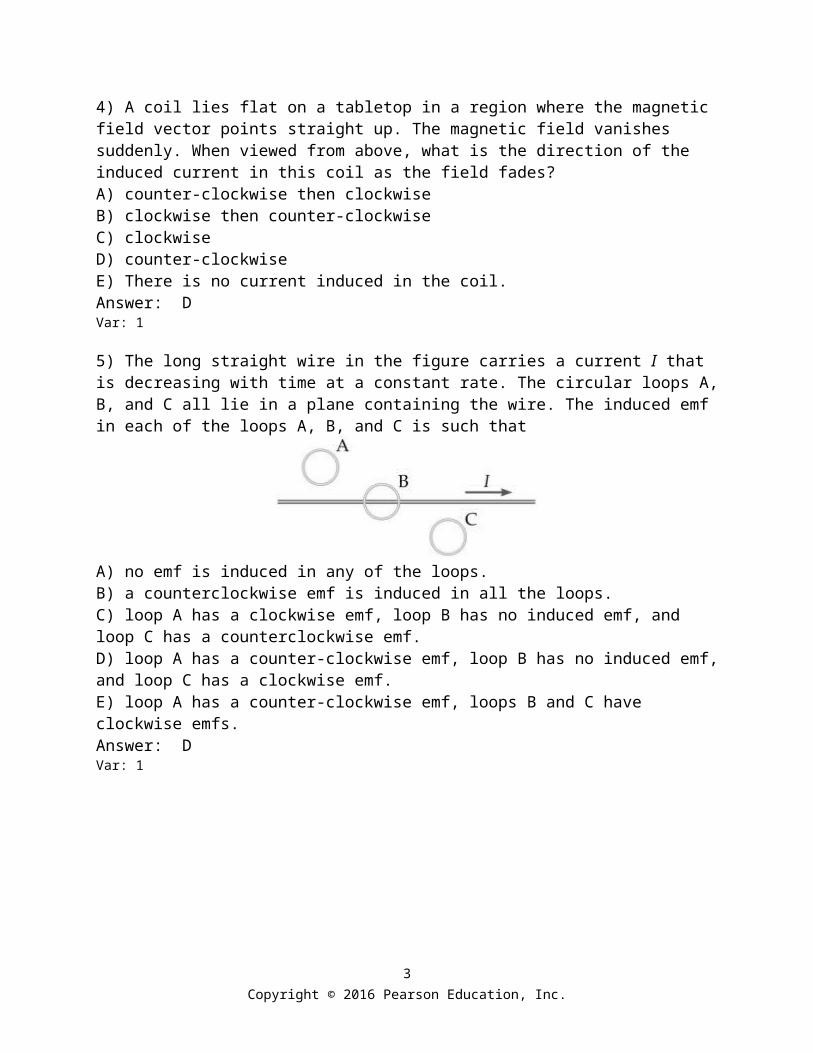
4) A coil lies flat on a tabletop in a region where the magnetic field vector points straight up. The magnetic field vanishes suddenly. When viewed from above, what is the direction of the induced current in this coil as the field fades?A) counter-clockwise then clockwiseB) clockwise then counter-clockwiseC) clockwiseD) counter-clockwiseE) There is no current induced in the coil.Answer: DVar: 1
5) The long straight wire in the figure carries a current I that is decreasing with time at a constant rate. The circular loops A, B, and C all lie in a plane containing the wire. The induced emf in each of the loops A, B, and C is such that
A) no emf is induced in any of the loops.B) a counterclockwise emf is induced in all the loops.C) loop A has a clockwise emf, loop B has no induced emf, and loop C has a counterclockwise emf.D) loop A has a counter-clockwise emf, loop B has no induced emf, and loop C has a clockwise emf.E) loop A has a counter-clockwise emf, loops B and C have clockwise emfs.Answer: DVar: 1
2Copyright © 2016 Pearson Education, Inc.
6) The figure shows a bar magnet moving vertically upward toward a horizontal coil. The poles of the bar magnets are labeled X and Y. As the bar magnet approaches the coil it induces an electric current in the direction indicated on the figure (counter-clockwise as viewed from above). What are the correct polarities of the magnet?
A) X is a south pole, Y is a north pole.B) X is a north pole, Y is a south pole.C) Both X and Y are north poles.D) Both X and Y are south poles.E) The polarities of the magnet cannot be determined from the information given.Answer: AVar: 1
7) A closed, circular loop has a counter-clockwise current flowing through it as viewed by a person on the right, as shown in the figure. If a second closed circular loop with the same radius approaches this loop with constant velocity along a common axis as shown, in what direction will a current flow in the approaching loop as viewed by the person on the right?
A) clockwiseB) counter-clockwiseC) No current will be induced because the velocity of approach is constant.Answer: AVar: 1
3Copyright © 2016 Pearson Education, Inc.

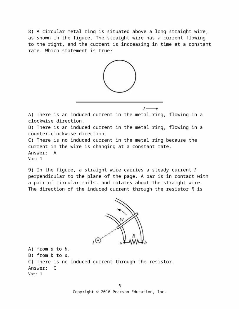
8) A circular metal ring is situated above a long straight wire, as shown in the figure. The straight wire has a current flowing to the right, and the current is increasing in time at a constant rate. Which statement is true?
A) There is an induced current in the metal ring, flowing in a clockwise direction.B) There is an induced current in the metal ring, flowing in a counter-clockwise direction.C) There is no induced current in the metal ring because the current in the wire is changing at a constant rate.Answer: AVar: 1
9) In the figure, a straight wire carries a steady current I perpendicular to the plane of the page. A bar is in contact with a pair of circular rails, and rotates about the straight wire. The direction of the induced current through the resistor R is
A) from a to b.B) from b to a.C) There is no induced current through the resistor.Answer: CVar: 1
4Copyright © 2016 Pearson Education, Inc.

10) In the figure, the inner loop carries a clockwise current I that is increasing. The resistor R is in the outer loop and both loops are in the same plane. The induced current through the resistor R is
A) from a to b.B) from b to a.C) There is no induced current through the resistor.Answer: AVar: 1
11) In the figure, a bar magnet moves away from the solenoid. The induced current through the resistor R is
A) from a to b.B) from b to a.C) There is no induced current through the resistor.Answer: AVar: 1
5Copyright © 2016 Pearson Education, Inc.
12) In the figure, a copper bar is in contact with a pair of parallel metal rails and is in motion with velocity ν. A uniform magnetic field is present pointing downward, as shown. The bar, the rails, and the resistor R are all in the same plane. The induced current through the resistor R is
A) from a to b.B) from b to a.C) There is no induced current through the resistor.Answer: CVar: 1
13) In the figure, two parallel wires carry currents of magnitude I in opposite directions. A rectangular loop is midway between the wires. The current I is decreasing with time. The induced current through the resistor R is
A) from a to b.B) from b to a.C) There is no induced current through the resistor.Answer: AVar: 1
6Copyright © 2016 Pearson Education, Inc.

14) A bar magnet is held vertically with its upper end a little bit below the center of a horizontal metal ring. The upper end of the magnet is its north pole, as shown in the figure. The bar magnet is now dropped. An observer views the ring from above its center. To this observer, how will the induced current in the ring behave as the magnet falls?
A) The current will flow clockwise and be increasing.B) The current will flow clockwise and be decreasing.C) The current will flow counter-clockwise and be increasing.D) The current will flow counter-clockwise and be decreasing.E) The induced current will be zero.Answer: DVar: 1
15) In the figure, two solenoids are side by side. The switch S, initially open, is closed. The induced current through the resistor R is
A) from a to b.B) from b to a.C) There is no induced current through the resistor.Answer: BVar: 1
7Copyright © 2016 Pearson Education, Inc.

16) In the figure, two solenoids are approaching each other with speed v as shown. The induced current through the resistor R is
A) from a to b.B) from b to a.C) There is no induced current through the resistor.Answer: AVar: 1
17) In the figure, a straight wire carries a current I. The wire passes through the center of a toroidal coil. If the current in the wire is quickly reduced to zero, the induced current through the resistor R is
A) from a to b.B) from b to a.C) There is no induced current through the resistor.Answer: BVar: 1
8Copyright © 2016 Pearson Education, Inc.

18) In the figure, a C-shaped conductor is in a uniform magnetic field B, which is increasing. The polarity of the induced emf in terminals X and Y is
A) X and Y are at the same potential.B) X is positive and Y is negative.C) X is negative and Y is positive.Answer: CVar: 1
19) The figure shows three metal coils labeled A, B, and C heading towards a region where a uniform static magnetic field exists. The coils move with the same constant velocity and all have the same resistance. Their relative sizes are indicated by the background grid. As they enter the magnetic field the coils will have an induced electric current in them. For which coil will the current be the greatest?
A) AB) BC) CD) The current is the same in all three cases since all the coils move with the same velocity.E) There is no induced current in any of the coils since they move at constant velocity.Answer: CVar: 1
9Copyright © 2016 Pearson Education, Inc.

20) A capacitor is charging in a simple RC circuit with a dc battery. Which one of the following statements about this capacitor is accurate?A) There is a magnetic field between the capacitor plates because charge travels between the plates by jumping from one plate to the other.B) There is no magnetic field between the capacitor plates because no charge travels between the plates.C) There is a magnetic field between the capacitor plates, even though no charge travels between them, because the magnetic flux between the plates is changing.D) There is a magnetic field between the capacitor plates, even though no charge travels between them, because the electric flux between the plates is changing.E) The magnetic field between the capacitor plates is increasing with time because the charge on the plates is increasing.Answer: DVar: 1
21) A resistor and an ideal inductor are connected in series to an ideal battery having a constant terminal voltage V0. At the moment contact is made with the battery, (a) the voltage across the resistor is
A) V0.B) V0/e.C) V0/2.D) zero.
(b) the voltage across the inductor isA) V0.B) V0/e.C) V0/2.D) zero.
Answer: (a) D (b) AVar: 1
22) Which of the following statements about inductors are correct? There may be more than one correct choice.A) When it is connected in a circuit, an inductor always resists having current flow through it.B) Inductors store energy by building up charge.C) When an inductor and a resistor are connected in series with a DC battery, the current in the circuit is reduced to zero in one time constant.D) An inductor always resists any change in the current through it.E) When an inductor and a resistor are connected in series with a DC battery, the current in the circuit is zero after a very long time.Answer: DVar: 1
10Copyright © 2016 Pearson Education, Inc.

27.2 Problems
1) A circular loop of radius 0.10 m is rotating in a uniform external magnetic field of 0.20 T. Find the magnetic flux through the loop due to the external field when the plane of the loop and the magnetic field vector are(a) parallel.(b) perpendicular.(c) at an angle of 30° with each other.Answer: (a) zero (b) 6.3 × 10⁻³ T ∙ m2 (c) 3.1 × 10⁻³ T ∙ m2 Var: 1
2) A 2.0-m long conducting wire is formed into a square and placed in the horizontal A uniform magnetic field is oriented above the horizontal with a strength of What is the magnetic flux through the square?A) 1.1 T ∙ m2
B) 1.9 T ∙ m2
C) 2.3 T ∙ m2
D) 18 T ∙ m2Answer: AVar: 10
3) A 200-loop coil of cross sectional area 8.5 cm2 lies in the plane of the page. An external magnetic field of 0.060 T is directed out of the plane of the page. The external field decreases to 0.020 T in 12 milliseconds.(a) What is the magnitude of the change in the external magnetic flux enclosed by the coil?(b) What is the magnitude of the average voltage induced in the coil as the external flux is changing?(c) If the coil has a resistance of 4.0 ohms, what is the magnitude of the average current in the coil?Answer: (a) 4.0 × 10⁻³ T ∙ m2 (b) 0.57 V (c) 0.14 AVar: 1
4) A ten-loop coil having an area of 0.23 m2 and a very large resistance is in a 0.047-T uniform magnetic field oriented so that the maximum flux goes through the coil. The coil is then rotated so that the flux through it goes to zero in 0.34 s. What is the magnitude of the average emf induced in the coil during the 0.34 s?A) 0.0032 VB) 0.00 VC) 0.032 VD) 0.32 VE) 1.0 VAnswer: DVar: 1
11Copyright © 2016 Pearson Education, Inc.

5) A uniform magnetic field is applied perpendicular to the plane of a 60-turn circular coil with a radius of 6.0 cm and a resistance of 0.60 Ω. If the magnetic field increases uniformly from 0.20 T to 1.8 T in 0.20 s, what is the magnitude of the emf induced in the coil?A) 7.2 VB) 5.4 VC) 9.2 VD) 12 VE) 16 VAnswer: BVar: 1
6) A loop of radius r = 3.0 cm is placed parallel to the xy-plane in a uniform magnetic field =
0.75 T . The resistance of the loop is 18 Ω. Starting at t = 0, the magnitude of the field decreases uniformly to zero in 0.15 seconds. What is the magnitude of the electric current produced in the loop during that time?A) 0.79 mAB) 3.9 mAC) 1.7 mAD) 2.1 mAE) 0.20 mAAnswer: AVar: 1
7) A circular coil of radius 5.0 cm and resistance 0.20 Ω is placed in a uniform magnetic field perpendicular to the plane of the coil. The magnitude of the field changes with time according to B = 0.50e-20t T. What is the magnitude of the current induced in the coil at the time t = 2.0 s?A) 1.3 mAB) 9.2 mAC) 7.5 mAD) 4.2 mAE) 2.6 mAAnswer: EVar: 1
8) A coil of 160 turns and area 0.20 m2 is placed with its axis parallel to a magnetic field of initial magnitude 0.40 T. The magnetic field changes uniformly from 0.40 T in the +x direction to 0.40 T in the -x direction in 2.0 s. If the resistance of the coil is 16 Ω, at what rate is power generated in the coil?A) 5.0 WB) 10 WC) 15 WD) 20 WE) 25 WAnswer: BVar: 1
12Copyright © 2016 Pearson Education, Inc.

9) A closed loop conductor that forms a circle with a radius of is located in a uniform but changing magnetic field. If the maximum emf induced in the loop is what is the maximum rate at which the magnetic field strength is changing if the magnetic field is oriented perpendicular to the plane in which the loop lies?A) 0.40 T/sB) 2.5 T/sC) 0.080 T/sD) 5.0 T/sAnswer: AVar: 9
10) As shown in the figure, a wire and a 10-Ω resistor are used to form a circuit in the shape of a square, 20 cm by 20 cm. A uniform but nonsteady magnetic field is directed into the plane of the circuit. The magnitude of the magnetic field is decreased from 1.50 T to 0.50 T in a time interval of 63 ms. The average induced current and its direction through the resistor, in this time interval, are closest to
A) 63 mA, from b to a.B) 38 mA, from b to a.C) 63 mA, from a to b.D) 38 mA, from a to b.E) 95 mA, from a to b.Answer: AVar: 50+
13Copyright © 2016 Pearson Education, Inc.

11) A conducting bar moves along frictionless conducting rails connected to a 4.00-Ω resistor as shown in the figure. The length of the bar is 1.60 m and a uniform magnetic field of 2.20 T is applied perpendicular to the paper pointing outward, as shown.(a) What is the applied force required to move the bar to the right with a constant speed of 6.00 m/s?(b) At what rate is energy dissipated in the 4.00 Ω resistor?
Answer: (a) 18.6 N (b) 112 WVar: 1
12) A conducting bar slides without friction on two parallel horizontal rails that are 50 cm apart and connected by a wire at one end. The resistance of the bar and the rails is constant and equal to 0.10 Ω. A uniform magnetic field is perpendicular to the plane of the rails. A 0.080-N force parallel to the rails is required to keep the bar moving at a constant speed of 0.50 m/s. What is the magnitude of the magnetic field?A) 0.10 TB) 0.25 TC) 0.36 TD) 0.54 TE) 0.93 TAnswer: BVar: 1
13) A 50-cm wire placed in an east-west direction is moved horizontally to the north with a speed of 2.0 m/s. The horizontal component of the earth's magnetic field at that location is 25 μT toward the north and the vertical component is 50μT downward. What is the emf induced between the ends of the wire?A) 10 µVB) 20 µVC) 30 µVD) 40 µVE) 50 µVAnswer: EVar: 1
14Copyright © 2016 Pearson Education, Inc.

14) For a long ideal solenoid having a circular cross-section, the magnetic field strength within the solenoid is given by the equation B(t) = 5.0t T, where t is time in seconds. If the induced electric field outside the solenoid is 1.1 V/m at a distance of 2.0 m from the axis of the solenoid, find the radius of the solenoid.A) 0.30 mB) 77 mC) 0.94 mD) 9.0 mAnswer: CVar: 1
15) The coil in a 60-Hz ac generator has 125 turns, each having an area of 3.0 × 10⁻² m2 and is rotated in a uniform 0.12-T magnetic field. What is the peak output voltage of this generator?A) 170 VB) 120 VC) 200 VD) 110 VE) 220 VAnswer: AVar: 1
16) Suppose that you wish to construct a simple ac generator having an output of 12 V maximum when rotated at 60 Hz. A uniform magnetic field of 0.050 T is available. If the area of the rotating coil is 100 cm2, how many turns do you need?A) 8B) 16C) 32D) 64E) 128Answer: DVar: 1
17) You are designing a generator to have a maximum emf of 8.0 V. If the generator coil has 200 turns and a cross-sectional area of 0.030 m2, what should be the frequency of the generator in a uniform magnetic field of 0.030 T?A) 7.1 HzB) 7.5 HzC) 8.0 HzD) 22 HzE) 44 HzAnswer: AVar: 1
15Copyright © 2016 Pearson Education, Inc.

18) A rectangular coil having N turns and measuring 15 cm by 25 cm is rotating in a uniform 1.6-T magnetic field with a frequency of 75 Hz. The rotation axis is perpendicular to the direction of the field. If the coil develops a sinusoidal emf of maximum value 56.9 V, what is the value of N?A) 2B) 4C) 6D) 8E) 10Answer: AVar: 1
19) Wire is wound on a square frame, 30 cm by 30 cm, to form a coil of 7 turns. The frame is mounted on a horizontal shaft through its center (perpendicular to the plane of the diagram), as shown in the figure. The coil is in clockwise rotation, with a period of 0.060 s. A uniform, horizontal, magnetic field of magnitude 0.40 T is present. At a given instant, the plane of the coil forms a 60° angle with the horizontal, as shown. At that instant, what is the magnitude of the emf induced in the coil?
A) 13 VB) 23 VC) 2.1 VD) 3.6 VE) 26 VAnswer: AVar: 1
20) What is the self-inductance of a solenoid 30.0 cm long having 100 turns of wire and a cross-sectional area of 1.00 × 10⁻⁴ m2? (μ0 = 4π × 10-7 T ∙ m/A)A) 4.19 nHB) 4.19 pHC) 4.19 µHD) 4.19 mHE) 4.19 HAnswer: CVar: 1
16Copyright © 2016 Pearson Education, Inc.

21) At what rate would the current in a 100-mH inductor have to change to induce an emf of 1000 V in the inductor?A) 100 A/sB) 1 A/sC) 1000 A/sD) 10,000 A/sE) 10 A/sAnswer: DVar: 1
22) An inductor has a current I(t) = (0.500 A) cos[(275 )t] flowing through it. If the maximum emf across the inductor is equal to 0.500 V, what is the self-inductance of the inductor?A) 4.37 mHB) 3.64 mHC) 2.75 mHD) 0.73 mHE) 1.43 mHAnswer: BVar: 5
23) In the figure, the current in a solenoid having no appreciable resistance is flowing from b to a and is decreasing at a rate of 9.6 A/s. The self-induced emf in the solenoid is found to be 8.4 V.
(a) What is the self-inductance of the solenoid?(b) Which point, a or b is at higher potential?Answer: (a) 0.88 H (b) point aVar: 50+
24) An insulated wire of diameter 1.0 mm and negligible resistance is wrapped tightly around a cylindrical core of radius 5.0 cm and length 30 cm to build a solenoid. What is the energy stored in this solenoid when a current I = 0.20 A flows through it? (μ0 = 4π × 10-7 T ∙ m/A)
A) 1.2 × 10⁻⁴ JB) 9.6 × 10⁻⁴ JC) 4.8 × 10⁻⁴ JD) 2.4 × 10⁻⁴ JE) 5.9 × 10⁻⁵ JAnswer: EVar: 1
17Copyright © 2016 Pearson Education, Inc.

25) A solenoid of length 0.700 m having a circular cross-section of radius 5.00 cm stores 6.00 µJ of energy when a 0.400-A current runs through it. What is the winding density of the solenoid? (μ0 = 4π × 10-7 T ∙ m/A)A) 865 turns/mB) 472 turns/mC) 1080 turns/mD) 104 turns/mE) 327 turns/mAnswer: DVar: 1
26) At a certain instant the current flowing through a 5.0-H inductor is 3.0 A. If the energy in the inductor at this instant is increasing at a rate of 3.0 J/s, how fast is the current changing?A) 0.20 A/sB) 0.40 A/sC) 0.10 A/sD) 0.80 A/sAnswer: AVar: 1
27) How much energy is stored in a room 3.0 m by 4.0 m by 2.4 m due to the earth's magnetic field with a strength of 5.0 × 10⁻⁵ T? (μ0 = 4π × 10-7 T ∙ m/A)A) 570 mJ.B) 29 mJ.C) 10 mJ.D) 100 mJ.E) 575 mJ.Answer: BVar: 1
28) What is the energy density in the magnetic field 25 cm from a long straight wire carrying a current of 12 A? (μ0 = 4π × 10-7 T ∙ m/A)
A) 7.3 × 10⁻⁵ J/m3
B) 3.7 × 10⁻⁵ J/m3
C) 3.6 × 10⁻⁴ J/m3
D) 1.2 × 10⁻⁴ J/m3E) The density cannot be determined without knowing the volume.Answer: BVar: 1
29) A series circuit consists of a 0.55-H inductor with internal resistance of 8.0 Ω connected in series with a 4.0-Ω resistor, an open switch, and an ideal 12-V battery.(a) When the switch is closed, what is the initial current through the 4.0-Ω resistor?(b) What is the current through the 4.0-Ω resistor a very long time after the switch is closed?Answer: (a) 0.00 A (b) 1.0 AVar: 1
18Copyright © 2016 Pearson Education, Inc.
30) A 45-mH ideal inductor is connected in series with a 60-Ω resistor through an ideal 15-V DC power supply and an open switch. If the switch is closed at time t = 0 s, what is the current 7.0 ms later?A) 250 mAB) 650 mAC) 550 mAD) 280 mAE) 850 mAAnswer: AVar: 5
31) A series LR circuit consists of a 2.0-H inductor with negligible internal resistance, a 100-ohm resistor, an open switch, and a 9.0-V ideal power source. After the switch is closed, what is the maximum power delivered by the power supply?A) 0.40 WB) 81 WC) 0.090 WD) 8.1 WE) 0.81 WAnswer: EVar: 1
32) What resistance should be added in series with a 3.0-H inductor to complete an LR circuit with a time constant of ?A) 0.75 k ΩB) 12 ΩC) 0.75 ΩD) 2.5 ΩAnswer: AVar: 28
33) A series LR circuit contains an emf source of having no internal resistance, a resistor, a inductor having no appreciable resistance, and a switch. If the emf across the inductor is of its maximum value after the switch is closed, what is the resistance of the resistor?
A) 14 ΩB) 1.9 ΩC) 1.5 ΩD) 5.0 ΩAnswer: BVar: 50+
19Copyright © 2016 Pearson Education, Inc.

34) An LR circuit contains an ideal 60-V battery, a 42-H inductor having no resistance, a 24-Ω resistor, and a switch S, all in series. Initially, the switch is open and has been open for a very long time. At time t = 0 s, the switch is suddenly closed. How long after closing the switch will the potential difference across the inductor be 24 V?A) 1.6 sB) 1.4 sC) 1.8 sD) 1.9 sE) 2.1 sAnswer: AVar: 1
35) An LR circuit contains an ideal 60-V battery, a 51-H inductor having no resistance, a 21-Ω resistor, and a switch S, all in series. Initially, the switch is open and has been open for a very long time. At time t = 0 s, the switch is suddenly closed. When the voltage across the resistor is equal to the voltage across the inductor, what is the current in the circuit?A) 1.4 AB) 0.57 AC) 1.1 AD) 0.86 AE) 1.7 AAnswer: AVar: 1
36) For the circuit shown in the figure, the inductors have no appreciable resistance and the switch has been open for a very long time.
(a) The instant after closing the switch, what is the current through the 60.0-Ω resistor?(b) The instant after closing the switch, what is the potential difference across the 15.0-mH inductor?(c) After the switch has been closed and left closed for a very long time, what is the potential drop across the 60.0-Ω resistor?Answer: (a) 1.43 A (b) 85.7 V (c) 0.00 VVar: 1
20Copyright © 2016 Pearson Education, Inc.

37) For the circuit shown in the figure, the switch has been open for a very long time.
(a) What is the potential drop across the 15.0-mH inductor just after closing the switch?(b) What is the potential drop across the 70.0-µF capacitor after the switch has been closed for a very long time?Answer: (a) 150.0 V (b) 133 VVar: 1
38) An ideal solenoid is 18.5 cm long, has a circular cross-section 2.20 cm in diameter, and contains 545 equally spaced thin windings. This solenoid is connected in a series circuit with an open switch, a 15.0-Ω resistor, and a battery of internal resistance 5.00 Ω and open-circuit terminal voltage of 25.0 V. (μ0 = 4π × 10-7 T ∙ m/A)(a) What is the maximum amount of energy that the solenoid will store after closing the switch?(b) How long after closing the switch will it take for the stored energy in the solenoid to reach one-half of its maximum value?Answer: (a) 0.599 mJ (b) 47.1 µsVar: 1
39) Consider the circuit shown in the figure. The battery has emf ε = 25 volts and negligible internal resistance. The inductance is and the resistances are R1 = 12 Ω and R2 = 9.0 Ω. Initially the switch S is open and no currents flow. Then the switch is closed.
(a) What is the current in the resistor R1 just after the switch is closed?(b) After leaving the switch closed for a very long time, it is opened again. Just after it is opened, what is the current in R1?Answer: (a) 2.1 A (b) 2.8 AVar: 50+
21Copyright © 2016 Pearson Education, Inc.