wmkk - kl international / sepang - AIP-DCA - CIVIL AVIATIONaip.dca.gov.my/aip...
22
AIP MALAYSIA DEPARTMENT OF CIVIL AVIATION MALAYSIA WMKK AD 2 - 1 WMKK AD 2.1 AERODROME LOCATION INDICATOR AND NAME WMKK - KL INTERNATIONAL / SEPANG WMKK AD 2.2 AERODROME GEOGRAPHICAL AND ADMINISTRATIVE DATA 1 ARP coordinates and site at AD LAT 024436 N LONG 1014153E Site: RWY 14R threshold centerline. 2 Direction and distance from city Bearing 180 deg/43 KM from Kuala Lumpur. 3 Elevation / Reference temperature [WGS84] 21.15M (70 feet) / 32° C 4 Geoid Undulation (ARP) -1.548 M 5 MAG VAR / Annual change 06 min 00 sec West (2012) 6 AD Administration, address, telephone, telefax, telex, AFS Operator : ATC Services : Malaysia Airports Berhad. Malaysia Airports (Sepang) Sdn. Bhd. KL International Airport 64000 KLIA Selangor Darul Ehsan. Tel : 603 - 87769106 Fax : 603 - 89265012 Department of Civil Aviation Malaysia Air Traffic Control Tower Complex KL International Airport 64000 KLIA Selangor Darul Ehsan Tel : 603 - 87874118 (General Office) 603 - 87874230 (ATC Tower) Fax : 603 - 89265989 (General Office) 603 - 89265758 (ATC Tower) AFS/AFTN : WMKKZTZX 7 Types of traffic permitted (IFR/VFR) IFR category : VFR category : Approved international and domestic flights. Approved helicopter operations. 8 Remarks Nil WMKK AD 2.3 OPERATIONAL HOURS 1 AD Administration H24 2 Customs and immigration H24 3 Health and sanitation H24 4 AIS Briefing Office H24 5 ATS Reporting Office H24 6 MET Briefing Office H24 7 ATS H24 8 Fuelling PETRONAS Refuelling : H24 SHELL Refuelling : H24 ESSO Refuelling : H24 9 Handling Prior arrangement. 10 Security H24 11 De-icing Not available 12 Remarks Nil 08 MAR 2012 AIP AMDT 1/2012
-
Upload
nguyenkiet -
Category
Documents
-
view
215 -
download
3
Transcript of wmkk - kl international / sepang - AIP-DCA - CIVIL AVIATIONaip.dca.gov.my/aip...

AIP MALAYSIA
DEPARTMENT OF CIVIL AVIATION MALAYSIA
WMKK AD 2 - 1
WMKK AD 2.1 AERODROME LOCATION INDICATOR AND NAME
WMKK - KL INTERNATIONAL / SEPANG
WMKK AD 2.2 AERODROME GEOGRAPHICAL AND ADMINISTRATIVE DATA
1 ARP coordinates and site at AD LAT 024436 N LONG 1014153ESite: RWY 14R threshold centerline.
2 Direction and distance from city Bearing 180 deg/43 KM from Kuala Lumpur.
3 Elevation / Reference temperature [WGS84] 21.15M (70 feet) / 32° C4 Geoid Undulation (ARP) -1.548 M5 MAG VAR / Annual change 06 min 00 sec West (2012)6 AD Administration, address, telephone, telefax, telex, AFS
Operator :
ATC Services :
Malaysia Airports Berhad.Malaysia Airports (Sepang) Sdn. Bhd.KL International Airport64000 KLIASelangor Darul Ehsan.Tel : 603 - 87769106Fax : 603 - 89265012
Department of Civil Aviation MalaysiaAir Traffic Control Tower ComplexKL International Airport64000 KLIASelangor Darul EhsanTel : 603 - 87874118 (General Office) 603 - 87874230 (ATC Tower)Fax : 603 - 89265989 (General Office) 603 - 89265758 (ATC Tower)AFS/AFTN : WMKKZTZX
7 Types of traffic permitted (IFR/VFR) IFR category :
VFR category :
Approved international and domestic flights.
Approved helicopter operations.
8 Remarks Nil
WMKK AD 2.3 OPERATIONAL HOURS
1 AD Administration H242 Customs and immigration H243 Health and sanitation H244 AIS Briefing Office H24
5 ATS Reporting Office H246 MET Briefing Office H247 ATS H248 Fuelling PETRONAS Refuelling : H24
SHELL Refuelling : H24ESSO Refuelling : H24
9 Handling Prior arrangement.10 Security H2411 De-icing Not available12 Remarks Nil
08 MAR 2012 AIP AMDT 1/2012
AIP MALAYSIA
DEPARTMENT OF CIVIL AVIATION MALAYSIA
WMKK AD 2 - 2
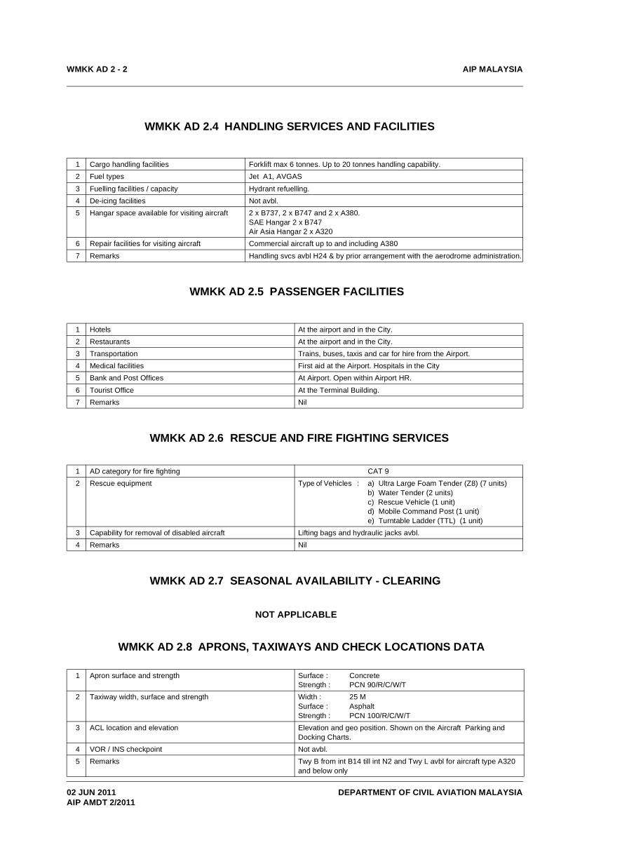
WMKK AD 2.4 HANDLING SERVICES AND FACILITIES
1 Cargo handling facilities Forklift max 6 tonnes. Up to 20 tonnes handling capability.2 Fuel types Jet A1, AVGAS
3 Fuelling facilities / capacity Hydrant refuelling.4 De-icing facilities Not avbl.5 Hangar space available for visiting aircraft 2 x B737, 2 x B747 and 2 x A380.
SAE Hangar 2 x B747 Air Asia Hangar 2 x A320
6 Repair facilities for visiting aircraft Commercial aircraft up to and including A380
7 Remarks Handling svcs avbl H24 & by prior arrangement with the aerodrome administration.
WMKK AD 2.5 PASSENGER FACILITIES
1 Hotels At the airport and in the City.2 Restaurants At the airport and in the City.3 Transportation Trains, buses, taxis and car for hire from the Airport.4 Medical facilities First aid at the Airport. Hospitals in the City5 Bank and Post Offices At Airport. Open within Airport HR.
6 Tourist Office At the Terminal Building.7 Remarks Nil
WMKK AD 2.6 RESCUE AND FIRE FIGHTING SERVICES
1 AD category for fire fighting CAT 92 Rescue equipment Type of Vehicles : a) Ultra Large Foam Tender (Z8) (7 units)
b) Water Tender (2 units)c) Rescue Vehicle (1 unit)d) Mobile Command Post (1 unit)e) Turntable Ladder (TTL) (1 unit)
3 Capability for removal of disabled aircraft Lifting bags and hydraulic jacks avbl.4 Remarks Nil
WMKK AD 2.7 SEASONAL AVAILABILITY - CLEARING
NOT APPLICABLE
WMKK AD 2.8 APRONS, TAXIWAYS AND CHECK LOCATIONS DATA
1 Apron surface and strength Surface :Strength :
ConcretePCN 90/R/C/W/T
2 Taxiway width, surface and strength Width :Surface :Strength :
25 M AsphaltPCN 100/R/C/W/T
3 ACL location and elevation Elevation and geo position. Shown on the Aircraft Parking and Docking Charts.
4 VOR / INS checkpoint Not avbl. 5 Remarks Twy B from int B14 till int N2 and Twy L avbl for aircraft type A320
and below only
02 JUN 2011AIP AMDT 2/2011

AIP MALAYSIA
DEPARTMENT OF CIVIL AVIATION MALAYSIA
WMKK AD 2 - 3
WMKK AD 2.9 SURFACE MOVEMENT GUIDANCE AND CONTROL SYSTEM AND MARKINGS
1 Use of aircraft stand ID signs, TWY guide lines and visual docking / parking guidance system of aircraft stands
Taxiing guidance signs at all intersections with TWY and RWY and at all holding positions. Guide lines at apron. Nose - in guidance at aircraft stands.
2 RWY and TWY markings and LGT RWY : Designation, THR, TDZ, Centreline, Edge, RWY End as appropriate, marked and lighted.TWY : Centreline, holding positions at all TWY/RWY intersections, marked and lighted.
3 Stop bars Stop bars on all Rwy / Twy intersections.4 Remarks Surface movement surveillance radar in use.
WMKK AD 2.10 AERODROME OBSTACLES
In APCH/TKOF areas In circling area and at AD Remarks1 2 3
RWY / Area effected
Obstacles TypeElevation
Markings / LGT
Coordinates Obstacles TypeElevation
Markings / LGT
Coordinates
a b c a b14R/APCH 32L/TKOF
LLZ antennas: 19.75 M Red/Red obstruction lights
024443.7N 1014147.4E
Glide path aerial 32.15 M Red/whiteRed obstruction lights
IWDI22.60 M
024425.6N 1014154.8E
024432.1N 1014158.7E
Nil
32L/APCH 14R/TKOF
LLZ antennas 17.64 M Red/Red obstruction lights
AWOS No.7 22.3M
AWOS No.8 22.1 M
AWOS NO.9 23.5 M
024241.7N 1014309.2E
024254.7N 1014255.5E
024339.7N 1014225.6E
024424.2N 1014155.8E
Glide path aerial 30.90 M Red/white Red obstruction lights
IWDI 20.95 M
Hill - Bukit Lada 110.048 M AMSLRed obstruction lights
Hill - Bukit Sungai Lanau 100.890 M AMSLRed obstruction lights
Power Plant - 15 KM South of THR RWY 32 525 FT AMSL Marked and lighted at night.
024254.0N 1014256.7E
024256.2N 1014255.9E
024232.7N 1014356.6E
024158.1N 1014304.7E
023524.6N 1014327.9E
Nil
20 NOV 2008AIP AMDT 4/2008

AIP MALAYSIA
DEPARTMENT OF CIVIL AVIATION MALAYSIA
WMKK AD 2 - 4
14L/APCH 32R/TKOF
LLZ antennas 19.4 M Red/Red obstruction lights
AWOS No.2 24.9 M
AWOS No.3 25.3 M
AWOS No.4 27.6 M
024648.7N 1014202.5E
024635.0N 1014216.4E
024550.5N 1014245.7E
024506.0N 1014316.1E
Glide path aerial 32.8 M Red/white Red obstruction lights
IWDI 23.65 M
Control tower 141.45 M Red obstruction lights
Radar sensor 69.8 M Red obstruction lights
024636.6N 1014215.3E
024638.9N 1014215.8E
024525.5N 1014208.8E
024630.0N 1014124.0E
Nil
32R/APCH 14L/TKOF
LLZ antennas 24.94 M Red/Red obstruction lights
024445.3N 1014325.3E
Glide path aerial 36.2 M Red/white Red obstruction light
IWDI 26.56 M
024504.9N 1014316.8E
024457.9N 1014313.4E
Nil
WMKK AD 2.11 METEOROLOGICAL INFORMATION PROVIDED
1 Associated MET Office SEPANG
2 Hours of serviceMET Office outside hours
H24
3 Office responsible for TAF preparation Periods of validity
KL International Airport Meteorological Office30
4 Type of landing forecastInterval of issuance
TRENDHalf hourly
5 Briefing / consultation provided Provided6 Flight documentation
Language(s) usedCharts, Tabular Form and Abbreviated Plain Language TextEnglish
7 Charts and other information available for briefing or consultation
Flight Level Wind/Temp FL50, FL100, FL140, FL180, FL250, FL320 and FL360, SIGWX, Volcanic Ash/Tropical Cyclone Advisory, SIGMET, AIRMET, Aerodrome Warning, METAR Bulletin, TAFOR Bulletin, WMKK Take-Off Data, Area QNH for Kuala Lumpur FIR, Radar and Satellite Pictures.
8 Supplementary equipment available for providing information Doppler Weather Radar and Self-Briefing Terminals9 ATS units provided with information Subang ATSC.
KL International Airport TWRs.KL International Airport Pilot Briefing Office.Subang Pilot Briefing Office.
10 Additional information Tel: +603 - 87872388Fax: +603 - 87871020 / +603 - 87871019
In APCH/TKOF areas In circling area and at AD Remarks1 2 3
RWY / Area effected
Obstacles TypeElevation
Markings / LGT
Coordinates Obstacles TypeElevation
Markings / LGT
Coordinates
a b c a b
15 NOV 2012AIP AMDT 3/2012

AIP MALAYSIA
DEPARTMENT OF CIVIL AVIATION MALAYSIA
WMKK AD 2 - 5
WMKK AD 2.12 RUNWAY PHYSICAL CHARACTERISTICS
DesignationRWY NR
TRUE andMAG BRG
Dimensions ofRWY (M)
Strength (PCN)Surface of RWY
and SWY
THRCoordinates
THR elevation andhighest elevation of TDZof precision APP RWY
1 2 3 4 5 6
14R 146° T 4000 x 60 90/R/C/W/T - 241M conc100/F/C/W/T - 3519M flex 240M conc
024435.84N 1014152.63E
THR : 16.50M 54.13 FT
32L 326° T 4000 x 60 90/R/C/W/T - 241M conc100/F/C/W/T - 3519M flex 297M conc
024247.86N 1014305.03E
THR : 14.50M 47.57 FT
14L 146° T 4019 x 60 90/R/C/W/T - 241M conc100/F/C/W/T - 3537M flex 346M conc
024642.52N 1014206.67E
THR : 16.6M 54.46 FT
32R 326° T 4019 x 60 90/R/C/W/T - 241M conc100/F/C/W/T - 3537M flex 241M conc
024454.03N 1014319.41E
THR : 21.15M 69.39 FT
Slope ofRWY - SWY
SWY Dimensions(M)
CWY Dimensions(M)
Strips Dimensions(M)
OFZ Remarks
7 8 9 10 11 12
0.05% Nil Nil 4120 x 300 Provided RESA RWY 14R : 120M X 120M
0.05% Nil Nil 4120 x 300 Provided RESA RWY 32L :176M X 120M
0.12% Nil Nil 4139 x 300 Provided RESA RWY 14L :225M X 120M
0.12% Nil Nil 4139 x 300 Provided RESA RWY 32R :120M X 120M
02 JUN 2011AIP AMDT 2/2011
AIP MALAYSIA
DEPARTMENT OF CIVIL AVIATION MALAYSIA
WMKK AD 2 - 6
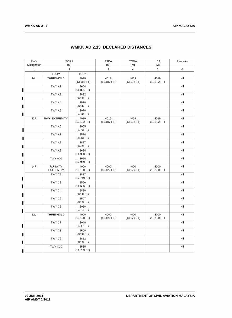
WMKK AD 2.13 DECLARED DISTANCES
RWYDesignator
TORA(M)
ASDA (M)
TODA(M)
LDA(M)
Remarks
1 2 3 4 5 6FROM TORA
14L THRESHOLD 4019 (13,182 FT)
4019(13,182 FT)
4019(13,182 FT)
4019(13,182 FT)
Nil
TWY A2 3604(11,821 FT)
Nil
TWY A3 2832(9289 FT)
Nil
TWY A4 2520(8266 FT)
Nil
TWY A5 2070(6790 FT)
Nil
32R RWY EXTREMITY 4019(13,182 FT)
4019(13,182 FT)
4019(13,182 FT)
4019(13,182 FT)
Nil
TWY A6 2065(6773 FT)
Nil
TWY A7 2574(8443 FT)
Nil
TWY A8 2887(9469 FT)
Nil
TWY A9 3634(11,920 FT)
Nil
TWY A10 3954(12,969 FT)
Nil
14R RUNWAY EXTREMITY
4000(13,120 FT)
4000(13,120 FT)
4000(13,120 FT)
4000(13,120 FT)
Nil
TWY C2 3887(12,749 FT)
Nil
TWY C3 3566(11,696 FT)
Nil
TWY C4 2820(9250 FT)
Nil
TWY C5 2507(8223 FT)
Nil
TWY C6 2050(6724 FT)
Nil
32L THRESHOLD 4000(13,120 FT)
4000(13,120 FT)
4000(13,120 FT)
4000(13,120 FT)
Nil
TWY C7 2048(6717 FT)
Nil
TWY C8 2500(8200 FT)
Nil
TWY C9 2812(9223 FT)
Nil
TWY C10 3585(11,759 FT)
Nil
02 JUN 2011AIP AMDT 2/2011

AIP MALAYSIA
DEPARTMENT OF CIVIL AVIATION MALAYSIA
WMKK AD 2 - 7
WMKK AD 2.14 APPROACH AND RUNWAY LIGHTING
RWYDesignator
APCH LGT type LEN
INTST
THR LGT colour WBAR
VASIS(MEHT)
PAPI
TDZ LGT LEN (M)
RWY CentreLine Lgt
Length, spacing, colour INTST
RWY edge LGT LEN Spacing, colour INTST
RWY End LGT
colour WBAR
SWY LGT LEN
(M) colour
Remarks
1 2 3 4 5 6 7 8 9 10
14L CAT II 900 M
LIH Sequence
Flash Lights from 900M to
300M
Green PAPI Left/Right
3° 21.5
900 4019M, 15M White: 0 -3119M Red/White: 3119M - 3719M Red: 3719M - 4019M, LIH
4019M, 60M White: 0 -3419M Yellow: 3419M - 4019M,LIH
Red Nil Nil
32R CAT II 900 M
LIH Sequence
Flash Lights from 900M to
300M
Green PAPI Left/Right
3°21.5
900 4019M, 15M White: 0 - 3224MRed/White: 3224M - 3824M Red: 3824M - 4019M,LIH
4019M, 60M Red: 0 - 47M White: 47M - 3524MYellow: 3524M - 4019M, LIH
Red Nil Nil
14R CAT II 900 M
LIH Sequence
Flash Lights from 900M to
300M
Green PAPI Left/Right
3° 21.5
900 4000M, 15M White: 0 -3156M Red/White: 3156M - 3756M Red: 3756M - 4000M, LIH
4000M, 60M White: 0 -3456M Yellow: 3456M - 4000M,LIH
Red Nil Nil
32L CAT II 900 M
LIH Sequence
Flash Lights from 900M to
300M
Green PAPI Left/Right
3° 21.5
900 4000M, 15M White: 0 -3100M Red/White: 3100M - 3700M Red: 3700M - 4000M, LIH
4000M, 60M White: 0 -3400M Yellow: 3400M - 4000M,LIH
Red Nil Nil
20 NOV 2008AIP AMDT 4/2008

AIP MALAYSIA
DEPARTMENT OF CIVIL AVIATION MALAYSIA
WMKK AD 2 - 8
WMKK AD 2.15 OTHER LIGHTING, SECONDARY POWER SUPPLY
1 ABN / IBN location, characteristics andhours of operation
Nil
2 LDI location and LGTAnemometer location and LGT
LDI : NilIlluminated Wind Direction Indicator (IWDI).14L : 345M from THR at Left; Lighted32R : 200M from THR at Left; Lighted14R : 200M from THR at left; Lighted32L : 310M from THR at Left; Lighted
3 TWY edge and centre line lighting Edge : At all TWY curves and filletsCentre Line : At all TWY and taxilanes.Clearance Bar : At all TWY intersections.
4 Secondary power supply / switch-over time Secondary power supply to all lighting:Switch over time:1sec - All Runway, Approach, Stop Bar and PAPI15 sec - All TWY Edge, Centre Line, Signs, Obstacles and IWDI.
5 Remarks Stop Bar : At all TWY entering RWY.
WMKK AD 2.16 HELICOPTER LANDING AREA
1 Coordinates TLOF or THR of FATO 024550.68N 1014204.20E2 TLOF and/or FATO elevation M/FT 22.10M/72.51 FT.
3 TLOF and FATO area dimension, surface, strength, marking Rectangle, 30M x 30M, Asphalt, 30 Tonnes White edges and white letter H
4 True and MAG BRG of FATO True North Bearing - 61 45 00 from ARG X-axisMagnetic Bearing - 10.69min West of True North.
5 Declared distance available Nil6 APP and FATO lighting Nil
7 Remarks Ground taxy to apron
WMKK AD 2.17 ATS AIRSPACE
1 Designation and lateral limits Kuala Lumpur CTRSemi circle of 15 NM radius centred on Kuala Lumpur (VKL) DVOR/DME (024328N 1014417E) fm 024450N 1015913E clockwise to 023709N 1013041E thence a straight line to 030134N1011921E thence a semicircle of 15 NM radius centred on SAAS Subang ARP (030752N 1013253E) clockwise to 032245N 1013454E thence a straight line to 032133N 1014406E thence a semi circle of 15 NM radius centred on Simpang ARP (030641N 1014209E) clockwise to 030803N 1015706E thence a straight line to 024450N 1015913E.
2 Vertical limits SFC to 4000 FT AMSL .3 Airspace classification Class C (except for WMR 418/236 which is G)4 ATS unit callsign
Language(s)Lumpur Approach North, Lumpur Approach South, Lumpur Director. Lumpur Tower.English
5 Transition altitude 11000 FT.6 Remarks Nil
19 NOV 2009AIP AMDT 4/2009

AIP MALAYSIA
DEPARTMENT OF CIVIL AVIATION MALAYSIA
WMKK AD 2 - 9
WMKK AD 2.18 ATS COMMUNICATION FACILITIES
ServiceDesignation
Callsign Frequency Hours ofoperation
Remarks
1 2 3 4 5
APP LUMPUR APPROACH NORTH
124.200 MHZ230.000 MHZ
H24
-
APP LUMPUR APPROACH SOUTH
119.450 MHZ232.200 MHZ
-
APP LUMPUR DIRECTOR 125.100 MHZ -
APP 121.250 MHZ Spare position and frequency
AERODROME CONTROL
LUMPUR TOWER 118.800 MHZ229.000 MHZ
RWY 14L/32R
AERODROME CONTROL
LUMPUR TOWER 118.500 MHZ229.000 MHZ
RWY 14R/32L
SURFACE MOVEMENT CONTROL
LUMPUR GROUND 121.650 MHZ229.000 MHZ
TWY associated with RWY 14L/32R
SURFACE MOVEMENT CONTROL
LUMPUR GROUND 121.800 MHZ 229.000 MHZ
TWY associated with RWY 14R/32L and Cargo South (CS)
GROUND MOVEMENT CONTROL
LUMPUR GROUND 122.150 MHZ Main Terminals aprons
GROUNDMOVEMENT CONTROL
LUMPUR GROUND 122.850 MHZ North and West Satellite Terminal aprons
GROUND MOVEMENT CONTROL
LUMPUR GROUND 122.275 MHZ East and South Satellite Terminal
GROUND MOVEMENT CONTROL
LUMPUR GROUND 123.25 MHZ Cargo East, North and West
ACD LUMPUR DELIVERY 126.000 MHZ Airways clearance, SSR code allocation and departure slot time
ATIS LUMPUR TERMINAL INFORMATION
126.450 MHZ Synthesised voice broadcast
15 MAR 2007 AIP AMDT 1/2007

AIP MALAYSIA
DEPARTMENT OF CIVIL AVIATION MALAYSIA
WMKK AD 2 - 10
WMKK AD 2.19 RADIO NAVIGATION AND LANDING AIDS
Type of aidCAT of ILS
ID Frequency Hours ofoperation
Site TX antenna coordinates Elevation of DME transmitting antenna
Remarks
1 2 3 4 5 6 7
DVOR VKL 116.100 MHZ
H24
024328N 1014417E - Nil
DME VKL CH 108X 024328N 1014417E 79.65 M Nil
ILS CAT I IEL 108.500 MHZ GP : 024636.6N 1014215.3ELLZ : 024445.3N 1014325.3E
- 14L
DME IEL CH 22X 024636.6N 1014215.3E 18 M 14L
ILS CAT I IER 109.100 MHZ GP : 024504.9N 1014316.8ELLZ : 024648.7N 1014202.5E
- 32R
DME IER CH 28X 024504.9N 1014316.8E 21 M 32R
ILS CAT I IWR 110.700 MHZ GP : 024425.55N 1014154.81ELLZ : 024241.66N 1014309.19E
- 14R
DME IWR CH 44X 024425.55N 1014154.81E 23.97 M 14R
ILS CAT I IWL 111.900 MHZ GP : 024254.00N 1014256.69ELLZ : 024443.6N 1014147.43E
- 32L
DME IWL CH 56X 024254.00N 1014256.69E 24.77 M 32L
17 JUN 1999

AIP MALAYSIA
DEPARTMENT OF CIVIL AVIATION MALAYSIA
WMKK AD 2 - 11
1 Start Up And Push Back
1.1 Air traffic control will authorise the initiation of engine start up and aircraft push back in order to regulate the movement of aircraft with respect to other aircraft on the apron edge and apron centre lane taxiways.
1.2 The pilots-in-command of all aircraft require clearance from air traffic control for both engine start up and push back. All departing aircraft shall contact LUMPUR DELIVERY for ATC clearance 5 minutes before engine start.
1.3 When air traffic control provides the pilot-in-command with approval to push back, this approval may also contain an expectation to exit the apron via a specified apron taxiway if the intended taxiing route is not a standard taxiing route. Whether complying with a standard taxiing route or a special taxiing route, the pilot-in-command shall ensure that the direction of push back enables the aircraft to taxi via the specified apron access taxiway.
1.4 During engine start up, it shall be the responsibility of the pilot-in-command and the aircraft marshaller to ensure that the area of the blast cone is clear.
1.5 During aircraft push back, it shall be the responsibility of the pilot-in-command and the aircraft marshaller to ensure that the area behind the aircraft is clear of vehicles and other objects.
1.6 Prior to, and during engine start up, the pilot-in-command and aircraft marshallers shall be responsible to ensure that the aircraft is towed to the correct position for engine start and that the appropriate blast zone behind an aircraft is clear during engine start up.
1.7 It is prudent practice for aircraft to be pushed back from the parking stand before start-up. However if required due to technical reasons a start-up may be approved whilst aircraft is still at the parking stand.
The following requirements and restrictions shall apply to aircraft for engine runs:
1.7.1 Idle power engine run may be carried on all bays for all types in the Main, Satellite and Cargo terminals provided the aircraft marshaller ensures that the area of the blast cone is clear and there is no other aircraft taxiing on the taxilane behind it.
1.7.2 Wide-body aircraft with tail mounted engines e.g. MD11, DC10, L1011 need a clear distance of at least 250 M behind if the top engine is involved.
1.8 In the LCCT Apron, idle power engine run is permitted on Bay F56 (subject to Bay F25 being vacant) with aircraft positioned nose out facing Taxilane Kilo 2 and on the self manoeuvring bays, provided that the ground marshaller ensures that the area of the blast cone is clear.
1.9 Power back at KL International Airport is not permitted.
1.10 Pilots are to ensure that the transponder is switch on only after push back clearance has been given by ATC. Whenever the aircraft is capable of reporting Aircraft Identification, the identification of the aircraft should also be entered through the FMS or the Transponder Control Panel. Flight crew must use the 3-letter ICAO designator of the operator followed by the flight identification number (e.g. MAS123, AXM4567, TSE890, etc.) If no transponder code is provided, the pilot shall enter the non-discrete code 1000.
1.11 Pilots should ensure that the transponder is operating (set XPNDR or the equivalent according to specific installation, AUTO if available, not OFF or SDBY) and the assigned Mode A code selected from the request for push back or taxi, whichever is earlier.
2 Taxiing Routes - Departure And Arrival
2.1 Arriving and departing aircraft shall follow the published (standard) taxi routes described in the aerodrome ground movement charts as applicable, unless directed otherwise by ATC. The issuance by ATC of a taxi route to an aircraft does not relieve the Pilot-In-Command of the responsibility to maintain separation with other aircraft on the movement area or to comply with ATC directions intended to regulate aircraft on the manoeuvring area.
2.2 For each aircraft apron, access and exit taxiways are defined (shown on the Aerodrome Ground Movement Chart) and are included in the standard taxiing routes. In conducting engine start and push back, pilots-in-command should be aware that they will be required to proceed by a specified exit or access taxiway.
2.3 Taxiing clearance limits may be applied.
WMKK AD 2.20 LOCAL TRAFFIC REGULATIONS
11 MAR 2010AIP AMDT 1/2010

AIP MALAYSIA
DEPARTMENT OF CIVIL AVIATION MALAYSIA
WMKK AD 2 - 12
3 Intersection Departures
3.1 Departing aircraft will normally be directed by ATC to use the full length of the runway for take-off. Pilots-in-command may request an intersection departure or ATC may propose an intersection departure to a pilot-in-command to resolve a particular runway or manoeuvring area conflict. The final decision whether to make an intersection departures rests with the pilot-in-command.
4 Departure Sequencing
4.1 In order to reduce congestion at the holding points during peak hours, a procedure to regulate departures will be enforced. Departing aircraft may expect delays at start-up. Aircraft with ATC time restrictions will be afforded priority for start and push back.
5 Parking Area For General Aviation Aircraft
5.1 The Gate Allocation Unit of Airside Operations, Malaysia Airport Sepang Sdn. Bhd. will allocate parking stands for General Aviation and other approved flights.
6 Helicopter Operations
6.1 All helicopter operations should land at, and take-off from, the Helipad.
6.2 Pilots-in-command of helicopters wishing to depart from KL International Airport shall call the Ground Movement frequency (121.65 MHz) for ATC clearance prior to commencing any taxiing movement. Clearance for take-off will be provided by Aerodrome Control. The take-off clearance may be accompanied by an initial tracking clearance to resolve aerodrome traffic conflicts.
6.3 Pilots-in-command of arriving helicopters will be issued with tracking instructions to avoid aerodrome traffic conflicts and a clearance to the helipad.
6.4 After landing at the helipad, the pilot-in-command will be issued with a parking position within the vicinity of the helipad. The pilot-in-command shall taxi the aircraft to the parking position. Parking on the marked helipad landing area is not permitted.
7 Procedures For Taxiing and Towing of Aircraft To And From Sepang Aircraft Engineering (SAE)Hangar.
7.1 The Pilot In Command or Tow Master shall request approval from DCA Control Tower (callsign "Lumpur Ground") on the appropriate VHF frequency prior start-up or prior towing to and from SAE Hangar.
7.2 The aircraft transponder shall be switched on only when the aircraft is commencing push back/start-up or towing.
7.3 Due to the line of sight problem, the Pilot In Command or Tow Master shall be responsible for the separation with other aircraft and other obstructions while taxiing or being towed on Intersection D12.
11 MAR 2010AIP AMDT 1/2010

AIP MALAYSIA
DEPARTMENT OF CIVIL AVIATION MALAYSIA
WMKK AD 2 - 13
8 Jet Blast Procedures
8.1 Jet Blast Procedures for KL International Airport are as follows :
Aircraft Stand Standard Departure Taxi Routes Non Standard Departure Taxi Routes
A03 and A05B03 and B05
Aircraft to be pushed back and towedforward to breakaway point 100 metresfrom blast fence before taxiing out.
A02 and A04 Aircraft to be pushed back and towedforward to breakaway point abeam A06before taxiing out.
B02 and B04 Aircraft to be pushed back and towedforward to breakaway point abeam bayBravo 6 before taxiing out.
C02, C04, C06, C13 and C15
Wide body aircraft at Bay C06 to bepushed back and towed forward tobreakaway point abeam Bay C04 beforetaxiing out. Wide body aircraft at Bay C13 to bepushed back and towed forward tobreakaway point abeam Bay C15 beforetaxiing out.
Wide body aircraft at Bays C02 and C04to be pushed back and towed forward tobreakaway point abeam Bay C06 beforetaxiing out.
C03, C07, C34 and C36 Wide body aircraft at Bays C34 and C36to be pushed back and towed forward tobreakaway point abeam Bay C36 beforetaxiing out.
Wide body aircraft at Bays C03 and C07to be pushed back and towed forward tobreakaway point abeam Bay C07 beforetaxiing out.
C14, C16, C23 and C25 Wide body aircraft at Bays C23 and C25to be pushed back and towed forward tobreakaway point abeam Bay C25 beforetaxiing out.
Wide body aircraft at Bays C14 and C16to be pushed back and towed forward tobreakaway point abeam Bay C16 beforetaxiing out.
C24, C26, C33 and C35 Wide body aircraft at Bays C33 and C35to be pushed back and towed forward tobreakaway point abeam Bay C35 beforetaxiing out.
Wide body aircraft at Bays C24 and C26to be pushed back and towed forward tobreakaway point abeam Bay C26 beforetaxiing out.
CARGO BAYS All wide body aircraft at cargo bays are tobe pushed back and aligned on taxiwaycentreline before taxiing out.
WMKK AD 2.21 NOISE ABATEMENT PROCEDURES
NIL
28 AUG 2008AIP AMDT 3/2008

AIP MALAYSIA
DEPARTMENT OF CIVIL AVIATION MALAYSIA
WMKK AD 2 - 14
1 General
1.1 All operations into and out of KL International Airports shall be in accordance with the Instrument Flight Rules. Helicopter flights to and from KL International Airport may be in accordance with the Visual Flight Rules.
2 Clearance Delivery
2.1 Pilots-in-command shall request from Lumpur Clearance Delivery an airways clearance 5 minutes before engine start-up. Slot departure times, if in effect, will also be provided from Lumpur Clearance Delivery.
2.2 Notwithstanding para 2.1 above, eastbound departures planned along the following ATS route segments shall only request an airways clearance when they are ready for engine start:
i. R208ii. VPK M758iii. VPK M761iv. PADLI Y335 M758v. PADLI Y336 M761
3 Aerodrome Control And Apron Services
3.1 Aerodrome control services at KL International Airport are provided by air traffic control from the Main Control Tower and a separate subsidiary Control Tower. Regulation of aircraft movement within the aprons are provided from the Main Control Tower for aprons MN, MS, ME, MW, SW, SN & CS and from a separate Surface Movement Control Tower (commonly referred to as the Apron Control Tower) for aprons SS, SE, CN, CE and CW.
3.2 Aerodrome control services at KL International Airport are provided for all runways, designated taxiways and on apron edge taxiways and apron centre lane taxiways.
3.3 On runways and designated taxiways air traffic control controls and regulates :
a) Aircraft with respect to other aircraft, vehicles and obstructions;b) Vehicles with respect to aircraft.
3.4 On apron edge taxiways and centre lane taxiways, and other designated parts of the movement area, air traffic control regulates aircraft with respect to other aircraft and fixed obstructions. Air traffic control does not provide regulation or control of aircraft with respect to vehicles or people movement on this areas.
3.5 The pilot-in-command and aircraft marshallers shall be responsible for the safety of aircraft with respect to all vehicles during push back, engine start up and taxiing. Prior to, and during, engine start up, the pilot-in-command and aircraft marshallers shall be responsible to ensure that the aircraft is towed to the correct position for engine start and that the appropriate blast zone behind an aircraft is clear during engine start up.
4 Communication Services
4.1 On the movement area, all communications between air traffic control and pilots and between air traffic control and drivers of vehicles is on VHF. The functions and associated VHF frequencies are indicated in para WMKK AD 2.18. ATS COMMUNICATION FACILITIES. UHF communications are available for non- VHF equipped aircraft, with prior notification.
5 Runway Operations
5.1 Holding
5.1.1 All holding points on taxiways at runway entrances are sited at, or greater than the distance required for CAT II holding points.
WMKK AD 2.22 FLIGHT PROCEDURES
17 NOV 2011AIP AMDT 4/2011
AIP MALAYSIA
DEPARTMENT OF CIVIL AVIATION MALAYSIA
WMKK AD 2 - 15
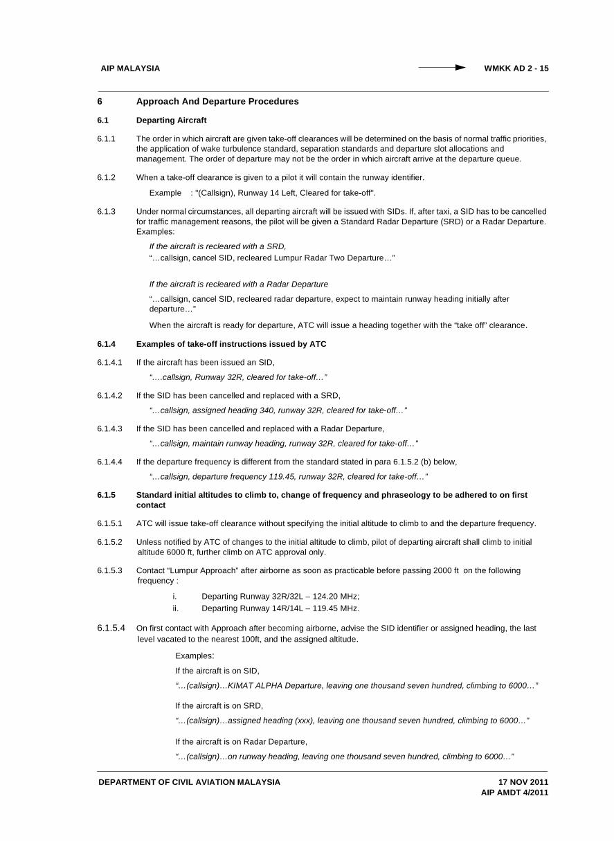
6 Approach And Departure Procedures
6.1 Departing Aircraft
6.1.1 The order in which aircraft are given take-off clearances will be determined on the basis of normal traffic priorities, the application of wake turbulence standard, separation standards and departure slot allocations and management. The order of departure may not be the order in which aircraft arrive at the departure queue.
6.1.2 When a take-off clearance is given to a pilot it will contain the runway identifier.
Example : "(Callsign), Runway 14 Left, Cleared for take-off".
6.1.3 Under normal circumstances, all departing aircraft will be issued with SIDs. If, after taxi, a SID has to be cancelled for traffic management reasons, the pilot will be given a Standard Radar Departure (SRD) or a Radar Departure. Examples:
If the aircraft is recleared with a SRD,“…callsign, cancel SID, recleared Lumpur Radar Two Departure…”
If the aircraft is recleared with a Radar Departure
“…callsign, cancel SID, recleared radar departure, expect to maintain runway heading initially after departure…”
When the aircraft is ready for departure, ATC will issue a heading together with the “take off” clearance.
6.1.4 Examples of take-off instructions issued by ATC
6.1.4.1 If the aircraft has been issued an SID,
“….callsign, Runway 32R, cleared for take-off…”
6.1.4.2 If the SID has been cancelled and replaced with a SRD,
“…callsign, assigned heading 340, runway 32R, cleared for take-off…”
6.1.4.3 If the SID has been cancelled and replaced with a Radar Departure,
“…callsign, maintain runway heading, runway 32R, cleared for take-off…”
6.1.4.4 If the departure frequency is different from the standard stated in para 6.1.5.2 (b) below,
“…callsign, departure frequency 119.45, runway 32R, cleared for take-off…”
6.1.5 Standard initial altitudes to climb to, change of frequency and phraseology to be adhered to on first contact
6.1.5.1 ATC will issue take-off clearance without specifying the initial altitude to climb to and the departure frequency.
6.1.5.2 Unless notified by ATC of changes to the initial altitude to climb, pilot of departing aircraft shall climb to initial altitude 6000 ft, further climb on ATC approval only.
6.1.5.3 Contact “Lumpur Approach” after airborne as soon as practicable before passing 2000 ft on the following frequency :
i. Departing Runway 32R/32L – 124.20 MHz;ii. Departing Runway 14R/14L – 119.45 MHz.
6.1.5.4 On first contact with Approach after becoming airborne, advise the SID identifier or assigned heading, the last level vacated to the nearest 100ft, and the assigned altitude.
Examples:If the aircraft is on SID,
“…(callsign)…KIMAT ALPHA Departure, leaving one thousand seven hundred, climbing to 6000…”
If the aircraft is on SRD,
“…(callsign)…assigned heading (xxx), leaving one thousand seven hundred, climbing to 6000…”
If the aircraft is on Radar Departure,
“…(callsign)…on runway heading, leaving one thousand seven hundred, climbing to 6000…”
17 NOV 2011AIP AMDT 4/2011

AIP MALAYSIA
DEPARTMENT OF CIVIL AVIATION MALAYSIA
WMKK AD 2 - 16
6.1.6 Immediate Take-off Clearance
A pilot receiving the ATC instruction “cleared for immediate take-off” is required to act as follows:
a) If waiting clear of the runway, taxi immediately on to it and begin take-off run without stopping the aircraft;
b) if already lined up on the runway, take-off without delay;c) if unable to comply with the instruction, inform ATC immediately.
6.1.7 Wake turbulence waiver
6.1.7.1 Pilots-in-command of departing aircraft may choose to commence take-off without the applicable wake turbulence standard being applied. In this event the following conditions will apply:
a) the pilot shall expressly initiate the request for waiver using the phraseology
“(callsign of aircraft), request wake turbulence waiver”;
b) waiver on the wake turbulence standard shall apply in VMC by day;
c) the waiver shall not apply to a LIGHT or MEDIUM aircraft taking off behind a HEAVY aircraft take-off, if the take-off by the LIGHT or MEDIUM aircraft is commenced from a point more than 150 metres along the runway in the direction of take-off, from the commencement point of the HEAVY aircraft take-off.
6.1.7.2 When a pilot-in-command requests for a wake turbulence waiver, the pilot acknowledges that ATC will no longer be responsible for the application of wake turbulence separation standards to that specific flight operation.
6.2 Landing Aircraft
6.2.1 A succeeding aircraft may be cleared to land before the preceding landing aircraft which has landed or before the preceding departing aircraft which has commenced take-off run, is clear of the runway-in-use provided the following conditions are met:
a) In VMC, by day;b) ATC must have reasonable assurance that the appropriate separation will exist when the succeeding
aircraft crosses the runway threshold;c) when issuing a landing clearance following the application of the above procedures, ATC will issue
the following aircraft with the instruction below:“... (call sign) .... preceding (aircraft type)[ vacating runway via (taxiway designator/airborne],
Runway ... (Designator) cleared to land…”
6.2.2 When the cloud base is broken or overcast, at or below 600 feet and/or the visibility is less than 2000 metres, airtraffic control will broadcast these conditions on the ATIS with an ILS approach expectation. When theseconditions exist, air traffic control will ensure that preceding (landing or departing aircraft) and vehicles do notinfringe the Localiser Sensitive Area (LSA) ahead of an arriving aircraft from the time the aircraft is 1 NM fromtouchdown until it has completed its landing run.
Note: The LSA is defined as a rectangular area contained within parallel lines 90m each side of the runway centreline and between the localizer aerial and the beginning of the runway in use.
6.3 To reduce traffic conflicts between WMKK arrivals and departures flight planned via W533 G582 VPK or G584 and vice versa, these flights may be rerouted. Expect the following SIDs or STARs from ATC.
SID/STAR RWY 32 In use RWY 14 In use
SID KIMAT Departure ISTAN DepartureW533 G582 VPK Y336 PADLI
STAR ISTAN Transition PIBOS TransitionNIPAR Arrival KIDOT Arrival
6.4 Missed Approach Procedures
6.4.1 When a pilot-in-command executes a "go round", he shall comply with the published missed approach procedurefor the runway unless given a specific alternate missed approach procedure by air traffic control. If the aircraftperformance or weather conditions preclude the pilot-in-command from complying with this requirement he shalladvise air traffic control immediately.
17 NOV 2011AIP AMDT 4/2011
AIP MALAYSIA
DEPARTMENT OF CIVIL AVIATION MALAYSIA
WMKK AD 2 - 17
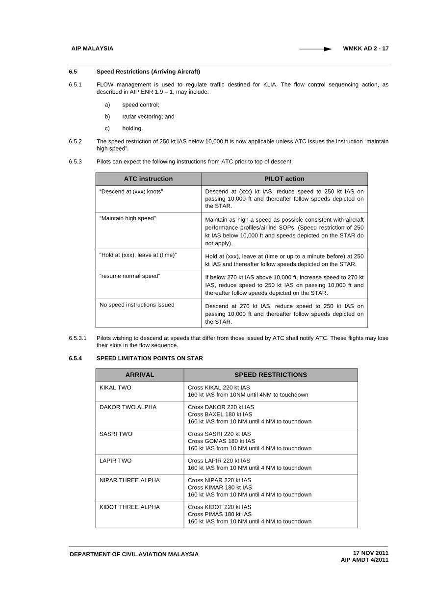
6.5 Speed Restrictions (Arriving Aircraft)
6.5.1 FLOW management is used to regulate traffic destined for KLIA. The flow control sequencing action, asdescribed in AIP ENR 1.9 – 1, may include:
a) speed control;
b) radar vectoring; and
c) holding.
6.5.2 The speed restriction of 250 kt IAS below 10,000 ft is now applicable unless ATC issues the instruction “maintainhigh speed”.
6.5.3 Pilots can expect the following instructions from ATC prior to top of descent.
6.5.3.1 Pilots wishing to descend at speeds that differ from those issued by ATC shall notify ATC. These flights may losetheir slots in the flow sequence.
6.5.4 SPEED LIMITATION POINTS ON STAR
ATC instruction PILOT action
“Descend at (xxx) knots” Descend at (xxx) kt IAS, reduce speed to 250 kt IAS onpassing 10,000 ft and thereafter follow speeds depicted onthe STAR.
“Maintain high speed” Maintain as high a speed as possible consistent with aircraftperformance profiles/airline SOPs. (Speed restriction of 250kt IAS below 10,000 ft and speeds depicted on the STAR donot apply).
“Hold at (xxx), leave at (time)” Hold at (xxx), leave at (time or up to a minute before) at 250kt IAS and thereafter follow speeds depicted on the STAR.
“resume normal speed” If below 270 kt IAS above 10,000 ft, increase speed to 270 ktIAS, reduce speed to 250 kt IAS on passing 10,000 ft andthereafter follow speeds depicted on the STAR.
No speed instructions issued Descend at 270 kt IAS, reduce speed to 250 kt IAS onpassing 10,000 ft and thereafter follow speeds depicted onthe STAR.
ARRIVAL SPEED RESTRICTIONS
KIKAL TWO Cross KIKAL 220 kt IAS160 kt IAS from 10NM until 4NM to touchdown
DAKOR TWO ALPHA Cross DAKOR 220 kt IAS Cross BAXEL 180 kt IAS 160 kt IAS from 10 NM until 4 NM to touchdown
SASRI TWO Cross SASRI 220 kt IASCross GOMAS 180 kt IAS 160 kt IAS from 10 NM until 4 NM to touchdown
LAPIR TWO Cross LAPIR 220 kt IAS160 kt IAS from 10 NM until 4 NM to touchdown
NIPAR THREE ALPHA Cross NIPAR 220 kt IASCross KIMAR 180 kt IAS160 kt IAS from 10 NM until 4 NM to touchdown
KIDOT THREE ALPHA Cross KIDOT 220 kt IASCross PIMAS 180 kt IAS160 kt IAS from 10 NM until 4 NM to touchdown
17 NOV 2011AIP AMDT 4/2011
AIP MALAYSIA
DEPARTMENT OF CIVIL AVIATION MALAYSIA
WMKK AD 2 - 18
6.5.5 SPEED LIMITATION POINTS WHEN STAR IS CANCELLED
6.5.5.1 Pilots shall adopt the following speeds when notified that the STAR is cancelled:
a) Under radar vectors• 250 kt IAS on passing 10,000ft;• 220 kt IAS on turning base;• 180 kt IAS on turning to intercept the localizer;• 160 kt IAS from 10 NM until 4 NM to touchdown.
b) Own navigation to intercept the final approach track• 250 kt IAS on passing 10,000ft;• 220 kt IAS 20 track miles from touchdown;• 180 kt IAS 15 track miles from touchdown;• 160 kt IAS from 10 NM until 4 NM to touchdown.
6.5.5.2 ATC may issue other speeds to achieve a more accurate spacing, e.g. 220 kt IAS prior to base turn.
6.5.6 CANCELLATION OF SPEED RESTRICTIONS
6.5.6.1 Pilots need not adopt the speed restrictions at the speed limitation points when they are issued a “No ATC SpeedRestriction” clearance by ATC.
7 Hazardous Weather Warning
7.1 Pilots will be advised when there are reported occurences of micro burst or windshear. These alerts will be in thefollowing form:
a) Runway designation;b) Arrival or Departure;c) Type of alert (micro burst or wind shear);d) Quantified headwind loss or gain;e) Location of alert, in nauticle mile, on final approach or departure path;
Example " ........C/S, Runway 14L, arrival, micro burst, headwind loss 40 knots, 2 mile final".
8 Low Visibility Operating Procedures
8.1 General
8.1.1 There are 3 visibility conditions under which the airport may be required to operate :
a) Condition 1. Visibility is sufficient for pilots to taxi aircraft and to avoid collision with other traffic ontaxiways and at intersections by visual reference, and for air traffic control to exercise control over allmanoeuvring area traffic on the basis of visual reference. This condition shall apply when the visibility isgreater than 2000 metres.
b) Condition 2. Visibility is sufficient for pilots to taxi aircraft and to avoid collision with other traffic ontaxiways and at intersection by visual reference, but insufficient for air traffic control to exercise controlover all manoeuvring area traffic on the basis of visual reference. This condition shall apply when thevisibility is 2000 metres but greater than 600 metres.
c) Condition 3. Visibility is 600 metres or less.
8.2 Visibility Condition 2
8.2.1 When visibility condition is 2000 metres or less but greater than 600 metres, Condition 2 low visibility operatingprocedures will be applied by air traffic control.
8.2.2 Responsibility for separation and regulation of aircraft and vehicles shall be as follows :
a) Air traffic control shall be responsible for the regulation of aircraft and vehicles with respect to other aircraftand the provision of essential traffic information on aircraft to pilots-in-command and drivers of vehicles tofacilitate separation;
b) Pilots-in-command shall be responsible for maintaining separation with other aircraft on the manoeuvringarea, other than the runways;
c) Drivers of vehicles shall be responsible for separation with aircraft and other vehicles.
17 NOV 2011AIP AMDT 4/2011
AIP MALAYSIA
DEPARTMENT OF CIVIL AVIATION MALAYSIA
WMKK AD 2 - 19
8.2.3 When low visibility operating procedures are in operation air traffic control will :
a) Broadcast on the ATIS that low visibility operating procedures are in operation.b) Ensure that, during the currency of low visibility operating procedures no vehicle or aircraft is permitted to
infringe the Localiser Sensitive Area (LSA) ahead of an ariving aircraft from the time the aircraft is 1NMfrom touchdown until it has completed its landing run. Landing clearance will not be issued if the LSA isknown to be infringed.
c) Provide runway landing intervals of 6NM or more.d) Provide landing clearances no later than 2NM from touchdown.e) Provide pilot-in-command of every landing aircraft with :
i. The current RVR reading for the landing runway;ii. Un-serviceability of any component parts of the CAT II facilities not previously broadcast on the
ATIS
8.2.4 When low visibility operating procedures are in operation pilots-in-command shall :a) Ensure that after landing, the aircraft clears the LSA as soon as possible after landing.b) Be aware that any emergency conditions (brake fire etc) may not be visible to the control tower, apron
control tower or AFRS.
8.3 Visibility Condition 3
8.3.1 When visibility conditions reduce to 600 metres or less, Condition 3 low visibility operating procedures shall be applied in addition to those defined for Condition 2.
8.3.2 Responsibility for separation and regulation of aircraft and vehicles shall be as follows :
a) Air traffic control will separate aircraft from aircraft, and vehicles from aircraft using the following methods:
i. Pilots-in-command will be provided with taxiing clearances and clearance limits which, in theevent of a potential conflict, require the pilot-in-command to hold short of a taxiway intersectionand report sighting and able to follow, or pass behind, the conflicting aircraft.
ii. If the pilot-in-command is not able to sight the conflicting aircraft, further clearance to proceedwill be withheld until the preceding aircraft has passed, and reported passing, the next taxiwayintersection.
iii. If the pilot-in-command, after reporting the conflicting traffic sighted, reports that visual contacthas been lost, he shall be instructed to hold position and the separation procedure as in (ii)above re-established.
b) Pilots-in-command, who have reported sighting and able to follow or pass behind another aircraft orvehicle, shall be responsible for maintaining separation with that aircraft or vehicle. If visual contact is lost,the pilots-in-command shall inform air traffic control immediately.
8.3.3 When low visibility operating procedures are in operation air traffic control will :
a) Direct all departing aircraft to use the full length of the runway.b) Apply positive control techniques for separation between aircraft on the manoeuvring area.c) Pass essential traffic information in respect of aircraft to other aircraft that may be in conflict.d) Pass to aircraft approaching the holding point, essential traffic information in respect of aircraft already
holding.
8.3.4 When low visibility operating procedures are in operation pilots-in-command shall adjust aircraft taxiing speeds to ensure that they are able to comply with ATC instructions.
9 Runway Operations
9.1 Modes Of Operation
9.1.1 Under normal traffic conditions, segregated operations ( one runway for departures, and the other runway forarrivals) will be used at KL International Airport. Normal operating runway mode selections will be :
a) Runway 32 Right for departures and Runway 32 Left for arrivalsb) Runway 14 Right for departures and Runway 14 Left for arrivals
9.1.2 Under heavier traffic conditions, a semi-mixed mode of opeartion (2 Arrivals/1 Departure) or (2 Departures/1Arrival) may be implemented depending on the disposition of traffic i.e. the former will be implemented if thearrivals substantially outnumber the departures or the latter will be implemented if the departures outnumber thearrivals.
17 NOV 2011AIP AMDT 4/2011

AIP MALAYSIA
DEPARTMENT OF CIVIL AVIATION MALAYSIA
WMKK AD 2 - 20
9.1.3 If the arrivals and departures are equally heavy, then a mixed mode of operation will be implemented with bothrunways used for arrivals as well as departures..
9.2 Independent Parallel Approaches
9.2.1 When simultaneous parallel approaches are being conducted at KL International Airport, pilots will be advisedeither directly or through the ATIS.
9.2.2 Simultaneous parallel approaches will require all aircraft to conduct ILS approaches. When pilots are conductingsimultaneous parallel approaches at KL International Airport, aircraft tracks will be monitored by radar and, in theevent that an aircraft diverges from centre line towards the adjacent approach path, either a transgressionwarning or alert will be generated depending on the extend of the path divergence. If the divergence fromcentreline by the aircraft is a minor adjustment only, then a warning will be received by air traffic control. Underthese circumstances air traffic control will instruct the pilot-in-command
"Call sign, Turn Left/right and return to the localiser centre line, advise intentions".
9.2.3 If the pilot-in-command is able to return the aircraft to the centreline, he shall immediately advise air traffic controlof this fact. If, due to the nature of the cause for divergence, the pilot-in-command has a problem and cannotreturn the aircraft to the centre line he shall immediately advise air traffic control of the problem and his intentions.
9.2.4 If the divergence from centreline is cross then an alert will be received by air traffic control. Under thesecircumstances air traffic control may instruct the pilots-in-command of the aircraft which are NOT DIVERGING toexecute a go round and will turn those aircraft outwards, with respect to the two runways. ( ie away from thediverging aircraft ).
9.2.5 The pilot-in-command of an aircraft that is forced to make a major divergence from centreline shall advise airtraffic control as soon as possible of the problem and intentions.
9.3 Change Of Runway Whilst On Final ( Side Step )
9.3.1 Air traffic control may offer pilots-in-command a change of runway in order to resolve a problem, such as apotential missed approach. A change of runway, or side step, to the adjacent runway will not be made availableonce the aircraft is closer than 8NM from touchdown for the new runway. In any event, the change of runway willonly be available under the following conditions:
a) Pilot-in-command has visual contact with the terrain has the adjacent runway in sight and in-flight visibilityis greater than 5000m.
b) Pilot-in-command agrees to, or has requested, the change.c) The new localiser frequency is advised to the pilot.
9.3.2 The procedure is used by day only.Example of the phraseology that may be used is as follows:
(ATC) "..........C/S, side step to Runway 32 right available, can you comply with the 32R procedure".
(Pilot) "...........C/S, affirm/negative".
(ATC) "...........C/S, make side step procedure to runway 32 right,
new localiser frequency.......Mhz, report re-established on final".
(Pilot) "...........Established on final".
(ATC) "...........C/S, Contact Lumpur Tower, frequency .........Mhz.
1 Bird Concentrations In The Vicinity Of The Airport
1.1 Studies show that the airport is within the flight path of seasonal migratory birds. The birds migrate from the north-east between September and November and from the south east between February and April. Height is between100 metres to 900 metres. The most common bird types are Black Baza, Crested Honey Buzzard, Grey-facedBuzzard and Chinese Goshawk.
2 Touch And Go Landings
2.1 Touch and go landings are not permitted.
WMKK AD 2.23 ADDITIONAL INFORMATION
17 NOV 2011AIP AMDT 4/2011
DEPARTMENT OF CIVIL AVIATION MALAYSIA
AIP MALAYSIA WMKK AD 2 - 20.1
3 Aircraft night stop at Taxiway Lima (L).
3.1 Certain portions of Taxiway L at the existing Low Cost Carrier Terminal will be used for parking aircraft from1600UTC to 2300UTC.
3.2 The numbering for the night parking stands are: F79, F80, F89, F90, F99, F100, F109 and F110. The baycoordinates as follows: (refer to WMKK AD 2- 25B)
F79 - 0244.554N 10143.301E
F80 - 0244.514N 10143.326E
F89 - 0244.484N 10143.346E
F90 - 0244.441N 10143.375E
F99 - 0244.410N 10143.395E
F100 - 0244.369N 10143.423E
F109 - 0244.337N 10143.344E
F110 - 0244.294N 10143.437E
3.3 All aircraft parked on taxiway Lima shall face North.
3.4 There will be minimum markings on Taxiway Lima - only an aircraft stop loop to indicate the aircraft parkingposition.
4 Arrival procedures
4.1 When Taxiway Lima is closed, the taxiway becomes a night stop parking apron. The safety, security andcleanliness of the area is the responsibility of AirAsia.
4.2 Three red hazard lights will be positioned at begining of Taxiway Lima (minimum distance of 57.5M from TaxiwayKilo) to mark the closure of the taxiway. Taxiway Lima will be closed from 1600UTC to 2300UTC. During theclosure time, all aircraft shall use Taxiway Bravo for arrivals and departures.
4.3 When Taxiway Lima is closed to be a night stop parking apron, the taxiway centerline lights will be switch off. Theelevated taxiways edge lights at Taxiway Lima are removed to provide space for ground vehicle movements.
4.4 All arriving aircraft shall report to ATC upon marshaller in sight. On confirmation that pilot has marshaller in sight,pilot shall follow marshaller’s instruction to parking bay.
4.5 After all the aircraft has parked at the LCCT Taxiway Lima, the extension Taxiway Bravo to LCCT is closed. Threered hazard lights shall be placed at begining of extension taxiway Bravo to denote its closure.
5 Departure Procedures
5.1 Fifteen minutes prior to the first departure, the centerlines lights for Taxiway Lima, Taxiway Bravo and intersection’N1 and N2’ shall be switch on. The three red hazard lights at Taxiway Lima and Taxiway Bravo will be switch off.
5.2 The safe distance for jet blast clearance is 100 meters or the space/distance of 2 parked aircraft. Aircraft shall towforward to attain the required jet blast clearance before starting up.
5.3 After the last aircraft has taxied off the night parking stand on Taxiway Lima for departure, the Taxiway Lima willbe open for operations.
17 NOV 2011AIP AMDT 4/2011

THIS PAGE INTENTIONALLY LEFT BLANK