WM 600PE Product Ejection System -...
49
WM 600PE Product Ejection System Customer Product Manual Part 331 179B02 NORDSON CORPORATION D Duluth, Georgia www.nordson.com
Transcript of WM 600PE Product Ejection System -...

WM 600PE ProductEjection System
Customer Product ManualPart 331 179B02
NORDSON CORPORATION � Duluth, Georgiawww.nordson.com
� 2002 Nordson CorporationAll rights reserved
331179B02
Issued 3/0265-WM600-MA-03
Nordson Corporation welcomes requests for information, comments and inquiries about its products. Generalinformation about Nordson can be found on the Internet using the following address: http://www.nordson.com.
Address all correspondence to:
Nordson CorporationAttn: Customer Service11475 Lakefield Drive
Duluth, GA 30097
Notice
This is a Nordson Corporation publication which is protected by copyright. Original copyright date 1999. No part ofthis document may be photocopied, reproduced, or translated to another language without the prior written consent
of Nordson Corporation. The information contained in this publication is subject to change without notice.
Trademarks
AquaGuard, Blue Box, Control Coat, Equi=Bead, FoamMelt, FoamMix, Helix, Hot Shot, Hot Stitch, Meltex,MicroSet, MultiScan, Nordson, the Nordson logo, OmniScan, Package of Values, Porous Coat, Posi-Stop, ProLink,
PRX, RBX, Shur-Lock, UniScan, UpTime, and Versa-Spray are registered trademarks of Nordson Corporation.
BetterBook, CF, Controlled Fiberization, Eclipse, Saturn, Seal Sentry, Swirl Coat, and Vista are trademarks of Nordson Corporation.
Table of Contents i
� 2002 Nordson CorporationAll rights reserved
331179B02
Issued 3/02 65-WM600-MA-03
Table of Contents
1. Safety 1. . . . . . . . . . . . . . . . . . . . . . . . . . . . . . . . . . . . . . . . . . . . . . . . . . . . .
Safe Operation 1. . . . . . . . . . . . . . . . . . . . . . . . . . . . . . . . . . . . . . . . . . .
Safety Symbols 2. . . . . . . . . . . . . . . . . . . . . . . . . . . . . . . . . . . . . . . . . . .
Qualified Personnel 3. . . . . . . . . . . . . . . . . . . . . . . . . . . . . . . . . . . . . . .
Intended Use 3. . . . . . . . . . . . . . . . . . . . . . . . . . . . . . . . . . . . . . . . . . . . .
Installation and Electrical Connections 4. . . . . . . . . . . . . . . . . . . . . . .
Operation 5. . . . . . . . . . . . . . . . . . . . . . . . . . . . . . . . . . . . . . . . . . . . . . . .
Less-Obvious Dangers 6. . . . . . . . . . . . . . . . . . . . . . . . . . . . . . . . . .
Action in the Event of System Malfunction 6. . . . . . . . . . . . . . . . .
Maintenance/Repair 7. . . . . . . . . . . . . . . . . . . . . . . . . . . . . . . . . . . . . . .
Cleaning 8. . . . . . . . . . . . . . . . . . . . . . . . . . . . . . . . . . . . . . . . . . . . . . . . .
Liquid Adhesives 9. . . . . . . . . . . . . . . . . . . . . . . . . . . . . . . . . . . . . . . . . .
2. Description 10. . . . . . . . . . . . . . . . . . . . . . . . . . . . . . . . . . . . . . . . . . . . . . . .
Functional Description 10. . . . . . . . . . . . . . . . . . . . . . . . . . . . . . . . . . . .
Specifications 11. . . . . . . . . . . . . . . . . . . . . . . . . . . . . . . . . . . . . . . . . . .
Dimensions 11. . . . . . . . . . . . . . . . . . . . . . . . . . . . . . . . . . . . . . . . . . . . .
3. Installation 12. . . . . . . . . . . . . . . . . . . . . . . . . . . . . . . . . . . . . . . . . . . . . . . .
Unpacking 12. . . . . . . . . . . . . . . . . . . . . . . . . . . . . . . . . . . . . . . . . . . . . .
Mounting the Product Ejector 12. . . . . . . . . . . . . . . . . . . . . . . . . . . . . .
Making the Electrical Connections 16. . . . . . . . . . . . . . . . . . . . . . . . .
Making the Solenoid Valve Connections 17. . . . . . . . . . . . . . . . . . . .
Setting the WM 500 Unit 17. . . . . . . . . . . . . . . . . . . . . . . . . . . . . . . . . .
Alarm-Point Setting 17. . . . . . . . . . . . . . . . . . . . . . . . . . . . . . . . . . . .
Marking-Length Setting 18. . . . . . . . . . . . . . . . . . . . . . . . . . . . . . . . .
Making the Final Adjustments 18. . . . . . . . . . . . . . . . . . . . . . . . . . . . .

Table of Contentsii
� 2002 Nordson CorporationAll rights reserved
331179B02
Issued 3/0265-WM600-MA-03
4. Optional Product Ejector Configurations 20. . . . . . . . . . . . . . . . . . . . . . .
Changing the Ejector Configuration 20. . . . . . . . . . . . . . . . . . . . . . . .
Disassemble the Ejector 20. . . . . . . . . . . . . . . . . . . . . . . . . . . . . . . .
Assemble the Ejector for Left-Hand Use 21. . . . . . . . . . . . . . . . . .
Reverse the Motor 22. . . . . . . . . . . . . . . . . . . . . . . . . . . . . . . . . . . . .
Changing the Motor Location 23. . . . . . . . . . . . . . . . . . . . . . . . . . . . . .
Disassemble the Motor 23. . . . . . . . . . . . . . . . . . . . . . . . . . . . . . . . .
Assemble the Motor on the Left Side 25. . . . . . . . . . . . . . . . . . . . .
5. Operation 26. . . . . . . . . . . . . . . . . . . . . . . . . . . . . . . . . . . . . . . . . . . . . . . . .
6. Troubleshooting 27. . . . . . . . . . . . . . . . . . . . . . . . . . . . . . . . . . . . . . . . . . . .
7. Repair 29. . . . . . . . . . . . . . . . . . . . . . . . . . . . . . . . . . . . . . . . . . . . . . . . . . . .
Replacing the Disk 29. . . . . . . . . . . . . . . . . . . . . . . . . . . . . . . . . . . . . . .
Replacing a Wheel or Wheel Tread 30. . . . . . . . . . . . . . . . . . . . . . . . .
8. Parts 31. . . . . . . . . . . . . . . . . . . . . . . . . . . . . . . . . . . . . . . . . . . . . . . . . . . . .
Using the Illustrated Parts List 31. . . . . . . . . . . . . . . . . . . . . . . . . . . . .
Product Ejection System Parts 32. . . . . . . . . . . . . . . . . . . . . . . . . . . . .
Wheel Assembly Parts 37. . . . . . . . . . . . . . . . . . . . . . . . . . . . . . . . . . . .
Motor Control Box Parts 38. . . . . . . . . . . . . . . . . . . . . . . . . . . . . . . . . .
Recommended Spare Parts 42. . . . . . . . . . . . . . . . . . . . . . . . . . . . . . .
9. Wiring Diagrams 43. . . . . . . . . . . . . . . . . . . . . . . . . . . . . . . . . . . . . . . . . . .
WM 600PE Product Ejection System 1
� 2002 Nordson CorporationAll rights reserved
331179B02
Issued 3/02 65-WM600-MA-03
WM 600PE Product Ejection System
WARNING: Allow only qualified personnel to perform thefollowing tasks. Follow the safety instructions in this documentand all other related documentation.
Safety instructions contained in this section and throughout thisdocument apply to tasks that may be performed with the liquid adhesiveapplication system components and the liquid adhesive used. It is veryimportant that these safety instructions are always followed. Failure to doso could result in personal injury, death and/or damage to the system orother equipment.
With this in mind, here are some basic safety recommendations:
� Read and become familiar with the Safety section prior to installing,operating, maintaining, or repairing the system.
� Read and follow the warnings which appear within the text and arerelated to specific tasks.
� Store this document within easy reach of personnel operating ormaintaining the system.
� Wear personal protective equipment such as safety goggles, gloves,or respiratory equipment where this is required by peculiarities of thesystem and/or the material.
� Familiarize yourself with and follow all safety instructions prescribedby your company, general accident prevention regulations, andgovernment safety regulations.
1. Safety
Safe Operation
WM 600PE Product Ejection System2
� 2002 Nordson CorporationAll rights reserved
331179B02
Issued 3/0265-WM600-MA-03
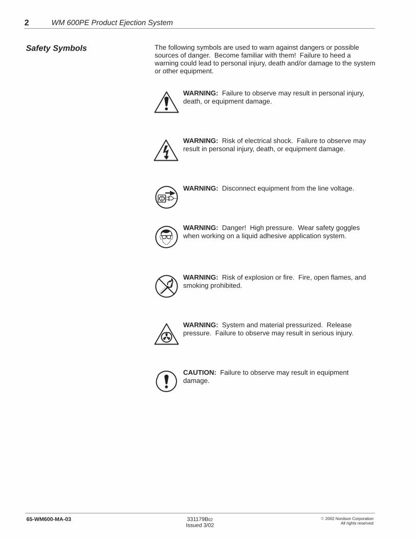
The following symbols are used to warn against dangers or possiblesources of danger. Become familiar with them! Failure to heed awarning could lead to personal injury, death and/or damage to the systemor other equipment.
WARNING: Failure to observe may result in personal injury,death, or equipment damage.
WARNING: Risk of electrical shock. Failure to observe mayresult in personal injury, death, or equipment damage.
WARNING: Disconnect equipment from the line voltage.
WARNING: Danger! High pressure. Wear safety goggleswhen working on a liquid adhesive application system.
WARNING: Risk of explosion or fire. Fire, open flames, andsmoking prohibited.
WARNING: System and material pressurized. Releasepressure. Failure to observe may result in serious injury.
CAUTION: Failure to observe may result in equipmentdamage.
Safety Symbols

WM 600PE Product Ejection System 3
� 2002 Nordson CorporationAll rights reserved
331179B02
Issued 3/02 65-WM600-MA-03
”Qualified personnel” is defined here as individuals who thoroughlyunderstand the equipment and its safe operation, maintenance, andrepair. Qualified personnel are physically capable of performing therequired tasks, familiar with all relevant safety rules and regulations, andhave been trained to safely install, operate, maintain, and/or repair theequipment. It is the responsibility of the company operating theequipment to see that its personnel meet these requirements.
The system is designed and intended to be used only for the purposedescribed in the Description section. Uses not in accordance with thatsection or as described in this document are considered unintended usesand not in accordance with governing regulations.
WARNING: Use of this equipment in ways other thandescribed in this document may result in personal injury, death,or equipment damage.
The following actions of the owner or operator of the system are some,but not all, examples of unintended use which would permit Nordson toclaim it is not responsible for personal injury or property damage arisingfrom such unintended use:
� Unapproved modifications or changes to the system
� Failure to comply with the safety instructions
� Failure to comply with the instructions concerning installation, use,operation, maintenance, or repair, or when these tasks are carried outby unqualified personnel
� Use of inappropriate or incompatible foreign materials or auxiliaryequipment
� Failure to observe workplace safety rules or regulations issued bygovernment authorities or safety councils.
Qualified Personnel
Intended Use

WM 600PE Product Ejection System4
� 2002 Nordson CorporationAll rights reserved
331179B02
Issued 3/0265-WM600-MA-03
� Prior to installation, check intended location and surrounding area forany potential hazards during operation.
� All electrical, pneumatic, gas and hydraulic connections, andinstallation of all system components may only be carried out byqualified personnel. Observe installation instructions for componentsand accessories.
� Equipment must be properly grounded and fused according to therated current consumption (see ID plate).
� Cables which run outside the system must regularly be checked forwear or damage.
� Power supply wire gauge and insulation must be sufficient to handlerated current consumption.
� Cables must never be squeezed or pinched. Do not locate cables orhoses in high traffic areas.
� Check liquid adhesive feed hoses, screwed connections, andcompressed air lines regularly for leaks. These are to be replaced atthe first signs of cracks, brittleness etc. Release system pressurecompletely beforehand.
WARNING: Failure to install the system properly, andespecially failure to ensure electrical, pressurized, and highpressure feed connections are made correctly, may result inserious injury or death.
Installation and ElectricalConnections
WM 600PE Product Ejection System 5
� 2002 Nordson CorporationAll rights reserved
331179B02
Issued 3/02 65-WM600-MA-03
The system should only be operated when it is in working order. It shouldonly by operated by qualified persons following all regulations valid forliquid adhesive systems.
� Never allow the system to be operated by personnel under theinfluence of substances which reduce their reaction times, or who arenot able to operate the equipment for physical reasons.
� Prior to each startup of the system, check protection and warningdevices and make sure they are fully functional. Do not operate theequipment if these devices are not functioning properly.
� When the removal of safety equipment is required for installation,maintenance, or repair, it must be reconnected immediately uponcompletion of the work.
� In a humid environment, only equipment featuring a correspondingclass of protection may be operated.
� Do not operate the system in an explosive environment.
� Keep parts of the body and clothing away from rotating parts. Do notwear loose articles of clothing when operating or servicing equipmentwith rotating parts. Remove wrist watches, rings, necklaces or similarjewelry and pin up or cover long hair before performing any work onor with the equipment. The wearing of protective gloves may provehazardous in certain circumstances where rotating parts are presentand may therefore be forbidden.
� To carry out measurements on the substrate or system components,switch off parent machine and/or system and wait until the equipmentcomes to a standstill.
� Never point guns or applicator nozzles at yourself or other persons.
Operation
WM 600PE Product Ejection System6
� 2002 Nordson CorporationAll rights reserved
331179B02
Issued 3/0265-WM600-MA-03
Less-Obvious Dangers
WARNING: An operator or service technician working with theequipment should be aware of the less-obvious dangers thatoften cannot be completely minimized at production sites:
� Pressurized system components
� The possibility that electrical potentials may remain in the systemafter the system was de-energized
� Liquid adhesive vapors
� Hydraulically or pneumatically operated system components
� Uncovered winding parts
Action in the Event of System Malfunction
If the system malfunctions, switch it off immediately.
� Turn the main switch off, or use emergency stop switch or similarsafety feature as provided.
� After equipment has come to a standstill and before reoperating it,have it repaired by qualified personnel.
WM 600PE Product Ejection System 7
� 2002 Nordson CorporationAll rights reserved
331179B02
Issued 3/02 65-WM600-MA-03
Allow only qualified personnel to perform the procedures described in thisdocument. Work should only be carried out on a completelydepressurized system, following all safety procedures.
NOTE: Depending on the configuration of the liquid adhesive applicationsystem, high pressure may remain between application head(s) andpressure regulator or pump/s even after the system has been switchedoff using the main switch or the emergency stop. This especially appliesto multi-hose configurations between pump/s and application head/s.
� Prior to maintenance and repair work it is therefore essential toensure that all liquid adhesive application system components aredepressurized as follows:
1. Release input pressure in front of pump by shutting off customercompressed air supply.
2. Release any remaining system pressure behind the pumps bymanually operating the application heads.
� Secure pneumatically-and hydraulically-operated equipment againstuncontrolled movement.
� Switch off system electrically.
WARNING: Some voltage is still present in the control cabineteven after equipment has been turned off at the main switch.Complete the following steps prior to maintenance or repair:
1. Disconnect external power supply.
2. Lock out external power supply.
3. Check no voltage is present.
4. Ground and short.
5. Cover nearby live sections.
If liquid adhesive application system is left idle for extended periods (e.g.overnight or long breaks) Nordson recommends applying Vaseline to theapplication head nozzles to prevent them from drying out and becomingblocked as a result.
� Only use genuine Nordson parts.
Maintenance/Repair

WM 600PE Product Ejection System8
� 2002 Nordson CorporationAll rights reserved
331179B02
Issued 3/0265-WM600-MA-03
NOTE: Always refer to the liquid adhesive manufacturer’s MaterialSafety Data Sheet or material information sheet before working with anycleaning fluids.
WARNING: Never clean any aluminium part or flush anysystem using halogenated hydrocarbon fluids. Examples ofcommon halogenated hydrocarbons are: dichloromethylene,1,1,1-trichloroethylene, and perchlorethylene. Halogenatedhydrocarbons may react violently with aluminium parts.
� Never use an open flame to clean the system or its components.
� Check that (warm) water can be used to clean the liquid adhesivesystem components, possibly with the addition of householdwashing-up liquid. If this is not possible, use only the cleaning fluidstated in the liquid adhesive manufacturer’s information. If themanufacturer recommends heating the cleaner, note the flash point.
� Ensure sufficient room ventilation to draw off vapors.
WARNING: Fire, open flames and smoking are prohibitedwhen cleaning fluids are used. Observe all explosionprevention regulations. Cleaning fluids may only be heatedusing temperature controlled and explosion-protected heaters.
� Disposal must be according to the waste key in the DIN Safety DataSheet. Liquid adhesives or residue, solvent, or separating agentsmust not be released into open waterways. In the case of a leak orspillage, contain liquid and if necessary use an absorbant material(e.g., sawdust) to soak it up; then proceed according to the relevantwaste disposal regulations.
� If the liquid adhesive application system is to be idle for an extendedperiod, the entire system should be flushed and outlets sealed withVaseline. Warm water is usually used to flush application systemswith which water based liquid adhesives are processed.
� If the liquid adhesive manufacturer specially recommends a flushingagent, the manufacturer’s safety and disposal details must befollowed.
Cleaning

WM 600PE Product Ejection System 9
� 2002 Nordson CorporationAll rights reserved
331179B02
Issued 3/02 65-WM600-MA-03
As there is a wide variety of liquid adhesives available with differentcompositions and characteristics, it is impossible here to give anexhaustive list of safety notes reflecting the typical characteristics ofliquid adhesives. The use of liquid adhesives in Nordson’s liquidadhesive application systems therefore requires reference to the liquidadhesive manufacturer’s documents beforehand.
Information relating to safety aspects e.g. concerning solvent content,hazards and countermeasures in the event of liquid adhesive coming intocontact with skin or mucous membranes are contained in the technicaldata sheets and the DIN Safety Data Sheets from the manufacturer.
� Always refer to the manufacturer’s Material Safety Data Sheet ormaterial information before working with any liquid adhesives.
� It may be necessary to refer to the manufacturer’s notes on the use ofmaterials from a third party. These may be required for processing aliquid adhesive, but hazards arising from their use are not necessarilymentioned by the manufacturer of the liquid adhesive.
� Liquid adhesives may still give off vapors when they are processedcorrectly. The smell produced can cause some annoyance. This isespecially true where liquid adhesives are used that contain solvent,thus requiring the use of breathing equipment (e.g., a filter).
� If the prescribed processing conditions are not followed, harmfuldecomposition products may develop. Therefore, the vapors must beremoved.
� Wash hands well before breaks and when work is finished.
� If liquid adhesive comes into contact with eyes or mucousmembranes, rinse well with water—especially the eyes. Changedamp clothes, and seek medical advice if it is swallowed.
� Disposal must be according to the waste key in the DIN Safety DataSheet. Liquid adhesives or residue, solvent, or separating agentsmust not be released into open waterways. In the case of a leak orspillage, contain liquid and if necessary use an absorbant material(e.g., sawdust) to soak it up; then proceed according to the relevantwaste disposal regulations.
� If solvents or separating agents are used to process a liquidadhesive, follow the safety and disposal information from themanufacturer.
Liquid Adhesives

WM 600PE Product Ejection System10
� 2002 Nordson CorporationAll rights reserved
331179B02
Issued 3/0265-WM600-MA-03
The Nordson WM 600PE product ejection system is a component of aliquid adhesive (cold glue) system. After a product is glued, a detectionsystem determines whether the glue was properly applied. If the gluewas not properly applied, the detection system signals the productejection system to eject the product from the production line. By usingthe product ejection system, you can ensure that only properly gluedproducts stay on your production line. Figure 1 shows the majorcomponents of the product ejection system.
5000005A
1
7
6
5
4
3
2
Fig. 1 Product Ejection System Components
1. Motor2. Motor control box3. Mounting clamp4. Clamp wheel
5. Guide wheel6. Disk7. Solenoid valve
The product ejector is mounted on the transfer section of a folder-gluermachine, just ahead of where the products enter the compressionsection. The ejector has two wheels: a clamp wheel and a guide wheel.Normally, the clamp wheel is raised and the guide wheel rests on thedisk. When the ejector receives a signal to eject a product, the clampwheel lowers to press the product against the disk and feed it under theguide wheel. The guide wheel then ejects the product from theproduction line. The clamp wheel raises after the product is ejected.
2. Description
Functional Description
WM 600PE Product Ejection System 11
� 2002 Nordson CorporationAll rights reserved
331179B02
Issued 3/02 65-WM600-MA-03
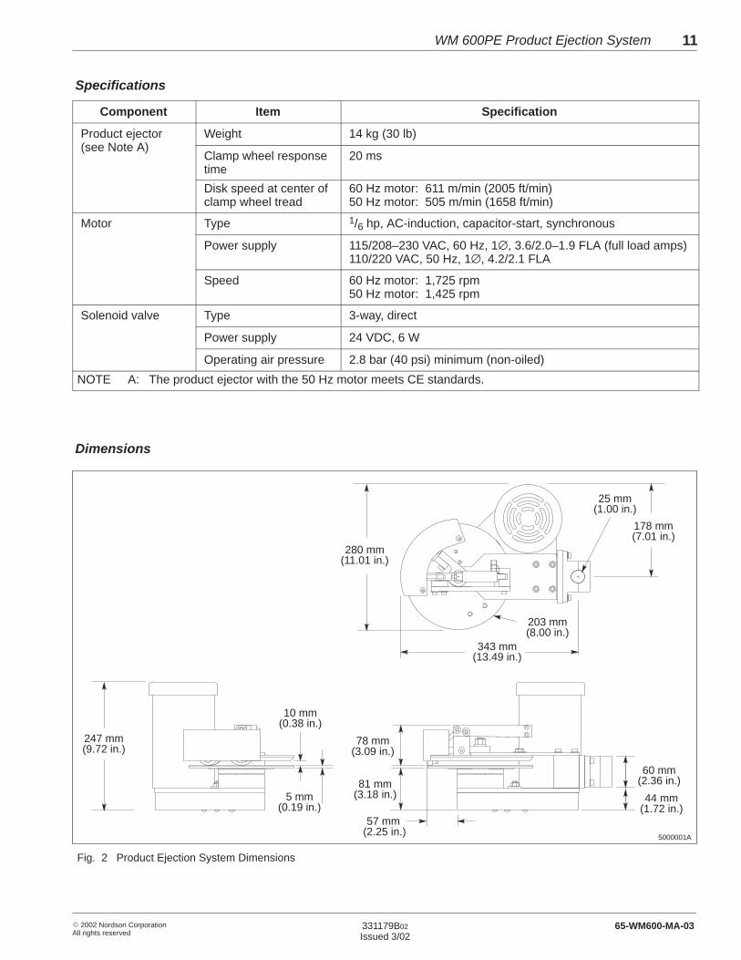
Component Item Specification
Product ejector Weight 14 kg (30 lb)(see Note A)
Clamp wheel responsetime
20 ms
Disk speed at center ofclamp wheel tread
60 Hz motor: 611 m/min (2005 ft/min)50 Hz motor: 505 m/min (1658 ft/min)
Motor Type 1/6 hp, AC-induction, capacitor-start, synchronous
Power supply 115/208–230 VAC, 60 Hz, 1∅, 3.6/2.0–1.9 FLA (full load amps)110/220 VAC, 50 Hz, 1∅, 4.2/2.1 FLA
Speed 60 Hz motor: 1,725 rpm50 Hz motor: 1,425 rpm
Solenoid valve Type 3-way, direct
Power supply 24 VDC, 6 W
Operating air pressure 2.8 bar (40 psi) minimum (non-oiled)
NOTE A: The product ejector with the 50 Hz motor meets CE standards.
5000001A
247 mm(9.72 in.)
10 mm(0.38 in.)
5 mm(0.19 in.)
280 mm(11.01 in.)
343 mm(13.49 in.)
203 mm(8.00 in.)
178 mm(7.01 in.)
25 mm(1.00 in.)
78 mm(3.09 in.)
81 mm(3.18 in.)
57 mm(2.25 in.)
60 mm(2.36 in.)
44 mm(1.72 in.)
Fig. 2 Product Ejection System Dimensions
Specifications
Dimensions
WM 600PE Product Ejection System12
� 2002 Nordson CorporationAll rights reserved
331179B02
Issued 3/0265-WM600-MA-03
Use these procedures to install the product ejection system.
The product ejection system is shipped fully assembled. Exercise normalcare to prevent equipment damage during unpacking. After unpackingthe equipment, inspect it for any damage that may have occurred duringshipping. Look for dents and scratches and make sure all fasteners aretight. Report any damage to your Nordson representative.
Follow this procedure to mount the product ejector.
1. Make sure you have the following customer-supplied items:
� customized bracketry and a 25 mm (1 in.) diameter mounting rod
� wiring to connect the solenoid valve to the detection system
� air line tubing to connect the air pressure regulator/filter to an airsupply
� wiring to connect the motor control box to a power supply
� an electrical disconnect with lock-out capability
2. Use appropriate bracketry and a 25 mm (1 in.) diameter mounting rodto mount the product ejector on the folder-gluer. Make sure thecompleted installation meets the following requirements:
� Mount the ejector on the transfer section of the folder-gluer, justahead of where the products enter the compression section. Usethe procedures in the next section, Optional Product EjectorConfigurations, as needed to adjust the mounting of the productejector to accommodate your installation.
NOTE: The product ejector can be mounted on either the right- orleft-hand side of the production line. For left-hand mounting, theejector must be partially disassembled and reconfigured, and themotor’s direction of rotation must be reversed. The motor canalso be switched from the right side to the left side. Figures 3 and4 show examples of right- and left-hand mounting configurationswith the motor on either the right- or left-hand side of the ejector.
3. Installation
Unpacking
Mounting the Product Ejector

WM 600PE Product Ejection System 13
� 2002 Nordson CorporationAll rights reserved
331179B02
Issued 3/02 65-WM600-MA-03
5000009A
MOTOR ON RIGHT SIDE OF EJECTOR
MOTOR ON LEFT SIDE OF EJECTOR
Fig. 3 Right-Hand Mounting Configurations for the Product Ejection System
5000010A
MOTOR ON RIGHT SIDE OF EJECTOR
MOTOR ON LEFT SIDE OF EJECTOR
Fig. 4 Left-Hand Mounting Configurations for the Product Ejection System

WM 600PE Product Ejection System14
� 2002 Nordson CorporationAll rights reserved
331179B02
Issued 3/0265-WM600-MA-03
� Position the ejector as close as possible to the carrier belts on thefolder-gluer to maximize the amount of product that passesbetween the disk and the clamp wheel. You may need to adjustthe belts to increase the amount of product that protrudes beyondthem.
� Position the ejector so the disk is parallel to and just below theproducts.
� See Figure 5. Position the ejector so the clamp wheel is at anangle of 15–20� to the direction of product travel.
� Make sure ejected products will follow an unobstructed path awayfrom the folder-gluer.
5000007A
2015 – �
Fig. 5 Clamp Wheel Angle
Mounting the Product Ejector (contd)

WM 600PE Product Ejection System 15
� 2002 Nordson CorporationAll rights reserved
331179B02
Issued 3/02 65-WM600-MA-03
3. Set the height of the clamp wheel by loosening the two screws thathold the cylinder bracket to the clamp wheel arm holder and movingthe entire clamp wheel assembly to the correct height. The clampwheel should be as close as possible to the products without touchingthem as they move between the wheel and the disk.
4. See Figure 6. If necessary, adjust the angle of the guide wheel byloosening the center-post nut. The guide wheel must be far enoughaway from the products so they never contact it unless the clampwheel has been activated. It is best to start with the guide wheel at a40� angle to the clamp wheel. The guide wheel angle can beadjusted as needed to change the direction in which products areejected.
5000004
1
2
4055
70�
��
Fig. 6 Adjusting the Guide Wheel Angle
1. Guide wheel 2. Center-post nut

WM 600PE Product Ejection System16
� 2002 Nordson CorporationAll rights reserved
331179B02
Issued 3/0265-WM600-MA-03
Follow this procedure to connect a power supply and the motor to themotor control box.
1. Mount the motor control box as close to the product ejector aspossible so it is easily accessible to the operator.
2. See Figure 7. Route 1 mm2 (18 AWG) or larger wire from your powersupply through the strain relief (2) on the motor control box andconnect the wiring to to terminals L1, N, and PE.
NOTE: Nordson Corporation recommends that you wire the productejection system into the folder-gluer run-circuit so the ejector is notpowered unless the folder-gluer is running. This will extend the life ofthe ejector as well as provide safer operation.
3. Connect the motor control box cable (1) to the power cable from themotor.
5000020A
1
2
L1
PE
N
Fig. 7 Product Ejector Electrical Connections
1. Motor control box cable 2. Strain relief
Making the ElectricalConnections

WM 600PE Product Ejection System 17
� 2002 Nordson CorporationAll rights reserved
331179B02
Issued 3/02 65-WM600-MA-03
Follow this procedure to connect the product ejector solenoid valve to thedetection system and to an air supply.
1. Connect the solenoid valve to the detection system.
NOTE: If you have a WM 500 detection system with a 24 VDCmarking-output plug, you can connect the solenoid valve directly tothe WM 500 using cable 372 332. For all other WM 500 detectionsystems, connect the valve to the 24 VDC cast-out 1 outputs of theWM 600AL alarm box.
2. Connect an air supply line from a non-oiled compressed air supply tothe air pressure regulator/filter from the installation kit.
3. Connect an air supply line from the air pressure regulator/filter to thesolenoid valve air input port.
4. Set the air pressure to the solenoid valve at 4.1 bar (60 psi).
To use the WM 500 unit’s cast-out 1 output to trigger the product ejectionsystem, you must program an alarm-point setting and a marking-lengthsetting into the WM 500 unit. Refer to the WM 500 unit manual forinformation on how to program these settings. Follow this procedure todetermine the alarm-point and marking-length settings.
NOTE: If you are not using a WM 500 detection system, refer to themanual for your detection system.
Alarm-Point Setting
The alarm-point setting is the distance, expressed in meters, from theadhesive sensor’s photocell to the point at which the clamp wheel willtouch the product. Determine this distance by measuring with a tapemeasure. Use this number as the initial alarm-point setting. You willmake further adjustments to the alarm-point setting later in the Makingthe Final Adjustments procedure.
Making the Solenoid ValveConnections
Setting the WM 500 Unit

WM 600PE Product Ejection System18
� 2002 Nordson CorporationAll rights reserved
331179B02
Issued 3/0265-WM600-MA-03
Marking-Length Setting
The marking-length setting controls the length of time the product ejectorsolenoid valve is energized. This setting is programmed into the WM 500in meters. Because the ejector takes approximately 20 ms from the timethe solenoid valve is energized until the clamp wheel contacts a product,there is a minimum marking-length distance for any given line speed. Ifthe marking-length setting is less than this minimum, the clamp wheelmay not move all the way to the product before it begins moving back toits at-rest position. Follow this procedure to determine themarking-length setting.
1. Determine the most common line speed you will be using; thendetermine the distance the line travels in 20 ms as follows:
� If you measure your line speed in feet per minute, multiply the linespeed by 0.0001. This will give you the distance (in meters) theline travels at that speed in 20 ms. This is the minimummarking-length setting (MML) for that line speed.
Formula: MML = line speed in ft/min x 0.0001
� If you measure your line speed in meters per minute, multiply theline speed by 0.0003. This will give you the distance (in meters)the line travels at that speed in 20 ms. This is the minimummarking-length setting (MML) for that line speed.
Formula: MML = line speed in m/min x 0.0003
2. Add 1/3 of the product’s length in meters to the minimum markinglength you calculated in the previous step and use this number as theinitial marking-length setting (IML). You will make further adjustmentsto the marking-length setting in the next procedure, Making the FinalAdjustments.
Formula: IML = MML + product length in meters
3
Follow this procedure to make the final adjustments to your installedproduct ejection system.
1. Start the production line and run it at your production speed.
2. Intentionally create some defective products to test the productejector’s response. For example, turn off a gun or block the flow ofadhesive from a nozzle with a piece of paper. If adhesive is beingapplied with a wheel pot, cut a 25 mm (1 in.) long gap in the flap ofthe product to be glued. If possible, run only one or two products at atime during this final adjustment process.
Making the Final Adjustments
WM 600PE Product Ejection System 19
� 2002 Nordson CorporationAll rights reserved
331179B02
Issued 3/02 65-WM600-MA-03
3. Adjust the alarm-point setting until the product ejector ejects thedesired product. Look at the product to see where on the product theclamp wheel is making contact. Adjust the alarm-point setting untilthe clamp wheel is contacting the product within the first 1/3 of itslength.
4. Adjust the marking-length setting until the products are ejectedcleanly. If the marking-length setting is too short, the products maynot be pulled completely from the carrier belts. If the marking-lengthsetting is too long, the products will eject parallel to the folder-gluer.Correctly setting the marking length is especially important for largerproducts.
5. Make any other necessary adjustments. You can adjust the variablesshown in Table 1.
Table 1 Product Ejection System Adjustments
Variable Reason for Adjusting
Alarm-pointsetting
Adjust this setting to change the location where theclamp wheel first makes contact on the product.This will influence the direction and rotation of theproduct as it is ejected.
Guide wheelangle
The angle of the guide wheel determines the paththe product takes after it leaves the ejector. If theangle is too large, products will not feed into theguide wheel consistently.
Clamp wheelangle
This angle is limited by the width of the productpassing between the disk and the clamp wheel. Alarger angle will give cleaner ejection with less riskof the ejector skewing the product in front of orbehind it.
Air pressure The minimum air pressure is 2.8 bar (40 psi).Higher air pressure will give the clamp wheel amore positive grip on the products. Too much airpressure combined with an excessivemarking-length setting can make the clamp wheeloverpower the guide wheel, causing products toeject parallel to the folder-gluer.

WM 600PE Product Ejection System20
� 2002 Nordson CorporationAll rights reserved
331179B02
Issued 3/0265-WM600-MA-03
Use these procedures as needed to change the product ejector from aright-hand to a left-hand configuration or to move the motor from theright-hand side of the ejector to the left-hand side.
Follow this procedure to change the product ejector from a right-handconfiguration to a left-hand configuration.
Disassemble the Ejector
1. Make sure electrical power to the ejector is disconnected andlocked out.
2. Remove the top assembly from the frame block.
3. Remove the wheel cover.
4. See Figure 8. Remove the shoulder screw that secures the clampwheel/arm assembly (5, 6) to its holder (4).
5. Remove the two screws and washers that secure the air cylinder andbracket (2) to the clamp wheel arm holder and separate thecylinder/bracket/arm assembly from the clamp wheel arm holder.
6. Remove the clamp wheel/arm assembly from the air cylinderclevis (3). You will need to remove only one of the E-clips.
7. Remove the clamp wheel arm holder from the platform (1).
8. Remove the 12 mm nut and washer (10) from the center post.
9. Remove the guide wheel/arm/holder assembly (7, 9, 11) from thecenter post.
10. Remove the guide wheel/arm assembly from its arm holder byremoving the shoulder screw.
11. Remove the spring assembly (8) from the guide wheel arm holder.
4. Optional Product EjectorConfigurations
Changing the EjectorConfiguration

WM 600PE Product Ejection System 21
� 2002 Nordson CorporationAll rights reserved
331179B02
Issued 3/02 65-WM600-MA-03
5000024ALEFT-HAND CONFIGURATION
1
3
4
5
2
10
11
9
8 6
7
6
78
5
4
3 11
9
10
12
RIGHT-HAND CONFIGURATION
Fig. 8 Changing the Product Ejector Configuration from Right-Hand to Left-Hand
1. Platform2. Air cylinder and bracket3. Clevis4. Clamp wheel arm holder
5. Clamp wheel arm6. Clamp wheel7. Guide wheel8. Spring assembly
9. Guide wheel arm10. Center post nut and washer11. Guide wheel arm holder
Assemble the Ejector for Left-Hand Use
1. Turn the guide wheel arm holder over and reinstall the springassembly, guide wheel/arm assembly, and shoulder screw as shownin Figure 8 (left-hand configuration). Be sure the bevelled edge of theguide wheel arm is facing up.
2. Secure the guide wheel/arm/holder assembly to the center post withthe 12 mm washer and nut. Position the assembly as shown inFigure 8 (left-hand configuration).
3. Attach the clamp wheel arm holder to the platform as shown inFigure 8 (left-hand configuration).
4. Attach the clamp wheel/arm assembly to the clamp wheel arm holderusing the shoulder screw.

WM 600PE Product Ejection System22
� 2002 Nordson CorporationAll rights reserved
331179B02
Issued 3/0265-WM600-MA-03
Assemble the Ejector for Left-Hand Use (contd)
5. Turn the air cylinder/bracket assembly over and attach it to the clampwheel arm holder.
6. Attach the air cylinder clevis to the clamp wheel arm using the pin andand E-clip.
7. Install the wheel cover.
8. Attach the top assembly to the frame block.
Reverse the Motor
1. Reverse the motor direction by placing the motor direction switch,located on the front of the motor control box, in the counterclockwiseposition.
2. Remove the timing belt cover.
3. See Figure 9. Loosen the idler pulley (2) assembly and slide it to theother side of the timing belt (1). The idler pulley must be on the sideof the belt that is slack when the motor is running.

WM 600PE Product Ejection System 23
� 2002 Nordson CorporationAll rights reserved
331179B02
Issued 3/02 65-WM600-MA-03
4. Adjust the timing belt tension using the idler pulley. When correctlytensioned, the belt will deflect 5 mm (0.19 in.) when 9 N (2 lbf) isapplied midway between the pulleys, as shown in Figure 9.
5. Replace the timing belt cover.
5000018A
1
2
5 mm (0.19 in.)with 9 N (2 lbf)applied
Fig. 9 Timing Belt Tension
1. Timing belt 2. Idler pulley
Follow this procedure to switch the motor from the right-hand side of theejector to the left-hand side.
Disassemble the Motor
1. Make sure electrical power to the ejector is disconnected and lockedout.
2. See Figure 10. Remove the timing belt cover (8) and standoffs (7).
3. Remove the motor and timing belt (1).
4. Remove the idler pulley (2) assembly.
Changing the Motor Location
WM 600PE Product Ejection System24
� 2002 Nordson CorporationAll rights reserved
331179B02
Issued 3/0265-WM600-MA-03
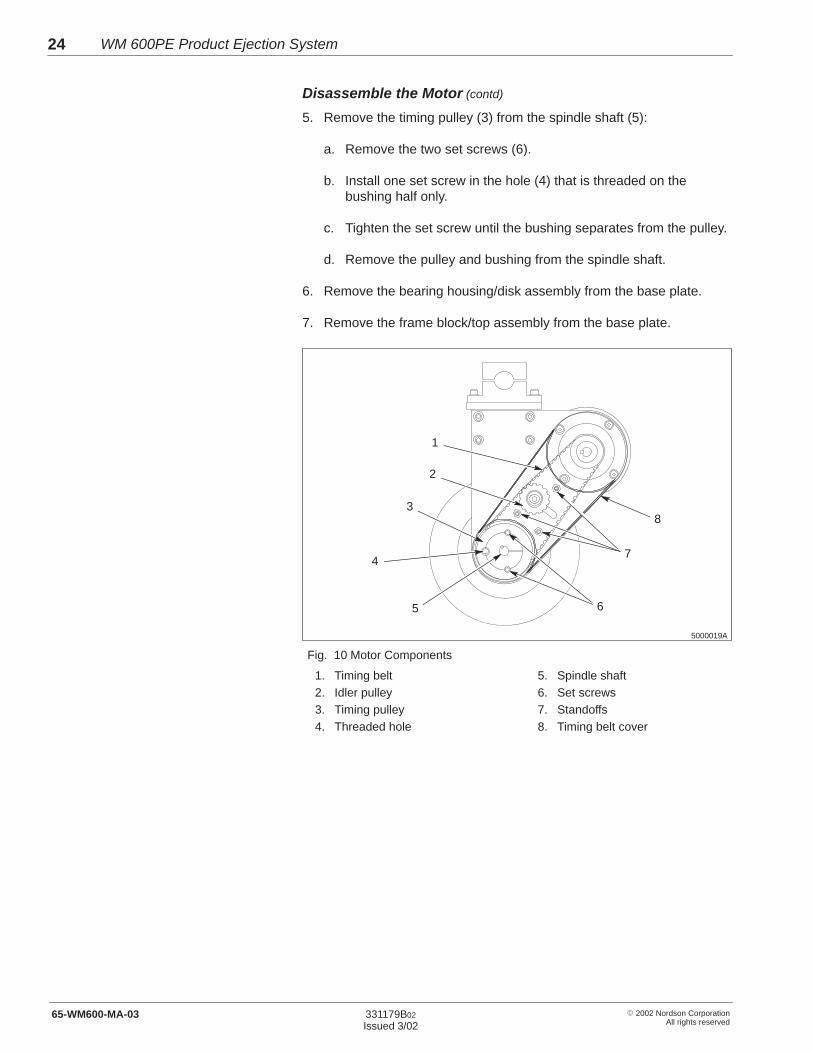
Disassemble the Motor (contd)
5. Remove the timing pulley (3) from the spindle shaft (5):
a. Remove the two set screws (6).
b. Install one set screw in the hole (4) that is threaded on thebushing half only.
c. Tighten the set screw until the bushing separates from the pulley.
d. Remove the pulley and bushing from the spindle shaft.
6. Remove the bearing housing/disk assembly from the base plate.
7. Remove the frame block/top assembly from the base plate.
5000019A
1
2
3
4
5 26
8
7
Fig. 10 Motor Components
1. Timing belt2. Idler pulley3. Timing pulley4. Threaded hole
5. Spindle shaft6. Set screws7. Standoffs8. Timing belt cover

WM 600PE Product Ejection System 25
� 2002 Nordson CorporationAll rights reserved
331179B02
Issued 3/02 65-WM600-MA-03
Assemble the Motor on the Left Side
1. Turn the base plate over and reattach the frame block/top assemblyand the bearing hosing/disk assembly to the base plate.
2. See Figure 10. Install the timing pulley on the spindle:
a. Insert the bushing in the pulley.
b. Line up the threaded halves of the holes in the pulley with thenonthreaded halves of the holes in the bushing as shown inFigure 10.
c. Install the pulley/bushing assembly on the spindle shaft.
d. Alternately tighten the set screws to 20 N�m (175 in.-lb).
3. Install the idler pulley assembly.
4. Install the timing belt cover standoffs.
5. Install the timing belt and motor.
6. Adjust the timing belt alignment. All alignments are acceptableexcept for those shown in Figure 11.
5000008A
Fig. 11 Unacceptable Timing Belt Alignments
7. Adjust the timing belt tension using the idler pulley. When correctlytensioned, the belt will deflect 5 mm (0.19 in.) when 9 N (2 lbf) isapplied midway between the pulleys, as shown in Figure 9.
8. Install the timing belt cover.
WM 600PE Product Ejection System26
� 2002 Nordson CorporationAll rights reserved
331179B02
Issued 3/0265-WM600-MA-03
To place the product ejection system into operation, start up thefolder-gluer and place the motor ON/OFF switch, located on the motorcontrol box, in the ON position. When operation is suspended for theday, shut down the folder-gluer and place the motor ON/OFF switch inthe OFF position.
NOTE: If you wired the product ejector into the folder-gluer run-circuit,you can leave the motor ON/OFF switch in the ON position, except forunit repairs.
CAUTION: Risk of personal injury. Prevent personnel fromstanding in front of ejector where they could be injured byejected cartons.
5. Operation

WM 600PE Product Ejection System 27
� 2002 Nordson CorporationAll rights reserved
331179B02
Issued 3/02 65-WM600-MA-03
The following troubleshooting table describes the kinds of problems youmay encounter and provides corrective actions.
Problem Possible Cause Corrective Action
1. Clamp wheel notresponding tocast-out 1 output fromWM 500 unit orWM 600AL alarm box
Solenoid valve not connected electrically Check the solenoid valve electricalconnections.
No air pressure to solenoid valve Check the air pressure regulator/filterand the air line.
Insufficient air pressure to solenoid valve Make sure the air pressureregulator/filter is set for a minimum of2.8 bar (40 psi).
Failed solenoid valve Replace the solenoid valve.
2. Motor does not run Motor ON/OFF switch in OFF position Place the motor ON/OFF switch in theON position.
Motor protector tripped Reset the motor protector as follows:
1. Place the motor ON/OFF switch inthe OFF position
2. Push the switch beyond the OFFposition and then place the switch inthe ON position.
Fuses blown Check the fuses inside the L1 and Nterminal stations inside the the motorcontrol box. Replace blown fuses.Refer to Parts for the fuse part numbers.
No power to motor Make sure the pilot light on the motorcontrol box turns on when the motorON/OFF switch is in the ON position. Ifit does not, check the motor circuitwiring, circuit breaker, etc.
Failed motor Replace the motor.
6. Troubleshooting
WM 600PE Product Ejection System28
� 2002 Nordson CorporationAll rights reserved
331179B02
Issued 3/0265-WM600-MA-03
Problem Corrective ActionPossible Cause
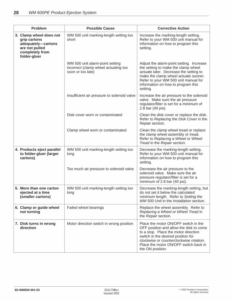
3. Clamp wheel does notgrip cartonsadequately—cartonsare not pulledcompletely fromfolder-gluer
WM 500 unit marking-length setting tooshort
Increase the marking-length setting.Refer to your WM 500 unit manual forinformation on how to program thissetting.
WM 500 unit alarm-point settingincorrect (clamp wheel actuating toosoon or too late)
Adjust the alarm-point setting. Increasethe setting to make the clamp wheelactuate later. Decrease the setting tomake the clamp wheel actuate sooner.Refer to your WM 500 unit manual forinformation on how to program thissetting.
Insufficient air pressure to solenoid valve Increase the air pressure to the solenoidvalve. Make sure the air pressureregulator/filter is set for a minimum of2.8 bar (40 psi).
Disk cover worn or contaminated Clean the disk cover or replace the disk.Refer to Replacing the Disk Cover in theRepair section.
Clamp wheel worn or contaminated Clean the clamp wheel tread or replacethe clamp wheel assembly or tread.Refer to Replacing a Wheel or WheelTread in the Repair section.
4. Products eject parallelto folder-gluer (largercartons)
WM 500 unit marking-length setting toolong
Decrease the marking-length setting.Refer to your WM 500 unit manual forinformation on how to program thissetting.
Too much air pressure to solenoid valve Decrease the air pressure to thesolenoid valve. Make sure the airpressure regulator/filter is set for aminimum of 2.8 bar (40 psi).
5. More than one cartonejected at a time(smaller cartons)
WM 500 unit marking-length setting toolong
Decrease the marking-length setting, butdo not set it below the calculatedminimum length. Refer to Setting theWM 500 Unit in the Installation section.
6. Clamp or guide wheelnot turning
Failed wheel bearings Replace the wheel assembly. Refer toReplacing a Wheel or Wheel Tread inthe Repair section.
7. Disk turns in wrongdirection
Motor direction switch in wrong position Place the motor ON/OFF switch in theOFF position and allow the disk to cometo a stop. Place the motor directionswitch in the desired position forclockwise or counterclockwise rotation.Place the motor ON/OFF switch back inthe ON position.

WM 600PE Product Ejection System 29
� 2002 Nordson CorporationAll rights reserved
331179B02
Issued 3/02 65-WM600-MA-03
Use these repair procedures as directed in the troubleshooting table.
Follow this procedure to replace the disk.
1. Shut down the folder-gluer, turn off the product ejector motor, anddisconnect and lock out electrical power to the ejector.
2. See Figure 12. Remove the four top-frame screws (2) and lift off thetop assembly (1).
3. Remove the flat head screw in the center of the disk. Lift the disk andthe hub up and off the spindle. Remove the hub from the disk andinstall it on the replacement disk. Reinstall the hub and disk.
4. Reinstall the top assembly and resume normal operation.
5000003
4
3
1
2
Fig. 12 Replacing the Disk
1. Top assembly2. Top frame screws
3. Hub4. Disk
7. Repair
Replacing the Disk
WM 600PE Product Ejection System30
� 2002 Nordson CorporationAll rights reserved
331179B02
Issued 3/0265-WM600-MA-03
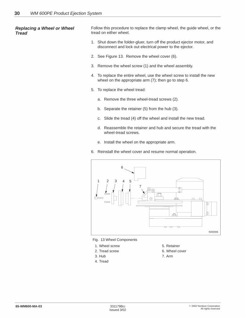
Follow this procedure to replace the clamp wheel, the guide wheel, or thetread on either wheel.
1. Shut down the folder-gluer, turn off the product ejector motor, anddisconnect and lock out electrical power to the ejector.
2. See Figure 13. Remove the wheel cover (6).
3. Remove the wheel screw (1) and the wheel assembly.
4. To replace the entire wheel, use the wheel screw to install the newwheel on the appropriate arm (7); then go to step 6.
5. To replace the wheel tread:
a. Remove the three wheel-tread screws (2).
b. Separate the retainer (5) from the hub (3).
c. Slide the tread (4) off the wheel and install the new tread.
d. Reassemble the retainer and hub and secure the tread with thewheel-tread screws.
e. Install the wheel on the appropriate arm.
6. Reinstall the wheel cover and resume normal operation.
5000006
6
41 2 3 57
Fig. 13 Wheel Components
1. Wheel screw2. Tread screw3. Hub4. Tread
5. Retainer6. Wheel cover7. Arm
Replacing a Wheel or WheelTread
WM 600PE Product Ejection System 31
� 2002 Nordson CorporationAll rights reserved
331179B02
Issued 3/02 65-WM600-MA-03
To order parts, call the Nordson Customer Service Center or contact yourNordson representative. Use the parts lists and accompanyingillustrations in this section to locate and describe parts correctly.
Numbers in the Item column correspond to numbers that identify parts inillustrations following each parts list. The code NS (not shown) indicatesthat a listed part is not illustrated. A dash (—) is used when the partnumber applies to all parts in the illustration.
The six-digit number in the Part column is the Nordson Corporation partnumber. A series of dashes in this column (- - - - - -) means the partcannot be ordered separately.
The Description column gives the part name, as well as its dimensionsand other characteristics when appropriate. Indentions show therelationships between assemblies, subassemblies, and parts.
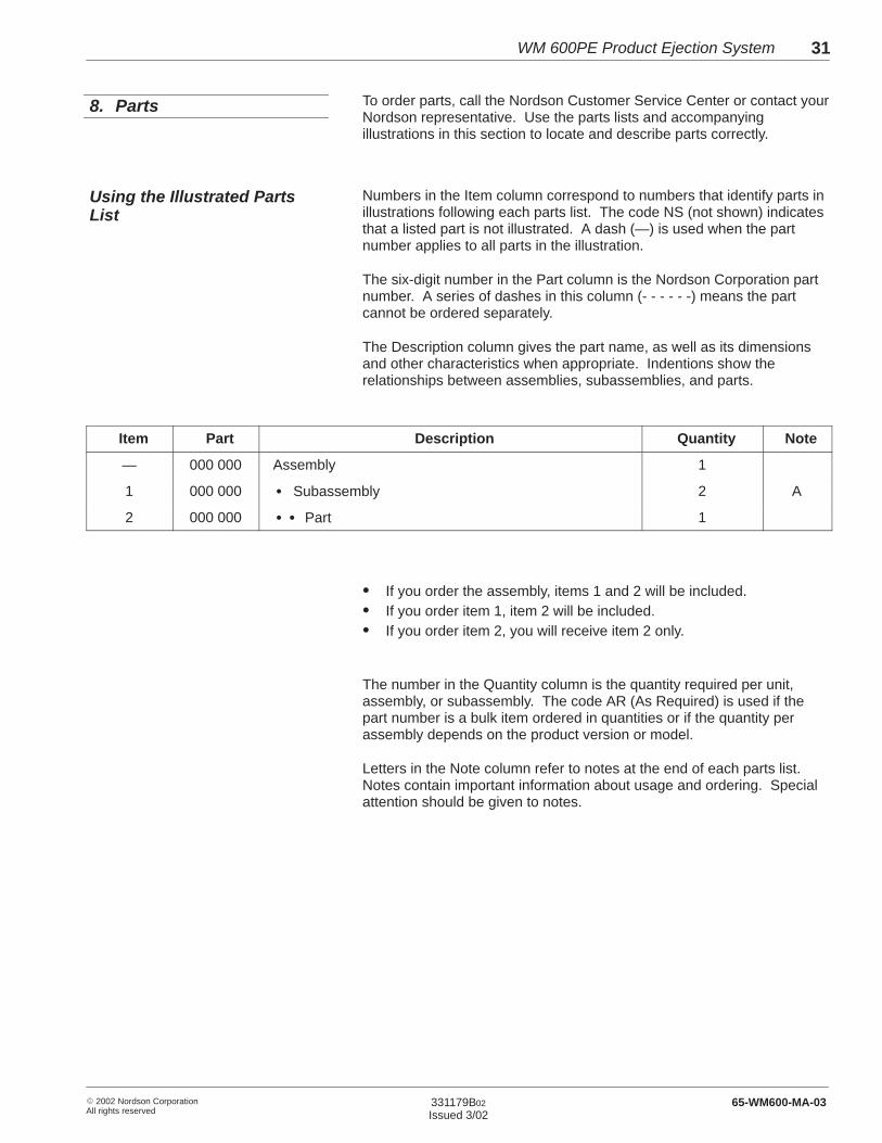
Item Part Description Quantity Note
— 000 000 Assembly 1
1 000 000 � Subassembly 2 A
2 000 000 � � Part 1
� If you order the assembly, items 1 and 2 will be included.� If you order item 1, item 2 will be included.� If you order item 2, you will receive item 2 only.
The number in the Quantity column is the quantity required per unit,assembly, or subassembly. The code AR (As Required) is used if thepart number is a bulk item ordered in quantities or if the quantity perassembly depends on the product version or model.
Letters in the Note column refer to notes at the end of each parts list.Notes contain important information about usage and ordering. Specialattention should be given to notes.
8. Parts
Using the Illustrated PartsList
WM 600PE Product Ejection System32
� 2002 Nordson CorporationAll rights reserved
331179B02
Issued 3/0265-WM600-MA-03
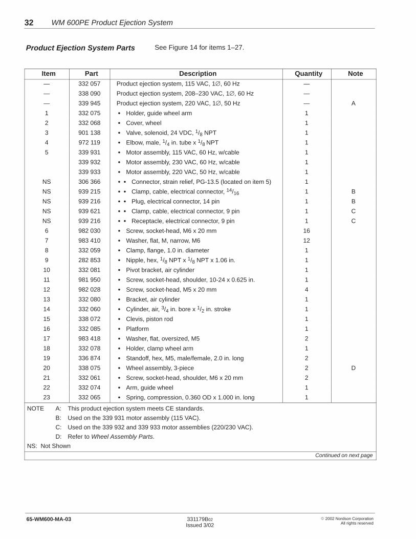
See Figure 14 for items 1–27.
Item Part Description Quantity Note— 332 057 Product ejection system, 115 VAC, 1∅, 60 Hz —
— 338 090 Product ejection system, 208–230 VAC, 1∅, 60 Hz —
— 339 945 Product ejection system, 220 VAC, 1∅, 50 Hz — A
1 332 075 � Holder, guide wheel arm 1
2 332 068 � Cover, wheel 1
3 901 138 � Valve, solenoid, 24 VDC, 1/8 NPT 1
4 972 119 � Elbow, male, 1/4 in. tube x 1/8 NPT 1
5 339 931 � Motor assembly, 115 VAC, 60 Hz, w/cable 1
339 932 � Motor assembly, 230 VAC, 60 Hz, w/cable 1
339 933 � Motor assembly, 220 VAC, 50 Hz, w/cable 1
NS 306 366 � � Connector, strain relief, PG-13.5 (located on item 5) 1
NS 939 215 � � Clamp, cable, electrical connector, 14/16 1 B
NS 939 216 � � Plug, electrical connector, 14 pin 1 B
NS 939 621 � � Clamp, cable, electrical connector, 9 pin 1 C
NS 939 216 � � Receptacle, electrical connector, 9 pin 1 C
6 982 030 � Screw, socket-head, M6 x 20 mm 16
7 983 410 � Washer, flat, M, narrow, M6 12
8 332 059 � Clamp, flange, 1.0 in. diameter 1
9 282 853 � Nipple, hex, 1/8 NPT x 1/8 NPT x 1.06 in. 1
10 332 081 � Pivot bracket, air cylinder 1
11 981 950 � Screw, socket-head, shoulder, 10-24 x 0.625 in. 1
12 982 028 � Screw, socket-head, M5 x 20 mm 4
13 332 080 � Bracket, air cylinder 1
14 332 060 � Cylinder, air, 3/4 in. bore x 1/2 in. stroke 1
15 338 072 � Clevis, piston rod 1
16 332 085 � Platform 1
17 983 418 � Washer, flat, oversized, M5 2
18 332 078 � Holder, clamp wheel arm 1
19 336 874 � Standoff, hex, M5, male/female, 2.0 in. long 2
20 338 075 � Wheel assembly, 3-piece 2 D
21 332 061 � Screw, socket-head, shoulder, M6 x 20 mm 2
22 332 074 � Arm, guide wheel 1
23 332 065 � Spring, compression, 0.360 OD x 1.000 in. long 1
NOTE A: This product ejection system meets CE standards.
B: Used on the 339 931 motor assembly (115 VAC).
C: Used on the 339 932 and 339 933 motor assemblies (220/230 VAC).
D: Refer to Wheel Assembly Parts.
NS: Not Shown
Continued on next page
Product Ejection System Parts
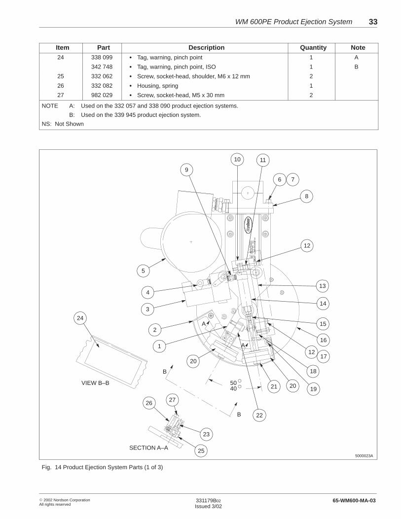
WM 600PE Product Ejection System 33
� 2002 Nordson CorporationAll rights reserved
331179B02
Issued 3/02 65-WM600-MA-03
Item NoteQuantityDescriptionPart24 338 099 � Tag, warning, pinch point 1 A
342 748 � Tag, warning, pinch point, ISO 1 B
25 332 062 � Screw, socket-head, shoulder, M6 x 12 mm 2
26 332 082 � Housing, spring 1
27 982 029 � Screw, socket-head, M5 x 30 mm 2
NOTE A: Used on the 332 057 and 338 090 product ejection systems.
B: Used on the 339 945 product ejection system.
NS: Not Shown
6
8
5
24
14
18
134
3
2
1
20
22
12
9
10 11
7
15
16
12
192021
26 27
23
25
B
B
A
A
SECTION A–A
VIEW B–B �
�5040
5000023A
17
Fig. 14 Product Ejection System Parts (1 of 3)
WM 600PE Product Ejection System34
� 2002 Nordson CorporationAll rights reserved
331179B02
Issued 3/0265-WM600-MA-03
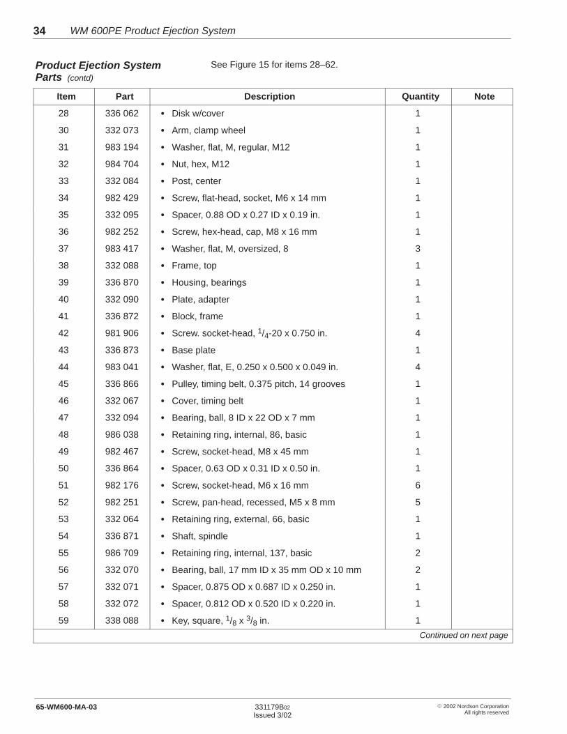
See Figure 15 for items 28–62.
Item Part Description Quantity Note
28 336 062 � Disk w/cover 1
30 332 073 � Arm, clamp wheel 1
31 983 194 � Washer, flat, M, regular, M12 1
32 984 704 � Nut, hex, M12 1
33 332 084 � Post, center 1
34 982 429 � Screw, flat-head, socket, M6 x 14 mm 1
35 332 095 � Spacer, 0.88 OD x 0.27 ID x 0.19 in. 1
36 982 252 � Screw, hex-head, cap, M8 x 16 mm 1
37 983 417 � Washer, flat, M, oversized, 8 3
38 332 088 � Frame, top 1
39 336 870 � Housing, bearings 1
40 332 090 � Plate, adapter 1
41 336 872 � Block, frame 1
42 981 906 � Screw. socket-head, 1/4-20 x 0.750 in. 4
43 336 873 � Base plate 1
44 983 041 � Washer, flat, E, 0.250 x 0.500 x 0.049 in. 4
45 336 866 � Pulley, timing belt, 0.375 pitch, 14 grooves 1
46 332 067 � Cover, timing belt 1
47 332 094 � Bearing, ball, 8 ID x 22 OD x 7 mm 1
48 986 038 � Retaining ring, internal, 86, basic 1
49 982 467 � Screw, socket-head, M8 x 45 mm 1
50 336 864 � Spacer, 0.63 OD x 0.31 ID x 0.50 in. 1
51 982 176 � Screw, socket-head, M6 x 16 mm 6
52 982 251 � Screw, pan-head, recessed, M5 x 8 mm 5
53 332 064 � Retaining ring, external, 66, basic 1
54 336 871 � Shaft, spindle 1
55 986 709 � Retaining ring, internal, 137, basic 2
56 332 070 � Bearing, ball, 17 mm ID x 35 mm OD x 10 mm 2
57 332 071 � Spacer, 0.875 OD x 0.687 ID x 0.250 in. 1
58 332 072 � Spacer, 0.812 OD x 0.520 ID x 0.220 in. 1
59 338 088 � Key, square, 1/8 x 3/8 in. 1
Continued on next page
Product Ejection SystemParts (contd)

WM 600PE Product Ejection System 35
� 2002 Nordson CorporationAll rights reserved
331179B02
Issued 3/02 65-WM600-MA-03
Item NoteQuantityDescriptionPart
60 982 709 � Screw, socket-head, M5 x 10 mm 4
61 984 090 � Nut, hex, lock, torque, M8 1
62 332 077 � Hub 1
5000021A
40
6
33
38
45
43
41
44
61
7
3637
42
37 46
49
48
50
47
52
31
51
37
5354
55
56515758
59
60
28
8 mm(0.31 in.)
30
34
35
32
62
39
Fig. 15 Product Ejection System Parts (2 of 3)

WM 600PE Product Ejection System36
� 2002 Nordson CorporationAll rights reserved
331179B02
Issued 3/0265-WM600-MA-03
See Figure 16 for items 63–71.
Item Part Description Quantity Note
63 109 915 � Key, square, 0.125 x 0.750 in. 1
64 336 867 � Pulley, timing, 0.375 pitch, 24 grooves 1
65 338 092 � Bushing, taper, 1/2 in. bore w/0.13 in. key 1
66 336 869 � Standoff, hex, M5, male/female, 1.26 in. long 3
67 336 865 � Pulley, idler, 0.375 pitch, 14 grooves 1
68 336 868 � Belt, timing, 0.375 pitch, 21.00 pitch length 1
69 - - - - - - � Information plate 1
70 - - - - - - � Rivet, pop, 1/8 x 0.125 in. 2
71 - - - - - - � Motor control box 1 A
72 - - - - - - � Key, square, 1/8 in. 1 B
NS 165 735 � Air regulator/filter, 1/4 NPT 1
NS 901 258 � Gauge, air, 1/8 NPT, 90 psi 1
NS 900 509 � Tubing, polyethylene, 0.250 x 0.40 in. 10 ft
NS 971 265 � Connector, male, 1/4 in. tube x 1/4 NPT 1
NOTE A: Refer to Motor Control Box Parts.
B: This key is supplied with the motor, item 5.
NS: Not Shown
5000022A
70
69
71
68
64
67
66
72
65
63
Fig. 16 Product Ejection System Parts (3 of 3)
Product Ejection SystemParts (contd)

WM 600PE Product Ejection System 37
� 2002 Nordson CorporationAll rights reserved
331179B02
Issued 3/02 65-WM600-MA-03
See Figure 17.
Item Part Description Quantity Note
— 338 075 Wheel assembly, 3 piece — A
1 332 105 � Tread, wheel 1
2 336 860 � Retainer, tread 1
3 982 658 � Screw, socket-head, M3 x 16 mm 3
— 338 093 � Hub assembly, w/bearings — B
4 - - - - - - � � Spacer, 0.50 OD x 0.31 ID x 0.25 in. 1
5 - - - - - - � � Bearing, ball, 8 ID x 22 OD x 7 mm 2
6 - - - - - - � � Hub, wheel 1
NOTE A: Order this part to replace an entire wheel assembly.
B: Order this part to replace the hub assembly only.
ÇÇÇÇÇÇÇÇÇÇÇÇÇÇÇÇÇÇÇÇÇÇÇÇ
ÍÍÍÍÍÍÍÍÍÍÍÍÍÍÍ
ÉÉÉÉÉÉÉÉÉÉÉÉ
5000013A
ÇÇÇÇÇÇÇÇÇÇÇÇÇÇÇÇÇÇÇÇÇÇÇÇÇÇÇÇÇÇ
ÉÉÉÉÉÉÉÉÉÉÉÉ
ÍÍÍÍÍÍÍÍÍÍÍÍÍÍÍ
1
3
5
6
2
4
ÉÉÉ
Fig. 17 Wheel Assembly Parts
Wheel Assembly Parts
WM 600PE Product Ejection System38
� 2002 Nordson CorporationAll rights reserved
331179B02
Issued 3/0265-WM600-MA-03
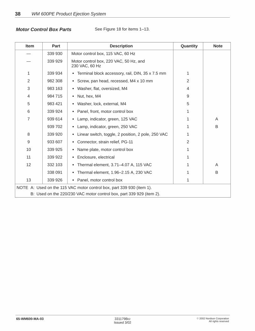
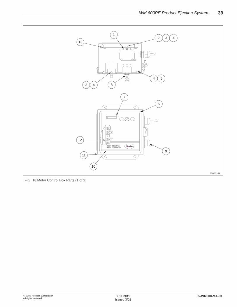
See Figure 18 for items 1–13.
Item Part Description Quantity Note
— 339 930 Motor control box, 115 VAC, 60 Hz
— 339 929 Motor control box, 220 VAC, 50 Hz, and230 VAC, 60 Hz
1 339 934 � Terminal block accessory, rail, DIN, 35 x 7.5 mm 1
2 982 308 � Screw, pan head, recessed, M4 x 10 mm 2
3 983 163 � Washer, flat, oversized, M4 4
4 984 715 � Nut, hex, M4 9
5 983 421 � Washer, lock, external, M4 5
6 339 924 � Panel, front, motor control box 1
7 939 614 � Lamp, indicator, green, 125 VAC 1 A
939 702 � Lamp, indicator, green, 250 VAC 1 B
8 339 920 � Linear switch, toggle, 2 position, 2 pole, 250 VAC 1
9 933 607 � Connector, strain relief, PG-11 2
10 339 925 � Name plate, motor control box 1
11 339 922 � Enclosure, electrical 1
12 332 103 � Thermal element, 3.71–4.07 A, 115 VAC 1 A
338 091 � Thermal element, 1.96–2.15 A, 230 VAC 1 B
13 339 926 � Panel, motor control box 1
NOTE A: Used on the 115 VAC motor control box, part 339 930 (item 1).
B: Used on the 220/230 VAC motor control box, part 339 929 (item 2).
Motor Control Box Parts
WM 600PE Product Ejection System 39
� 2002 Nordson CorporationAll rights reserved
331179B02
Issued 3/02 65-WM600-MA-03
5000016A
8
1
6
9
10
12
132
11
7
4 5
43
3 4
Fig. 18 Motor Control Box Parts (1 of 2)

WM 600PE Product Ejection System40
� 2002 Nordson CorporationAll rights reserved
331179B02
Issued 3/0265-WM600-MA-03
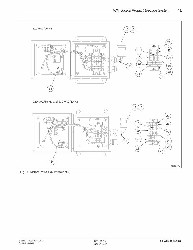
See Figure 19 for items 14–27.
Item Part Description Quantity Note
14 332 102 � Starter, motor, fractional horsepower 1
15 939 215 � Clamp, cable, electrical connector, 14/16 1 A
939 621 � Clamp, cable, electrical connector, 9 pin 1 B
16 939 555 � Receptacle, electrical connector, 14 pin 1 A
933 315 � Plug, electrical connector, 9 pin 1 B
17 - - - - - - � Wire group 1
18 165 395 � Jumper, 2 pole, 6.5 mm 2
19 161 781 � Partition, 1.5 mm thick 1
20 221 695 � End cap, fuse holder 1
21 161 778 � Terminal block, ground clamp 2
22 322 538 � Marker, L1, L2, L3, N, GND 3
23 161 787 � Terminal block feed through 6 C
24 161 779 � Marker, 6.5 mm, 1–50 2
25 939 941 � Fuse, 6.3 A 2 A
939 751 � Fuse, 4 A 2 B
26 221 693 � Fuse holder 2
27 169 706 � Marker, L1, L2, L3, N, PE 1
NOTE A: Used on the 115 VAC motor control box, part 339 930 (item 1).
B: Used on the 220/230 VAC motor control box, part 339 929 (item 2).
C: For the 220/230 VAC motor control box (item 2), this quantity is 7.
Motor Control Box Parts (contd)
WM 600PE Product Ejection System 41
� 2002 Nordson CorporationAll rights reserved
331179B02
Issued 3/02 65-WM600-MA-03
5000017A
115 VAC/60 Hz
220 VAC/50 Hz and 230 VAC/60 Hz
15
17
14
16
14
15 16
17
18
19
20
21
22
23
24
27
25
26
18
19
20
21
22
23
24
27
25
26
Fig. 19 Motor Control Box Parts (2 of 2)

WM 600PE Product Ejection System42
� 2002 Nordson CorporationAll rights reserved
331179B02
Issued 3/0265-WM600-MA-03
Nordson Corporation recommends storing the following spare parts.
Part Description Note
332 105 Tread, wheel
336 962 Disk w/cover
939 941 Fuse, 6.3 A, 115 VAC motor control box
939 751 Fuse, 4 A, 220/230 VAC motor control box
Recommended Spare Parts

WM 600PE Product Ejection System 43
� 2002 Nordson CorporationAll rights reserved
331179B02
Issued 3/02 65-WM600-MA-03
The following wiring diagrams are provided for your reference as needed.
5000012A
M
GND 1 2 3 4 5 8
1 3 2 4 5 6
VIEW A
A A
37
1114
148
12132456
GRN/YEL
1324567
123458
GROUND SCREW
MOTOR CABLE CONNECTION CHART
CABLE CONNECTORPIN NO.
MOTORWIRE NO.
Fig. 20 Motor Assembly Wiring Diagram for the 115 VAC/60 Hz Product Ejector
5000011A
369
147
M
GND 1 2 3 4 5 8
1 2 3 4 5 6
VIEW A
A A
123456
GRN/YEL
1234567
123458
GROUND SCREW
MOTOR CABLE CONNECTION CHART
CABLE CONNECTORPIN NO.
MOTORWIRE NO.
Fig. 21 Motor Assembly Wiring Diagram for the 220 VAC/50 Hz and 230 VAC/60 Hz Product Ejectors
9. Wiring Diagrams
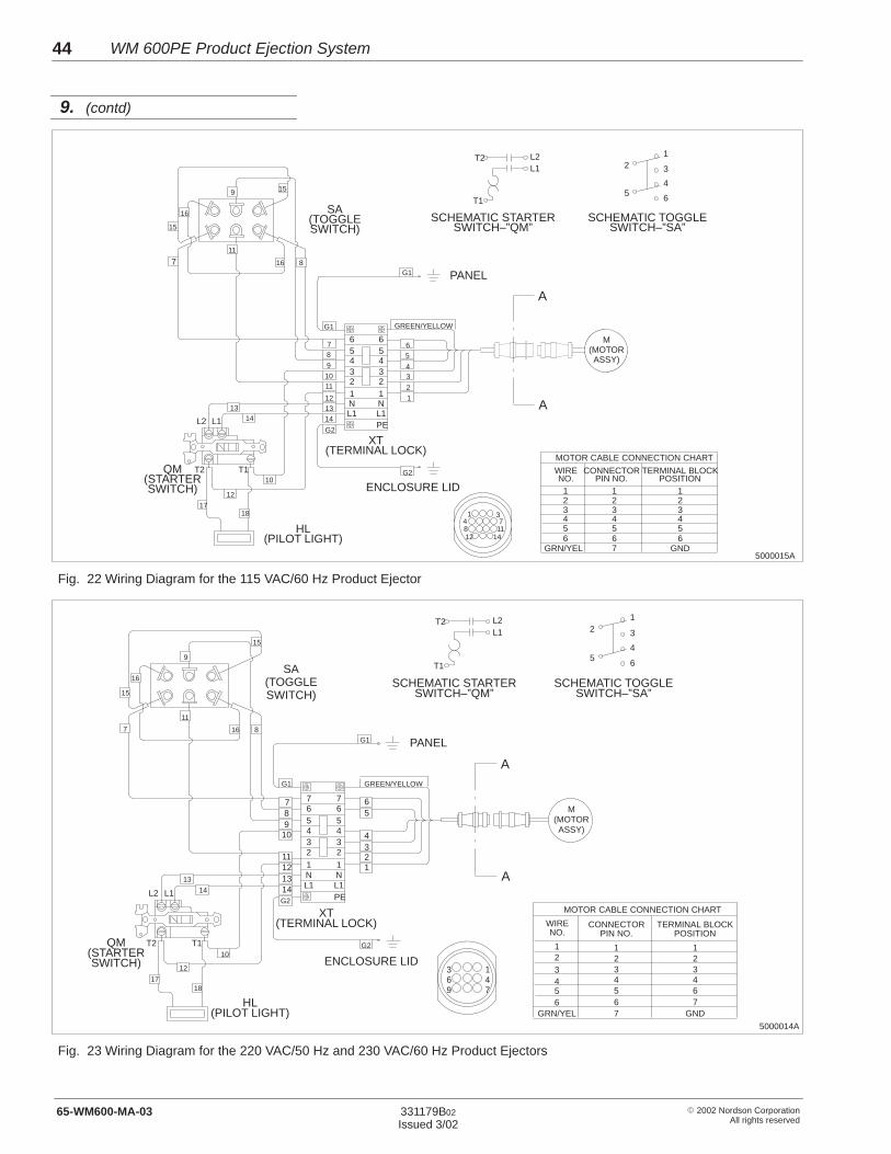
WM 600PE Product Ejection System44
� 2002 Nordson CorporationAll rights reserved
331179B02
Issued 3/0265-WM600-MA-03
5000015A
T2 L2L1
T15 6
12 3
10
12
1718
G1
G2
SA(TOGGLESWITCH)
PANEL
XT(TERMINAL LOCK)
ENCLOSURE LID
QM(STARTERSWITCH)
HL(PILOT LIGHT)
T1T2
L1L2G2
141312
11
GREEN/YELLOW
G1
65
4
1
2
3
1314
10
9
87
654
123
N
PEL1
654
123
NL1
711
16
159
16
15
8
A
A
M(MOTORASSY)
123456
GRN/YEL
1234567
123456
GND
MOTOR CABLE CONNECTION CHART
WIRENO.
CONNECTORPIN NO.
TERMINAL BLOCKPOSITION
4
SCHEMATIC STARTERSWITCH–”QM”
SCHEMATIC TOGGLESWITCH–”SA”
1 34 78 1112 14
Fig. 22 Wiring Diagram for the 115 VAC/60 Hz Product Ejector
GREEN/YELLOW
5000014A
T2 L2L1
T15 6
12 3
10
12
1718
G1
G2
SA(TOGGLESWITCH)
PANEL
XT(TERMINAL LOCK)
ENCLOSURE LID
QM(STARTERSWITCH)
HL(PILOT LIGHT)
T1T2
L1L2G2
14131211
G1
65
4
123
13
14
10987 7
654
123
N
PEL1
7654
123
NL1
7
11
16
15
9
16
15
8
A
A
M(MOTORASSY)
123456
GRN/YEL
1234567
123467
GND
MOTOR CABLE CONNECTION CHART
WIRENO.
CONNECTORPIN NO.
TERMINAL BLOCKPOSITION
4
SCHEMATIC STARTERSWITCH–”QM”
SCHEMATIC TOGGLESWITCH–”SA”
3 147
69
Fig. 23 Wiring Diagram for the 220 VAC/50 Hz and 230 VAC/60 Hz Product Ejectors
9. (contd)

DECLARATION of CONFORMITY
(For CE-Certified Adhesive/Sealant Application Equipment)
PRODUCT:
WM 600PE Product Ejection System
APPLICABLE DIRECTIVES:
98/37/EC (Machinery Directive)73/23/EEC (Low Voltage Directive)
STANDARDS USED TO VERIFY COMPLIANCE:
EN292EN60204-1
PRINCIPLES:
This product has been manufactured according to good engineering practice.
The product specified conforms to the directive and standards described above.
Date: 15 February 2002
Don McLaneSenior Vice President
Nordson Corporation � Duluth, Georgia DOC 019