WJ JEEP 4” WITH CONTROL ARM DROPS - ntwonline.com · WJ JEEP 4” WITH CONTROL ARM DROPS Thank...
12
WJ JEEP 4” WITH CONTROL ARM DROPS Thank you for choosing Rough Country for all your suspension needs. Rough Country recommends a certified technician install this system. In addition to these instructions, professional knowledge of disassemble/reassembly procedures as well as post installation checks must be known. Attempts to install this system without this knowledge and expertise may jeopardize the integrity and/or operating safety of the vehicle. Please read instructions before beginning installation. Check the kit hardware against the kit content list. Be sure you have all needed parts and know where they go. Also please review tools needed list and make sure you have the nec- essary tools to install this kit. PRODUCT USE INFORMATION As a general rule, the taller a vehicle is, the easier it will roll. Seat belts and shoulder harnesses should be worn at all times. Avoid situations where a side rollover may occur. Generally, braking performance and capability are decreased when larger/heavier tires and wheels are used. Take this into consideration while driving. Do not add, alter, or fabricate any factory or after-market parts to increase vehicle height over the intended height of the Rough Country product purchased. Mixing component brands is not recommended. Due to differences in manufacturing, dimension and inflated measurements, tire and wheel combinations should be test fit prior to installation. This suspension system was developed using a 265 / 75R-16 tire with factory wheels. If bigger/ wider tire are used with the factory wheels or factory offset wheels you must carefully check the clearance during turning between the tires and the lower control arm and the front sway bar link before driving. Installing wider than recom- mended tires can cause the tire to come in contact with the rear shock. Always double check for clearance on all tire / wheel packages. With the installation of all lift kits and larger tires it is important to check the condition of your steering stabilizer. If the stabilizer is worn or is leaking it should be replaced. Steering stabilizers are designed to restrain “bump steer” and front- end vibration, giving added life to tires, ball joints, and other steering components. A large bore off-road stabilizer kit is highly recommended for vehicles equipped with larger tires, please contact your Rough Country distributor for details. We hope installing your Rough Country lift kit is a positive experience. Please note that variations in construc- tion and assembly in the vehicle manufacturing process will virtually ensure that some parts may seem difficult to install. If you are uncertain about some aspect of the installation process, please feel free to call our tech support department at 800-222-7023. We do not recommend that you modify the Rough Country parts in any way as this will void any warranty expressed or implied. IMPORTANT PRE—INSTALLATION INSTRUCTIONS Prior to beginning this installation it is always good to use a penetrating oil and spray all fasteners that will be removed. Typically the cross member, control arm bolts and the pitman arm are difficult to remove without hav- ing done this step. 92169820 Tools Needed: • 13mm Socket / Wrench • 14mm Socket / Wrench • 15mm Socket / Wrench • 18mm Socket / Wrench • 19mm Socket / Wrench • 21mm Socket / Wrench • 22mm Socket / Wrench • 33mm Socket Torque Specs: Size Grade 5 Grade 8 3/8” 30 ft/lbs 35 ft/lbs 7/16” 45 ft/lbs 60 ft/lbs 1/2” 65 ft/lbs 90 ft/lbs 9/16” 95 ft/lbs 130 ft/lbs 5/8” 135 ft/lbs 175 ft/lbs Class 8.8 Class 10.9 8MM 18ft/lbs 23 ft/lbs 10MM 32ft/lbs 45ft/lbs 12MM 55ft/lbs 75ft/lbs 14MM 85ft/lbs 120ft/lbs • Pitman Arm Puller • Drill Motor • 3/8” Drill Bit • Pry Bar • Floor Jack • Jack Stands • Spring Compressor • Lithium Based Grease
Transcript of WJ JEEP 4” WITH CONTROL ARM DROPS - ntwonline.com · WJ JEEP 4” WITH CONTROL ARM DROPS Thank...

WJ JEEP 4” WITH CONTROL ARM DROPS Thank you for choosing Rough Country for all your suspension needs.
Rough Country recommends a certified technician install this system. In addition to these instructions, professional knowledge of disassemble/reassembly procedures as well as post installation checks must be known. Attempts to install this system without this knowledge and expertise may jeopardize the integrity and/or operating safety of the vehicle.
Please read instructions before beginning installation. Check the kit hardware against the kit content list. Be sure you have all needed parts and know where they go. Also please review tools needed list and make sure you have the nec-essary tools to install this kit.
PRODUCT USE INFORMATION
As a general rule, the taller a vehicle is, the easier it will roll. Seat belts and shoulder harnesses should be worn at all times. Avoid situations where a side rollover may occur.
Generally, braking performance and capability are decreased when larger/heavier tires and wheels are used. Take this into consideration while driving. Do not add, alter, or fabricate any factory or after-market parts to increase vehicle height over the intended height of the Rough Country product purchased. Mixing component brands is not recommended.
Due to differences in manufacturing, dimension and inflated measurements, tire and wheel combinations should be test fit prior to installation. This suspension system was developed using a 265 / 75R-16 tire with factory wheels. If bigger/wider tire are used with the factory wheels or factory offset wheels you must carefully check the clearance during turning between the tires and the lower control arm and the front sway bar link before driving. Installing wider than recom-mended tires can cause the tire to come in contact with the rear shock. Always double check for clearance on all tire / wheel packages.
With the installation of all lift kits and larger tires it is important to check the condition of your steering stabilizer. If the stabilizer is worn or is leaking it should be replaced. Steering stabilizers are designed to restrain “bump steer” and front-end vibration, giving added life to tires, ball joints, and other steering components. A large bore off-road stabilizer kit is highly recommended for vehicles equipped with larger tires, please contact your Rough Country distributor for details.
We hope installing your Rough Country lift kit is a positive experience. Please note that variations in construc-tion and assembly in the vehicle manufacturing process will virtually ensure that some parts may seem difficult to install. If you are uncertain about some aspect of the installation process, please feel free to call our tech support department at 800-222-7023. We do not recommend that you modify the Rough Country parts in any way as this will void any warranty expressed or implied.
IMPORTANT PRE—INSTALLATION INSTRUCTIONS Prior to beginning this installation it is always good to use a penetrating oil and spray all fasteners that will be removed. Typically the cross member, control arm bolts and the pitman arm are difficult to remove without hav-ing done this step.
92169820
Tools Needed: • 13mm Socket / Wrench • 14mm Socket / Wrench • 15mm Socket / Wrench • 18mm Socket / Wrench • 19mm Socket / Wrench • 21mm Socket / Wrench • 22mm Socket / Wrench • 33mm Socket
Torque Specs:
Size Grade 5 Grade 8 3/8” 30 ft/lbs 35 ft/lbs 7/16” 45 ft/lbs 60 ft/lbs 1/2” 65 ft/lbs 90 ft/lbs 9/16” 95 ft/lbs 130 ft/lbs 5/8” 135 ft/lbs 175 ft/lbs Class 8.8 Class 10.9 8MM 18ft/lbs 23 ft/lbs 10MM 32ft/lbs 45ft/lbs 12MM 55ft/lbs 75ft/lbs 14MM 85ft/lbs 120ft/lbs
• Pitman Arm Puller • Drill Motor • 3/8” Drill Bit • Pry Bar • Floor Jack • Jack Stands • Spring Compressor • Lithium Based Grease
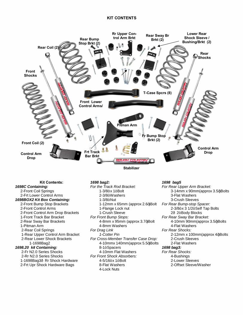
Kit Contents: 1698C Containing: 2-Front Coil Springs 2-Frt Lower Control Arms 1698BOX2 Kit Box Containing: 2-Front Bump Stop Brackets 2-Front Control Arms 2-Front Control Arm Drop Brackets 1-Front Track Bar Bracket 2-Rear Sway Bar Brackets 1-Pitman Arm 2-Rear Coil Springs 1-Rear Upper Control Arm Bracket 2-Rear Lower Shock Brackets 1-1698Bag2 1698.20 kit Containing: 2-Fr N2.0 Series Shocks 2-Rr N2.0 Series Shocks 1-1698Bag3—Rr Shock Hardware 2-Frt Upr Shock Hardware Bags
KIT CONTENTS
Rear Coil (2)
1698 bag2: For the Track Rod Bracket: 1-3/8” x 1” Bolt 2-3/8” Washers 1-3/8” Nut 1-12mm x 65mm (approx 2.6”)Bolt 1-Flange Lock nut 1-Crush Sleeve For Front Bump Stops: 4-8mm x 95mm (approx 3.7”)Bolt 4-8mm Washers For Drag Link 1-Cotter Pin For Cross-Member Transfer Case Drop: 4-10mmx 140mm(approx 5.5”)Bolts 8-1” Spacers 4-10mm Flat Washers For Front Shock Absorbers: 4-5/16” x 1” Bolt 8-Flat Washers 4-Lock Nuts
1698 bag5 For Rear Upper Arm Bracket: 3-14mm x 90mm(approx 3.5”)Bolts 3-Flat Washers 3-Crush Sleeves For Rear Bump-stop Spacer: 2-3/8” x 3 1/2” Self Tap Bolts 2—2” Body Blocks For Rear Sway Bar Bracket: 4-10mm 90mm(approx 3.5”)Bolts 4-Flat Washers For Rear Shocks: 2-12mm x 100mm(approx 4”)Bolts 2-Crush Sleeves 2-Flat Washers 1698 bag3: For Rear Shocks: 4-Bushings 2-Lower Sleeves 2-Offset Sleeve/Washer
Rear Shocks
Front Shocks
Front Coil (2)
Frt Track Bar Brkt
Pitman Arm
Rr Upper Con-trol Arm Brkt Rear Sway Br
Brkt (2)
T-Case Spcrs (8)
Front Lower Control Arms/
Fr Bump Stop Brkt (2)
Lower Rear Shock Sleeve /
Bushing/Brkt (2) Rear Bump
Stop Brkt (2)
Control Arm Drop
Control Arm Drop
Stabilizer

FRONT INSTALLATION INSTRUCTIONS
1. Chock the rear wheels and jack up the front of the vehicle and support the vehicle with jack stands. 2. Support the front axle with a floor jack. 3. Remove the lower sway bar link bolt using a 15mm & 18mm wrench. See Photo 1. Retain hardware for reuse. 4. Remove the shocks using a 15mm wrench/socket for the top mount and a 13mm wrench/socket for the bottom
mount. 5. Lower the axle using the floor jack and remove the coil springs. 6. Remove the stock lower control arm using a 21mm wrench/socket. Retain factory hardware for re-use See Photo 2.
7. Install lower control arm drop bracket using the factory control arm bolt. See Photo 3. 8. Slide the new supplied flag nut into the unibody and align the nut with hole. See Photo 4.
9. Raise the back of the control arm drop bracket and secure with the supplied 1/2” x 1.0” bolts and tighten with a 19mm and a 21mm for the stock bolt. See Photo 4.
10. Install the new lower control arm in the drop bracket using the supplied cam bolt and hand tighten. See Photo 6.
Photo 1
Remove Lower Sway Bar Link from Axle Mount Remove Lower Control Arm
Install New Lower Control Arm Drop Bracket
Photo 3
Photo 2
Photo 4
Photo 5 Photo 6
Insert Flag Nut
Secure with 1/2 x 1” Bolt Install Lower Control Arm

Remove Front Factory Bump Stop Remove Factory Bump Stop Mount
11. Raise the lower control arm and insert the factory bolt in the axle end. Hand tighten. See photo 7. 12. Remove the cotter pin and nut from the pitman arm using a 19mm wrench. Retain nut for reuse. 13. Strike the arm as shown in Photo 8 to dislodge the drag link.
14. Using a pry bar, remove the bump stop from the factory cup. See Photo 9. 15. Next remove the bump stop mounts using a 13mm wrench. See Photo 10.
Photo 7 Photo 8
Remove Tie Rod from Pitman Arm
Photo 9 Photo 10

16. Remove the track bar using a 19mm wrench/socket from the driver side mount. See Photo 11. 17. Mark the pitman arm in the center of the arm and steering box to ensure the new pitman arm is properly aligned and
remove the pitman arm using a 33mm socket as shown in Photo 12. Note: A pitman arm puller may be needed.
18. Using the mark on the splines of the steering box install the new pitman arm centered of the mark and arm. Tighten using a 33mm socket. Proper placement of the pitman arm on the splines of the steering box is very important for alignment purposes. See Photo 13.
19. Remove the engine mount bolts with a 15mm socket. Install the new track bar bracket and secure using the supplied 10mm x 110mm bolts. Mark the lower hole location and remove the bracket. Next drill the marked hole with a 7/16” drill bit. See Photo 14.
20. Reinstall the track bar bracket with the supplied 10mm and 7/16’ bolts. Tighten with a 16mm and 17mm socket. See Photo 14 & 15.
21. Install the factory track bar bolt in the stock location with the supplied crush sleeve. Hand tighten. See Photo 11. 22. Install the new bump stop mounts with the supplied 8mm x 95mm (approx 3.75”)bolts and washers from Bag2 using
a 13mm wrench/socket. See Photo 16. Reinstall the factory rubber bump stops into the factory bump stop cups.
Install Crush Sleeve On Factory Bolt
Photo 11 Photo 12
Photo 13 Photo 14
Photo 15 Photo 16
Mark pitman and steering box splines Remove Track Rod from Driver Side
Install New Drop Pitman Arm Noting Orientation Install Front Track Rod Bracket and Drill
Install Bump Stop Bracket

23. Install the new front coil spring using a coil spring compressor. On lower surface make sure coil end is rotated to stop and on upper mount re-use stock rubber coil isolator.
24. Install the new shock absorbers using the supplied 5/16” x 1” bolts in bag 2, washers and nuts on the bottom bar pin mount. *Note* 2.2 shock mount body up and N2.0 shock mount body down. Tighten using a 14mm wrench at the top using supplied stem bushings, washers and nuts and a 13mm wrench on the bottom.
25. Install the tires and wheels and tighten to factory specifications. 26. Jack up the vehicle and remove the jack stands. 27. Repeat steps on opposite side of vehicle. 28. Lower the vehicle to the ground. 29. Reinstall the sway bar links on the axle using the factory hardware. Tighten using a 15mm & 18mm socket / wrench. 30. Tighten the lower control arm hardware using a 21mm socket/wrench to factory specifications 31. Support the transmission cross member using a floor jack and remove the 4 bolts on each side using a 15mm
socket. See Photo 17. 32. Lower cross member carefully leaving bolts installed but loose on one side. Install the transmission cross member
spacers as shown in Photo 18 and secure with the supplied 10mm x 140mm(approx. 5.5”) bolts and washers from Bag2 and re-using the stock outside factory bolts on the inside mount. Repeat steps on other side.
33. Install the track bar with supplied 12mm x 65mm (approx 2.6”) bolt & flange locknut from Bag2,. Tighten using a 18mm / 19mm socket / wrench. Do not use a flat washer. See Photo 19.
34. Install the drag link in the new pitman arm with factory castle nut and tighten using a 19mm wrench to factory specifi-cations. Install supplied cotter pin from Bag2. See Photo 20.
Photo 19 Photo 20
Photo 17 Photo 18
Re-Use Stock Outer Bolt On Inner Holes
Install the Track Rod in the Bracket Install the Tie Rod in the Pitman Arm
Remove Bolts from Cross Member Install Cross Member Spacers
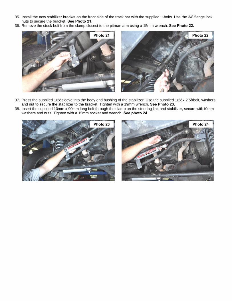
35. Install the new stabilizer bracket on the front side of the track bar with the supplied u-bolts. Use the 3/8 flange lock nuts to secure the bracket. See Photo 21.
36. Remove the stock bolt from the clamp closest to the pitman arm using a 15mm wrench. See Photo 22.
37. Press the supplied 1/2” sleeve into the body end bushing of the stabilizer. Use the supplied 1/2” x 2.5” bolt, washers, and nut to secure the stabilizer to the bracket. Tighten with a 19mm wrench. See Photo 23.
38. Insert the supplied 10mm x 90mm long bolt through the clamp on the steering link and stabilizer, secure with10mm washers and nuts. Tighten with a 15mm socket and wrench. See photo 24.
Photo 21 Photo 22
Photo 23 Photo 24

REAR INSTALLATION INSTRUCTIONS
1. Chock the front tires and jack up the rear of the vehicle. Support the rear with jack stands. 2. Remove the rear shocks using a 15mm and 18mm wrench/socket. 3. Remove the top sway bar bolt using a 15mm wrench/socket. See Photo 1. Retain the factory hardware for reuse. 4. Using the floor jack, lower the rear end and remove the coil springs. 5. Using a 21mm socket remove the 3 bolts that secure the upper arm to the differential. See Photo 2.
6. Remove the e-brake and brake line cable from the upper control arm using a 10mm socket to allow the control arm spacer to be installed in the next step. See Photo 3.
7. Slighlty lower rear axle enough to allow installation of control arm bracket. Install the upper control arm bracket us-ing the supplied crush sleeves, and 14mm x 90mm (approx 3.5”) bolts from Bag5. Tighten using a 22mm socket. See Photo 4.
8. Install the bump stop using the supplied body puck and 3/8” x 3 1/2” self tapping bolts from Bag5. See Photo 5. (On vehicles with Up Country suspension remove the factory bump stop spacer. )
9. Remove the sway bar brackets from the vehicle using a 15mm wrench/socket. See Photo 6.
Photo 4 Photo 3
Photo 2 Photo 1
Photo 5 Photo 6
Remove Sway Bar Link from the Frame Remove the Upper Arm from Center of Axle
Remove the Brake Line Bracket from the Upper Arm Install Upper Arm Spacer Bracket
Install Bump Stop Spacer Remove Upper Sway Bar Bracket From Frame
Crush Sleeves (3)
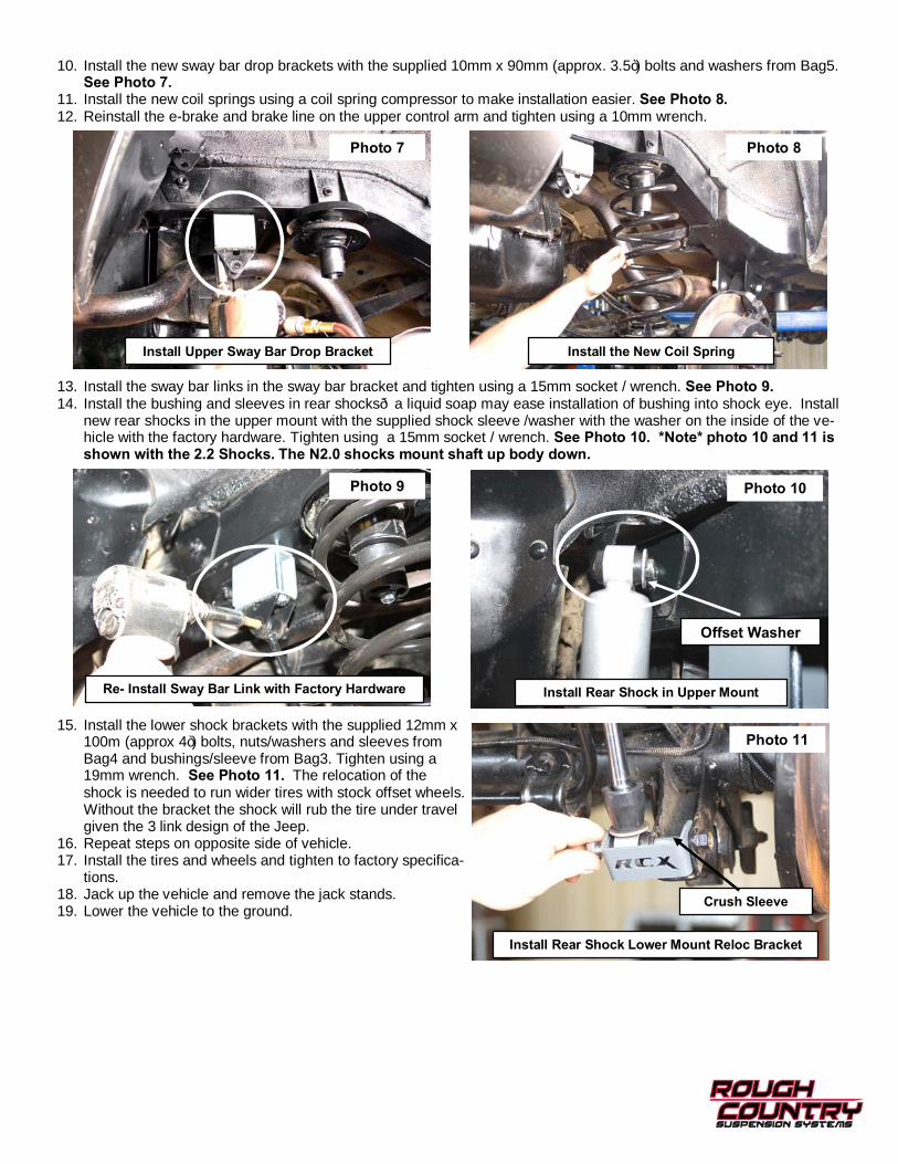
10. Install the new sway bar drop brackets with the supplied 10mm x 90mm (approx. 3.5”) bolts and washers from Bag5. See Photo 7.
11. Install the new coil springs using a coil spring compressor to make installation easier. See Photo 8. 12. Reinstall the e-brake and brake line on the upper control arm and tighten using a 10mm wrench.
13. Install the sway bar links in the sway bar bracket and tighten using a 15mm socket / wrench. See Photo 9. 14. Install the bushing and sleeves in rear shocks—a liquid soap may ease installation of bushing into shock eye. Install
new rear shocks in the upper mount with the supplied shock sleeve /washer with the washer on the inside of the ve-hicle with the factory hardware. Tighten using a 15mm socket / wrench. See Photo 10. *Note* photo 10 and 11 is shown with the 2.2 Shocks. The N2.0 shocks mount shaft up body down.
15. Install the lower shock brackets with the supplied 12mm x 100m (approx 4”) bolts, nuts/washers and sleeves from Bag4 and bushings/sleeve from Bag3. Tighten using a 19mm wrench. See Photo 11. The relocation of the shock is needed to run wider tires with stock offset wheels. Without the bracket the shock will rub the tire under travel given the 3 link design of the Jeep.
16. Repeat steps on opposite side of vehicle. 17. Install the tires and wheels and tighten to factory specifica-
tions. 18. Jack up the vehicle and remove the jack stands. 19. Lower the vehicle to the ground.
Photo 7 Photo 8
Photo 9 Photo 10
Crush Sleeve
Photo 11
Install Upper Sway Bar Drop Bracket Install the New Coil Spring
Re- Install Sway Bar Link with Factory Hardware Install Rear Shock in Upper Mount
Install Rear Shock Lower Mount Reloc Bracket
Offset Washer


POST INSTALLATION
1. Check all fasteners for proper torque. Check to ensure there is adequate clearance between all rotating, mobile, fixed and heated members. Check steering for interference and proper working order. Test brake system.
2. Perform steering sweep. The distance between the tire sidewall and the brake hose must be checked closely. Cycle the steering from full turn to full turn to check for clearance. Failure to perform inspections may result in component failure.
3. An alignment by a certified alignment professional with experience in aligning lifted vehicles must be performed. Align vehicle to factory specifications.
4. Readjust headlights to proper settings. 5. Check hardware after the first 500 miles and then every 1000 miles.
INSTALLING DEALER - it is your responsibility to install the warning decal and forward these installation instructions on to the vehicle owner for review. These instructions should be kept in the vehicle for its service life.
Thank you for purchasing a Rough Country lift for your Jeep.
Adjustable front track bar
Front sway bar dis-connects
Dual stabilizer
Rough Country WJ Accessories


![jeep willys manual jeep militar [jipenet]](https://static.fdocuments.us/doc/165x107/5571f31d49795947648d86b9/jeep-willys-manual-jeep-militar-jipenet.jpg)

![[PPT]Slide 1 · Web viewSSPC-SP WJ-1/NACE WJ-1, Clean to Bare Substrate SSPC-SP WJ-2/NACE WJ-2, Very Thorough Cleaning SSPC-SP WJ-3/NACE WJ-3, Thorough Cleaning SSPC-SP WJ-4/NACE](https://static.fdocuments.us/doc/165x107/5b191e557f8b9a46258c50b2/pptslide-1-web-viewsspc-sp-wj-1nace-wj-1-clean-to-bare-substrate-sspc-sp.jpg)