with third parties. - Music Electronics Forum
32
Service Documents Confidential, for authorized service technicians only! Do not disclose this information to or share these documents with third parties. Vertraulich! Nur für autorisierte Servicetechniker! Nicht zur Weitergabe an Dritte freigegeben! TECHNICAL SERVICE: Stamer Musikanlagen GmbH • Magdeburger Str. 8 • 66606 St.Wendel • Germany Music & Sales P.E. GmbH • Leipziger Str. 3 • 66606 St.Wendel • Germany Note! The components used in this product - particularly parts affecting safety as well as speakers and transformers - were developed and manufactured to certain specifications. Please use original spare parts only to ensure the product remains fully functional and safe. Achtung! Die in diesem Produkt verwendeten Komponenten, insbeson- dere sicherheitsrelevante Teile, Lautsprecher und Transforma- toren wurden nach spezifischen Vorgaben entwickelt und ge- fertigt. Bitte benutzen Sie ausschließlich Original-Ersatzteile – nur so ist die volle Funktionalität und Sicherheit gewährleistet.
Transcript of with third parties. - Music Electronics Forum

Service DocumentsConfidential, for authorized service technicians only!
Do not disclose this information to or share these documentswith third parties.
Vertraulich! Nur für autorisierte Servicetechniker!Nicht zur Weitergabe an Dritte freigegeben!
TECHNICAL SERVICE:
Stamer Musikanlagen GmbH • Magdeburger Str. 8 • 66606 St.Wendel • Germany
Music & Sales P.E. GmbH • Leipziger Str. 3 • 66606 St.Wendel • Germany
Note!The components used in this product - particularly parts
affecting safety as well as speakers and transformers -
were developed and manufactured to certain specifications.
Please use original spare parts only to ensure the product
remains fully functional and safe.
Achtung!Die in diesem Produkt verwendeten Komponenten, insbeson-
dere sicherheitsrelevante Teile, Lautsprecher und Transforma-
toren wurden nach spezifischen Vorgaben entwickelt und ge-
fertigt. Bitte benutzen Sie ausschließlich Original-Ersatzteile –
nur so ist die volle Funktionalität und Sicherheit gewährleistet.
HU0910TM 18Head
features page: 3 - 9
drawing-numbers-example page: 10
standard for single wire confection page: 11
HU0910 - Tubemeister 18 Head page: 12
exploded drawings: complete Rev.: B-1 page: 13 - 15
spare parts list mainboard Rev.: B page: 16 - 18
rearboard Rev.: A page: 19 - 20
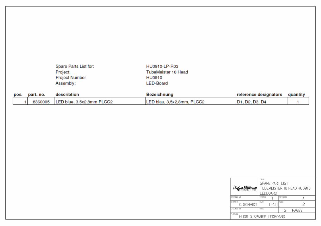
LED-board Rev.: A page: 21 - 22
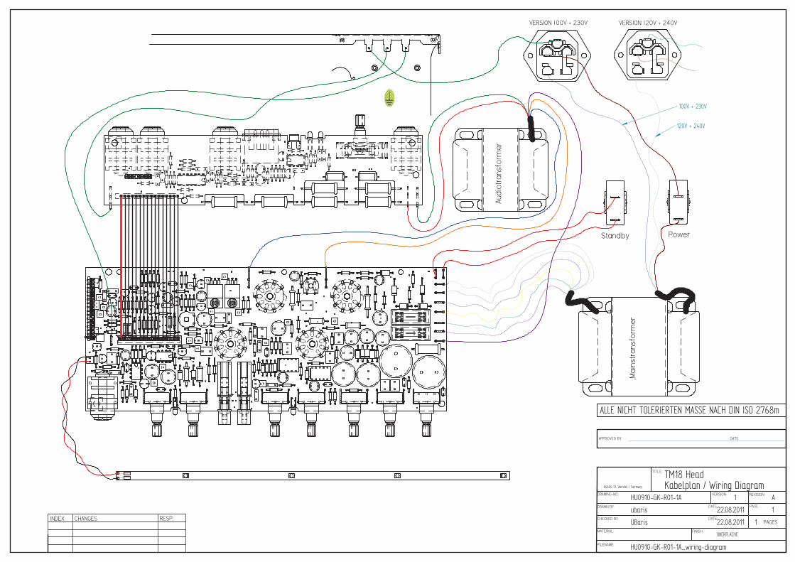
cabling complete Rev.: A page: 23
circuit diagrams mainboard Rev.: G page: 24
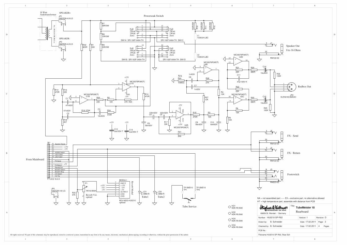
rearboard Rev.: D page: 25
LED-board Rev.: A page: 26
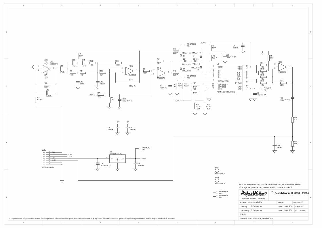
Reverb-board Rev.: E page: 27
tube bias regulator Rev.: A page: 28
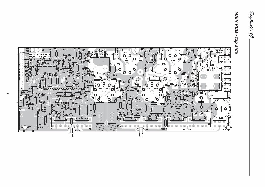
layout diagrams mainboard page: 29 - 30
rearboard / LED-board page: 31
tube bias regulator page: 32
Directory

11
eng
lish
Things to Do Before Operating the Amp
• Please read these instructions carefully, particularly
the notes on safety, before operating the amp.
• The manufacturer disclaims any liability or
responsibility whatsoever for any damage or defect
to this and other devices resulting from misuse.
• Before you plug the TubeMeister 18 into a
mains power outlet, make sure its POWER and
STANDBY switches are off (both pointing down)
and that the voltage rating indicated on the amp’s
rear panel matches your local mains current.
• HEAD only: Please remember to always operate
the amp with a speaker connected. The only
exception to this rule is when the POWER SOAK
is set to the SPEAKER OFF position. Always
ensure the connected cabinet’s impedance is no less
than 8 Ω (see SPEAKER OUT for more on this).
• A word of warning before you fire up your
TubeMeister 18: It’s loud, and high volume levels
can cause hearing damage.
Table of contents
1Connections & Control Features 12
2 Standard Setup/Cable Connections 15
3 Tube Safety Control (TSC) 16
4 Technical Specifications 17
12
1Connections and Control Features
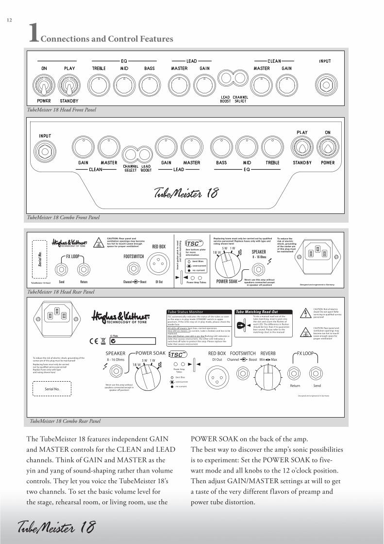
The TubeMeister 18 features independent GAIN
and MASTER controls for the CLEAN and LEAD
channels. Think of GAIN and MASTER as the
yin and yang of sound-shaping rather than volume
controls. They let you voice the TubeMeister 18’s
two channels. To set the basic volume level for
the stage, rehearsal room, or living room, use the
POWER SOAK on the back of the amp.
The best way to discover the amp’s sonic possibilities
is to experiment: Set the POWER SOAK to five-
watt mode and all knobs to the 12 o’clock position.
Then adjust GAIN/MASTER settings at will to get
a taste of the very different flavors of preamp and
power tube distortion.
TubeMeister 18 Head Front Panel
TubeMeister 18 Combo Front Panel
TubeMeister 18 Head Rear Panel
TubeMeister 18 Combo Rear Panel

13
eng
lish
To avoid very loud and unwelcome surprises, make
a habit of backing the VOLUME knob of the guitar
connected to the TubeMeister all the way down
before switching on the amp.
1.1 Front Panel
POWER/ON
Set this switch to ON to get the mains power
flowing. The amp lights up and the tubes will begin
to heat up.
PLAY/STANDBY
Give the tubes about 30 seconds to warm up; then
you can flip the STANDBY switch to PLAY. The
amp is now ready to operate. When taking a short
break from playing, please use the STANDBY switch
so the tubes remain at operating temperature. This
protects them and ensures they last longer.
INPUT
Connect your guitar to this input using a shielded
cord.
CHANNEL SELECT
This switch activates either the CLEAN or LEAD
channel. Its LED lights up blue when you select the
LEAD channel. Connecting a footswitch disables
the front panel button. You can then switch channels
via footswitch only, and the CHANNEL SELECT
light indicates which channel is active.
CLEAN Channel
The CLEAN channel delivers warm tube tone.
Its dynamic range is considerable, sweeping from
pristine clean to throaty crunch sounds. Remarkably
responsive to the various pickup types, it also reacts
to the slightest nudge of the guitar’s volume knob.
GAIN
The GAIN knob determines the CLEAN channel’s
input sensitivity. Depending on the output levels of
the pickups in your instrument, the channel will begin
to overdrive somewhere around the 12 o'clock setting.
This knob does not influence the LEAD channel.
MASTER
This knob adjusts the CLEAN channel’s volume
without affecting the LEAD channel’s volume.
LEAD Channel
The LEAD channel delivers harmonically rich tube
distortion and plenty of gain reserves to go from
edgy overdrive to soaring lead sounds. You can even
clean up its tone by backing off the guitar’s volume
knob. This gives you a huge spectrum of sounds
to play with simply by working the pickup selector
switch and adjusting the volume knob.
GAIN
This knob adjusts the amount of tube distortion.
To discover the amazing range of sounds that this
channel puts at your fingertips, we recommend
that you first set the GAIN knob to the 12 o’clock
position, and then experiment with the guitar’s
volume knob, pickup selector, and the amp’s
BOOST switch.
MASTER
This knob adjusts the LEAD channel’s volume.
Again, first set GAIN to the 12 o’clock position
and experiment. If you wish to conjure creamy
lead tones, turn the knob well up to dial in smooth
power amp saturation. If you’re aiming for an
edgier metal sound, say for heavy riffs, try backing
off the MASTER knob and turning up the GAIN
knob. Usually smooth power amp saturation is less
desirable for this type of metal tone.
NOTE: Be advised that you cannot mute the
TubeMeister 18 by turning the LEAD MASTER knob
all the way down (to the far left position). If you wish
to play at very soft levels, we recommend that you
attenuate the amp’s overall output by selecting either
the five- or one-watt mode (see POWER SOAK)
rather than backing the MASTER volume way down.
LEAD BOOST
This switch re-voices the LEAD channel to summon
modern high-gain sound that pairs plenty of punch
with endless sustain. Its LED lights up red when
14
BOOST is active. Connecting a footswitch disables
the front panel button. You can then switch BOOST
via footswitch only, and the button merely serves to
indicate the function’s status.
BASS, MID, TREBLE
Although the two channels share these common
tone controls, their separate EQ filtering circuits are
voiced differently to achieve optimum results for
each channel.
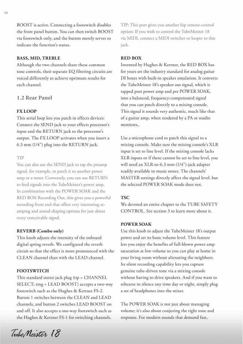
1.2 Rear Panel
FX LOOP
This serial loop lets you patch in effects devices:
Connect the SEND jack to your effects processor's
input and the RETURN jack to the processor’s
output. The FX LOOP activates when you insert a
6.3 mm (1/4”) plug into the RETURN jack.
TIP
You can also use the SEND jack to tap the preamp
signal, for example, to patch it to another power
amp or a tuner. Conversely, you can use RETURN
to feed signals into the TubeMeister’s power amp.
In combination with the POWER SOAK and the
RED BOX Recording Out, this gives you a powerful
recording front end that offers very interesting re-
amping and sound-shaping options for just about
every conceivable signal.
REVERB (Combo only)
This knob adjusts the intensity of the onboard
digital spring reverb. We configured the reverb
circuit so that the effect is more pronounced with the
CLEAN channel than with the LEAD channel.
FOOTSWITCH
This standard stereo jack plug (tip = CHANNEL
SELECT; ring = LEAD BOOST) accepts a two-way
footswitch such as the Hughes & Kettner FS-2.
Button 1 switches between the CLEAN and LEAD
channels, and button 2 switches LEAD BOOST on
and off. It also accepts a one-way footswitch such as
the Hughes & Kettner FS-1 for switching channels.
TIP: This port gives you another hip remote-control
option: If you wish to control the TubeMeister 18
via MIDI, connect a MIDI switcher or looper to this
jack.
RED BOX
Invented by Hughes & Kettner, the RED BOX has
for years set the industry standard for analog guitar
DI boxes with built-in speaker emulation. It converts
the TubeMeister 18’s speaker out signal, which is
tapped post power amp and pre POWER SOAK,
into a balanced, frequency-compensated signal
that you can patch directly to a mixing console.
This signal it sounds very authentic, much like that
of a guitar amp, when rendered by a PA or studio
monitors,.
Use a microphone cord to patch this signal to a
mixing console. Make sure the mixing console’s XLR
input is set to line level. If the mixing console lacks
XLR inputs or if these cannot be set to line level, you
will need an XLR-to-6.3 mm-(1/4”)-jack adapter
readily available in music stores. The channels’
MASTER settings directly affect the signal level, but
the selected POWER SOAK mode does not.
TSC
We devoted an entire chapter to the TUBE SAFETY
CONTROL. See section 3 to learn more about it.
POWER SOAK
Use this knob to adjust the TubeMeister 18’s output
power and set its basic volume level. This feature
lets you enjoy the benefits of full-blown power amp
saturation at low volume so you can play at home in
your living room without alienating the neighbors.
Its silent recording capability lets you capture
genuine tube-driven tone via a mixing console
without having to drive speakers. And if you want to
rehearse in silence any time day or night, simply plug
a set of headphones into the mixer.
The POWER SOAK is not just about managing
volume; it’s also about conjuring the right tone and
response. For modern sounds that demand fast,

15
eng
lish
tightly focused response, set the POWER SOAK to
full power and turn the MASTER knob down. If
you want classic rock sounds replete with spongier
power tube saturation, drop the POWER SOAK
down to a lower setting and crank the MASTER
knob to give those power tubes a workout.
The POWER SOAK offers the following modes:
Normal operation - full power at 18 watts
Power reduction to 5 watts
Power reduction to 1 watt
Mute (Speaker off) = 0 watts
Note that if you choose to mute the amp, you do
not need to connect a speaker to the TubeMeister
18’s SPEAKER output. Designed to enable silent
recording, this option provides the full signal to the
RED BOX output.
SPEAKER
Connect a speaker cabinet designed for guitar amps
to this jack. Using a single speaker cord, you can
connect any cabinet or combination of cabinets
whose total impedance ranges between 8 Ω and 16
Ω. The formula below serves to calculate the overall
impedance (R) of two cabinets (R1, R2).
For cabinets wired in series: R = R1 + R2
Example: If you connect two 8 Ω cabinets, the overall
impedance is 16 Ω. However, very few modern
cabinets are wired in series. Parallel circuits like that of
the TubeMeister 112 cabinet are far more common.
For cabinets wired in parallel:
R = (R1 x R2 ) / (R1 + R2)
Here’s an example with to 16Ω cabs:
R = ( 16 x 16 ) / ( 16 + 16 )
R = 256 / 24
R = 8
HEADS UP: On the Combo version, this jack is
already occupied by the internal speaker. Of course,
you are free to connect another cabinet to the
SPEAKER jack if you wish. To do so, simply unplug
the built-in speaker.
MAINS IN
Connect the factory-included power cord (MAINS
LEAD) to this socket. Ensure the amp's voltage
rating matches your local AC voltage rating before
you plug the cord into the wall socket. The shaft
holding the mains fuses is located next to this
socket. When replacing blown fuses, make sure you
use specified replacement fuses only (see Technical
Specifications).
2 Standard Setup/ Cable Connections
Footswitch
Input
Send Return
Speaker Out
Guitar Cabinet
FX-Unit
RED BOXDI OUT
Stage or Recording Mixer
Rock on Stage Play at Home Record at Night
16
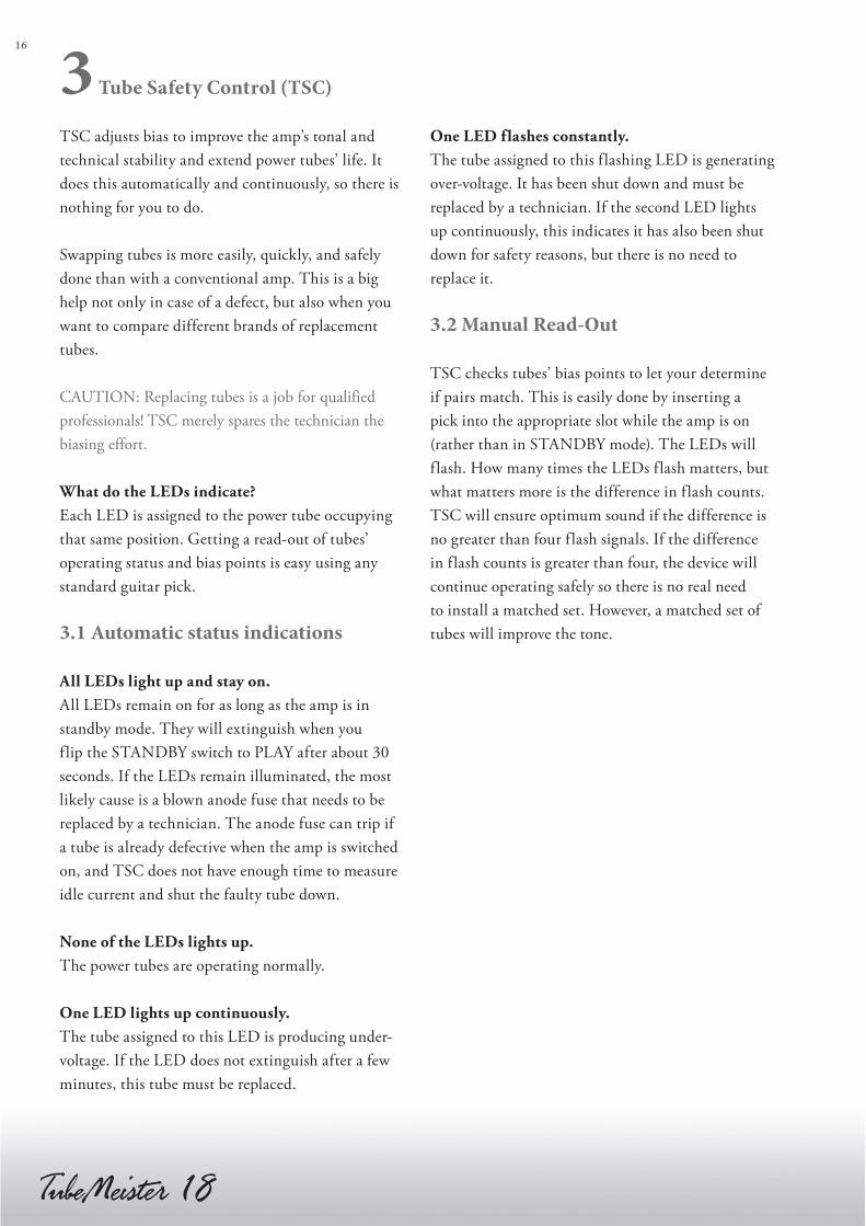
3 Tube Safety Control (TSC)
TSC adjusts bias to improve the amp’s tonal and
technical stability and extend power tubes’ life. It
does this automatically and continuously, so there is
nothing for you to do.
Swapping tubes is more easily, quickly, and safely
done than with a conventional amp. This is a big
help not only in case of a defect, but also when you
want to compare different brands of replacement
tubes.
CAUTION: Replacing tubes is a job for qualified
professionals! TSC merely spares the technician the
biasing effort.
What do the LEDs indicate?
Each LED is assigned to the power tube occupying
that same position. Getting a read-out of tubes’
operating status and bias points is easy using any
standard guitar pick.
3.1 Automatic status indications
All LEDs light up and stay on.
All LEDs remain on for as long as the amp is in
standby mode. They will extinguish when you
flip the STANDBY switch to PLAY after about 30
seconds. If the LEDs remain illuminated, the most
likely cause is a blown anode fuse that needs to be
replaced by a technician. The anode fuse can trip if
a tube is already defective when the amp is switched
on, and TSC does not have enough time to measure
idle current and shut the faulty tube down.
None of the LEDs lights up.
The power tubes are operating normally.
One LED lights up continuously.
The tube assigned to this LED is producing under-
voltage. If the LED does not extinguish after a few
minutes, this tube must be replaced.
One LED flashes constantly.
The tube assigned to this f lashing LED is generating
over-voltage. It has been shut down and must be
replaced by a technician. If the second LED lights
up continuously, this indicates it has also been shut
down for safety reasons, but there is no need to
replace it.
3.2 Manual Read-Out
TSC checks tubes’ bias points to let your determine
if pairs match. This is easily done by inserting a
pick into the appropriate slot while the amp is on
(rather than in STANDBY mode). The LEDs will
f lash. How many times the LEDs flash matters, but
what matters more is the difference in flash counts.
TSC will ensure optimum sound if the difference is
no greater than four flash signals. If the difference
in flash counts is greater than four, the device will
continue operating safely so there is no real need
to install a matched set. However, a matched set of
tubes will improve the tone.
17
eng
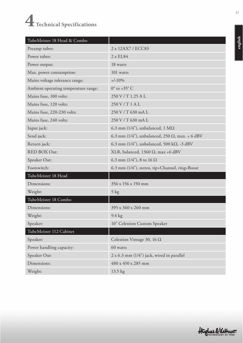
lishTubeMeister 18 Head & Combo
Preamp tubes: 2 x 12AX7 / ECC83
Power tubes: 2 x EL84
Power output: 18 watts
Max. power consumption: 101 watts
Mains voltage tolerance range: +/-10%
Ambient operating temperature range: 0° to +35° C
Mains fuse, 100 volts: 250 V / T 1.25 A L
Mains fuse, 120 volts: 250 V / T 1 A L
Mains fuse, 220-230 volts: 250 V / T 630 mA L
Mains fuse, 240 volts: 250 V / T 630 mA L
Input jack: 6.3 mm (1/4"), unbalanced, 1 MΩ
Send jack: 6.3 mm (1/4"), unbalanced, 250 Ω, max. + 6 dBV
Return jack: 6.3 mm (1/4"), unbalanced, 500 kΩ, -3 dBV
RED BOX Out: XLR, balanced, 1360 Ω, max +6 dBV
Speaker Out: 6.3 mm (1/4"), 8 to 16 Ω
Footswitch: 6.3 mm (1/4"), stereo, tip=Channel, ring=Boost
TubeMeister 18 Head
Dimensions: 356 x 156 x 150 mm
Weight: 5 kg
TubeMeister 18 Combo
Dimensions: 395 x 360 x 260 mm
Weight: 9.4 kg
Speaker: 10" Celestion Custom Speaker
TubeMeister 112 Cabinet
Speaker: Celestion Vintage 30, 16 Ω
Power handling capacity: 60 watts
Speaker Out: 2 x 6.3 mm (1/4") jack, wired in parallel
Dimensions: 480 x 450 x 285 mm
Weight: 13.5 kg
4 Technical Specifications
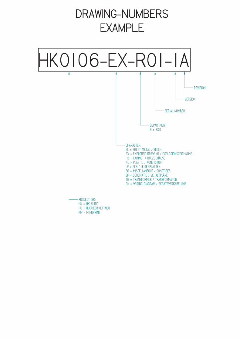
DRAWING-NUMBERSEXAMPLE
HK0106-EX-R01-1A
PROJECT-NR.:HK = HK AUDIOHU = HUGHES&KETTNERMP = MINDPRINT
CHARACTER:BL = SHEET METAL / BLECHEX = EXPLODED DRAWING / EXPLOSIONSZEICHNUNGHZ = CABINET / HOLZGEHÄUSEKU = PLASTIC / KUNSTSTOFFLP = PCB / LEITERPLATTENSO = MISCELLANEOUS / SONSTIGESSP = SCHEMATIC / SCHALTPLÄNETR = TRANSFORMER / TRANSFORMATORGK = WIRING DIAGRAM / GERÄTEVERKABELUNG
DEPARTMENT:R = R&D
SERIAL NUMBER
VERSION
REVISION

Stand
Standard for single wire confection.
16 B 150 638 I - 485 W Z I 1015
style 1015 according UL specifications
I = completely insulated with black shrinktube or appropriate sleeve
IT = partly insulated; only crimp connection insulated.
no marking = without insulation
Z = with additional junction
no marking = without additional junction
W = angled faston
no marking = straight faston
Faston connector brass tin-plated DIN 46245
638 = 6,3 * 0,8 [mm]
488 = 4,8 * 0,8 [mm]
485 = 4,8 * 0,5 [mm] if fully insulated (I) insulation with blue shrinktube
if partly insulated (IT) use IF 602 485 .
288 = 2,8 * 0,8 [mm]
285 = 2,8 * 0,5 [mm] if fully insulated (I) insulation with blue shrinktube
if partly insulated (IT) use IF 602 485
abiso = 5mm bared and tin-plated (teilabzug)
text for special constructions, (for example. 4mm ringshaped faston)
the larger faston connector always mentioned at first. (Nathan drawing number controlling)
lenght in mm within a 50 mm raster
colour
B = black (phase conductor)
R = red
BR = brown
BL = blue (neutral conductor)
W = white
YG = yellow-green (ground bonding/ earthing connection)
cross section
16 = AWG 16 (prefered usage)
Q1.5 = H07VK 1,5mm² (prefered usage)
wire designation:
P + lfd Nr. = AWG single wire black, red, blue, brown or white
E + lfd Nr. = AWG single wire green- yellow
L + lfd Nr. = twisted AWG double wire, lenght specification always in twisted condition
FQL + lfd Nr. = crossover wiring H07VK
17. Jun 04
Regarding special wirings like wiring harness or similar, drawings will be prepared and appropriate
drawing numbers will be stored in the article archive.

Service Documents
Confidential, for authorized service technicians only!
Do not disclose this information to or share these documents with third parties.
TECHNICAL SERVICE:
Stamer Musikanlagen GmbH • Magdeburger Str. 8 • 66606 St.Wendel • Germany
Music & Sales P.E. GmbH • Leipziger Str. 3 • 66606 St.Wendel • Germany
HU0910TubemeisterTM 18 Head


66606 St. Wendel / Germany
HU0910-EX-R01-1B-COMPLETE
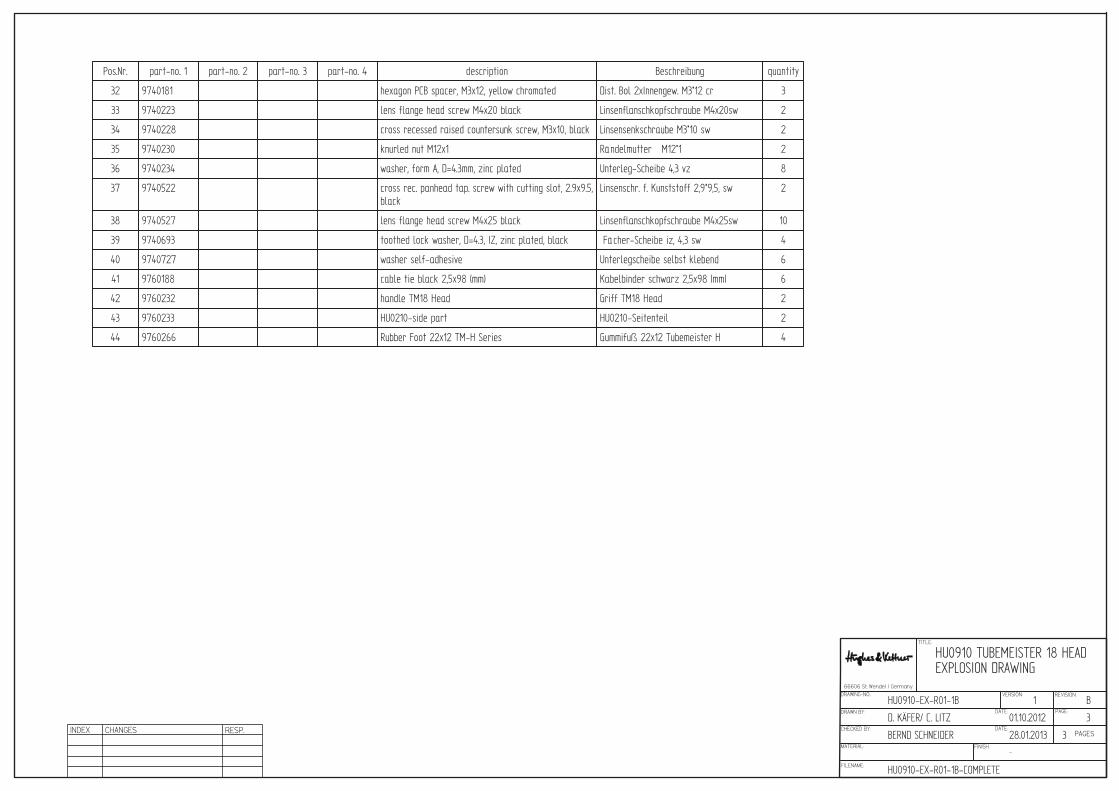
HU0910 TUBEMEISTER 18 HEADEXPLOSION DRAWING
HU0910-EX-R01-1B
D. KÄFER/ C. LITZ 3
3
01.10.2012
B1
BERND SCHNEIDER 28.01.2013
-
TITLE:
DRAWN BY: PAGE:DATE:
DRAWING-NO.: VERSION: REVISION:
CHECKED BY: DATE:
MATERIAL: FINISH:
FILENAME:
PAGESINDEX CHANGES RESP.
Pos.Nr. part-no. 1 part-no. 2 part-no. 3 part-no. 4 description Beschreibung quantity
32 9740181 hexagon PCB spacer, M3x12, yellow chromated Dist. Bol 2xInnengew. M3*12 cr 3
33 9740223 lens flange head screw M4x20 black Linsenflanschkopfschraube M4x20sw 2
34 9740228 cross recessed raised countersunk screw, M3x10, black Linsensenkschraube M3*10 sw 2
35 9740230 knurled nut M12x1 Rändelmutter M12*1 2
36 9740234 washer, form A, D=4.3mm, zinc plated Unterleg-Scheibe 4,3 vz 8
37 9740522 cross rec. panhead tap. screw with cutting slot, 2.9x9.5,black
Linsenschr. f. Kunststoff 2,9*9,5, sw 2
38 9740527 lens flange head screw M4x25 black Linsenflanschkopfschraube M4x25sw 10
39 9740693 toothed lock washer, D=4.3, IZ, zinc plated, black Fächer-Scheibe iz, 4,3 sw 4
40 9740727 washer self-adhesive Unterlegscheibe selbst klebend 6
41 9760188 cable tie black 2,5x98 (mm) Kabelbinder schwarz 2,5x98 (mm) 6
42 9760232 handle TM18 Head Griff TM18 Head 2
43 9760233 HU0210-side part HU0210-Seitenteil 2
44 9760266 Rubber Foot 22x12 TM-H Series Gummifuß 22x12 Tubemeister H 4

TITLE:
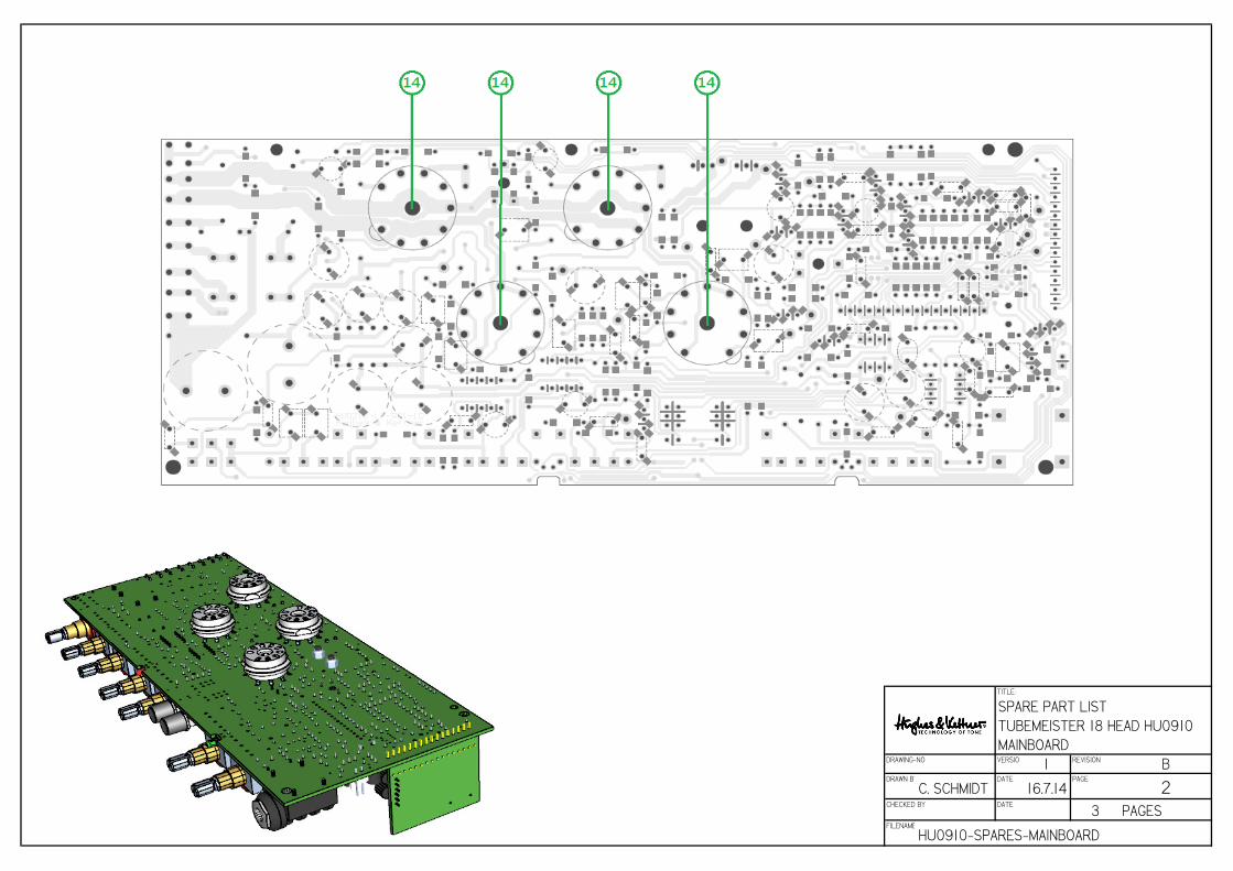
SPARE PART LIST
TUBEMEISTER 18 HEAD HU0910
MAINBOARDDRAWING-NO VERSION 1 REVISION BDRAWN BY:
C. SCHMIDTDATE
16.7.14PAGE
1CHECKED BY DATE
3 PAGESFILENAME
HU0910-SPARES-MAINBOARD
TITLE:
SPARE PART LIST
TUBEMEISTER 18 HEAD HU0910
MAINBOARDDRAWING-NO VERSION 1 REVISION BDRAWN BY:
C. SCHMIDTDATE
16.7.14PAGE
2CHECKED BY DATE
3 PAGESFILENAME
HU0910-SPARES-MAINBOARD

TITLE:
SPARE PART LIST
TUBEMEISTER 18 HEAD HU0910
MAINBOARDDRAWING-NO VERSION 1 REVISION BDRAWN BY:
C. SCHMIDTDATE
16.7.14PAGE
3CHECKED BY DATE
3 PAGESFILENAME
HU0910-SPARES-MAINBOARD
TITLE:
DRAWN BY: PAGE:DATE:
DRAWING-NO.: VERSION: REVISION:
CHECKED BY: DATE:
MATERIAL: FINISH:
FILENAME:
PAGES
HU0910-GK-R01-1A_wiring-diagram
TM18 HeadKabelplan / Wiring Diagram
HU0910-GK-R01-1A
ubaris 1
1
22.08.2011
A1
UBaris 22.08.2011
OBERFLÄCHE
INDEX CHANGES RESP.
APPROVED BY: DATE:
ALLE NICHT TOLERIERTEN MASSE NACH DIN ISO 2768m
66606 St. Wendel / Germany
Audi
otra
nsfo
rmer
;Mai
nstr
ansf
orm
er
100V + 230V
120V + 240V
VERSION 100V + 230V VERSION 120V + 240V
PowerStandby

1 2 3 4 5 6 7 8
A
B
C
D
87654321
D
C
B
A
All rights reserved. No part of this schematic may be reproduced, stored in a retrieval system, transmitted in any form or by any means, electronic, mechanical, photocopying, recording or otherwise, without the prior permission of the author. Filename:HU0210-SP-R01_Main.Sch
PCB No.:
Page:
Pages
1
4Checked by:
Drawn by: Date:
Date:
B. Schneider
B. Schneider
13.04.2011
13.04.2011
Number: Version: Revision:1HU0210-SP-R01 G
66606 St. Wendel / Germany
Title:TubeMeister 18
NA = not assembled part ----- EX = exclusive part, no alternative allowed
HT = high temperature part, assemble with distance from PCB
Mainboard
S
TST
SS
J1
RM122-02
+3
-2
1
84
VC
CV
EE
U1A
MC33078P(MOT)
+5
-6
7U1B
MC33078P(MOT)
R5
1K0
C3
10n/63V
C410n/63V
D3
BZX55V_3V9
D4
BZX55V_3V9
D5
BZX55V_3V9
D6
BZX55V_3V9
R13
10K
C11330p/100V-K
C9470n/63V
R553K3
R8
220R
C8
4u7/63VR32K2 C1
1u/63V
+15V
-15V
D2
BZ
X7
9C
_2
V7
D1
BZ
X7
9C
_2
V7
R101MEG
Q1
BF245B
R3047K
R18470K
Q2BF245B
R147K
C12
1n/63V
R28
47K
1
2
3
T1AECC83S-CZ-N-PCB
1
2
3
T2A
EC
C8
3S
-CZ
-N-P
CB
954
T1
CE
CC
83
S-C
Z-N
-PC
B
R38100K/1W
R40100K/1W
R64100K
R61K0
R612K7
R22470K
R41
220K
R7433K
R111MEG
R42220K
R3
91
00
K/1
W
C14
22n/400V
C15
22n/400V
C23100p/100V-K
C22
47p/100V-K
R801K5
C25
220p/500V-K
C24
470p/500V-K
C16
22n/400V
C1722n/400V
R2947K
6
7
8
T1B
EC
C8
3S
-CZ
-N-P
CB
Q3BF245B
C13
47
n/6
3V
C21u/63V
+350V
+350V
+350V
C2
11
n/4
00
V
LR
P5
RK16-A1MEG
LR
P6
RK16-B25K
LR
P2
RK
16
-B5
00
K
LR
P4
RK16-B500K
R19470K
R48270K
R20470K
C2
66
80
p/1
00
V-K
1
9
2
10
3
11
4
12
5
13
6
14
7
15
8
16JP1
TJC3-16P
+3
-2
1
84
VC
CV
EE
U2A
MC33078P(MOT)
+5
-6
7U2B
MC33078P(MOT)
R81 820K
R43220K
Q5BF245B
+15V
-15V
CH-Switch
CH-Tip
BOOST-Ring
BOOST-Switch
FX-Send
FX-Return
A-BIAS-Switch
LED-Tube1
LED-Tube2
R9
220R
-15V+15V
D7
1N
40
07
G
D81N4007G
D10
1N
40
07
G
D91N4007G
C3
16
8U
/45
0V
R49150K/1W
R50150K/1W
C3
26
8U
/45
0V
R51
470R/5W R53
4K7/2W
R54
15K/2W
C3
54
u7
/45
0V
C3
64
u7
/45
0V
C3
74
u7
/45
0V
+350V+370V+380V+390V
D11
1N4007G
D121N4007G
C292200u/25V
C302200u/25V
C331000u/16V
C341000u/16V
D16BZX85C_15V
D1
7
BZ
X8
5C
_1
5V
+15V
-15V
C42
220u/63V
C43220u/63V
D131N4007G
D14
1N4007G-63V
+22V
R83220R/1W
C4
44
7u
/10
0V
C4
54
7u
/10
0V
-59V
954
T2
CE
CC
83
S-C
Z-N
-PC
B
7
2
3
9
6
T3A
EL
84
M-R
S-N
-PC
B-S
7
2
3
9
6
T4AEL84M-RS-N-PCB-S
45
T3
B
EL
84
M-R
S-N
-PC
B-S
45
T4
B
EL
84
M-R
S-N
-PC
B-S
R8
5
10
0R
/1W
R8
6
10
0R
/1W
OUT TUBE-21
OUT TUBE-12
OFF TUBE-13
OFF TUBE-24
Service5
LED-T26
OUT +5V8
GND9
GND10
SIGNAL11
IN - REF13
IN +TUBE-212
IN +TUBE-114
VCC16
LED-T17
Powerfail15
MODUL1BIAS-MOD-ECO_RD0710
6
7
8
T2B EC
C8
3S
-CZ
-N-P
CB
R8756K/1W
R7
1K0
R8856K/1W
Reverb1
Reverb2
R15
10K
R5722K
R56
68K
R1410K
R21470K L
R
PT1PT10LV-100K
Q6
BC546B
Q9BC556B
C3822u/63V
C10
470n/63V
R3147K
-59V
+370V
R121MEG
C18
22n/400V
C19
22n/400VR45220K
R44
220K
C4
12
2u
/63
V
C4
02
2u
/63
V
Q14STP10NK60ZFP
Q15STP10NK60ZFP
Q7
BC546B
R58
22K
-63V
R921K0/2W
R9
31
K0
/2W
+380V
R3747K
C52
2u2/63V
R901K5/1W
D15
1N4007G
+390V
Anode1
Anode2
Audiotransformer18 Watt
No
.: HU
02
10
-TR
-R0
2-x
x
Q4BF245B
+5V
+5V
D23BZX55V_8V2
+22V
D2
0
1N
41
48
D2
1
1N
41
48
C7
10
n/6
3V
C6
10
n/6
3V
LD2
3MM-R
LD
1
3M
M-G
+22V
+22V
Q8
BC546B
Q11
BC
55
6B
Q1
0B
C5
56
B
D19 1N
41
48
D18 1N
41
48
R68100K
R69100K
R6
61
00
K
R7
01
00
K
R72
100K
R47
220K
R4
62
20
K
R42K2
Q1
2B
C5
56
B R3547K
R3
4
47
K
R71100K
-15V
+15V
D221N4148
R2
7
4M
EG
7
Fet-Mute
R67
100K-15V
Fet-C
H-S
W
Fet-CH-Boost-SW
Cle
an
Lead
Boost
TO
RE
AR
BO
RD
TS
C S
YS
TE
M
Boost SwitchChannel Switch
R24
4MEG7
R234MEG7
R25
4MEG7
R26
4MEG7
R9615K
C5310u/63V
+22V
R6
51
00
K
R5922K
Fet-C
H-S
W-N
eg
FU
1
T2
00
mA
FU
2
T3
15
mA
JP6
FA
ST
ON
-4.8
-ST
JP5FASTON-4.8-ST
6,3
VA
C1
7V
AC
28
0V
AC
MainsSwitch
StandbySwitch
Mains Connector
240V = T0,63A
120V = T1A
100V = T1,25A
220 - 230V = T0,63A
MAINS
240VAC
230VAC
0VAC
or 120VAC
or 100VAC
Mains Transformer
No.: HU0210-TR-R01-xx
INPUT
-22V
-22V
Lig
ht
Pow
er
L1
R1
P7A
RK
16
-A5
00
K-S
T
L2
R2
P7B
RK
16
-A5
00
K-S
T
LR
P1
RK
16
-A1
ME
G
LR
P3
RK
16
-A2
50
K
PWM-T1
PWM-T2
Powerfail
IN-T1
IN-T2
Signal
OFF-Switch
Speaker-Signal
C5
10
n/6
3V
JP8FASTON-4.8-ST
R7
93
K9
JP10FASTON-4.8-ST
JP12FASTON-4.8-ST
JP11FASTON-4.8-ST
JP13FASTON-4.8-ST
JP14FASTON-4.8-ST
JP15FASTON-4.8-ST
Reverb-Out
+
C5
52
u2
/35
V-T
+C5
42
u2
/35
V-T
+15V -15V
LR P
T2
PT
10
LV
-25
0R
NA
JP4
FASTON-4.8-LG
JP3
FASTON-4.8-LG
HO1NDK-R0-B32HO2NDK-R0-B32HO3NDK-R0-B32HO4NDK-R0-B40HO5NDK-R0-B40HO6NDK-R0-B40
12 3
SW1AWPML2-S-B
SW1CWPML2-S-B
45 6
SW1B
WPML2-S-B
1
10
+
-
REL2AFRT5-1-12V
1
10
+
-
REL1AFRT5-1-12V
8
9
7REL1C
FRT5-1-12V
3
2
4REL1B
FRT5-1-12V
3
2
4
REL2B
FRT5-1-12V
R94
220R
D24
BZX55V_8V2
TP1TP-THT30
TP2TP-THT30
TP3TP-THT30
TP4TP-THT30
TP7TP-THT30
TP5
TP-THT30
TP10TP-THT30
TP9
TP-THT30
TP16
TP-THT30
R89
1R5/1W
R91
1R5/1W
TP13TP-THT30
TP12TP-THT30
TP11TP-THT30
TP14TP-THT30
TP15TP-THT30
TP8TP-THT30
TP6TP-THT30
HO7NDK-R0-B30
8
9
7REL2C
FRT5-1-12V
HO8NDK-R0-B30
12
JP7MTA100-02P
R52
100R/2W
R82
150R/2W
R6268K
R63150K
C46100n/250V
C56100n/63V-K
C4
91
00
n/6
3V
-K
C2
72
n2
/63
V-K
C2
82
n2
/63
V-K
Q13
BC
54
6B
C48
68n/63V
C4
7
68
n/6
3V
C501u0/63V
C511u0/63V
R7
83
3K
R7
53
3K
R7
61
0K
R7
71
0K
R3239K
R3339K
R841K0/1W
NA
C391u/63V
R2680R/1W
12 3
SW2AWPML2-S-R
45 6SW2B
WPML2-S-R
SW2C
WPML2-S-R
R95
470R
R604K7
R162K2
R73
24KR98
100KR97
22K
R1
74
70
KR
36
22
K
JP2FASTON-4.8-ST
C20
3n9/400V
Lead Gain
Clean Gain
Treble
Treble
Bass
MID
Lead Master
Clean
Master
Lead
130°C
1 2 3 4 5 6 7 8
A
B
C
D
87654321
D
C
B
A
All rights reserved. No part of this schematic may be reproduced, stored in a retrieval system, transmitted in any form or by any means, electronic, mechanical, photocopying, recording or otherwise, without the prior permission of the author. Filename:HU0210-SP-R02_Rear.Sch
PCB No.:
Page:
Pages
2
4Checked by:
Drawn by: Date:
Date:
B. Schneider
B. Schneider
17.02.2011
17.02.2011
Number: Version: Revision:1HU0210-SP-R02 D
66606 St. Wendel / Germany
Title:TubeMeister 18
NA = not assembled part ----- EX = exclusive part, no alternative allowed
HT = high temperature part, assemble with distance from PCB
Rearboard
S
TST
SS
J1
RM122-02
S
TST
SS
J5
RM122-02
S
TST
SS
J4
RM122-02
LD23MM-R
LD13MM-R
+3
-2
1
84
VCC
VEE
U1AMC33078P(MOT)
+5
-6
7
U1BMC33078P(MOT)
+3
-2
1
41
1
VC
CV
EE
U2A
MC33079P(MOT)
+5
-6
7
U2BMC33079P(MOT)
+10
-9
8U2C
MC33079P(MOT)
+12
-13
14
U2DMC33079P(MOT)
12345678910111213141516
W1
F-TJC3-16-2.5
TP1TP-SMD10
TP2TP-SMD10
R1
1
10
0R
/5W
R1
0
10
0R
/5W
R1
2
10
0R
/5W
R933R/5W
L21000UH-LBC
L11000UH-LBC
SPEAKER+
SPEAKER-
Full5Watt1WattZero
Full5Watt1WattZero
Full5Watt1WattZero
Full5Watt1WattZero
Powersoak Switch
1324
JP2XLR/M-NC3MAAH-15V
+15V
R13470R
R1633K
R184K7
R19 270K
R20
22K
R2
10K R2347K
C2
47n/63V
C1
47n/63V
C3
10n/63V
C956n/63V
C4100n/63V
C5100n/63V
C856n/63V
C106n8/63V
C6
1n/63V
C7
1n/63V
R15
470R
R1733K
R31
5K6
R14470R
R510K
R6
10K
R2712K
R24
10MEG
R28
27K
R3
10K
R410K
C11
47p/100V-K
R22
22K
R21
22K
NA
R
S
TST
RS
SS
J3
RM223-02
+15V-15V
Speaker Out
8 to 16 Ohms
Redbox Out
FX - Send
FX - Return
Footswitch
Tube Service
Tube1 Tube2
From Mainboard
CH-Switch
CH-Tip
BOOST-Ring
BOOST-Switch
FX-Send
FX-Return
A-BIAS-Switch
LED-Tube1
LED-Tube2
R32820R
Audiotransformer18 Watt
No
.: HU
02
10
-TR
-R0
2-x
x
Speaker-Signal
+5V
LR
P1
RK16-B50K+5V
-15V+15V
Reverb Vol.optinal
optinal
Rev
erb M
odul
Reverb-Out
+15V
-15V
+ C122u2/35V-T +
C132u2/35V-T
+15V -15V
R3347K
JP1FASTON-4.8-LG
JP3FASTON-4.8-LG
C15
10u/63V
C14
10u/63V R26100K
R25100K
R30
680R
R29
680R
HO3NDK-R0-B40
HO2NDK-R0-B40
HO1NDK-R0-B40
HO4NDK-R0-B40
R34
470R
R815R/5W
R739R/5W
JP5FASTON-4.8-LG
12
345
SW1A SR1102F-0404-TH
67
8910
SW1B SR1102F-0404-TH
1112
131415
SW1CSR1102F-0404-TH
1617
181920
SW1DSR1102F-0404-TH
GND1
GND2
OUTPUT3
+ 5V4
- 15V5
+ 15V6
INPUT7
MODUL1
REV-MOD-HU0210
R133K

1 2 3 4 5 6 7 8
A
B
C
D
87654321
D
C
B
A
All rights reserved. No part of this schematic may be reproduced, stored in a retrieval system, transmitted in any form or by any means, electronic, mechanical, photocopying, recording or otherwise, without the prior permission of the author. Filename:HU0210-SP-R03_LED-Board.Sch
PCB No.:
Page:
Pages
3
4Checked by:
Drawn by: Date:
Date:
B. Schneider
B. Schneider
24.09.2010
24.09.2010
Number: Version: Revision:1HU0210-SP-R03 A
66606 St. Wendel / Germany
Title:PortaValve18
NA = not assembled part ----- EX = exclusive part, no alternative allowed
HT = high temperature part, assemble with distance from PCB
LED Board
D1
ZM2CB45S-BLUE
D2
ZM2CB45S-BLUE
D3
ZM2CB45S-BLUE
D4
ZM2CB45S-BLUE
TP1TP-SMD10
TP2TP-SMD10
HO1
NDK-R0-B15
HO2
NDK-R0-B15
1 2 3 4 5 6 7 8
A
B
C
D
87654321
D
C
B
A
All rights reserved. No part of this schematic may be reproduced, stored in a retrieval system, transmitted in any form or by any means, electronic, mechanical, photocopying, recording or otherwise, without the prior permission of the author. Filename:HU0210-SP-R04_RevModu.Sch
PCB No.:
Page:
Pages
4
4Checked by:
Drawn by: Date:
Date:
B. Schneider
B. Schneider
24.08.2011
24.08.2011
Number: Version: Revision:1HU0210-SP-R04 E
66606 St. Wendel / Germany
Title:Reverb Modul HU0210-LP-R04
NA = not assembled part ----- EX = exclusive part, no alternative allowed
HT = high temperature part, assemble with distance from PCB
+3
-2
1
41
1V
CC
VE
E
U1AMC33079
+5
-6
7
U1B
MC33079 +10
-9
8
U1C
MC33079
+12
-13
14
U1D
MC33079
C11
47n-K+
C12
10n-K+
C14
4n7-K+
C1333n-K+
C15820p-K+
R5
10K*
R6
10K*
R139K*
R22
15K*
R23
4K7*
R26
100K*
R7
10K* R810K*
R2
10K*
R9
10K*R18
220R*
R17
220R*
+3,3V
D1
PMLL4148
D5PMLL4148
D2
PMLL4148
D3
PMLL4148
D4
PMLL4148
D6PMLL4148
R11
10K*R12
10K*R13
10K*R14
10K*
+15V
-15V
REV TYPE 111
VDD28
REV TYPE 010
RESET1
IN +2
IN -5
IN +4
IN -3
DECAY TIME6
OUT -23
OUT +25
OUT +24
BYPASS20
GND27
GND19
GND8
VDD13
OUT -26
U2
NEM-FX-SC-REV-SMD
R310K*
R19150R*
C4100n-K+
+3,3V
R24
4K7*R25
4K7*
+3,3V
R28100R*
R29100R*
R27100R*
R1010K*C5
100n-K+
NA NA
NA
1234567
JP1
SL-07P07X1W
+3,3V
C9100n-K+
+15V-15V
Input
Output
+5V
C7100n-K+
C8100n-K+
+15V -15V
C162,2uF/6V-TA
C32,2uF/6V-TA
TP1TP-SMD10
TP2TP-SMD10
TP4TP-SMD10
TP5TP-SMD10
TP3TP-SMD10
TP6TP-SMD10
C17
220p-K+
R21100K*
R15
22K*
R422K*
C62,2uF/6V-TA
IN2
GN
D1
OUT3
U3AP7333-33SAG
HO2
NDK-R0-B15
HO1
NDK-R0-B15
R30
100K*
NA
C10
150p-K+
C1810n-K+
R202K2*
R16100K*
C110uF/4V-TA
C210uF/4V-TA
1 2 3 4 5 6 7 8
A
B
C
D
87654321
D
C
B
A
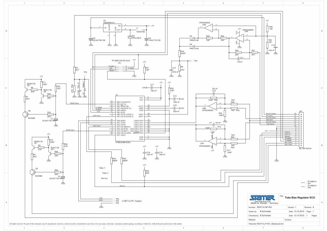
All rights reserved. No part of this schematic may be reproduced, stored in a retrieval system, transmitted in any form or by any means, electronic, mechanical, photocopying, recording or otherwise, without the prior permission of the author. Filename:RD0710-LP-R01_Mainboard.Sch
Material: Surface:
Page:
Pages
1
1Checked by:
Drawn by: Date:
Date:
B.Schneider
B.Schneider
13.10.2010
13.10.2010
Number: Version: Revision:1RD0710-SP-R01 A
66606 St. Wendel / Germany
Title:Tube Bias Regulator ECO
+5V+5V
+5V
GND
GND
GND
T1-MOSI
T2-MISO
CLK
C16
220n-K-
C14
100n-K*
R5110K*
R5210R*
Q11BC817-25
Q7BC807-25
Q2
BC556B
R381K0*
R28
22K*
R29
22K*
R9
47K*
R13100K*
GND
GND
+5V
R421K0*
R431K0*
R22100K*
R20100K*
C1022n-K*
GND
GND
R351K0*
R17100K*
R15100K*
C7 22n-K*
GND
Power-Voltage
Amp-Signal
GND
GND
C522,0uF/50V-S6
GND GND GND
D2PRLL5819
GND
C6100uF/10V-S6
GND
+5V
D3
PMLL4148
R8
47K*C15
470n-K-
GND GND
UART for PC-Adapter
Tube 2
Tube 3
Shunt-Ref.
Bias-IN-Tube1
Bias-IN-Tube2
GND
RESET
TP5TP2
Q9BC817-25
Q5BC807-25
Q3
BC556B
R321K0*
R23
22K*
R24
22K*
R6
47K*
R11100K*
GND
GND
+5V
PWM-Tube1
PWM-Tube2
Bias-Tube1
Bias-Tube2
C122,0uF/10V-S4
C322,0uF/10V-S4
LED-Tube1
LED-Tube2
RXD
TXD
C13
100n-K
*
GND
+3
-2
1
84
VC
CV
EE
U4AOPA2348AID
+5
-6
7U4B
OPA2348AID
+5V
GND
C11
1n5-K*
R4810K*
R4910K*
C12
100n-K*
GND GND
+5V
R25
22K*
GND
+5V
R46
10K*
R45
10K*
R44220R*
D4
PMLL4148
IN7
ON
/OF
F5
OUT8
GN
D6
FB4
U5LM2594M-5.0
R47
4K7*
+5V
C17
100n-K*
GND
C18100n-K*
C19100n-K*
GND GND
+5V +5V
TP7TP-SMD10
TP8TP-SMD10
R54680R*
R55680R*
R43K3*
R13K3*
R592K2*
+5V
Service
T1-MOSI
T2-MISO
Service
D5
ZM
M4.7
GND
R34K7*
R50
47K
*
(RESET) PC629
PD0 (RXD)30
PD1 (TXD)31
PD2 (INT0)32
PD3 (OC2B/INT1)1
PD4 (XCK/T0)2
VCC4
GND5
PB6 (XTAL1/TOSC1)7
PB7 (XTAL2/TOSC2)8
PD5 (OC0B/T1)9
PD6 (OC0A/AIN0)10
PD7 (AIN1)11
PB0 (CLKO/ICP1)12
PB1 (OC1A)13
PB2 (SS/OC1B)14
PB3 (MOSI/OC2A)15
PB4 (MISO)16
PB5 (SCK)17
AVCC18
AREF20
GND21
(ADC0) PC023
(ADC1) PC124
(ADC2) PC225
(ADC3) PC326
(ADC4/SDA) PC427
(ADC5/SCL) PC528
GND3
VCC6
ADC619
ADC722
U1
ATMEGA88-20AU
TP3
TP4
R341K0*
135
246
TP1
TP-SMD-2X3-R2.54-B
CLK
T2-MISO
T1-MOSI
+5V
123456789
10111213141516
JP1
SL-16P16X1W
LED-T2
LED-T1
Service
Powerfail
TP6
+5
-6
7
U3BOPA2348AID
+3
-2
1
84
VC
CV
EE
U3A
OPA2348AID
L1
150UH-BC
4
MA
IN P
CB
- top
sid
e

5
MA
IN P
CB
- bo
ttom
sid
e

6
RE
AR
PC
B
Top s
ide
Botto
m s
ide
LE
D P
CB

3
PC
B L
AY
OU
T
AU
TO
PC
B
Top s
ide
Botto
m s
ide