
with polarized and unpolarized controlled beams · with polarized and unpolarized controlled beams...
12
arXiv:0810.2684v1 [astro-ph] 15 Oct 2008 A versatile facility for the calibration of X-ray polarimeters with polarized and unpolarized controlled beams Fabio Muleri a,b , Paolo Soffitta a , Ronaldo Bellazzini c , Alessandro Brez c , Enrico Costa a , Massimo Frutti a , Marcello Mastropietro a,d , Ennio Morelli a,e , Michele Pinchera c , Alda Rubini a , Gloria Spandre c a Istituto di Astrofisica Spaziale e Fisica Cosmica, Via del Fosso del Cavaliere 100, I-00133 Roma, Italy; b Universit`a di Roma Tor Vergata, Dipartimento di Fisica, via della Ricerca Scientifica 1, 00133 Roma, Italy c Istituto Nazionale di Fisica Nucleare, Largo B. Pontecorvo 3, I-56127 Pisa, Italy d CNR, Istituto Metodologie Inorganiche e dei Plasmi, Area Ricerca Montelibretti, Italy e Istituto di Astrofisica Spaziale e Fisica Cosmica, Via Gobetti 101, I-40129 Bologna, Italy ABSTRACT We devised and built a versatile facility for the calibration of the next generation X-ray polarimeters with unpolarized and polarized radiation. The former is produced at 5.9 keV by means of a Fe 55 radioactive source or by X-ray tubes, while the latter is obtained by Bragg diffraction at nearly 45 degrees. Crystals tuned with the emission lines of X-ray tubes with molybdenum, rhodium, calcium and titanium anodes are employed for the efficient production of highly polarized photons at 2.29, 2.69, 3.69 and 4.51 keV respectively. Moreover the continuum emission is exploited for the production of polarized photons at 1.65 keV and 2.04 keV and at energies corresponding to the higher orders of diffraction. The photons are collimated by means of interchangeable capillary plates and diaphragms, allowing a trade-off between collimation and high fluxes. The direction of the beam is accurately arranged by means of high precision motorized stages, controlled via computer so that long and automatic measurements can be done. Selecting the direction of polarization and the incidence point we can map the response of imaging devices to both polarized and unpolarized radiation. Changing the inclination of the beam we can study the systematic effects due to the focusing of grazing incidence optics and the feasibility of instruments with large field of view. Keywords: X-ray polarimetry, Bragg diffraction, calibration 1. INTRODUCTION The continuous development of new polarimeters based on the photoelectric effects has recently renewed the interest in the study of polarization from astrophysical sources in the X-ray band. The Gas Pixel Detector, developed by the INFN of Pisa, 1–3 is one of the most advanced project in this field. It allows a large increase of sensibility with respect to the previous instruments, based on Bragg diffraction or Thomson scattering, and makes feasible the development of the X-ray polarimetry of astrophysical sources, for the first time after the pioneer experiments in the ’70. The current version of the GPD works between 2 and 10 keV, with a sensitivity peaking at about 3 keV. Its response has been studied by employing a Monte Carlo software, while its calibration was at first attained with a polarized source based on Thomson scattering at nearly 90 degrees on a lithium target, enclosed in beryllium to prevent its oxidation and nitridation. However, such a Thomson scattering source doesn’t allow the production of photons below about 5 keV, i.e. in the range of maximum sensitivity of the GPD, because of the photoelectric absorption in the target. Further author information: (Send correspondence to Fabio Muleri) Fabio Muleri: E-mail: [email protected], Telephone: +39-0649934565
Transcript of with polarized and unpolarized controlled beams · with polarized and unpolarized controlled beams...
arX
iv:0
810.
2684
v1 [
astr
o-ph
] 1
5 O
ct 2
008
A versatile facility for the calibration of X-ray polarimeters
with polarized and unpolarized controlled beams
Fabio Muleria,b, Paolo Soffittaa, Ronaldo Bellazzinic, Alessandro Brezc, Enrico Costaa,
Massimo Fruttia, Marcello Mastropietroa,d, Ennio Morellia,e, Michele Pincherac, Alda Rubinia,
Gloria Spandrec
a Istituto di Astrofisica Spaziale e Fisica Cosmica, Via del Fosso del Cavaliere 100, I-00133
Roma, Italy;b Universita di Roma Tor Vergata, Dipartimento di Fisica, via della Ricerca Scientifica 1,
00133 Roma, Italyc Istituto Nazionale di Fisica Nucleare, Largo B. Pontecorvo 3, I-56127 Pisa, Italy
d CNR, Istituto Metodologie Inorganiche e dei Plasmi, Area Ricerca Montelibretti, Italye Istituto di Astrofisica Spaziale e Fisica Cosmica, Via Gobetti 101, I-40129 Bologna, Italy
ABSTRACT
We devised and built a versatile facility for the calibration of the next generation X-ray polarimeters withunpolarized and polarized radiation. The former is produced at 5.9 keV by means of a Fe55 radioactive sourceor by X-ray tubes, while the latter is obtained by Bragg diffraction at nearly 45 degrees. Crystals tuned withthe emission lines of X-ray tubes with molybdenum, rhodium, calcium and titanium anodes are employed forthe efficient production of highly polarized photons at 2.29, 2.69, 3.69 and 4.51 keV respectively. Moreoverthe continuum emission is exploited for the production of polarized photons at 1.65 keV and 2.04 keV and atenergies corresponding to the higher orders of diffraction. The photons are collimated by means of interchangeablecapillary plates and diaphragms, allowing a trade-off between collimation and high fluxes. The direction of thebeam is accurately arranged by means of high precision motorized stages, controlled via computer so that longand automatic measurements can be done. Selecting the direction of polarization and the incidence point we canmap the response of imaging devices to both polarized and unpolarized radiation. Changing the inclination ofthe beam we can study the systematic effects due to the focusing of grazing incidence optics and the feasibilityof instruments with large field of view.
Keywords: X-ray polarimetry, Bragg diffraction, calibration
1. INTRODUCTION
The continuous development of new polarimeters based on the photoelectric effects has recently renewed theinterest in the study of polarization from astrophysical sources in the X-ray band. The Gas Pixel Detector,developed by the INFN of Pisa,1–3 is one of the most advanced project in this field. It allows a large increaseof sensibility with respect to the previous instruments, based on Bragg diffraction or Thomson scattering, andmakes feasible the development of the X-ray polarimetry of astrophysical sources, for the first time after thepioneer experiments in the ’70.
The current version of the GPD works between 2 and 10 keV, with a sensitivity peaking at about 3 keV. Itsresponse has been studied by employing a Monte Carlo software, while its calibration was at first attained with apolarized source based on Thomson scattering at nearly 90 degrees on a lithium target, enclosed in beryllium toprevent its oxidation and nitridation. However, such a Thomson scattering source doesn’t allow the productionof photons below about 5 keV, i.e. in the range of maximum sensitivity of the GPD, because of the photoelectricabsorption in the target.
Further author information: (Send correspondence to Fabio Muleri)Fabio Muleri: E-mail: [email protected], Telephone: +39-0649934565

The construction by IASF/INAF of Rome of a very compact X-ray polarized source, based on the Braggdiffraction at nearly 45 degrees,4 has eventually overcome this problem and allowed for the first time the mea-surement of the sensibility of the GPD at low energy. We employed mosaic graphite and flat aluminum crystalsto produce nearly completely polarized photons at 2.6, 3.7, and 5.2 keV from the diffraction of unpolarizedcontinuum or line emission. These measurements have been proved that the GPD responds as expected on thebasis of a Monte Carlo software.5
The next step in the characterization of the GPD is then the systematic study of its response with a space-controlled polarized beam, with energies covering the whole response of the instruments. Here we present thefacility we devised and built at this aim.
2. THE PRODUCTION OF HIGHLY POLARIZED PHOTONS
2.1 The Bragg Diffraction
Low energy and polarized photons can be produced by means of Bragg diffraction at nearly 45 degrees. If PE(θ)is the diffracted intensity when parallel monochromatic radiation of unit intensity and energy E is incident atglancing angle θ to the diffracting planes of a flat crystal, the integrated reflectivity RE is defined as:6
Rλ =
∫ π
2
0
Pλ (θ) dθ. (1)
The integrated reflectivity expresses the “efficiency” of the diffraction and is sensitive to the polarization ofthe incident radiation. If we define the ratio k = Rπ
E/RσE of the integrated reflectivity for radiation polarized
parallel (π-component) and perpendicularly (σ-component) to the incidence plane, k depends on the diffractionangle and is generally lower than 1 (see Fig. 1). The radiation perpendicularly polarized to the incidenceplane is then diffracted more efficiently and the net effect is that the diffracted radiation is partially polarizedperpendicularly to the plane of incidence, independently to the polarization state of the incident photons. Thedegree of polarization is:6
P =1 − k
1 + k. (2)
Normal to the plane
of the crystal
σ−component
−componentπ
Diffracted
Polarized
Radiation
Unpolarized
Incident
Radiation
=45°θ
Plane of the crystal
Plane of incidence
Figure 1. Geometry of the Bragg diffraction at 45 degrees. Unpolarized radiation is polarized because the componentpolarized parallel to the incidence plane, defined by the plane where the direction of the incident radiation and the normalof diffraction planes lie, is more efficiently absorbed with respect to component polarized orthogonally to the incidenceplane.
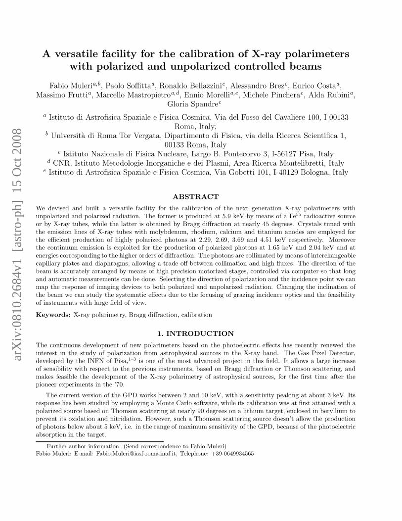
In Fig. 2(a) we report the ratio k for the diffraction on the plane 002 of a fluorite crystal (CaF2), calculatedby Henke et al.7 For θ = 45◦, k = 0 and, according to Eq. 2, the degree of polarization P = 1, as shown in
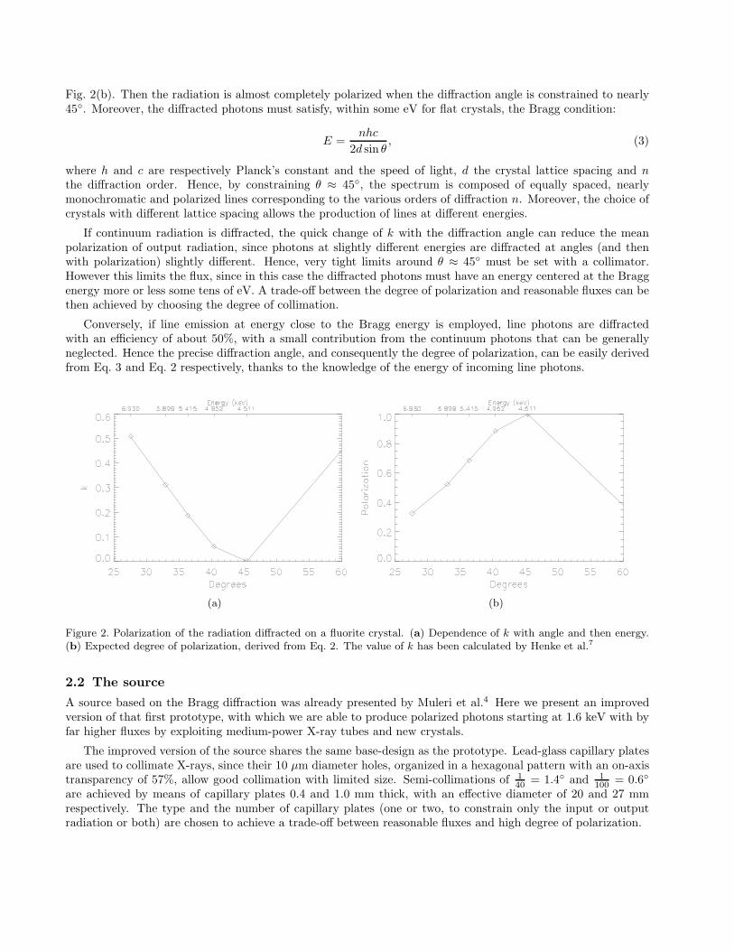
Fig. 2(b). Then the radiation is almost completely polarized when the diffraction angle is constrained to nearly45◦. Moreover, the diffracted photons must satisfy, within some eV for flat crystals, the Bragg condition:
E =nhc
2d sin θ, (3)
where h and c are respectively Planck’s constant and the speed of light, d the crystal lattice spacing and nthe diffraction order. Hence, by constraining θ ≈ 45◦, the spectrum is composed of equally spaced, nearlymonochromatic and polarized lines corresponding to the various orders of diffraction n. Moreover, the choice ofcrystals with different lattice spacing allows the production of lines at different energies.
If continuum radiation is diffracted, the quick change of k with the diffraction angle can reduce the meanpolarization of output radiation, since photons at slightly different energies are diffracted at angles (and thenwith polarization) slightly different. Hence, very tight limits around θ ≈ 45◦ must be set with a collimator.However this limits the flux, since in this case the diffracted photons must have an energy centered at the Braggenergy more or less some tens of eV. A trade-off between the degree of polarization and reasonable fluxes can bethen achieved by choosing the degree of collimation.
Conversely, if line emission at energy close to the Bragg energy is employed, line photons are diffractedwith an efficiency of about 50%, with a small contribution from the continuum photons that can be generallyneglected. Hence the precise diffraction angle, and consequently the degree of polarization, can be easily derivedfrom Eq. 3 and Eq. 2 respectively, thanks to the knowledge of the energy of incoming line photons.
(a) (b)
Figure 2. Polarization of the radiation diffracted on a fluorite crystal. (a) Dependence of k with angle and then energy.(b) Expected degree of polarization, derived from Eq. 2. The value of k has been calculated by Henke et al.7
2.2 The source
A source based on the Bragg diffraction was already presented by Muleri et al.4 Here we present an improvedversion of that first prototype, with which we are able to produce polarized photons starting at 1.6 keV with byfar higher fluxes by exploiting medium-power X-ray tubes and new crystals.
The improved version of the source shares the same base-design as the prototype. Lead-glass capillary platesare used to collimate X-rays, since their 10 µm diameter holes, organized in a hexagonal pattern with an on-axistransparency of 57%, allow good collimation with limited size. Semi-collimations of 1
40= 1.4◦ and 1
100= 0.6◦
are achieved by means of capillary plates 0.4 and 1.0 mm thick, with an effective diameter of 20 and 27 mmrespectively. The type and the number of capillary plates (one or two, to constrain only the input or outputradiation or both) are chosen to achieve a trade-off between reasonable fluxes and high degree of polarization.
Unpolarized X-rays are produced by commercial tubes with a maximum power of 50 W, manufactured byOxford Instruments. Three different tubes, with anode of molybdenum, rhodium and titanium, are employedto produce line emission at 2.29, 2.69 and 4.51 keV respectively. These energies are in accordance with the 45◦
Bragg diffraction from rhodium (001), germanium (111) and fluorite (CaF2, 220) crystals.7 Moreover, an ADP(101) and a PET (002) crystals are employed to produce polarized emission at 1.65 and 2.04 keV by means ofdiffraction of continuum radiation. In the table 1 the properties of the X-ray tubes and of the crystals availablein our facility are summarized.
Incident radiation (X-ray tube) Energy (keV) Crystal θ P
Continuum 1.65 ADP (NH4H2PO4, 101) 45◦ ∼1.0Continuum 2.04 PET (C(CH2OH)4, 002) 45◦ ∼1.0Lα Molybdenum (50 W) 2.293 Rhodium (001) 45.36◦ 0.9994Continuum 2.61 Graphite (002) 45◦ ∼1.0Lα Rhodium (50 W) 2.691 Germanium (111) 44.86◦ 0.9926Kα Calcium (200 mW) 3.692 Aluminum (111) 45.88◦ 0.9938Kα Titanium (50 W) 4.511 Fluorite CaF2 (220) 45.37◦ 0.9994
Table 1. X-ray tubes and crystals available in our facility. The low power calcium tube is employed with the firstprototype of source but it is shown in Table because can be mounted on the mechanical assembly described in Sec. 3. Forthe diffraction on ADP, PET and graphite crystals, continuum radiation produced by any tube can be employed since noline emission in accordance with the diffraction at 45 degrees is available. In this case, the energy and the polarization inTable are referred to the photons diffracted at 45◦. Only the energies corresponding to the first order of diffraction arereported, but each crystal can produce polarized radiation even at higher orders and, hence, at energies which are integermultiple of the first order. Polarization from calculation performed by Henke et al.7
Since the choice of the diffracting crystal allows to produce polarized radiation at different energies, wemounted each crystal in a different aluminum case to easily manage and change them. An important differencebetween the prototype and the improved version of the source is that in the latter we mounted each crystalcase on a manual stage which allows two axes tilt regulation in the range ±3◦ (see Fig. 3(a)). The stage isthen mounted on a central body (see Fig. 3(b)) and it is regulated to achieve the best alignment to the Braggcondition by means of optical and X-ray measurements. In the first case, a mirror mounted on the case of thecrystal is employed to reach the optimum angle between the crystal and the collimators, which are partiallyreflective. Then the inclination is refined with X-ray measurement to reach the highest flux.
We added two standard gas connectors in the central body (see Fig. 5) on the top and bottom side of thesource for helium flowing to reduce air absorption which heavily affects low energy photons. For the same reason,we reduced to the minimum the path of the photons.
The collimators also are mounted on an aluminum case, since their choice allows to achieve a trade-off betweenhigh fluxes and clean spectra. Two issues can indeed detach the output radiation from the ideal condition ofmonochromatic and highly polarized photons. The first one is that radiation can be scattered at nearly 90◦ onthe crystal or on its case and then photons not at the Bragg energy can emerge from the source. The second issueis that the input radiation is partially absorbed in the crystal (and in the aluminum case) and then unpolarizedfluorescence emission is produced. This problem is especially important when 1.65 keV polarized photons areproduced, since the aluminum Kα fluorescence is at 1.5 keV, and with the fluorite crystal, since the 3.7 Kαfluorescence of calcium has a comparable energy (and hence absorption) with respect to the polarized photonsat 4.5 keV produced with diffraction on that crystal.
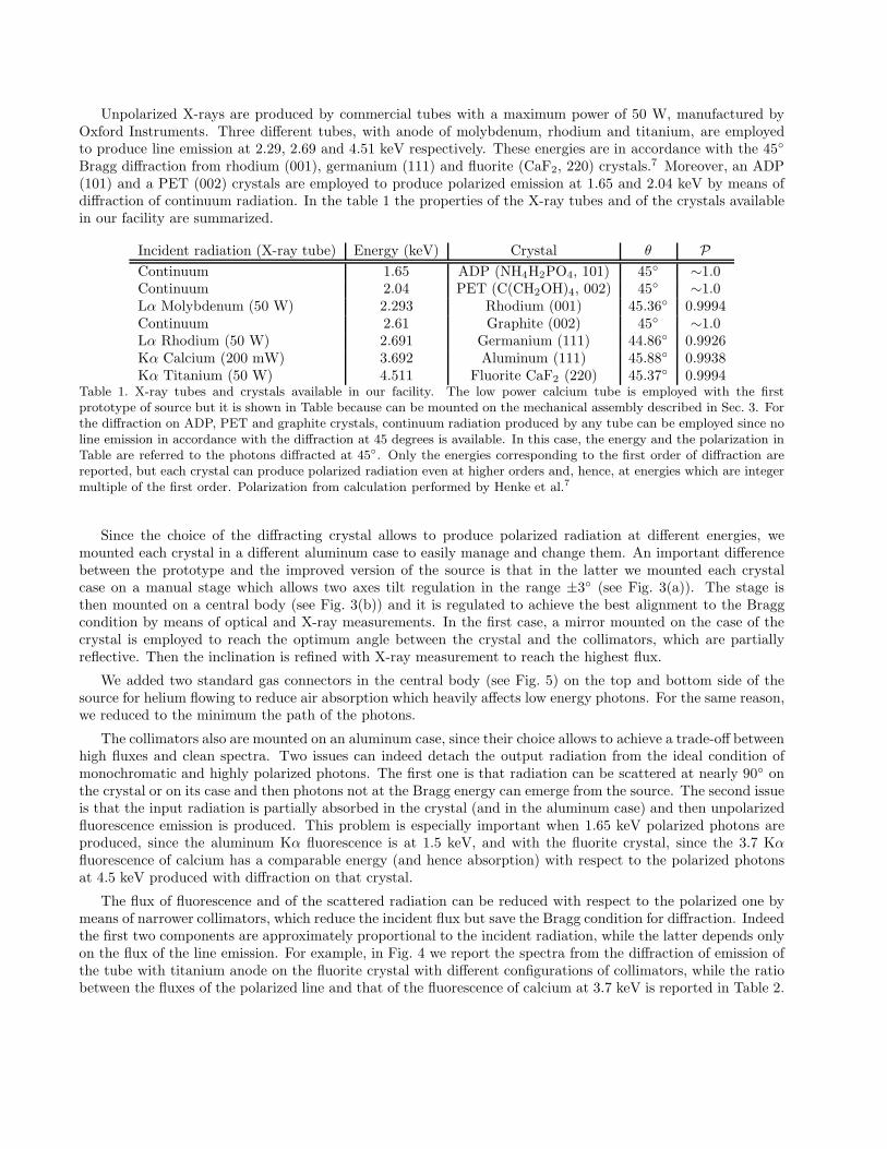
The flux of fluorescence and of the scattered radiation can be reduced with respect to the polarized one bymeans of narrower collimators, which reduce the incident flux but save the Bragg condition for diffraction. Indeedthe first two components are approximately proportional to the incident radiation, while the latter depends onlyon the flux of the line emission. For example, in Fig. 4 we report the spectra from the diffraction of emission ofthe tube with titanium anode on the fluorite crystal with different configurations of collimators, while the ratiobetween the fluxes of the polarized line and that of the fluorescence of calcium at 3.7 keV is reported in Table 2.
(a) (b)
Figure 3. (a) The manual stage on which each crystal is mounted. It allows two axes tilt regulation in the range ±3◦ andthen an optimum alignment to the Bragg condition. The aluminum case of the crystal is below the stage. (b) The crystalmounted on the central body of the source. The stage which allows the tilt regulation is hidden in the cover on the left.A capillary plate, used as collimator, is visible on the right in its case. The threaded hole on the top is for helium flowingto reduce the air absorption.
(a) (b)
Figure 4. Spectrum of the polarized source when the X-ray tube with titanium anode and the fluorite crystal are employed.The spectrum is measured with an Amptek XR100CR Si-PIN detector, with 213 eV resolution at 5.9 keV. Note that theflux of the line at 4.5 keV (at about channel 410) has been multiplied by 0.1. The peak in the middle is the fluorescenceof the calcium, while the peak on the left, at about 250 ch, is the escape peak of the line at 4.5 keV from the silicondetector. (a) One collimator with 1
40is employed to constrain the direction of diffracted photons. (b) The same as (a),
but when a 1
40and a 1
100collimators are employed to constrain the direction of input and output radiation respectively .
Input collimator Output collimator Fluxpolarized (c/s) Fluxfluorescence (c/s) Ratio
— 1
401073.7±3.0 18.04±0.47 ∼60
1
40
1
100458.38±0.79 1.046±0.072 ∼440
Table 2. Ratio between the fluxes of the polarized line at 4.5 keV and that of the fluorescence one at 3.7 keV for the samecrystal and X-ray tube, but for different configurations of collimators.

The complete source, composed by the polarizer and the X-ray tube, is shown in Fig. 5 mounted on the me-chanical assembly described in Sec. 3. The cooling of the tube is performed with four fans and, if its temperatureincreases above a determined threshold, it is turned off.
(a) (b)
Figure 5. The polarized source mounted on the mechanical assembly described in Sec. 3.
We have focused our attention to the first order of diffraction, since in this case the line emission of the tubesis in accordance with the diffraction at nearly 45◦. However the continuum radiation produced by the X-raytube by bremsstrahlung can be employed to produce also high energy and polarized radiation exploiting higherorders of diffraction, i.e. at energies which are integer multiple of the energy of the first order (see Table 1). Themedium power X-ray tubes can be very efficiently employed at this aim, since the high voltage (and hence themaximum energy of the photons produced) can be controlled independently from the current (and hence fromthe flux of the photons). Then, to produce polarized photons at 9 keV exploiting the second order of diffractionfrom fluorite, we can set the high voltage at 13 kV, i.e. just below the energy of the third order of diffraction,and then change the current to increase the flux up to 1 mA.
In Fig. 6 we show the spectrum obtained with diffraction of continuum radiation on the PET crystal. Thefirst five orders are visible with a relative peak heights which depend mainly on the different efficiency of thediffraction for each order and on the spectrum of the unpolarized incident radiation. Helium flowing was employedto avoid absorption of low energy photons. The rate of the lines are reported in Table 3.
Flux (c/s) Flux (c/s)
2.04 keV - I order 224.0±1.5 8.16 keV - IV order 13.44±0.434.08 keV - II order 73.5±1.0 10.20 keV - V order 7.41±0.276.12 keV - III order 17.10±0.39
Table 3. Main characteristics of the spectrum obtained with the polarized source by diffracting continuum radiation onthe PET crystal.
3. THE MECHANICAL ASSEMBLY
The polarized source described in Sec. 2.2 allows to overcome the problem of the measurement of the low energyperformances of the GPD, since photons with energy as low as 1.65 keV can be produced. The next improvementis then a systematic study of the sensibility of the GPD with a space-controlled beam. In particular, we want toexplore:

Figure 6. Continuum radiation diffracted on the PET crystal. Input radiation is obtained with the X-ray tube withtitanium anode (15 kV, 0.5 mA). The first five orders of diffraction are visible. The low energy peak (at about channel50) is due to background in the detector.
• the response on all the surface of the detector, since the GPD can also perform imaging on extended sources(XY-mapping);
• the correlation between the direction and the reconstructed angle of polarization (angle reconstruction);
• the study of the response to inclined beams, due to the focusing of grazing incidence optics or to large fieldof view instruments (inclined measurements).
We employed the Bragg diffraction sources described above and high precision motorized stages, manufacturedby Newport, to built a facility to perform these tasks. In addition to the Bragg sources (the prototype and theimproved version), we interfaced even unpolarized sources with the facility. In summary, we can produce:
• a collimated and, in case, diaphragmed polarized and nearly monochromatic beam, produced by means ofBragg diffraction. We can employ the prototype source at 3.7 keV or the improved version at 1.65, 2.04,2.29, 2.69 and 4.51 keV. The higher orders of diffraction are also available.
• collimated and/or diaphragmed unpolarized radiation at 5.89 and 6.49 keV by means of a Fe55 radioactivesource.
• collimated and/or diaphragmed unpolarized radiation at about 2.29, 2.69, 4.51 keV by means of directemission from X-ray tubes.
The mechanical assembly is designed to perform automatically and subsequently the measurements listedabove, i.e. XY-mapping, angle reconstruction and inclined measurements, for each source. The detector ismounted on a platform which can be rotated, inclined and moved with respect to the beam with eight motorizedstages and two manual ones. Moreover, the source is mounted on a rail with a graduated scale which allows itsquick movement when maintenance operations are performed on the tower supporting the detector (see fig. 7).The facility is mounted on an optical table in a room, shielded by X-ray radiation with a 1 mm of lead.
The stages are divided into two groups. The first one includes five motorized stages which actually changethe direction of the detector with respect to the beam, while the second group is employed to align the beamwith the detector. In the former group there are (see fig. 8):
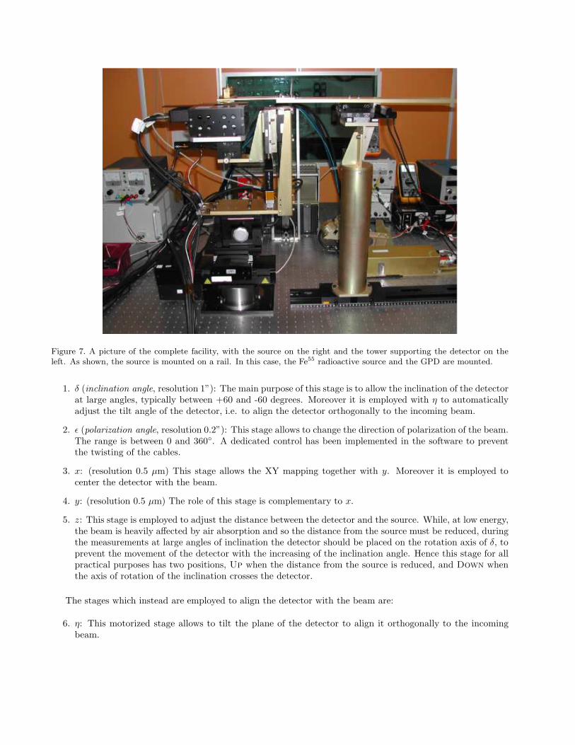
Figure 7. A picture of the complete facility, with the source on the right and the tower supporting the detector on theleft. As shown, the source is mounted on a rail. In this case, the Fe55 radioactive source and the GPD are mounted.
1. δ (inclination angle, resolution 1”): The main purpose of this stage is to allow the inclination of the detectorat large angles, typically between +60 and -60 degrees. Moreover it is employed with η to automaticallyadjust the tilt angle of the detector, i.e. to align the detector orthogonally to the incoming beam.
2. ǫ (polarization angle, resolution 0.2”): This stage allows to change the direction of polarization of the beam.The range is between 0 and 360◦. A dedicated control has been implemented in the software to preventthe twisting of the cables.
3. x: (resolution 0.5 µm) This stage allows the XY mapping together with y. Moreover it is employed tocenter the detector with the beam.
4. y: (resolution 0.5 µm) The role of this stage is complementary to x.
5. z: This stage is employed to adjust the distance between the detector and the source. While, at low energy,the beam is heavily affected by air absorption and so the distance from the source must be reduced, duringthe measurements at large angles of inclination the detector should be placed on the rotation axis of δ, toprevent the movement of the detector with the increasing of the inclination angle. Hence this stage for allpractical purposes has two positions, Up when the distance from the source is reduced, and Down whenthe axis of rotation of the inclination crosses the detector.
The stages which instead are employed to align the detector with the beam are:
6. η: This motorized stage allows to tilt the plane of the detector to align it orthogonally to the incomingbeam.
ε
v
δ
z
ηλ
x
y
Detector
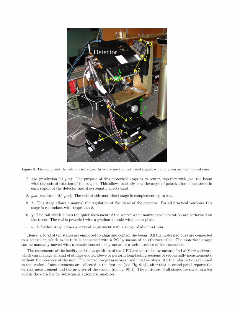
Figure 8. The name and the role of each stage. In yellow are the motorized stages, while in green are the manual ones.
7. xso (resolution 0.1 µm): The purpose of this motorized stage is to center, together with yso, the beamwith the axis of rotation of the stage ǫ. This allows to study how the angle of polarization is measured ineach region of the detector and if systematic effects exist.
8. yso (resolution 0.1 µm): The role of this motorized stage is complementary to xso.
9. λ: This stage allows a manual tilt regulation of the plane of the detector. For all practical purposes thisstage is redundant with respect to δ.
10. χ: The rail which allows the quick movement of the source when maintenance operation are performed onthe tower. The rail is provided with a graduated scale with 1 mm pitch.
—. ν: A further stage allows a vertical adjustment with a range of about 44 mm.
Hence, a total of ten stages are employed to align and control the beam. All the motorized ones are connectedto a controller, which in its turn is connected with a PC by means of an ethernet cable. The motorized stagescan be manually moved with a remote control or by means of a web interface of the controller.
The movements of the facility and the acquisition of the GPD are controlled by means of a LabView software,which can manage all kind of studies quoted above to perform long-lasting sessions of sequentially measurements,without the presence of the user. The control program is organized into two steps. All the informations requiredto the session of measurements are collected in the first one (see Fig. 9(a)), after that a second panel reports thecurrent measurement and the progress of the session (see fig. 9(b)). The positions of all stages are saved in a logand in the data file for subsequent automatic analyzes.

(a) (b)
Figure 9. User interface of the program which controls the motorized stages. (a) Interface in which all the informationsare at first collected. (b) The panel which allows to control the state of the measurements.
4. PRELIMINARY RESULTS
A test of the facility was performed by using an Amptek XR100CR Si-PIN detector to map the 3.7 keV Kαcalcium line diffracted by the aluminum crystal. A diaphragm of 1 mm is used in front of the detector to samplethe beam.
In Fig. 10 the map of the rate of the flux is shown on a grid of 7×5 points. The beam is elliptical, with amajor axis (in the direction of polarization) of about 4 mm FWHM. In the perpendicular direction, the extensionof the beam is 2 mm FWHM. Since the diffraction should not change the section of the beam, it should reflectthe shape of cathode of the X-ray tube.
The properties of the line are identical for all the central 7×3 points, where the counts are sufficient fora reliable fit. In Fig. 11(a) we report the FWHM of the line for the 7×3 measurements, which are clearlyconsistent within errors. In the Fig. 11(b) instead, the energy of the line is shown. In this case a increasing trendis present, even if it can be imputed to changes in the silicon detector, since it follows the sequence in which themeasurements were done.
5. CONCLUSION
We have designed and built a facility for the calibration of the next generation X-ray polarimeters. Polarizedphotons are produced by means of Bragg diffraction at nearly 45 degrees. Following the good results of aprototype source which allows the diffraction of continuum or line emission on aluminum or graphite crystals,4
we have developed an improved version of the source which can exploit also the diffraction on ADP, PET,rhodium, germanium and fluorite crystals. Thanks to X-ray tubes with anodes tuned with these crystals, we canvery efficiently produce almost completely polarized photons at 2.29, 2.69 and 4.51 keV. Moreover, continuumemission is employed to generate highly polarized radiation at 1.65 and 2.04 keV. Both the prototype andthe improved version of the polarized sources have been interfaced, together with unpolarized sources, with amechanical assembly which, thanks to motorized stages controlled via PC, allows calibration measurements withspace-controlled beams. In particular the facility is optimized for mapping the response of imaging devices toboth polarized and unpolarized radiation, with inclined or orthogonal beams. This facility will be soon employedfor the calibration of the Gas Pixel Detector.

Figure 10. Map (7×5 points) of the the rate of the beam produced with the Bragg diffraction at 3.7 keV. The beam iselliptical, with a major axis (in the direction of polarization) of about 4 mm FWHM.
(a) (b)
Figure 11. FWHM (a) and energy (b) variation of the 3.7 keV Kα calcium line diffracted by the aluminum crystal andmeasured with an Amptek XR100CR Si-PIN detector. In the x-axis, the index of the 7×3=21 measurements is reported.
Acknowledgments
FM acknowledges financial support from Agenzia Spaziale Italiana (ASI) under contract ASI I/088/06/0.
REFERENCES
[1] Costa, E., Soffitta, P., Bellazzini, R., Brez, A., Lumb, N., and Spandre, G., “An efficient photoelectric X-raypolarimeter for the study of black holes and neutron stars,” Nature 411, 662–665 (2001).
[2] Bellazzini, R., Spandre, G., Minuti, M., Baldini, L., Brez, A., Cavalca, F., Latronico, L., Omodei, N., Massai,M. M., Sgro’, C., Costa, E., Soffitta, P., Krummenacher, F., and de Oliveira, R., “Direct reading of chargemultipliers with a self-triggering CMOS analog chip with 105 k pixels at 50 µm pitch,” Nuclear Instruments
and Methods in Physics Research A 566, 552–562 (2006).

[3] Bellazzini, R., Spandre, G., Minuti, M., Baldini, L., Brez, A., Latronico, L., Omodei, N., Razzano, M.,Massai, M. M., Pesce-Rollins, M., Sgro, C., Costa, E., Soffitta, P., Sipila, H., and Lempinen, E., “A sealedGas Pixel Detector for X-ray astronomy,” Nuclear Instruments and Methods in Physics Research A 579,853–858 (2007).
[4] Muleri, F., Soffitta, P., Bellazzini, R., Brez, A., Costa, E., Fabiani, S., Frutti, M., Minuti, M., Negri, M. B.,Pascale, P., Rubini, A., Sindoni, G., and Spandre, G., “A very compact polarizer for an X-ray polarimetercalibration,” in [Proc. SPIE ], 6686, 668610 (2007).
[5] Muleri, F., Soffitta, P., Baldini, L., Bellazzini, R., Bregeon, J., Brez, A., Costa, E., Frutti, M., Latronico, L.,Minuti, M., Negri, M. B., Omodei, N., Pesce-Rollins, M., Pinchera, M., Razzano, M., Rubini, A., Sgro, C.,and Spandre, G., “Low energy polarization sensitivity of the Gas Pixel Detector,” Nuclear Instruments and
Methods in Physics Research A 584, 149–159 (2008).
[6] Evans, K. D., Hall, R., and Lewis, M., “The calibration of Bragg X-ray analyser crystals for use as polarime-ters in X-ray astronomy.,” Space Science Instrumentation 3, 163–169 (1977).
[7] Henke, B. L., Gullikson, E. M., and Davis, J. C., “X-Ray Interactions: Photoabsorption, Scattering, Trans-mission, and Reflection at E = 50-30,000 eV, Z = 1-92,” Atomic Data and Nuclear Data Tables 54, 181(1993).


![Unpolarized Drell-Yan at Fermilab: (~70 collaborators) → SeaQuest [E-906]: (USA, Japan, Taiwan) → science run: Feb 2014 — spring/summer 2016 Polarized.](https://static.fdocuments.us/doc/165x107/56649ebf5503460f94bc9ee9/unpolarized-drell-yan-at-fermilab-70-collaborators-seaquest-e-906.jpg)


![CP-Conserving Unparticle Phase Effects on the Unpolarized ... filearXiv:0801.1490v2 [hep-ph] 14 May 2008 CP-Conserving Unparticle Phase Effects on the Unpolarized and Polarized Direct](https://static.fdocuments.us/doc/165x107/5d56161a88c993225d8b678b/cp-conserving-unparticle-phase-eects-on-the-unpolarized-08011490v2-hep-ph.jpg)
