WITH INSPECTION AND MAINTENANCE ... - Walker Magnet manual.pdf · 4 O.S. Walker Inc., NEO Permanent...
29
• Always stay clear of the load. • Never lift loads over people or in close proximity to people. • Never attempt to operate either of these magnets until you have read and understand this Operator’s Manual. DANGER O.S. WALKER WALKER NEO-HV-250, NEO-HV-500, NEO-HV-1000 WITH INSPECTION AND MAINTENANCE INSTRUCTIONS OPERATOR’S MANUAL AND SAFETY INSTRUCTIONS NEO Permanent Lifting Magnets Models: NEO-125, NEO-250, NEO-500, NEO-1000, NEO-2000 NEO-HV-250, NEO-HV-500, NEO-HV-1000 NEO-125, NEO-250, NEO500, NEO-1000 & NEO-2000
Transcript of WITH INSPECTION AND MAINTENANCE ... - Walker Magnet manual.pdf · 4 O.S. Walker Inc., NEO Permanent...
• Always stay clear of the load.
• Never lift loads over people or in close proximity to people.
• Never attempt to operate either of these magnets until you have read and understand this Operator’s Manual.
DANGER
O.S. WALKERWALKER
NEO-HV-250, NEO-HV-500, NEO-HV-1000
WITH INSPECTION AND MAINTENANCE INSTRUCTIONS
OPERATOR’S MANUALAND
SAFETY INSTRUCTIONSNEO Permanent Lifting Magnets
Models: NEO-125, NEO-250, NEO-500, NEO-1000, NEO-2000 NEO-HV-250, NEO-HV-500, NEO-HV-1000
NEO-125, NEO-250, NEO500, NEO-1000 & NEO-2000
2 O.S. Walker Inc., NEO Permanent Lifting Magnets
CONTENTSINTRODUCTION ................................................................................................................................... 2SAFETY INSTRUCTIONS .................................................................................................................... 3
GENERAL SAFETY RULES ......................................................................................................................................3RECOGNIZE SAFETY INFORMATION ....................................................................................................................4UNSAFE LIFTING APPLICATIONS FOR YOUR MAGNET ......................................................................................4WAYS TO AVOID A REDUCTION OF LIFTING CAPACITY .....................................................................................5ADDITIONAL WARNINGS ........................................................................................................................................5SAFETY PERSON ....................................................................................................................................................5
IMPORTANT FACTS FOR THE OPERATION OF LIFT MAGNETS .................................................... 6RECOMMENDED LIFTING PROCEDURES ...................................................................................... 10GUIDELINES FOR THE REDUCTION OF THE RATED LIFTING CAPACITY ...................................11
NEO-125 LIFTING GUIDELINES (PLATE) .............................................................................................................12NEO-125 LIFTING GUIDELINES (ROUND BARS) ...............................................................................................13NEO-250 LIFTING GUIDELINES (PLATE) .............................................................................................................14NEO-250 LIFTING GUIDELINES (ROUND BARS & PIPES) ................................................................................15NEO-500 LIFTING GUIDELINES (PLATE) .............................................................................................................16NEO-500 LIFTING GUIDELINES (ROUND BARS & PIPES) ................................................................................17NEO-1000 LIFTING GUIDELINES (PLATE) ...........................................................................................................18NEO-1000 LIFTING GUIDELINES (ROUND BARS & PIPES) ..............................................................................19NEO-2000 LIFTING GUIDELINES (PLATE) ...........................................................................................................20NEO-2000 LIFTING GUIDELINES (ROUND BARS & PIPES) ..............................................................................21
INSPECTION AND MAINTENANCE INSTRUCTIONS ...................................................................... 22EVERY LIFT ............................................................................................................................................................22DAILY.......................................................................................................................................................................22WEEKLY ..................................................................................................................................................................22
SPECIFICATION & SPARE PARTS LIST ........................................................................................... 23NEO-HV 250, NEO-HV 500, NEO-HV 1000........................................................................................ 24
HV INSPECTION AND MAINTENANCE .................................................................................................................27DAILY ................................................................................................................................................................27WEEKLY ...........................................................................................................................................................27ANNUALLY .......................................................................................................................................................27HV SPARE PARTS LIST ...................................................................................................................................28
Thank you for purchasing this O.S. Walker Product. If used and maintained properly, it should serve you for many years. Thousands of Walker lift magnets are in service today doing safe, fast, and effi cient magnetic material handling applications. It is often the only way for one person to load, transport, and unload material.
Walker Products have proven to be among the best designed and safest in our indus-try. However, used improperly, any NEO or NEO-HV lifting magnet can be rendered ineffi cient and unsafe. Therefore, it is absolutely essential that anyone who uses this lifting magnet and is responsible for its application be trained on how to use it correctly.
READ THIS MANUAL CAREFULLY AND WATCH THE SAFETY VIDEO TO LEARN HOW TO OPERATE AND MAINTAIN YOUR MAGNET. FAILURE TO DO SO COULD RESULT IN SERIOUS INJURY OR DEATH, TO YOURSELF AND PEOPLE IN THE AREA. THIS MANUAL AND SAFETY VIDEO SHOULD BE CONSIDERED A PERMANENT PART OF YOUR MAGNET AND SHOULD ALWAYS BE AVAILABLE TO ALL OPERATORS AND REMAIN WITH THE MAGNET IF IT IS RE-SOLD. Additional copies of this OPERATOR’S manual ARE AVAILABLE. JUST CALL 1-800-962-4638 AND REQUEST ADDITIONAL COPIES OF MANUAL #37-DD14493.
INTRODUCTION
3O.S. Walker Inc., NEO Permanent Lifting Magnets
SAFETY INSTRUCTIONSGENERAL SAFETY RULES
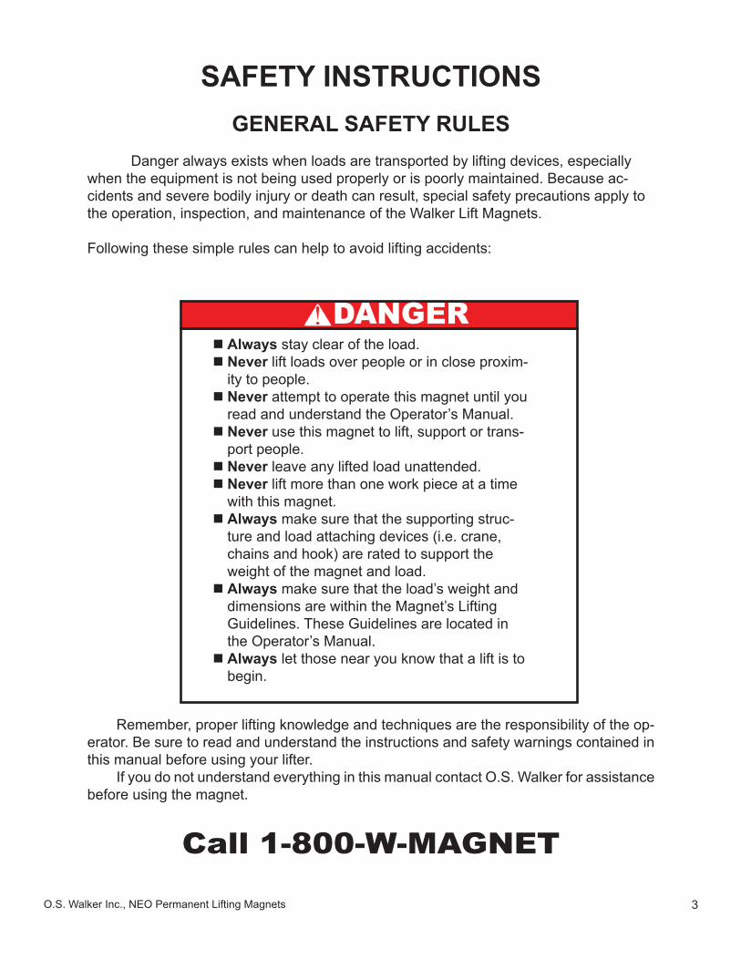
Danger always exists when loads are transported by lifting devices, especially when the equipment is not being used properly or is poorly maintained. Because ac-cidents and severe bodily injury or death can result, special safety precautions apply to the operation, inspection, and maintenance of the Walker Lift Magnets.
Following these simple rules can help to avoid lifting accidents:
Remember, proper lifting knowledge and techniques are the responsibility of the op-erator. Be sure to read and understand the instructions and safety warnings contained in this manual before using your lifter.
If you do not understand everything in this manual contact O.S. Walker for assistance before using the magnet.
Call 1-800-W-MAGNET
Always stay clear of the load. Never lift loads over people or in close proxim-ity to people. Never attempt to operate this magnet until you read and understand the Operator’s Manual. Never use this magnet to lift, support or trans-port people. Never leave any lifted load unattended. Never lift more than one work piece at a time with this magnet. Always make sure that the supporting struc-ture and load attaching devices (i.e. crane, chains and hook) are rated to support the weight of the magnet and load. Always make sure that the load’s weight and dimensions are within the Magnet’s Lifting Guidelines. These Guidelines are located in the Operator’s Manual. Always let those near you know that a lift is to begin.
DANGER
4 O.S. Walker Inc., NEO Permanent Lifting Magnets
SAFETY INSTRUCTIONSRECOGNIZE SAFETY INFORMATION
UNSAFE LIFTING APPLICATIONS FOR YOUR MAGNET
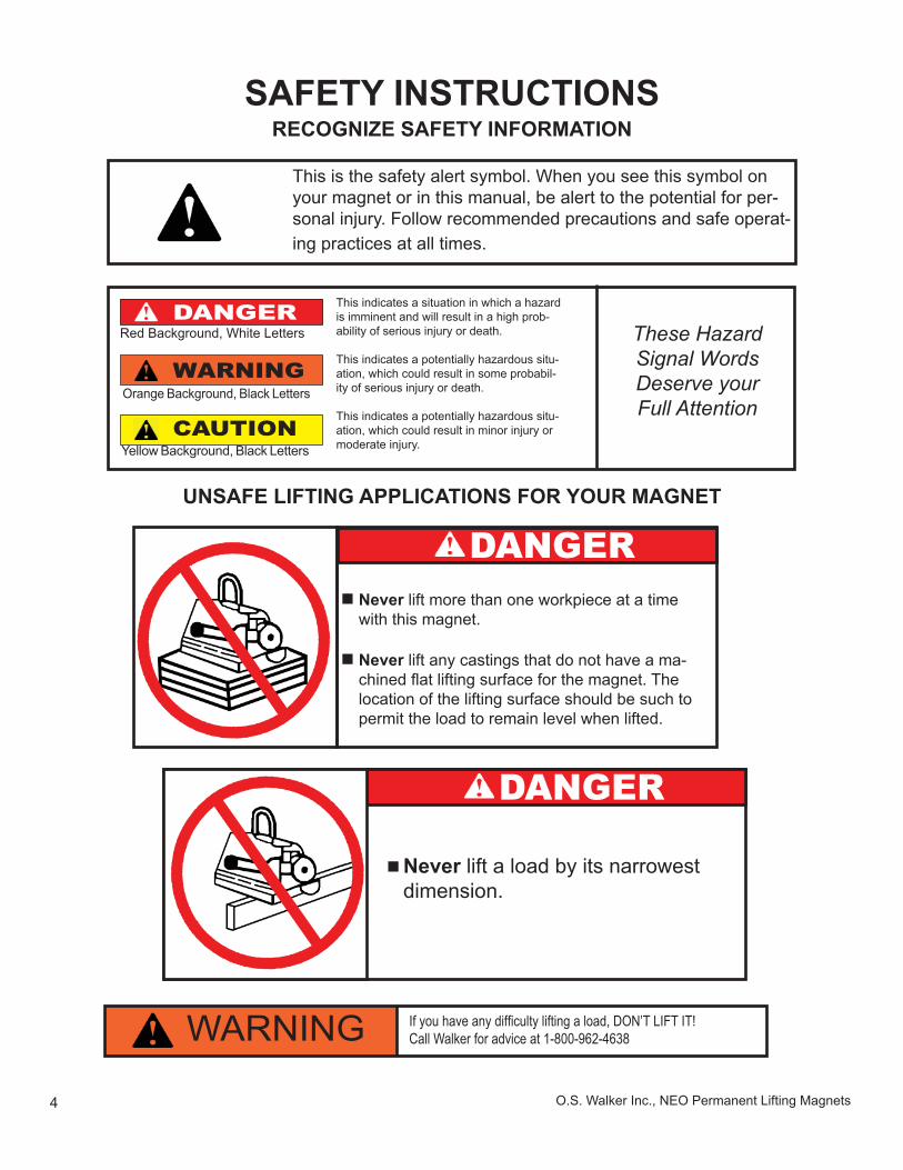
This is the safety alert symbol. When you see this symbol on your magnet or in this manual, be alert to the potential for per-sonal injury. Follow recommended precautions and safe operat-ing practices at all times.
DANGER Never lift more than one workpiece at a time with this magnet.
Never lift any castings that do not have a ma-chined fl at lifting surface for the magnet. The location of the lifting surface should be such to permit the load to remain level when lifted.
Red Background, White Letters
Orange Background, Black Letters
Yellow Background, Black Letters
This indicates a situation in which a hazard is imminent and will result in a high prob-ability of serious injury or death.
This indicates a potentially hazardous situ-ation, which could result in some probabil-ity of serious injury or death.
This indicates a potentially hazardous situ-ation, which could result in minor injury or moderate injury.
These Hazard Signal Words Deserve your Full Attention
DANGER
WARNING
CAUTION
Never lift a load by its narrowest dimension.
DANGER
If you have any diffi culty lifting a load, DON’T LIFT IT!Call Walker for advice at 1-800-962-4638WARNING
5O.S. Walker Inc., NEO Permanent Lifting Magnets
SAFETY INSTRUCTIONSWAYS TO AVOID A REDUCTION OF LIFTING CAPACITY
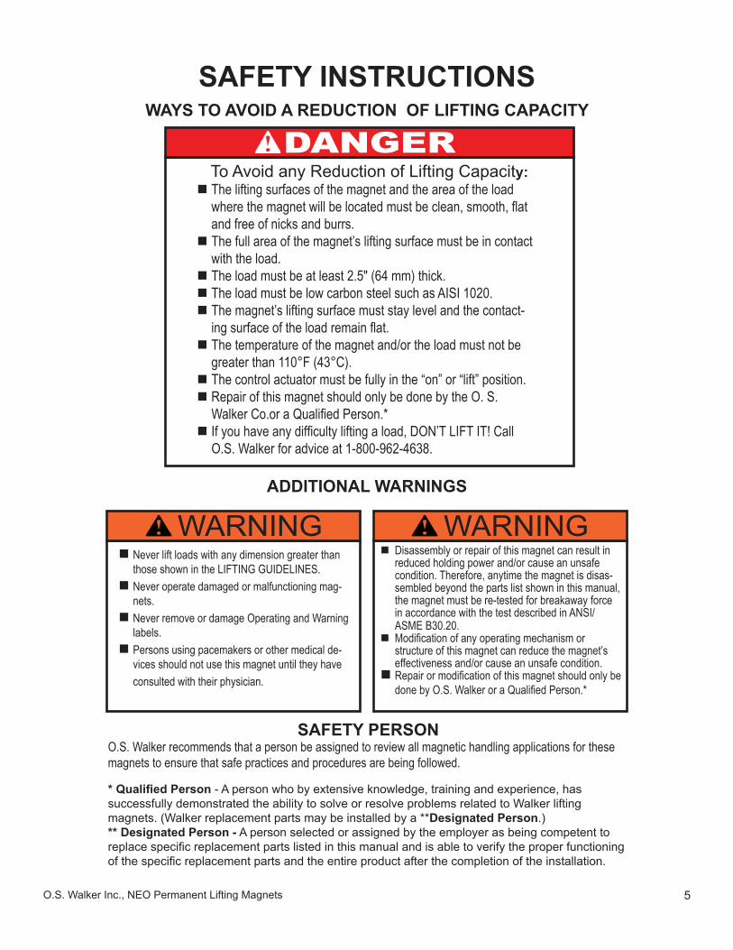
Never lift loads with any dimension greater than those shown in the LIFTING GUIDELINES. Never operate damaged or malfunctioning mag-nets. Never remove or damage Operating and Warning labels. Persons using pacemakers or other medical de-vices should not use this magnet until they have consulted with their physician.
SAFETY PERSONO.S. Walker recommends that a person be assigned to review all magnetic handling applications for these magnets to ensure that safe practices and procedures are being followed.
To Avoid any Reduction of Lifting Capacity: The lifting surfaces of the magnet and the area of the load where the magnet will be located must be clean, smooth, fl at and free of nicks and burrs. The full area of the magnet’s lifting surface must be in contact with the load. The load must be at least 2.5" (64 mm) thick. The load must be low carbon steel such as AISI 1020. The magnet’s lifting surface must stay level and the contact-ing surface of the load remain fl at. The temperature of the magnet and/or the load must not be greater than 110°F (43°C). The control actuator must be fully in the “on” or “lift” position. Repair of this magnet should only be done by the O. S. Walker Co.or a Qualifi ed Person.* If you have any diffi culty lifting a load, DON’T LIFT IT! Call O.S. Walker for advice at 1-800-962-4638.
* Qualifi ed Person - A person who by extensive knowledge, training and experience, has successfully demonstrated the ability to solve or resolve problems related to Walker lifting magnets. (Walker replacement parts may be installed by a **Designated Person.)** Designated Person - A person selected or assigned by the employer as being competent to replace specifi c replacement parts listed in this manual and is able to verify the proper functioning of the specifi c replacement parts and the entire product after the completion of the installation.
ADDITIONAL WARNINGS
WARNING Disassembly or repair of this magnet can result in reduced holding power and/or cause an unsafe condition. Therefore, anytime the magnet is disas-sembled beyond the parts list shown in this manual, the magnet must be re-tested for breakaway force in accordance with the test described in ANSI/ASME B30.20. Modifi cation of any operating mechanism or structure of this magnet can reduce the magnet’s effectiveness and/or cause an unsafe condition. Repair or modifi cation of this magnet should only be done by O.S. Walker or a Qualifi ed Person.*
WARNING
DANGER
6 O.S. Walker Inc., NEO Permanent Lifting Magnets
IMPORTANT FACTS FOR THE OPERATION OF LIFT MAGNETS
LOAD CHARACTERISTICS OTHER THAN JUST WEIGHTMUST BE CONSIDERED IN ORDER TO DETERMINE
THE LOAD THAT ANY MAGNET CAN LIFT.
This statement is true for all lifting magnets because they all operate using the same funda-mental laws of physics. Magnetic power is often pictured as lines of magnetic force fl owing from north pole to south pole. Anything that limits the fl ow of these magnetic lines of force obviously reduces the magnet’s lifting capacity. There are many important factors, which limit the fl ow of these lines of force.
1. SURFACE CONDITIONSMagnetic lines of force do not fl ow easily through air. They need iron in order to fl ow freely; therefore, anything that creates a space or an air gap between a magnet and the load limits the fl ow of magnetic lines of force and, thus, reduces the lifting capacity of a magnet.
MAGNET’S LIFTING SURFACE CONDITION — The lifting surfaces of a magnet must be clean, smooth, fl at and free of nicks and burrs to minimize the air gap be-tween a magnet and the load. This magnet has been designed with soft, low carbon steel lifting surfaces in order to maximize the lifting capacity; therefore, special care must be taken to protect these surfaces. Follow the Inspection Instructions in this manual. Attaching or welding other materials to the lifting surfaces in order to reduce wear should not be done with this magnet because it will reduce the lifting capacity.
LOAD SURFACE CONDITION — Paper, dirt, rags, rust, paint, and scale act the same as air. Also, a rough surface fi nish on the load creates an air gap be-tween the magnet and load. Any of these conditions will reduce the magnet’s lifting capacity.
2. LOAD THICKNESSThe greater the number of lines of magnetic force fl owing from a magnet into the load, the greater the effectiveness of the magnet. The thicker the load, the more lines of mag-netic force are able to fl ow. After a certain thickness of load, no additional lines of force will fl ow because the magnet has reached its full capacity.
Thin material (load) means less iron available, and thus fewer lines of magnetic force fl ow from the magnet into the load. Therefore, the lifting capacity of the magnet is reduced. In some cases, the magnet will attract more than one thin plate of material when set on a stack of thin plates. DO NOT LIFT more than one plate at a time since the lower plate may not be held suffi ciently.
The lifting guidelines provide the user with what minimum thickness of load is re-quired to reach full lifting capacity. Below such thickness of load, the user must ac-cept the reduced lifting capacity of the magnet as shown in the guidelines.
7O.S. Walker Inc., NEO Permanent Lifting Magnets
3. LOAD ALLOYLow carbon steels, such as AISI 1020 steel, are nearly as good conductors of magnetic lines of force as pure iron. However, many other alloys contain non-magnetic materials, which re-duce the ability of magnetic lines of force to fl ow into the load. An alloy such as AISI 300 series of stainless steel is almost as poor a conductor of magnetic lines of force as air.
Type 416 stainless steel is considered magnetic, but it contains enough chromium so that a magnet can develop only one-half as much force on a type 416 stainless steel load as it can on a AISI 1020 steel load. Also, because of the carbon content, the force developed on cast iron is less than one-half of that developed on AISI 1020 steel. (Chilled cast iron further reduces the force to less than one-quarter.)
4. LOAD LENGTH OR WIDTHAs the length or width of a load increases, it ceases to remain fl at when lifted and the edges begin to droop. This drooping or sagging of the load can create an air gap between the load and the magnet. This is called peel. If this occurs, the lifting capacity of the magnet is greatly reduced.
For plate lifting, where drooping often occurs, rectangular shaped magnets must be positioned so that the length of the magnet is parallel to the width of the load.
5. POSITION OF MAGNET’S LIFTING SURFACEAs the position of the magnet’s lifting surface changes from horizontal to vertical, the lifting capacity of the magnet decreases. When the magnet’s lifting surfaces are vertical, the lifting capacity of the magnet is minimum and dependent upon the coeffi cient of friction between the magnet’s lifting surface and the load.
6. PORTION OF MAGNET SURFACE IN CONTACT WITH LOADThe full surface of the magnet must contact the load if the magnet is to achieve rated lift ca-pacity.
7. LOAD TEMPERATUREThe temperature of the load can cause damage to the magnet and, if high enough, can even change the magnetic characteristics of the load. For Standard Lift Magnets, Walker should be consulted if the load or air temperature exceeds 110° F (43° C).
8 O.S. Walker Inc., NEO Permanent Lifting Magnets
FOR FAST, EASY LIFTING WITH YOUR WALKERNEO-125, NEO-250, NEO-500,
NEVER attempt to turn the magnet on or offin the “Lifting Guidelines” section of this
on loads that are too thin will result in the
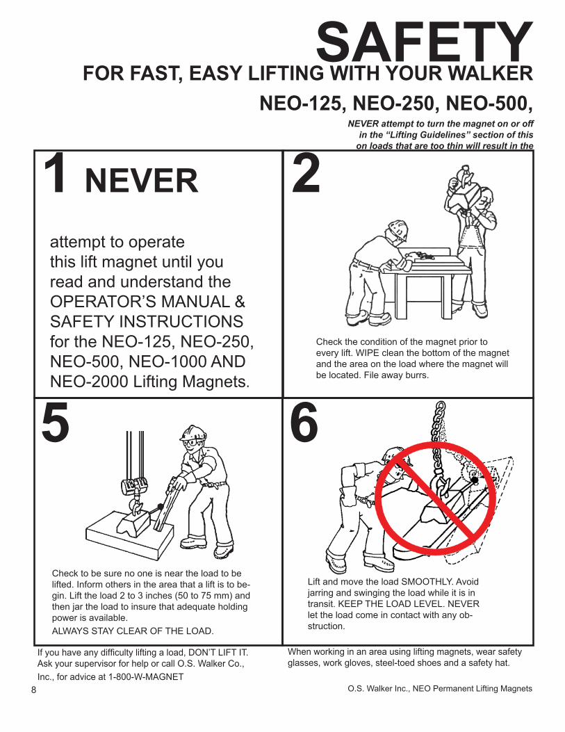
1 NEVERattempt to operatethis lift magnet until you read and understand the OPERATOR’S MANUAL &SAFETY INSTRUCTIONSfor the NEO-125, NEO-250, NEO-500, NEO-1000 AND NEO-2000 Lifting Magnets.
SAFETY
If you have any diffi culty lifting a load, DON’T LIFT IT. Ask your supervisor for help or call O.S. Walker Co., Inc., for advice at 1-800-W-MAGNET
When working in an area using lifting magnets, wear safety glasses, work gloves, steel-toed shoes and a safety hat.
2
Check the condition of the magnet prior to every lift. WIPE clean the bottom of the magnet and the area on the load where the magnet will be located. File away burrs.
5
Check to be sure no one is near the load to be lifted. Inform others in the area that a lift is to be-gin. Lift the load 2 to 3 inches (50 to 75 mm) and then jar the load to insure that adequate holding power is available.ALWAYS STAY CLEAR OF THE LOAD.
Lift and move the load SMOOTHLY. Avoid jarring and swinging the load while it is in transit. KEEP THE LOAD LEVEL. NEVER let the load come in contact with any ob-struction.
6
9O.S. Walker Inc., NEO Permanent Lifting Magnets
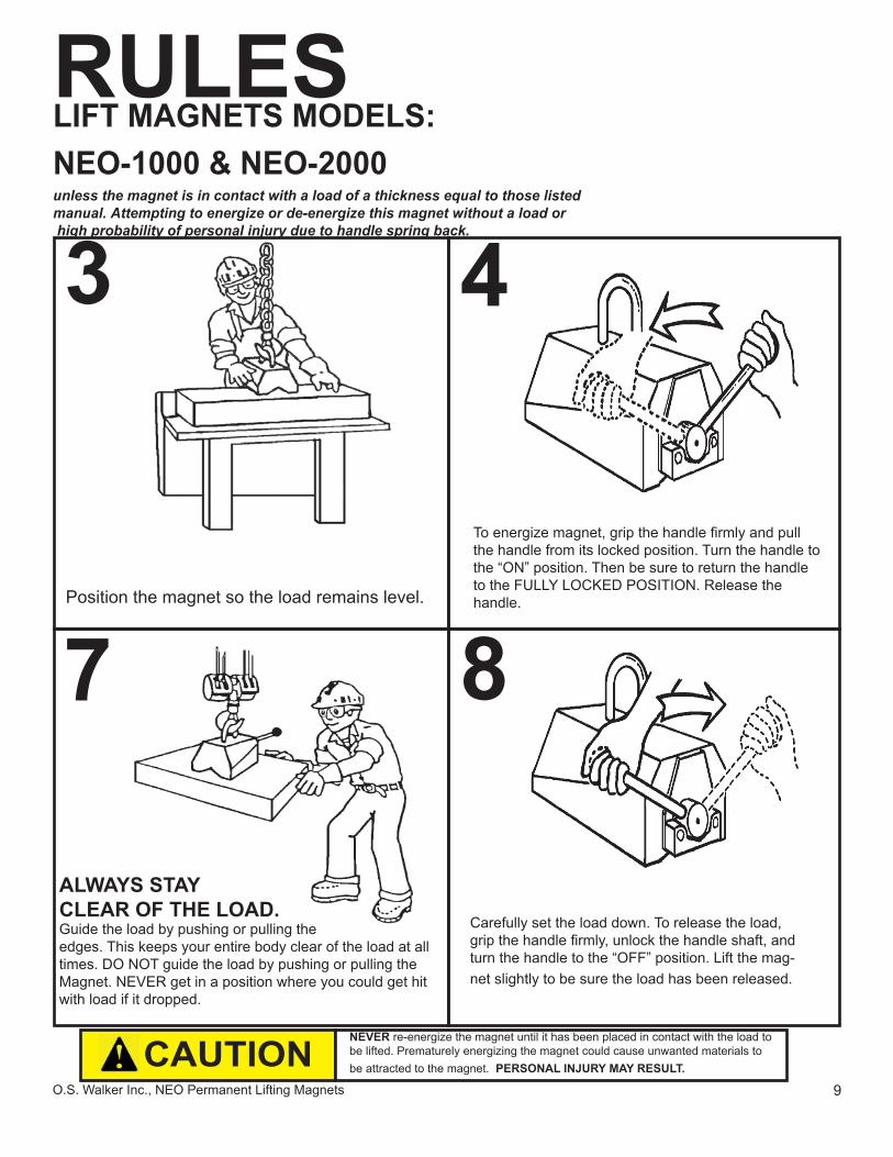
LIFT MAGNETS MODELS:NEO-1000 & NEO-2000unless the magnet is in contact with a load of a thickness equal to those listedmanual. Attempting to energize or de-energize this magnet without a load or high probability of personal injury due to handle spring back.
RULES
8
Carefully set the load down. To release the load, grip the handle fi rmly, unlock the handle shaft, and turn the handle to the “OFF” position. Lift the mag-net slightly to be sure the load has been released.
3
Position the magnet so the load remains level.
4
To energize magnet, grip the handle fi rmly and pull the handle from its locked position. Turn the handle to the “ON” position. Then be sure to return the handle to the FULLY LOCKED POSITION. Release the handle.
7
ALWAYS STAYCLEAR OF THE LOAD.Guide the load by pushing or pulling the edges. This keeps your entire body clear of the load at all times. DO NOT guide the load by pushing or pulling the Magnet. NEVER get in a position where you could get hit with load if it dropped.
NEVER re-energize the magnet until it has been placed in contact with the load to be lifted. Prematurely energizing the magnet could cause unwanted materials to be attracted to the magnet. PERSONAL INJURY MAY RESULT.CAUTION
10 O.S. Walker Inc., NEO Permanent Lifting Magnets
RECOMMENDED LIFTING PROCEDURES SAFETY HOOK LATCH
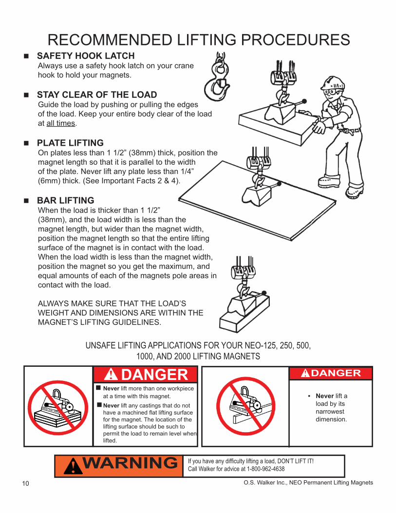
Always use a safety hook latch on your crane hook to hold your magnets.
STAY CLEAR OF THE LOADGuide the load by pushing or pulling the edges of the load. Keep your entire body clear of the load at all times.
PLATE LIFTINGOn plates less than 1 1/2” (38mm) thick, position the magnet length so that it is parallel to the width of the plate. Never lift any plate less than 1/4” (6mm) thick. (See Important Facts 2 & 4).
BAR LIFTINGWhen the load is thicker than 1 1/2” (38mm), and the load width is less than the magnet length, but wider than the magnet width, position the magnet length so that the entire lifting surface of the magnet is in contact with the load.When the load width is less than the magnet width, position the magnet so you get the maximum, and equal amounts of each of the magnets pole areas in contact with the load.
ALWAYS MAKE SURE THAT THE LOAD’S WEIGHT AND DIMENSIONS ARE WITHIN THE MAGNET’S LIFTING GUIDELINES.
UNSAFE LIFTING APPLICATIONS FOR YOUR NEO-125, 250, 500, 1000, AND 2000 LIFTING MAGNETS
If you have any diffi culty lifting a load, DON’T LIFT IT!Call Walker for advice at 1-800-962-4638WARNING
Never lift more than one workpiece at a time with this magnet.
Never lift any castings that do not have a machined fl at lifting surface for the magnet. The location of the lifting surface should be such to permit the load to remain level when lifted.
DANGER• Never lift a
load by its narrowest dimension.
DANGER
11O.S. Walker Inc., NEO Permanent Lifting Magnets
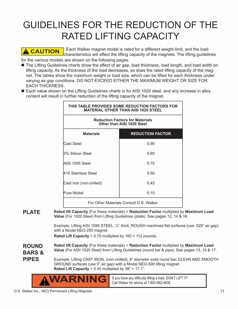
: Each Walker magnet model is rated for a different weight limit, and the load characteristics will affect the lifting capacity of the magnets. The lifting guidelines
for the various models are shown on the following pages. The Lifting Guidelines charts show the effect of air gap, load thickness, load length, and load width on lifting capacity. As the thickness of the load decreases, so does the rated lifting capacity of the mag-net. The tables show the maximum weight or load size, which can be lifted for each thickness under varying air gap conditions. DO NOT EXCEED EITHER THE MAXIMUM WEIGHT OR SIZE FOR EACH THICKNESS. Each value shown on the Lifting Guidelines charts is for AISI 1020 steel, and any increase in alloy content will result in further reduction of the lifting capacity of the magnet.
THIS TABLE PROVIDES SOME REDUCTION FACTORS FORMATERIAL OTHER THAN AISI 1020 STEEL
Reduction Factors for MaterialsOther than AISI 1020 Steel
Materials REDUCTION FACTOR
Cast Steel 0.90
3% Silicon Steel 0.80
AISI 1095 Steel 0.70
416 Stainless Steel 0.50
Cast Iron (non-chilled) 0.45
Pure Nickel 0.10
For Other Materials Consult O.S. Walker
CAUTION
If you have any diffi culty lifting a load, DON’T LIFT IT!Call Walker for advice at 1-800-962-4638WARNING
GUIDELINES FOR THE REDUCTION OF THE RATED LIFTING CAPACITY
Rated lift Capacity (For these materials) = Reduction Factor multiplied by Maximum Load Value (For 1020 Steel) from Lifting Guidelines (plate). See pages 12, 14 & 16.
Example: Lifting AISI 1095 STEEL, ½” thick, ROUGH machined fl at surfaces (use .020” air gap) with a Model NEO-250 magnet.Rated Lift Capacity = 0.70 multiplied by 160 = 112 pounds.
Rated lift Capacity (For these materials) = Reduction Factor multiplied by Maximum Load Value (For AISI 1020 Steel) from Lifting Guidelines (round bar & pipe). See pages 13, 15 & 17.
Example: Lifting CAST IRON, (non-chilled), 8” diameter solid round bar, CLEAN AND SMOOTH GROUND surfaces (use 0” air gap) with a Model NEO-500 lifting magnet.Rated Lift Capacity = 0.45 multiplied by 38” = 17.1”.
PLATE
ROUND BARS & PIPES
12 O.S. Walker Inc., NEO Permanent Lifting Magnets
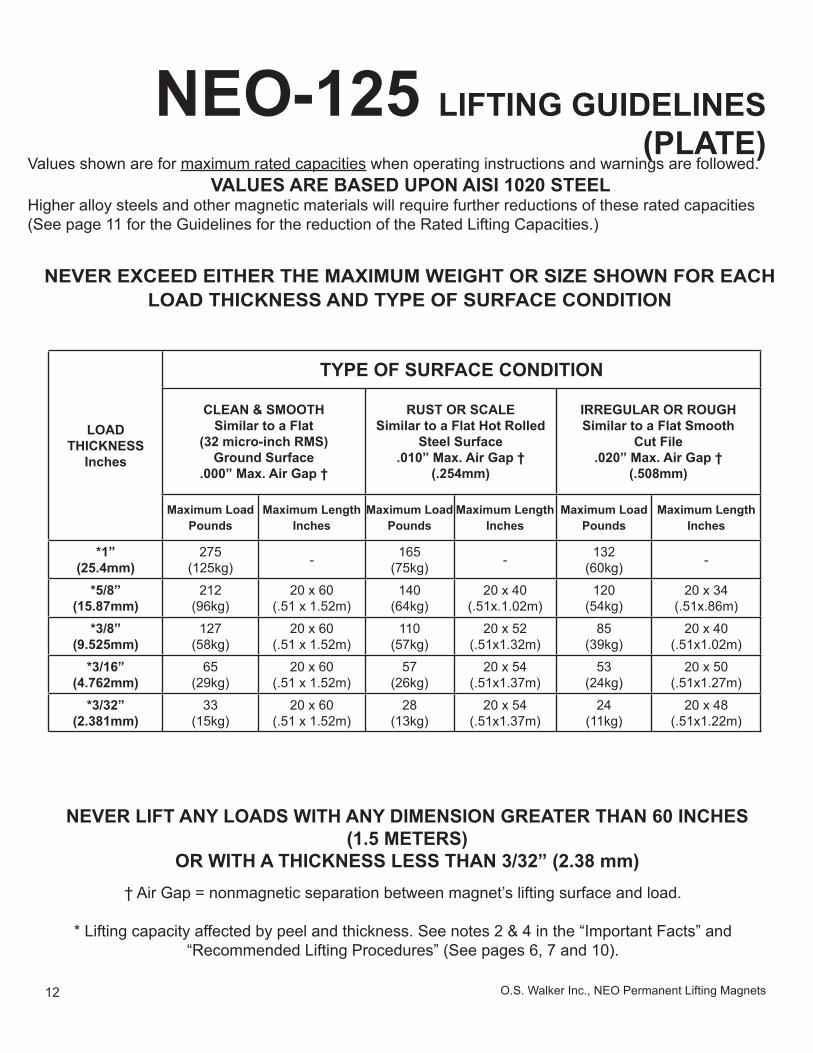
NEO-125 LIFTING GUIDELINES (PLATE)
Values shown are for maximum rated capacities when operating instructions and warnings are followed.VALUES ARE BASED UPON AISI 1020 STEEL
Higher alloy steels and other magnetic materials will require further reductions of these rated capacities (See page 11 for the Guidelines for the reduction of the Rated Lifting Capacities.)
NEVER EXCEED EITHER THE MAXIMUM WEIGHT OR SIZE SHOWN FOR EACH LOAD THICKNESS AND TYPE OF SURFACE CONDITION
LOADTHICKNESS
Inches
TYPE OF SURFACE CONDITION
CLEAN & SMOOTHSimilar to a Flat
(32 micro-inch RMS)Ground Surface
.000” Max. Air Gap †
RUST OR SCALESimilar to a Flat Hot Rolled
Steel Surface.010” Max. Air Gap †
(.254mm)
IRREGULAR OR ROUGHSimilar to a Flat Smooth
Cut File.020” Max. Air Gap †
(.508mm)
Maximum LoadPounds
Maximum Length Inches
Maximum LoadPounds
Maximum Length Inches
Maximum LoadPounds
Maximum Length Inches
*1”(25.4mm)
275(125kg) - 165
(75kg) - 132(60kg) -
*5/8”(15.87mm)
212(96kg)
20 x 60(.51 x 1.52m)
140(64kg)
20 x 40(.51x.1.02m)
120(54kg)
20 x 34(.51x.86m)
*3/8”(9.525mm)
127(58kg)
20 x 60(.51 x 1.52m)
110(57kg)
20 x 52(.51x1.32m)
85(39kg)
20 x 40(.51x1.02m)
*3/16”(4.762mm)
65(29kg)
20 x 60(.51 x 1.52m)
57(26kg)
20 x 54(.51x1.37m)
53(24kg)
20 x 50(.51x1.27m)
*3/32”(2.381mm)
33(15kg)
20 x 60(.51 x 1.52m)
28(13kg)
20 x 54(.51x1.37m)
24(11kg)
20 x 48(.51x1.22m)
NEVER LIFT ANY LOADS WITH ANY DIMENSION GREATER THAN 60 INCHES (1.5 METERS)
OR WITH A THICKNESS LESS THAN 3/32” (2.38 mm)† Air Gap = nonmagnetic separation between magnet’s lifting surface and load.
* Lifting capacity affected by peel and thickness. See notes 2 & 4 in the “Important Facts” and “Recommended Lifting Procedures” (See pages 6, 7 and 10).
13O.S. Walker Inc., NEO Permanent Lifting Magnets
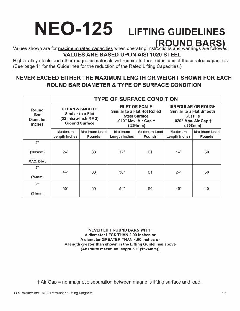
NEO-125 LIFTING GUIDELINES (ROUND BARS)
Values shown are for maximum rated capacities when operating instructions and warnings are followed.VALUES ARE BASED UPON AISI 1020 STEEL
Higher alloy steels and other magnetic materials will require further reductions of these rated capacities (See page 11 for the Guidelines for the reduction of the Rated Lifting Capacities.)
NEVER EXCEED EITHER THE MAXIMUM LENGTH OR WEIGHT SHOWN FOR EACH ROUND BAR DIAMETER & TYPE OF SURFACE CONDITION
RoundBar
DiameterInches
TYPE OF SURFACE CONDITIONCLEAN & SMOOTH
Similar to a Flat(32 micro-inch RMS)
Ground Surface
RUST OR SCALESimilar to a Flat Hot Rolled
Steel Surface.010” Max. Air Gap †
(.254mm)
IRREGULAR OR ROUGHSimilar to a Flat Smooth
Cut File.020” Max. Air Gap †
(.508mm)Maximum
Length InchesMaximum Load
PoundsMaximum
Length InchesMaximum Load
PoundsMaximum
Length InchesMaximum Load
Pounds4”
(102mm)
MAX. DIA..
24” 88 17” 61 14” 50
3”
(76mm)44” 88 30” 61 24” 50
2”
(51mm)60” 60 54” 50 45” 40
NEVER LIFT ROUND BARS WITH:A diameter LESS THAN 2.00 Inches or
A diameter GREATER THAN 4.00 Inches orA length greater than shown in the Lifting Guidelines above
(Absolute maximum length 60” (1524mm))
† Air Gap = nonmagnetic separation between magnet’s lifting surface and load.
14 O.S. Walker Inc., NEO Permanent Lifting Magnets
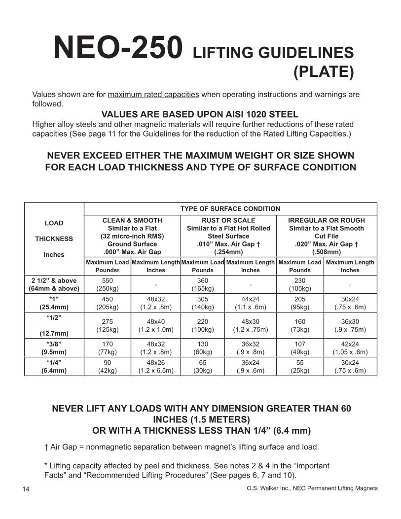
NEO-250 LIFTING GUIDELINES (PLATE)
NEVER EXCEED EITHER THE MAXIMUM WEIGHT OR SIZE SHOWN FOR EACH LOAD THICKNESS AND TYPE OF SURFACE CONDITION
LOAD
THICKNESS
Inches
TYPE OF SURFACE CONDITION
CLEAN & SMOOTHSimilar to a Flat
(32 micro-inch RMS)Ground Surface
.000” Max. Air Gap
RUST OR SCALESimilar to a Flat Hot Rolled
Steel Surface.010” Max. Air Gap †
(.254mm)
IRREGULAR OR ROUGHSimilar to a Flat Smooth
Cut File.020” Max. Air Gap †
(.508mm)Maximum Load
PoundssMaximum Length
InchesMaximum Load
PoundsMaximum Length
InchesMaximum Load
PoundsMaximum Length
Inches
2 1/2” & above (64mm & above)
550(250kg) - 360
(165kg) - 230(105kg) -
*1”(25.4mm)
450(205kg)
48x32(1.2 x .8m)
305(140kg)
44x24(1.1 x .6m)
205(95kg)
30x24(.75 x .6m)
*1/2”
(12.7mm)
275(125kg)
48x40(1.2 x 1.0m)
220(100kg)
48x30(1.2 x .75m)
160(73kg)
36x30(.9 x .75m)
*3/8”(9.5mm)
170(77kg)
48x32(1.2 x .8m)
130(60kg)
36x32(.9 x .8m)
107(49kg)
42x24(1.05 x .6m)
*1/4”(6.4mm)
90(42kg)
48x26(1.2 x 6.5m)
65(30kg)
36x24(.9 x .6m)
55(25kg)
30x24(.75 x .6m)
Values shown are for maximum rated capacities when operating instructions and warnings are followed.
VALUES ARE BASED UPON AISI 1020 STEELHigher alloy steels and other magnetic materials will require further reductions of these rated capacities (See page 11 for the Guidelines for the reduction of the Rated Lifting Capacities.)
NEVER LIFT ANY LOADS WITH ANY DIMENSION GREATER THAN 60 INCHES (1.5 METERS)
OR WITH A THICKNESS LESS THAN 1/4” (6.4 mm)† Air Gap = nonmagnetic separation between magnet’s lifting surface and load.
* Lifting capacity affected by peel and thickness. See notes 2 & 4 in the “Important Facts” and “Recommended Lifting Procedures” (See pages 6, 7 and 10).
15O.S. Walker Inc., NEO Permanent Lifting Magnets
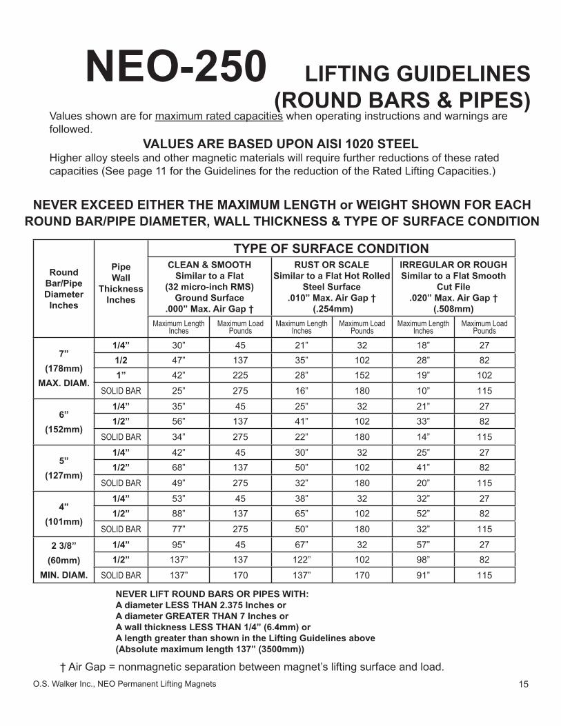
NEO-250 LIFTING GUIDELINES (ROUND BARS & PIPES)
Values shown are for maximum rated capacities when operating instructions and warnings are followed.
VALUES ARE BASED UPON AISI 1020 STEELHigher alloy steels and other magnetic materials will require further reductions of these rated capacities (See page 11 for the Guidelines for the reduction of the Rated Lifting Capacities.)
NEVER EXCEED EITHER THE MAXIMUM LENGTH or WEIGHT SHOWN FOR EACH ROUND BAR/PIPE DIAMETER, WALL THICKNESS & TYPE OF SURFACE CONDITION
RoundBar/PipeDiameterInches
PipeWall
ThicknessInches
TYPE OF SURFACE CONDITIONCLEAN & SMOOTH
Similar to a Flat(32 micro-inch RMS)
Ground Surface.000” Max. Air Gap †
RUST OR SCALESimilar to a Flat Hot Rolled
Steel Surface.010” Max. Air Gap †
(.254mm)
IRREGULAR OR ROUGHSimilar to a Flat Smooth
Cut File.020” Max. Air Gap †
(.508mm)Maximum Length
InchesMaximum Load
PoundsMaximum Length
InchesMaximum Load
PoundsMaximum Length
InchesMaximum Load
Pounds
7”(178mm)
MAX. DIAM.
1/4” 30” 45 21” 32 18” 271/2 47” 137 35” 102 28” 821” 42” 225 28” 152 19” 102
SOLID BAR 25” 275 16” 180 10” 115
6”(152mm)
1/4” 35” 45 25” 32 21” 271/2” 56” 137 41” 102 33” 82
SOLID BAR 34” 275 22” 180 14” 115
5”(127mm)
1/4” 42” 45 30” 32 25” 271/2” 68” 137 50” 102 41” 82
SOLID BAR 49” 275 32” 180 20” 115
4”(101mm)
1/4” 53” 45 38” 32 32” 271/2” 88” 137 65” 102 52” 82
SOLID BAR 77” 275 50” 180 32” 115
2 3/8”(60mm)
MIN. DIAM.
1/4” 95” 45 67” 32 57” 271/2” 137” 137 122” 102 98” 82
SOLID BAR 137” 170 137” 170 91” 115
NEVER LIFT ROUND BARS OR PIPES WITH:A diameter LESS THAN 2.375 Inches orA diameter GREATER THAN 7 Inches orA wall thickness LESS THAN 1/4” (6.4mm) orA length greater than shown in the Lifting Guidelines above(Absolute maximum length 137” (3500mm))
† Air Gap = nonmagnetic separation between magnet’s lifting surface and load.
16 O.S. Walker Inc., NEO Permanent Lifting Magnets
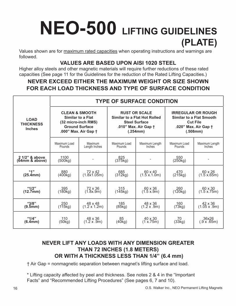
NEO-500 LIFTING GUIDELINES (PLATE)
Values shown are for maximum rated capacities when operating instructions and warnings are followed.
VALUES ARE BASED UPON AISI 1020 STEELHigher alloy steels and other magnetic materials will require further reductions of these rated capacities (See page 11 for the Guidelines for the reduction of the Rated Lifting Capacities.)
NEVER EXCEED EITHER THE MAXIMUM WEIGHT OR SIZE SHOWN FOR EACH LOAD THICKNESS AND TYPE OF SURFACE CONDITION
LOADTHICKNESS
Inches
TYPE OF SURFACE CONDITION
CLEAN & SMOOTHSimilar to a Flat
(32 micro-inch RMS)Ground Surface
.000” Max. Air Gap †
RUST OR SCALESimilar to a Flat Hot Rolled
Steel Surface.010” Max. Air Gap †
(.254mm)
IRREGULAR OR ROUGHSimilar to a Flat Smooth
Cut File.020” Max. Air Gap †
(.508mm)
Maximum LoadPounds
Maximum Length Inches
Maximum LoadPounds
Maximum LengthInches
Maximum LoadPounds
Maximum LengthInches
2 1/2” & above(64mm & above)
1100(500kg) - 825
(375kg) - 550(250kg) -
*1”(25.4mm)
880(400kg)
72 x 42(1.8x1.05m)
685(312kg)
60 x 40(1.5 x.1.0m)
470(215kg)
60 x 26(1.5 x.65m)
*1/2”(12.7mm)
395(180kg)
72 x 36(1.8x.9m)
315(145kg)
60 x 36(1.5 x.9m)
260(120kg)
60 x 30(1.5 x.75m)
*3/8”(9.5mm)
250(115kg)
48 x 48(1.2 x 1.2m)
185(85kg)
48 x 36(1.2 x .9m)
160(73kg)
42 x 36(1.05 x .9m)
*1/4”(6.4mm)
110(50kg)
48 x 36(1.2 x .9m)
85(40kg)
40 x 30(1 x.75m)
70(33kg)
36x26(.9 x .65m)
NEVER LIFT ANY LOADS WITH ANY DIMENSION GREATER THAN 72 INCHES (1.8 METERS)
OR WITH A THICKNESS LESS THAN 1/4” (6.4 mm)† Air Gap = nonmagnetic separation between magnet’s lifting surface and load.
* Lifting capacity affected by peel and thickness. See notes 2 & 4 in the “Important Facts” and “Recommended Lifting Procedures” (See pages 6, 7 and 10).
17O.S. Walker Inc., NEO Permanent Lifting Magnets
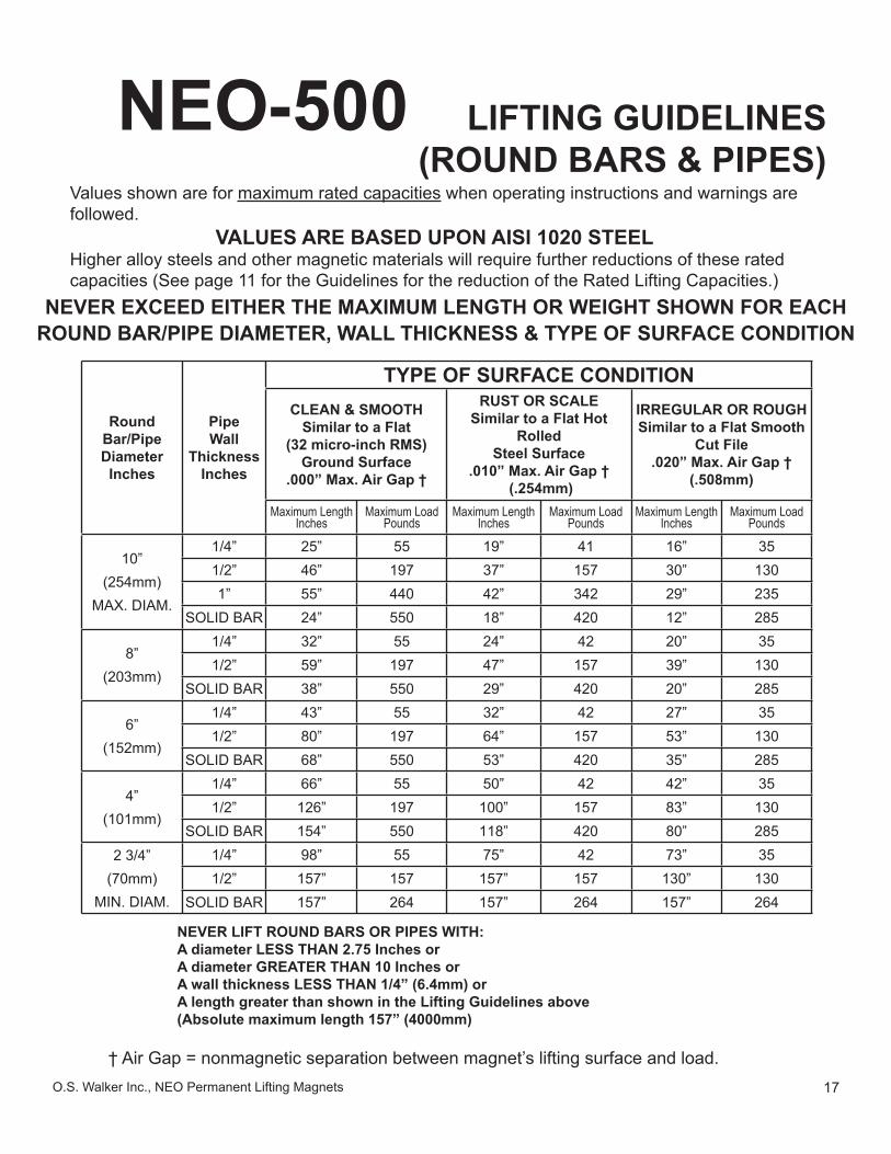
NEO-500 LIFTING GUIDELINES (ROUND BARS & PIPES)
Values shown are for maximum rated capacities when operating instructions and warnings are followed.
VALUES ARE BASED UPON AISI 1020 STEELHigher alloy steels and other magnetic materials will require further reductions of these rated capacities (See page 11 for the Guidelines for the reduction of the Rated Lifting Capacities.)
NEVER EXCEED EITHER THE MAXIMUM LENGTH OR WEIGHT SHOWN FOR EACH ROUND BAR/PIPE DIAMETER, WALL THICKNESS & TYPE OF SURFACE CONDITION
RoundBar/PipeDiameterInches
PipeWall
ThicknessInches
TYPE OF SURFACE CONDITIONCLEAN & SMOOTH
Similar to a Flat(32 micro-inch RMS)
Ground Surface.000” Max. Air Gap †
RUST OR SCALESimilar to a Flat Hot
RolledSteel Surface
.010” Max. Air Gap † (.254mm)
IRREGULAR OR ROUGHSimilar to a Flat Smooth
Cut File.020” Max. Air Gap †
(.508mm)
Maximum LengthInches
Maximum LoadPounds
Maximum LengthInches
Maximum LoadPounds
Maximum LengthInches
Maximum LoadPounds
10”(254mm)
MAX. DIAM.
1/4” 25” 55 19” 41 16” 351/2” 46” 197 37” 157 30” 1301” 55” 440 42” 342 29” 235
SOLID BAR 24” 550 18” 420 12” 285
8”(203mm)
1/4” 32” 55 24” 42 20” 351/2” 59” 197 47” 157 39” 130
SOLID BAR 38” 550 29” 420 20” 285
6”(152mm)
1/4” 43” 55 32” 42 27” 351/2” 80” 197 64” 157 53” 130
SOLID BAR 68” 550 53” 420 35” 285
4”(101mm)
1/4” 66” 55 50” 42 42” 351/2” 126” 197 100” 157 83” 130
SOLID BAR 154” 550 118” 420 80” 2852 3/4”
(70mm)MIN. DIAM.
1/4” 98” 55 75” 42 73” 351/2” 157” 157 157” 157 130” 130
SOLID BAR 157” 264 157” 264 157” 264
NEVER LIFT ROUND BARS OR PIPES WITH:A diameter LESS THAN 2.75 Inches orA diameter GREATER THAN 10 Inches orA wall thickness LESS THAN 1/4” (6.4mm) orA length greater than shown in the Lifting Guidelines above(Absolute maximum length 157” (4000mm)
† Air Gap = nonmagnetic separation between magnet’s lifting surface and load.
18 O.S. Walker Inc., NEO Permanent Lifting Magnets
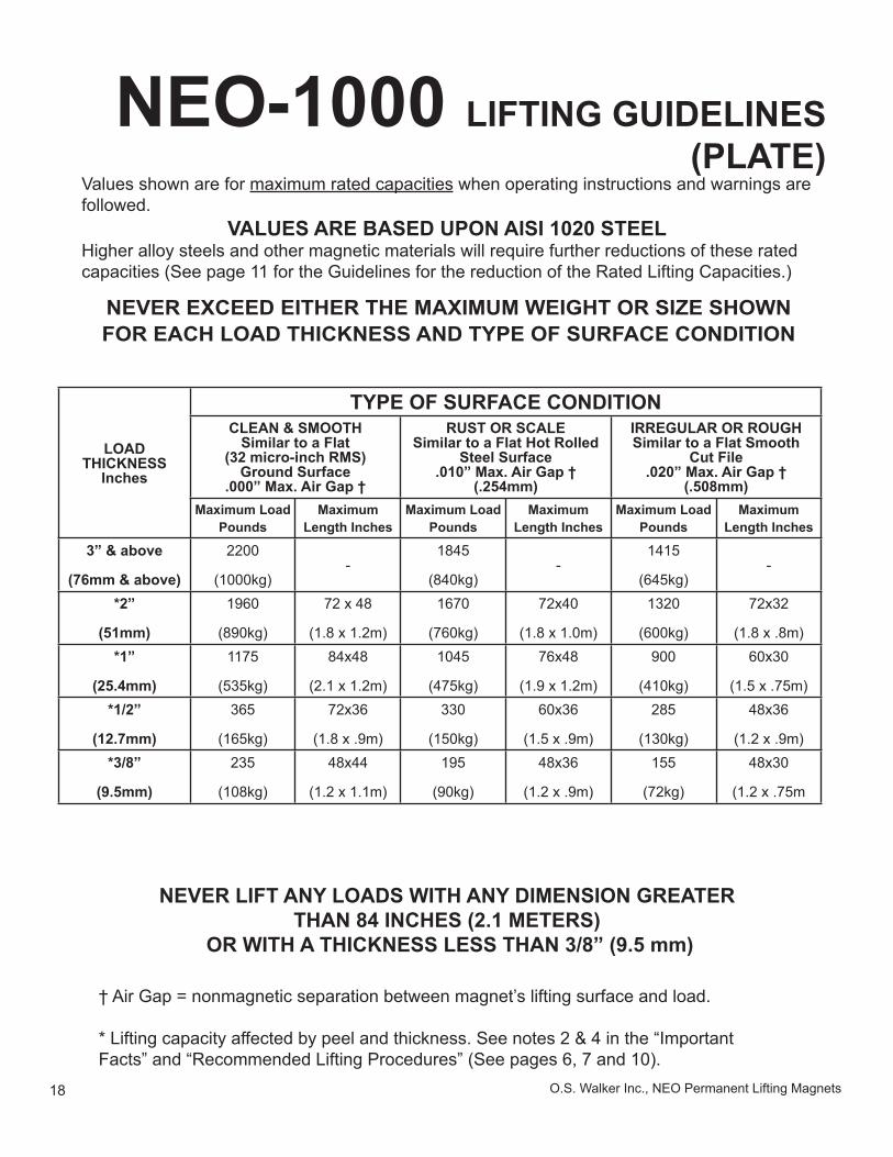
NEO-1000 LIFTING GUIDELINES (PLATE)
Values shown are for maximum rated capacities when operating instructions and warnings are followed.
VALUES ARE BASED UPON AISI 1020 STEELHigher alloy steels and other magnetic materials will require further reductions of these rated capacities (See page 11 for the Guidelines for the reduction of the Rated Lifting Capacities.)
NEVER EXCEED EITHER THE MAXIMUM WEIGHT OR SIZE SHOWN FOR EACH LOAD THICKNESS AND TYPE OF SURFACE CONDITION
LOADTHICKNESS
Inches
TYPE OF SURFACE CONDITIONCLEAN & SMOOTH
Similar to a Flat(32 micro-inch RMS)
Ground Surface.000” Max. Air Gap †
RUST OR SCALESimilar to a Flat Hot Rolled
Steel Surface.010” Max. Air Gap †
(.254mm)
IRREGULAR OR ROUGHSimilar to a Flat Smooth
Cut File.020” Max. Air Gap †
(.508mm)Maximum Load
PoundsMaximum
Length InchesMaximum Load
PoundsMaximum
Length InchesMaximum Load
PoundsMaximum
Length Inches
3” & above
(76mm & above)
2200
(1000kg)-
1845
(840kg)-
1415
(645kg)-
*2”
(51mm)
1960
(890kg)
72 x 48
(1.8 x 1.2m)
1670
(760kg)
72x40
(1.8 x 1.0m)
1320
(600kg)
72x32
(1.8 x .8m)*1”
(25.4mm)
1175
(535kg)
84x48
(2.1 x 1.2m)
1045
(475kg)
76x48
(1.9 x 1.2m)
900
(410kg)
60x30
(1.5 x .75m)*1/2”
(12.7mm)
365
(165kg)
72x36
(1.8 x .9m)
330
(150kg)
60x36
(1.5 x .9m)
285
(130kg)
48x36
(1.2 x .9m)*3/8”
(9.5mm)
235
(108kg)
48x44
(1.2 x 1.1m)
195
(90kg)
48x36
(1.2 x .9m)
155
(72kg)
48x30
(1.2 x .75m
NEVER LIFT ANY LOADS WITH ANY DIMENSION GREATER THAN 84 INCHES (2.1 METERS)
OR WITH A THICKNESS LESS THAN 3/8” (9.5 mm)
† Air Gap = nonmagnetic separation between magnet’s lifting surface and load.
* Lifting capacity affected by peel and thickness. See notes 2 & 4 in the “Important Facts” and “Recommended Lifting Procedures” (See pages 6, 7 and 10).
19O.S. Walker Inc., NEO Permanent Lifting Magnets
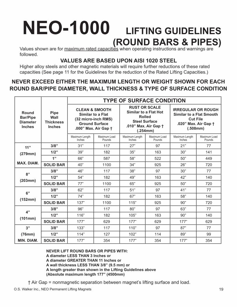
NEO-1000 LIFTING GUIDELINES (ROUND BARS & PIPES)
Values shown are for maximum rated capacities when operating instructions and warnings are followed.
VALUES ARE BASED UPON AISI 1020 STEELHigher alloy steels and other magnetic materials will require further reductions of these rated capacities (See page 11 for the Guidelines for the reduction of the Rated Lifting Capacities.)
NEVER EXCEED EITHER THE MAXIMUM LENGTH OR WEIGHT SHOWN FOR EACH ROUND BAR/PIPE DIAMETER, WALL THICKNESS & TYPE OF SURFACE CONDITION
RoundBar/PipeDiameterInches
PipeWall
ThicknessInches
TYPE OF SURFACE CONDITIONCLEAN & SMOOTH
Similar to a Flat(32 micro-inch RMS)
Ground Surface.000” Max. Air Gap †
RUST OR SCALESimilar to a Flat Hot
RolledSteel Surface
.010” Max. Air Gap † (.254mm)
IRREGULAR OR ROUGHSimilar to a Flat Smooth
Cut File.020” Max. Air Gap †
(.508mm)
Maximum LengthInches
Maximum LoadPounds
Maximum LengthInches
Maximum LoadPounds
Maximum LengthInches
Maximum LoadPounds
11”(279mm)
MAX. DIAM.
3/8” 31” 117 27” 97 21” 771/2” 39” 182 35” 163 30” 1411” 66” 587 58” 522 50” 449
SOLID BAR 40” 1100 34” 925 26” 720
8”(203mm)
3/8” 46” 117 38” 97 30” 771/2” 54” 182 49” 163 42” 140
SOLID BAR 77” 1100 65” 925 50” 720
6”(152mm)
3/8” 62” 117 51” 97 41” 771/2” 74” 182 67” 163 58” 140
SOLID BAR 137” 1100 115” 925 90” 720
4”(101mm)
3/8” 96” 117 80” 97 63” 771/2” 116” 182 105” 163 90” 140
SOLID BAR 177” 629 177” 629 177” 6293”
(76mm)MIN. DIAM.
3/8” 133” 117 110” 97 87” 771/2” 114” 127 102” 114 89” 99
SOLID BAR 177” 354 177” 354 177” 354
NEVER LIFT ROUND BARS OR PIPES WITH:A diameter LESS THAN 3 Inches orA diameter GREATER THAN 11 Inches orA wall thickness LESS THAN 3/8” (9.5 mm) orA length greater than shown in the Lifting Guidelines above(Absolute maximum length 177” (4500mm)
† Air Gap = nonmagnetic separation between magnet’s lifting surface and load.
20 O.S. Walker Inc., NEO Permanent Lifting Magnets
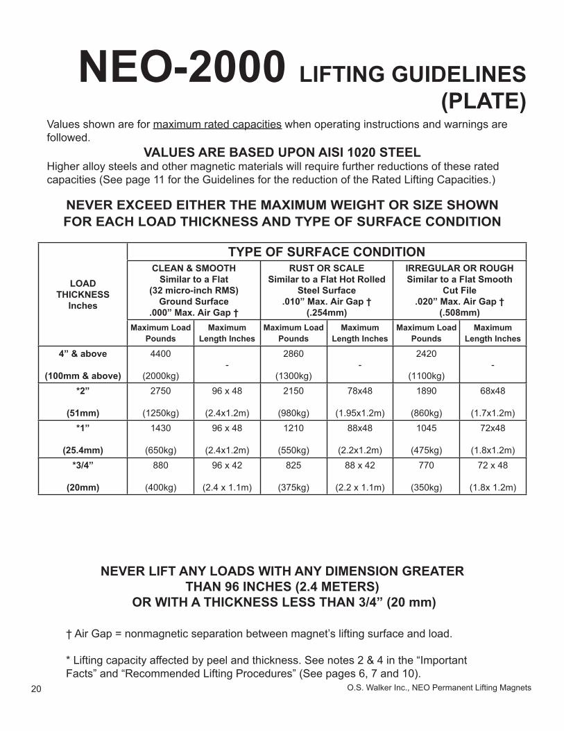
NEO-2000 LIFTING GUIDELINES (PLATE)
Values shown are for maximum rated capacities when operating instructions and warnings are followed.
VALUES ARE BASED UPON AISI 1020 STEELHigher alloy steels and other magnetic materials will require further reductions of these rated capacities (See page 11 for the Guidelines for the reduction of the Rated Lifting Capacities.)
NEVER EXCEED EITHER THE MAXIMUM WEIGHT OR SIZE SHOWN FOR EACH LOAD THICKNESS AND TYPE OF SURFACE CONDITION
LOADTHICKNESS
Inches
TYPE OF SURFACE CONDITIONCLEAN & SMOOTH
Similar to a Flat(32 micro-inch RMS)
Ground Surface.000” Max. Air Gap †
RUST OR SCALESimilar to a Flat Hot Rolled
Steel Surface.010” Max. Air Gap †
(.254mm)
IRREGULAR OR ROUGHSimilar to a Flat Smooth
Cut File.020” Max. Air Gap †
(.508mm)Maximum Load
PoundsMaximum
Length InchesMaximum Load
PoundsMaximum
Length InchesMaximum Load
PoundsMaximum
Length Inches
4” & above
(100mm & above)
4400
(2000kg)-
2860
(1300kg)-
2420
(1100kg)-
*2”
(51mm)
2750
(1250kg)
96 x 48
(2.4x1.2m)
2150
(980kg)
78x48
(1.95x1.2m)
1890
(860kg)
68x48
(1.7x1.2m)*1”
(25.4mm)
1430
(650kg)
96 x 48
(2.4x1.2m)
1210
(550kg)
88x48
(2.2x1.2m)
1045
(475kg)
72x48
(1.8x1.2m)*3/4”
(20mm)
880
(400kg)
96 x 42
(2.4 x 1.1m)
825
(375kg)
88 x 42
(2.2 x 1.1m)
770
(350kg)
72 x 48
(1.8x 1.2m)
NEVER LIFT ANY LOADS WITH ANY DIMENSION GREATER THAN 96 INCHES (2.4 METERS)
OR WITH A THICKNESS LESS THAN 3/4” (20 mm)
† Air Gap = nonmagnetic separation between magnet’s lifting surface and load.
* Lifting capacity affected by peel and thickness. See notes 2 & 4 in the “Important Facts” and “Recommended Lifting Procedures” (See pages 6, 7 and 10).
21O.S. Walker Inc., NEO Permanent Lifting Magnets
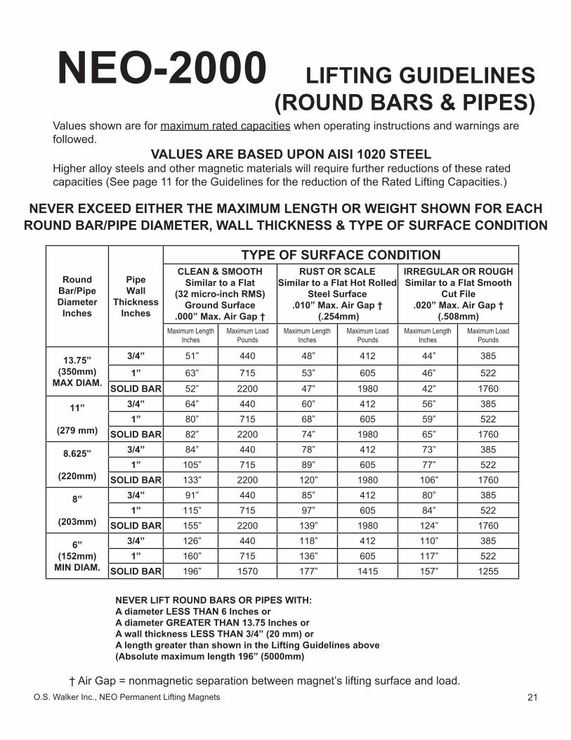
NEO-2000 LIFTING GUIDELINES (ROUND BARS & PIPES)
Values shown are for maximum rated capacities when operating instructions and warnings are followed.
VALUES ARE BASED UPON AISI 1020 STEELHigher alloy steels and other magnetic materials will require further reductions of these rated capacities (See page 11 for the Guidelines for the reduction of the Rated Lifting Capacities.)
NEVER EXCEED EITHER THE MAXIMUM LENGTH OR WEIGHT SHOWN FOR EACH ROUND BAR/PIPE DIAMETER, WALL THICKNESS & TYPE OF SURFACE CONDITION
RoundBar/PipeDiameterInches
PipeWall
ThicknessInches
TYPE OF SURFACE CONDITIONCLEAN & SMOOTH
Similar to a Flat(32 micro-inch RMS)
Ground Surface.000” Max. Air Gap †
RUST OR SCALESimilar to a Flat Hot Rolled
Steel Surface.010” Max. Air Gap †
(.254mm)
IRREGULAR OR ROUGHSimilar to a Flat Smooth
Cut File.020” Max. Air Gap †
(.508mm)Maximum Length
InchesMaximum Load
PoundsMaximum Length
InchesMaximum Load
PoundsMaximum Length
InchesMaximum Load
Pounds
13.75”(350mm)
MAX DIAM.
3/4” 51” 440 48” 412 44” 385
1” 63” 715 53” 605 46” 522
SOLID BAR 52” 2200 47” 1980 42” 1760
11”
(279 mm)
3/4” 64” 440 60” 412 56” 3851” 80” 715 68” 605 59” 522
SOLID BAR 82” 2200 74” 1980 65” 1760
8.625”
(220mm)
3/4” 84” 440 78” 412 73” 3851” 105” 715 89” 605 77” 522
SOLID BAR 133” 2200 120” 1980 106” 1760
8”
(203mm)
3/4” 91” 440 85” 412 80” 3851” 115” 715 97” 605 84” 522
SOLID BAR 155” 2200 139” 1980 124” 1760
6”(152mm)
MIN DIAM.
3/4” 126” 440 118” 412 110” 3851” 160” 715 136” 605 117” 522
SOLID BAR 196” 1570 177” 1415 157” 1255
NEVER LIFT ROUND BARS OR PIPES WITH:A diameter LESS THAN 6 Inches orA diameter GREATER THAN 13.75 Inches orA wall thickness LESS THAN 3/4” (20 mm) orA length greater than shown in the Lifting Guidelines above(Absolute maximum length 196” (5000mm)
† Air Gap = nonmagnetic separation between magnet’s lifting surface and load.
22 O.S. Walker Inc., NEO Permanent Lifting Magnets
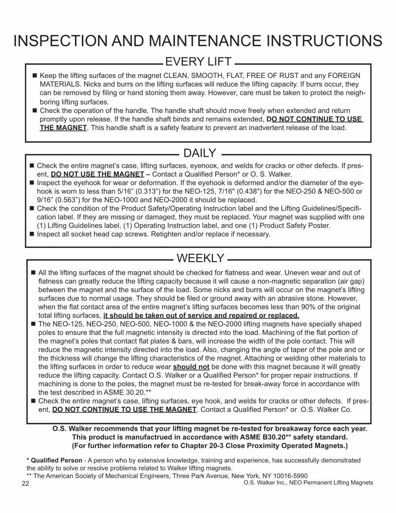
O.S. Walker recommends that your lifting magnet be re-tested for breakaway force each year.This product is manufactrued in accordance with ASME B30.20** safety standard.(For further information refer to Chapter 20-3 Close Proximity Operated Magnets.)
INSPECTION AND MAINTENANCE INSTRUCTIONS
* Qualifi ed Person - A person who by extensive knowledge, training and experience, has successfully demonstrated the ability to solve or resolve problems related to Walker lifting magnets.** The American Society of Mechanical Engineers, Three Park Avenue, New York, NY 10016-5990
Check the entire magnet’s case, lifting surfaces, eyehook, and welds for cracks or other defects. If pres-ent, DO NOT USE THE MAGNET – Contact a Qualifi ed Person* or O. S. Walker. Inspect the eyehook for wear or deformation. If the eyehook is deformed and/or the diameter of the eye-hook is worn to less than 5/16” (0.313”) for the NEO-125, 7/16" (0.438") for the NEO-250 & NEO-500 or 9/16” (0.563”) for the NEO-1000 and NEO-2000 it should be replaced. Check the condition of the Product Safety/Operating Instruction label and the Lifting Guidelines/Specifi -cation label. If they are missing or damaged, they must be replaced. Your magnet was supplied with one (1) Lifting Guidelines label, (1) Operating Instruction label, and one (1) Product Safety Poster. Inspect all socket head cap screws. Retighten and/or replace if necessary.
DAILY
Keep the lifting surfaces of the magnet CLEAN, SMOOTH, FLAT, FREE OF RUST and any FOREIGN MATERIALS. Nicks and burrs on the lifting surfaces will reduce the lifting capacity. If burrs occur, they can be removed by fi ling or hand stoning them away. However, care must be taken to protect the neigh-boring lifting surfaces. Check the operation of the handle. The handle shaft should move freely when extended and return promptly upon release. If the handle shaft binds and remains extended, DO NOT CONTINUE TO USE THE MAGNET. This handle shaft is a safety feature to prevent an inadvertent release of the load.
EVERY LIFT
WEEKLY All the lifting surfaces of the magnet should be checked for fl atness and wear. Uneven wear and out of fl atness can greatly reduce the lifting capacity because it will cause a non-magnetic separation (air gap) between the magnet and the surface of the load. Some nicks and burrs will occur on the magnet’s lifting surfaces due to normal usage. They should be fi led or ground away with an abrasive stone. However, when the fl at contact area of the entire magnet’s lifting surfaces becomes less than 90% of the original total lifting surfaces, it should be taken out of service and repaired or replaced. The NEO-125, NEO-250, NEO-500, NEO-1000 & the NEO-2000 lifting magnets have specially shaped poles to ensure that the full magnetic intensity is directed into the load. Machining of the fl at portion of the magnet’s poles that contact fl at plates & bars, will increase the width of the pole contact. This will reduce the magnetic intensity directed into the load. Also, changing the angle of taper of the pole and or the thickness will change the lifting characteristics of the magnet. Attaching or welding other materials to the lifting surfaces in order to reduce wear should not be done with this magnet because it will greatly reduce the lifting capacity. Contact O.S. Walker or a Qualifi ed Person* for proper repair instructions. If machining is done to the poles, the magnet must be re-tested for break-away force in accordance with the test described in ASME 30.20.** Check the entire magnet’s case, lifting surfaces, eye hook, and welds for cracks or other defects. If pres-ent, DO NOT CONTINUE TO USE THE MAGNET. Contact a Qualifi ed Person* or O.S. Walker Co.
23O.S. Walker Inc., NEO Permanent Lifting Magnets
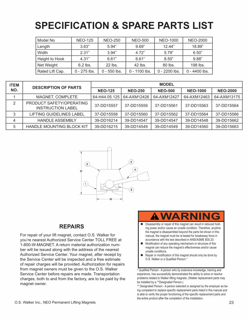
SPECIFICATION & SPARE PARTS LIST
Disassembly or repair of this magnet can result in reduced hold-ing power and/or cause an unsafe condition. Therefore, anytime the magnet is disassembled beyond the parts list shown in this manual, the magnet must be re-tested for breakaway force in accordance with the test described in ANSI/ASME B30.20. Modifi cation of any operating mechanism or structure of this
magnet can reduce the magnet’s effectiveness and/or cause unsafe conditions. Repair or modifi cation of this magnet should only be done by
O.S. Walker or a Qualifi ed Person.*
WARNING
* Qualifi ed Person - A person who by extensive knowledge, training and experience, has successfully demonstrated the ability to solve or resolve problems related to Walker lifting magnets. (Walker replacement parts may be installed by a **Designated Person.)** Designated Person - A person selected or assigned by the employer as be-ing competent to replace specifi c replacement parts listed in this manual and is able to verify the proper functioning of the specifi c replacement parts and the entire product after the completion of the installation.
Model No NEO-125 NEO-250 NEO-500 NEO-1000 NEO-2000Length 3.63” 5.94” 9.69” 12.44” 18.89”Width 2.31” 3.94” 4.72” 5.79” 6.50”Height to Hook 4.31” 6.61” 6.61” 8.50” 9.88”Net Weight 6.2 lbs. 22 lbs. 42 lbs. 80 lbs. 198 lbs.Rated Lift Cap. 0 - 275 lbs. 0 - 550 lbs. 0 - 1100 lbs. 0 - 2200 lbs. 0 - 4400 lbs.
ITEM NO. DESCRIPTION OF PARTS
MODELNEO-125 NEO-250 NEO-500 NEO-1000 NEO-2000
1 MAGNET, COMPLETE 64-H44.05.125 64-AXM12426 64-AXM12427 64-AXM12463 64-AXM131752 PRODUCT SAFETY/OPERATING
INSTRUCTION LABEL 37-DD15557 37-DD15559 37-DD15561 37-DD15563 37-DD15564
3 LIFTING GUIDELINES LABEL 37-DD15558 37-DD15560 37-DD15562 37-DD15564 37-DD155664 HANDLE ASSEMBLY 39-DD16214 39-DD14547 39-DD14547 39-DD14548 39-DD156625 HANDLE MOUNTING BLOCK KIT 39-DD16215 39-DD14549 39-DD14549 39-DD14560 39-DD15663
REPAIRSFor repair of your lift magnet, contact O.S. Walker for you’re nearest Authorized Service Center TOLL FREE at 1-800-W-MAGNET. A return material authorization num-ber will be issued along with the address of the nearest Authorized Service Center. Your magnet, after receipt by the Service Center will be inspected and a free estimate of repair charges will be provided. Authorization for repairs from magnet owners must be given to the O.S. Walker Service Center before repairs are made. Transportation charges, both to and from the factory, are to be paid by the magnet owner.
24 O.S. Walker Inc., NEO Permanent Lifting Magnets
Never use a damaged or improperly functioning device!
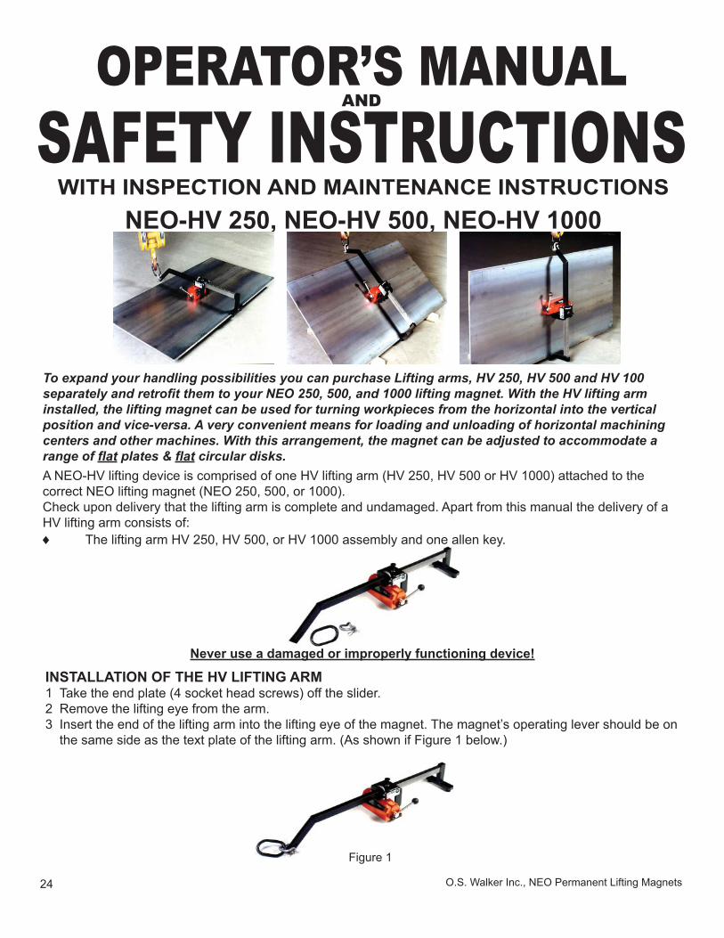
WITH INSPECTION AND MAINTENANCE INSTRUCTIONSNEO-HV 250, NEO-HV 500, NEO-HV 1000
OPERATOR’S MANUALAND
SAFETY INSTRUCTIONS
INSTALLATION OF THE HV LIFTING ARM1 Take the end plate (4 socket head screws) off the slider.2 Remove the lifting eye from the arm.3 Insert the end of the lifting arm into the lifting eye of the magnet. The magnet’s operating lever should be on
the same side as the text plate of the lifting arm. (As shown if Figure 1 below.)
To expand your handling possibilities you can purchase Lifting arms, HV 250, HV 500 and HV 100 separately and retrofi t them to your NEO 250, 500, and 1000 lifting magnet. With the HV lifting arm installed, the lifting magnet can be used for turning workpieces from the horizontal into the vertical position and vice-versa. A very convenient means for loading and unloading of horizontal machining centers and other machines. With this arrangement, the magnet can be adjusted to accommodate a range of fl at plates & fl at circular disks.A NEO-HV lifting device is comprised of one HV lifting arm (HV 250, HV 500 or HV 1000) attached to the correct NEO lifting magnet (NEO 250, 500, or 1000).Check upon delivery that the lifting arm is complete and undamaged. Apart from this manual the delivery of a HV lifting arm consists of:♦ The lifting arm HV 250, HV 500, or HV 1000 assembly and one allen key.
Figure 1
25O.S. Walker Inc., NEO Permanent Lifting Magnets
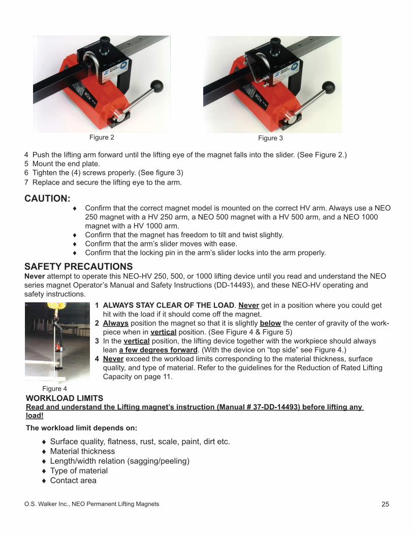
4 Push the lifting arm forward until the lifting eye of the magnet falls into the slider. (See Figure 2.)5 Mount the end plate.6 Tighten the (4) screws properly. (See fi gure 3)7 Replace and secure the lifting eye to the arm.
Figure 2
CAUTION:♦ Confi rm that the correct magnet model is mounted on the correct HV arm. Always use a NEO
250 magnet with a HV 250 arm, a NEO 500 magnet with a HV 500 arm, and a NEO 1000 magnet with a HV 1000 arm.
♦ Confi rm that the magnet has freedom to tilt and twist slightly.♦ Confi rm that the arm’s slider moves with ease.♦ Confi rm that the locking pin in the arm’s slider locks into the arm properly.
SAFETY PRECAUTIONSNever attempt to operate this NEO-HV 250, 500, or 1000 lifting device until you read and understand the NEO series magnet Operator’s Manual and Safety Instructions (DD-14493), and these NEO-HV operating and safety instructions.
1 ALWAYS STAY CLEAR OF THE LOAD. Never get in a position where you could get hit with the load if it should come off the magnet.
2 Always position the magnet so that it is slightly below the center of gravity of the work-piece when in vertical position. (See Figure 4 & Figure 5)
3 In the vertical position, the lifting device together with the workpiece should always lean a few degrees forward. (With the device on “top side” see Figure 4.)
4 Never exceed the workload limits corresponding to the material thickness, surface quality, and type of material. Refer to the guidelines for the Reduction of Rated Lifting Capacity on page 11.
Figure 4WORKLOAD LIMITSRead and understand the Lifting magnet’s instruction (Manual # 37-DD-14493) before lifting any load!The workload limit depends on:
♦ Surface quality, fl atness, rust, scale, paint, dirt etc.♦ Material thickness♦ Length/width relation (sagging/peeling)♦ Type of material♦ Contact area
Figure 3
26 O.S. Walker Inc., NEO Permanent Lifting Magnets
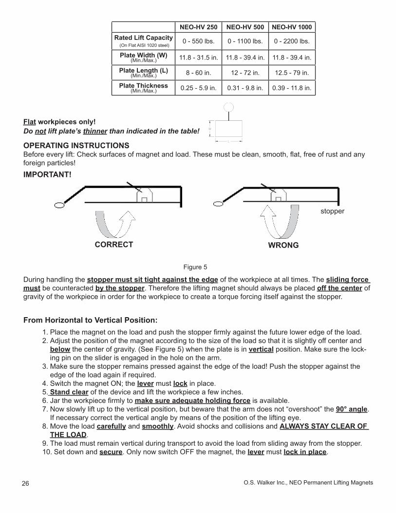
Flat workpieces only!Do not lift plate’s thinner than indicated in the table!
OPERATING INSTRUCTIONSBefore every lift: Check surfaces of magnet and load. These must be clean, smooth, fl at, free of rust and any foreign particles!IMPORTANT!
During handling the stopper must sit tight against the edge of the workpiece at all times. The sliding force must be counteracted by the stopper. Therefore the lifting magnet should always be placed off the center of gravity of the workpiece in order for the workpiece to create a torque forcing itself against the stopper.
1. Place the magnet on the load and push the stopper fi rmly against the future lower edge of the load.2. Adjust the position of the magnet according to the size of the load so that it is slightly off center and
below the center of gravity. (See Figure 5) when the plate is in vertical position. Make sure the lock-ing pin on the slider is engaged in the hole on the arm.
3. Make sure the stopper remains pressed against the edge of the load! Push the stopper against the edge of the load again if required.
4. Switch the magnet ON; the lever must lock in place. 5. Stand clear of the device and lift the workpiece a few inches.6. Jar the workpiece fi rmly to make sure adequate holding force is available.7. Now slowly lift up to the vertical position, but beware that the arm does not “overshoot” the 90° angle.
If necessary correct the vertical angle by means of the position of the lifting eye.8. Move the load carefully and smoothly. Avoid shocks and collisions and ALWAYS STAY CLEAR OF
THE LOAD.9. The load must remain vertical during transport to avoid the load from sliding away from the stopper.10. Set down and secure. Only now switch OFF the magnet, the lever must lock in place.
From Horizontal to Vertical Position:
WRONGCORRECT
stopperstopper
Figure 5
NEO-HV 250 NEO-HV 500 NEO-HV 1000Rated Lift Capacity
(On Flat AISI 1020 steel)0 - 550 lbs. 0 - 1100 lbs. 0 - 2200 lbs.
Plate Width (W)(Min./Max.) 11.8 - 31.5 in. 11.8 - 39.4 in. 11.8 - 39.4 in.
Plate Length (L)(Min./Max.) 8 - 60 in. 12 - 72 in. 12.5 - 79 in.
Plate Thickness(Min./Max.) 0.25 - 5.9 in. 0.31 - 9.8 in. 0.39 - 11.8 in.

27O.S. Walker Inc., NEO Permanent Lifting Magnets
HV INSPECTION AND MAINTENANCEAlso see Inspection and Maintenance Instructions for the magnet on page 22.
Check lifting arm for deformations, cracks, and wear. Replace the lifting eye if worn for more than 10%. Grease slider and locking pin. Replace a damaged and/or illegible text plate.
WEEKLY
ANNUALLY Have the device inspected and tested by O. S. Walker or by a qualifi ed person.
Check condition and function of slider and locking pin.
DAILY
1 Push the device against the workpiece surface on the centerline and adjust the position of the magnet according to the size of the load so that it is slightly off center and below the center of gravity. (See Figure 5) Make sure the locking pin on the slider is engaged in the slot.
2 Push the stopper fi rmly against the lower edge of the workpiece.3 Switch the magnet ON; the lever must lock in place.4 Detach, stand clear, and lift the workpiece. Check the vertical angle. If required adjust the
position of the lifting eye so that the load leans forward slightly.5 Jar the load to make sure adequate holding is available.6 Move the workpiece carefully and smoothly. Avoid shocks and collisions and ALWAYS
STAY CLEAR OF THE LOAD.7 The load must remain vertical during transport to avoid the load from sliding away from the
stopper.8 Lower the workpiece slowly to horizontal position and make sure that the lifting arm does
not slide away uncontrollably. Secure the load.9 Only now switch OFF the magnet, the lever must lock in place.
From Vertical to Horizontal Position:
28 O.S. Walker Inc., NEO Permanent Lifting Magnets
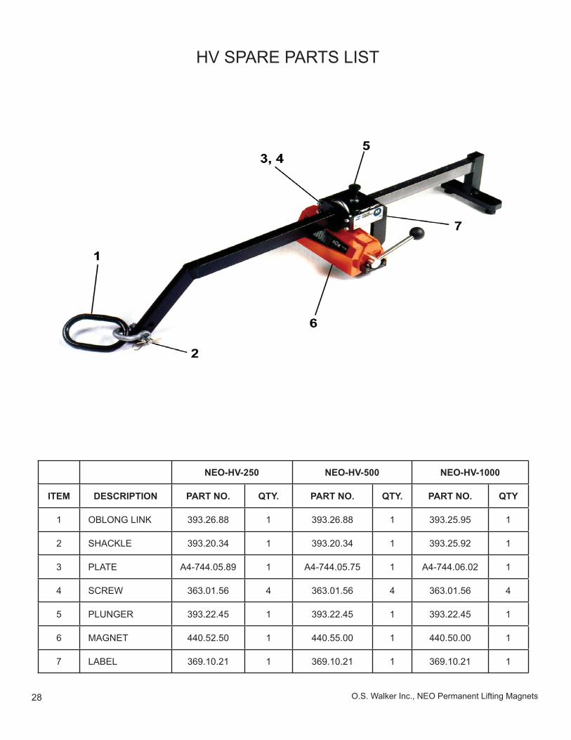
HV SPARE PARTS LIST
NEO-HV-250 NEO-HV-500 NEO-HV-1000
ITEM DESCRIPTION PART NO. QTY. PART NO. QTY. PART NO. QTY
1 OBLONG LINK 393.26.88 1 393.26.88 1 393.25.95 1
2 SHACKLE 393.20.34 1 393.20.34 1 393.25.92 1
3 PLATE A4-744.05.89 1 A4-744.05.75 1 A4-744.06.02 1
4 SCREW 363.01.56 4 363.01.56 4 363.01.56 4
5 PLUNGER 393.22.45 1 393.22.45 1 393.22.45 1
6 MAGNET 440.52.50 1 440.55.00 1 440.50.00 1
7 LABEL 369.10.21 1 369.10.21 1 369.10.21 1
37-DD14493 Rev. G July 14, 2009O.S. Walker Inc., NEO Permanent Lifting Magnets
FOR FAST RESPONSE, CALL 1-800-W-MAGNETO.S. WALKERRockdale Street, Worcester, MA 01606(508) 853-3232 FAX (508) 852-86491-800-W-MAGNET3508 Glenridge Drive, Chino Hills, CA 91709(909) 597-4785 FAX (909) 597-0581901 Arvin Avenue, Stoney Creek, Ontario, L8E5N9 Canada(905)643-3338In Canada: 1-800-267-4678 FAX (905) 643-6111www.walkermagnet.come-mail: [email protected]
WALKER
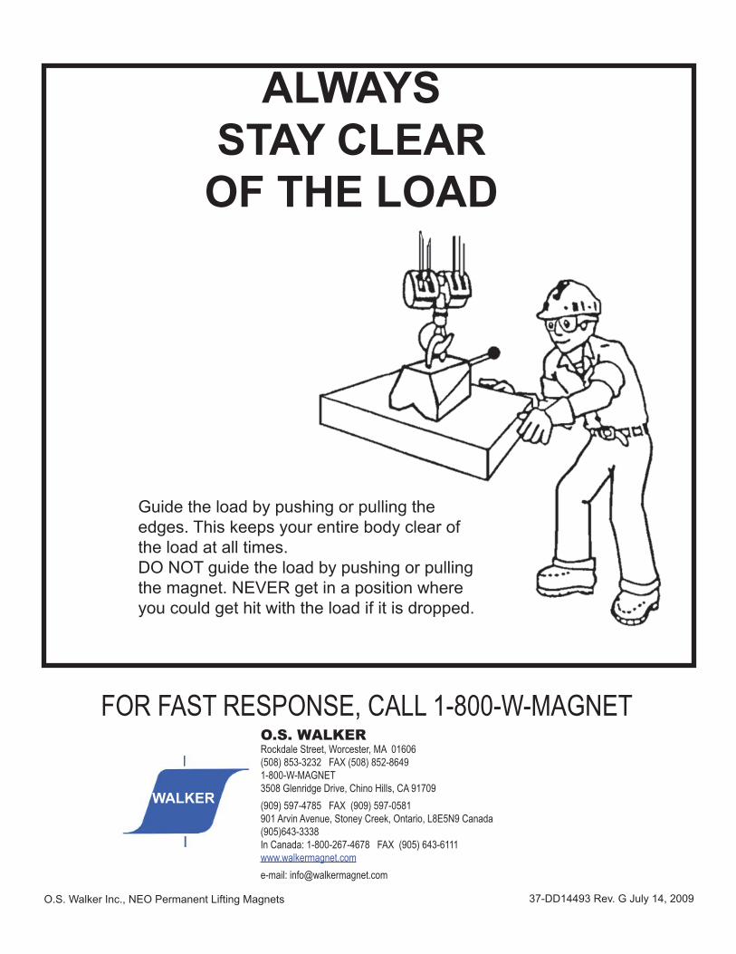
ALWAYSSTAY CLEAR
OF THE LOAD
Guide the load by pushing or pulling the edges. This keeps your entire body clear of the load at all times.DO NOT guide the load by pushing or pulling the magnet. NEVER get in a position where you could get hit with the load if it is dropped.