Ijnulauñ 1873 : Wi-Fi E-Journal „ %ffl5ðnnU Wi-Fi Wi Fi Wi ...
Upload
nguyentramCategory
view
217download
0
white paper
Clear Voice OverWi-Fi in the EnterpriseDELIVERING HIGH-QUALITY VOIP OVER SMART ENTERPRISE WIRELESS LANS.
Executive summaryWireless LANs (WLANs) are becoming pervasive in the enterprise. Businesses are turning to WLANs to give employees immediate access to business applications and communication tools. By adding voice to their to their wireless networks, businesses can improve collaboration and responsiveness, and save money by being more efficient. The increasing use of Voice over Wi-Fi (VoFi) phones and dual-mode phones offering services like Unlicensed Mobile Access (UMA), offer new opportunities to increase productivity in the workplace.
However, Voice over Wi-Fi places some unique requirements on the WLAN that are vastly different from data. The effect of signal degradation due to interference and obstructions in an enterprise can play havoc with voice, whilst not affecting data traffic quite so much. Transmission paths must be chosen between the access point (AP) and voice client that maximizes the signal in the presence of background noise and interference.
Quality of service must be maintained, so that voice packets get priority over data. The system must allow for the voice client to conserve power, so that battery life is high. As voice clients roam from AP to AP, resulting in re-association and re- authentication, the system must ensure a high level of security, while roaming with the least amount of delay so as to not affect voice quality or cause dropped calls. In addition, roaming needs to work in a Layer 2 or Layer 3 environment, allowing the enterprise to choose the right architecture, without impacting voice quality.
The following sections provide further details on the issues and challenges facing Voice over Wi-Fi technology, and how to overcome these challenges.
By maximizing transmit signal strength and receiver sensitivity, voice handsets can send the same information in shorter timeframes, using less power. This can be accomplished by using Smart Wi-Fi antennas resulting in increased signal towards each voice handset, reducing retransmissions, extending battery life, and improving user satisfaction.
Clear Voice OverWi-Fi in the EnterpriseDELIVERING HIGH-QUALITY VOIP OVER SMART ENTERPRISE WIRELESS LANS.
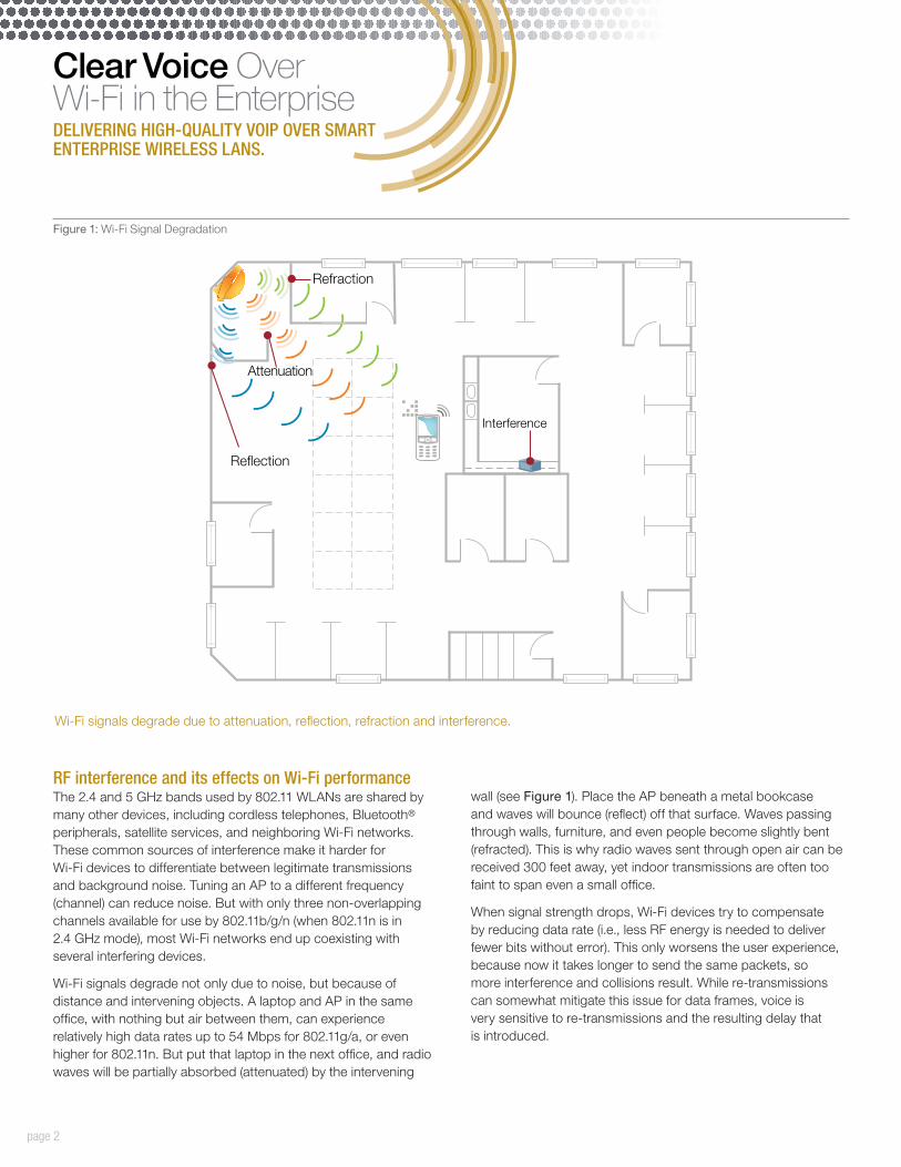
wall (see Figure 1). Place the AP beneath a metal bookcase and waves will bounce (reflect) off that surface. Waves passing through walls, furniture, and even people become slightly bent (refracted). This is why radio waves sent through open air can be received 300 feet away, yet indoor transmissions are often too faint to span even a small office.
When signal strength drops, Wi-Fi devices try to compensate by reducing data rate (i.e., less RF energy is needed to deliver fewer bits without error). This only worsens the user experience, because now it takes longer to send the same packets, so more interference and collisions result. While re-transmissions can somewhat mitigate this issue for data frames, voice is very sensitive to re-transmissions and the resulting delay that is introduced.
RF interference and its effects on Wi-Fi performanceThe 2.4 and 5 GHz bands used by 802.11 WLANs are shared by many other devices, including cordless telephones, Bluetooth® peripherals, satellite services, and neighboring Wi-Fi networks. These common sources of interference make it harder for Wi-Fi devices to differentiate between legitimate transmissions and background noise. Tuning an AP to a different frequency (channel) can reduce noise. But with only three non-overlapping channels available for use by 802.11b/g/n (when 802.11n is in 2.4 GHz mode), most Wi-Fi networks end up coexisting with several interfering devices.
Wi-Fi signals degrade not only due to noise, but because of distance and intervening objects. A laptop and AP in the same office, with nothing but air between them, can experience relatively high data rates up to 54 Mbps for 802.11g/a, or even higher for 802.11n. But put that laptop in the next office, and radio waves will be partially absorbed (attenuated) by the intervening
page 2
Refraction
Re�ection
Interference
Attenuation
Figure 1: Wi-Fi Signal Degradation
Wi-Fi signals degrade due to attenuation, reflection, refraction and interference.

Clear Voice OverWi-Fi in the EnterpriseDELIVERING HIGH-QUALITY VOIP OVER SMART ENTERPRISE WIRELESS LANS.
Multipath and 802.11nWi-Fi networks are also impacted by RF phenomena like hidden nodes and multipath. Multipath occurs because radio waves are reflected to some degree by every object encountered between transmitter and receiver, especially concrete or metal surfaces (e.g., glass, elevator shafts, doors). Multiple reflections of the same signal may reach the receiver, where they increase, decrease, null, or corrupt the primary signal. This common phenomenon creates coverage holes and pockets where signals
severely degrade. Avoiding multipath is difficult, even if conditions remained constant. However, the RF environment changes continuously, with microwave ovens that generate noise bursts, people in motion that alter the way radio waves propagate, and constant changes throughout the enterprise. Even small environ-mental changes can have huge impact on performance.
page 3
Interference
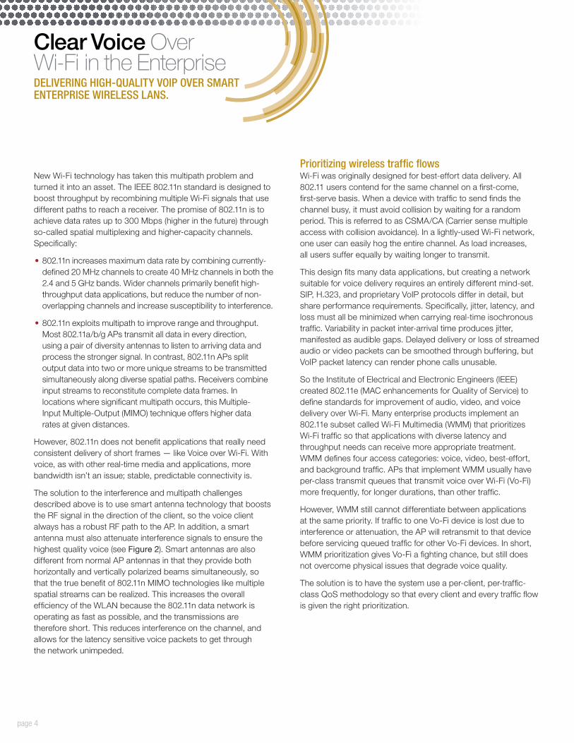
Figure 2: Better signal strength received at clients
Smart Wi-Fi provides dynamic path selection per device, directing Wi-Fi signals resulting in better signal strength at the client
Clear Voice OverWi-Fi in the EnterpriseDELIVERING HIGH-QUALITY VOIP OVER SMART ENTERPRISE WIRELESS LANS.
New Wi-Fi technology has taken this multipath problem and turned it into an asset. The IEEE 802.11n standard is designed to boost throughput by recombining multiple Wi-Fi signals that use different paths to reach a receiver. The promise of 802.11n is to achieve data rates up to 300 Mbps (higher in the future) through so-called spatial multiplexing and higher-capacity channels. Specifically:
•802.11n increases maximum data rate by combining currently-defined 20 MHz channels to create 40 MHz channels in both the 2.4 and 5 GHz bands. Wider channels primarily benefit high-throughput data applications, but reduce the number of non-overlapping channels and increase susceptibility to interference.
•802.11n exploits multipath to improve range and throughput. Most 802.11a/b/g APs transmit all data in every direction, using a pair of diversity antennas to listen to arriving data and process the stronger signal. In contrast, 802.11n APs split output data into two or more unique streams to be transmitted simultaneously along diverse spatial paths. Receivers combine input streams to reconstitute complete data frames. In locations where significant multipath occurs, this Multiple- Input Multiple-Output (MIMO) technique offers higher data rates at given distances.
However, 802.11n does not benefit applications that really need consistent delivery of short frames — like Voice over Wi-Fi. With voice, as with other real-time media and applications, more bandwidth isn’t an issue; stable, predictable connectivity is.
The solution to the interference and multipath challenges described above is to use smart antenna technology that boosts the RF signal in the direction of the client, so the voice client always has a robust RF path to the AP. In addition, a smart antenna must also attenuate interference signals to ensure the highest quality voice (see Figure 2). Smart antennas are also different from normal AP antennas in that they provide both horizontally and vertically polarized beams simultaneously, so that the true benefit of 802.11n MIMO technologies like multiple spatial streams can be realized. This increases the overall efficiency of the WLAN because the 802.11n data network is operating as fast as possible, and the transmissions are therefore short. This reduces interference on the channel, and allows for the latency sensitive voice packets to get through the network unimpeded.
Prioritizing wireless traffic flowsWi-Fi was originally designed for best-effort data delivery. All 802.11 users contend for the same channel on a first-come, first-serve basis. When a device with traffic to send finds the channel busy, it must avoid collision by waiting for a random period. This is referred to as CSMA/CA (Carrier sense multiple access with collision avoidance). In a lightly-used Wi-Fi network, one user can easily hog the entire channel. As load increases, all users suffer equally by waiting longer to transmit.
This design fits many data applications, but creating a network suitable for voice delivery requires an entirely different mind-set. SIP, H.323, and proprietary VoIP protocols differ in detail, but share performance requirements. Specifically, jitter, latency, and loss must all be minimized when carrying real-time isochronous traffic. Variability in packet inter-arrival time produces jitter, manifested as audible gaps. Delayed delivery or loss of streamed audio or video packets can be smoothed through buffering, but VoIP packet latency can render phone calls unusable.
So the Institute of Electrical and Electronic Engineers (IEEE) created 802.11e (MAC enhancements for Quality of Service) to define standards for improvement of audio, video, and voice delivery over Wi-Fi. Many enterprise products implement an 802.11e subset called Wi-Fi Multimedia (WMM) that prioritizes Wi-Fi traffic so that applications with diverse latency and throughput needs can receive more appropriate treatment. WMM defines four access categories: voice, video, best-effort, and background traffic. APs that implement WMM usually have per-class transmit queues that transmit voice over Wi-Fi (Vo-Fi) more frequently, for longer durations, than other traffic.
However, WMM still cannot differentiate between applications at the same priority. If traffic to one Vo-Fi device is lost due to interference or attenuation, the AP will retransmit to that device before servicing queued traffic for other Vo-Fi devices. In short, WMM prioritization gives Vo-Fi a fighting chance, but still does not overcome physical issues that degrade voice quality.
The solution is to have the system use a per-client, per-traffic-class QoS methodology so that every client and every traffic flow is given the right prioritization.
page 4
Clear Voice OverWi-Fi in the EnterpriseDELIVERING HIGH-QUALITY VOIP OVER SMART ENTERPRISE WIRELESS LANS.
that supports this standard to send buffered voice frames to it periodically, after which the voice client goes to sleep for a pre-determined time. This process repeats itself in a wake-sleep-wake-sleep endless loop that offers greatly improved battery life for the client.
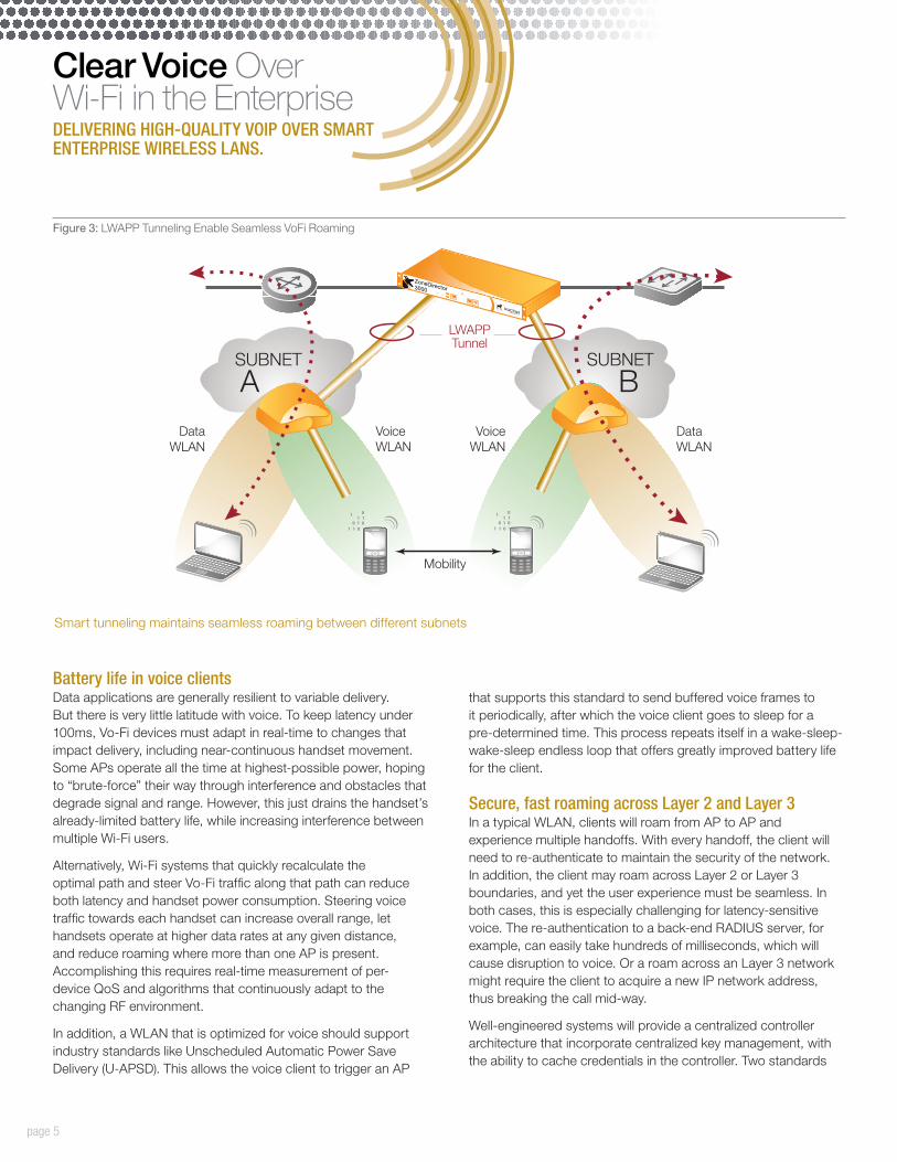
Secure, fast roaming across Layer 2 and Layer 3In a typical WLAN, clients will roam from AP to AP and experience multiple handoffs. With every handoff, the client will need to re-authenticate to maintain the security of the network. In addition, the client may roam across Layer 2 or Layer 3 boundaries, and yet the user experience must be seamless. In both cases, this is especially challenging for latency-sensitive voice. The re-authentication to a back-end RADIUS server, for example, can easily take hundreds of milliseconds, which will cause disruption to voice. Or a roam across an Layer 3 network might require the client to acquire a new IP network address, thus breaking the call mid-way.
Well-engineered systems will provide a centralized controller architecture that incorporate centralized key management, with the ability to cache credentials in the controller. Two standards
Battery life in voice clientsData applications are generally resilient to variable delivery. But there is very little latitude with voice. To keep latency under 100ms, Vo-Fi devices must adapt in real-time to changes that impact delivery, including near-continuous handset movement. Some APs operate all the time at highest-possible power, hoping to “brute-force” their way through interference and obstacles that degrade signal and range. However, this just drains the handset’s already-limited battery life, while increasing interference between multiple Wi-Fi users.
Alternatively, Wi-Fi systems that quickly recalculate the optimal path and steer Vo-Fi traffic along that path can reduce both latency and handset power consumption. Steering voice traffic towards each handset can increase overall range, let handsets operate at higher data rates at any given distance, and reduce roaming where more than one AP is present. Accomplishing this requires real-time measurement of per- device QoS and algorithms that continuously adapt to the changing RF environment.
In addition, a WLAN that is optimized for voice should support industry standards like Unscheduled Automatic Power Save Delivery (U-APSD). This allows the voice client to trigger an AP
page 5
VoiceWLAN
VoiceWLAN
LWAPPTunnel
Mobility
DataWLAN
DataWLAN
ZoneDirector3000
SUBNET
ASUBNET
B
Figure 3: LWAPP Tunneling Enable Seamless VoFi Roaming
Smart tunneling maintains seamless roaming between different subnets

Ruckus Wireless, Inc. 350 West Java Drive Sunnyvale, CA 94089 USA (650) 265-4200 Ph \ (408) 738-2065 Fx
www.ruckuswireless.com
Clear Voice OverWi-Fi in the EnterpriseDELIVERING HIGH-QUALITY VOIP OVER SMART ENTERPRISE WIRELESS LANS.
Copyright © 2014, Ruckus Wireless, Inc. All rights reserved. Ruckus Wireless and Ruckus Wireless design are registered in the U.S. Patent and Trademark Office. Ruckus Wireless, the Ruckus Wireless logo, BeamFlex, ZoneFlex, MediaFlex, FlexMaster, ZoneDirector, SpeedFlex, SmartCast, SmartCell, ChannelFly and Dynamic PSK are trademarks of Ruckus Wireless, Inc. in the United States and other countries. All other trademarks mentioned in this document or website are the property of their respective owners. 803-71263-001 rev 04
based techniques for this are Pairwise Master Key (PMK) Caching, and Opportunistic PMK Caching. When a client roams away and then back to an AP, PMK caching allows the client to use previously cached credentials on the server, instead of forcing the client to go back to the back-end RADIUS server. In Opportunistic PMK Caching, the cached credentials in the switch are re-distributed to all the APs in the vicinity so that if the client associates with one of these APs, it does not have to do the full back-end authentication.
To solve the Layer 3 roaming problem, Smart WLAN systems use some form of routable tunneling protocol. When a client roams across an Layer 3 boundary, the voice traffic is tunneled from the handset back to the original subnet, thus preserving its IP address. The voice session is maintained with no loss as the user roams across Layer 3 boundaries.
Succeeding at enterprise-grade voice deliveryUltimately, Voice over Wi-Fi faces a myriad of technical challenges that make performance hard to predict, much less control. When it comes to voice delivery, consistency and reliability are critical. Improvements like MIMO and 802.11n will not make the situation any better for voice — in fact, higher-throughput data will increases airwave competition and interference.
The key technologies that will help us deliver on the promise of VoFi are smart antennas to minimize interference and increase the overall efficiency of the network. The efficiencies gained by smart antennas will also help preserve battery life, by minimizing interference, retries, and slow transfers, thus allowing clients to sleep for longer. Enterprises are looking for reliable wireless networks that can deliver predictable Quality of Service (QoS) — supporting not only WMM, but also supporting per-client prioritization. In addition, it will take a centralized architecture with key caching capabilities that delivers fast, secure roaming across Layer 2 or 3 boundaries.
TABLE 1
NOT ALL WI-FI CREATED EQUAL
Conventional Wi-Fi Smart Wi-Fi
Best effort VoIP over Wi-Fi Toll-grade voice over Wi-Fi
Unmanaged spectrumVisibility into RF spectrum, spectrum management, interference avoidance
50m Vo-Fi radius 100m+ Vo-Fi radius
No control over signal path selection
Adaptive signal path selection
Single or multiple omni directional antenna subject to interference
Automatic interference mitigation and avoidance through directional, high-gain antenna subsystem
Vertically polarized antennaSimultaneous use of vertically and horizontally polarized antenna pattern for best 802.11n performance
Standards based WMM QoS. No per client QoS.
Standards based WMM, plus per client, per traffic-flow based QoS
Call loss on Layer 3 roamTunneling protocol to preserve IP address and voice session
Interference and retries drain battery life
Smart antennas and U-APSD support preserve battery life


![OdakyuAndroid t Google play] Wi-Fi Android ios t App Store] Wi-Fi [App Store] [iPhone Profile) Wi-Fi # —E Odakyu Odakyu Free Wi-Fi Android [Google play] WI-Fi Android [App Wi-Fi](https://static.fdocuments.us/doc/165x107/5fcc31f69b77e950d81a9828/android-t-google-play-wi-fi-android-ios-t-app-store-wi-fi-app-store-iphone.jpg)