Wheelchair Guidelines Development Process. Wheelchair or Chair with wheels?
WISDOM: Wheelchair Inertial Sensors for
Displacement and Orientation Monitoring
Submitted to: Measurement Science and Technology ‡
J Pansiot, Z Zhang, B Lo, and GZ Yang
The Hamlyn Centre, Institute of Global Health InnovationImperial College London, UK
E-mail: [email protected]
‡ This is an author-created, un-copyedited version of an article accepted for publication in MeasurementScience and Technology. IOP Publishing Ltd is not responsible for any errors or omissions in this versionof the manuscript or any version derived from it. The definitive publisher-authenticated version isavailable online at: http://stacks.iop.org/MST/22/105801 .
Wheelchair Displacement and Orientation Monitoring 2
Abstract. Improved wheelchair design in recent years has significantly increased themobility of people with disabilities, which has also enhanced the competitive advantageof wheelchair sports. For the latter, detailed assessment of biomechanical factorsinfluencing individual performance and team tactics requires real-time wireless sensingand data modelling. In this paper, we propose the use of a miniaturised wireless wheel-mounted inertial sensor for wheelchair motion monitoring and tracking in an indoorsport environment. Based on a combined use of 3D Micro-electromechanical System(MEMS) gyroscopes and 2D MEMS accelerometers, the proposed system providesreal-time velocity, heading, ground distance covered, and motion trajectory of thewheelchair across the sports court. The proposed system offers a number of advantagescompared to existing platforms in terms of size, weight, and ease of installation. Beyondsport applications, it also has important applications for training and rehabilitationfor people with disabilities.
Keywords: wheelchair, Inertial Measurement Unit (IMU), gyroscope, odometry.
1. Introduction
With rapid technological advances in instrument and prosthetic design, the last decade
has seen a transformation of Paralympic games and greater competitiveness from the
athletes [1]. The decreased margin for error between competitors have naturally led
Paralympic athletes and coaches to perform detailed assessment of biomechanical factors
influencing individual performance and team tactics during training. Such a trend
also redefines the public perception of people with disabilities, catalysing increased
biomedical engineering input towards improved mobility and engagement in normal
social/working life of people with disabilities. For wheelchair based sports, the speed
and force applied by the athlete during propulsion are key features being assessed.
To this end, a number of systems have been developed for manual wheelchair motion
monitoring, mainly focusing on single wheel velocity estimation. For example, early
approaches based on wheel-mounted magnets [2] provided an estimation of the distance
covered and therefore allowed the estimation of the average speed within a given time
window. These methods, however, are unable to deliver the time resolution required for
more detailed motion analysis, such as intra-push speed profiling [3].
In order to cater for a higher sampling frequency, optical encoders have been used.
For example, a popular commercial system, the SmartWheel [4] relies on such an encoder
to derive features such as push force, frequency, and length. This system is now widely
used clinically to assess the push velocity, force, and frequency and helps patients to
progress towards an optimal propulsion pattern [5]. However, the hardware needs to
be fully integrated into the wheel, requiring the original wheel to be replaced during
measurement. Furthermore, the device is relatively large and heavy with a mass of
4.9kg.
In a sport context, all wheelchairs are carefully designed and adjusted for
competition. It is therefore preferable to use the original equipment without
modification to keep the training and competing environment identical. For this
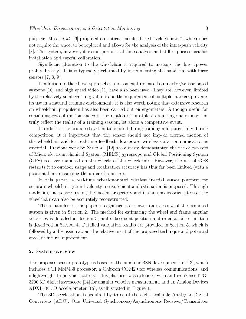
Wheelchair Displacement and Orientation Monitoring 3
purpose, Moss et al [6] proposed an optical encoder-based “velocometer”, which does
not require the wheel to be replaced and allows for the analysis of the intra-push velocity
[3]. The system, however, does not permit real-time analysis and still requires specialist
installation and careful calibration.
Significant alteration to the wheelchair is required to measure the force/power
profile directly. This is typically performed by instrumenting the hand rim with force
sensors [7, 8, 9].
In addition to the above approaches, motion capture based on marker/sensor-based
systems [10] and high speed video [11] have also been used. They are, however, limited
by the relatively small working volume and the requirement of multiple markers prevents
its use in a natural training environment. It is also worth noting that extensive research
on wheelchair propulsion has also been carried out on ergometers. Although useful for
certain aspects of motion analysis, the motion of an athlete on an ergometer may not
truly reflect the reality of a training session, let alone a competitive event.
In order for the proposed system to be used during training and potentially during
competition, it is important that the sensor should not impede normal motion of
the wheelchair and for real-time feedback, low-power wireless data communication is
essential. Previous work by Xu et al [12] has already demonstrated the use of two sets
of Micro-electromechanical System (MEMS) gyroscope and Global Positioning System
(GPS) receiver mounted on the wheels of the wheelchair. However, the use of GPS
restricts it to outdoor usage and localisation accuracy has thus far been limited (with a
positional error reaching the order of a metre).
In this paper, a real-time wheel-mounted wireless inertial sensor platform for
accurate wheelchair ground velocity measurement and estimation is proposed. Through
modelling and sensor fusion, the motion trajectory and instantaneous orientation of the
wheelchair can also be accurately reconstructed.
The remainder of this paper is organised as follows: an overview of the proposed
system is given in Section 2. The method for estimating the wheel and frame angular
velocities is detailed in Section 3, and subsequent position and orientation estimation
is described in Section 4. Detailed validation results are provided in Section 5, which is
followed by a discussion about the relative merit of the proposed technique and potential
areas of future improvement.
2. System overview
The proposed sensor prototype is based on the modular BSN development kit [13], which
includes a TI MSP430 processor, a Chipcon CC2420 for wireless communications, and
a lightweight Li-polymer battery. This platform was extended with an InvenSense ITG-
3200 3D digital gyroscope [14] for angular velocity measurement, and an Analog Devices
ADXL330 3D accelerometer [15], as illustrated in Figure 1.
The 3D acceleration is acquired by three of the eight available Analog-to-Digital
Converters (ADC). One Universal Synchronous/Asynchronous Receiver/Transmitter

Wheelchair Displacement and Orientation Monitoring 4
Sensor Board
MicrocontrollerTI MSP 430 F1611
Radio ModuleChipcon CC2420
Flash MemoryAtmel AT45DB321DB
SPI
SPI
8x ADC
2x USART
power
1x I C used
Board
Con
necto
r
GyroscopeInvenSense ITG-3200
AccelerometerAnalog D. ADXL 330
3x ADC
power
I C
Board
Con
necto
r power
Main Board
Battery Board
BatteryEEMB LP301130
Board
Con
necto
r
power
3x ADC used
2
2
Figure 1. Illustration and functional diagram of the proposed sensor hardware,depicting the main components. Front and back of the boards, top-down: sensor board(ITG-3200 gyroscope (a) and ADXL330 accelerometer (b)), main board (MSP430 (c),CC2420 (d), flash memory (e)), and battery board (f). Note that only three out ofeight available ADC and one out of two USART are used in this application.
(USART) is used to communicate with the gyroscope via the Inter-Integrated Circuit
(I2C) bus.
As the proposed system is battery-powered and wheel-mounted, low energy
consumption and light-weight sensors are necessary. Since the wheelchair velocity is
calculated directly from the angular rate velocity measured by the gyroscope, it is
necessary to choose a relatively accurate, digital, 3D gyroscope. The accelerometer
accuracy is less of a concern, as it is only used to provide a rough estimation of the
sensor orientation, as explained in Section 3.4, therefore power consumption was the
primary concern and an analog sensor was chosen.
The wireless sensor, measuring 20 × 30 × 17mm with a mass of only 10 grams, is
illustrated in Figure 2 (right). It can be mounted directly onto the rear-wheel axle using
an elastic strap or a small clamp, hence reducing significantly the installation time. The
use of digital gyroscope also reduces the need of calibration. In practice, however, it
is advisable to perform a single measurement of the intrinsic bias of the gyroscope to
ensure accuracy as discussed in Section 5.1. In order to derive the ground velocity from
the angular velocity measurement, the circumference of the wheels needs to be known.
During normal operation, the sampling rate of the sensor board is typically set to
be 30 to 50 Hz (depending on configuration) and the data is wirelessly transmitted to
a computer for real-time processing and display. It is therefore possible for the coach

Wheelchair Displacement and Orientation Monitoring 5
Figure 2. Left: court wheelchair – note the wheel camber. Right: proposed sensoron the wheel axle.
to analyse the performance in real-time, interactively. With the current antenna design
on the sensor node, the average wireless range of the sensor is about 20 meters indoor.
For all the analysis presented below, we assume that there is no skidding between the
wheels and the ground.
3. Angular velocities estimation
In order to estimate the wheelchair motion, the angular velocity of the wheel around its
axis and the angular velocity of the wheelchair frame around the vertical axis must be
derived from the gyroscope measurements. We assume that the following geometrical
constraints of the wheelchair are known: the wheel radius r, the wheel camber angle
α, and the wheelbase B, as illustrated in Figure 3 (left). This information is normally
provided by the manufacturer, or can be measured easily on site.
3.1. Gyroscope readings
Under the general wheelchair configuration, the 3D angular velocity Vgyr =
(Vgyrx, Vgyry, Vgyrz) measured by the wheel-mounted gyroscope depends on both the
angular velocity of the wheel ω̇ around its axle y and the angular velocity of the chair
frame around the vertical axis θ̇ (when the athlete is taking a turn), as illustrated in
Figure 3 (right).
The orientation Rgyr of the sensor on the wheel can be defined by a combination
of three rotations:
Rgyr = Ry(ω)Rx(δRLα)Rz(θ) (1)
where Ri(a) is the rotation around the axis i by an angle a and δRL = +1 for the
right wheel and δRL = −1 for the left one. Therefore, the overall 3D angular velocity
Wheelchair Displacement and Orientation Monitoring 6
wheelbase B
r
wheel axis (y)
(x)
(z)
camber-
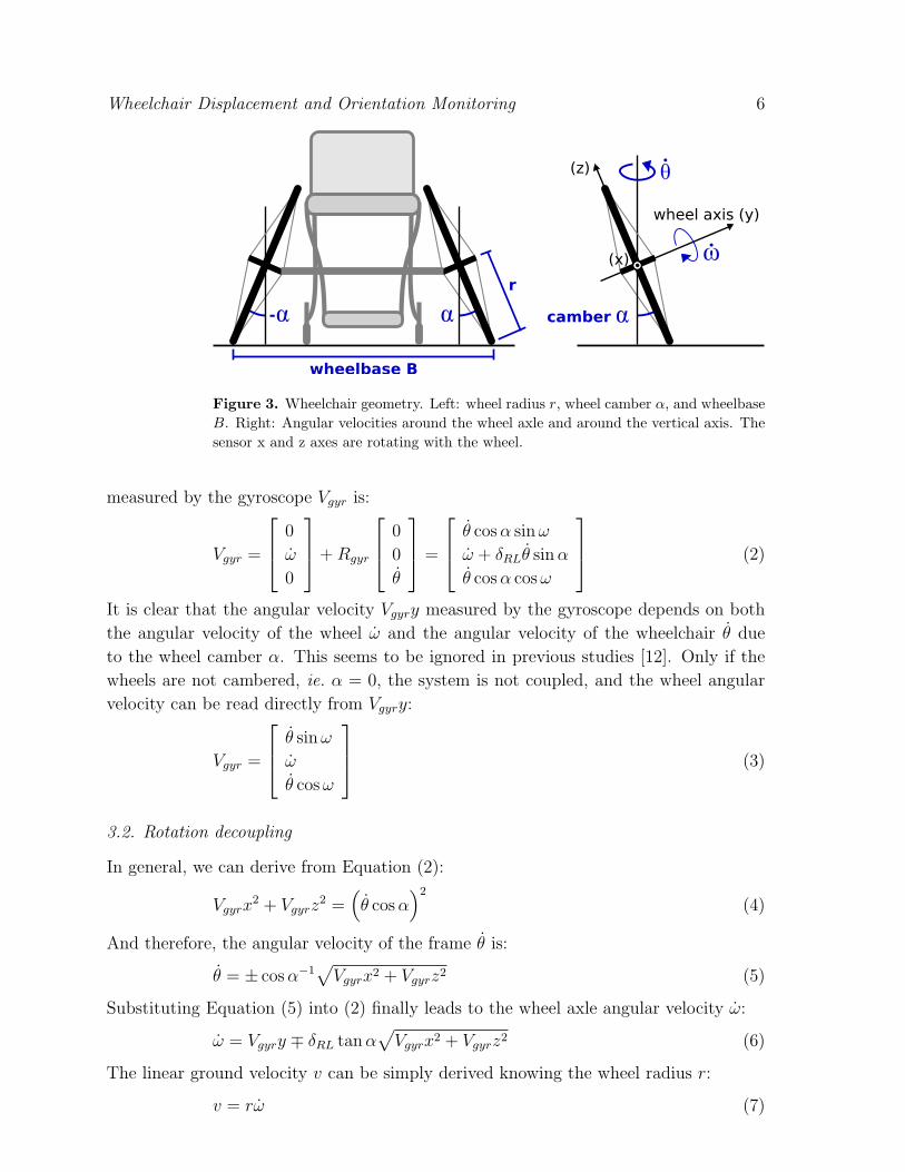
Figure 3. Wheelchair geometry. Left: wheel radius r, wheel camber α, and wheelbaseB. Right: Angular velocities around the wheel axle and around the vertical axis. Thesensor x and z axes are rotating with the wheel.
measured by the gyroscope Vgyr is:
Vgyr =
0
ω̇
0
+Rgyr
0
0
θ̇
=
θ̇ cosα sinω
ω̇ + δRLθ̇ sinα
θ̇ cosα cosω
(2)
It is clear that the angular velocity Vgyry measured by the gyroscope depends on both
the angular velocity of the wheel ω̇ and the angular velocity of the wheelchair θ̇ due
to the wheel camber α. This seems to be ignored in previous studies [12]. Only if the
wheels are not cambered, ie. α = 0, the system is not coupled, and the wheel angular
velocity can be read directly from Vgyry:
Vgyr =
θ̇ sinω
ω̇
θ̇ cosω
(3)
3.2. Rotation decoupling
In general, we can derive from Equation (2):
Vgyrx2 + Vgyrz
2 =(θ̇ cosα
)2
(4)
And therefore, the angular velocity of the frame θ̇ is:
θ̇ = ± cosα−1√Vgyrx2 + Vgyrz2 (5)
Substituting Equation (5) into (2) finally leads to the wheel axle angular velocity ω̇:
ω̇ = Vgyry ∓ δRL tanα√Vgyrx2 + Vgyrz2 (6)
The linear ground velocity v can be simply derived knowing the wheel radius r:
v = rω̇ (7)

Wheelchair Displacement and Orientation Monitoring 7
It is important to realise that the sign of the angular velocity around the vertical
axis θ̇ cannot be determined from a single 3D gyroscope reading. This can be explained
by the fact that the absolute orientation of the wheel and therefore of the sensor ω at
a given time is unknown. Therefore only the magnitude of the angular velocity can be
measured with this method.
In order to determine the sign of θ̇, a range of methods have been proposed including
the use of an additional gyroscope or using an accelerometer.
3.3. One gyroscope on each wheel
Several options can be adopted regarding the placement of a second gyroscope, such as
mounting the second sensor on the frame, which leads to a direct reading of θ̇ (assuming
a perfectly horizontal sensor), or mounting a sensor on each wheel. We have chosen the
latter for this study.
3.3.1. Geometric assumption By relying on the assumption that the wheelbase is
significantly larger than the wheel radius, it is reasonable to assume that |ω̇| > |θ̇|for at least one wheel. Therefore the sign of the difference of the measured angular
velocities on both wheel axles Vgyry can be determined. Indeed, a difference of wheel
angular velocity between the wheels will result in a global rotation of the frame around
the vertical axis.
The ground velocities (v1, v2) on each wheel can then be calculated by knowing the
wheel radius r, as in Equation 7:
(v1, v2) = r (ω̇1, ω̇2) (8)
3.3.2. Radius of curvature estimation An alternative method for calculating the
vertical rotation of the frame θ̇ can be achieved by considering the difference of ground
speed between the two wheels. This is proposed in [12], which allows the estimation of
the radius of curvature of the trajectory at a given instant. This method is specially
adapted to a non-cambered wheel situation, as it allows the use of a single axis gyroscope
on each wheel and provides a direct reading of the measurement.
R
B
d1
d2
Figure 4. Radius of curvature R and rotation angle θ estimation from the wheelspeeds.
Wheelchair Displacement and Orientation Monitoring 8
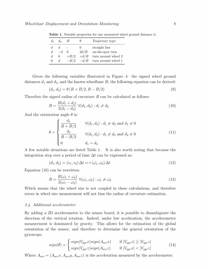
Table 1. Notable properties for any measured wheel ground distance d.
d1 d2 R θ Trajectory type
d d - 0 straight lined −d 0 2d/B on-the-spot turnd 0 +B/2 +d/B turn around wheel 20 d −B/2 −d/B turn around wheel 1
Given the following variables illustrated in Figure 4: the signed wheel ground
distances d1 and d2, and the known wheelbase B, the following equation can be derived:
(d1, d2) = θ (R +B/2, R−B/2) (9)
Therefore the signed radius of curvature R can be calculated as follows:
R =B(d1 + d2)
2(d1 − d2)∀(d1, d2) : d1 6= d2 (10)
And the orientation angle θ is:
θ =
d1
R +B/2∀(d1, d2) : d1 6= d2 and d1 6= 0
d2
R−B/2∀(d1, d2) : d1 6= d2 and d2 6= 0
0 d1 = d2
(11)
A few notable situations are listed Table 1. It is also worth noting that because the
integration step over a period of time ∆t can be expressed as:
(d1, d2) = (v1, v2) ∆t = r (ω̇1, ω̇2) ∆t (12)
Equation (10) can be rewritten:
R =B(ω̇1 + ω̇2)
2(ω̇1 − ω̇2)∀(ω̇1, ω̇2) : ω̇1 6= ω̇2 (13)
Which means that the wheel size is not coupled in these calculations, and therefore
errors in wheel size measurement will not bias the radius of curvature estimation.
3.4. Additional accelerometer
By adding a 2D accelerometer to the sensor board, it is possible to disambiguate the
direction of the vertical rotation. Indeed, under low acceleration, the accelerometer
measurement is dominated by gravity. This allows for the estimation of the global
orientation of the sensor, and therefore to determine the general orientation of the
gyroscope.
sign(θ̇) =
{sign(Vgyrx)sign(Aaccx) if |Vgyrx| ≥ |Vgyrz|sign(Vgyrz)sign(Aaccz) if |Vgyrx| < |Vgyrz|
(14)
Where Aacc = (Aaccx,Aaccy, Aaccz) is the acceleration measured by the accelerometer.
Wheelchair Displacement and Orientation Monitoring 9
The condition on Vgyr in Equation (14) ensures that the most vertical axis of the
gyroscope is used to evaluate the sign of the rotation. Since we only use the accelerometer
readings to determine the sign of the acceleration in (14), the measurement does not
need to be accurate.
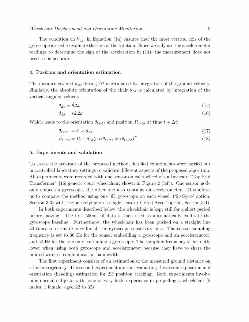
4. Position and orientation estimation
The distance covered d∆t during ∆t is estimated by integration of the ground velocity.
Similarly, the absolute orientation of the chair θ∆t is calculated by integration of the
vertical angular velocity.
θ∆t = θ̇∆t (15)
d∆t = rω̇∆t (16)
Which leads to the orientation θt+∆t and position Pt+∆t at time t+ ∆t:
θt+∆t = θt + θ∆t (17)
Pt+∆t = Pt + d∆t(cos θt+∆t, sin θt+∆t)T (18)
5. Experiments and validation
To assess the accuracy of the proposed method, detailed experiments were carried out
in controlled laboratory settings to validate different aspects of the proposed algorithm.
All experiments were recorded with one sensor on each wheel of an Invacare “Top End
Transformer” [16] generic court wheelchair, shown in Figure 2 (left). One sensor node
only embeds a gyroscope, the other one also contains an accelerometer. This allows
us to compare the method using one 3D gyroscope on each wheel, (‘2×Gyro’ option,
Section 3.3) with the one relying on a single sensor (‘Gyro+Accel’ option, Section 3.4).
In both experiments described below, the wheelchair is kept still for a short period
before moving. The first 500ms of data is then used to automatically calibrate the
gyroscope baseline. Furthermore, the wheelchair has been pushed on a straight line
30 times to estimate once for all the gyroscope sensitivity bias. The sensor sampling
frequency is set to 30 Hz for the sensor embedding a gyroscope and an accelerometer,
and 50 Hz for the one only containing a gyroscope. The sampling frequency is currently
lower when using both gyroscope and accelerometer because they have to share the
limited wireless communication bandwidth.
The first experiment consists of an estimation of the measured ground distance on
a linear trajectory. The second experiment aims at evaluating the absolute position and
orientation (heading) estimation for 2D position tracking. Both experiments involve
nine normal subjects with none or very little experience in propelling a wheelchair (8
males, 1 female, aged 22 to 32).

Wheelchair Displacement and Orientation Monitoring 10
5.1. Ground distance covered
The aim of the first experiment is to evaluate the accuracy of the ground distance
estimation. For this purpose, the proposed system was mounted on a wheelchair, the
position of which was recorded simultaneously with a Hokuyo UTM-30LX [17] scanning
LASER range finder.
As mentioned in the introduction, a relatively small number of systems exist that
are dedicated to measure a wheelchair velocity. Just as the proposed system, most of
these measure the wheel rotational velocity in the first place, from which the wheelchair
velocity is calculated. Such a measurement is subject to various inherent errors, such
as the wheel diameter and wheel skidding. Therefore it was decided not to compare
the proposed system against a system with similar intrinsic shortcomings, but to use a
system which primary measurement is completely independent of such considerations.
The LASER range finder was chosen because it provides an absolute position
measurement and is therefore not subject to integration drift and other motion-related
artefacts such as those due to wheel-skidding. Its angular resolution is 0.25 degrees, for
a distance accuracy of ±30mm in the range of 0.1 to 10 metres.
-0.2
0
0.2
0.4
0.6
0.8
1
1.2
1 2 3 4 5 6 7 8 9 10
Vel
ocity
(m
/s)
Time (s)
Figure 5. Propulsion pattern: example of unfiltered ground linear velocity (m/s)measured on a single individual performing a ‘slow’ start. It was recorded using anadditional accelerometer as detailed in Section 3.4, derived from Equation (7). Eachindividual hand push is clearly visible, followed by velocity loss due to friction. Theoverall wheelchair velocity is gradually increasing. However, the net gain in velocityfor every push is decreasing as the velocity increases, thus the velocity is bound toplateau to the subject’s maximal or desired velocity.
The nine subjects were asked to perform a succession of starts on a straight line of
approximately 9 to 10 metres (in order to stay in the 10 metres LASER range finder
optimal coverage) at three different speeds, leading to 27 trajectories. The slow speed
was chosen by each subject in order to be very comfortable, the fast one to be the fastest
they could reach. The average maximal speeds recorded were the following: 1.1, 1.6,
and 2.2 m/s. A typical start pattern is illustrated in Figure 5.

Wheelchair Displacement and Orientation Monitoring 11
0
2
4
6
8
10
1 2 3 4 5 6 7 8
Dis
tanc
e (m
)
Time (s)
LASERInertial
Figure 6. Comparison of the distance measured by the LASER range finder and theproposed inertial system on a 9 metres straight line trial at three different speeds forone subject.
The ground distance, illustrated in Figure 6, was estimated with both proposed
configurations: using one gyroscope on each wheel (2×Gyro) and using a gyroscope and
accelerometer on one single wheel (Gyro+Accel). The results are given in Table 2. Both
configurations achieve an average error rate of 50mm (ie. 0.56%) when the raw signal is
used and 18mm (ie. 0.20%) when fully calibrated.
Table 2. Distance error (millimetres) for the two proposed configurations. Averageand standard deviation (in brackets) are given for each speed and configuration.Calibrated methods work better, as they account for the gyroscope baseline drift overtime. In the uncalibrated case, this drift error accumulates over time and is thereforemore pronounced at lower speeds. When calibrated, the error is relatively constant.
Speed 2×Gyro Gyro+AccelRaw Auto-calibrated Raw Auto-calibrated
Slow 62 (27) 20 (11) 74 (35) 14 (06)Medium 46 (18) 20 (07) 41 (11) 17 (08)Fast 30 (07) 19 (07) 44 (28) 15 (09)Overall 46 20 53 15
In can be noted from Table 2 that both approaches (2xGyro and Gyro+Accel)
perform with similar trends in these specific experimental conditions. In the
uncalibrated case, both tend to have lower distance error at higher speeds, whereas
in the calibrated case the error is relatively independent from the speed.
A slight advantage is observed with the ‘Gyro+Accel’ configuration when
calibrated. This can be attributed to the near-zero wheelchair frame rotation θ̇, which
leads to Vgyr ' (0, ω̇, 0)T . In this case, the accelerometer or the second gyroscope are of
little use.
Wheelchair Displacement and Orientation Monitoring 12
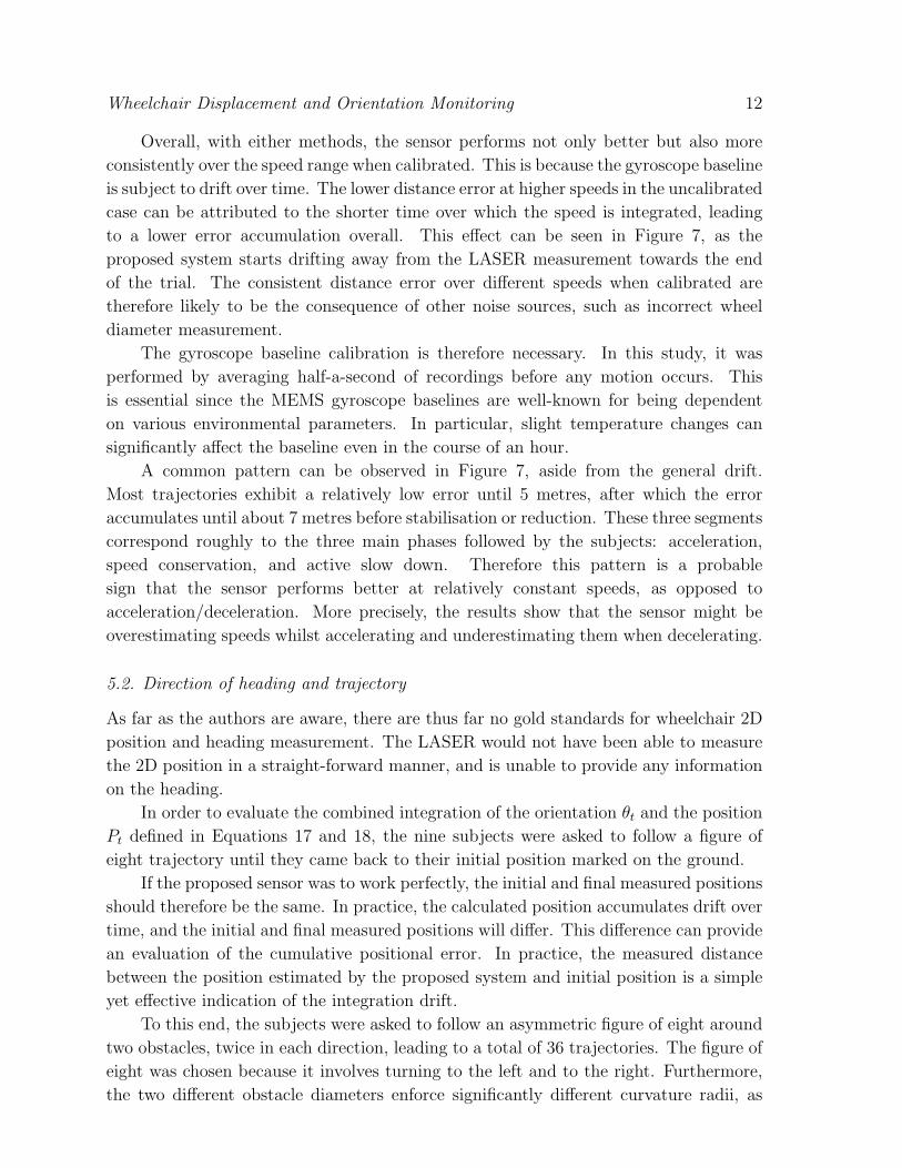
Overall, with either methods, the sensor performs not only better but also more
consistently over the speed range when calibrated. This is because the gyroscope baseline
is subject to drift over time. The lower distance error at higher speeds in the uncalibrated
case can be attributed to the shorter time over which the speed is integrated, leading
to a lower error accumulation overall. This effect can be seen in Figure 7, as the
proposed system starts drifting away from the LASER measurement towards the end
of the trial. The consistent distance error over different speeds when calibrated are
therefore likely to be the consequence of other noise sources, such as incorrect wheel
diameter measurement.
The gyroscope baseline calibration is therefore necessary. In this study, it was
performed by averaging half-a-second of recordings before any motion occurs. This
is essential since the MEMS gyroscope baselines are well-known for being dependent
on various environmental parameters. In particular, slight temperature changes can
significantly affect the baseline even in the course of an hour.
A common pattern can be observed in Figure 7, aside from the general drift.
Most trajectories exhibit a relatively low error until 5 metres, after which the error
accumulates until about 7 metres before stabilisation or reduction. These three segments
correspond roughly to the three main phases followed by the subjects: acceleration,
speed conservation, and active slow down. Therefore this pattern is a probable
sign that the sensor performs better at relatively constant speeds, as opposed to
acceleration/deceleration. More precisely, the results show that the sensor might be
overestimating speeds whilst accelerating and underestimating them when decelerating.
5.2. Direction of heading and trajectory
As far as the authors are aware, there are thus far no gold standards for wheelchair 2D
position and heading measurement. The LASER would not have been able to measure
the 2D position in a straight-forward manner, and is unable to provide any information
on the heading.
In order to evaluate the combined integration of the orientation θt and the position
Pt defined in Equations 17 and 18, the nine subjects were asked to follow a figure of
eight trajectory until they came back to their initial position marked on the ground.
If the proposed sensor was to work perfectly, the initial and final measured positions
should therefore be the same. In practice, the calculated position accumulates drift over
time, and the initial and final measured positions will differ. This difference can provide
an evaluation of the cumulative positional error. In practice, the measured distance
between the position estimated by the proposed system and initial position is a simple
yet effective indication of the integration drift.
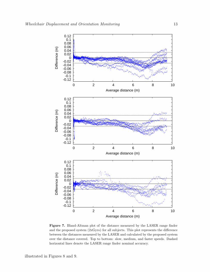
To this end, the subjects were asked to follow an asymmetric figure of eight around
two obstacles, twice in each direction, leading to a total of 36 trajectories. The figure of
eight was chosen because it involves turning to the left and to the right. Furthermore,
the two different obstacle diameters enforce significantly different curvature radii, as
Wheelchair Displacement and Orientation Monitoring 13
-0.12-0.1
-0.08-0.06-0.04-0.02
0 0.02 0.04 0.06 0.08 0.1
0.12
0 2 4 6 8 10
Diff
eren
ce (
m)
Average distance (m)
-0.12-0.1
-0.08-0.06-0.04-0.02
0 0.02 0.04 0.06 0.08 0.1
0.12
0 2 4 6 8 10
Diff
eren
ce (
m)
Average distance (m)
-0.12-0.1
-0.08-0.06-0.04-0.02
0 0.02 0.04 0.06 0.08 0.1
0.12
0 2 4 6 8 10
Diff
eren
ce (
m)
Average distance (m)
Figure 7. Bland-Altman plot of the distance measured by the LASER range finderand the proposed system (2xGyro) for all subjects. This plot represents the differencebetween the distances measured by the LASER and calculated by the proposed systemover the distance covered. Top to bottom: slow, medium, and faster speeds. Dashedhorizontal lines denote the LASER range finder nominal accuracy.
illustrated in Figures 8 and 9.
Wheelchair Displacement and Orientation Monitoring 14
Trajectory
2.0mo1.2m/
o0.2m/
start &
finish
line
Figure 8. Constraints imposed to the subjects during the figure of eight loop closureexperiment: two circular obstacles of radius 1.2 metre and 0.2 metres separated by 2.0metres.
The average measured trajectory length was 13.1 metres (standard deviation: 0.53
metres) for an average duration of 21.9 seconds (standard deviation: 5.4 seconds). From
these values, it is evident that the subjects followed a similar trajectory, but some were
much faster than others, with the slowest loop completed in 37.9 seconds against 15.8
seconds for the fastest. Most subjects managed to hit the final mark straight away, but a
few had to reverse first to then align the wheelchair with the mark. The actual accuracy
with which the subjects managed to come back on the mark is in the order of ±30mm.
This error is comparable with the nominal LASER accuracy, and is certainly much lower
than the 95mm average overall measured error presented in Table 3. Therefore, most
of the measured error is indeed induced by the proposed system. Furthermore, a few
subjects drove on the small obstacle.
The average measured distance between the initial and final position, ie. the average
error was 95mm (ie. 0.73% of the trajectory length). In order to illustrate how the
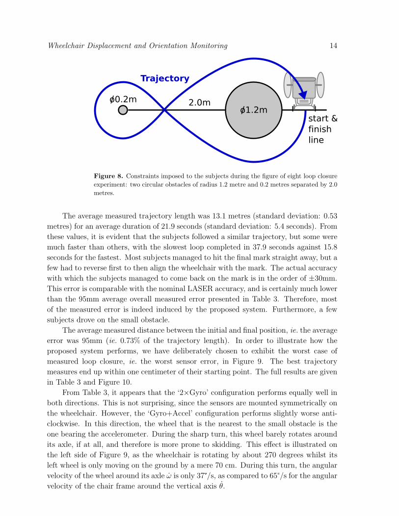
proposed system performs, we have deliberately chosen to exhibit the worst case of
measured loop closure, ie. the worst sensor error, in Figure 9. The best trajectory
measures end up within one centimeter of their starting point. The full results are given
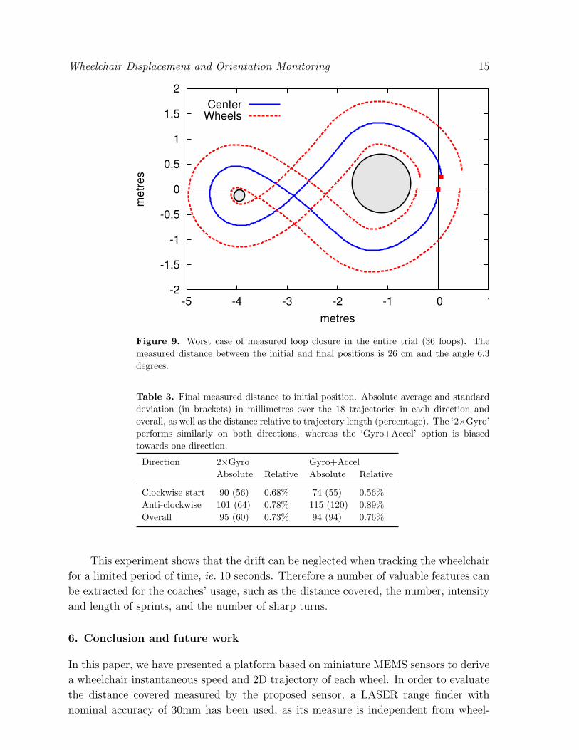
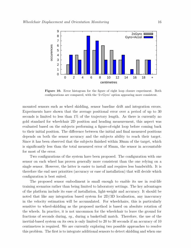
in Table 3 and Figure 10.
From Table 3, it appears that the ‘2×Gyro’ configuration performs equally well in
both directions. This is not surprising, since the sensors are mounted symmetrically on
the wheelchair. However, the ‘Gyro+Accel’ configuration performs slightly worse anti-
clockwise. In this direction, the wheel that is the nearest to the small obstacle is the
one bearing the accelerometer. During the sharp turn, this wheel barely rotates around
its axle, if at all, and therefore is more prone to skidding. This effect is illustrated on
the left side of Figure 9, as the wheelchair is rotating by about 270 degrees whilst its
left wheel is only moving on the ground by a mere 70 cm. During this turn, the angular
velocity of the wheel around its axle ω̇ is only 37°/s, as compared to 65°/s for the angular
velocity of the chair frame around the vertical axis θ̇.
Wheelchair Displacement and Orientation Monitoring 15
-2
-1.5
-1
-0.5
0
0.5
1
1.5
2
-5 -4 -3 -2 -1 0 1
metr
es
metres
Center
Wheels
Figure 9. Worst case of measured loop closure in the entire trial (36 loops). Themeasured distance between the initial and final positions is 26 cm and the angle 6.3degrees.
Table 3. Final measured distance to initial position. Absolute average and standarddeviation (in brackets) in millimetres over the 18 trajectories in each direction andoverall, as well as the distance relative to trajectory length (percentage). The ‘2×Gyro’performs similarly on both directions, whereas the ‘Gyro+Accel’ option is biasedtowards one direction.
Direction 2×Gyro Gyro+AccelAbsolute Relative Absolute Relative
Clockwise start 90 (56) 0.68% 74 (55) 0.56%Anti-clockwise 101 (64) 0.78% 115 (120) 0.89%Overall 95 (60) 0.73% 94 (94) 0.76%
This experiment shows that the drift can be neglected when tracking the wheelchair
for a limited period of time, ie. 10 seconds. Therefore a number of valuable features can
be extracted for the coaches’ usage, such as the distance covered, the number, intensity
and length of sprints, and the number of sharp turns.
6. Conclusion and future work
In this paper, we have presented a platform based on miniature MEMS sensors to derive
a wheelchair instantaneous speed and 2D trajectory of each wheel. In order to evaluate
the distance covered measured by the proposed sensor, a LASER range finder with
nominal accuracy of 30mm has been used, as its measure is independent from wheel-
Wheelchair Displacement and Orientation Monitoring 16
0
1
2
3
4
5
6
7
8
9
0 2 4 6 8 10 12 14 16 18 +
occu
renc
es
centimetres
2xGyroGyro+Accel
Figure 10. Error histogram for the figure of eight loop closure experiment. Bothconfigurations are compared, with the ‘2×Gyro’ option appearing more consistent.
mounted sensors such as wheel skidding, sensor baseline drift and integration errors.
Experiments have shown that the average positional error over a period of up to 30
seconds is limited to less than 1% of the trajectory length. As there is currently no
gold standard for wheelchair 2D position and heading measurement, this aspect was
evaluated based on the subjects performing a figure-of-eight loop before coming back
to their initial position. The difference between the initial and final measured positions
depends on both the sensor accuracy and the subjects ability to reach their target.
Since it has been observed that the subjects finished within 30mm of the target, which
is significantly less than the total measured error of 95mm, the sensor in accountable
for most of the error.
Two configurations of the system have been proposed. The configuration with one
sensor on each wheel has proven generally more consistent than the one relying on a
single sensor. However, the latter is easier to install and requires less bandwidth. It is
therefore the end user priorities (accuracy or ease of installation) that will decide which
configuration is best suited.
The proposed sensor embodiment is small enough to enable its use in real-life
training scenarios rather than being limited to laboratory settings. The key advantages
of the platform include its ease of installation, light-weight and accuracy. It should be
noted that like any integration based system for 2D/3D localisation, any inaccuracy
in the velocity estimation will be accumulated. For wheelchairs, this is particularly
sensitive to wheel-skidding as the proposed method is based on absolute rotation of
the wheels. In practice, it is not uncommon for the wheelchair to leave the ground for
fractions of seconds during, eg., during a basketball match. Therefore, the use of the
inertial-based system on its own is only limited to 20 to 30 seconds if an accuracy of 10
centimetres is required. We are currently exploring two possible approaches to resolve
this problem. The first is to integrate additional sensors to detect skidding and when one
Wheelchair Displacement and Orientation Monitoring 17
of the wheels is completely air-borne during motion. The second is to use complementary
localisation system such as those based on video [18, 19] and RF/ultrasound beacons.
Indoor video-based tracking systems can reach an accuracy of less than 10
centimetres, and this information can be used to reset the inherent sensor drift
periodically. Current problems associated with video-based tracking system are due
to the relatively high computational cost and low sampling rate. It is also limited by
the requirement of a direct line-of-sight. This can be error prone when several athletes
are moving in close proximity or mutually occluding each other. Most video-based
algorithms are unable to maintain the correspondence between a tracked subject in the
image space and its actual identity. In this regard, the combined use of the wireless
sensors and video tracking can offer an attractive way forward for accurate real-time
tracking for extended periods of time. For this approach to be effective, however, issues
related to data association such as those described in [20] based on motion signatures
will need to be addressed.
Although the proposed implementation has been initially targeted at sport-related
applications, it also demonstrates important healthcare potential for people with
disabilities. Indeed, its temporal resolution allows to derive detailed propulsion profile
that could be used to optimise hand push frequency and force, as proposed by [5]. This
could be used to monitor a patient’s rehabilitation progress during his/her activities of
daily living, rather than just to capture a snapshot measurement during a visit to a
specialised rehabilitation clinic. Furthermore, continuous monitoring can be utilised to
assess the patient’s general mobility and musculoskeletal strength, which is important
for their general well-being.
Acknowledgments
The authors would like to thank the financial support by the UK Engineering and
Physical Sciences Research Council (EPSRC) and Dr Vicky Tolfrey and Barry Mason
from Loughborough University for lending the Invacare wheelchair used for experiments
carried out in this study.
References
[1] E. Prystupa, T. Prystupa, and E. Bolach. Developmental trends in sports for the disabled. thecase of summer paralympics. Human Movement, 7:77–83, 2006.
[2] K. D. Coutts. Dynamics of wheelchair basketball. Medicine & Science in Sports & Exercise,24:231–234, 1992.
[3] A. D. Moss, N. E. Fowler, and V. L. Goosey-Tolfrey. The intra-push velocity profile of the over-ground racing wheelchair sprint start. Journal of Biomechanics, 38(1):15–22, 2005.
[4] Three Rivers. SmartWheel. http://www.3rivers.com/SmartWheel.pdf [accessed: 29/04/2011].[5] Rachel E. Cowan, Michael L. Boninger, Bonita J. Sawatzky, Brian D. Mazoyer, and Rory A.
Cooper. Preliminary outcomes of the smartwheel users’ group database: A proposed frameworkfor clinicians to objectively evaluate manual wheelchair propulsion. Archives of PhysicalMedicine and Rehabilitation, 89(2):260–268, 2008.
Wheelchair Displacement and Orientation Monitoring 18
[6] A. D. Moss, N. E. Fowler, and V. L. Tolfrey. A telemetry-based velocometer to measure wheelchairvelocity. Journal of Biomechanics, 36(2):253–257, 2003.
[7] M. Mallakzadeh and F. Sassani. An experimental technique to verify an instrumented wheelchair.Experimental Techniques, 31:25–33, 2007.
[8] Victoria L. Goosey-Tolfrey, Neil E. Fowler, Ian G. Campbell, and Simon D. Iwnicki. A kineticanalysis of trained wheelchair racers during two speeds of propulsion. Medical Engineering &Physics, 23(4):259–266, 2001.
[9] Frazer-Nash. Powerwheel. http://www.fnc.co.uk/CaseStudyBiomedicalEngineeringPowerwheel/tabid/308/language/en-GB/Default.aspx [accessed: 29/04/2011].
[10] Alexander W. Hooke, Melissa M.B. Morrow, Kai-Nan An, and Kenton R.Kaufman. Capturing wheelchair propulsion kinematics using inertial sensors.http://www.asbweb.org/conferences/2009/911.pdf [accessed: 29/04/2011].
[11] R.A. Cooper, R.N. Robertson, D.P. VanSickle, M.L. Boninger, and S.D. Shimada. Projection ofthe point of force application onto a palmar plane of the hand during wheelchair propulsion.IEEE Transactions on Rehabilitation Engineering, 4(3):133–142, September 1996.
[12] Hai Xu, Jang Ching Chua, Michael Burton, Kefei Zhang, Franz Konstantin Fuss, and AleksandarSubic. Development of low cost on-board velocity and position measurement system forwheelchair sports. Procedia Engineering, 2(2):3121–3126, 2010. The Engineering of Sport 8- Engineering Emotion.
[13] Benny Lo and Guang-Zhong Yang. Key technical challenges and current implementations of bodysensor networks. In Proceedings of the International Workshop on Wearable and ImplantableBody Sensor Networks (BSN), pages 1–5, 2005.
[14] InvenSense. ITG-3200. http://invensense.com/mems/gyro/itg3200.html [accessed: 29/04/2011].[15] Analog Devices. ADXL330. http://www.analog.com/en/sensors/inertial-sensors/adxl330/
products/product.html [accessed: 29/04/2011].[16] Invacare. Top End Transformer All Sport. http://www.topendwheelchair.co.uk/products/
basketball/transformer-all-sport.aspx [accessed: 29/04/2011].[17] Hokuyo. UTM-30LX scanning LASER range finder. http://www.hokuyo-aut.jp/02sensor/
07scanner/utm 30lx.html [accessed: 29/04/2011].[18] Julien Pansiot, Ahmed Elsaify, Benny Lo, and Guang-Zhong Yang. RACKET: Real-time
autonomous computation of kinematic elements in tennis. In IEEE 12th InternationalConference on Computer Vision Workshops (ICCV Workshops) – Fifth IEEE Workshop onEmbedded Computer Vision, pages 773–779, Kyoto, Japan, 2009.
[19] Karine J. Sarro, Milton S. Misuta, Brendan Burkett, Laurie A. Malone, and Ricardo M. L. Barros.Tracking of wheelchair rugby players in the 2008 demolition derby final. Journal of SportsSciences, 28:193–200, 2010.
[20] Douglas McIlwraith, Julien Pansiot, James Ballantyne, Salman Valibeik, and Guang-Zhong Yang.Structure learning for activity recognition in robotic assisted intelligent environments. InIEEE/RSJ International Conference on Intelligent RObots and Systems (IROS), pages 4644–4649, St. Louis, MO, 2009.