Wisam Project 579 - Web Services Overviewweb.cecs.pdx.edu/~mperkows/CLASS_479/QUANTA/10. base...
30
1 Winter 2014 Project ECE 579 Wisam Khalid Abdulkader Intelligent Robotics II Professor Mark Perkowski
Transcript of Wisam Project 579 - Web Services Overviewweb.cecs.pdx.edu/~mperkows/CLASS_479/QUANTA/10. base...

1
Winter 2014 Project
ECE 579
Wisam Khalid Abdulkader
Intelligent Robotics II
Professor Mark Perkowski

2
Contents Introduction ................................................................................................................................. 3
Navigation and Localization .......................................................................................................... 5
Obstacle Avoidance ...................................................................................................................... 5
Robot specification and Controls .................................................................................................. 5
PHYSICAL CHARACTERISTICS..........................................................................................................6
MAIN COMPONENTS......................................................................................................................6
Deck(s) and Console...................................................................................................................7
Body, Nose, and Accessory Panels.............................................................................................8
Sonar Arrays with Gain Adjustment.........................................................................................9
Motors and Position Encoders..................................................................................................10
Batteries and Power.................................................................................................................11
ELECTRONICS................................................................................................................................12
Motor-Power Board..................................................................................................................12
Microcontroller.........................................................................................................................12
Sonar Boards............................................................................................................................13
CONTROLS, PORTS, AND INDICATORS..........................................................................................13
Main Power, Fuse, and Indicator..............................................................................................13
Recharge/Power Port................................................................................................................14
Liquid-Crystal Display & Contrast Adjustment..........................................................................14
RESET and MOTORS..................................................................................................................16
SERIAL.......................................................................................................................................16
RADIO.......................................................................................................................................17
FLASH.......................................................................................................................................18
PEOPLEBOT SENSORS AND EMERGENCY STOP............................................................................18
SAFETYWATCHDOGS AND CONFIGURATION...............................................................................18
Software .............................................................................................................................. …..…20
Simulation....................................................................................................................................22
Working with the real robot........................................................................................................27
Summary ............................................................................................................. …………………..…29
3
PeopleBot Localization I. Introduction
The robot localization problem is a key problem in making truly autonomous
robots. It can be difficult to determine what to do next. In order to localize itself, a
robot has access to relative and absolute measurements giving the robot feedback
about its driving actions and the situation of the environment around the robot. Given
this information, the robot has to determine its location as accurately as possible.
What makes this difficult is the existence of uncertainty in both the driving and the
sensing of the robot.
Imagine yourself walking down a street. The street is filled with obstacles,
like houses, trees, and other people. You want to go to the supermarket. With your
eyes closed. You will most probably find it rather difficult to find your way to the
supermarket. Even if you know exactly which route to walk and even if there are no
other people blocking the route. Fortunately, most of us have eyes that help us in
finding our way. At every movement we make, our eyes tell us where that movement
brought us in the world. They constantly correct the imperfections of our
movements. You do not realize how inaccurate the movements that you make are,
until you try to walk a straight line with eyes closed. Even though you think that the
steps you make are steps on a straight line, it will probably quickly feel like you are
moving away from the line. You will probably even start to lose your balance trying
to stay on the line. Walking down a virtual line with your eyes open in general does
not cause many problems. From the information that you get from your eyes, and
other senses, you constantly obtain an idea of where you are in the world. You use
this idea to decide what to do next, for example to move towards the line if you are
moving away from it. Robots that move freely in the world have the same problems

4
as humans when walking through the world. If they only move around not looking
at where their actions take them, they will get lost because of imperfections in their
moving mechanisms and the environment. Like humans, using eyes or other sensors,
robots can detect these imperfections and get a better idea of where they are.
Figure1: PeopleBot Robot

5
II. Navigation and Localization Robot navigation is the task of an autonomous robot to move safely from one
location to another. The general problem of navigation can be formulated in three
questions:
i. Where am I? The robot has to know where it is in order to make useful
decisions. Finding out the whereabouts of the robot is called robotic
localization.
ii. Where am I going? In order to fulfill some task the robot has to know where
it is going. It has to identify a goal and this problem is therefore known as goal
recognition.
iii. How do I get there? Once the robot knows where it is and where it has to go
it has to decide on how to get there. Finding a way to get to the goal is known
as path planning.
III. Obstacle Avoidance At all costs robots should avoid colliding with the obstacles in their
environments. In dynamic environments, that is, where there are multiple moving
obstacles, obstacle avoidance is a difficult problem. Although the dynamics of
moving obstacles can sometimes be predicted, like when trains run on a track,
sometimes the dynamics may be more uncertain, like playing children running
around. A robot uses path planning techniques to plan a collision free path from one
location to another location. If the obstacles in the environment are dynamic, the
path planning problem is NP-hard.
IV. Robot Specification and Controls ActivMedia’s robots may be smaller than most, but they pack an impressive
array of intelligent mobile robot capabilities that rival bigger and much more

6
expensive machines. At the same time, the powerful P2OS server with ActivMedia
Robotics client software, is fully capable of mapping its environment, finding its
way home, and performing other sophisticated path planning tasks.
1. Physical Characteristics
Weighing only 9 kg (20 pounds with one battery), the basic Pioneer 2 Mobile
Robot is lightweight, but its strong aluminum body materials and solid construction
make it virtually indestructible.
Figure 2: The Pioneer 2 physical dimensions and swing radius
2. Main Components
ActivMedia robots are composed of several main parts:
a. Deck(s) and Console
b. Body, Nose, and Accessory Panels
c. Sonar Array(s)
d. Motors and encoders
e. Batteries and Power

7
a) Deck(s) and Console
The original Pioneer 2 are one piece, the top plate of the robot. The new DXe and AT models now have hinged top-plates which let you much more easily access the internal components of the robot.
Figure 3: Pioneer 2 Console and hinged Deck The robot’s Deck is simply the flat surface for mounting projects and
accessories, such as the PTZ Robotic Camera or a laser range finder. The
PeopleBot’s have lower and upper Decks. Feed-through slots on each side of the
Deck let you conveniently route cables to the accessory panels on each side of the
robot. A removable plug in the middle of the Deck on all models5 gives you
convenient access to the interior of the robot.
In general, you should try to center the robot's payload over the drive wheels.
If you must add a heavy accessory to the edge of the Deck, counterbalance the weight
with a heavy object on the opposite end. A full complement of batteries helps balance
the robot, too.
The Pioneer 2’s or PeopleBot’s Console consists of a liquid-crystal display
(LCD), MOTORS, and RESET control buttons and indicators, and an RS232-
compatible serial port with a 9-pin DSUB connector. The Pioneer 2 and PeopleBot

8
V1 Consoles sit at the front of the Deck. The Performance PeopleBot’s Console is
in the left column. Attached directly underneath the Console is the robot’s
microcontroller.
b) Body, Nose, and Accessory Panels
The ActivMedia robot is sturdy, but lightweight aluminum Body houses the
batteries, drive motors, electronics, and other common components, including the
front and rear sonar arrays. The Body also has sufficient room, with power and signal
connectors, to support a variety of robotics accessories inside, including an A/V
wireless surveillance system, radio modems or radio Ethernet, onboard computer,
and more. a hinged rear door gives you easy access to the batteries, which you may
quickly hot-swap to refresh any of up to three batteries.
The PeopleBot V1 has a removable pedestal mounted to its base Deck. A removable
back panel gives you access to internal wiring and components, including stereo
speakers, A/V and Ethernet radios, and microphone preamplifier. On top of the
pedestal is the upper Deck where you may add components like the PTZ Robotic
Camera that normally mounts to the Deck of a Pioneer 2. PeopleBot’s also have an
additional front sonar array. PeopleBot include front and rear bump rings for
stability as well as sensitive collision detection. The PeopleBots have a Nose that is
secured by a single screw beneath the front sonar array and one on the bottom of the
robot.
Once the mounting screws are removed, simply pull the Nose away from the
Body. This provides a quick and easy way to get to the accessory boards and disk
drive of the onboard PC, as well as to the sonar gain adjustment for the front sonar
array. The Nose also is an ideal place for you to attach your own custom accessories
and sensors.

9
The robot come with removable panels on each side through which you may
install accessory connectors and controls. A special side panel comes with the
onboard PC option, for example, which gives users monitor, keyboard, mouse, and
10Base-T Ethernet access, as well as the means to reset and switch power for the
onboard computer.
c) Sonar Arrays with Gain Adjustment
Natively, ActivMedia robots support both front and rear sonar arrays, each
with eight transducers that provide object detection and range information for
features recognition, as well as navigation around obstacles. With sonar expansion
electronics, you may add up to 16 more sonar in two additional arrays of eight sonar
each. PeopleBots, for instance, have an additional array at the front of the upper
Deck.
The sonar positions in all arrays are fixed: one on each side, and six facing
outward at 20-degree intervals. Together, fore and aft sonar arrays provide 360
degrees of nearly seamless sensing for the platform.
Each sonar array comes with its own driver electronics for independent
control. Each arrays’ sonar are multiplexed; the sonar acquisition rate is 25 Hz (40
milliseconds per sonar per array. Sensitivity ranges from ten centimeters (six inches)
to nearly five meters (16 feet). You may control the sonar’s firing pattern through
software; the default is left-to-right in sequence 0 to 7 for each array.
The driver electronics for each array is calibrated at the factory. However, you
may adjust the array’s sensitivity and range to accommodate differing operating
environments. The sonar gain control is on the underside of the sonar driver board,
which is attached to the floor of each sonar module.
Sonar sensitivity adjustment controls are accessible directly, although you
may need to remove the Gripper to access the front sonar, if you have that accessory

10
attached. For the front sonar, for instance, locate a hole near the front underside of
the array through which you can see the cap of the sonar-gain adjustment
potentiometer. Using a small flat-blade screwdriver, turn the gain control
counterclockwise to make the sonar less sensitive to external noise and false echoes.
Low sonar-gain settings reduce the robot’s ability to see small objects. Under
some circumstances, that is desirable. For instance, attenuate the sonar if you are
operating in a noisy environment or on uneven or highly reflective floor, a heavy
shag carpet, for example. If the sonar are too sensitive, they will “see” the carpet
immediately ahead of the robot as an obstacle.
Increase the sensitivity of the sonar by turning the gain-adjustment screw
clockwise, making them more likely to see small objects or objects at a greater
distance. For instance, increase the gain if you are operating in a relatively quiet and
open environment with a smooth floor surface.
Figure 4: ActivMedia robot sonar array
d) Motors and Position Encoders
PeopleBot drive systems is high-speed, high-torque, reversible-DC motors,
each equipped with a high-resolution optical quadrature shaft encoder for precise

11
position and speed sensing and advanced dead-reckoning. Motor gearhead ratios and
encoder ticks per revolution vary by robot model.
e) Batteries and Power
PeopleBot robots may contain up to three, hot-swappable, seven ampere-hour,
12 volts direct-current (VDC) sealed lead/acid batteries (total of 252 watt-hours),
accessible through a hinged and latched back door. We provide a suction cup tool to
help grab and slide each battery out of its bay. Spring contacts on the robot’s battery
power board alleviate the need for manually attaching and detaching power cables
or connectors.
Battery life, of course, depends on the configuration of accessories and motor
activity. PeopleBot charge life typically ranges from two to three hours. If you don’t
use the motors, your robot’s microcontroller will run for several days on a single
battery charge.
IMPORTANT: Batteries have a significant impact on the balance and
operation of your robot. Under most conditions, we recommend operating with three
batteries. Otherwise, a single battery should be mounted in the center, or two
batteries inserted on each side of the battery container. Typical recharge time using
the recommended accessory (800 mA) charger varies according to the discharge
state; it is roughly equal to three hours per volt per battery. The Power Cube
accessory allows simultaneous recharge of three swappable batteries outside the
robot.
With the optional high-speed (4A maximum current) charger, recharge time
is greatly reduced. It also supplies sufficient current to continuously operate the
robot and onboard accessories, such as the onboard PC and radios. But with the

12
higher-current charger, care must be taken to charge at least two batteries at once. A
single battery may overcharge and thereby damage both itself and the robot.
3. Electronics
PeopleBot standard electronics reside on two main boards: a microcontroller
and a motor-power distribution board. Each sonar array also has a controller board
mounted in its base. A special I/O expansion board found inside the left column strut
of the Performance PeopleBot distributes User I/O for use by the robot’s joystick
port as well as it’s tabletop and break beam IR sensors.
A Main Power switch at the back of the robot controls power for the entire
system. Processor control switches and indicators fit through the Console.
a) Motor-Power Board
Inside the robot, mounted to the battery box, is the Motor-Power board. It
supplies both the 12 and five volts direct-current (VDC) power requirements of your
robot’s systems. The standard Motor-Power board has a 12-pin User-Power
connector that supports four sets of five- and 12-VDC power ports (total 1.5 ampere)
for custom accessories.
An optional computer-power section to the board supplies power for the
onboard PC. It includes a special low-power and power-down circuit that lets you
gently shut down the onboard PC without direct connection through a keyboard or
monitor.
b) Microcontroller
The Pioneer 2/PeopleBot microcontroller has a 20 MHz Siemens 88C166
microprocessor with integrated 32K FLASH-ROM. It also has 32K of dynamic

13
RAM, two RS232-compatible serial ports, several digital and analog-to-digital, and
PSU I/O user-accessible ports, and an eight-bit expansion bus. All of the I/O ports,
except those used for the motors, encoders, and sonar, are available to the user for
accessory hardware. The embedded operating software (P2OS) lets you support and
manage each of these I/O ports.
c) Sonar Boards
Associated with each sonar array forward and rear is a sonar multiplexer/firing
board. Wire leads to the individual sonar plug into a 16-pin connector on the board.
A 10-conductor power/signal cable connects the sonar board with the
microcontroller.
4. Controls, Ports, and Indicators
a) Main Power, Fuse, and Indicator
A single slide-switch on the rear left panel of Pioneer 2 and PeopleBot robots
controls power to the entire robot and all its integrated accessories. Up is ON; down
is OFF. A red LED on the Console indicates Main Power.
Inside, on the top right side of the battery box (accessible through the hinged
back door) is the Main Power Fuse. It is an automotive-type (spade terminals) 15A
fuse designed for tool-less replacement. To the left of the fuse, on the same battery
connection board, is the main power relay, which isolates the high-ampere draw of
the robot system from the Main Power Switch.

14
b) Recharge/Power Port
Below the Main Power Switch is the battery recharger port. It provides 12
VDC power to the robot's electronics, motors, and accessories, even without
batteries. Use the recommended accessory power charger or equivalent.
The robot’s batteries should be maintained in a charged state above 11 VDC,
as indicated on the Console LCD. We recommend recharging the battery when it
falls below 11 VDC, even though the robot may continue to operate below 10 VDC.
The microcontroller will sound a warning when the battery voltage falls below that
level, and the optional computer power circuitry will automatically shut down the
onboard PC. Discharging the batteries below 10 VDC may permanently damage
them.
You may continue to operate the robot while charging its batteries, although
that will lengthen the recharge time. Because the onboard PC draws much current,
even the high-speed 4A charger will not be able to fully recharge the batteries unless
you power down the PC.8
If you have only one battery onboard, plug your robot into the charger before
“hot-swapping” the exhausted battery for a fresh one. To hot-swap two or three
batteries, replace each battery one-at-a-time, leaving at least one battery in place to
supply power to the robot. The Power Cube accessory is a convenient way to
externally recharge one to three of the hot-swapped batteries.
c) Liquid-Crystal Display & Contrast Adjustment
Information about your robot's state and connections appears on a 32-
character (two lines) liquid-crystal display (LCD) on the Console. When under
control of the P2OS servers, for example, the display shows the state of

15
communication with the client computer, along with the battery voltage and a
blinking "heartbeat" asterisk (*) in the second line of text.
A small, contrast-adjustment potentiometer for the LCD is inset next to the
display. Make sure the Main Power switch is ON and the battery is well charged.
Then, using a small, flat-blade screwdriver, turn the adjustment screw to darken or
lighten the screen so that the characters are clearly visible under your lighting
conditions.
Figure 5: The Console
d) RESET and MOTORS
The RESET (red) and MOTORS (white) push-button switches on the Console
affect the microcontroller’s logic and motor-driver systems.
When pressed alone, RESET puts the microcontroller into its start-up state,
disrupting any running program or client connection. It also disables the drive
motors—just as if you cycle Main Power. But, unlike a cold-power restart, RESET

16
preserves the contents of the microcontroller's RAM, so any user programs
downloaded in standalone mode get restarted.
The MOTORS button and its associated green LED are under software
control. Normally, your ActivMedia robot's motors are disabled when not connected
with a client, such as Navigator or Saphira. When first connected with a client,9 the
motors remain disabled (LED flashes) until you press and release the MOTORS
button. Pressing and releasing the white MOTORS button then enables/disables the
motors as long as the robot remains connected with a client.10 The green LED
should light continuously when the motors are enabled and blink ON and OFF when
disengaged.
When not connected with a client, pressing and releasing the MOTORS button
puts your robot into joystick-drive mode. A subsequent press and release of the
MOTORS button puts the robot into Self-Test Mode that exercises the robot's drive,
controller, and I/O systems. Press and hold the MOTORS button in combination
with the RESET button to put the microcontroller into a special system-download
mode for reprogramming the onboard FLASH ROM.
e) SERIAL
ActivMedia robot's microcontroller has two serial ports and three connectors.
One connector, labeled SERIAL, is a standard 9-pin D-SUB receptacle located on
the Console and is for direct RS232-compatible serial data communication between
the microcontroller and a client computer. This “Host” serial port shares its three-
line transmit, receive, and ground connections with one of the two serial connectors
that is inside the robot.
17
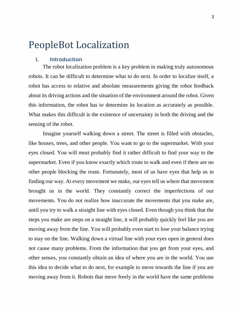
Amber LEDs on each side of the Host serial port light during data-exchange
activity transmitted from or received by the microcontroller. I used Serial port for
communicating with the Robot.
Figure 6: Serial Communication
f) RADIO
The RADIO slide switch on your robot’s Console controls power to the
optional radio modem or Ethernet radio. It does not affect the SERIAL port functions
directly, but you must switch the radio modem’s power OFF if you use the Console
SERIAL port to connect a piggyback laptop or another external computer to the
robot.
The radio modem gets power as well as signals through the internal, shared
Host serial port and can interfere with Console SERIAL communications. In some
cases, you may have to physically remove the radio serial connection from the
microcontroller to eliminate that interference.

18
g) FLASH
A slide switch labeled FLASH is recessed into the Console. It write-protects
the FLASH ROM-stored P2OS software and your robot's operating parameters.
When switched forward, FLASH is enabled for writing. ActivMedia’s P2OS
maintenance utilities warn you if FLASH is disabled.
5. PeopleBot Sensors and Emergency STOP
Performance PeopleBot’s tabletop sensors are very reliable diffuse IR
detectors mounted to the front of the robot and which detect obstacles, particularly
tabletops or rope barriers, that otherwise aren’t detected by the sonars. The tabletop
IR detectors respond to any surface except glass or other mirrored surfaces, and can
detect objects as thin as a human finger. They are oriented to trigger when an object
is 28 cm (11.5 inches) or nearer to the front of the robot and 3.75 cm (1.5 inches) at
the height of the lower deck.
Two “breakbeam” IR sensors, one on each side 3.75 cm (1.5 inches) forward
of the left and right column struts and between the top and lower Decks of the
Performance PeopleBot, sense objects which intrude into the robot’s profile, but
which may not be otherwise detected by the sonars or tabletop IR sensors.
Since the tabletop and breakbeam IR sensors are connected to User I/O digital
ports, their states are communicated from the P2OS server to a connected client,
such as Saphira, in the standard Server Information Packet.
6. Safety Watchdogs and Configuration
Pioneer 2’s and PeopleBot’s standard onboard software, P2OS, contains a
communications watchdog that will halt motion if communications between a client
19
computer and the server are disrupted for a set time interval, nominally two seconds
(watchdog parameter). The robot will automatically resume activity, including
motion, as soon as communications are restored.
P2OS also contains a stall monitor. If the drive exerts a PWM pulse that equals
or exceeds a configurable level and the wheels fail to turn (stallval), motor power is
cut off for a configurable amount of time (stallwait). The server software also
notifies the client which motor is stalled. When the stallwait time elapses, motor
power automatically switches back ON and motion continues under server control.
All these “failsafe” mechanisms help ensure that your robot will not cause
damage or be damaged during operation. You may reconfigure the communications,
drive current, and stallwait values to suit your application.
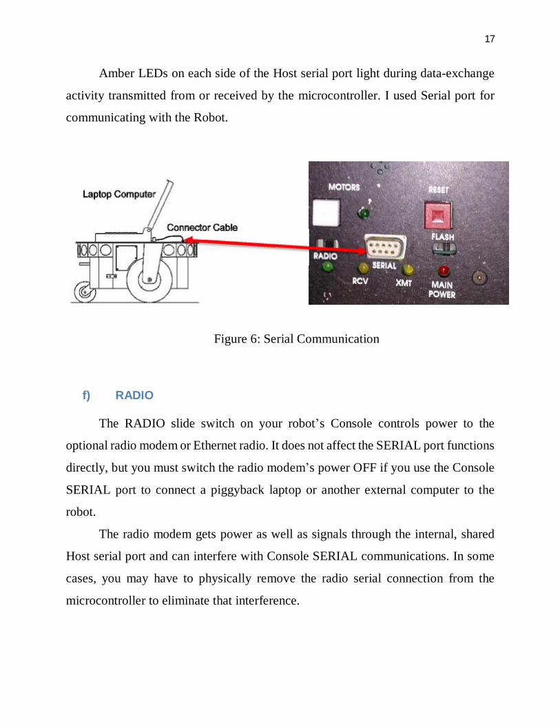
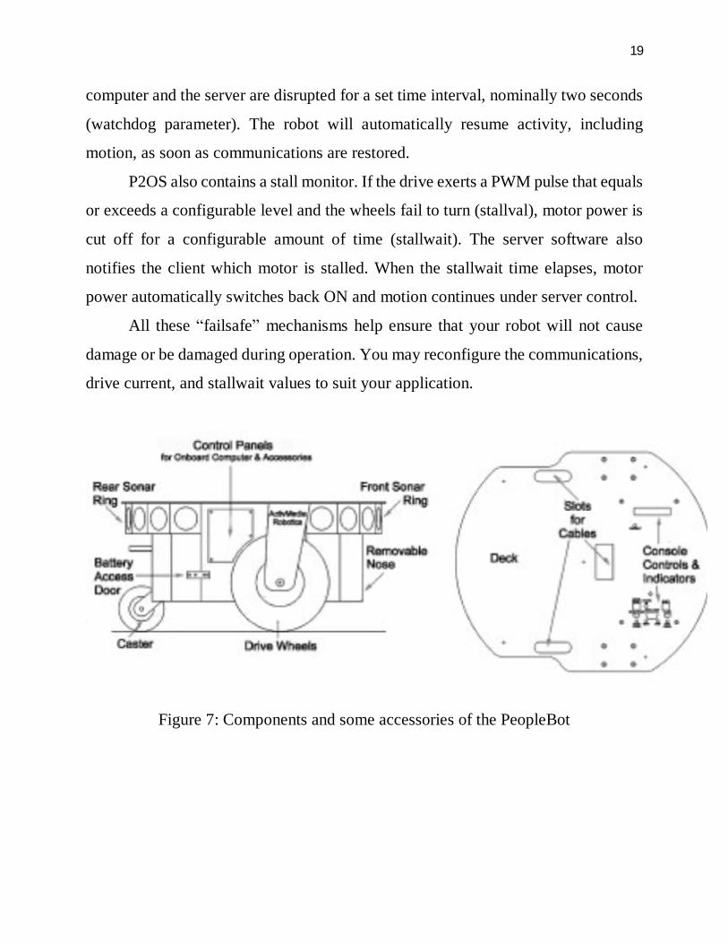
Figure 7: Components and some accessories of the PeopleBot

20
V. Software As we see before, - PeopleBot Mobile Robots are intelligent mobile robots,
ActivMedia’s robots are truly intelligent, off-the-shelf mobile platforms, containing
all of the basic components for sensing and navigation in a real-world environment,
including battery power, drive motors and wheels, position-speed encoders,
integrated sensors, and accessories. They are all managed by an onboard
microcontroller and mobile-robot server software. ActivMedia robot also has a
variety of expansion power and I/O ports for attachment and close integration of
additional sensors and other accessories. Expansion includes an addressable I/O bus
for up to 16 devices, two RS-232 serial ports, eight digital I/O ports, five A/D ports,
PSU controllers and all accessible through a common application interface to the
robot server software, P2OS.
The software packages can be downloaded from: http://robots.mobilerobots.com/wiki/All_Software
Portland State University’s login and password were requested directly from
MobileRobots and are shown in the table below for future reference, the robot’s
serial number is necessary for any requests of support from MobileRobots.
Robot’s Serial Number PBBDBB1270
Login Portland
Password nT7>qEhy
If have a problem and can’t find the answer, send an email to [email protected] with the robot’s Serial Number (PBBDBB1270).
There are three main software packages we need to use for localization and
navigation: SonARNL, MobileEyes, and Mapper3basic. In addition to that these,

21
there is another software which is just for simulation, which is good for testing
purposes called MobileSim.
Figure 8: The complete localization and path planning solution
For now we are using Sonar-based Advanced Robotics Navigation and
Localization (SonARNL) software on your sonar-enabled robot with the
MobileEyes GUI client and Mapper3Basic map-building applications. In fact,
SonARNL works with any and all sonar-enabled MOBILEROBOTS platform—new
or old. And there is a higher performance navigation, mapping, and control features
of MOBILEROBOTS’ Advanced Robotics Navigation and Localization (ARNL)
software that uses a laser range-finder accessory and onboard PC which we don’t
use now because of the high expense of the laser range finder.

22
Figure 9: Robot Hardware and software components used for localization
After downloading and installing the software mentioned before we are ready to
navigate the robot. Now we have two choices to demonstrate how to localize our
PeopleBot robot, Simulation and real robot.
a) Simulation
The simulated SonARNL robot has three parts: MobileSim robot simulator,
SonARNL’s sonarnlServer, and the MobileEyes client. Start them up in order on
your computers.
Step 1. Run MobileSim
PC
MobileEyes
FRONT SONARS IDs 0-7
BACK SONARS IDs 8-15
FRONT BUMPERS
BACK BUMPERS
BASE CONTROL BOARDS
USB/RS-232
LEFT MOTOR
RIGHT MOTOR
Mapper3Basic
MobileSim
SonARNL
PIONEER 2 ROBOT BASE

23
Load a simulated world and the simulated robot into MobileSim from its start-up
dialog or by explicit declaration as arguments on the start-up command line. The
default Robot model is a Pioneer 3-DX, change it to PeopleBot simulated robot.
Then after that load the map you want to localize your robot in. Note that you can
use a map called Columbia which comes with the software package.
Figure 10: The MobileSim-simulated Pioneer PeopleBot at its dock in the map
Step 2. Run SonArnlServer.exe
All MobileRobots platforms operate in a client-server environment. ARNL comes
with a demonstration server called sonarnlServer. It is through server applications
like sonarnlServer that clients like MobileEyes get control access to the robot and
its accessories, such as the pan-tilt robotic camera, as well as to all the many features

24
and functions of MobileRobots software, including ARIA, SonARNL,
ARNetworking and so on.
Like any ARIA-based application, sonarnlServer takes several arguments that direct
its connection with the robot. Once running, clients like MobileEyes also may send
commands to sonarnlServer that change these and other operating parameters.
Finally, sonarnlServer needs a map. A SonARNL map defines not only the robot’s
operating space for localization and navigation, but also defines goals like Dock for
auto-charging and other predetermined destinations. See subsequent chapters for
Mapper3Basic details.
In the Arnl/examples directory, a demonstration map is included that matches the
simulated world map loaded into MobileSim above. For the purposes of this Quick
Start demonstration, let’s just use sonarnlServer’s defaults with the sample
Columbia map. SonARNL’s sonarnlServer, through ARIA, prints out a lot of useful connection
details on the console, including robot type and networking information.

25
Figure 11: sonarnlServer connection
Step 3. Run MobileEyes Simply launch MobileEyes and, from its startup dialog, specify the IP address or
hostname of the computer that is running sonarnlServer. The hostname localhost or
IP address 127.0.0.1 usually works if sonarnlServer is running on the same PC as
you launch MobileEyes.

26
Figure 12: MobileEyes connection
After connecting you will see your robot in the map, now with this graphical user
interface you can easily localize your robot.
Going to a Goal
Using Mapper3Basic, you may embed destinations with final headings (goals) into
the map. Thereafter, they need only be referenced by name in order to have the robot
automatically drive to that position and turn to the prescribed heading once it gets
there. MobileEyes parses those goal names and displays them in its Goals: window
as well as distinctive markers in the map.
The demonstration columbia.map has several goals. Double-click, for example, the
Hallway 1 goal in the map, or choose it from the Goals: window, to have ARNL plan
a path and drive your simulated robot to it. MobileEyes displays ARNL’s planned
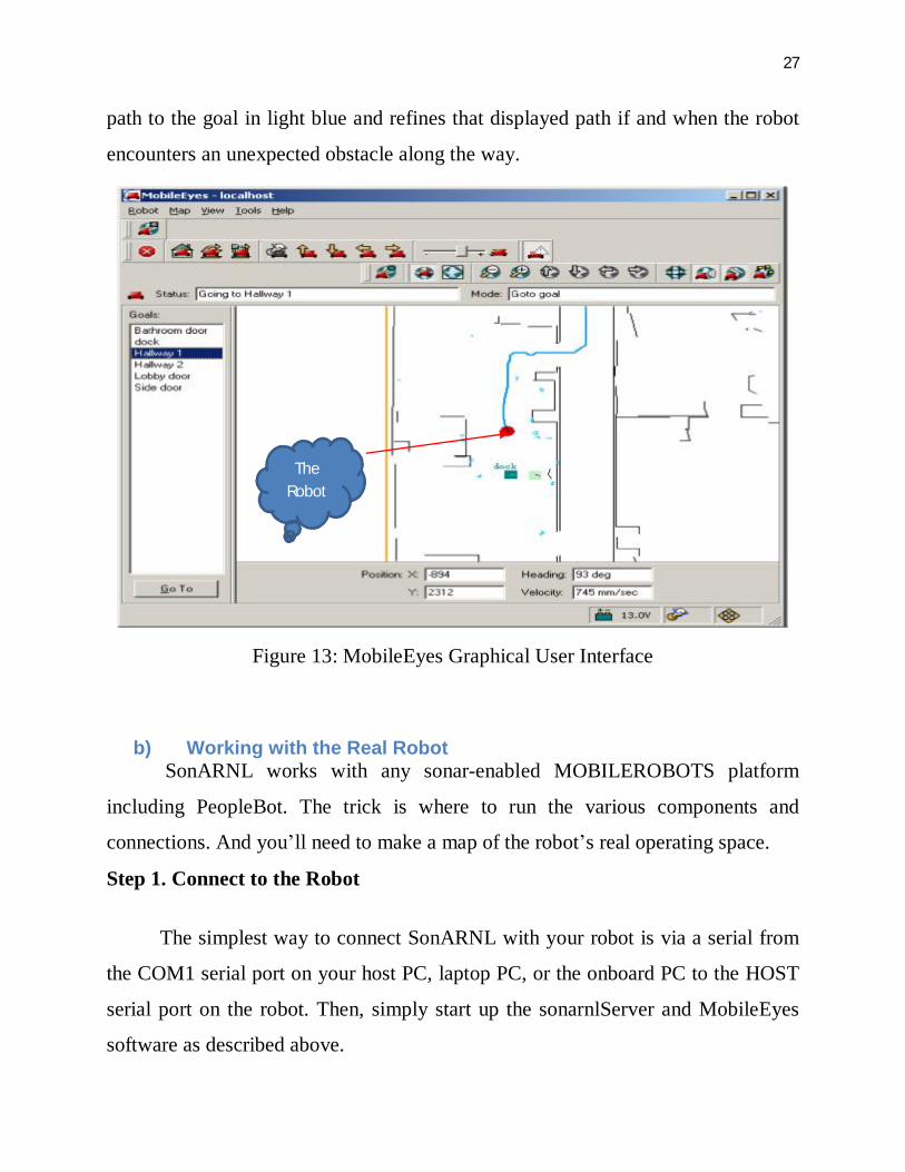
27
path to the goal in light blue and refines that displayed path if and when the robot
encounters an unexpected obstacle along the way.
Figure 13: MobileEyes Graphical User Interface
b) Working with the Real Robot
SonARNL works with any sonar-enabled MOBILEROBOTS platform
including PeopleBot. The trick is where to run the various components and
connections. And you’ll need to make a map of the robot’s real operating space.
Step 1. Connect to the Robot
The simplest way to connect SonARNL with your robot is via a serial from
the COM1 serial port on your host PC, laptop PC, or the onboard PC to the HOST
serial port on the robot. Then, simply start up the sonarnlServer and MobileEyes
software as described above.
The Robot

28
In the absence of MobileSim, sonarnlServer defaults to making a connection
with the robot through that default serial port.
Step 2. Run SonArnlServer.exe
Step 3. Run MobileEyes
You can notice that step two and three is exactly the same as explained before with
simulation. Mapper3Basic Use the Mapper3Basic program to create maps, as well as add and edit forbidden
spaces and goals. Mapper3Basic, in collaboration with sonarnlServer and
comparable servers, also lets you manage your robot’s map files remotely over the
network for deployment and use on your robots.
First, a quick word about the various map types and elements. If you have an ARNL-
enabled MOBILEROBOTS platform, use it to make maps for all your robots.
SonARNL and ARNL maps are interchangeable.
Also, Mapper3 and Mapper3Basic are the same application with identical features
except the former also converts “2d” scan files created with an ARNL-enabled robot
and containing raw laser and odometry readings into a map. Mapper3Basic cannot.
Maps created through Mapper3 and ARNL consist of occupancy grid-points and
derived lines. Maps made with Mapper3Basic consist only of lines; no points.

29
Figure 14: Maps consist of occupancy-grid points (left) and extracted lines (right).
For localization, SonARNL can only use lines like those you may have drawn
yourself with Mapper3Basic or add with Mapper3. For path-planning, SonARNL
uses both points and lines. MobileSim uses both points and lines, too, as its view of
the world. ARNL uses both lines and points for both localization and path-planning.
Both a map’s points and lines normally get displayed by Mapper3Basic or Mapper3.
VI. Summary
In this work we were able to connect and control the robot for navigation and
localization with no additional hardware that could cost us, in the next step we should
work to create a map and since we can’t use mapper software, we should create our
map using Mapper3Basic.
Mapper3Basic provides a wide range of tools to create and edit your maps
into the best representations of your robot’s real operating environments. The
important thing to note, however, is that the map is only as good as your

30
measurements, and your robot’s ability to navigate the map is directly related to the
fidelity of the map. Measure twice and once more again.