Wiring: Prototyping Physical Interaction...
43
Hernando Barragán | Interaction Design Institute Ivrea | June 2004 [email protected] Wiring: Prototyping Physical Interaction Design Thesis Committee Massimo Banzi . Associate Professor Primary advisor Casey Reas . Visiting Assistant Professor UCLA Design | Media Arts, Secondary advisor Gillian Crampton Smith . Director Andrew Davidson . Chair of the Academic Programme
Transcript of Wiring: Prototyping Physical Interaction...
Hernando Barragán | Interaction Design Institute Ivrea | June 2004
Wiring: Prototyping Physical Interaction Design
Thesis Committee
Massimo Banzi . Associate Professor
Primary advisor
Casey Reas . Visiting Assistant Professor
UCLA Design | Media Arts,
Secondary advisor
Gillian Crampton Smith . Director
Andrew Davidson . Chair of the Academic Programme
Hernando Barragán
0. Abstract
0.1 Problem
Design education and practice increasingly rely on digital technology. For designers to suc-
cessfully enter this domain they need to understand the inherent qualities in the media they
work with, such as electronics and software. Current prototyping tools for electronics and pro-
gramming are mostly targeted to engineering, robotics and technical audiences. They are hard
to learn, and the programming languages are far from useful in contexts outside a specific
technology. Designers need a teaching language and electronics prototyping system that fa-
cilitates and encourages the process of learning, that reduces the struggle with electronics
design and programming, and that are powerful and flexible enough for the needs of Interac-
tion Design.
0.2 What is it
Wiring is both a programming environment and an electronics prototyping input/output board
for exploring the electronic arts and tangible media. It can also be used to teach and learn
computer programming and prototyping with electronics. It illustrates the concept of pro-
gramming with electronics and the physical realm of hardware control which are necessary
to explore physical interaction design and tangible media aspects in the design discipline.
The Wiring software and the hardware designs of the Wiring electronic input/output board will
be freely available for download on the Web. Users will have access to the Wiring electronic in-
Wiring: Prototyping Physical Interaction Design
put/output board as well. The site contains a reference, and a number of short prototypical ex-
amples that explore the media and illustrate the code and the electronics diagrams allowing
users to learn by experimenting with them.
Wiring builds on Processing, the open source programming language developed at the Mas-
sachusetts Institute of Technology Media Lab and Interaction Design Institute Ivrea by Ben
Fry and Casey Reas. People who learn how to program using Processing can instantly move
to program in Wiring and then to other languages or scripting environments like Java, C, C++,
JavaScript, Flash or Director.
While working on their design concepts, users will be able to sketch, test their ideas and pro-
totype them, by writing small programs and downloading them to the input/output board.
The Wiring input/output board is a general purpose electronic system that includes a micro-
controller where the users’ programs will run. It provides digital and analog inputs and out-
puts and functionality that will allow users to interface all kind of sensors and actuators and
program the behaviors needed in their projects.
This project aims to support education not only in the design and art schools but also
in different types of learning environments and different types of practices. It will en-
able users to quickly prototype their ideas and concepts in the physical world, allow-
ing users to concentrate on the quality of their designs, the interaction, ideas, or con-
cepts being illustrated, rather than concentrate on showing that the technology works.
It will contribute to sharing ideas and knowledge with the wider community of interaction
design and in general to others outside this field. Because it builds on the Processing language,
it will take advantage of the existing online community of users around the world and their
collective experience. It also builds on my previous professional experience as engineer artist
and designer.

Hernando Barragán
Wiring: Prototyping Physical Interaction Design
Acknowledgments
This thesis is dedicated to my huge family, (too many to name you all guys), especially to my
grandparents Rafael y Maria, and my grandparents Antonio y Edelmira who both passed away
while I was here.
I am extremely grateful to Casey Reas for his support and encouragement; It’s been an honor
to have him as mentor and friend and a constant source of inspiration and perspective, thank
you. I thank Massimo Banzi for his support. I also thank all the members of the community at
Interaction Design Institute Ivrea past and present for their valuable insights: Gillian Cramp-
ton Smith, Andy Davidson, Bill Verplank, Jan-Christoph Zoels, Stefano Mirti, Reed Kram, Clem-
ens Weisshaar, Edoardo Brambilla, Simona Maschi, Britta Boland, Nathan Shedroff, Molly Write
Steenson, Camille Norment, Durrell Bishop, Anthony Dunne, Fiona Raby, Dag Svanæs, Peppino
Ortoleva. I thank all the IDII community who directly or indirectly contributed to my education
and life in the last two years. Thanks to Linda Norlen and Christian Palino for their support in
the elaboration of this document.
Thanks to Tiberio Hernandez for being my mentor, for his vision and always letting me do
whatever it comes to my mind, Rafael Gomez for sharing his passion for programming and
hardware, and Rodrigo Cardoso for his wisdom.
Thanks to Ben Fry, the Processing development team, Mauricio Giraldo, Brian Dean, Peter Gas-
parik, Alberto Alberton, Pascal Stang, Dan O’Sullivan, Tom Igoe, Michal Rinott, Karmen Frani-
novic, Myriel Milicevic, Maya Lotan and the Internet guys for their support.A big thanks goes to
my class, who have been an amazing experience in my life. I also want to thank the first and
the next generation of students at IDII; it was great to share with you guys.
Very special thanks go to all my friends for being always there.

Contents
0. Abstract
0.1 Problem
0.2 What is it
1. Introduction
1.1. Physical Computing
1.2. Microcontrollers
2. Background
2.1. Learning computer programming
2.2. Learning and prototyping with electronics
2.3. Contributions from the industry
2.4. Contributions from Physical Computing classrooms
3. Concept development
3.1. First Experiment
3
3
3
15
15
16
22
22
24
29
33
35
36

3.2. Second Experiment
3.3. Third Experiment
4. Design and Implementation
4.1. Wiring Software
4.2. Wiring Hardware
4.3. Wiring Web Site
4.4. First users
4.5. Reactive tables (Powered by Wiring)
4.6. Prototyping aids
4.7 Class support material
5. Conclusions and Future Direction
6. References
Apendix A. Wiring I/O Board Circuit Schematics
Apendix B. Wiring I/O Board Layout
41
47
49
49
50
56
57
61
62
64
67
69
74
75
WIRING . HERNANDO BARRAGAN
This chapter gives an overview of related work; prototyping with electronics in
art and design schools in the field known as physical computing. It will introduce
the subject of physical computing in the educational context, then present dif-
ferent projects that address in some way the components involved in this activ-
ity, such as learning computer programming and basic electronics; and discuss
some interesting cases relevant for this investigation.
1.1. Physical Computing
What is physical or tangible computing? Many approaches to this term, and in
general to human computer interaction or tangible user interfaces, have been
and are under development right now. Still in its early stages physical comput-
ing emerges as a space or foundation for exploring the concepts, future and role
of computing in our physical environment. Several people and institutions have
been involved in this movement or so-called phenomenon, sharing a common
basis but differing in their goals, approaches and applications.
Different curriculums have been proposed at the core of different design and
art schools to establish physical computing as something that can be taught
and learned. Such programs empower art and design students with the abili-
ties and skills necessary to respond to the challenge of increasingly pervasive
technology in our society. Physical computing is playing an important role in
the development of contemporary art and design as it relates to the contexts of
electronic media.
1. Introduction
16 WIRING . HERNANDO BARRAGAN
The Interactive Telecommunications Program (ITP) at New York University
(NYU), the Computer Related Design program at the Royal College of Art (RCA)
in London, Parsons School of Design, Human Computer Interaction at Stanford
University, School of Visual Arts (SVA) and Washington University, among oth-
ers, are very interesting sources on this subject. Each of the programs in these
schools is quite different from each other, as is the kind on works produced and
the audiences. As a common basis, the courses introduce students to the basics
of electronics, circuit design, prototyping, sensing technologies, simple micro-
controllers, computer-controlled artifacts, actuators, networked projects, video
tracking and analysis technologies, technical aspects in installations, remote
presence and hacking existing electronic devices and robotics, among others.
Teaching and learning physical computing is not a small task. Appropriate
teaching curriculums have to be developed to integrate activities like computer
programming, basic electronics, and support software and hardware tools with
the educational context. Since most of the students in these courses come from
art, design and humanities-related disciplines, the classes should be targeted to
people with no previous technical or engineering skills.
1.2. Microcontrollers
Microcontrollers are a kind of small computer device that addresses some of the
difficulties involved in prototyping with electronics by introducing the concept
of programming into it. The same unit can behave in different ways, just by doing
or modifying a software program to adapt it to a specific need or purpose. Com-
puter programming is completely independent from electronics or a program-
ming language in particular. The programming languages available to program
microcontrollers range from native versions of assemblers, C, and BASIC, but
there are others that can be programmed in most popular programming lan-
guages like Java or Logo. All of these programming languages have their weak-
nesses and strengths when it comes to ease of use, functionality, development
environments and interfaces for development. In most cases they are attached
to the very specifics of a technology, making it difficult to learn the basics of
programming and electronics at the same time. For this reason, it is a daunt-
ing for a designer or artist to know where to turn when building a prototype or
developing an idea.
Software tools are built upon layers of abstraction from assemblers to program-
ming languages or graphical user interfaces, which were the result of decisions
made by many programmers and electronic engineers. As a result it is unlikely
that appropriate tools for designers might come out from the technology indus-
try, but perhaps allowing designers to create or participate or shape their own
design tools.
From the point of view of a computer user with little or no skill in programming,
who wants to create interactive software [and products] the current technological
development has created the following situation:
The simplifications and abstractions made by the tool designers make it practi-
cally impossible to experiment with and implement many interactive solutions
that are technically possible.
The user’s image of the design-space concerning interaction is fragmented and
incomplete. It is shaped by the tools they have been using and by the solutions
they have seen. Consequently, many solutions that are technically possible are
“unimaginable” to most interaction designers. (Svanæs 3)
Nowadays there is a wide range of popular, powerful, and relatively inexpensive
microcontrollers available on the market for commercial, educational, hobbyist
and entertainment markets However, the knowledge of hardware and program-
ming required to put them into production is quite vast and difficult to grasp for
audiences other than the targeted audiences of engineering, intermediate and
advanced users.
Programming language, functionality, cost, ease of use, availability of free soft-
ware and examples, and documentation are all factors that must be taken into
consideration when choosing the right microcontroller.
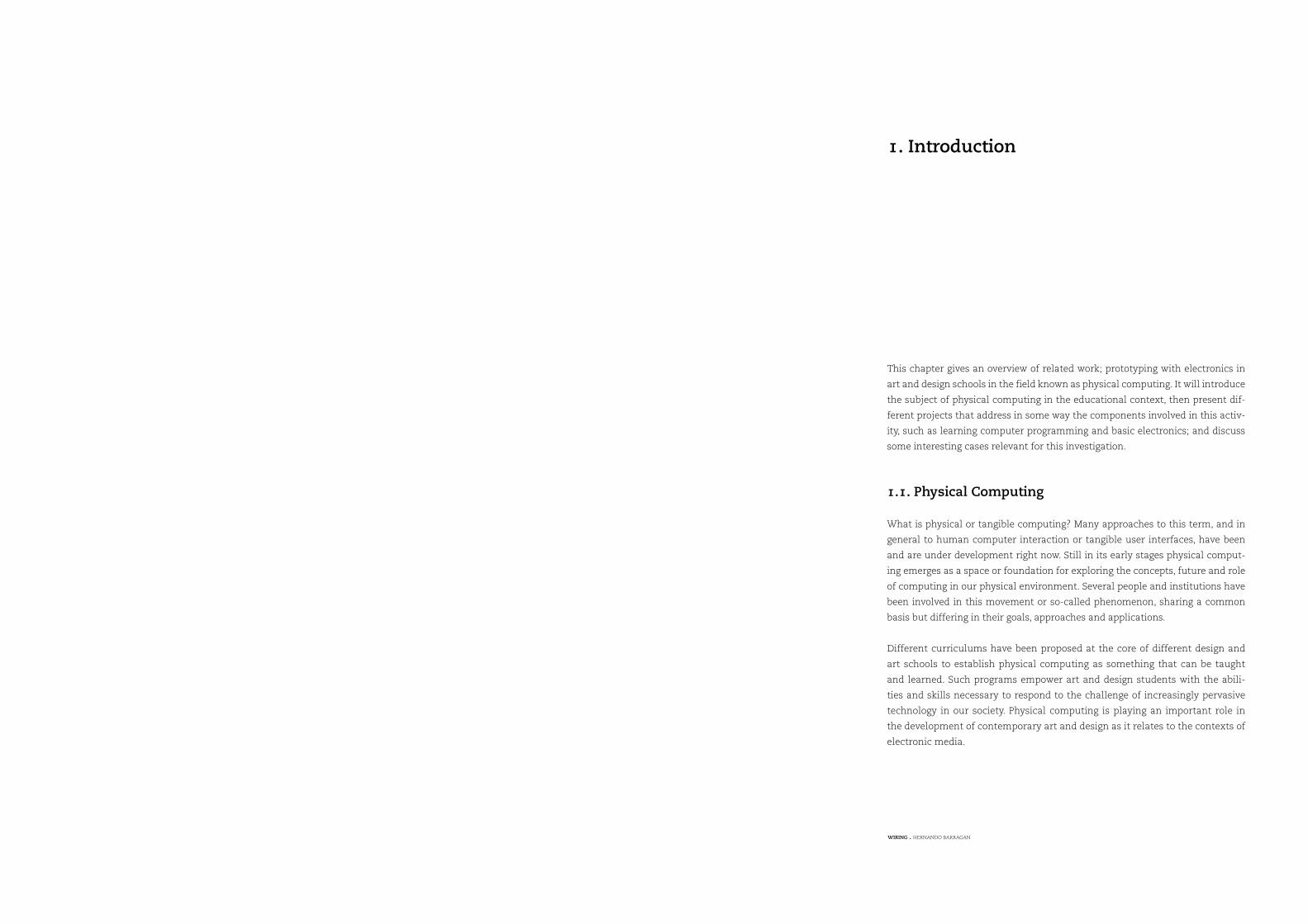
The microcontroller’s functionality varies from basic logic control up to fully
functioning computers with wireless Internet or network access, RF communica-
tion, Bluetooth, GPS capabilities, and more complex systems. Many companies
like Motorola, Microchip, Parallax, Texas Instruments, Rabbit Semiconductors,
ATMEL, UBICOM, Dallas Semiconductors etc. have a vast selection of program-
mable devices, and in some cases a single company offers hundreds of families
of microcontrollers.
40-Pins PIC Microcontroller
Microchip Inc.
1
18 WIRING . HERNANDO BARRAGAN
Signals can also be of analog nature. Many physical phenomena manifest in this
way, like measuring light intensity, temperature, sound or position, where there
is a range of intermediate values that can be measured. In this case a pin in a
microcontroller can be used as what is called an analog input or an analog-to-
digital converter (ADC). In an ADC a range of analog values is converted to a
range of numbers, depending on the precision of the ADC, for instance an 8-bit
precision ADC can differentiate between 256 possible values because that’s the
maximum decimal number that can be represented with 8 bits; others use 10-bit
precision for conversion, which can generate values between 0 and 1024. When
an analog pin reads 0 volts it returns a 0 and when it reads 5 volts, returns the
value 1024, with possibility of all the values in between the range: 2.5 volts re-
turns 512 and so on.
Microcontrollers also have analog outputs that work in a way very similar to
the analog inputs, but technically different. Usually the analog output is done
through a process called Pulse Width Modulation (PWM) that consists of generat-
ing a pulse train in a normal digital output. This is equivalent to turning the pin
ON and OFF very quickly, as it is done in dimmers for lamps or motor speed con-
trollers so the lamp or motor is not ON all the time but only part of it, reducing its
actual performance time. Real analog outputs can also be found; they are known
as a Digital-to-Analog Converter (DAC), again depending on the precision with
which they can convert a digital number into a voltage value on a physical pin.
There are audiences from diverse disciplines that are potentially in-terested in design, prototyping and programming in the context of electronic media, and would like a way that facilitates and encour-ages their process and allows them to test and come up with new ideas and possibilities. However, these audiences may not have the needed programming, electronics and math skills. A system oriented towards these audiences is needed, to allow programming and pro-totyping with electronics. Such a system needs to facilitate learning concepts that can be mapped and useful in different contexts.
Explained in a very simple way, a microcontroller is an electronic device with a
set of Input and Output pins. Physically these pins may look like real pins, or can
be just connectors of some kind that other devices can be plugged to, depending
on the microcontroller; there are some that are single units and others that are a
complete electronic board with access to the pins through connectors.
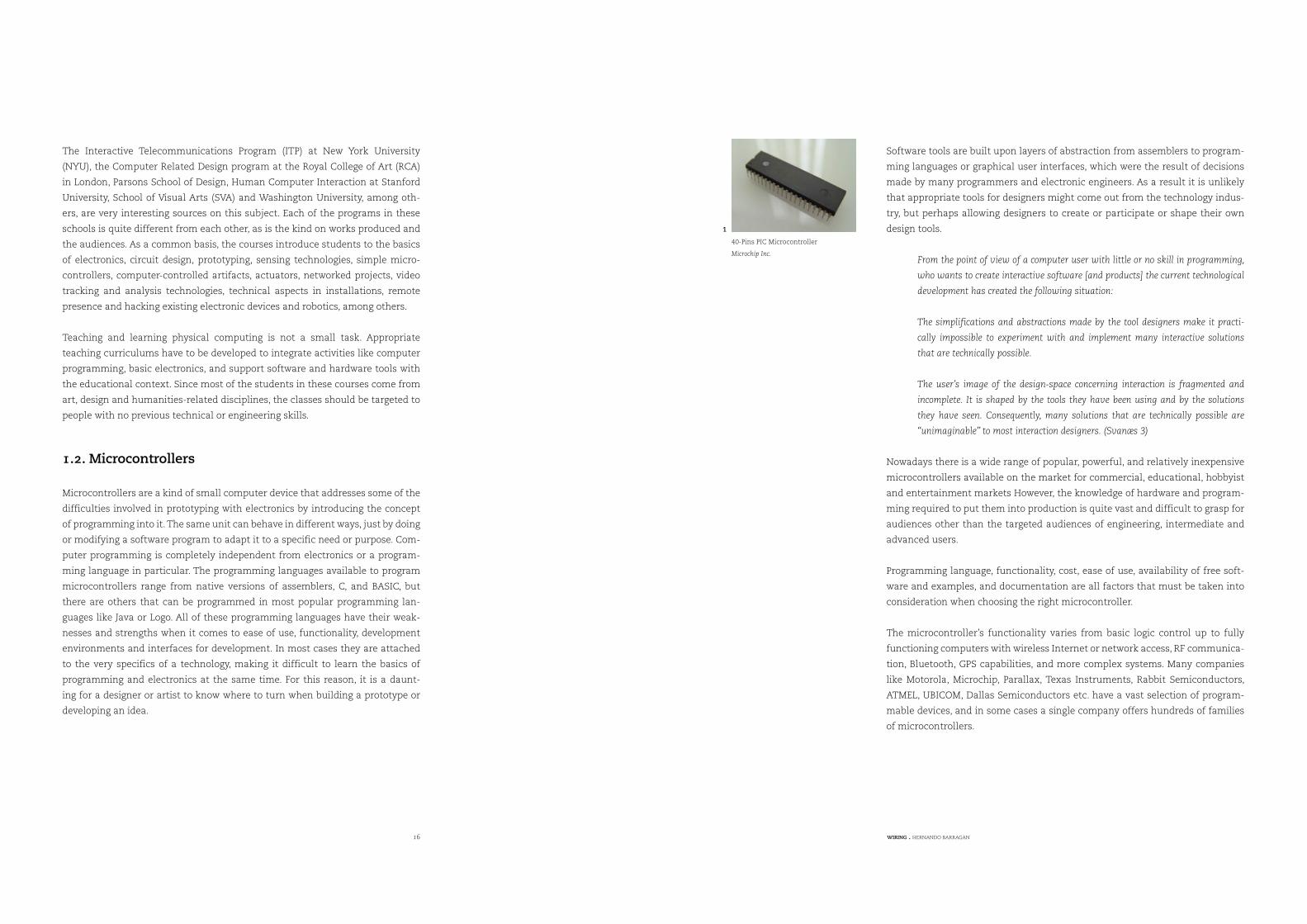
Depending on the microcontroller’s functionality, the pins can be inputs or out-
puts, so they can be used to receive and send signals. The signals can be discrete,
in the case of digital binary signals where the possible values are logical 0 (LOW)
or logical 1 (HIGH). These values (HIGH or LOW) are reflected in changes in volt-
age, let’s say LOW is 0 volts, and HIGH are 5 volts.
digitalRead(0)
digital I/O pin 0
HIGH
5-volt (HIGH signal)
digitalRead(0)
digital I/O pin 0
LOW
0-volt (LOW signal)
digitalWrite(0,HIGH)
digital I/O pin 0
5-volt (HIGH signal)
digitalWrite(0, LOW)
digital I/O pin 0
0-volt (LOW signal)
AVR atmega128 microcontrolelr
Atmel Corp.
2
80-Pin PIC Microcontroller
Microchip Inc.
3
Reading the value of a digital input pin.
4
Setting the value of a digital output pin
5
20 WIRING . HERNANDO BARRAGAN
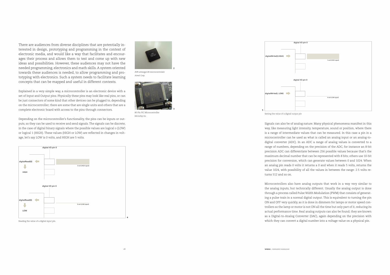
Some microcontrollers provide access to individual pins or to groups of pins at
the same time. Groups of pins are known as Ports. For example, an 8-bit port is a
set of 8 pins. The microcontroller provides functionality to write a value to a port,
and will set the values of the individual pins accordingly. This is useful to control
special kinds of devices or write data in parallel.
Microcontrollers also have timing abilities, usually a few timers that can be
used in different ways to measure time lapses, trigger events, synchronize func-
tions, etc.
Microcontrollers have communication capabilities, usually with serial ports, the
same kind of serial ports that are available in most computers. In this way they
can connect and communicate with other devices using the well-known serial
protocols. In many cases the serial ports are used for both programming the mi-
crocontroller and for communication purposes.
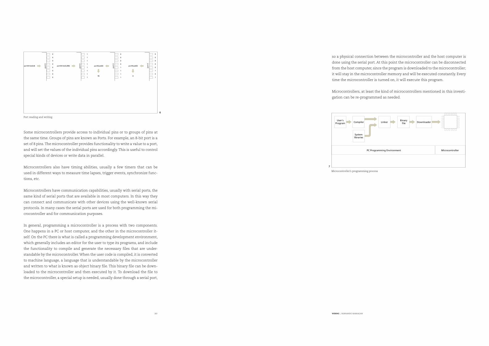
In general, programming a microcontroller is a process with two components.
One happens in a PC or host computer, and the other in the microcontroller it-
self. On the PC there is what is called a programming development environment,
which generally includes an editor for the user to type its programs, and include
the functionality to compile and generate the necessary files that are under-
standable by the microcontroller. When the user code is compiled, it is converted
to machine language, a language that is understandable by the microcontroller
and written to what is known as object binary file. This binary file can be down-
loaded to the microcontroller and then executed by it. To download the file to
the microcontroller, a special setup is needed, usually done through a serial port,
so a physical connection between the microcontroller and the host computer is
done using the serial port. At this point the microcontroller can be disconnected
from the host computer, since the program is downloaded to the microcontroller;
it will stay in the microcontroller memory and will be executed constantly. Every
time the microcontroller is turned on, it will execute this program.
Microcontrollers, at least the kind of microcontrollers mentioned in this investi-
gation can be re-programmed as needed.
portWrite(0,0)
0
0
0
0
0
0
0
0
portWrite(0,255)
1
1
1
1
1
1
1
1
portRead(0)
0
0
0
0
0
1
0
1
portRead(0)
0
0
0
0
1
1
1
115 3
po
rt0
po
rt0
po
rt0
po
rt0
User'sProgram
Systemlibraries
Compiler
MicrocontrollerPC Programming Environment
Linker DownloaderBinary
file
Port reading and writing
6
Microcontroller’s programming process
7
22 WIRING . HERNANDO BARRAGAN
DBN is not a general purpose programming language like C or Java, but was de-
signed to familiarize people with the basic concepts of computational media.
Sponsored by private institutions, Alan Kay and some colleagues developed
Squeak. It is a program designed for children to express ideas about math and
science, and to enhance children’s learning in these areas. Users can build com-
putational systems with it.
Boxer is under development at UC Berkeley by Andrea A. diSessa and Edward
H. Lay and some parts are copyrighted by MIT. It is a computational medium
based on a literacy model, including text and hypertext processing, dynamic and
interactive graphics, video, personal data management, (including e-mail and
networking) and programming.
The Visual Machine Model created in the MIT Media Laboratory at the Aesthetics
and Computation Group by Jared Shiffman, emphasizes the need for clear visual
representations of both machines and materials, and the importance of continu-
ity. It presents a new paradigm for the design of visual programming languages,
with the goal of making computation visible and, in turn, more accessible. Five
dynamic visual programming languages were designed and implemented ac-
cording to the specification of the Visual Machine Model. (Shiffman, 1999)
Processing, created by Ben Fry and Casey Reas of the Aesthetics + Computation
Group at the MIT Media Laboratory and Interaction Design Institute Ivrea is a
learning program and environment for creating systems in a subset of the JAVA
programming language, with real time three-dimensional graphics, color, input/
output and other features that DBN lacked.
The spirit of Processing is to act as an electronic sketchbook where people can
learn the fundamentals of computer programming within the context of the
electronic arts (Reas, 2003).
Both Design By Numbers, and Processing are systems that introduce the basic
ideas of computer programming within the context of visual design. Form ele-
ments are drawn using computational concepts like iteration, repetition, vari-
ables, and conditional statements, as well as structural elements like functions
and classes. They are powerful educational tools designed for adults, allowing
users to create programs that manifest mainly on the computer screen. With Pro-
cessing, users can create beautiful graphics that are interactive and dynamic.
Academic and private companies have created several software and hardware
systems for education, to provide a solution for teaching and learning computer
programming and prototyping with electronics. I will present a brief description
of some of these projects.
2.1. Learning computer programming
Logo was developed by a team from MIT, and was originally designed to intro-
duce children to programming concepts, to develop better thinking skills that
could be transferred to other contexts. Logo was supposed to be a language for
the teaching of mathematical ideas to children through computer programming.
It was intended to be easy to learn, easy to use, easy to read, but also powerful
and able to cope with complex problems. It was then discovered that Logo ex-
tended far beyond mathematical areas. The man who became the spokesperson
for this language was Seymour Papert.
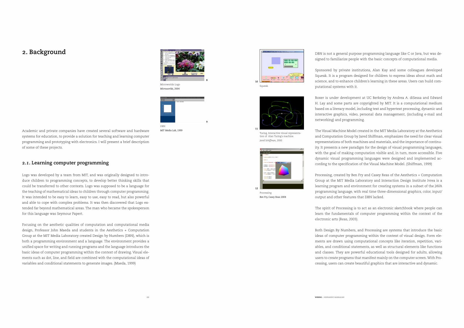
Focusing on the aesthetic qualities of computation and computational media
design, Professor John Maeda and students in the Aesthetics + Computation
Group at the MIT Media Laboratory created Design by Numbers (DBN), which is
both a programming environment and a language. The environment provides a
unified space for writing and running programs and the language introduces the
basic ideas of computer programming within the context of drawing. Visual ele-
ments such as dot, line, and field are combined with the computational ideas of
variables and conditional statements to generate images. (Maeda, 1999)
2. Background
Microworlds Logo
Microworlds, 2004
8
DBN
MIT Media Lab, 1999
9
Squeak.
10
Turing, Interactive visual representa-tion of Alan Turing’s machine.
Jared Schiffman, 2000
11
Processing
Ben Fry, Casey Reas 2004
12
24 WIRING . HERNANDO BARRAGAN
A number of workshops have been taught using Processing, refining methodolo-
gies and teaching curriculums, making the concepts of visuals and interaction to
emerge in the process of learning computer programming. WorkWorkshops also
facilitated the project’s communication, impact and further development.
2.2. Learning and prototyping with electronics
In the projects described above, the users learn the basics of computer program-
ming by creating applications that manifest on the screen, but can not extend
these concepts into the physical world, which is necessary to explore physical
interaction design and tangible media aspect. Most of the systems used in teach-
ing and learning physical computing were never intended for education. They
originated from the electronics and radio hobbyists, the robot design field and
robotics applications. These introduced the concept of “Kits”, semi-complete sets
that include basic electronic components as a common basis for beginners to
start their explorations.
To build and design robots, Professor Fred G. Martin at the MIT Media Laboratory,
designed several systems.
The Mini Board designed at MIT Media Laboratory by the Professor Martin and
his colleagues was a single board computer optimized for controlling small DC
motors and receiving data from various sensors, initially intended for control-
ling small mobile robots. It communicates with a desktop computer over a se-
rial port, making it suitable for desktop computer-based control as well. It was
designed in 1990, and since then several copies of the board were printed out
and distributed.
In 1989 Professor Martin designed the 6.270 Board which was very complex
board compared to the Mini Board. The project became a class called 6.270: The
MIT LEGO Robot Design Competition, intended for students to create fully au-
tonomous robots. This class is today a student-run activity where past students
become future organizers.
Students received a Kit containing LEGO parts, electronics, sensors, batteries,
motors and wire; they had a month to design, build and debug an autonomous
contest robot.
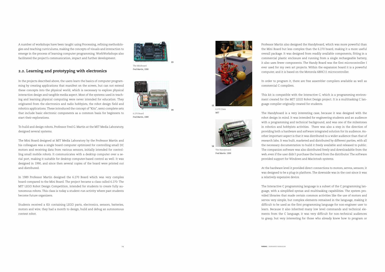
Professor Martin also designed the Handyboard, which was more powerful than
the Mini Board but less complex than the 6.270 board, making it a more useful
overall package. It was designed from readily available components, fitting in a
commercial plastic enclosure and running from a single rechargeable battery,
it also uses fewer components. The Handy Board was the first microcontroller I
ever used for my own art projects. Within the expansion board it is a powerful
computer, and it is based on the Motorola 68HC11 microcontroller.
In order to program it, there are free assembler compilers available as well as
commercial C compilers.
This kit is compatible with the Interactive C, which is a programming environ-
ment created for the MIT LEGO Robot Design project. It is a multitasking C lan-
guage compiler originally created for students.
The Handyboard is a very interesting case, because it was designed with the
robot design in mind. It was intended for engineering students and an audience
with a programming and technical background, and was one of the milestones
in robotics and hobbyists activities. There was also a step in the direction of
providing both a hardware and software integrated solution for its audience. An-
other important aspect is that it was distributed to a wider audience than that of
research labs. It was built, marketed and distributed by different parties, with all
the necessary documentation to build it freely available and released to public.
The companion software was also distributed freely and downloadable from the
web, even if the user didn’t purchase the board from the distributor. The software
provided support for Windows and Macintosh systems.
At the hardware level it provided direct connections to motors, servos, sensors; it
was designed to be a plug-in platform. The downside was in the cost since it was
a relatively expensive device.
The Interactive C programming language is a subset of the C programming lan-
guage, with a simplified syntax and multitasking capabilities. The system pro-
vided libraries that made certain common activities like the use of motors and
servos very simple, but complex elements remained in the language, making it
difficult to be used as the first programming language for non-engineer user to
learn. Because it also inherited many low level commands and technical ele-
ments from the C language, it was very difficult for non-technical audiences
to grasp, but very interesting for those who already knew how to program or
The Miniboard
Fred Martin, 1990
13
6.270 Board
Fred Martin, 1989
14 6.270 Class
MIT
15
The Handyboard
Fred Martin. 1999
16
26 WIRING . HERNANDO BARRAGAN
already knew C ,and didn’t want to go into the intricacies of low-level languages
like assembler.
The C programming language is the most widely used programming language
since it was devised in the 70s. After some years of development it was standard-
ized by the ANSI X3J11 committee. In the beginning it was associated with the
UNIX operating system, but later it expanded to all available systems becoming
the most spread programming language ever. Its abstractions lie in a sufficiently
high level that, with little effort, portability between machines can be achieved.
On the other hand the relationship between arrays and pointers, the way declara-
tion syntax mimics expression syntax, memory management and in general some
syntax particularities often serve as a stumbling block for beginners. Its success
lies in its portability, it remains as a simple and small language. It was created as
a tool to make useful programs that do useful things, covering the needs of many
programmers without trying to supply too much things. It displaced languages
like assembler while maintaining an abstraction level of machines and fluent
enough to describe algorithms and interactions in a wide range of environments.
(D. Ritchie 1993)
People at the Lifelong Kindergarten Group (LLK) at the MIT Media Laboratory are
working on the development of educational tools for learning concepts about
hardware and computation. Over the past decade, LLK worked on the develop-
ment of Programmable Bricks.
The Programmable Brick is a tiny portable computer embedded into a LEGO
brick for kids to build into their LEGO systems. Kids can create robots or stand-
alone projects, not only structures and mechanisms, but also behaviors. The aim
is to teach kids concepts about engineering design and technology by bringing
computation to their physical environment. Programmable Bricks have expand-
ed into two areas. On the commercial side, they evolved into something called
the RCX Brick that became the foundation for LEGO Mindstorms, a commercially
available set of toys that lets users build robots and computational projects us-
ing LEGO blocks.
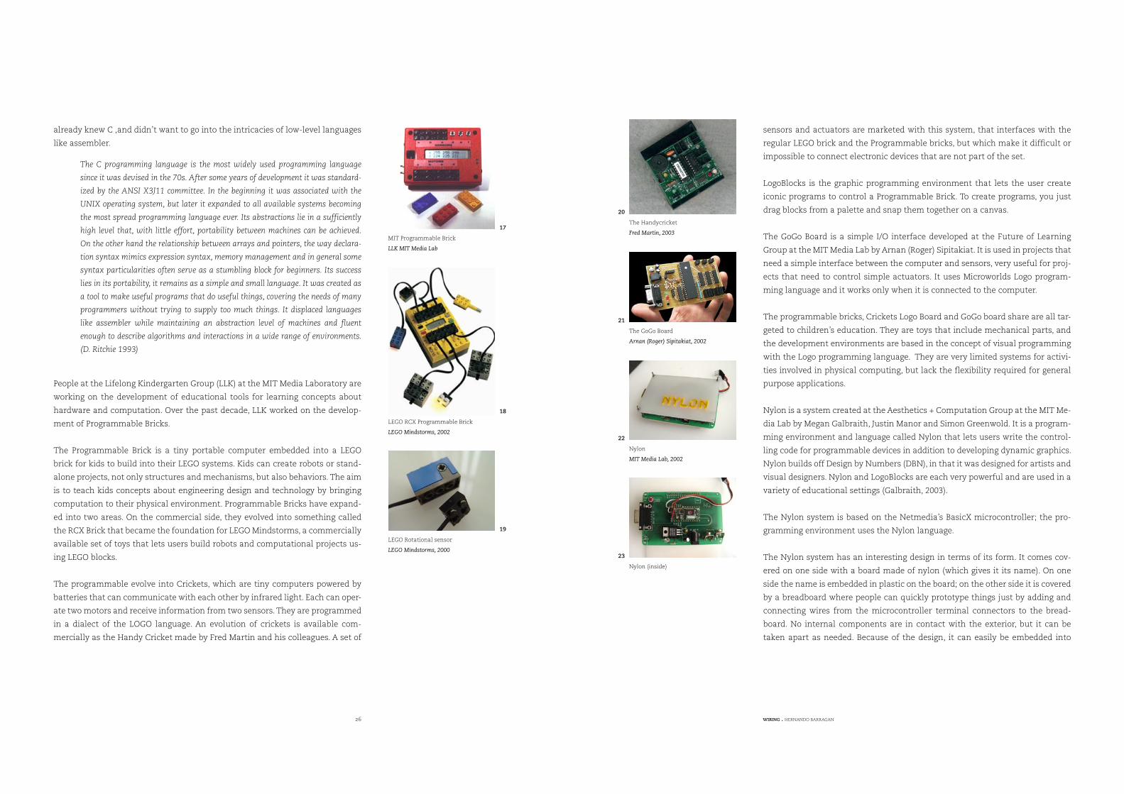
The programmable evolve into Crickets, which are tiny computers powered by
batteries that can communicate with each other by infrared light. Each can oper-
ate two motors and receive information from two sensors. They are programmed
in a dialect of the LOGO language. An evolution of crickets is available com-
mercially as the Handy Cricket made by Fred Martin and his colleagues. A set of
sensors and actuators are marketed with this system, that interfaces with the
regular LEGO brick and the Programmable bricks, but which make it difficult or
impossible to connect electronic devices that are not part of the set.
LogoBlocks is the graphic programming environment that lets the user create
iconic programs to control a Programmable Brick. To create programs, you just
drag blocks from a palette and snap them together on a canvas.
The GoGo Board is a simple I/O interface developed at the Future of Learning
Group at the MIT Media Lab by Arnan (Roger) Sipitakiat. It is used in projects that
need a simple interface between the computer and sensors, very useful for proj-
ects that need to control simple actuators. It uses Microworlds Logo program-
ming language and it works only when it is connected to the computer.
The programmable bricks, Crickets Logo Board and GoGo board share are all tar-
geted to children’s education. They are toys that include mechanical parts, and
the development environments are based in the concept of visual programming
with the Logo programming language. They are very limited systems for activi-
ties involved in physical computing, but lack the flexibility required for general
purpose applications.
Nylon is a system created at the Aesthetics + Computation Group at the MIT Me-
dia Lab by Megan Galbraith, Justin Manor and Simon Greenwold. It is a program-
ming environment and language called Nylon that lets users write the control-
ling code for programmable devices in addition to developing dynamic graphics.
Nylon builds off Design by Numbers (DBN), in that it was designed for artists and
visual designers. Nylon and LogoBlocks are each very powerful and are used in a
variety of educational settings (Galbraith, 2003).
The Nylon system is based on the Netmedia’s BasicX microcontroller; the pro-
gramming environment uses the Nylon language.
The Nylon system has an interesting design in terms of its form. It comes cov-
ered on one side with a board made of nylon (which gives it its name). On one
side the name is embedded in plastic on the board; on the other side it is covered
by a breadboard where people can quickly prototype things just by adding and
connecting wires from the microcontroller terminal connectors to the bread-
board. No internal components are in contact with the exterior, but it can be
taken apart as needed. Because of the design, it can easily be embedded into
22. Nylon
MIT Media Lab, 2002
MIT Programmable Brick
LLK MIT Media Lab
17
LEGO RCX Programmable Brick
LEGO Mindstorms, 2002
18
LEGO Rotational sensor
LEGO Mindstorms, 2000
19
The Handycricket
Fred Martin, 2003
20
The GoGo Board
Arnan (Roger) Sipitakiat, 2002
21
Nylon
MIT Media Lab, 2002
22
Nylon (inside)
23
28 WIRING . HERNANDO BARRAGAN
different things, like clothes, pockets etc. making it an interesting option for dif-
ferent prototyping situations. It also has a battery connector inside, so a 9-volt
battery can be plugged inside the package with no extra or bulky space needed.
The model is very interesting as it is a clear attempt to make a self-contained
unit for both programming and prototyping with electronics, which comes close
to being true desirable environment for a school. The programming environment
offered support exclusively for the windows operating system. Internally the
Nylon language was translated into Netmedia’s flavor of the BASIC language
and then downloaded to the device using the proprietary BasicX programming
tools which are only available for the Windows operating system. This limited
the possibilities for expansion for the Nylon language and the system itself, as
well as the possibilities for further distribution. Because it was mostly targeted
to create graphic applications within the Hotpants device, the Nylon program-
ming language included commands for drawing basic form elements like lines,
dots, circles, etc.
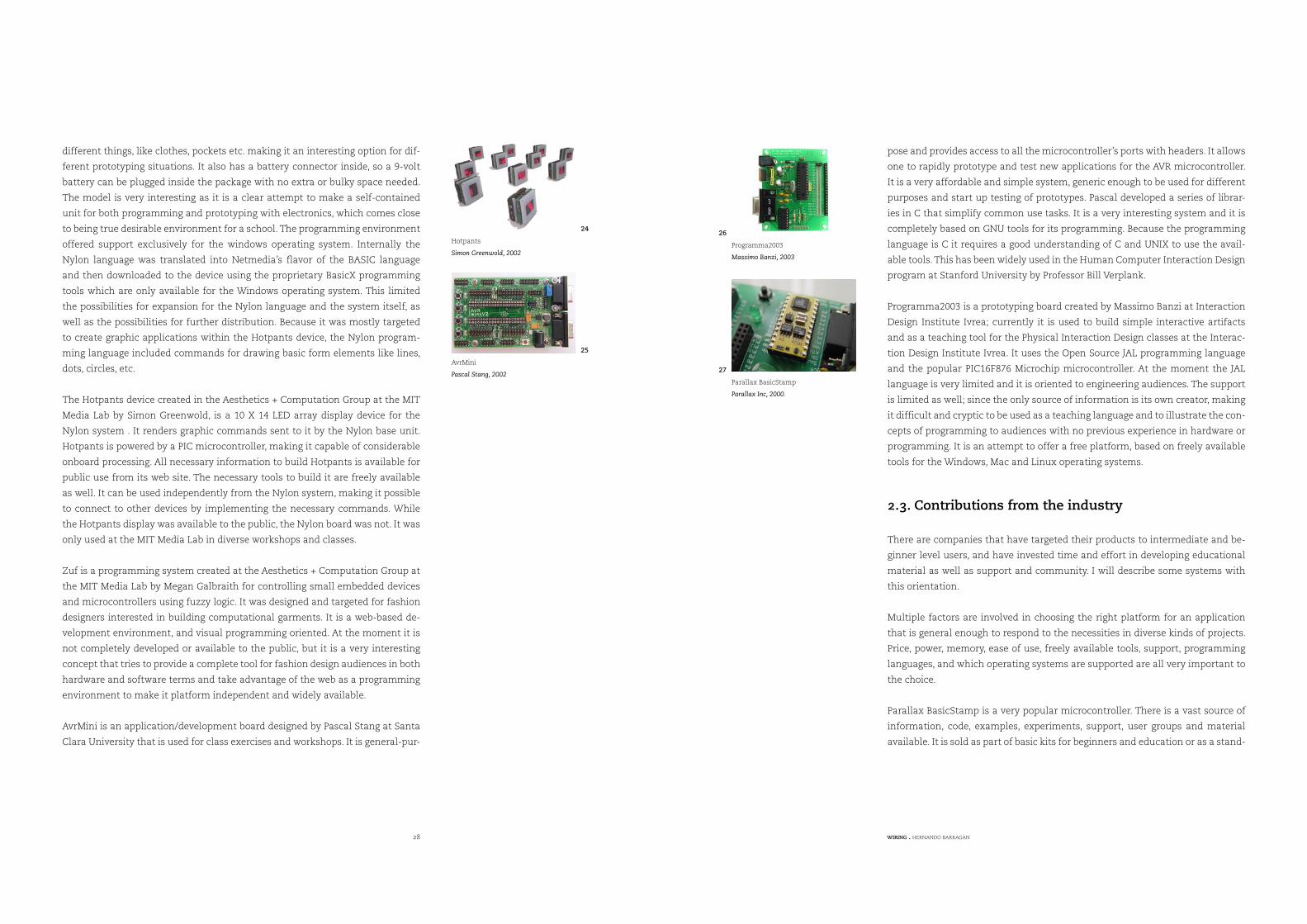
The Hotpants device created in the Aesthetics + Computation Group at the MIT
Media Lab by Simon Greenwold, is a 10 X 14 LED array display device for the
Nylon system . It renders graphic commands sent to it by the Nylon base unit.
Hotpants is powered by a PIC microcontroller, making it capable of considerable
onboard processing. All necessary information to build Hotpants is available for
public use from its web site. The necessary tools to build it are freely available
as well. It can be used independently from the Nylon system, making it possible
to connect to other devices by implementing the necessary commands. While
the Hotpants display was available to the public, the Nylon board was not. It was
only used at the MIT Media Lab in diverse workshops and classes.
Zuf is a programming system created at the Aesthetics + Computation Group at
the MIT Media Lab by Megan Galbraith for controlling small embedded devices
and microcontrollers using fuzzy logic. It was designed and targeted for fashion
designers interested in building computational garments. It is a web-based de-
velopment environment, and visual programming oriented. At the moment it is
not completely developed or available to the public, but it is a very interesting
concept that tries to provide a complete tool for fashion design audiences in both
hardware and software terms and take advantage of the web as a programming
environment to make it platform independent and widely available.
AvrMini is an application/development board designed by Pascal Stang at Santa
Clara University that is used for class exercises and workshops. It is general-pur-
pose and provides access to all the microcontroller’s ports with headers. It allows
one to rapidly prototype and test new applications for the AVR microcontroller.
It is a very affordable and simple system, generic enough to be used for different
purposes and start up testing of prototypes. Pascal developed a series of librar-
ies in C that simplify common use tasks. It is a very interesting system and it is
completely based on GNU tools for its programming. Because the programming
language is C it requires a good understanding of C and UNIX to use the avail-
able tools. This has been widely used in the Human Computer Interaction Design
program at Stanford University by Professor Bill Verplank.
Programma2003 is a prototyping board created by Massimo Banzi at Interaction
Design Institute Ivrea; currently it is used to build simple interactive artifacts
and as a teaching tool for the Physical Interaction Design classes at the Interac-
tion Design Institute Ivrea. It uses the Open Source JAL programming language
and the popular PIC16F876 Microchip microcontroller. At the moment the JAL
language is very limited and it is oriented to engineering audiences. The support
is limited as well; since the only source of information is its own creator, making
it difficult and cryptic to be used as a teaching language and to illustrate the con-
cepts of programming to audiences with no previous experience in hardware or
programming. It is an attempt to offer a free platform, based on freely available
tools for the Windows, Mac and Linux operating systems.
2.3. Contributions from the industry
There are companies that have targeted their products to intermediate and be-
ginner level users, and have invested time and effort in developing educational
material as well as support and community. I will describe some systems with
this orientation.
Multiple factors are involved in choosing the right platform for an application
that is general enough to respond to the necessities in diverse kinds of projects.
Price, power, memory, ease of use, freely available tools, support, programming
languages, and which operating systems are supported are all very important to
the choice.
Parallax BasicStamp is a very popular microcontroller. There is a vast source of
information, code, examples, experiments, support, user groups and material
available. It is sold as part of basic kits for beginners and education or as a stand-
Hotpants
Simon Greenwold, 2002
24
AvrMini
Pascal Stang, 2002
25
Programma2003
Massimo Banzi, 2003
26
Parallax BasicStamp
Parallax Inc, 2000.
27
30 WIRING . HERNANDO BARRAGAN
alone product for experienced users as well. The kits include a board, microcon-
troller, sensors, motors, and complementary electronic devices and companion
book to develop experiments.
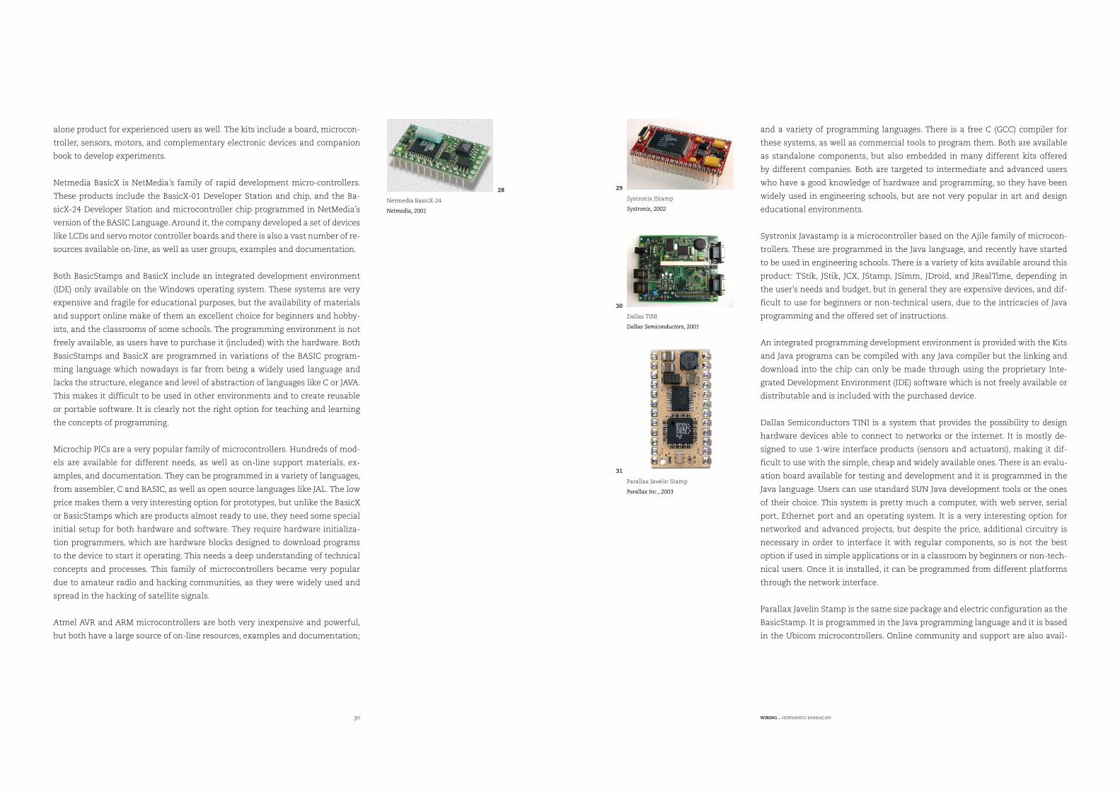
Netmedia BasicX is NetMedia’s family of rapid development micro-controllers.
These products include the BasicX-01 Developer Station and chip, and the Ba-
sicX-24 Developer Station and microcontroller chip programmed in NetMedia’s
version of the BASIC Language. Around it, the company developed a set of devices
like LCDs and servo motor controller boards and there is also a vast number of re-
sources available on-line, as well as user groups, examples and documentation.
Both BasicStamps and BasicX include an integrated development environment
(IDE) only available on the Windows operating system. These systems are very
expensive and fragile for educational purposes, but the availability of materials
and support online make of them an excellent choice for beginners and hobby-
ists, and the classrooms of some schools. The programming environment is not
freely available, as users have to purchase it (included) with the hardware. Both
BasicStamps and BasicX are programmed in variations of the BASIC program-
ming language which nowadays is far from being a widely used language and
lacks the structure, elegance and level of abstraction of languages like C or JAVA.
This makes it difficult to be used in other environments and to create reusable
or portable software. It is clearly not the right option for teaching and learning
the concepts of programming.
Microchip PICs are a very popular family of microcontrollers. Hundreds of mod-
els are available for different needs, as well as on-line support materials, ex-
amples, and documentation. They can be programmed in a variety of languages,
from assembler, C and BASIC, as well as open source languages like JAL. The low
price makes them a very interesting option for prototypes, but unlike the BasicX
or BasicStamps which are products almost ready to use, they need some special
initial setup for both hardware and software. They require hardware initializa-
tion programmers, which are hardware blocks designed to download programs
to the device to start it operating. This needs a deep understanding of technical
concepts and processes. This family of microcontrollers became very popular
due to amateur radio and hacking communities, as they were widely used and
spread in the hacking of satellite signals.
Atmel AVR and ARM microcontrollers are both very inexpensive and powerful,
but both have a large source of on-line resources, examples and documentation;
and a variety of programming languages. There is a free C (GCC) compiler for
these systems, as well as commercial tools to program them. Both are available
as standalone components, but also embedded in many different kits offered
by different companies. Both are targeted to intermediate and advanced users
who have a good knowledge of hardware and programming, so they have been
widely used in engineering schools, but are not very popular in art and design
educational environments.
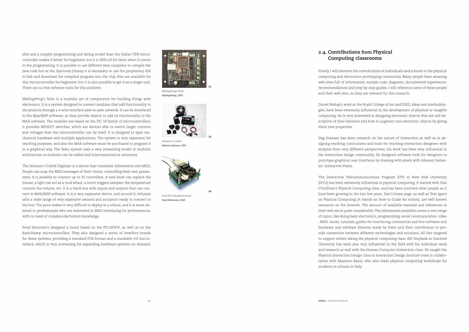
Systronix Javastamp is a microcontroller based on the Ajile family of microcon-
trollers. These are programmed in the Java language, and recently have started
to be used in engineering schools. There is a variety of kits available around this
product: TStik, JStik, JCX, JStamp, JSimm, JDroid, and JRealTime, depending in
the user’s needs and budget, but in general they are expensive devices, and dif-
ficult to use for beginners or non-technical users, due to the intricacies of Java
programming and the offered set of instructions.
An integrated programming development environment is provided with the Kits
and Java programs can be compiled with any Java compiler but the linking and
download into the chip can only be made through using the proprietary Inte-
grated Development Environment (IDE) software which is not freely available or
distributable and is included with the purchased device.
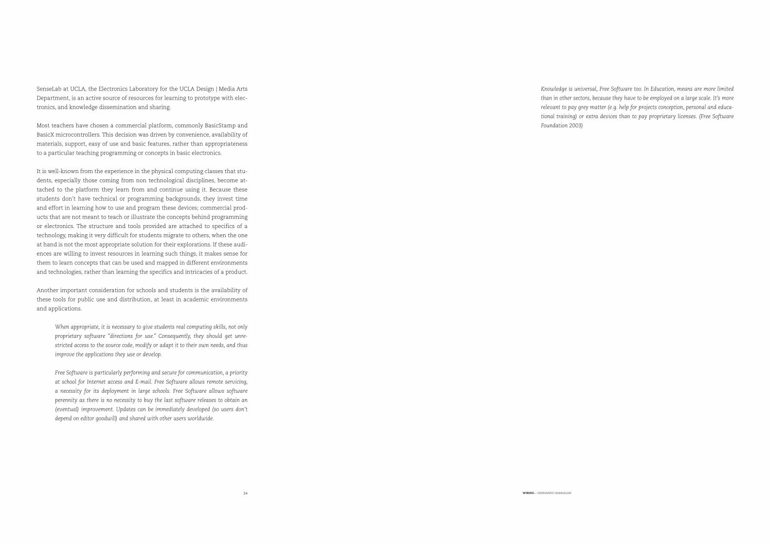
Dallas Semiconductors TINI is a system that provides the possibility to design
hardware devices able to connect to networks or the internet. It is mostly de-
signed to use 1-wire interface products (sensors and actuators), making it dif-
ficult to use with the simple, cheap and widely available ones. There is an evalu-
ation board available for testing and development and it is programmed in the
Java language. Users can use standard SUN Java development tools or the ones
of their choice. This system is pretty much a computer, with web server, serial
port, Ethernet port and an operating system. It is a very interesting option for
networked and advanced projects, but despite the price, additional circuitry is
necessary in order to interface it with regular components, so is not the best
option if used in simple applications or in a classroom by beginners or non-tech-
nical users. Once it is installed, it can be programmed from different platforms
through the network interface.
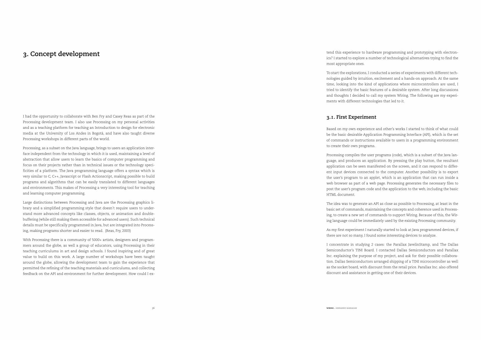
Parallax Javelin Stamp is the same size package and electric configuration as the
BasicStamp. It is programmed in the Java programming language and it is based
in the Ubicom microcontrollers. Online community and support are also avail-
Netmedia BasicX-24
Netmedia, 2001
28
Systronix JStamp
Systronix, 2002
29
Dallas TINI
Dallas Semiconductors, 2001
30
Parallax Javelin Stamp
Parallax Inc., 2003
31
32 WIRING . HERNANDO BARRAGAN
able and a simpler programming and wiring model than the Dallas TINI micro-
controller makes it better for beginners, but it is difficult for them when it comes
to the programming. It is possible to use different Java compilers to compile the
Java code but as the Systronix JStamp it is necessary to use the proprietary IDE
to link and download the compiled program into the chip. Kits are available for
this microcontroller for beginners, but it is also possible to get it as a single unit.
There are no free software tools for this platform.
Makingthing’s Teleo is a modular set of components for building things with
electronics. It is a system designed to connect modules that add functionality to
the projects through a 4-wire interface peer-to-peer network. It can be interfaced
to the Max/MSP software, as they provide objects to add its functionality to the
MAX software. The modules are based on the PIC 18 family of microcontrollers;
it provides MOSFET switches, which are devices able to switch larger currents
and voltages than the microcontroller can by itself. It is designed to span me-
chanical hardware and multiple applications. The system is very expensive for
teaching purposes, and also the MAX software must be purchased to program it
in a graphical way. The Teleo system uses a very interesting model of modular
architecture so modules can be added and interconnected as necessary.
The Infusion I-CubeX Digitizer is a device that translates information into MIDI.
People can map the MIDI messages of their choice, controlling their own param-
eters. It is possible to connect up to 32 controllers. A turn knob can replace the
mouse, a light can act as a mod wheel, a touch triggers samples, the temperature
controls the volume, etc. It is a black box with inputs and outputs that can con-
nect to MAX/MSP software. It is a very expensive device, and around it, Infusion
sells a wide range of very expensive sensors and actuators ready to connect to
the box. The price makes it very difficult to deploy in a school, and it is more ori-
ented to professionals who are interested in MIDI interfacing for performances,
with no need of complex electronics knowledge.
Pond Electronics designed a board based on the PIC16F876, as well as on the
BasicStamp microcontrollers. They also designed a series of interface boards
for these systems, providing a standard PCB format and a stackable I/O bus in-
terface, which is very interesting for expanding hardware systems on demand.
2.4. Contributions from Physical
Finally I will mention the contributions of individuals and schools to the physical
computing and electronics prototyping community. Many people have amazing
web sites full of information, sample code, diagrams, documented experiences,
recommendations and step-by-step guides. I will reference some of these people
and their web sites, as they are relevant for this research.
Durrel Bishop’s work at the Royal College of Art and IDEO, ideas and methodolo-
gies, have been extremely influential in the development of physical or tangible
computing. He is very interested in designing electronic objects that are self-de-
scriptive of their behavior and how to augment non-electronic objects by giving
them new properties.
Dag Svanaes has done research on the nature of interaction as well as in de-
signing teaching curriculums and tools for teaching interaction designers with
analysis from very different perspectives; his work has been very influential in
the interaction design community. He designed software tools for designers to
prototype graphical user interfaces by drawing with pixels with inherent behav-
ior: Interactive Pixels.
The Interactive Telecommunications Program (ITP) at New York University
(NYU) has been extremely influential in physical computing. It started with Dan
O’Sullivan’s Physical Computing class, and has been involved other people as it
have been growing in the last few years. Dan’s home page, as well as Tom Igoe’s
on Physical Computing (A Hands-on How-to Guide for Artists), are well known
resources on the internet. The amount of available material and references in
their web site is quite considerable. The information available covers a vast range
of topics, like doing basic electronics, programming, serial communication, video
, MIDI, hacks, tutorials, guides for interfacing commercial and free software and
hardware and software libraries made by them and their contributors to pro-
vide connection between different technologies and solutions. All this targeted
to support artists taking the physical computing class. Bill Verplank at Stanford
University has been also very influential in the field with his individual work
and research as well with the Human Computer Interaction class. He taught the
Physical Interaction Design class at Interaction Design Institute Ivrea in collabo-
ration with Massimo Banzi, who also leads physical computing workshops for
students in schools in Italy.
Computing classrooms
Makingthings Teleo
Makingthings, 2003
32
Infusion I-CubeX
Infusion Systems, 2001
33
Pond PIC Ultraflash Board
Pond Electronics, 2003
34
34 WIRING . HERNANDO BARRAGAN
SenseLab at UCLA, the Electronics Laboratory for the UCLA Design | Media Arts
Department, is an active source of resources for learning to prototype with elec-
tronics, and knowledge dissemination and sharing.
Most teachers have chosen a commercial platform, commonly BasicStamp and
BasicX microcontrollers. This decision was driven by convenience, availability of
materials, support, easy of use and basic features, rather than appropriateness
to a particular teaching programming or concepts in basic electronics.
It is well-known from the experience in the physical computing classes that stu-
dents, especially those coming from non technological disciplines, become at-
tached to the platform they learn from and continue using it. Because these
students don’t have technical or programming backgrounds, they invest time
and effort in learning how to use and program these devices; commercial prod-
ucts that are not meant to teach or illustrate the concepts behind programming
or electronics. The structure and tools provided are attached to specifics of a
technology, making it very difficult for students migrate to others, when the one
at hand is not the most appropriate solution for their explorations. If these audi-
ences are willing to invest resources in learning such things, it makes sense for
them to learn concepts that can be used and mapped in different environments
and technologies, rather than learning the specifics and intricacies of a product.
Another important consideration for schools and students is the availability of
these tools for public use and distribution, at least in academic environments
and applications.
When appropriate, it is necessary to give students real computing skills, not only
proprietary software “directions for use.” Consequently, they should get unre-
stricted access to the source code, modify or adapt it to their own needs, and thus
improve the applications they use or develop.
Free Software is particularly performing and secure for communication, a priority
at school for Internet access and E-mail. Free Software allows remote servicing,
a necessity for its deployment in large schools. Free Software allows software
perennity as there is no necessity to buy the last software releases to obtain an
(eventual) improvement. Updates can be immediately developed (so users don’t
depend on editor goodwill) and shared with other users worldwide.
Knowledge is universal, Free Software too. In Education, means are more limited
than in other sectors, because they have to be employed on a large scale. It’s more
relevant to pay grey matter (e.g. help for projects conception, personal and educa-
tional training) or extra devices than to pay proprietary licenses. (Free Software
Foundation 2003)
36 WIRING . HERNANDO BARRAGAN
3. Concept development
I had the opportunity to collaborate with Ben Fry and Casey Reas as part of the
Processing development team. I also use Processing on my personal activities
and as a teaching platform for teaching an Introduction to design for electronic
media at the University of Los Andes in Bogotá, and have also taught diverse
Processing workshops in different parts of the world.
Processing, as a subset on the Java language, brings to users an application inter-
face independent from the technology in which it is used, maintaining a level of
abstraction that allow users to learn the basics of computer programming and
focus on their projects rather than in technical issues or the technology speci-
ficities of a platform. The Java programming language offers a syntax which is
very similar to C, C++, Javascript or Flash Actionscript, making possible to build
programs and algorithms that can be easily translated to different languages
and environments. This makes of Processing a very interesting tool for teaching
and learning computer programming.
Large distinctions between Processing and Java are the Processing graphics li-
brary and a simplified programming style that doesn’t require users to under-
stand more advanced concepts like classes, objects, or animation and double-
buffering (while still making them accessible for advanced users). Such technical
details must be specifically programmed in Java, but are integrated into Process-
ing, making programs shorter and easier to read. (Reas, Fry, 2003)
With Processing there is a community of 5000+ artists, designers and program-
mers around the globe, as well a group of educators, using Processing in their
teaching curriculums in art and design schools. I found inspiring and of great
value to build on this work. A large number of workshops have been taught
around the globe, allowing the development team to gain the experience that
permitted the refining of the teaching materials and curriculums, and collecting
feedback on the API and environment for further development. How could I ex-
tend this experience to hardware programming and prototyping with electron-
ics? I started to explore a number of technological alternatives trying to find the
most appropriate ones.
To start the explorations, I conducted a series of experiments with different tech-
nologies guided by intuition, excitement and a hands-on approach. At the same
time, looking into the kind of applications where microcontrollers are used, I
tried to identify the basic features of a desirable system. After long discussions
and thoughts I decided to call my system Wiring. The following are my experi-
ments with different technologies that led to it.
3.1. First Experiment
Based on my own experience and other’s works I started to think of what could
be the basic desirable Application Programming Interface (API), which is the set
of commands or instructions available to users in a programming environment
to create their own programs.
Processing compiles the user programs (code), which is a subset of the Java lan-
guage, and produces an application. By pressing the play button, the resultant
application can be seen manifested on the screen, and it can respond to differ-
ent input devices connected to the computer. Another possibility is to export
the user’s program to an applet, which is an application that can run inside a
web browser as part of a web page. Processing generates the necessary files to
post the user’s program code and the application to the web, including the basic
HTML document.
The idea was to generate an API as close as possible to Processing, at least in the
basic set of commands, maintaining the concepts and coherence used in Process-
ing, to create a new set of commands to support Wiring. Because of this, the Wir-
ing language could be immediately used by the existing Processing community.
As my first experiment I naturally started to look at Java programmed devices, if
there are not so many, I found some interesting devices to analyze.
I concentrate in studying 2 cases: the Parallax JavelinStamp, and The Dallas
Semiconductor’s TINI Board. I contacted Dallas Semiconductors and Parallax
Inc. explaining the purpose of my project, and ask for their possible collabora-
tion. Dallas Semiconductors arranged shipping of a TINI microcontroller as well
as the socket board, with discount from the retail price. Parallax Inc. also offered
discount and assistance in getting one of their devices.
38 WIRING . HERNANDO BARRAGAN
As a technology enthusiast I found the Dallas TINI board very interesting, its
capabilities to connect to the network are quite amazing. It is a very powerful
microcontroller, almost a small computer. Users can run a web server, and can
also connect to it from the network; it can also be connected to the computer’s
serial port. Once it is up and running, the users can modify their programs and
then they can be sent to the board via FTP.
The board is mostly designed to be interfaced with one-wire devices, which are
a set of sensors and actuators that operate with literally one-wire connection
and use a special protocol for that—but I found that connecting an LED and to
make it blink is quite difficult—and this usually is the first exercise for interac-
tion design students.
The TINI microcontroller has a Java API very similar to the standard Java, with
additional instructions to support its functionality. It uses standard Java classes,
which are basically the Java compiled files and then these are linked into a bi-
nary file that can be uploaded into the board. Programmers can use the Java
compiler of their choice to compile their programs, but the linking is achieved
through the Dallas tools.
It is very difficult to use as a platform for teaching physical interaction design.
The SIMM and the board are quite big and expensive even before the user’s cir-
cuitry is added for creating a prototype, but no doubt they are very interesting
hardware for advanced or very specific purposes.
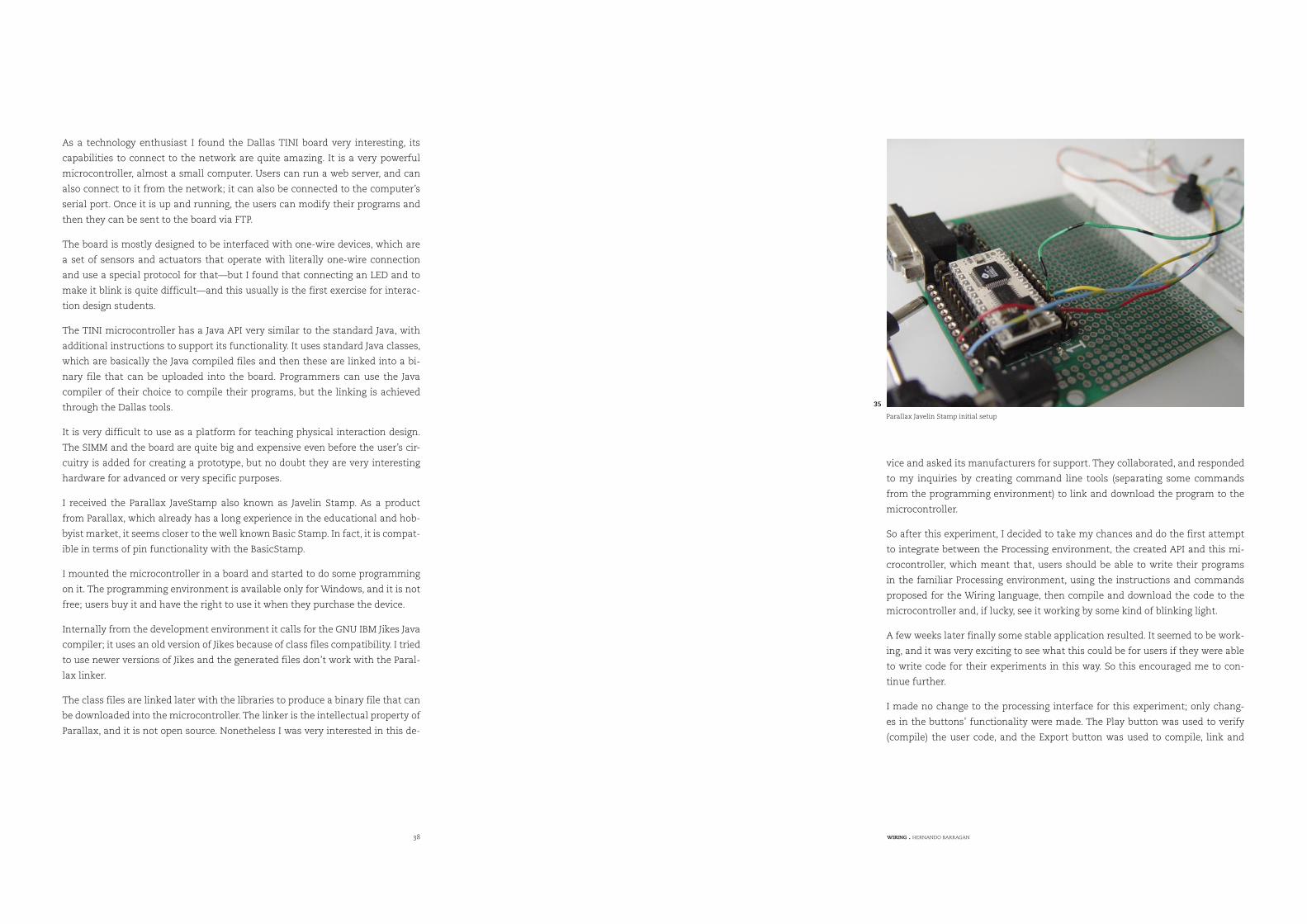
I received the Parallax JaveStamp also known as Javelin Stamp. As a product
from Parallax, which already has a long experience in the educational and hob-
byist market, it seems closer to the well known Basic Stamp. In fact, it is compat-
ible in terms of pin functionality with the BasicStamp.
I mounted the microcontroller in a board and started to do some programming
on it. The programming environment is available only for Windows, and it is not
free; users buy it and have the right to use it when they purchase the device.
Internally from the development environment it calls for the GNU IBM Jikes Java
compiler; it uses an old version of Jikes because of class files compatibility. I tried
to use newer versions of Jikes and the generated files don’t work with the Paral-
lax linker.
The class files are linked later with the libraries to produce a binary file that can
be downloaded into the microcontroller. The linker is the intellectual property of
Parallax, and it is not open source. Nonetheless I was very interested in this de-
vice and asked its manufacturers for support. They collaborated, and responded
to my inquiries by creating command line tools (separating some commands
from the programming environment) to link and download the program to the
microcontroller.
So after this experiment, I decided to take my chances and do the first attempt
to integrate between the Processing environment, the created API and this mi-
crocontroller, which meant that, users should be able to write their programs
in the familiar Processing environment, using the instructions and commands
proposed for the Wiring language, then compile and download the code to the
microcontroller and, if lucky, see it working by some kind of blinking light.
A few weeks later finally some stable application resulted. It seemed to be work-
ing, and it was very exciting to see what this could be for users if they were able
to write code for their experiments in this way. So this encouraged me to con-
tinue further.
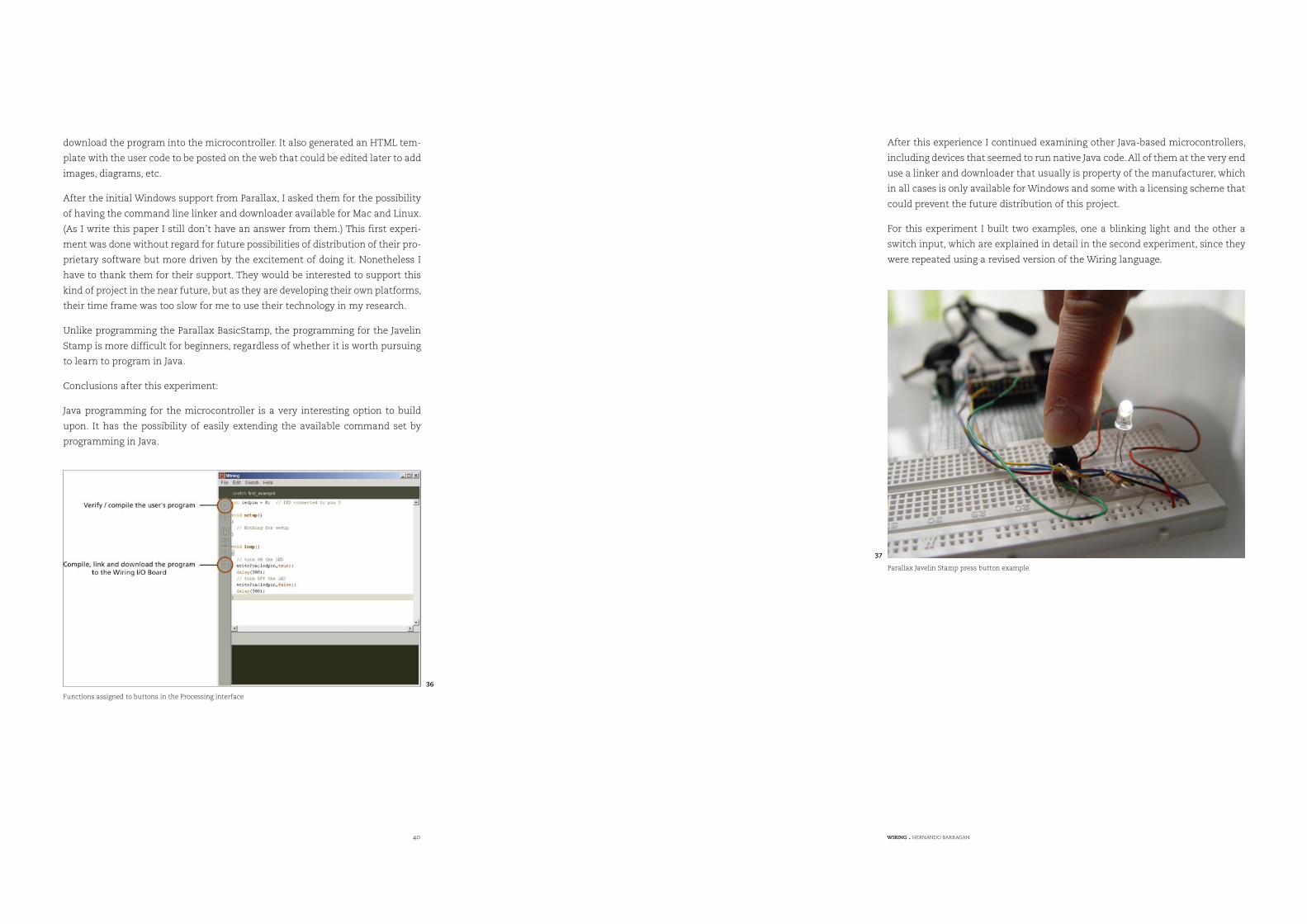
I made no change to the processing interface for this experiment; only chang-
es in the buttons’ functionality were made. The Play button was used to verify
(compile) the user code, and the Export button was used to compile, link and
Parallax Javelin Stamp initial setup
35
40 WIRING . HERNANDO BARRAGAN
download the program into the microcontroller. It also generated an HTML tem-
plate with the user code to be posted on the web that could be edited later to add
images, diagrams, etc.
After the initial Windows support from Parallax, I asked them for the possibility
of having the command line linker and downloader available for Mac and Linux.
(As I write this paper I still don’t have an answer from them.) This first experi-
ment was done without regard for future possibilities of distribution of their pro-
prietary software but more driven by the excitement of doing it. Nonetheless I
have to thank them for their support. They would be interested to support this
kind of project in the near future, but as they are developing their own platforms,
their time frame was too slow for me to use their technology in my research.
Unlike programming the Parallax BasicStamp, the programming for the Javelin
Stamp is more difficult for beginners, regardless of whether it is worth pursuing
to learn to program in Java.
Conclusions after this experiment:
Java programming for the microcontroller is a very interesting option to build
upon. It has the possibility of easily extending the available command set by
programming in Java.
After this experience I continued examining other Java-based microcontrollers,
including devices that seemed to run native Java code. All of them at the very end
use a linker and downloader that usually is property of the manufacturer, which
in all cases is only available for Windows and some with a licensing scheme that
could prevent the future distribution of this project.
For this experiment I built two examples, one a blinking light and the other a
switch input, which are explained in detail in the second experiment, since they
were repeated using a revised version of the Wiring language.
Functions assigned to buttons in the Processing interface
36
Parallax Javelin Stamp press button example
37
42 WIRING . HERNANDO BARRAGAN
3.2. Second Experiment
The next thing I did was to analyze the balancing of the microcontroller ca-
pabilities and the availability of free tools. I analyzed some of the most widely
used microcontrollers, and two families of chips seem promising, ARM-based
microcontrollers and AVR microcontrollers. I choose to work on the ARM micro-
controller for the next experiment. Many companies manufacture ARM based
microcontrollers, among them Phillips and Atmel. Based on their response to my
requests for help, I started with the Atmel ARM version, specifically on the AT91
R40008 microcontroller.
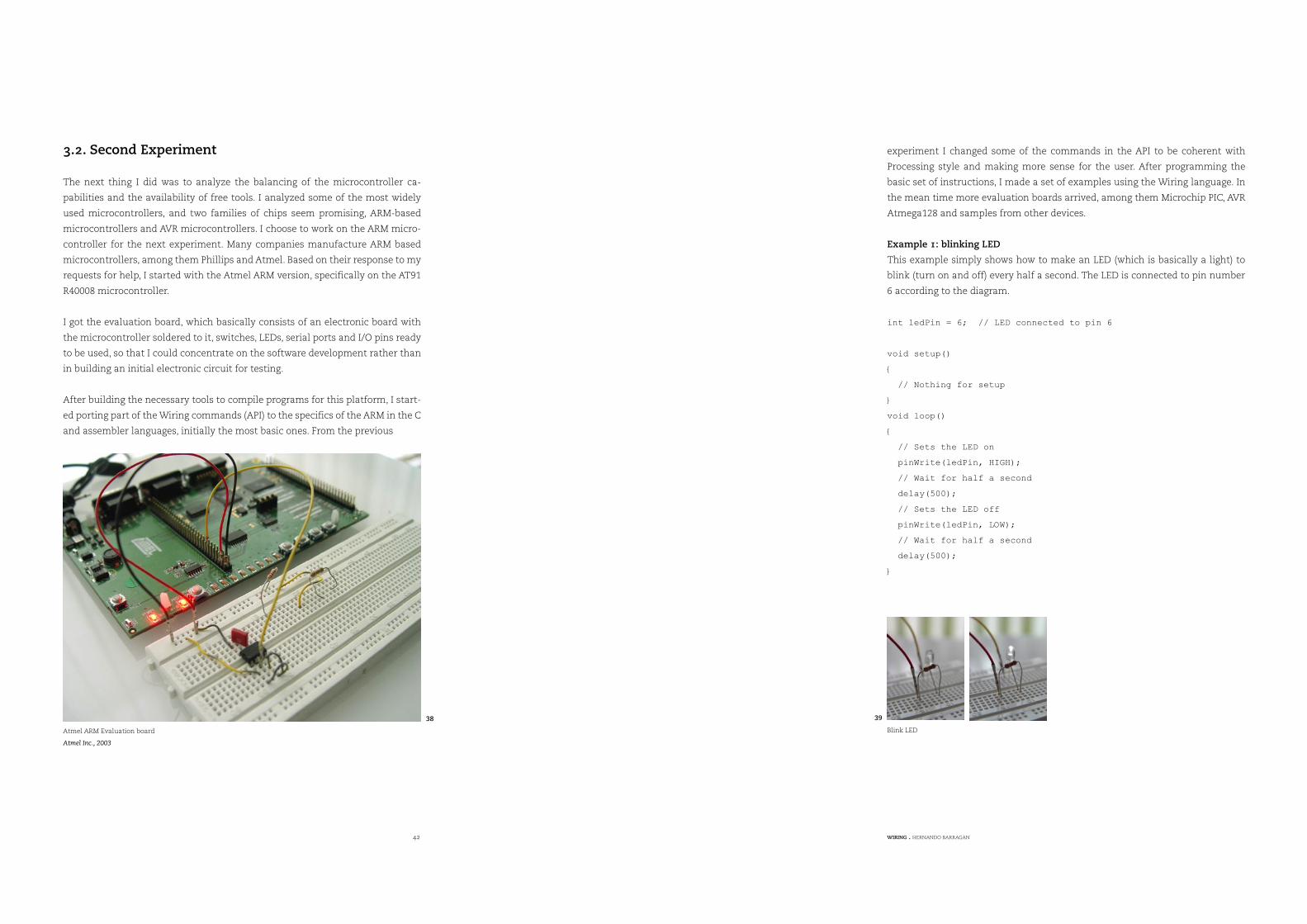
I got the evaluation board, which basically consists of an electronic board with
the microcontroller soldered to it, switches, LEDs, serial ports and I/O pins ready
to be used, so that I could concentrate on the software development rather than
in building an initial electronic circuit for testing.
After building the necessary tools to compile programs for this platform, I start-
ed porting part of the Wiring commands (API) to the specifics of the ARM in the C
and assembler languages, initially the most basic ones. From the previous
This example simply shows how to make an LED (which is basically a light) to
blink (turn on and off) every half a second. The LED is connected to pin number
6 according to the diagram.
int ledPin = 6; // LED connected to pin 6
void setup()
{
// Nothing for setup
}
void loop()
{
// Sets the LED on
pinWrite(ledPin, HIGH);
// Wait for half a second
delay(500);
// Sets the LED off
pinWrite(ledPin, LOW);
// Wait for half a second
delay(500);
}
Atmel ARM Evaluation board
Atmel Inc., 2003
38
Blink LED
39
experiment I changed some of the commands in the API to be coherent with
Processing style and making more sense for the user. After programming the
basic set of instructions, I made a set of examples using the Wiring language. In
the mean time more evaluation boards arrived, among them Microchip PIC, AVR
Atmega128 and samples from other devices.
Example 1: blinking LED
44 WIRING . HERNANDO BARRAGAN
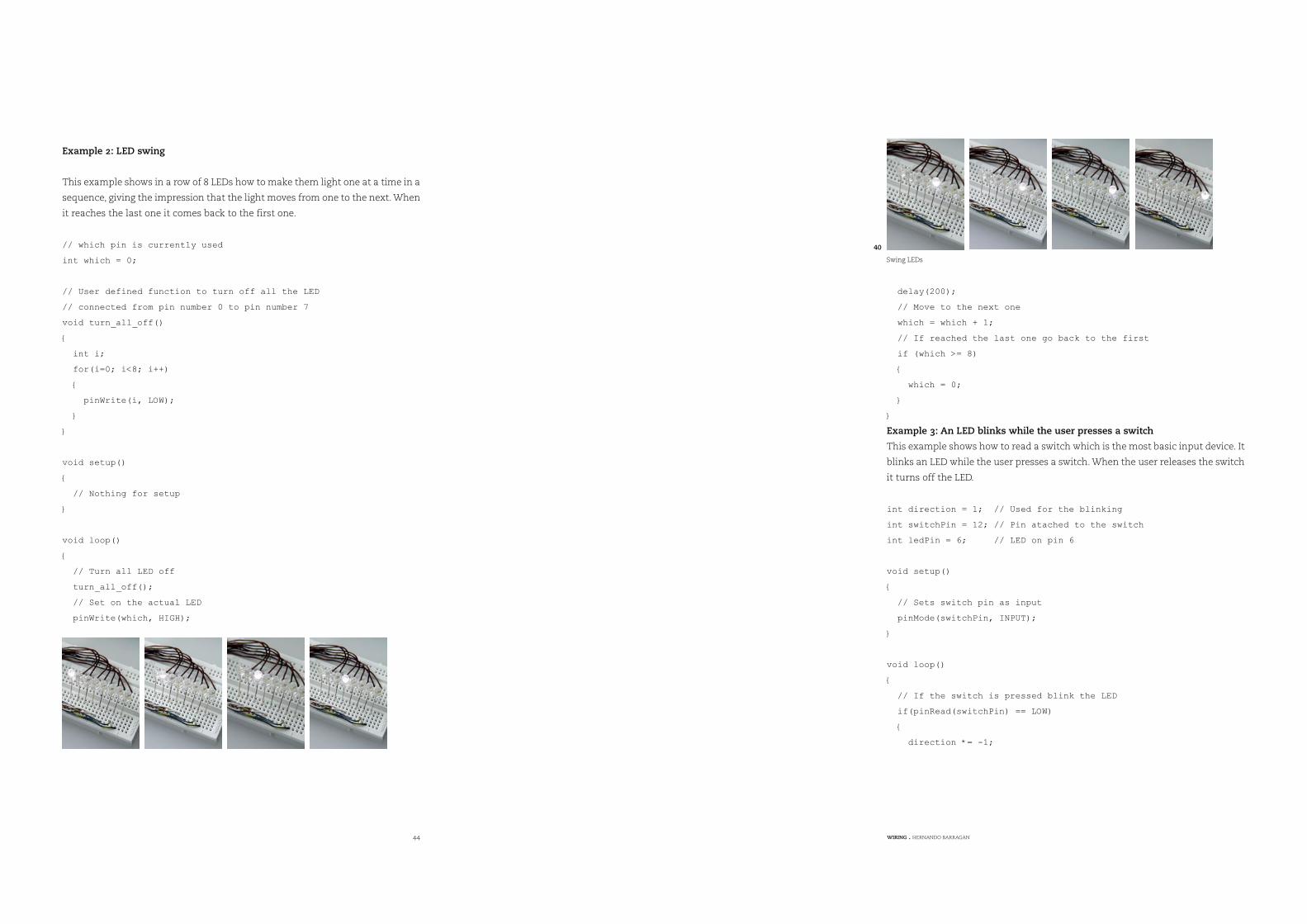
Example 2: LED swing
This example shows in a row of 8 LEDs how to make them light one at a time in a
sequence, giving the impression that the light moves from one to the next. When
it reaches the last one it comes back to the first one.
// which pin is currently used
int which = 0;
// User defined function to turn off all the LED
// connected from pin number 0 to pin number 7
void turn_all_off()
{
int i;
for(i=0; i<8; i++)
{
pinWrite(i, LOW);
}
}
void setup()
{
// Nothing for setup
}
void loop()
{
// Turn all LED off
turn_all_off();
// Set on the actual LED
pinWrite(which, HIGH);
delay(200);
// Move to the next one
which = which + 1;
// If reached the last one go back to the first
if (which >= 8)
{
which = 0;
}
}
Example 3: An LED blinks while the user presses a switch
This example shows how to read a switch which is the most basic input device. It
blinks an LED while the user presses a switch. When the user releases the switch
it turns off the LED.
int direction = 1; // Used for the blinking
int switchPin = 12; // Pin atached to the switch
int ledPin = 6; // LED on pin 6
void setup()
{
// Sets switch pin as input
pinMode(switchPin, INPUT);
}
void loop()
{
// If the switch is pressed blink the LED
if(pinRead(switchPin) == LOW)
{
direction *= -1;
Swing LEDs
40

46 WIRING . HERNANDO BARRAGAN
// Alternate between on and off the LED
if (direction == 1)
pinWrite(ledPin, HIGH);
else
pinWrite(ledPin, LOW);
delay(200);
}
// If not pressed, turn off the LED
else
{
pinWrite(ledPin, LOW);
}
}
Example 4: Controlling a screen-based application running on a PC through
touching an object.
This example shows how an object becomes a very simple interactive device to
control a screen-based application running in a remote PC. Basically the PC is
running a graphic application, which receives input from the serial port. The PCs
serial port is connected to the microcontroller’s serial port. The microcontroller
is waiting for user input and when the user presses the object, it sends a signal
through the serial port causing the PCs running application to react by changing
the shape and movement of basic graphic forms on the screen.
In order for the microcontroller to detect the event of touching, it has connected
a touch sensor to one of the pins. The touch sensor acts a simple switch, which
is turned on when the user touches an electrode and off when the user releases
it, so the electrode is inside the interactive object.
// Touch sensor will be attached to pin 23
int touchSensor = 23;
void setup()
{
// Starts the serial port with default settings
beginSerial(9600);
// Sets touch sensor pin as input
pinMode(touchSensor, INPUT);
}
void loop()
{
// If the user touches the object sends a ’1’
// and waits until he stops touching
if(pinRead(touchSensor) == HIGH)
{
serialWrite(’1’);
while(pinRead(touchSensor) == HIGH)
{
Controlling a screen-based application
42
The LED blinks when the
switch is pressed
41
48 WIRING . HERNANDO BARRAGAN
3.3. Third Experiment
The third experiment consists again of porting and testing the existing Wiring
API to the AVR microcontroller, specifically to the atmega128. This microcon-
troller has a very good balance in terms of power, features and price. I received
an evaluation board from BDMICRO. This board provides access to all the fea-
tures of the microcontroller without adding any extra complex devices.
After some time the API was at the same level as the ARM version. After testing
the existing examples, they were made available from the wiring Web site along
with the updated API.
By porting the Wiring API to different microcontrollers, patterns started to
emerge that will help to support the future development of Wiring for other
microcontrollers.
I proceeded to implement the analog to digital conversion, digital to analog (PWM
Pulse width modulation), pulse generation, as well as some basic libraries, like
serial port communication, servo motor, the Liquid Crystal Display (LCD) library,
for generic text displays based on the HD44780 controller.
I received an evaluation board for the FTDI USB chip in order to provide support
for USB serial connection, since the serial port is a disappearing commodity in
the computer market today, especially on laptops. Wiring should support the se-
rial port communication without having to use an external adaptor for it.
FTDI provide drivers for the Microsoft Windows, Mac OSX and Linux operating
systems, which are necessary for the Wiring environment to run on this operat-
ing systems. The chip worked successfully after running some tests.
delay(500);
}
// When the user release the object send a ’0’
// through the serial port to the PC to indicate the object
// was released
serialWrite(’0’);
}
}
ARM microcontrollers are very powerful devices. In some setups they require
additional peripheral electronics. For the next experiment, I scaled down the
microcontroller to the Atmel AVR microcontrollers family, all of which are still
powerful but less expensive.
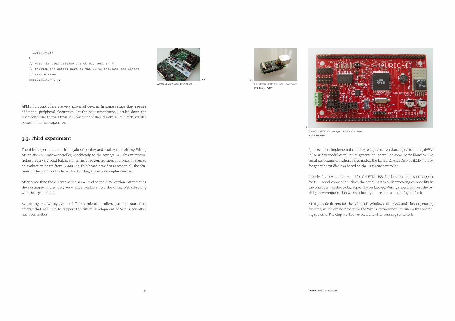
BDMICRO MAVRIC-II atmega128 Evaluation Board
BDMICRO, 2003
45
DLP Design USB232M Evaluation board
DLP Design, 2003
44
Atmel STK500 Evaluation board
43
50 WIRING . HERNANDO BARRAGAN
4. Design and Implementation
4.1. Wiring Software
I designed an API, the basic set of commands that are available for users in their
Wiring programs developed for their projects and explorations. Many modifi-
cations have been made since the original language proposal; maintaining the
coherence with Processing and with the concepts that need to be illustrated. As
soon as adjustments are made I developed examples that use the new command
set. By doing such examples, it helps me to detect which makes sense in the ac-
tual set of commands, and quickly make revisions and changes if necessary. This
API is available from the Wiring programming environment.
Structure
; (semicolon)= (assign)() (parentheses), (comma)// (comment)/* */ (multiline comment)void setup()loop() {} (curly braces)[] (array access). (dot)
Environment
delay()
Data
Primitiveintfloatcharbyteboolean
Control
Relational Operators> (greater than)< (less than)>= (greater than or equal to)<= (less than or equal to)== (equality)!= (inequality)
Iterationwhile() for()
Conditionalsif() else
Logical operators|| (logical OR)&& (logical AND)! (logical NOT)
Input /Output
Pin Digital I/OpinMode()digitalRead()digitalWrite()
Port Digital I/OportMode()portRead()portWrite()
Pin Analog InputanalogRead()
PWM (Analog) OutputanalogWrite()
Terminal KeyboardkeyPressed key keyPressed() keyReleased()
Time & Datemillis()second()
minute()hour()day()month()year()
TimingWTimermark() timerEvent()
Pulse GenerationbeginPulse()endPulse()pulseFrequency()pulseRun()pulseStop()pulseRunning()Pulse InputpulseIn()
Text OutputprintMode()print()
Math
Operators+ (add)- (subtract)* (multiply)/ (divide)++ (increment)-- (decrement)% (modulo)+= (add assign)-= (subtract assign)- (negation)
abs()sq() sqrt()
A set of small prototypical examples is being developed to illustrate the basics
of the media and the available commands of the language. These examples are
available in the Wiring Examples sketchbook distributed with the application
and from the Wiring web site Examples section.
From now on all the API changes and Examples will be directly posted and made
available from the Wiring web site in the Reference section.
Users can create their programs in the Wiring environment editor. The user’s
programs are compiled and then could be downloaded to the Wiring electronics
I/O board.
Once the program is downloaded to the Wiring I/O Board, it is executed on it.
4.2. Wiring Hardware
I designed the Wiring electronics I/O board. This I/O board is based on the Atmel
AVR atmega128 microcontroller, which is a powerful, scalable and cost effective.
The board has available 48 I/O digital pins, 8 Analog Input pins and 6 Analog
Output (PWM) pins. It also has two hardware serial ports, Two-wire Interface pro-
tocol (TWI), In System Programmer (ISP) connector for initial board setup, and
JTAG connector available for specialized debuggers. Some pins have different
functionality and special functions which is made available through the Wiring
pow() max() min() ceil() floor() constrain()
Trigonometrysin() cos() tan() atan2() radians() degrees()
Randomrandom()
Constants
PI ( 3.14159... )TWO_PI ( 6.28318... )HALF_PI ( 1.57079... )
Libraries
Libraries extend the basic func-tionality of Wiring. It is possible to write your own libraries.
Serial Supports communication between Wiring and external hardware via the serial port.
Servo Motor Basic servo motor manipulation library
LCD Display Basic LCD manipulation library
DC Motor Basic DC motor manipulation library.
Network (In progress)Sending and receiving data over a net of devices.
more to come...
Initial Wiring API
46
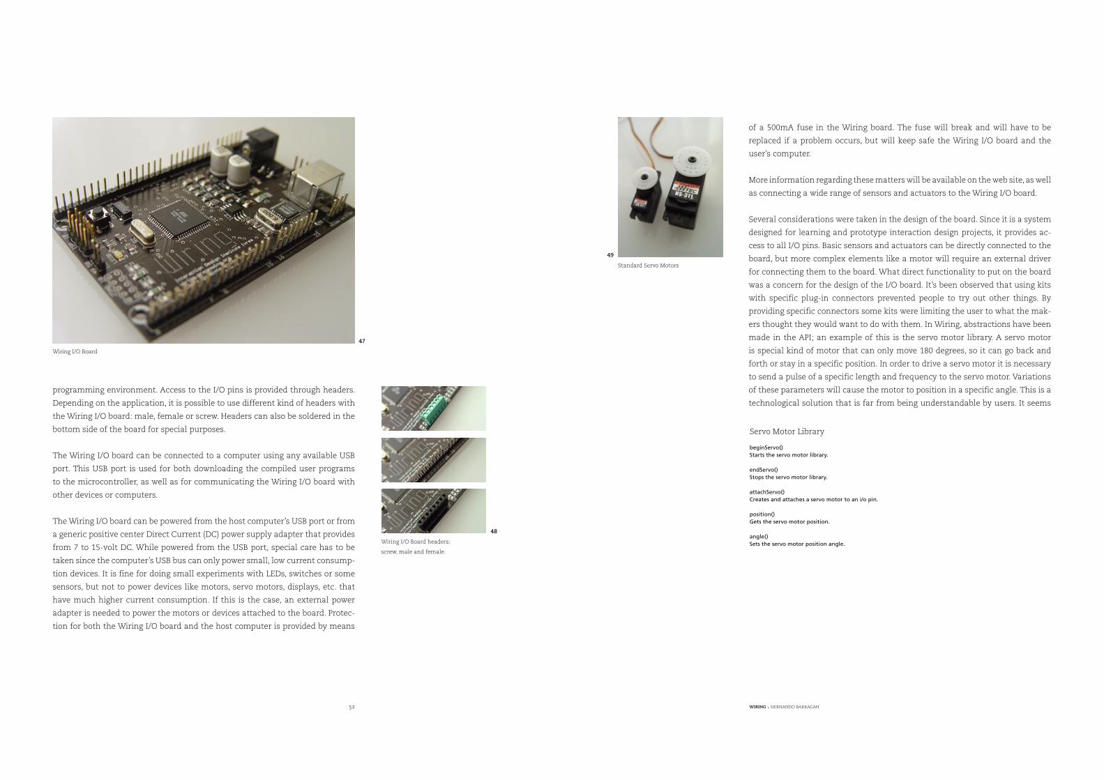
52 WIRING . HERNANDO BARRAGAN
programming environment. Access to the I/O pins is provided through headers.
Depending on the application, it is possible to use different kind of headers with
the Wiring I/O board: male, female or screw. Headers can also be soldered in the
bottom side of the board for special purposes.
The Wiring I/O board can be connected to a computer using any available USB
port. This USB port is used for both downloading the compiled user programs
to the microcontroller, as well as for communicating the Wiring I/O board with
other devices or computers.
The Wiring I/O board can be powered from the host computer’s USB port or from
a generic positive center Direct Current (DC) power supply adapter that provides
from 7 to 15-volt DC. While powered from the USB port, special care has to be
taken since the computer’s USB bus can only power small, low current consump-
tion devices. It is fine for doing small experiments with LEDs, switches or some
sensors, but not to power devices like motors, servo motors, displays, etc. that
have much higher current consumption. If this is the case, an external power
adapter is needed to power the motors or devices attached to the board. Protec-
tion for both the Wiring I/O board and the host computer is provided by means
of a 500mA fuse in the Wiring board. The fuse will break and will have to be
replaced if a problem occurs, but will keep safe the Wiring I/O board and the
user’s computer.
More information regarding these matters will be available on the web site, as well
as connecting a wide range of sensors and actuators to the Wiring I/O board.
Several considerations were taken in the design of the board. Since it is a system
designed for learning and prototype interaction design projects, it provides ac-
cess to all I/O pins. Basic sensors and actuators can be directly connected to the
board, but more complex elements like a motor will require an external driver
for connecting them to the board. What direct functionality to put on the board
was a concern for the design of the I/O board. It’s been observed that using kits
with specific plug-in connectors prevented people to try out other things. By
providing specific connectors some kits were limiting the user to what the mak-
ers thought they would want to do with them. In Wiring, abstractions have been
made in the API; an example of this is the servo motor library. A servo motor
is special kind of motor that can only move 180 degrees, so it can go back and
forth or stay in a specific position. In order to drive a servo motor it is necessary
to send a pulse of a specific length and frequency to the servo motor. Variations
of these parameters will cause the motor to position in a specific angle. This is a
technological solution that is far from being understandable by users. It seems
Servo Motor Library
beginServo()Starts the servo motor library.
endServo()Stops the servo motor library.
attachServo()Creates and attaches a servo motor to an i/o pin.
position()Gets the servo motor position.
angle()Sets the servo motor position angle.
Wiring I/O Board
47
Wiring I/O Board headers:
screw, male and female.
48
Standard Servo Motors
49
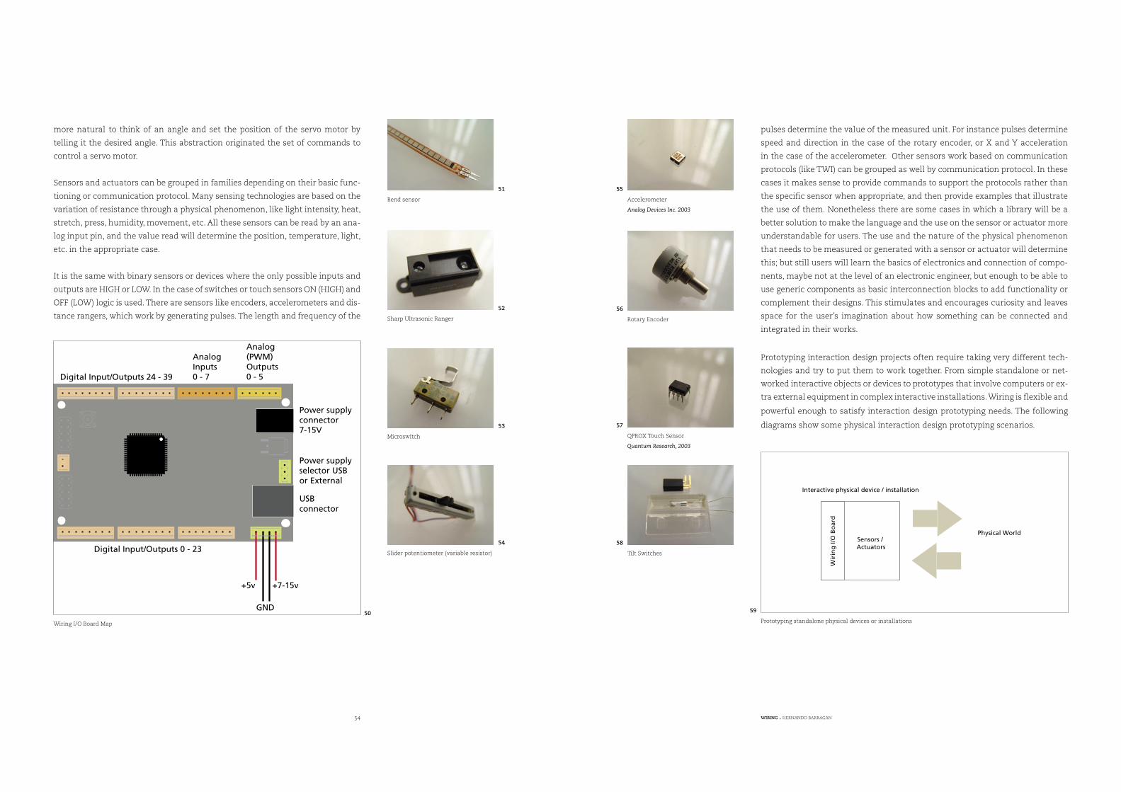
54 WIRING . HERNANDO BARRAGAN
more natural to think of an angle and set the position of the servo motor by
telling it the desired angle. This abstraction originated the set of commands to
control a servo motor.
Sensors and actuators can be grouped in families depending on their basic func-
tioning or communication protocol. Many sensing technologies are based on the
variation of resistance through a physical phenomenon, like light intensity, heat,
stretch, press, humidity, movement, etc. All these sensors can be read by an ana-
log input pin, and the value read will determine the position, temperature, light,
etc. in the appropriate case.
It is the same with binary sensors or devices where the only possible inputs and
outputs are HIGH or LOW. In the case of switches or touch sensors ON (HIGH) and
OFF (LOW) logic is used. There are sensors like encoders, accelerometers and dis-
tance rangers, which work by generating pulses. The length and frequency of the
Power supplyconnector7-15V
USBconnector
+5v +7-15v
GND
Digital Input/Outputs 0 - 23
Digital Input/Outputs 24 - 39
AnalogInputs0 - 7
Analog(PWM)Outputs0 - 5
Power supplyselector USBor External
pulses determine the value of the measured unit. For instance pulses determine
speed and direction in the case of the rotary encoder, or X and Y acceleration
in the case of the accelerometer. Other sensors work based on communication
protocols (like TWI) can be grouped as well by communication protocol. In these
cases it makes sense to provide commands to support the protocols rather than
the specific sensor when appropriate, and then provide examples that illustrate
the use of them. Nonetheless there are some cases in which a library will be a
better solution to make the language and the use on the sensor or actuator more
understandable for users. The use and the nature of the physical phenomenon
that needs to be measured or generated with a sensor or actuator will determine
this; but still users will learn the basics of electronics and connection of compo-
nents, maybe not at the level of an electronic engineer, but enough to be able to
use generic components as basic interconnection blocks to add functionality or
complement their designs. This stimulates and encourages curiosity and leaves
space for the user’s imagination about how something can be connected and
integrated in their works.
Interactive physical device / installation
Wir
ing
I/OB
oar
d
Sensors /Actuators
Physical World
Wiring I/O Board Map
50
Bend sensor
51
Sharp Ultrasonic Ranger
52
Microswitch
53
Slider potentiometer (variable resistor)
54
Accelerometer
Analog Devices Inc. 2003
55
Rotary Encoder
56
QPROX Touch Sensor
Quantum Research, 2003
57
Tilt Switches
58
Prototyping standalone physical devices or installations
59
Prototyping interaction design projects often require taking very different tech-
nologies and try to put them to work together. From simple standalone or net-
worked interactive objects or devices to prototypes that involve computers or ex-
tra external equipment in complex interactive installations. Wiring is flexible and
powerful enough to satisfy interaction design prototyping needs. The following
diagrams show some physical interaction design prototyping scenarios.
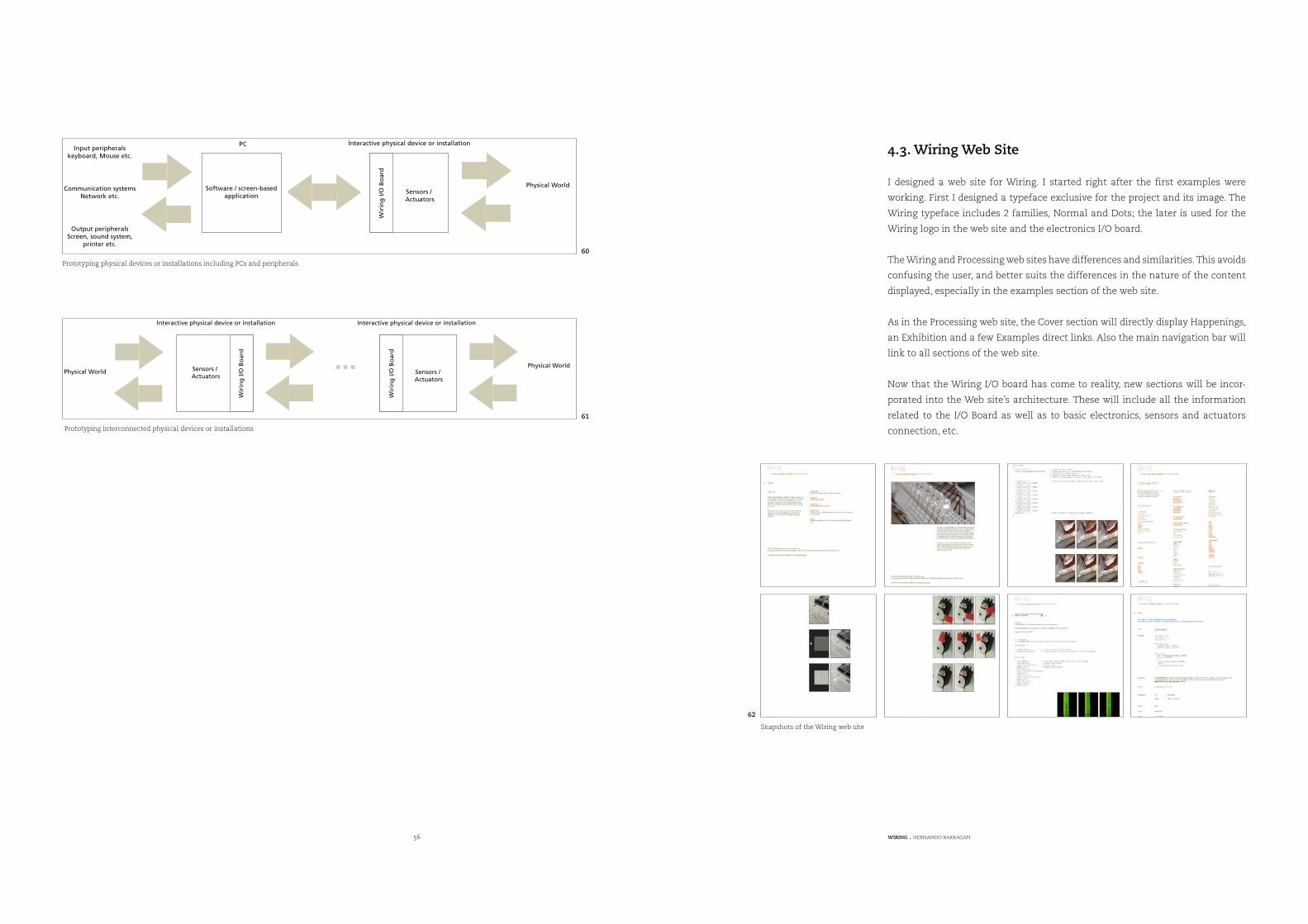
56 WIRING . HERNANDO BARRAGAN
PC Interactive physical device or installation
Software / screen-basedapplication
Wirin
gI/O
Boar
d
Sensors /Actuators
Input peripheralskeyboard, Mouse etc.
Output peripheralsScreen, sound system,
printer etc.
Communication systemsNetwork etc.
Physical World
Wir
ing
I/OB
oar
d
Sensors /Actuators
Physical World
Interactive physical device or installation
Wir
ing
I/OB
oar
d
Sensors /Actuators
Physical World
Interactive physical device or installation
4.3. Wiring Web Site
I designed a web site for Wiring. I started right after the first examples were
working. First I designed a typeface exclusive for the project and its image. The
Wiring typeface includes 2 families, Normal and Dots; the later is used for the
Wiring logo in the web site and the electronics I/O board.
The Wiring and Processing web sites have differences and similarities. This avoids
confusing the user, and better suits the differences in the nature of the content
displayed, especially in the examples section of the web site.
As in the Processing web site, the Cover section will directly display Happenings,
an Exhibition and a few Examples direct links. Also the main navigation bar will
link to all sections of the web site.
Now that the Wiring I/O board has come to reality, new sections will be incor-
porated into the Web site’s architecture. These will include all the information
related to the I/O Board as well as to basic electronics, sensors and actuators
connection, etc.
Prototyping physical devices or installations including PCs and peripherals
60
Prototyping interconnected physical devices or installations
61
Snapshots of the Wiring web site
62
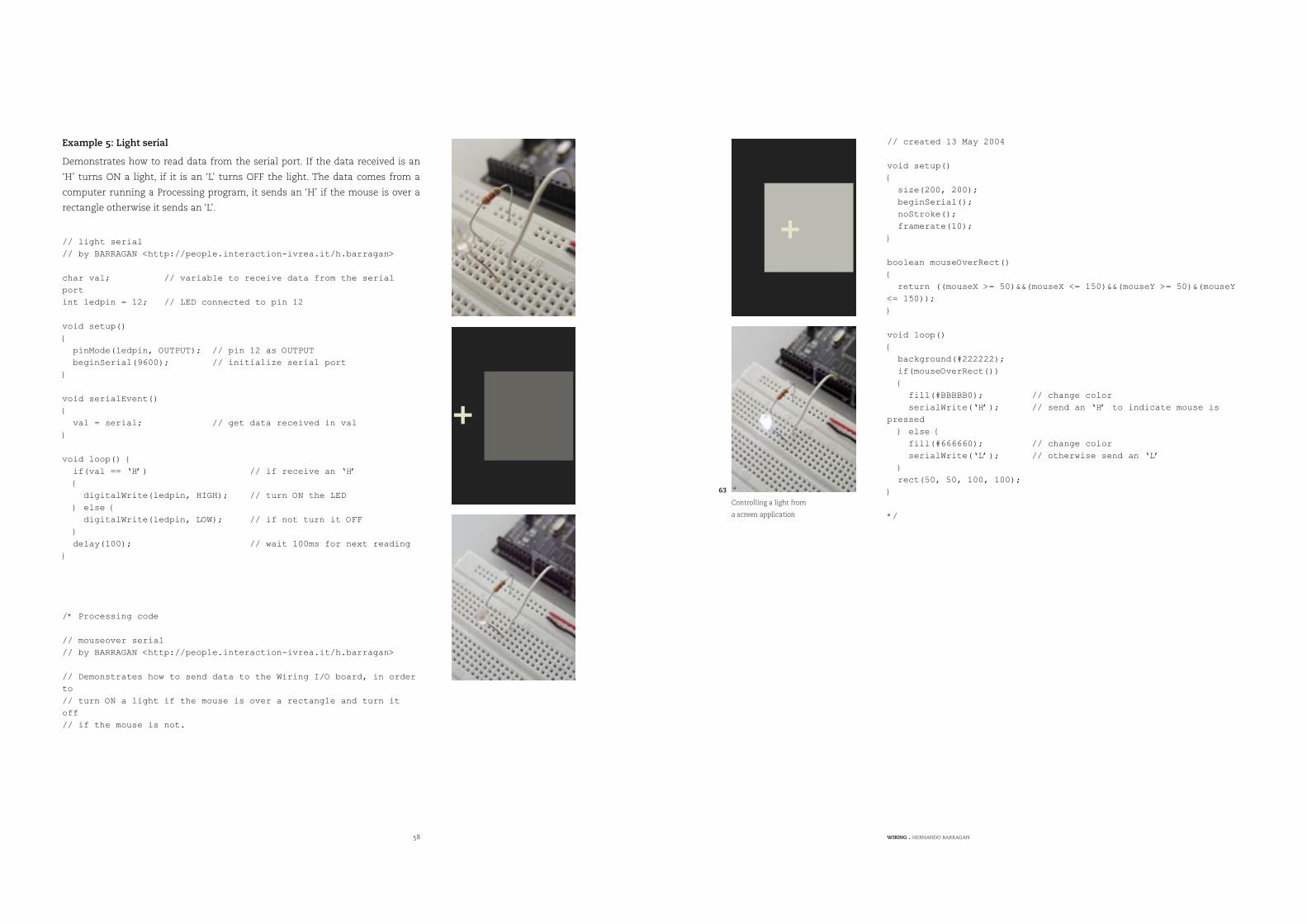
58 WIRING . HERNANDO BARRAGAN
Example 5: Light serial
Demonstrates how to read data from the serial port. If the data received is an
‘H’ turns ON a light, if it is an ‘L’ turns OFF the light. The data comes from a
computer running a Processing program, it sends an ‘H’ if the mouse is over a
rectangle otherwise it sends an ‘L’.
// light serial
// by BARRAGAN <http://people.interaction-ivrea.it/h.barragan>
char val; // variable to receive data from the serial
port
int ledpin = 12; // LED connected to pin 12
void setup()
{
pinMode(ledpin, OUTPUT); // pin 12 as OUTPUT
beginSerial(9600); // initialize serial port
}
void serialEvent()
{
val = serial; // get data received in val
}
void loop() {
if(val == ‘H’) // if receive an ‘H’
{
digitalWrite(ledpin, HIGH); // turn ON the LED
} else {
digitalWrite(ledpin, LOW); // if not turn it OFF
}
delay(100); // wait 100ms for next reading
}
/* Processing code
// mouseover serial
// by BARRAGAN <http://people.interaction-ivrea.it/h.barragan>
// Demonstrates how to send data to the Wiring I/O board, in order
to
// turn ON a light if the mouse is over a rectangle and turn it
off
// if the mouse is not.
// created 13 May 2004
void setup()
{
size(200, 200);
beginSerial();
noStroke();
framerate(10);
}
boolean mouseOverRect()
{
return ((mouseX >= 50)&&(mouseX <= 150)&&(mouseY >= 50)&(mouseY
<= 150));
}
void loop()
{
background(#222222);
if(mouseOverRect())
{
fill(#BBBBB0); // change color
serialWrite(‘H’); // send an ‘H’ to indicate mouse is
pressed
} else {
fill(#666660); // change color
serialWrite(‘L’); // otherwise send an ‘L’
}
rect(50, 50, 100, 100);
}
*/
Controlling a light from
a screen application
63
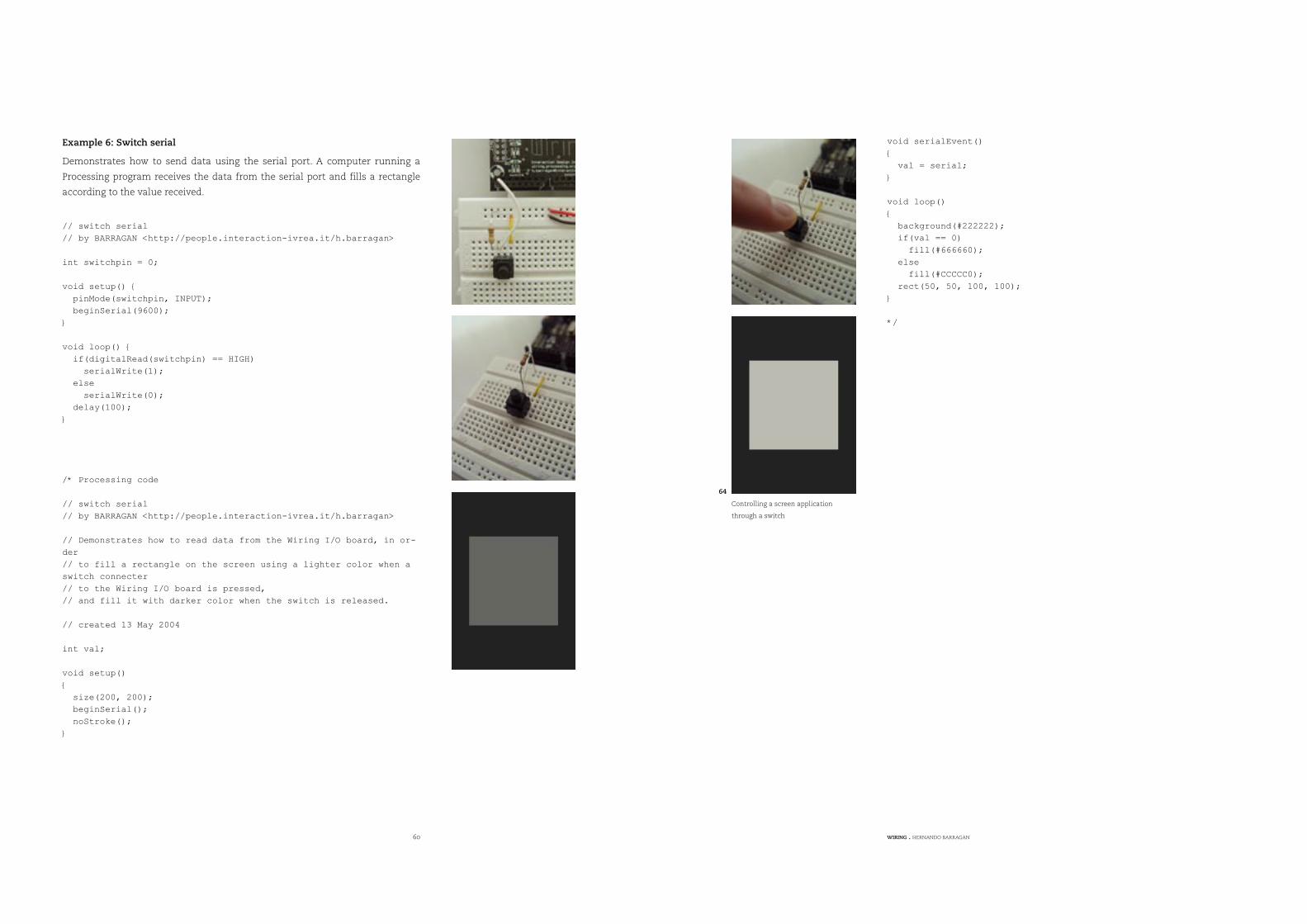
60 WIRING . HERNANDO BARRAGAN
Example 6: Switch serial
Demonstrates how to send data using the serial port. A computer running a
Processing program receives the data from the serial port and fills a rectangle
according to the value received.
// switch serial
// by BARRAGAN <http://people.interaction-ivrea.it/h.barragan>
int switchpin = 0;
void setup() {
pinMode(switchpin, INPUT);
beginSerial(9600);
}
void loop() {
if(digitalRead(switchpin) == HIGH)
serialWrite(1);
else
serialWrite(0);
delay(100);
}
/* Processing code
// switch serial
// by BARRAGAN <http://people.interaction-ivrea.it/h.barragan>
// Demonstrates how to read data from the Wiring I/O board, in or-
der
// to fill a rectangle on the screen using a lighter color when a
switch connecter
// to the Wiring I/O board is pressed,
// and fill it with darker color when the switch is released.
// created 13 May 2004
int val;
void setup()
{
size(200, 200);
beginSerial();
noStroke();
}
void serialEvent()
{
val = serial;
}
void loop()
{
background(#222222);
if(val == 0)
fill(#666660);
else
fill(#CCCCC0);
rect(50, 50, 100, 100);
}
*/
Controlling a screen application
through a switch
64
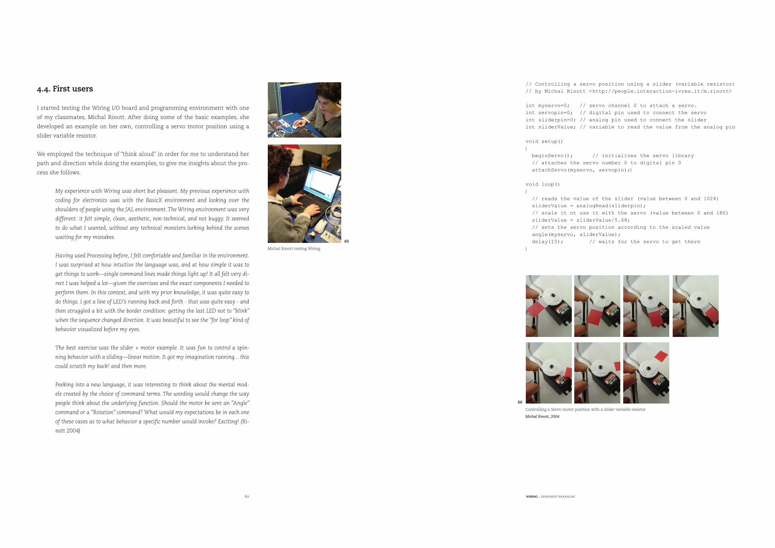
62 WIRING . HERNANDO BARRAGAN
4.4. First users
I started testing the Wiring I/O board and programming environment with one
of my classmates, Michal Rinott. After doing some of the basic examples, she
developed an example on her own, controlling a servo motor position using a
slider variable resistor.
We employed the technique of “think aloud” in order for me to understand her
path and direction while doing the examples, to give me insights about the pro-
cess she follows.
My experience with Wiring was short but pleasant. My previous experience with
coding for electronics was with the BasicX environment and looking over the
shoulders of people using the JAL environment. The Wiring environment was very
different: it felt simple, clean, aesthetic, non-technical, and not buggy. It seemed
to do what I wanted, without any technical monsters lurking behind the scenes
waiting for my mistakes.
Having used Processing before, I felt comfortable and familiar in the environment.
I was surprised at how intuitive the language was, and at how simple it was to
get things to work—single command lines made things light up! It all felt very di-
rect I was helped a lot—given the exercises and the exact components I needed to
perform them. In this context, and with my prior knowledge, it was quite easy to
do things. I got a line of LED’s running back and forth - that was quite easy - and
then struggled a bit with the border condition: getting the last LED not to “blink”
when the sequence changed direction. It was beautiful to see the “for loop” kind of
behavior visualized before my eyes.
The best exercise was the slider + motor example. It was fun to control a spin-
ning behavior with a sliding—linear motion. It got my imagination running... this
could scratch my back! and then more.
Peeking into a new language, it was interesting to think about the mental mod-
els created by the choice of command terms. The wording would change the way
people think about the underlying function. Should the motor be sent an “Angle”
command or a “Rotation” command? What would my expectations be in each one
of these cases as to what behavior a specific number would invoke? Exciting! (Ri-
nott 2004)
// Controlling a servo position using a slider (variable resistor)
// by Michal Rinott <http://people.interaction-ivrea.it/m.rinott>
int myservo=0; // servo channel 0 to attach a servo.
int servopin=0; // digital pin used to connect the servo
int sliderpin=0; // analog pin used to connect the slider
int sliderValue; // variable to read the value from the analog pin
void setup()
{
beginServo(); // initializes the servo library
// attaches the servo number 0 to digital pin 0
attachServo(myservo, servopin);}
void loop()
{
// reads the value of the slider (value between 0 and 1024)
sliderValue = analogRead(sliderpin);
// scale it ot use it with the servo (value between 0 and 180)
sliderValue = sliderValue/5.68;
// sets the servo position according to the scaled value
angle(myservo, sliderValue);
delay(15); // waits for the servo to get there
} Michal Rinott testing Wiring
65
Controlling a Servo motor position with a slider variable resistor
Michal Rinott, 2004
66
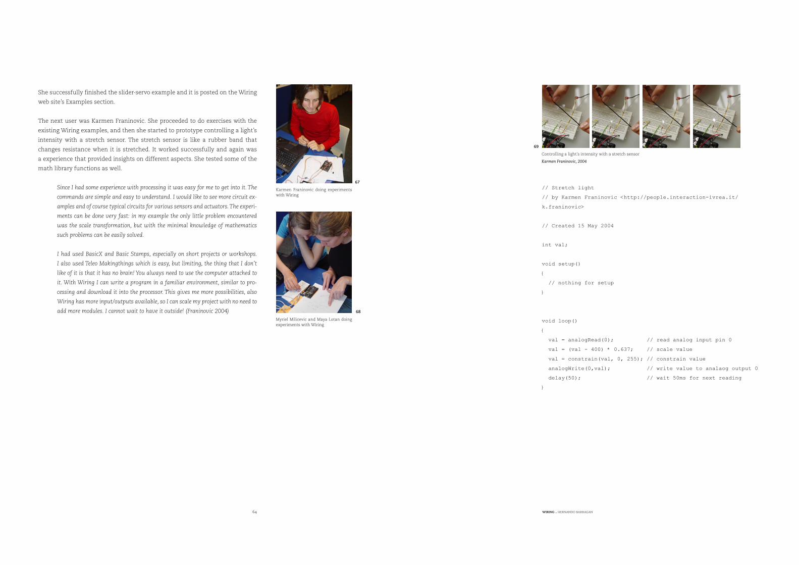
64 WIRING . HERNANDO BARRAGAN
// Stretch light
// by Karmen Franinovic <http://people.interaction-ivrea.it/
k.franinovic>
// Created 15 May 2004
int val;
void setup()
{
// nothing for setup
}
void loop()
{
val = analogRead(0); // read analog input pin 0
val = (val - 400) * 0.637; // scale value
val = constrain(val, 0, 255); // constrain value
analogWrite(0,val); // write value to analaog output 0
delay(50); // wait 50ms for next reading
}
She successfully finished the slider-servo example and it is posted on the Wiring
web site’s Examples section.
The next user was Karmen Franinovic. She proceeded to do exercises with the
existing Wiring examples, and then she started to prototype controlling a light’s
intensity with a stretch sensor. The stretch sensor is like a rubber band that
changes resistance when it is stretched. It worked successfully and again was
a experience that provided insights on different aspects. She tested some of the
math library functions as well.
Since I had some experience with processing it was easy for me to get into it. The
commands are simple and easy to understand. I would like to see more circuit ex-
amples and of course typical circuits for various sensors and actuators. The experi-
ments can be done very fast: in my example the only little problem encountered
was the scale transformation, but with the minimal knowledge of mathematics
such problems can be easily solved.
I had used BasicX and Basic Stamps, especially on short projects or workshops.
I also used Teleo Makingthings which is easy, but limiting, the thing that I don’t
like of it is that it has no brain! You always need to use the computer attached to
it. With Wiring I can write a program in a familiar environment, similar to pro-
cessing and download it into the processor. This gives me more possibilities, also
Wiring has more input/outputs available, so I can scale my project with no need to
add more modules. I cannot wait to have it outside! (Franinovic 2004)
Karmen Franinovic doing experiments with Wiring
67
Controlling a light’s intensity with a stretch sensor
Karmen Franinovic, 2004
69
Myriel Milicevic and Maya Lotan doing experiments with Wiring
68
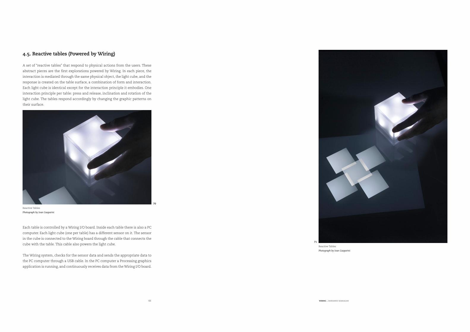
66 WIRING . HERNANDO BARRAGAN
4.5. Reactive tables (Powered by Wiring)
A set of “reactive tables” that respond to physical actions from the users. These
abstract pieces are the first explorations powered by Wiring. In each piece, the
interaction is mediated through the same physical object, the light cube, and the
response is created on the table surface, a combination of form and interaction.
Each light cube is identical except for the interaction principle it embodies. One
interaction principle per table: press and release, inclination and rotation of the
light cube. The tables respond accordingly by changing the graphic patterns on
their surface.
Each table is controlled by a Wiring I/O board. Inside each table there is also a PC
computer. Each light cube (one per table) has a different sensor on it. The sensor
in the cube is connected to the Wiring board through the cable that connects the
cube with the table. This cable also powers the light cube.
The Wiring system, checks for the sensor data and sends the appropriate data to
the PC computer through a USB cable. In the PC computer a Processing graphics
application is running, and continuously receives data from the Wiring I/O board.
Reactive Tables
Photograph by Ivan Gasparini
70
Reactive Tables
Photograph by Ivan Gasparini
71
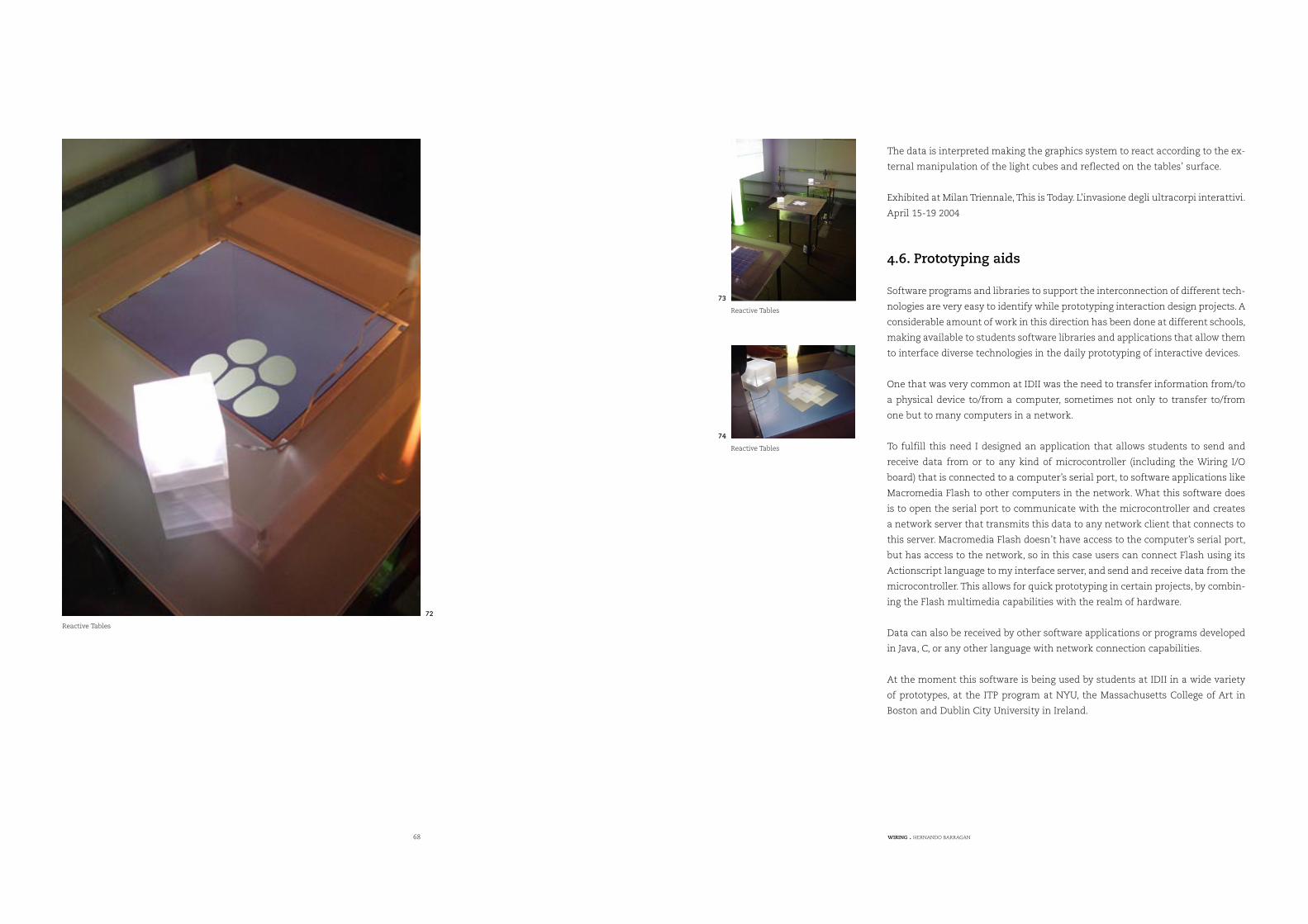
68 WIRING . HERNANDO BARRAGAN
The data is interpreted making the graphics system to react according to the ex-
ternal manipulation of the light cubes and reflected on the tables’ surface.
Exhibited at Milan Triennale, This is Today. L’invasione degli ultracorpi interattivi.
April 15-19 2004
4.6. Prototyping aids
Software programs and libraries to support the interconnection of different tech-
nologies are very easy to identify while prototyping interaction design projects. A
considerable amount of work in this direction has been done at different schools,
making available to students software libraries and applications that allow them
to interface diverse technologies in the daily prototyping of interactive devices.
One that was very common at IDII was the need to transfer information from/to
a physical device to/from a computer, sometimes not only to transfer to/from
one but to many computers in a network.
To fulfill this need I designed an application that allows students to send and
receive data from or to any kind of microcontroller (including the Wiring I/O
board) that is connected to a computer’s serial port, to software applications like
Macromedia Flash to other computers in the network. What this software does
is to open the serial port to communicate with the microcontroller and creates
a network server that transmits this data to any network client that connects to
this server. Macromedia Flash doesn’t have access to the computer’s serial port,
but has access to the network, so in this case users can connect Flash using its
Actionscript language to my interface server, and send and receive data from the
microcontroller. This allows for quick prototyping in certain projects, by combin-
ing the Flash multimedia capabilities with the realm of hardware.
Data can also be received by other software applications or programs developed
in Java, C, or any other language with network connection capabilities.
At the moment this software is being used by students at IDII in a wide variety
of prototypes, at the ITP program at NYU, the Massachusetts College of Art in
Boston and Dublin City University in Ireland.
Reactive Tables
72
Reactive Tables
73
Reactive Tables
74
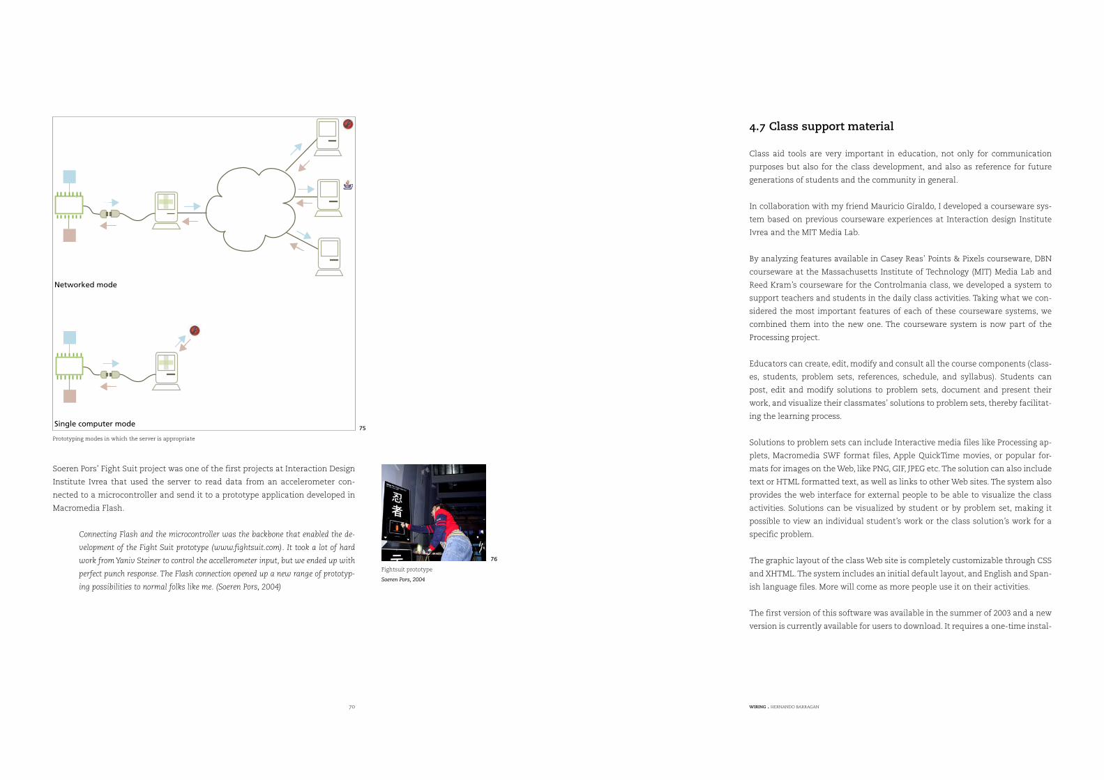
70 WIRING . HERNANDO BARRAGAN
Soeren Pors’ Fight Suit project was one of the first projects at Interaction Design
Institute Ivrea that used the server to read data from an accelerometer con-
nected to a microcontroller and send it to a prototype application developed in
Macromedia Flash.
Connecting Flash and the microcontroller was the backbone that enabled the de-
velopment of the Fight Suit prototype (www.fightsuit.com). It took a lot of hard
work from Yaniv Steiner to control the accellerometer input, but we ended up with
perfect punch response. The Flash connection opened up a new range of prototyp-
ing possibilities to normal folks like me. (Soeren Pors, 2004)
Networked mode
Single computer mode
4.7 Class support material
Class aid tools are very important in education, not only for communication
purposes but also for the class development, and also as reference for future
generations of students and the community in general.
In collaboration with my friend Mauricio Giraldo, I developed a courseware sys-
tem based on previous courseware experiences at Interaction design Institute
Ivrea and the MIT Media Lab.
By analyzing features available in Casey Reas’ Points & Pixels courseware, DBN
courseware at the Massachusetts Institute of Technology (MIT) Media Lab and
Reed Kram’s courseware for the Controlmania class, we developed a system to
support teachers and students in the daily class activities. Taking what we con-
sidered the most important features of each of these courseware systems, we
combined them into the new one. The courseware system is now part of the
Processing project.
Educators can create, edit, modify and consult all the course components (class-
es, students, problem sets, references, schedule, and syllabus). Students can
post, edit and modify solutions to problem sets, document and present their
work, and visualize their classmates’ solutions to problem sets, thereby facilitat-
ing the learning process.
Solutions to problem sets can include Interactive media files like Processing ap-
plets, Macromedia SWF format files, Apple QuickTime movies, or popular for-
mats for images on the Web, like PNG, GIF, JPEG etc. The solution can also include
text or HTML formatted text, as well as links to other Web sites. The system also
provides the web interface for external people to be able to visualize the class
activities. Solutions can be visualized by student or by problem set, making it
possible to view an individual student’s work or the class solution’s work for a
specific problem.
The graphic layout of the class Web site is completely customizable through CSS
and XHTML. The system includes an initial default layout, and English and Span-
ish language files. More will come as more people use it on their activities.
The first version of this software was available in the summer of 2003 and a new
version is currently available for users to download. It requires a one-time instal-
Prototyping modes in which the server is appropriate
75
Fightsuit prototype
Soeren Pors, 2004
76
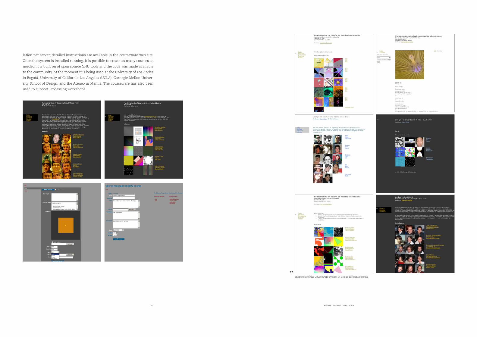
72 WIRING . HERNANDO BARRAGAN
lation per server; detailed instructions are available in the courseware web site.
Once the system is installed running, it is possible to create as many courses as
needed. It is built on of open source GNU tools and the code was made available
to the community. At the moment it is being used at the University of Los Andes
in Bogotá, University of California Los Angeles (UCLA), Carnegie Mellon Univer-
sity School of Design, and the Ateneo in Manila. The courseware has also been
used to support Processing workshops.
Snapshots of the Courseware system in use at different schools
77
74 WIRING . HERNANDO BARRAGAN
5. Conclusions and Future Direction
This project has been an incredible design challenge in on every level. From elec-
tronics to visual design, it forced me to execute tasks that required many skills.
In this sense it has been an amazing learning experience.
I found obstacles at every turn; some were challenging problems, others more
like dead ends that forced me to step back and try a different approach.
For my experience, it was very important to keep open to change and alterna-
tives; it is easy to get caught into something that makes us feel comfortable,
specially being in love with technology. In that sense I think my experience as an
artist and designer helped me in achieving some balance and getting alternative
perspectives of the problems involved in this project.
This project is just starting; a considerable amount of work has to be done to
take it further and to the extent I intended. From my thesis work, Wiring is in its
initial stage. Now the tools need to be tuned and perfected through the experi-
ence and use in school environments and by the community in general.
I am very excited and challenged with the work done, and the expected question:
what’s next? Everything! I think. It is also exciting to think of the kind of works
that hopefully people will do with Wiring.
Processing has opened a path for this project, not only in terms of community,
teaching methodologies or technology; however, only the use and experience of
Wiring will give me the necessary insights for improvements.
As was the experience with Processing, I expect that my running of workshops
will help me gain the necessary teaching experience as I more finely tune the
curriculums to achieve the goals of the project.
I devised this project to be used along with Processing to teach in academic en-
vironments; doing the initial learning-to-program steps with Processing, then
moving into learning basic electronics with Wiring and doing things in parallel.
Both will complement each other in taking the user’s design experiences into the
physical world.
The Wiring programming environment will be subject of constant improvements;
that’s the nature of software. At the moment an initial version with the basic
API is released; but major changes in the software will happen in the following
months to reflect the implementation of additional libraries and functionality, as
well as to include development environment improvements done for Processing,
since Processing and Wiring share the programming environment.
Another important feature that will be added for the next release is the support
for some of the lower-end microcontrollers of the Atmel AVR Atmega family, to
satisfy the user’s needs to deploy higher number of prototypes of its designs in a
more cost-effective manner.
Massive amounts of work have to be done in the communication and documen-
tation parts of the project. The Wiring web site will be a constant challenge re-
garding this matter.
The I/O Board hardware is designed to last for a longer period of time without
major changes. The Wiring board is powerful and flexible enough for the actual
and future needs of physical interaction design projects in the coming months.
76 WIRING . HERNANDO BARRAGAN
6. References
diSessa, Andrea A., Edward H. Lay, The Berkeley BOXER Project, February 25 2002,
<http://dewey.soe.berkeley.edu/boxer.html/index.html>
Kay, Alan, Squeakland, May 2004, <http://www.squeakland.org>
Logo Cmputer Systems Inc., Microworlds, May 2004, <http://www.microworlds.
com>
Maeda, John, Tom White, Ben Fry, Jessica Rosenkrantz, Design By Numbers, Aes-
thetics + Computation Group. Design By Numbers website. MIT Media Laboratory
Aesthetics + Computation Group. Cambridge, August 2 2003, <http://dbn.media.
mit.edu>
Reas, Casey, Ben Fry, Processing, MIT Media Laboratory and Interaction Design
Institute Ivrea, May 2004, <http://www.processing.org>
Martin, Fred, Fred’s World, University of Massachusetts LOWEL, Jan 27 2004,
<http://www.cs.uml.edu/~fredm/>
Massachusets Institute of Technology, 6.270 MIT’s Autonomous Robot Design
Competition, 2004, <http://www.mit.edu:8001/courses/6.270/home.html>
Martin, Fred. The Handy Board, handyboard.com, Aug 27 2003, <http://www.
handyboard.com>
MIT Media Laboratory Future of Learning Group, GoGo Board, MIT Media Labora-
tory, April 5 2004, <http://learning.media.mit.edu/projects/gogo>
Galbraith, Megan, Simon Greenwold, Justin Manor, nylon, MIT Media Laboratory,
Aesthetics + Computation Group, 2002, <http://acg.media.mit.edu/projects/ny-
lon>
Galbraith, Megan, megan galbraith master’s thesis, Embedded Systems for Com-
putational Garment Design, 2003, <http://acg.media.mit.edu/people/megan/the-
sis.html>
Stang, Pascal, AVRmini Boards, Santa Clara University, Nov 9 2003, <http://hub-
bard.engr.scu.edu/embedded/avr/avrmini>
Bishop, Durrell, Durrell Bishop, <http://www.durrellbishop.com>
Verplank, Bill, Bill Verplank, <http://www.billverplank.com>
Banzi, Massimo, potemkin.org, <http://www.potemkin.org>
Reas, Casey, GroupC.net / REAS, April 2004, <http://www.groupc.net>
UCLA Design | Media Arts, UCLA Design | Media Arts / SenseLab, April 2004, <
http://dma.ucla.edu/senselab>
O’Sullivan, Dan, Dan O’Sullivan, ITP NYU, May 2004, <http://fargo.itp.tsoa.nyu.
edu/~dano>
Igoe, Tom, Tom Igoe, ITP NYU, May 2004, <http://stage.itp.nyu.edu/~tigoe>
Berzowska, Joanna, Joanna Berzowska, Concordia University, May 2004, <http://
hybrid.concordia.ca/~joey>
Nimoy, Josh, The Work of Josh Nimoy, ITP NYU, March 2004, <http://www.jtnimoy.
com>
Stang, Pascal, SCU Robotics Systems Laboratories, Santa Clara University, April 1
2003, <http://hubbard.engr.scu.edu/embedded>
Lawson, Cynthia, Physical Computing, ITP NYU, 2003, http://stage.itp.tsoa.nyu.
edu/~cl457/pcomp
Co, Elise, elise co, Aesthetics + Computation Group. MIT Media Laboratory, Au-
gust 8 2001, <http://acg.media.mit.edu/people/elise>
Koser, Mikkel, Drawing Machine Project, Interaction Design, Royal College of Art,
May 2003, <http://proce55ing.beyondthree.com/tutorial/drawingmachine>
Van Ooijen, Wouter, Eur van Andel, Mark Gross, Javier Martinez, Craig Franklin,
Jal - Just Another Language, June 4 2003, <http://jal.sourceforge.net>

78 WIRING . HERNANDO BARRAGAN
Parallax Inc. Stamps in Class, Parallax Bbasic Stamp, <http://www.parallax.com/
html_pages/edu/index.asp>
Netmedia Inc. BasicX by NetMedia Inc., <http://www.basicx.com>
Microchip, Microchip Technology. Inc Home Page, May 2004, <http://www.micro-
chip.com>
Atmel Corporation, Atmel AVR 8-Bit RISC Homepage, May 2004, <http://www.
atmel.com/products/AVR>
Atmel Corporation, AT91 Arm-based Microcontrollers Homepage, May 2004,
http://www.atmel.com/products/AT91/
Systronix Inc, JStamp™, 2003, <http://www.systronix.com/jstamp>
Maxim/Dallas Semiconductor Corp., TINI: Introducing TINI, 2004, <http://www.
ibutton.com/TINI/index.html>
Rabbit Semiconductor, Rabbit Semiconductor | Microprocessors and Develop-
ment tools for Embedded Control and Communications, 2004, <http://www.rab-
bitsemiconductor.com>
Makingthings LLC, PRODUCTS, 2004, <http://www.makingthings.com/products/
products.htm>
Infusion Systems, Infusion Systems :: I-CubeX, MIDI sensor control for research,
education, art, music, dance and more, 2003, <http://www.infusionsystems.
com>
Pond Electronics, Pond – Embedded Systems Products, 2003, <http://www.pond.
ie/products/index.htm>
MIT Media Laboratory, aesthetics + computation group, MIT media laboratory,
2004, <http://acg.media.mit.edu>
Interactivity Consultants, Physical Interactivity and Interaction Design School
Guide, 2003, <http://www.interactivityconsultants.com/pages/alternate_index-
es/LowF_interactivity_curriculum_education.htm>
Zadeh, Lotfi , BISC Program; Soft Computing The Berkeley Initiative on Soft
Computing, Berkeley University of California, 2003, <http://www.cs.berkeley.
edu/~zadeh>
Mann, Steve, Wearable Computing, University of Toronto, 2003, <http://about.
eyetap.org/library/weekly/aa061500a.shtml>
Verplank, Bill, Physical Interaction Design – Autumn 2002, Interaction Design
Institute Ivrea, 2002, <http://www.interaction-ivrea.it/courses/2002-03/physical-
computing>
Banzi, Massimo, InflatedEgoTeachingPhysicalComputing, Interaction Design
Institute Ivrea, 2003, <http://conncomm.interaction-ivrea.it/zope/inflatedego/
TeachingPhysicalComputing>
Verplank, Bill, Max Mathews, MUSIC 250a / CS377C – HCI Theory and Practice,
Human Computer Interaction Design Stanford University, 2004, <http://ccrma-
www.stanford.edu/courses/250a>
ETH, Swiss Federal Institute of Technology, Wearable Computing Lab : Welcome
to the Wearable Computing Lab, ETH, Swiss Federal Institute of Technology Zur-
ich, Jan 4 2004, <http://www.wearable.ethz.ch>
Seymour, Sabine, fashionable technology, Parsons School of Design Center for
New Design, 2003, <http://a.parsons.edu/~fashiontech>
FSF Europe, FSF Europe – Education – Argumentation, Why give precedence to
Free Software at school?, Free Software Foundation Europe, February 2 2003,
<http://fsfeurope.org/projects/education/argumentation.en.html>
Utterback, Camille, Fang-Yu Lin, Major Studio - Physical Computing, Spring 2002,
Parsons School of Design, 2002, <http://a.parsons.edu/~linf/pc/sp02>
Camarata, Ken, Mark D Gross, Ellen Yi-Luen Do, [dmg . publications . Physical
Computing: A Design Studio that Bridges Art, Science, and Engineering], Wash-
ington University, March 13 2003, <http://dmg.caup.washington.edu/xmlSiteEn-
gine/browsers/stylin/publication134.html>
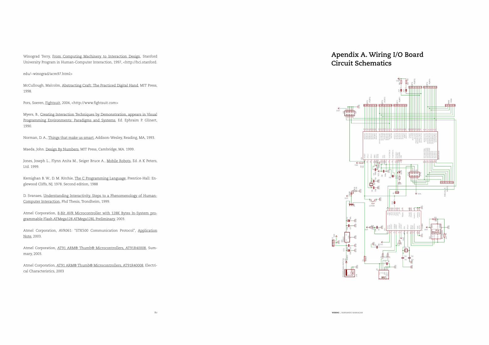
80 WIRING . HERNANDO BARRAGAN
Winograd Terry, From Computing Machinery to Interaction Design, Stanford
University Program in Human-Computer Interaction, 1997, <http://hci.stanford.
edu/~winograd/acm97.html>
McCullough, Malcolm, Abstracting Craft: The Practiced Digital Hand, MIT Press,
1998.
Pors, Soeren, Fightsuit, 2004, <http://www.fightsuit.com>
Myers, B., Creating Interaction Techniques by Demonstration, appears in Visual
Programming Environments: Paradigms and Systems, Ed. Ephraim P. Glinert,
1990.
Norman, D. A., Things that make us smart, Addison-Wesley, Reading, MA, 1993.
Maeda, John. Design By Numbers, MIT Press, Cambridge, MA. 1999.
Jones, Joseph L., Flynn Anita M., Seiger Bruce A., Mobile Robots, Ed. A K Peters,
Ltd. 1999.
Kernighan B. W., D. M. Ritchie, The C Programming Language, Prentice-Hall: En-
glewood Cliffs, NJ, 1978. Second edition, 1988
D. Svanaes, Understanding Interactivity. Steps to a Phenomenology of Human-
Computer Interaction, Phd Thesis, Trondheim, 1999.
Atmel Corporation, 8-Bit AVR Microcontroller with 128K Bytes In-System pro-
grammable Flash ATMega128 ATMega128L Preliminary, 2003.
Atmel Corporation, AVR061: “STK500 Communication Protocol”, Application
Note, 2003.
Atmel Corporation, AT91 ARM® Thumb® Microcontrollers, AT91R40008, Sum-
mary, 2003.
Atmel Corporation, AT91 ARM® Thumb® Microcontrollers, AT91R40008, Electri-
cal Characteristics, 2003
Apendix A. Wiring I/O Board Circuit Schematics
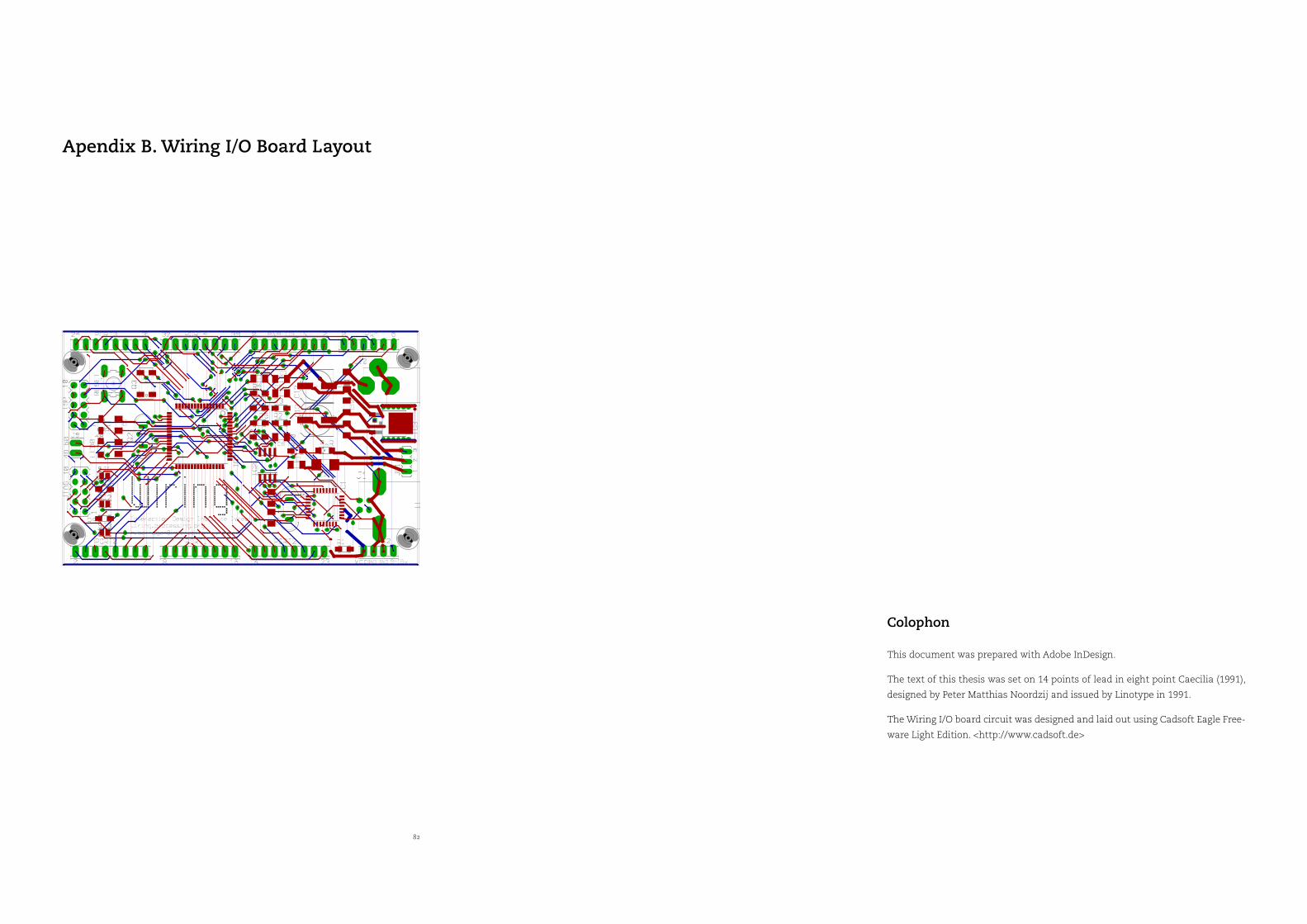
82 WIRING . HERNANDO BARRAGAN
Apendix B. Wiring I/O Board Layout
Colophon
This document was prepared with Adobe InDesign.
The text of this thesis was set on 14 points of lead in eight point Caecilia (1991),
designed by Peter Matthias Noordzij and issued by Linotype in 1991.
The Wiring I/O board circuit was designed and laid out using Cadsoft Eagle Free-
ware Light Edition. <http://www.cadsoft.de>

84