Wiring Diagrams - utcccs-cdn. · PDF fileLABEL DIAGRAM (On Unit) NO. 38AK 013-024 208/230-3-60...
16
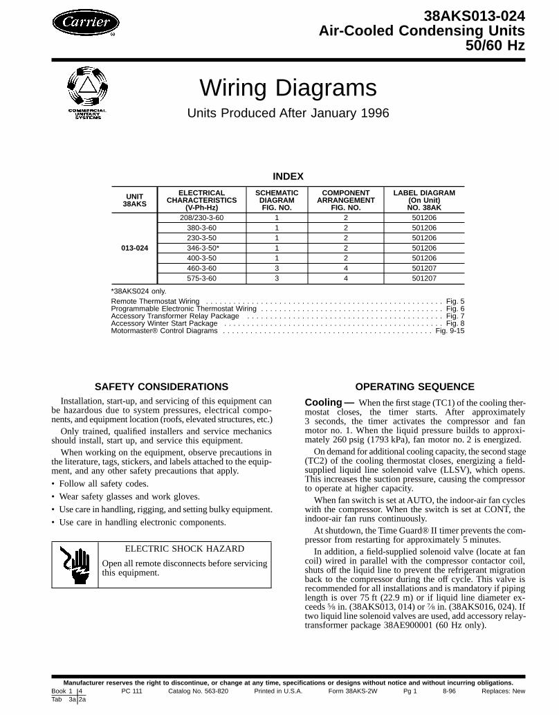
Wiring Diagrams Units Produced After January 1996 INDEX UNIT 38AKS ELECTRICAL CHARACTERISTICS (V-Ph-Hz) SCHEMATIC DIAGRAM FIG. NO. COMPONENT ARRANGEMENT FIG. NO. LABEL DIAGRAM (On Unit) NO. 38AK 013-024 208/230-3-60 1 2 501206 380-3-60 1 2 501206 230-3-50 1 2 501206 346-3-50* 1 2 501206 400-3-50 1 2 501206 460-3-60 3 4 501207 575-3-60 3 4 501207 *38AKS024 only. Remote Thermostat Wiring .................................................... Fig. 5 Programmable Electronic Thermostat Wiring ........................................ Fig. 6 Accessory Transformer Relay Package ........................................... Fig. 7 Accessory Winter Start Package ................................................ Fig. 8 Motormaster® Control Diagrams .............................................. Fig. 9-15 SAFETY CONSIDERATIONS Installation, start-up, and servicing of this equipment can be hazardous due to system pressures, electrical compo- nents, and equipment location (roofs, elevated structures, etc.) Only trained, qualified installers and service mechanics should install, start up, and service this equipment. When working on the equipment, observe precautions in the literature, tags, stickers, and labels attached to the equip- ment, and any other safety precautions that apply. • Follow all safety codes. • Wear safety glasses and work gloves. • Use care in handling, rigging, and setting bulky equipment. • Use care in handling electronic components. ELECTRIC SHOCK HAZARD Open all remote disconnects before servicing this equipment. OPERATING SEQUENCE Cooling — When the first stage (TC1) of the cooling ther- mostat closes, the timer starts. After approximately 3 seconds, the timer activates the compressor and fan motor no. 1. When the liquid pressure builds to approxi- mately 260 psig (1793 kPa), fan motor no. 2 is energized. On demand for additional cooling capacity, the second stage (TC2) of the cooling thermostat closes, energizing a field- supplied liquid line solenoid valve (LLSV), which opens. This increases the suction pressure, causing the compressor to operate at higher capacity. When fan switch is set at AUTO, the indoor-air fan cycles with the compressor. When the switch is set at CONT, the indoor-air fan runs continuously. At shutdown, the Time Guard® II timer prevents the com- pressor from restarting for approximately 5 minutes. In addition, a field-supplied solenoid valve (locate at fan coil) wired in parallel with the compressor contactor coil, shuts off the liquid line to prevent the refrigerant migration back to the compressor during the off cycle. This valve is recommended for all installations and is mandatory if piping length is over 75 ft (22.9 m) or if liquid line diameter ex- ceeds 5 /8 in. (38AKS013, 014) or 7 /8 in. (38AKS016, 024). If two liquid line solenoid valves are used, add accessory relay- transformer package 38AE900001 (60 Hz only). 38AKS013-024 Air-Cooled Condensing Units 50/60 Hz Manufacturer reserves the right to discontinue, or change at any time, specifications or designs without notice and without incurring obligations. Book 1 4 Tab 3a 2a PC 111 Catalog No. 563-820 Printed in U.S.A. Form 38AKS-2W Pg 1 8-96 Replaces: New
Transcript of Wiring Diagrams - utcccs-cdn. · PDF fileLABEL DIAGRAM (On Unit) NO. 38AK 013-024 208/230-3-60...
Wiring DiagramsUnits Produced After January 1996
INDEX
UNIT38AKS
ELECTRICALCHARACTERISTICS
(V-Ph-Hz)
SCHEMATICDIAGRAMFIG. NO.
COMPONENTARRANGEMENT
FIG. NO.
LABEL DIAGRAM(On Unit)NO. 38AK
013-024
208/230-3-60 1 2 501206380-3-60 1 2 501206230-3-50 1 2 501206346-3-50* 1 2 501206400-3-50 1 2 501206460-3-60 3 4 501207575-3-60 3 4 501207
*38AKS024 only.Remote Thermostat Wiring . . . . . . . . . . . . . . . . . . . . . . . . . . . . . . . . . . . . . . . . . . . . . . . . . . . . Fig. 5Programmable Electronic Thermostat Wiring . . . . . . . . . . . . . . . . . . . . . . . . . . . . . . . . . . . . . . . . Fig. 6Accessory Transformer Relay Package . . . . . . . . . . . . . . . . . . . . . . . . . . . . . . . . . . . . . . . . . . . Fig. 7Accessory Winter Start Package . . . . . . . . . . . . . . . . . . . . . . . . . . . . . . . . . . . . . . . . . . . . . . . . Fig. 8Motormaster® Control Diagrams . . . . . . . . . . . . . . . . . . . . . . . . . . . . . . . . . . . . . . . . . . . . . . Fig. 9-15
SAFETY CONSIDERATIONSInstallation, start-up, and servicing of this equipment can
be hazardous due to system pressures, electrical compo-nents, and equipment location (roofs, elevated structures, etc.)Only trained, qualified installers and service mechanics
should install, start up, and service this equipment.When working on the equipment, observe precautions in
the literature, tags, stickers, and labels attached to the equip-ment, and any other safety precautions that apply.
• Follow all safety codes.
• Wear safety glasses and work gloves.
• Use care in handling, rigging, and setting bulky equipment.
• Use care in handling electronic components.
ELECTRIC SHOCK HAZARD
Open all remote disconnects before servicingthis equipment.
OPERATING SEQUENCE
Cooling— When the first stage (TC1) of the cooling ther-mostat closes, the timer starts. After approximately3 seconds, the timer activates the compressor and fanmotor no. 1. When the liquid pressure builds to approxi-mately 260 psig (1793 kPa), fan motor no. 2 is energized.On demand for additional cooling capacity, the second stage
(TC2) of the cooling thermostat closes, energizing a field-supplied liquid line solenoid valve (LLSV), which opens.This increases the suction pressure, causing the compressorto operate at higher capacity.When fan switch is set at AUTO, the indoor-air fan cycles
with the compressor. When the switch is set at CONT, theindoor-air fan runs continuously.At shutdown, the Time Guard® II timer prevents the com-
pressor from restarting for approximately 5 minutes.In addition, a field-supplied solenoid valve (locate at fan
coil) wired in parallel with the compressor contactor coil,shuts off the liquid line to prevent the refrigerant migrationback to the compressor during the off cycle. This valve isrecommended for all installations and is mandatory if pipinglength is over 75 ft (22.9 m) or if liquid line diameter ex-ceeds5⁄8 in. (38AKS013, 014) or7⁄8 in. (38AKS016, 024). Iftwo liquid line solenoid valves are used, add accessory relay-transformer package 38AE900001 (60 Hz only).
38AKS013-024Air-Cooled Condensing Units
50/60 Hz
Manufacturer reserves the right to discontinue, or change at any time, specifications or designs without notice and without incurring obligations.Book 1 4Tab 3a 2a
PC 111 Catalog No. 563-820 Printed in U.S.A. Form 38AKS-2W Pg 1 8-96 Replaces: New

Heating — If heating is desired, a heating/cooling ther-mostat (See Fig. 5-7) must be supplied. This thermostat en-ergizes a field-supplied relay, which operates heating con-trols and energizes the indoor-fan relay.When the fan switchis set at AUTO, the indoor-air fan cycles with the heatingcontrol. The indoor-air fan runs continuously when the fanswitch is set at CONT.
Fan Cycling — Fan cycling is employed for head pres-sure control. The no. 2 fan responds to liquid line pressure,cycling on at approximately 260 psig (1793 kPa) and off atapproximately 126 psig (869 kPa).
Winter Start Control (If Required) — InstallAccessoryPackage 38AE900021. See page 9 for further details.
LEGEND (Fig. 1-5, 14, 15)
NOTES (Fig. 1-4)1. Fan motor(s) are thermally protected. Compressor motors
are protected against primary single-phasing conditions.2. If any of the original factory installed wire must be
replaced, it must be replaced with type 90 C wire or itsequivalent.
3. Terminal block 2 (TB2) is for field external controlconnections, Class 2 wiring:Supply voltage at TB2 is 24 vacMaximum power available at TB2 is 31.5 va
4. Field-supplied component ratings:IFC sealed coil rating (24 vac) 12 va maximum.For 24-1-50:LLS sealed coil rating (24 vac) 23 va maximum.
For 24-1-60:LLS sealed coil rating (24 vac) 18 va maximum.Minimum thermostat electrical rating is 120 va (5 amp at24 vac).Minimum fan switch electrical rating is 60 va (2.5 ampat 24 vac).If two liquid line solenoid valves are used, add accessoryrelay transformer package 38AE900001 (60 Hz only).
5. LLS, controlled by TC2, activates one-half of evaporatorfor capacity control feature.
6. Use copper, copper-clad aluminum, or aluminum con-ductors for field power supply.
7. Insulate unused lead when changing tap for 208 v use.8. For field wiring, use 60 C rated wire.
C — Contactor, CompressorCAP — CapacitorCB — Circuit BreakerCH — Crankcase HeaterCOM — CommonCOMP — CompressorCR — Control RelayDu — Dummy TerminalEquip Gnd — Equipment GroundFCPS — Fan Cycling Pressure StatFU — FuseHD — Heating DeviceHPS — High-Pressure SwitchIFC — Indoor-Fan ContactorIP — Internal ProtectorLLS — Liquid Line SolenoidLLSV — Liquid Line Solenoid ValveLPS — Low-Pressure SwitchNEC — National Electrical CodeOFC — Outdoor-Fan ContactorOFM — Outdoor-Fan MotorOFR — Outdoor-Fan RelayTB — Terminal BlockTC — Thermostat-Cooling
TDR — Time Delay RelayTGD — Time Guard® CircuitTRAN — TransformerQT — Quadruple Terminal
Terminal Block Connection
Terminal (Unmarked)
Terminal (Marked)
Field Splice
Splice (Marked)
Factory WiringFactory SpliceField Control Wiring
Field Power Wiring
To indicate common potential only,not to represent wire.
2
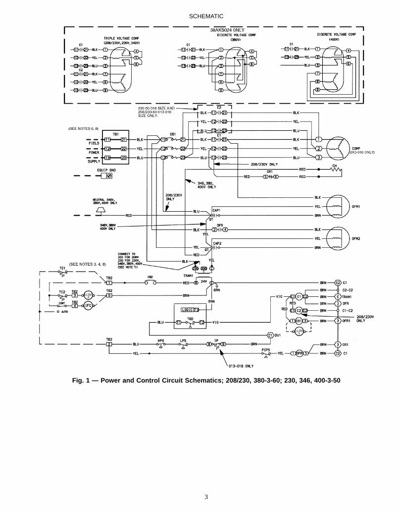
Fig. 1 — Power and Control Circuit Schematics; 208/230, 380-3-60; 230, 346, 400-3-50
SCHEMATIC
3

Fig. 2 — Component Arrangement; 208/230, 380-3-60; 230, 346, 400-3-50
COMPONENT ARRANGEMENT
4

Fig. 3 — Power and Control Circuit Schematics; 460, 575-3-60
SCHEMATIC
5

Fig. 4 — Component Arrangement; 460, 575-3-60
NOTES:1. Combination LLSV2 plus IFC vashould not exceed 30 va.
2. Do not exceed 5 va (24 vac)per coil R1.
} Use accessory relay-transformer package38AE900001 if theseva values must beexceeded.
Fig. 5 — Remote Thermostat Wiring;2-Step Cooling/2-Step Heating
COMPONENT ARRANGEMENT
6
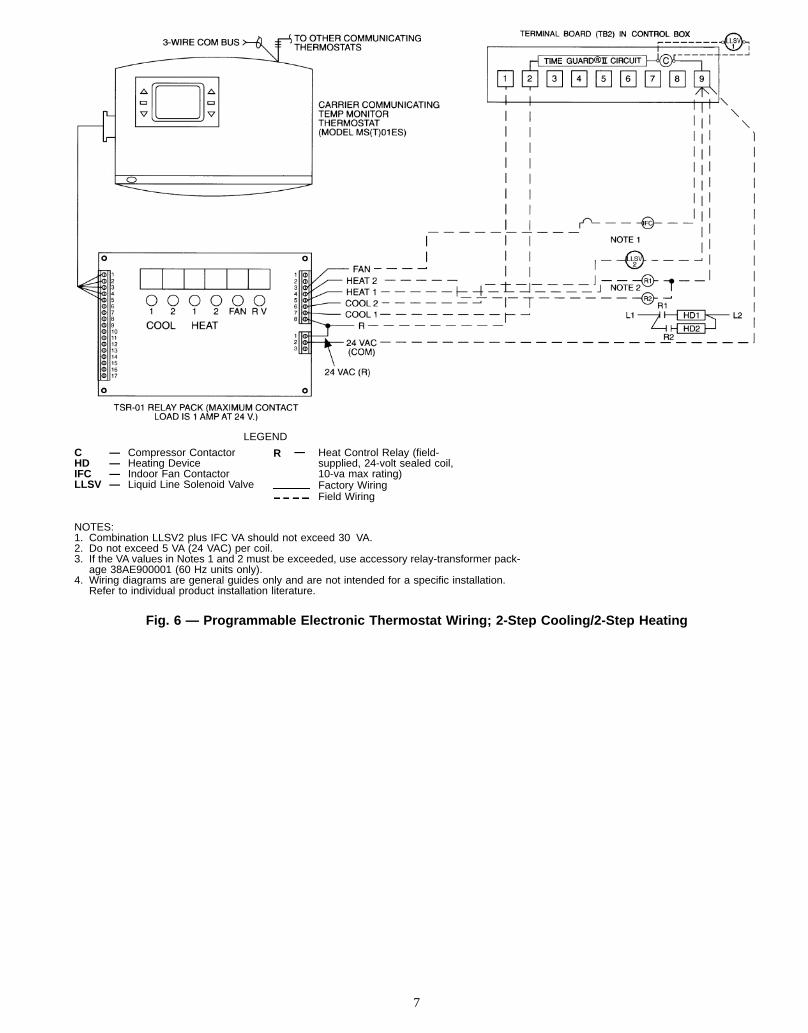
LEGEND
C — Compressor ContactorHD — Heating DeviceIFC — Indoor Fan ContactorLLSV — Liquid Line Solenoid Valve
R — Heat Control Relay (field-supplied, 24-volt sealed coil,10-va max rating)Factory WiringField Wiring
NOTES:1. Combination LLSV2 plus IFC VA should not exceed 30 VA.2. Do not exceed 5 VA (24 VAC) per coil.3. If the VA values in Notes 1 and 2 must be exceeded, use accessory relay-transformer pack-
age 38AE900001 (60 Hz units only).4. Wiring diagrams are general guides only and are not intended for a specific installation.
Refer to individual product installation literature.
Fig. 6 — Programmable Electronic Thermostat Wiring; 2-Step Cooling/2-Step Heating
7
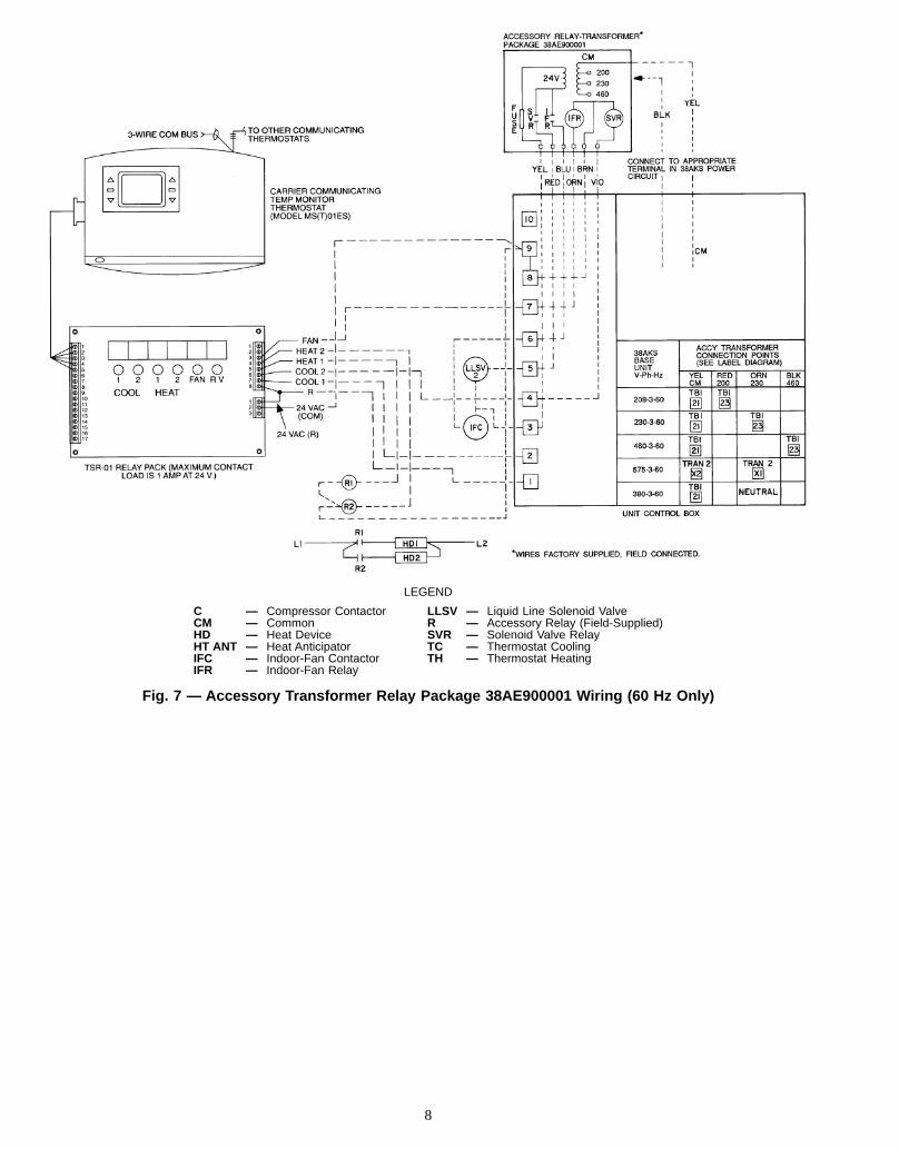
LEGEND
C — Compressor Contactor LLSV — Liquid Line Solenoid ValveCM — Common R — Accessory Relay (Field-Supplied)HD — Heat Device SVR — Solenoid Valve RelayHT ANT — Heat Anticipator TC — Thermostat CoolingIFC — Indoor-Fan Contactor TH — Thermostat HeatingIFR — Indoor-Fan Relay
Fig. 7 — Accessory Transformer Relay Package 38AE900001 Wiring (60 Hz Only)
8

MOTORMASTER® CONTROL(LOW AMBIENT KIT)
INSTALLATIONThe accessory low-ambient kit contains a fan speed (Motor-
master) control device activated by a temperature sensor (Fig. 8).The kit controls condenser fan motor speed in response tothe saturated condensing temperature. For outdoor tempera-tures down to −20 F (−29 C), it maintains the condensingtemperature at 100610 F (3866 C).The low-ambient (Motormaster) control consists of a solid-
state circuit on a printed circuit board encased in an alumi-num extrusion. The control must be fastened to a panel inthe unit, and the sensor assembly (Fig. 8) mounted to a re-turn bend on the unit’s condenser coil. Parts necessary formounting control and sensor are included in the kit.
Pre-InstallationDISCONNECTUNIT POWER—To prevent electric shock,open and tag all disconnects before modifying the condens-ing unit.
INSTALL WINTER START CONTROL — The unit mustbe modified for winter start control before installing and us-ing the low-ambient kit. Order Winter Start Control acces-sory no. 38AE900021 and install according to the instruc-tions supplied with the kit. See Fig. 9 for wiring.
FABRICATE AND INSTALL WIND BAFFLES — The38AKS units equippedwith the low-ambient kit require bafflesto prevent wind crosscurrents from causing abnormal opera-tion as the fan is modulated. Construct and install wind bafflesas shown in Fig. 10.
VERIFY POWER WIRING — Power wiring must complywith NEC (National Electrical Code) and all requirements.Confirm that supply voltage meets minimum voltage speci-fied on the unit’s rating plate and that it matches the voltagerating of the low-ambient kit.
LEGEND
C — ContactorHPS — High-Pressure SwitchIP — Internal ProtectorLPS — Low-Pressure SwitchTDR — Time-Delay Relay
Field-Supplied Wiring
Fig. 9 — Connection Points, Time-Delay Relay,Accessory Winter Start Package 38AE900021
KIT NO. VOLTS AMPS A B C32LT900301 All except 460 8.0 57⁄8 63⁄16 33⁄832LT900611 460 4.0 57⁄8 73⁄8 33⁄8
Fig. 8 — Low-Ambient (Motormaster) Control andSensor Assembly
LOW-AMBIENTCONTROL
SENSORASSEMBLY
AB
C
9
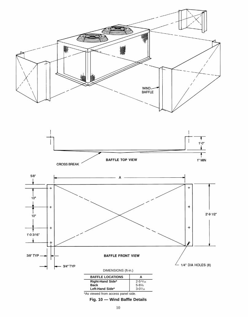
DIMENSIONS (ft-in.)
BAFFLE LOCATIONS ARight-Hand Side* 2-511⁄16Back 5-81⁄8Left-Hand Side* 3-07⁄16
*As viewed from access panel side.
Fig. 10 — Wind Baffle Details
10

Installation— After completing the pre-installation steps,proceeds as follows:
MOUNT CONTROL ASSEMBLY1. See Fig. 11 for the location of the access panel and Motor-
master® low-ambient control in the bottom of the unit.Remove the access panel.
2. Using the template supplied in this document, drill pilotholes for mounting the low-ambient control.
When drilling holes, be careful not to damage return coilbends inside unit.
3. Fasten control to unit with four no. 10 sheet metal screwsand star lockwashers provided. Lockwashers are re-quired to ensure electrical ground with condensing unit.
MOUNT SENSOR ASSEMBLY
The sensor assembly is fragile. Handle with care.
1. See Fig. 12 to determine where to locate sensor on coilreturn bend. As shown in Fig. 13, fasten sensor to returnbend with the supplied screw, plate washers, and nut. SeeTable 1 for sensor temperature vs resistance values.
2. Coil and secure excess wire inside the unit near the sen-sor or next to the low ambient control; provide additionalprotection against abrasion or movement of the wire ifnecessary.
3. Reinstall the access panel.
Table 1 — Sensor (Thermistor) Temperaturevs Resistance
TEMPERATURE NOMINAL RESISTANCE(Ohms)F C
60 16 775070 21 590077 25 500080 27 465090 32 3650100 38 2875110 43 2275120 49 1850
Fig. 11 — Location of Motormaster Low-Ambient Control
11
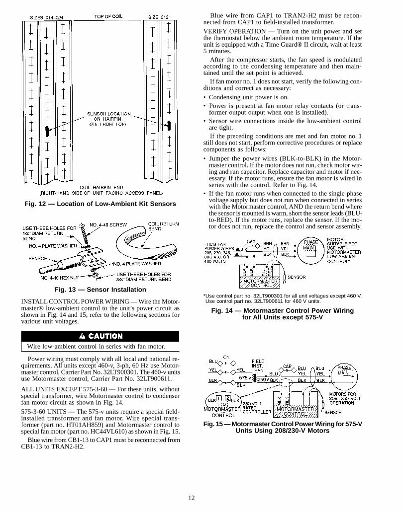
INSTALLCONTROLPOWERWIRING—Wire theMotor-master® low-ambient control to the unit’s power circuit asshown in Fig. 14 and 15; refer to the following sections forvarious unit voltages.
Wire low-ambient control in series with fan motor.
Power wiring must comply with all local and national re-quirements. All units except 460-v, 3-ph, 60 Hz use Motor-master control, Carrier Part No. 32LT900301. The 460-v unitsuse Motormaster control, Carrier Part No. 32LT900611.
ALL UNITS EXCEPT 575-3-60 — For these units, withoutspecial transformer, wire Motormaster control to condenserfan motor circuit as shown in Fig. 14.
575-3-60 UNITS — The 575-v units require a special field-installed transformer and fan motor. Wire special trans-former (part no. HT01AH859) and Motormaster control tospecial fan motor (part no. HC44VL610) as shown in Fig. 15.Blue wire fromCB1-13 to CAP1must be reconnected from
CB1-13 to TRAN2-H2.
Blue wire from CAP1 to TRAN2-H2 must be recon-nected from CAP1 to field-installed transformer.
VERIFY OPERATION — Turn on the unit power and setthe thermostat below the ambient room temperature. If theunit is equipped with a Time Guard® II circuit, wait at least5 minutes.After the compressor starts, the fan speed is modulated
according to the condensing temperature and then main-tained until the set point is achieved.If fan motor no. 1 does not start, verify the following con-
ditions and correct as necessary:
• Condensing unit power is on.• Power is present at fan motor relay contacts (or trans-former output output when one is installed).
• Sensor wire connections inside the low-ambient controlare tight.If the preceding conditions are met and fan motor no. 1
still does not start, perform corrective procedures or replacecomponents as follows:
• Jumper the power wires (BLK-to-BLK) in the Motor-master control. If the motor does not run, check motor wir-ing and run capacitor. Replace capacitor and motor if nec-essary. If the motor runs, ensure the fan motor is wired inseries with the control. Refer to Fig. 14.
• If the fan motor runs when connected to the single-phasevoltage supply but does not run when connected in serieswith the Motormaster control, AND the return bend wherethe sensor is mounted is warm, short the sensor leads (BLU-to-RED). If the motor runs, replace the sensor. If the mo-tor does not run, replace the control and sensor assembly.
Fig. 12 — Location of Low-Ambient Kit Sensors
Fig. 13 — Sensor Installation*Use control part no. 32LT900301 for all unit voltages except 460 V.Use control part no. 32LT900611 for 460 V units.
Fig. 14 — Motormaster Control Power Wiringfor All Units except 575-V
Fig. 15—MotormasterControl PowerWiring for 575-VUnits Using 208/230-V Motors
12
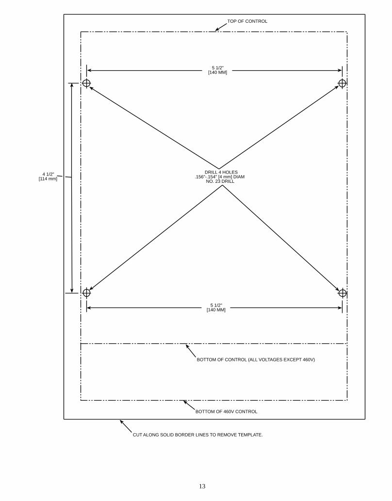
DRILL 4 HOLES.156"-.154" [4 mm] DIAM NO. 23 DRILL
BOTTOM OF CONTROL (ALL VOLTAGES EXCEPT 460V)
CUT ALONG SOLID BORDER LINES TO REMOVE TEMPLATE.
BOTTOM OF 460V CONTROL
5 1/2"[140 MM]
5 1/2"[140 MM]
4 1/2"[114 mm]
TOP OF CONTROL
13


Copyright 1996 Carrier Corporation
Manufacturer reserves the right to discontinue, or change at any time, specifications or designs without notice and without incurring obligations.Book 1 4Tab 3a 2a
PC 111 Catalog No. 563-820 Printed in U.S.A. Form 38AKS-2W Pg 16 8-96 Replaces: New