Ijnulauñ 1873 : Wi-Fi E-Journal „ %ffl5ðnnU Wi-Fi Wi Fi Wi ...

Wireless Wi-Fi
Dual Channel Wi-Fi™ Specification
WR-SP-DC-WiFi-I01-190702 ISSUED
Notice
This Wireless specification is the result of a cooperative effort undertaken at the direction of Cable Television Laboratories, Inc. for the benefit of the cable industry and its customers. You may download, copy, distribute, and reference the documents herein only for the purpose of developing products or services in accordance with such documents, and educational use. Except as granted by CableLabs® in a separate written license agreement, no license is granted to modify the documents herein (except via the Engineering Change process), or to use, copy, modify or distribute the documents for any other purpose.
This document may contain references to other documents not owned or controlled by CableLabs. Use and understanding of this document may require access to such other documents. Designing, manufacturing, distributing, using, selling, or servicing products, or providing services, based on this document may require intellectual property licenses from third parties for technology referenced in this document. To the extent this document contains or refers to documents of third parties, you agree to abide by the terms of any licenses associated with such third-party documents, including open source licenses, if any.
Cable Television Laboratories, Inc. 2019

WR-SP-DC-WiFi-I01-190702 Wireless
2 CableLabs 07/02/19
DISCLAIMER
This document is furnished on an "AS IS" basis and neither CableLabs nor its members provides any representation or warranty, express or implied, regarding the accuracy, completeness, noninfringement, or fitness for a particular purpose of this document, or any document referenced herein. Any use or reliance on the information or opinion in this document is at the risk of the user, and CableLabs and its members shall not be liable for any damage or injury incurred by any person arising out of the completeness, accuracy, or utility of any information or opinion contained in the document.
CableLabs reserves the right to revise this document for any reason including, but not limited to, changes in laws, regulations, or standards promulgated by various entities, technology advances, or changes in equipment design, manufacturing techniques, or operating procedures described, or referred to, herein.
This document is not to be construed to suggest that any company modify or change any of its products or procedures, nor does this document represent a commitment by CableLabs or any of its members to purchase any product whether or not it meets the characteristics described in the document. Unless granted in a separate written agreement from CableLabs, nothing contained herein shall be construed to confer any license or right to any intellectual property. This document is not to be construed as an endorsement of any product or company or as the adoption or promulgation of any guidelines, standards, or recommendations.

Dual Channel Wi-Fi™ Specification WR-SP-DC-WiFi-I01-190702
7/02/19 CableLabs 3
Document Status Sheet
Document Control Number: WR-SP-DC-WiFi-D02-190611
Document Title: Dual Channel Wi-Fi™ Specification
Revision History: W01 – May 2018
D01 – Released 04/12/2019
D02 – Released 06/11/2019
I01 – Released 07/02/2019
Date: July 02, 2019
Status: Work in Progress
Draft Issued Closed
Distribution Restrictions: Author Only CL/Member CL/ Member/ Vendor
Public
Key to Document Status Codes
Work in Progress An incomplete document, designed to guide discussion and generate feedback that may include several alternative requirements for consideration.
Draft A document in specification format considered largely complete, but lacking review by Members and vendors. Drafts are susceptible to substantial change during the review process.
Issued A generally public document that has undergone Member and Technology Supplier review, cross-vendor interoperability, and is for Certification testing if applicable. Issued Specifications are subject to the Engineering Change Process.
Closed A static document, reviewed, tested, validated, and closed to further engineering change requests to the specification through CableLabs.
Trademarks CableLabs® is a registered trademark of Cable Television Laboratories, Inc. Other CableLabs marks are listed at http://www.cablelabs.com/specs/certification/trademarks. All other marks are the property of their respective owners.

WR-SP-DC-WiFi-I01-190702 Wireless
4 CableLabs 07/02/19
Contents 1 SCOPE .................................................................................................................................................................. 6
1.1 Introduction and Purpose ............................................................................................................................... 6 1.2 Requirements ................................................................................................................................................. 6
2 REFERENCES .................................................................................................................................................... 7 2.1 Normative References.................................................................................................................................... 7 2.2 Informative References .................................................................................................................................. 7 2.3 Reference Acquisition.................................................................................................................................... 7
3 TERMS AND DEFINITIONS ............................................................................................................................ 8
4 ABBREVIATIONS .............................................................................................................................................. 9
5 OVERVIEW....................................................................................................................................................... 10 5.1 Access Point (AP) Requirements ................................................................................................................. 10
5.1.1 Communication .................................................................................................................................... 10 5.1.2 Data Channels ..................................................................................................................................... 10 5.1.3 Dual Channel Client Table .................................................................................................................. 10 5.1.4 Traffic Inspection, Filtering, and Routing ........................................................................................... 11
5.2 Dual Channel Client (DCC) Requirements .................................................................................................. 11 5.2.1 Communication .................................................................................................................................... 11 5.2.2 DCC Traffic Routing ............................................................................................................................ 11 5.2.3 DCC Auto-connecting to DC SSIDs .................................................................................................... 11
5.3 Dual Channel Client (DCC) Table ............................................................................................................... 11 5.4 Traffic Filter Profile ..................................................................................................................................... 12
5.4.1 Example Traffic Filter Profile ............................................................................................................. 12 5.5 Process Flows .............................................................................................................................................. 13
5.5.1 AP Initialization ................................................................................................................................... 13 5.5.2 DCC Initialization ............................................................................................................................... 13 5.5.3 DCC Disconnect .................................................................................................................................. 14 5.5.4 New Downstream Channel .................................................................................................................. 14 5.5.5 DC Move .............................................................................................................................................. 14 5.5.6 AP PC Disable or Quit ........................................................................................................................ 15 5.5.7 AP DC Disable .................................................................................................................................... 15
5.6 Message Definitions .................................................................................................................................... 15 5.6.1 Protocol Stack ...................................................................................................................................... 15 5.6.2 General Dual Channel Wi-Fi Message Syntax .................................................................................... 16 5.6.3 AP Messages ........................................................................................................................................ 17 5.6.4 DCC Messages ..................................................................................................................................... 18
5.7 Message Flows............................................................................................................................................. 19 5.7.1 DCC Initialization ............................................................................................................................... 19 5.7.2 DCC Disconnect .................................................................................................................................. 20 5.7.3 New Downstream Channel .................................................................................................................. 20 5.7.4 DC Move .............................................................................................................................................. 20 5.7.5 AP PC Disable or Quit ........................................................................................................................ 21 5.7.6 AP DC Disable .................................................................................................................................... 21
APPENDIX I ACKNOWLEDGEMENTS (INFORMATIVE) .......................................................................... 22
Dual Channel Wi-Fi™ Specification WR-SP-DC-WiFi-I01-190702
7/02/19 CableLabs 5
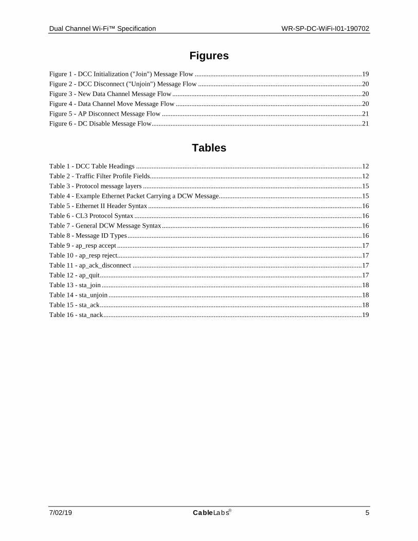
Figures Figure 1 - DCC Initialization ("Join") Message Flow ................................................................................................. 19 Figure 2 - DCC Disconnect ("Unjoin") Message Flow ............................................................................................... 20 Figure 3 - New Data Channel Message Flow .............................................................................................................. 20 Figure 4 - Data Channel Move Message Flow ............................................................................................................ 20 Figure 5 - AP Disconnect Message Flow .................................................................................................................... 21 Figure 6 - DC Disable Message Flow .......................................................................................................................... 21
Tables Table 1 - DCC Table Headings ................................................................................................................................... 12 Table 2 - Traffic Filter Profile Fields........................................................................................................................... 12 Table 3 - Protocol message layers ............................................................................................................................... 15 Table 4 - Example Ethernet Packet Carrying a DCW Message................................................................................... 15 Table 5 - Ethernet II Header Syntax ............................................................................................................................ 16 Table 6 - CL3 Protocol Syntax .................................................................................................................................... 16 Table 7 - General DCW Message Syntax .................................................................................................................... 16 Table 8 - Message ID Types ........................................................................................................................................ 16 Table 9 - ap_resp accept .............................................................................................................................................. 17 Table 10 - ap_resp reject.............................................................................................................................................. 17 Table 11 - ap_ack_disconnect ..................................................................................................................................... 17 Table 12 - ap_quit ........................................................................................................................................................ 17 Table 13 - sta_join ....................................................................................................................................................... 18 Table 14 - sta_unjoin ................................................................................................................................................... 18 Table 15 - sta_ack ........................................................................................................................................................ 18 Table 16 - sta_nack ...................................................................................................................................................... 19
WR-SP-DC-WiFi-I01-190702 Wireless
6 CableLabs 07/02/19
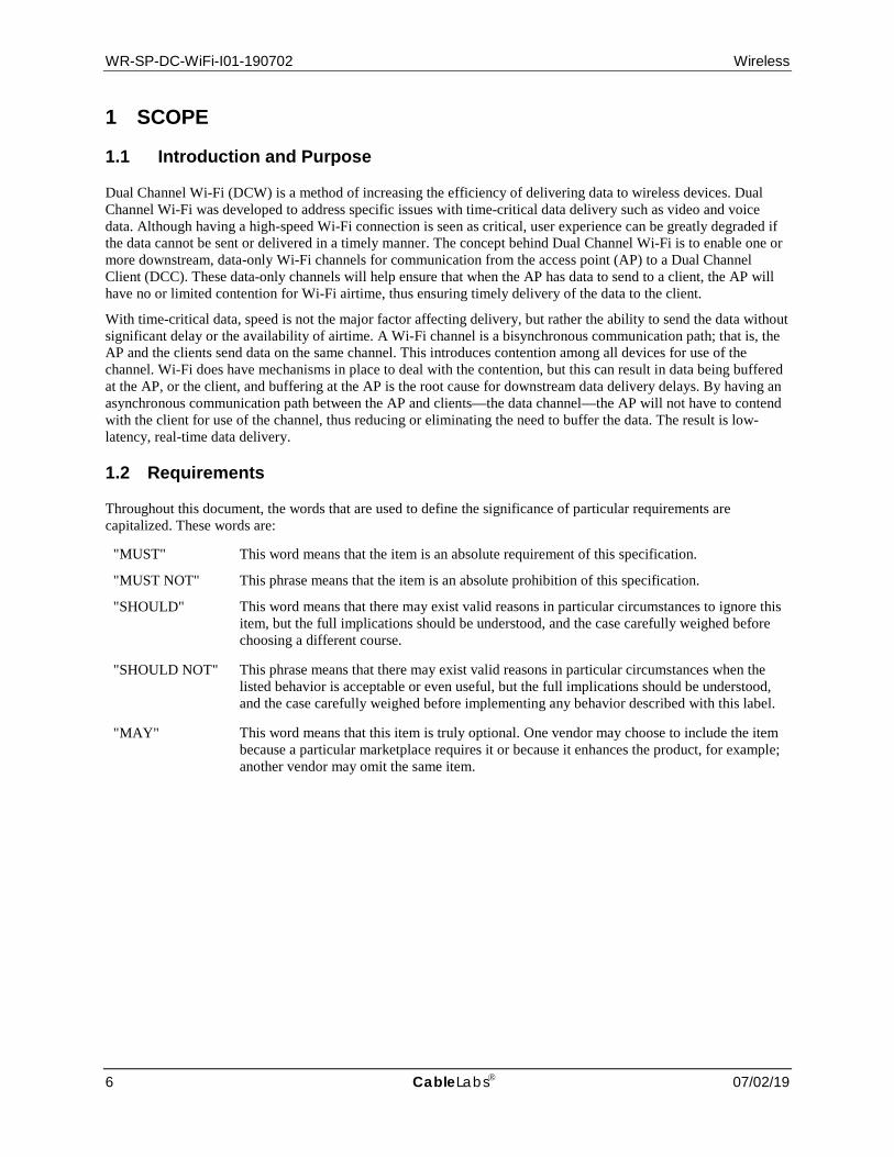
1 SCOPE
1.1 Introduction and Purpose
Dual Channel Wi-Fi (DCW) is a method of increasing the efficiency of delivering data to wireless devices. Dual Channel Wi-Fi was developed to address specific issues with time-critical data delivery such as video and voice data. Although having a high-speed Wi-Fi connection is seen as critical, user experience can be greatly degraded if the data cannot be sent or delivered in a timely manner. The concept behind Dual Channel Wi-Fi is to enable one or more downstream, data-only Wi-Fi channels for communication from the access point (AP) to a Dual Channel Client (DCC). These data-only channels will help ensure that when the AP has data to send to a client, the AP will have no or limited contention for Wi-Fi airtime, thus ensuring timely delivery of the data to the client.
With time-critical data, speed is not the major factor affecting delivery, but rather the ability to send the data without significant delay or the availability of airtime. A Wi-Fi channel is a bisynchronous communication path; that is, the AP and the clients send data on the same channel. This introduces contention among all devices for use of the channel. Wi-Fi does have mechanisms in place to deal with the contention, but this can result in data being buffered at the AP, or the client, and buffering at the AP is the root cause for downstream data delivery delays. By having an asynchronous communication path between the AP and clients—the data channel—the AP will not have to contend with the client for use of the channel, thus reducing or eliminating the need to buffer the data. The result is low-latency, real-time data delivery.
1.2 Requirements
Throughout this document, the words that are used to define the significance of particular requirements are capitalized. These words are:
"MUST" This word means that the item is an absolute requirement of this specification.
"MUST NOT" This phrase means that the item is an absolute prohibition of this specification.
"SHOULD" This word means that there may exist valid reasons in particular circumstances to ignore this item, but the full implications should be understood, and the case carefully weighed before choosing a different course.
"SHOULD NOT" This phrase means that there may exist valid reasons in particular circumstances when the listed behavior is acceptable or even useful, but the full implications should be understood, and the case carefully weighed before implementing any behavior described with this label.
"MAY" This word means that this item is truly optional. One vendor may choose to include the item because a particular marketplace requires it or because it enhances the product, for example; another vendor may omit the same item.

Dual Channel Wi-Fi™ Specification WR-SP-DC-WiFi-I01-190702
7/02/19 CableLabs 7
2 REFERENCES
2.1 Normative References
In order to claim compliance with this specification, it is necessary to conform to the following standards and other works as indicated, in addition to the other requirements of this specification. Notwithstanding, intellectual property rights may be required to use or implement such normative references.
All references are subject to revision, and parties to agreement based on this specification are encouraged to investigate the possibility of applying the most recent editions of the documents listed below.
[802.11] IEEE 802.11-2016, IEEE Standard for Information technology—Telecommunications and information exchange between systems Local and metropolitan area networks—Specific requirements Part 11: Wireless LAN Medium Access Control (MAC) and Physical Layer (PHY) Specifications, December 14, 2016.
2.2 Informative References
This specification does not use any informative references.
2.3 Reference Acquisition
• Cable Television Laboratories, Inc., 858 Coal Creek Circle, Louisville, CO 80027; Phone: +1-303-661-9100; Fax: +1-303-661-9199; http://www.cablelabs.com
• Institute of Electrical and Electronics Engineers (IEEE); Phone: +1-800-422-4633 (USA and Canada); http://www.ieee.org

WR-SP-DC-WiFi-I01-190702 Wireless
8 CableLabs 07/02/19
3 TERMS AND DEFINITIONS This specification uses the following terms.
access point Device that connects the Wi-Fi network and the wired network.
data channel Downstream-only Wi-Fi channel that the AP uses to send data to associated stations/clients.
dual channel client Wi-Fi station/client that has concurrent Wi-Fi channel capabilities. That is, it consists of two or more channels that can be operated at the same time. This device also has the Dual Channel Wi-Fi functionality.
primary channel Normal Wi-Fi channel that the AP and station/client use to communicate.
station/client End device that uses Wi-Fi to connect to the network. For DCW, includes the dual channel client.

Dual Channel Wi-Fi™ Specification WR-SP-DC-WiFi-I01-190702
7/02/19 CableLabs 9
4 ABBREVIATIONS This specification uses the following abbreviations.
AP access point (Wi-Fi)
CL3 CableLabs Layer-3 Protocol
DC data channel
DCC dual channel client
DCW Dual Channel Wi-FiTM
GAS Generic Advertisement Service
GUI graphical user interface
IP Internet Protocol
MAC media access control
PC primary channel
SSID service set identifier
STA station (or client) (Wi-Fi)
WLAN wireless local area network
WR-SP-DC-WiFi-I01-190702 Wireless
10 CableLabs 07/02/19
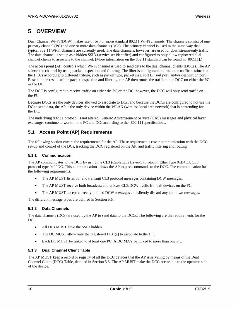
5 OVERVIEW Dual Channel Wi-Fi (DCW) makes use of two or more standard 802.11 Wi-Fi channels. The channels consist of one primary channel (PC) and one or more data channels (DCs). The primary channel is used in the same way that typical 802.11 Wi-Fi channels are currently used. The data channels, however, are used for downstream-only traffic. The data channel is set up as a hidden SSID (service set identifier) and configured to only allow registered dual channel clients to associate to the channel. (More information on the 802.11 standard can be found in [802.11].)
The access point (AP) controls which Wi-Fi channel is used to send data to the dual channel clients (DCCs). The AP selects the channel by using packet inspection and filtering. The filter is configurable to route the traffic destined to the DCCs according to different criteria, such as packet type, packet size, sort IP, sort port, and/or destination port. Based on the results of the packet inspection and filtering, the AP then routes the traffic to the DCC on either the PC or the DC.
The DCC is configured to receive traffic on either the PC or the DC; however, the DCC will only send traffic on the PC.
Because DCCs are the only devices allowed to associate to DCs, and because the DCCs are configured to not use the DC to send data, the AP is the only device within the WLAN (wireless local area network) that is contending for the DC.
The underlying 802.11 protocol is not altered. Generic Advertisement Service (GAS) messages and physical layer exchanges continue to work on the PC and DCs according to the [802.11] specifications.
5.1 Access Point (AP) Requirements
The following section covers the requirements for the AP. These requirements cover communication with the DCC, set-up and control of the DCs, tracking the DCC registered on the AP, and traffic filtering and routing.
5.1.1 Communication The AP communicates to the DCC by using the CL3 (CableLabs Layer-3) protocol, EtherType 0xB4E3, CL3 protocol type 0x00DC. This communication allows the AP to pass commands to the DCC. The communication has the following requirements.
• The AP MUST listen for and transmit CL3 protocol messages containing DCW messages.
• The AP MUST receive both broadcast and unicast CL3/DCW traffic from all devices on the PC.
• The AP MUST accept correctly defined DCW messages and silently discard any unknown messages.
The different message types are defined in Section 5.6.
5.1.2 Data Channels The data channels (DCs) are used by the AP to send data to the DCCs. The following are the requirements for the DC.
• All DCs MUST have the SSID hidden.
• The DC MUST allow only the registered DCC(s) to associate to the DC.
• Each DC MUST be linked to at least one PC. A DC MAY be linked to more than one PC.
5.1.3 Dual Channel Client Table The AP MUST keep a record or registry of all the DCC devices that the AP is servicing by means of the Dual Channel Client (DCC) Table, detailed in Section 5.3. The AP MUST make the DCC accessible to the operator side of the device.

Dual Channel Wi-Fi™ Specification WR-SP-DC-WiFi-I01-190702
7/02/19 CableLabs 11
5.1.4 Traffic Inspection, Filtering, and Routing The AP MUST be able to inspect traffic for all traffic routed to the WLAN.
If the traffic is directed to one of the associated DCCs, then the AP MUST inspect that data packet to determine if the data packet matches one of the filter settings that are applicable to the DCC. If the data packet matches one of the DCC’s applicable filter settings, then the AP MUST use the DC to forward the traffic to the associated DCC. If the data packet does not match one of the DCC’s applicable filter settings, then the AP MUST use the PC to forward the traffic to the associated DCC.
The AP MUST be able to filter on at least the following traffic parameters: protocol type, source IP, source port, destination port, and packet size. Additional traffic parameters may be used depending on traffic filter implementation.
The traffic filter configuration file is detailed in Section 5.4.
5.2 Dual Channel Client (DCC) Requirements
The DCC MUST support the use of two or more concurrent Wi-Fi channels. They can be configured on two separate radios or on a concurrent radio. The following section covers the requirements for the DCC, which includes communication with the AP and traffic routing.
5.2.1 Communication The DCC communicates to the AP by using the CL3 protocol, EtherType 0xB4E3, CL3 protocol type 0x00DC. This communication allows the DCC to request a DC and acknowledge AP responses as well take other commands from the AP. The communication has the following requirements.
• The DCC MUST listen for and transmit CL3 protocol messages containing DCW messages.
• The DCC MUST broadcast DCW messages on the PC when the AP’s MAC address is unknown.
• The DCC MUST filter DCW messages from only the MAC address of the AP that successfully replied to a join, and discard DCW messages from other sources.
• The DCC MUST accept correctly defined DCW messages and silently discard any unknown messages.
The different message types are defined in Section 5.6.
5.2.2 DCC Traffic Routing The DCC MUST accept traffic from the PC and all DCs to which the DCC is associated. The DCC MUST route all upstream traffic over only the PC and not allow any non-802.11 traffic to traverse any DC. Note that all 802.11 response messages are allowed on the DC to ensure correct lower layer operations of the [802.11] protocols.
5.2.3 DCC Auto-connecting to DC SSIDs Due to different connection managers, the DCC may attempt to re-connect to a previously associated DC when the DC is seen by the DCC. In this case, the expected behavior of such actions should result in the association failing based on the AP not having the DCC registered. Whenever the DCC disconnects from a DC, the connection manager should forget the DC to eliminate autoconnections when the DC is seen in the future.
5.3 Dual Channel Client (DCC) Table
The DCC Table is used by the AP to track information on the DCCs registered to the AP. The DCC Table contains the MAC address, the DC(s) assigned to the DCC, the DC(s) that the DCC is connected, and the traffic filter profile in use (Table 1).
When the AP receives an STA_JOIN message from a DCC, the AP MUST determine if there is an entry in the DCC Table for that DCC. If there is already an entry in the DCC Table for the requesting DCC, then the AP MUST use that entry in the table or create a new entry with the same traffic filter profile and delete the old entry. If there is no

WR-SP-DC-WiFi-I01-190702 Wireless
12 CableLabs 07/02/19
entry in the DCC Table for the requesting DCC, then the AP MUST create a new entry and populate it with the default traffic filter profile.
When a DCC disassociates from a DC, the AP MUST delete the entry in the “Associated DC” field in the DCC Table that corresponds to that DCC and DC. This deletion ensures that the AP or users of the DCC Table know that the DCC is no longer associated to that DC and that the DC should not be used to send traffic to the DCC.
Table 1 - DCC Table Headings
DCC MAC Assigned DC(s) Associated DC(s) Traffic Profile
5.4 Traffic Filter Profile
The Traffic Filter Profile defines the filter that determines if traffic destined to a DCC is to be put on the PC or one of the DCs. The AP MUST have one default Traffic Filter Profile named “TFP Default”. The AP MAY have additional Traffic Profile Filters with user-readable names.
The Traffic Filter Profile contains the following fields (Table 2). When using IPv6 addresses as the Source IP/Range, the value is required to be within “[ ]”.
Table 2 - Traffic Filter Profile Fields
Field Name Type Description IP Packet Size Number The length in bytes of the IP data used to match the filter. If the IP data value is
equal to or greater than this value, then the packet is considered a match to the filter. Wildcard is " * "
Source IP/Range IPv4 or IPv6 The source IP used to match the filter; either a single IPv4 address or a single IPv6 address. In the case of IPv4: Range of address using " - " or network mask using " / " In the case of IPv6: Range of address using " - " or mask using " * "
Source Port Number/Range
Ports The source port or port range used to match the filter. In the case of a range, a " - " is used, or it can be comma separated.
Protocol Type Readable Protocols The protocol types used to match the filter. There can be more than one, in which case they are comma separated.
Destination Port Number/Range
Ports The destination port or port range used to match the filter. In the case of a range, a " - " is used, or it can be comma separated.
5.4.1 Example Traffic Filter Profile The format of the Traffic Filter Profile file should be as shown in the sample below.
Format - < IP packet size >:<src ip/range >:<src port number/range>:< protocol type(s) >:<dst port number/range >
IP packet size, Source IP, Layer 4 protocol type and source port number.
e.g. 100:10.0.0.1:tcp:80
e.g. 100:10.0.0.1-10.0.0.255:udp:4000-5000
e.g. 100:10.0:0.1/24:80:tcp:*
Use * to specify any.
e.g. *:*:tcp:6000

Dual Channel Wi-Fi™ Specification WR-SP-DC-WiFi-I01-190702
7/02/19 CableLabs 13
e.g. 100:10.0.0.1:*:3000-4000
Use multiple source values for multiple source filter rules
Maximum 10 rules supported.
Supported Layer 4 protocols: tcp and udp
5.5 Process Flows
This section defines the process flows for the different scenarios by which the AP connects, disconnects, and reassigns DCs to the DCC. See Section 5.7 for summaries of the message flows for these processes.
5.5.1 AP Initialization The AP initialization process is as follows.
• After a factory reset or fresh clean boot, the user configures the PC through any method, such as a web-based graphical user interface (GUI) or command-line interface.
• After configuring the PC, the operator or user then configures one or more DCs. As part of the configuration of the DC, the user links the DCs to one or more PCs.
• The user can then update the default Traffic Filter Profile and add any additional traffic profiles.
• The user can then set known devices to specific traffic profiles.
• The AP MUST retain the PC and DC settings across a restart or reboot of the AP if this is the standard operating procedure of the AP. The AP MUST NOT retain the PC and DC settings upon a factory reset of the AP.
5.5.2 DCC Initialization The DCC associates to a Wi-Fi channel through an SSID manually selected by the user or through an automated function of the DCC, which can use either a previously connected SSID or a feature such as Hotspot 2.0. DCC association uses the following process flow.
• After successfully connecting to the Wi-Fi channel (PC), the DCC MUST start broadcasting STA_JOIN messages at an interval to attempt automatic discovery of the DCW-capable AP. The DCC MUST broadcast STA_JOIN messages that include a list of all the DCC’s DC MAC addresses.
• The AP MUST determine if there is an available DC(s) and, if so, link the DC(s) to the DCC.
• The AP MUST send the DCC an AP_REJECT_STA message if there is no available DC or if the AP is unable to proceed for any reason.
• The AP MUST allow the DCC to associate to the linked DC(s).
• The AP MUST send the DCC an AP_ACCEPT_STA message with the information about the DC(s).
• The AP MUST monitor for the STA_ACK message from the DCC. If the message is not received within the STA_ACK_TIMEOUT time frame, then the AP MUST send the DCC an AP_REJECT_STA message, unlink the DC from the DCC, and not allow the DCC to associate to the DC.
• The DCC MUST attempt to associate to the DC SSID(s) that are included in the AP_ACCEPT_STA message.
• If the DCC is able to successfully complete the association and have the DC(s) fully operational, then the DCC MUST send the AP an STA_ACK message.
• If the DCC is unable to successfully complete the association or have the DC(s) fully operational, then the DCC MUST send the AP an STA_NACK message.
• If the DCC is unable to support a fully operational connection to the DC(s), then the DCC MUST disassociate from any DC(s) to which the DCC is associated.

WR-SP-DC-WiFi-I01-190702 Wireless
14 CableLabs 07/02/19
• When the DCC associates to the DC(s), the AP MUST update the DCC Table to indicate to which DC(s) the DCC is associated.
• The AP MUST NOT transmit traffic destined for the DCC on the DC(s) until it receives the STA_ACK message.
5.5.3 DCC Disconnect If the DCC needs to disconnect from a DC, then the disconnect process is as follows.
• If the DCC needs to disconnect from a DC, the DCC MUST first send the AP the STA_UNJOIN message listing all the DCC’s DC MAC addresses that the DCC is disconnecting.
• When a DCC sends an STA_UNJOIN message, the AP MUST delete the entry in the “Associated DC” field in the DCC Table that corresponds to that DCC and DC(s) and ensure that traffic is no longer flowing to any of the DCC’s listed DC MAC addresses.
• When a DCC sends an STA_UNJOIN message, the AP MUST send the DCC the AP_ACK_DISCONNECT message.
• When the DCC receives the AP_ACK_DISCONNECT message, the DCC MUST disassociate from the DC(s).
• The AP MUST NOT allow the DCC to associate to the DC(s) from which the DCC disconnected until the AP has reissued a new AP_ACCEPT_STA message.
5.5.4 New Downstream Channel If the AP needs to inform a registered DCC of a newly added DC, in order to support use of multiple DCs, then the following actions are performed.
• If the AP needs to inform a registered DCC of a newly added DC, the AP MUST send the currently registered/joined DCC an AP_ACCEPT_STA message listing both the existing connected DC SSID(s) and the newly available DC SSID(s).
• The DCC MAY attempt to associate to the newly available DC(s) included in the AP_ACCEPT_STA message.
• When the DCC associates with the newly available DC(s), the AP MUST update the DCC Table to indicate the DC(s) to which the DCC is associated.
• If the DCC is able to successfully complete the association and have the DC(s) fully operational, then the DCC MUST send the AP an STA_ACK message.
• If the DCC is unable to successfully complete the association or have the DC(s) fully operational, the DCC MUST send the AP an STA_NACK message.
• The AP MUST NOT transmit traffic destined for the DCC on the new DC(s) until it receives the STA_ACK message.
5.5.5 DC Move If the AP determines that a DCC needs to move to a different DC, then the following actions are performed.
• If the AP determines that a DCC needs to move to a different DC, the AP MUST ensure all traffic flowing to the DCC is moved back to the PC.
• If the AP determines that a DCC needs to move to a different DC, the AP MUST send a unicast AP_QUIT message to the DCC.
• When the DCC receives the AP_QUIT message from the AP, the DCC MUST disassociate all DC(s).
• After the DCC disassociates all DC(s), the DCC MUST restart the DCC initialization process, detailed in Section 5.5.2.
Dual Channel Wi-Fi™ Specification WR-SP-DC-WiFi-I01-190702
7/02/19 CableLabs 15
5.5.6 AP PC Disable or Quit When a PC is being disabled or the AP is being reset, the following actions are performed.
• When a PC is being disabled or the AP is being reset, the AP MUST broadcast the AP_QUIT message before disabling the PC.
• After disabling the PC, the AP MUST delete all entries in the “Associated DC” fields in the DCC Table that correspond to that PC and all DCCs associated to it.
• Once the PC is disabled or the AP is reset, the DCC MUST disassociate from all DCs.
5.5.7 AP DC Disable When a DCC is connected to multiple DCs and the AP will disable one or more DCs, the following actions are performed.
• When a DCC is connected to multiple DCs and the AP will disable one or more DCs, the AP MUST ensure all traffic is moved off the DC(s) being disabled.
• The AP MUST send the DCC an AP_ACCEPT_STA message listing only to the active DC(s) that will be available moving forward.
• The DCC MUST disassociate from all DC(s) not listed in the received AP_ACCEPT_STA message.
• The DCC MUST send the AP an STA_ACK message when it has disassociated from the DC(s) not listed.
• The AP MUST delete the entries in the “Assigned DC” and “Associated DC” fields in the DCC Table that correspond to that DCC and the disabled DC(s).
5.6 Message Definitions
The messages that are exchanged between the AP and DCCs are used to control the DCs that a DCC should use. This section defines all the messages that are exchanged and the message types.
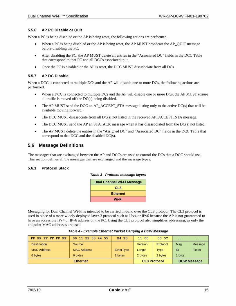
5.6.1 Protocol Stack Table 3 - Protocol message layers
Dual Channel Wi-Fi Message CL3
Ethernet Wi-Fi
Messaging for Dual Channel Wi-Fi is intended to be carried in-band over the CL3 protocol. The CL3 protocol is used in place of a more widely deployed layer-3 protocol such as IPv4 or IPv6 because the AP is not guaranteed to have an accessible IPv4 or IPv6 address on the PC. Using the CL3 protocol also simplifies addressing, as only the endpoint MAC addresses are used.
Table 4 - Example Ethernet Packet Carrying a DCW Message
FF FF FF FF FF FF 00 11 22 33 44 55 B4 E3 11 00 00 DC ... ...
Destination Source Version Protocol Msg Message
MAC Address MAC Address EtherType Length Type ID Fields
6 bytes 6 bytes 2 bytes 2 bytes 2 bytes 1 byte
Ethernet CL3 Protocol DCW Message
WR-SP-DC-WiFi-I01-190702 Wireless
16 CableLabs 07/02/19
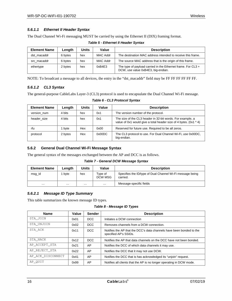
5.6.1.1 Ethernet II Header Syntax
The Dual Channel Wi-Fi messaging MUST be carried by using the Ethernet II (DIX) framing format.
Table 5 - Ethernet II Header Syntax
Element Name Length Units Value Description dst_macaddr 6 bytes hex MAC Addr The destination MAC address intended to receive this frame.
src_macaddr 6 bytes hex MAC Addr The source MAC address that is the origin of this frame.
ethertype 2 bytes hex 0xB4E3 The type of payload carried in the Ethernet frame. For CL3 + DCW, use value 0xB4E3, big-endian.
NOTE: To broadcast a message to all devices, the entry in the “dst_macaddr” field may be FF FF FF FF FF FF.
5.6.1.2 CL3 Syntax
The general-purpose CableLabs Layer-3 (CL3) protocol is used to encapsulate the Dual Channel Wi-Fi message.
Table 6 - CL3 Protocol Syntax
Element Name Length Units Value Description version_num 4 bits hex 0x1 The version number of the protocol.
header_size 4 bits hex 0x1 The size of the CL3 header in 32-bit words. For example, a value of 0x1 would give a total header size of 4 bytes. (0x1 * 4)
rfu 1 byte Hex 0x00 Reserved for future use. Required to be all zeros.
protocol 2 bytes Hex 0x00DC The CL3 protocol to use. For Dual Channel Wi-Fi, use 0x00DC, big-endian.
5.6.2 General Dual Channel Wi-Fi Message Syntax The general syntax of the messages exchanged between the AP and DCC is as follows.
Table 7 - General DCW Message Syntax
Element Name Length Units Value Description msg_id 1 byte hex Type of
DCW MSG Specifies the ID/type of Dual Channel Wi-Fi message being carried.
… … … … Message-specific fields
5.6.2.1 Message ID Type Summary
This table summarizes the known message ID types.
Table 8 - Message ID Types
Name Value Sender Description STA_JOIN 0x01 DCC Initiates a DCW connection STA_UNJOIN 0x02 DCC Removes channels from a DCW connection. STA_ACK 0x11 DCC Notifies the AP that the DCC’s data channels have been bonded to the
specified AP’s SSIDs.
STA_NACK 0x12 DCC Notifies the AP that data channels on the DCC have not been bonded. AP_ACCEPT_STA 0x21 AP Notifies the DCC of which data channels it may use. AP_REJECT_STA 0x22 AP Notifies the DCC that it may not use DCW. AP_ACK_DISCONNECT 0x41 AP Notifies the DCC that is has acknowledged its “unjoin” request. AP_QUIT 0x99 AP Notifies all clients that the AP is no longer operating in DCW mode.

Dual Channel Wi-Fi™ Specification WR-SP-DC-WiFi-I01-190702
7/02/19 CableLabs 17
5.6.3 AP Messages The following messages are generated by the AP.
5.6.3.1 AP_ACCEPT_STA
The AP_ACCEPT_STA message is sent from the AP to the DCC in response to a successful STA_JOIN request.
Table 9 - ap_resp accept
Element Name Length Units Value Description msg_id 1 byte hex 0x21 AP_ACCEPT_STA
num_data_ssid 1 byte hex Count Count of SSID strings that follow this field.
data_ssid_len_1 1 byte hex Length Number of bytes for the SSID string that follows this field.
data_ssid_1 n byte ASCII DC SSID SSID string of the data channel with which the DCC may associate.
data_ssid_len_n 1 byte hex Length Number of bytes for the SSID string that follows this field.
data_ssid_n n bytes ASCII DC SSID SSID string of the data channel with which the DCC may associate.
5.6.3.2 AP_REJECT_STA
The AP_REJECT_STA message is sent from the AP to the DCC in response to an unsuccessful/rejected STA_JOIN request.
Table 10 - ap_resp reject
Element Name Length Units Value Description msg_id 1 byte hex 0x22 AP_REJECT_STA
num_data_macaddr 1 byte hex Count Count of DCC data channel MAC addresses that follow this field. data_macaddr_1 6 bytes hex DCC Data
Macaddr DCC data channel MAC address
data_macaddr_n 6 bytes hex DCC Data Macaddr
DCC data channel MAC address
5.6.3.3 AP_ACK_DISCONNECT
The AP_ACK_DISCONNECT message is sent from the AP to the DCC to acknowledge an STA_UNJOIN message received from the DCC. The AP MUST have removed the associated DC from the DCC Table before sending the AP_ACK_DISCONNECT message.
Table 11 - ap_ack_disconnect
Element Name Length Units Value Description msg_id 1 byte hex 0x41 AP_ACK_DISCONNECT
5.6.3.4 AP_QUIT
The AP_QUIT message is sent from the AP to the DCC to signal that it is stopping all DCW functions. Upon receiving this message, the DCC should disassociate from all DCs.
Table 12 - ap_quit
Element Name Length Units Value Description msg_id 1 byte hex 0x99 AP_QUIT

WR-SP-DC-WiFi-I01-190702 Wireless
18 CableLabs 07/02/19
5.6.4 DCC Messages The following messages are generated by the DCC.
5.6.4.1 STA_JOIN
The STA_JOIN message is the initial message sent from the DCC to the AP to request DCs. The DCC MUST send the STA_JOIN message upon completing a connection to a PC.
Table 13 - sta_join
Element Name Length Units Value Description msg_id 1 byte hex 0x01 STA_JOIN
num_data_macaddr 1 byte hex Count Count of DCC data channel MAC addresses that follow this field
data_macaddr_1 6 bytes hex DCC Data Macaddr
DCC data channel MAC address
data_macaddr_n 6 bytes hex DCC Data Macaddr
DCC data channel MAC address
5.6.4.2 STA_UNJOIN
The STA_UNJOIN message is sent from the DCC to inform the AP that it is disassociating from a DC. This could be the result of an AP-initiated disconnect, a “soft” shutdown, or the DCC determining that the DC is no longer usable.
Table 14 - sta_unjoin
Element Name Length Units Value Description msg_id 1 byte hex 0x02 STA_UNJOIN
num_data_macaddr 1 byte hex Count Count of DCC data channel MAC addresses that follow this field. data_macaddr_1 6 bytes hex DCC Data
Macaddr DCC data channel MAC address
data_macaddr_n 6 bytes hex DCC Data Macaddr
DCC data channel MAC address
5.6.4.3 STA_ACK
The STA_ACK message is sent from the DCC to acknowledge AP messages. The table included in the message is used to inform the AP of successful bonds between certain DCC DC MAC addresses and certain AP SSIDs.
Table 15 - sta_ack
Element Name Length Units Value Description msg_id 1 byte hex 0x11 STA_ACK
num_bonded channel 1 byte hex Count Count of bonded channels that follow this field.
data_macaddr_1 6 bytes hex DCC Data Macaddr
DCC data channel MAC address
data_ssid_len_1 1 byte hex Length Number of bytes for the SSID string that follows this field.
data_ssid_1 n bytes ASCII DC SSID SSID string of the data channel that is bonded to the DCC data channel MAC address.
data_macaddr_n 6 bytes hex DCC Data Macaddr
DCC data channel MAC address
data_ssid_len_n 1 byte hex Length Number of bytes for the SSID string that follows this field.
data_ssid_n n bytes ASCII DC SSID SSID string of the data channel that is bonded to the DCC data channel MAC address.

Dual Channel Wi-Fi™ Specification WR-SP-DC-WiFi-I01-190702
7/02/19 CableLabs 19
5.6.4.4 STA_NACK
The STA_NACK message is sent from the DCC to inform the AP that it has not completed bonding the DCC MAC addresses to the data channel SSIDs provided in the previous ap_resp message (AP_ACCEPT_STA).
Table 16 - sta_nack
Element Name Length Units Value Description msg_id 1 byte hex 0x12 DCWMSG_STA_NACK
num_data_macaddr 1 byte hex Count Count of DCC data channel MAC addresses that follow this field. data_macaddr_1 6 bytes hex DCC Data
Macaddr DCC data channel MAC address
data_macaddr_n 6 bytes hex DCC Data Macaddr
DCC data channel MAC address
5.7 Message Flows
The following subsections summarize the message flows for the processes covered in Section 5.5. The processes include when the DCC starts up from power on or restart, when there is a change in the assigned DCs, when a DCC is disconnecting from the PC, and other scenarios.
5.7.1 DCC Initialization Figure 1 shows the message flow for the process the DCC completes connecting to an SSID. This connection can be through either a manual connection or an automatic connection, such as a preset SSID or Hotspot 2.0.
Figure 1 - DCC Initialization ("Join") Message Flow
STA AP STA_JOIN
AP_ACCEPT_STA
STA_ACK
WR-SP-DC-WiFi-I01-190702 Wireless
20 CableLabs 07/02/19
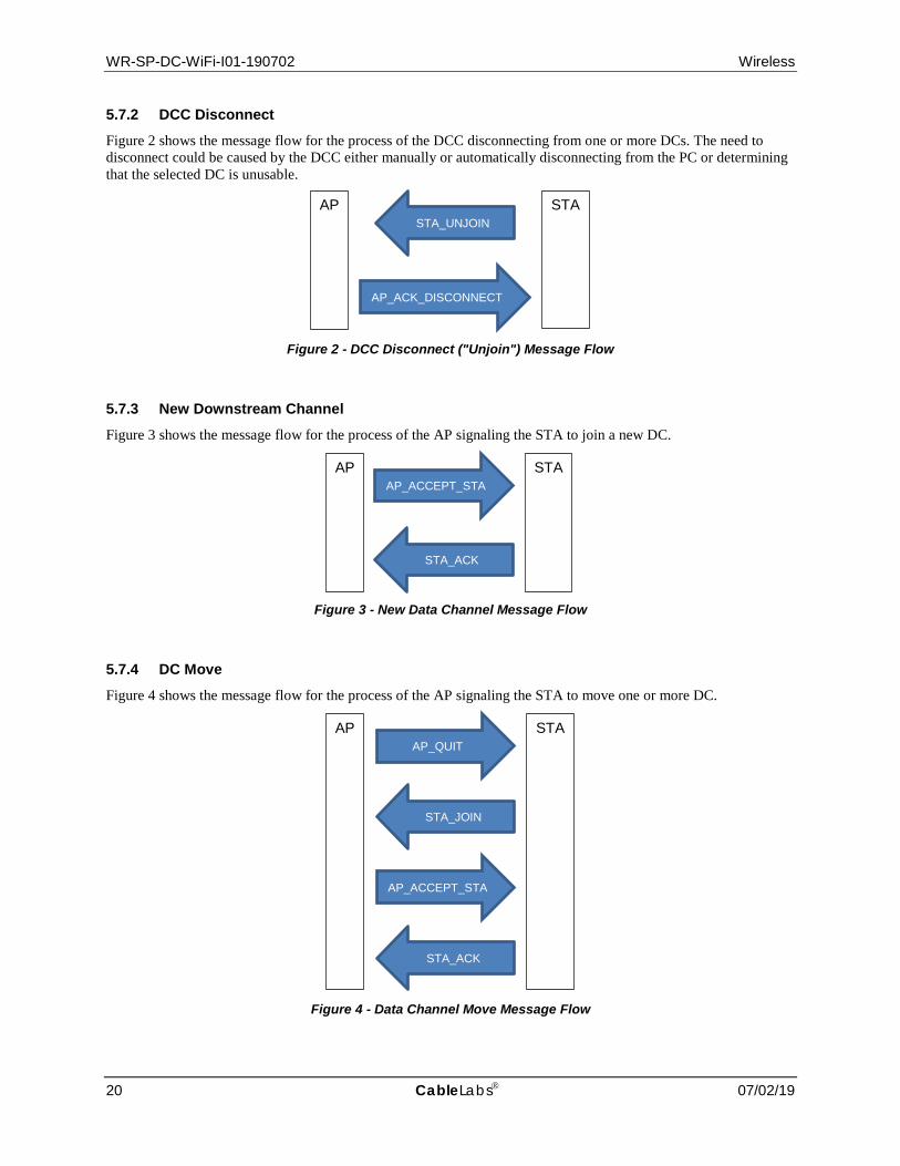
5.7.2 DCC Disconnect Figure 2 shows the message flow for the process of the DCC disconnecting from one or more DCs. The need to disconnect could be caused by the DCC either manually or automatically disconnecting from the PC or determining that the selected DC is unusable.
Figure 2 - DCC Disconnect ("Unjoin") Message Flow
5.7.3 New Downstream Channel Figure 3 shows the message flow for the process of the AP signaling the STA to join a new DC.
Figure 3 - New Data Channel Message Flow
5.7.4 DC Move Figure 4 shows the message flow for the process of the AP signaling the STA to move one or more DC.
Figure 4 - Data Channel Move Message Flow
STA AP STA_UNJOIN
AP_ACK_DISCONNECT
STA AP AP_ACCEPT_STA
STA_ACK
STA AP
AP_ACCEPT_STA
STA_ACK
AP_QUIT
STA_JOIN

Dual Channel Wi-Fi™ Specification WR-SP-DC-WiFi-I01-190702
7/02/19 CableLabs 21
5.7.5 AP PC Disable or Quit Figure 5 shows the message flow for the process of the AP shutting down or resetting.
Figure 5 - AP Disconnect Message Flow
5.7.6 AP DC Disable Figure 6 shows the message flow for the process of disabling a DC.
Figure 6 - DC Disable Message Flow
STA AP
AP_QUIT
STA AP AP_ACCEPT_STA
STA_ACK

WR-SP-DC-WiFi-I01-190702 Wireless
22 CableLabs 07/02/19
Appendix I Acknowledgements (Informative)
We wish to thank the following participants who contributed directly to this document.
Contributor Company Affiliation
Luther Smith CableLabs
Jon Dennis CableLabs
✽ ✽ ✽


![Adobe Photoshop PDF...Access Point LLIJtJ Dual Band Wi-Fi Access Point Wi-Fi Access Point tin] Wi-Fi 97 Wi-Fi AUDIOPHILE VIDEOPHILE nnsW01wa0QnnIWãlluunnunnvvao ñ00f-h01sQIfiðŠ](https://static.fdocuments.us/doc/165x107/5f13acbb3777f75a635fee7f/adobe-photoshop-pdf-access-point-llijtj-dual-band-wi-fi-access-point-wi-fi-access.jpg)