WIRELESS WEATHER STATION - foshk.com user manual.pdftendency between the weather icons. The weather...
12
- 1 - WIRELESS WEATHER STATION INSTRUCTION MANUAL This Operation Manual is part of this product and should be kept in a safe place for future reference. It contains important notes on setup and operation. Page
Transcript of WIRELESS WEATHER STATION - foshk.com user manual.pdftendency between the weather icons. The weather...
- 1 -
WIRELESS WEATHER STATION INSTRUCTION MANUAL
This Operation Manual is part of this product and should be kept in a safe place for future reference. It contains important notes on setup and operation.
Page
- 2 -
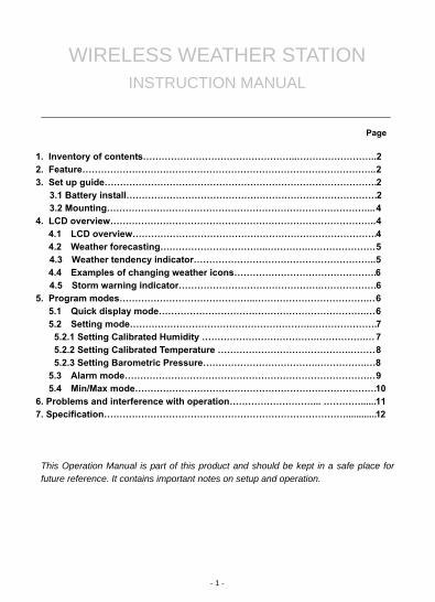
1. Inventory of contents
1) Base station 2) One WH2 remote sensor with mounting bracket 3) Instruction manual 2. Feature
1) Wireless outdoor and indoor humidity (%RH) 2) Wireless outdoor and indoor temperature (°F or °C) 3) Records min. and max. humidity 4) Records min. and max. temperature 5) Barometric pressure 24-hour history graph (inHg or hPa) 6) Weather forecast tendency arrow 7) Forecast icons based on changing barometric pressure 8) DCF radio controlled time and date with manual setting 9) Automatically updates for daylight saving time based on Germany DST system 10) 12 or 24-hour time display 11) Perpetual calendar 12) Time alarm with snooze 13) Can receive one sensor 14) LED backlight 15) Wall hanging or free standing 16) Included transmitter WH2 17) Synchronized instant reception 3. Set up Guide
3.1 Battery install
Note: To avoid operating problems, please take note of battery polarity before/when inserting any Alkaline Batteries (permanent damaged could be introduced by inserting the battery in wrong direction). Use good quality Alkaline Batteries and avoid rechargeable batteries. 1) Insert two AAA batteries into the remote sensor 2) Insert three AA batteries into the weather station. 3) Wait 3 minutes or until the outdoor temperature is displayed in the weather station.
Do not press any keys before outdoor sensor data received. 4) Mount the units, ensuring that the receiver can still pick up the signal from the transmitter. To measure outdoor temperature, place the transmitter outdoors. It will transmit the temperature from its location. Every time the remote sensor is powered up (for example after a change of batteries), a random security code is transmitted and this code must be synchronized with the base station to receive weather data. Thus if battery change happened on transmitter side, then the receiver must be power up again to re-learn the transmitter.
- 3 -
After the remote sensor is powered up, the sensor will transmit weather data every 8s for 6 times. After this learning period is over, then the transmitter will transmit every 48s. When the base station is powered up, a short beep will sound and all LCD segments will light up for about 3 seconds before it enters into learning mode to learn the sensors security code. After the learning mode, the base station will start the DCF
radio controlled time reception and the RCC search icon will turn on. During the
RCC time reception period (maximum 10 minutes), no weather data will be transmitted to avoid interference. If RCC signal can’t be found within1 minutes, the signal search will be cancelled and will automatically resume every two hours until the signal is successfully captured. Regular RF link will be established once RCC reception routine is finished. Once the radio controlled time is received the DCF icon will be present above the time Note: DO NOT PRESS ANY KEY during the first 3 minutes learning period. After both indoor and outdoor data are displayed you can place your remote sensor outdoors and set your time (if no RCC reception is possible). If there is no temperature reading in the indoor station, make sure the units are within range of each other or repeat the battery installation procedure. If a key is pressed before the weather station receives the temperature signal, you will need to follow the battery installation procedure again. Please wait 10seconds before re-insert the battery again to make a proper reset for both transmitter and receiver. Note for Radio Controlled Time: The time and date display is based on the signal provided by the highly accurate government operated atomic clock. The base station will continue to scan for the radio controlled time signal each day despite it being manually set. If reception has been unsuccessful, then the radio controlled time icon will not appear but reception will still be attempted continually. If reception has been successful, the received time and date will overwrite the manually set time and date.
Note: Please participate in the preservation of the environment by properly disposing of all used-up batteries and accumulators at designated disposal points. Never dispose of batteries in a fire as this may cause explosion, risk of fire or leakage of dangerous chemicals and fumes
- 4 -
3.2 Mounting
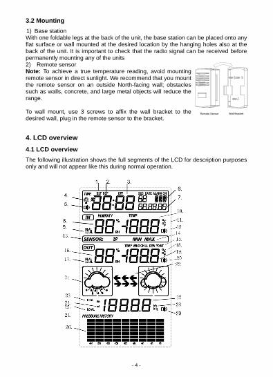
1) Base station With one foldable legs at the back of the unit, the base station can be placed onto any flat surface or wall mounted at the desired location by the hanging holes also at the back of the unit. It is important to check that the radio signal can be received before permanently mounting any of the units 2) Remote sensor Note: To achieve a true temperature reading, avoid mounting remote sensor in direct sunlight. We recommend that you mount the remote sensor on an outside North-facing wall; obstacles such as walls, concrete, and large metal objects will reduce the range. To wall mount, use 3 screws to affix the wall bracket to the desired wall, plug in the remote sensor to the bracket.
4. LCD overview 4.1 LCD overview
The following illustration shows the full segments of the LCD for description purposes only and will not appear like this during normal operation.
- 5 -
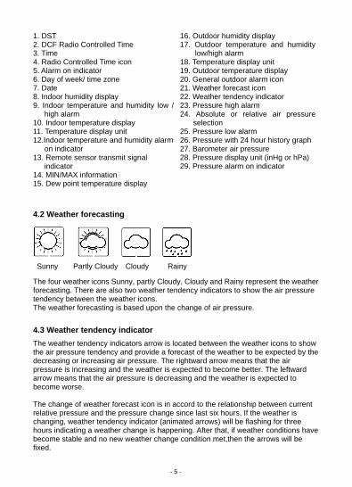
1. DST 2. DCF Radio Controlled Time 3. Time 4. Radio Controlled Time icon 5. Alarm on indicator 6. Day of week/ time zone 7. Date 8. Indoor humidity display 9. Indoor temperature and humidity low /
high alarm 10. Indoor temperature display 11. Temperature display unit 12.Indoor temperature and humidity alarm
on indicator 13. Remote sensor transmit signal
indicator 14. MIN/MAX information 15. Dew point temperature display
16. Outdoor humidity display 17. Outdoor temperature and humidity
low/high alarm 18. Temperature display unit 19. Outdoor temperature display 20. General outdoor alarm icon 21. Weather forecast icon 22. Weather tendency indicator 23. Pressure high alarm 24. Absolute or relative air pressure
selection 25. Pressure low alarm 26. Pressure with 24 hour history graph 27. Barometer air pressure 28. Pressure display unit (inHg or hPa) 29. Pressure alarm on indicator
4.2 Weather forecasting
Sunny Partly Cloudy Cloudy Rainy The four weather icons Sunny, partly Cloudy, Cloudy and Rainy represent the weather forecasting. There are also two weather tendency indicators to show the air pressure tendency between the weather icons. The weather forecasting is based upon the change of air pressure.
4.3 Weather tendency indicator
The weather tendency indicators arrow is located between the weather icons to show the air pressure tendency and provide a forecast of the weather to be expected by the decreasing or increasing air pressure. The rightward arrow means that the air pressure is increasing and the weather is expected to become better. The leftward arrow means that the air pressure is decreasing and the weather is expected to become worse. The change of weather forecast icon is in accord to the relationship between current relative pressure and the pressure change since last six hours. If the weather is changing, weather tendency indicator (animated arrows) will be flashing for three hours indicating a weather change is happening. After that, if weather conditions have become stable and no new weather change condition met,then the arrows will be fixed.
6
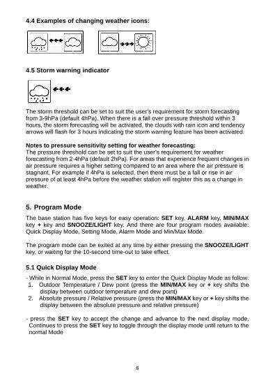
4.4 Examples of changing weather icons:
4.5 Storm warning indicator
The storm threshold can be set to suit the user’s requirement for storm forecasting from 3-9hPa (default 4hPa). When there is a fall over pressure threshold within 3 hours, the storm forecasting will be activated, the clouds with rain icon and tendency arrows will flash for 3 hours indicating the storm warning feature has been activated. Notes to pressure sensitivity setting for weather forecasting: The pressure threshold can be set to suit the user’s requirement for weather forecasting from 2-4hPa (default 2hPa). For areas that experience frequent changes in air pressure requires a higher setting compared to an area where the air pressure is stagnant. For example if 4hPa is selected, then there must be a fall or rise in air pressure of at least 4hPa before the weather station will register this as a change in weather.
5. Program Mode
The base station has five keys for easy operation: SET key, ALARM key, MIN/MAX key + key and SNOOZE/LIGHT key. And there are four program modes available: Quick Display Mode, Setting Mode, Alarm Mode and Min/Max Mode. The program mode can be exited at any time by either pressing the SNOOZE/LIGHT key, or waiting for the 10-second time-out to take effect.
5.1 Quick Display Mode
- While in Normal Mode, press the SET key to enter the Quick Display Mode as follow: 1. Outdoor Temperature / Dew point (press the MIN/MAX key or + key shifts the
display between outdoor temperature and dew point) 2. Absolute pressure / Relative pressure (press the MIN/MAX key or + key shifts the
display between the absolute pressure and relative pressure) - press the SET key to accept the change and advance to the next display mode. Continues to press the SET key to toggle through the display mode until return to the normal Mode
- 7 -
5.2 Setting Modes
- Press the SET key for 3 second while in normal mode to enter the normal Setting mode
- Press the SET key to select the following setting in sequence : 1) Time Zone Setting
The default time zone setting value is 0 base on Germany DCF time (GMT+1) 2) 12/24 hour format
3) Manual time setting (hours/minutes) 4) Calendar setting (year /month /date) 5) Temperature display unit degree Celsius or Fahrenheit 6) Indoor humidity calibration 7) Outdoor humidity calibration 8) Air pressure display units in hPa or inHg 9) Relative pressure setting from 919.0hPa – 1080.0hPa (default 1013.5hPa) 10) Pressure threshold setting (default 2hPa)
11) Storm threshold setting (default 4hPa)
- In the setting modes, press + key or MIN/MAX key change or scrolls the value. Hold the +key or MIN/MAX key for 3 second will increase/decrease digits in great steps.
- Press SNOOZE/LIGHT key or key idle 10 second, the setting mode will return to Normal Mode
Note: Please set the units firstly before change units’ value. During change of units setting, units’ value will change according to new units but it might cause resolution loss due to its internal calculation algorithm. 5.2.1 Setting Calibrated Humidity
The display console allows you to calibrate both the indoor and outdoor humidity. Humidity is a difficult parameter to measure accurately and drifts over time. The calibration feature allows you to zero out this error. To calibrate humidity, you will need an accurate source, such as a sling psychrometer or Humidipaks One Step Calibration kit.
To calibrate indoor humidity, in the Set Mode with indoor humidity flashing, press the +
key or MIN/MAX key to increase or decrease the humidity setting (in increments of 1%) to match the calibrated or known humidity source. To return the indoor humidity to the measured value, press and hold the SET key for 3 seconds and the humidity will return to the uncalibrated value. To calibrate outdoor humidity, in the Set Mode with outdoor humidity flashing, press
the + key or MIN/MAX key to increase or decrease the humidity setting (in increments
of 1%) to match the calibrated or known humidity source. To return the outdoor humidity to the measured value, press and hold the SET key for 3 seconds and the humidity will return to the uncalibrated value.
- 8 -
Note: The remote (outdoor) thermo-hygrometer will always display the measured humidity level and not the calibrated humidity level. Only the console will show the calibrated value. Note: The dew point calculation is based on the calibrated humidity level. 5.2.2 Setting Calibrated Temperature
Temperature is measured by a resistive thermal device (RTD) and is subject to electronic variation. Temperature errors can also occur when a sensor is placed too close to a heat source (such as a building structure, the ground or trees). To calibrate the indoor or outdoor temperature, we recommend a mercury or red spirit (fluid) thermometer. Bi-metal (dia) and other digital thermometers are not a good source and have their own margin of error. Using a local weather station in your area is also a poor source due to changes in location, timing (airport weather stations are only updated once per hour) and possible calibration errors (many official weather stations are not properly installed and calibrated). Place the sensor in a shaded, controlled environment next to the fluid thermometer, and allow the sensor to stabilize for 24 hours. Compare this temperature to the fluid thermometer and adjust the console to match the fluid thermometer. To calibrate indoor or outdoor temperature, in the Set Mode with indoor or outdoor
temperature flashing, press the + key or MIN/MAX key to increase or decrease the
temperature setting (in increments of 0.1 degC or 0.18 degF) to match the calibrated or known temperature source. Note: The remote (outdoor) thermo-hygrometer will always display the measured temperature level and not the calibrated temperature level. Only the console will show the calibrated value. Note: The dew point calculation is based on the calibrated temperature level.
5.2.3 Setting Barometric Pressure
The display console displays two different pressures: absolute (measured) and relative (corrected to sea-level). To compare pressure conditions from one location to another, meteorologists correct pressure to sea-level conditions. Because the air pressure decreases as you rise in altitude, the sea-level corrected pressure (the pressure your location would be at if located at sea-level) is generally higher than your measured pressure. Thus, your absolute pressure may read 28.62 inHg (969 mb) at an altitude of 1000 feet (305 m), but the relative pressure is 30.00 inHg (1016 mb).
- 9 -
The standard sea-level pressure is 29.92 in Hg (1013 mb). This is the average sea-level pressure around the world. Relative pressure measurements greater than 29.92 inHg (1013 mb) are considered high pressure and relative pressure measurements less than 29.92 inHg are considered low pressure. To determine the relative pressure for your location, locate an official reporting station near you (the internet is the best source for real time barometer conditions, such as Weather.com or Wunderground.com), and set your weather station to match the official reporting station.
To change the relative pressure is flashing, press the + key or MIN/MAX key to
increase or decrease the relative pressure setting to match the official reporting station.
5.3 Alarm Modes
- While in Normal Mode press the ALARM key to enter the High Alarm Mode - Press the ALARM key again to enter Low Alarm mode
Remark: after the initial pressing of ALARM key, the display will be refreshed to show current high, low alarm value. Normal alarm value will be displayed only for those already activated, all other not activated values will be displayed with “---“or”--“instead.
- Press the ALARM key again to return the Normal Mode - In the High Alarm Mode press the SET key to select the following alarm modes:
1. Time alarm (hour/minute) 2. Indoor humidity high alarm 3. Indoor temperature high alarm 4. Outdoor humidity high alarm 5. Outdoor temperature and dew point high alarm 6. Pressure high alarm
- In the Low Alarm Mode press the SET key to select the following alarm modes:
1. Time alarm (hour/minute) 2. Indoor humidity low alarm 3. Indoor temperature low alarm 4. Outdoor humidity low alarm 5. Outdoor temperature and dew point low alarm 6. Pressure low alarm
- In the alarm modes, Press + key or MIN/MAX key change or scrolls the alarm value. Hold the + key or MIN/MAX key for 3 second to change the number in great step. Press the ALARM key to choose the alarm on or off (if alarm is enabled, the speaker icon on the LCD will be turned on indicating the alarm function has been enabled). Press the SET key to confirm the setting and continue pressing the SET key to toggle through each alarm mode until it returns to the normal display mode.
- Press SNOOZE/LIGHT key or key idle 10 second at any time, the alarm mode will return to Normal Mode
- 10 -
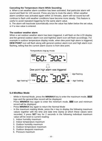
Canceling the Temperature Alarm While Sounding a. When a set weather alarm condition has been activated, that particular alarm will sound and flash for 120 second. Press any key to mute the alarm. When weather alarm condition was activated again within 10 minutes, alarm will not sound but will continue to flash until weather conditions have become more steady. This feature is useful to avoid repeated triggering for the same alarm value. b. The alarm will reactivate automatically once the value has fallen below the set value, or if a new value is entered. The outdoor weather alarm When a set outdoor weather alarm has been triggered, it will flash on the LCD display and the general outdoor alarm icon and high/low alarm icon will flash accordingly. For example in outdoor temperature display mode, when dew point high alarm is triggered, DEW POINT icon will flash along with general outdoor alarm icon and high alarm icon flashing, telling that the current alarm source is from dew point.
5.4 Min/Max Mode
- While in Normal Mode, press the MIN/MAX key to enter the maximum mode, MAX logo and the general Max record will be displayed.
- Press MIN/MAX key again to enter the minimum mode, MIN icon and minimum record will be displayed
- Press MIN/MAX key again to return the Normal Mode - In the maximum reading Mode, press the + key to display the following maximum
values together with the time and date time stamp at which these values were recorded, if press SET key for 2 seconds in the following individual maximum value will be reset to current reading:
1. Indoor humidity maximum 2. Indoor temperature maximum 3. Outdoor humidity maximum 4. Outdoor temperature maximum 5. Outdoor dewpoint maximum 6. Pressure maximum
- 11 -
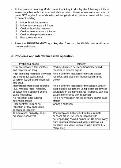
- In the minimum reading Mode, press the + key to display the following minimum values together with the time and date at which these values were recorded, if press SET key for 2 seconds in the following individual minimum value will be reset to current reading:
1. Indoor humidity minimum 2. Indoor temperature minimum 3. Outdoor humidity minimum 4. Outdoor temperature minimum 5. Outdoor dewpoint minimum 6. Pressure minimum
- Press the SNOOZE/LIGHT key or key idle 10 second, the Min/Max mode will return to Normal Mode
6. Problems and interference with operation
Problem & cause Remedy
Distance between transmitters and receiver too long
Reduce distance between transmitters and receiver to receive signal
High shielding materials between the units (thick walls, steel, concrete, isolating aluminum foil and etc.)
Find a different location for sensors and/or receiver. See also item ‘transmission range’ below
Interference from other sources (e.g. wireless radio, headset, speaker, etc. operating on the same frequency)
Find a different location for the sensors and/or base station. Neighbors using electrical devices operation on the same signal frequency can also cause interference with reception
No reception after adding extension cables
Find a new location for the sensors and/or base station.
Poor contrast LCD or no reception or low batteries in sensors or receiver
Change batteries
Temperature, humidity, or air pressure is incorrect.
Check/replace batteries. If multiple remote sensors are in use, check location with corresponding “boxed numbers”. Or move away from sources of heat/cold. Adjust relative air pressure to a value from a reliable source (TV radio, etc.).
- 12 -