Wireless technologies - Part 2
135
01/21/22 Tinniam V Ganesh 1 01/21/22 1 http:// gigadom.wordpress.com Tinniam.V.Ganesh
-
Upload
tinniam-v-ganesh-tv -
Category
Technology
-
view
3.020 -
download
5
Transcript of Wireless technologies - Part 2

04/18/23 Tinniam V Ganesh 104/18/23 1
http://gigadom.wordpress.com
Tinniam.V.Ganesh

04/18/23 Tinniam V Ganesh 2
Agenda
• Network Architecture, Network Elements• Typical 2G Architecture• PLMN, CS, PS, AN,CN• MSC, HLR, VLR• GMSC, AuC, EIR• 2.5 G Architecture• SGSN, GGSN• Recap• SMS Architecture• SMS Network Elements• 3G Network Architecture• Frequency reuse• Handoff• Bluetooth stack• WiFI• Recap• Quiz 3
04/18/23 2

04/18/23 Tinniam V Ganesh 3
Evolution of Technology
04/18/23 3

04/18/23 Tinniam V Ganesh 4
Typical 2G Architecture
04/18/23 4

04/18/23 Tinniam V Ganesh 5
Signaling in Core Network
Based on SS7• ISUP and specific Application PartsGSM MAP and ANSI-41 services• Mobility, call-handling, O&M• Authentication, supplementary services• SMS, …Location registers for mobility management• HLR: home location register has permanent data• VLR: visitor location register keeps local copy for roamer
04/18/23 5

04/18/23 Tinniam V Ganesh 6
GSM 2G Architecture
04/18/23 6
04/18/23 Tinniam V Ganesh 7
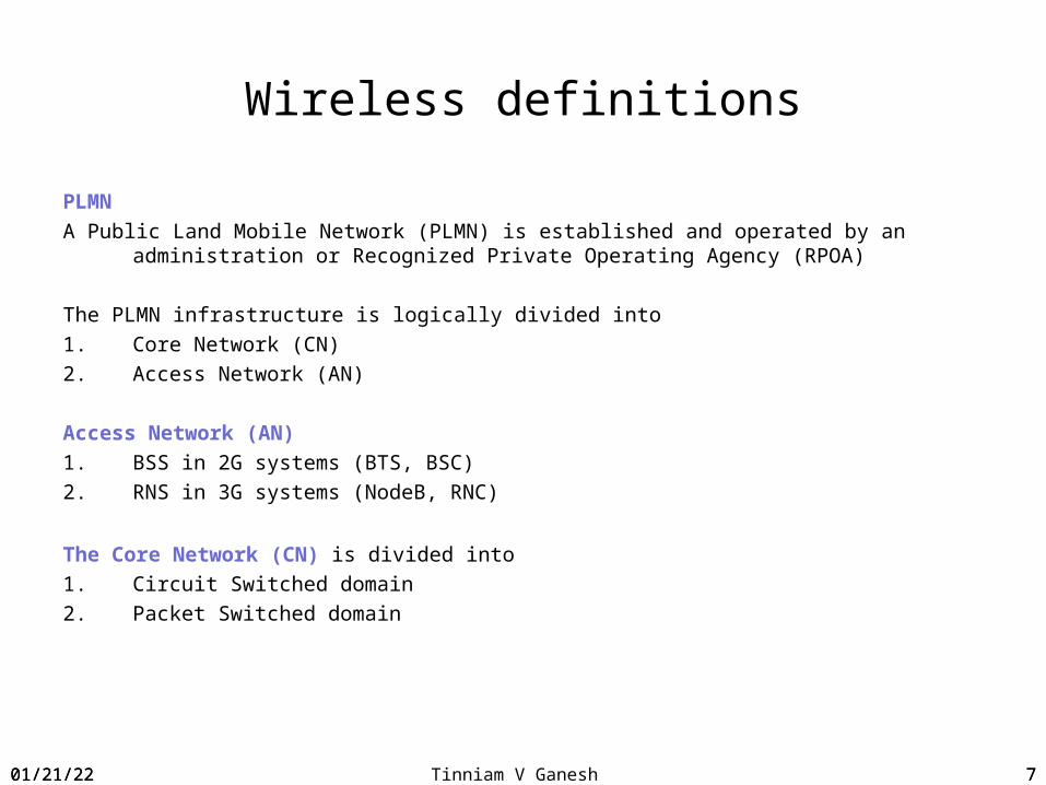
Wireless definitions
PLMN A Public Land Mobile Network (PLMN) is established and operated by an administration or
Recognized Private Operating Agency (RPOA)
The PLMN infrastructure is logically divided into 1. Core Network (CN) 2. Access Network (AN)
Access Network (AN)1. BSS in 2G systems (BTS, BSC)2. RNS in 3G systems (NodeB, RNC)
The Core Network (CN) is divided into1. Circuit Switched domain2. Packet Switched domain
04/18/23 7

04/18/23 Tinniam V Ganesh 8
PLMN Circuit Switched (CS) domainAccess Network – BTS, BSCCore Network - MSC, VLR, HLR, GMSC, SMSC
Packet Switched (PS) domainAccess Network – BTS, BSCCore network - SGSN, GGSN
04/18/23 8

04/18/23 Tinniam V Ganesh 9
GSM Architecture
Access Network1. BTS2. BSC
Core Network1. MSC2. HLR3. VLR4. AuC5. EIR6. SMSC7. GMSC
04/18/23 9
04/18/23 Tinniam V Ganesh 10
GSM- Access Network
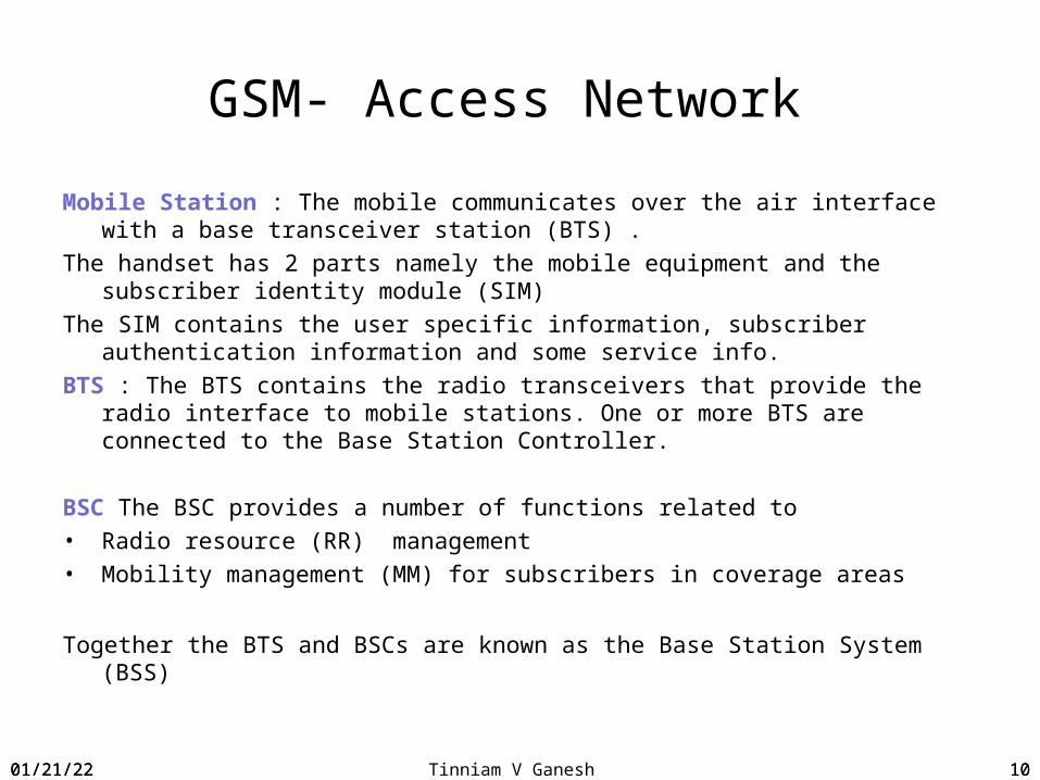
Mobile Station : The mobile communicates over the air interface with a base transceiver station (BTS) .
The handset has 2 parts namely the mobile equipment and the subscriber identity module (SIM)
The SIM contains the user specific information, subscriber authentication information and some service info.
BTS : The BTS contains the radio transceivers that provide the radio interface to mobile stations. One or more BTS are connected to the Base Station Controller.
BSC The BSC provides a number of functions related to• Radio resource (RR) management • Mobility management (MM) for subscribers in coverage areas
Together the BTS and BSCs are known as the Base Station System (BSS)
04/18/23 10
04/18/23 Tinniam V Ganesh 11
Mobile Switching Center (MSC)
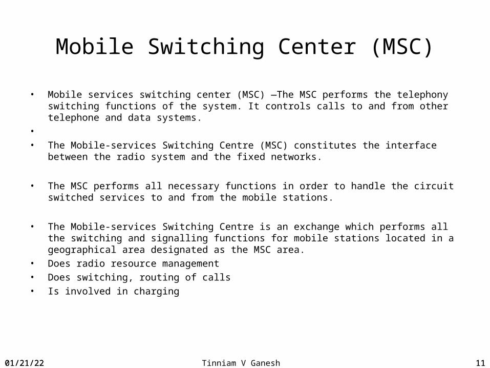
• Mobile services switching center (MSC) —The MSC performs the telephony switching functions of the system. It controls calls to and from other telephone and data systems.
• • The Mobile-services Switching Centre (MSC) constitutes the interface between the
radio system and the fixed networks.
• The MSC performs all necessary functions in order to handle the circuit switched services to and from the mobile stations.
• The Mobile-services Switching Centre is an exchange which performs all the switching and signalling functions for mobile stations located in a geographical area designated as the MSC area.
• Does radio resource management• Does switching, routing of calls• Is involved in charging
04/18/23 11
04/18/23 Tinniam V Ganesh 12
Home Location Register (HLR)
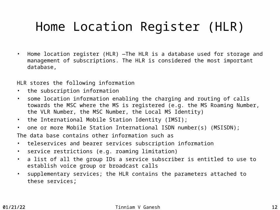
• Home location register (HLR) —The HLR is a database used for storage and management of subscriptions. The HLR is considered the most important database,
HLR stores the following information• the subscription information• some location information enabling the charging and routing of calls towards the MSC
where the MS is registered (e.g. the MS Roaming Number, the VLR Number, the MSC Number, the Local MS Identity)
• the International Mobile Station Identity (IMSI);• one or more Mobile Station International ISDN number(s) (MSISDN);The data base contains other information such as• teleservices and bearer services subscription information• service restrictions (e.g. roaming limitation)• a list of all the group IDs a service subscriber is entitled to use to establish voice
group or broadcast calls
• supplementary services; the HLR contains the parameters attached to these services;
04/18/23 12

04/18/23 Tinniam V Ganesh 13
Visitor Location Register (VLR)
• Visitor location register (VLR) —The VLR is a database that contains temporary information about subscribers that is needed by the MSC in order to service visiting subscribers.
• The VLR is always integrated with the MSC. • When a mobile station roams into a new MSC area, the VLR connected to that MSC
will request data about the mobile station from the HLR. • Later, if the mobile station makes a call, the VLR will have the information needed for
call setup without having to interrogate the HLR each time.
• The VLR stores the following information
- the International Mobile Subscriber Identity (IMSI);- the Mobile Station International ISDN number (MSISDN);- the Mobile Station Roaming Number (MSRN), - the Temporary Mobile Station Identity (TMSI), if applicable;
04/18/23 13
04/18/23 Tinniam V Ganesh 14
Authentication Center (AuC)
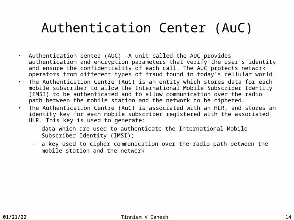
• Authentication center (AUC) —A unit called the AUC provides authentication and encryption parameters that verify the user's identity and ensure the confidentiality of each call. The AUC protects network operators from different types of fraud found in today's cellular world.
• The Authentication Centre (AuC) is an entity which stores data for each mobile subscriber to allow the International Mobile Subscriber Identity (IMSI) to be authenticated and to allow communication over the radio path between the mobile station and the network to be ciphered.
• The Authentication Centre (AuC) is associated with an HLR, and stores an identity key for each mobile subscriber registered with the associated HLR. This key is used to generate:
– data which are used to authenticate the International Mobile Subscriber Identity (IMSI);
– a key used to cipher communication over the radio path between the mobile station and the network
04/18/23 14
04/18/23 Tinniam V Ganesh 15
Equipment Identification Register (EIR)
• Equipment identity register (EIR) —The EIR is a database that contains information about the identity of mobile equipment that prevents calls from stolen, unauthorized, or defective mobile stations. The AUC and EIR are implemented as stand-alone nodes or as a combined AUC/EIR node.
• The Equipment Identity Register (EIR) in the GSM system is the logical entity which is responsible for storing in the network the International Mobile Equipment Identities (IMEIs), used in the GSM system.
04/18/23 15
04/18/23 Tinniam V Ganesh 16
Gateway MSC (GMSC)
• If a network delivering a call to the PLMN cannot interrogate the HLR, the call is routed to an MSC. This MSC will interrogate the appropriate HLR and then route the call to the MSC where the mobile station is located. The MSC which performs the routing function to the actual location of the MS is called the Gateway MSC (GMSC).
04/18/23 16

04/18/23 Tinniam V Ganesh 1704/18/23 17

04/18/23 Tinniam V Ganesh 18
2.5G Architectural details
04/18/23 18
04/18/23 Tinniam V Ganesh 19
General Packet Radio Service (GPRS)
Core Network• Serving GPRS Support Node (SGSN)• Gateway GPRS Support Node (GGSN)
04/18/23 19
04/18/23 Tinniam V Ganesh 20
Serving GPRS Support Node (SGSN)A Serving GPRS Support Node (SGSN) is responsible for the delivery of data packets from and to the mobile stations within its geographical
service area. packet routing and transfer, mobility management (attach/detach and location management), logical link management, and authentication charging functions.
The location register of the SGSN stores location information current cell, current VLR user profiles (e.g., IMSI, address(es) used in the packet data network) of all GPRS
users registered with this SGSN.
04/18/23 20
04/18/23 Tinniam V Ganesh 21
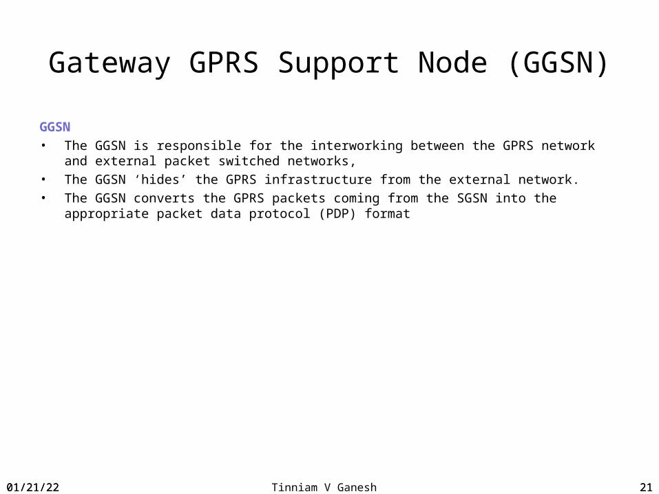
Gateway GPRS Support Node (GGSN)
GGSN• The GGSN is responsible for the interworking between the GPRS network and
external packet switched networks, • The GGSN ‘hides’ the GPRS infrastructure from the external network.• The GGSN converts the GPRS packets coming from the SGSN into the appropriate
packet data protocol (PDP) format
04/18/23 21

04/18/23 Tinniam V Ganesh 22
GSM Evolution for Data Access
04/18/23 22

04/18/23 Tinniam V Ganesh 2304/18/23 23

04/18/23 Tinniam V Ganesh 24
SMS Architecture
SC MSC/SGSN MSSMS-GMSC /SMS-IWMSC
HLR VLR
< >> >< <
1. 3. 5.
2. 4.*
< <
SC – Service Centre
SMS-IWMSC – SMS Interworking MSC
SMS-GMSC – Gateway MSC for SMS
04/18/23 24

04/18/23 Tinniam V Ganesh 25
SMS Network Elements
• Service Centre (SC): function responsible for the relaying and store‑and‑forwarding of a short message between an SME and an MS
• Gateway MSC For Short Message Service (SMS‑GMSC): function of an MSC capable of receiving a short message from an SC, interrogating an HLR for routing information and SMS info, and delivering the short message to the VMSC or the SGSN of the recipient MS
• Interworking MSC For Short Message Service (SMS‑IWMSC): function of an MSC capable of receiving a short message from within the PLMN and submitting it to the recipient SC
04/18/23 25
04/18/23 Tinniam V Ganesh 26
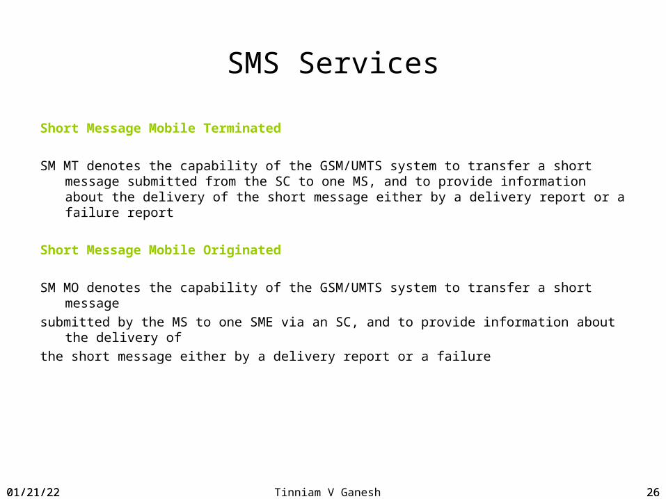
SMS Services
Short Message Mobile Terminated
SM MT denotes the capability of the GSM/UMTS system to transfer a short message submitted from the SC to one MS, and to provide information about the delivery of the short message either by a delivery report or a failure report
Short Message Mobile Originated
SM MO denotes the capability of the GSM/UMTS system to transfer a short messagesubmitted by the MS to one SME via an SC, and to provide information about the delivery
ofthe short message either by a delivery report or a failure
04/18/23 26
04/18/23 Tinniam V Ganesh 27
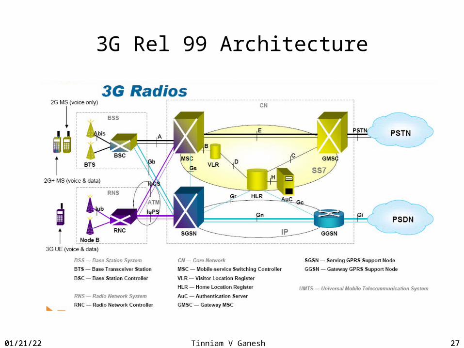
3G Rel 99 Architecture
04/18/23 27

04/18/23 Tinniam V Ganesh 28
3G ArchitectureAccess Network Universal Terrestial Radio Access NetworkRadio Network Systems (RNS) or UTRAN1. Node B2. Radio Network Controller RNC
Core Network1. MSC Server (UMTS)2. HLR3. VLR4. GMSC5. SMSC
04/18/23 28
04/18/23 Tinniam V Ganesh 29
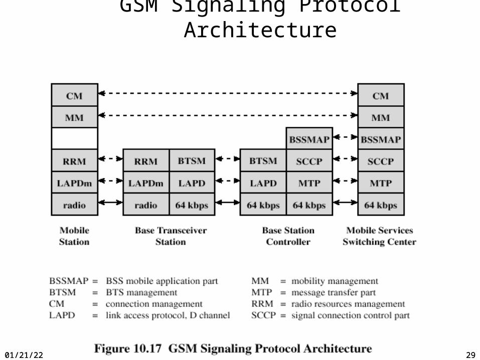
GSM Signaling Protocol Architecture
04/18/23 29
04/18/23Tinniam V Ganesh 30
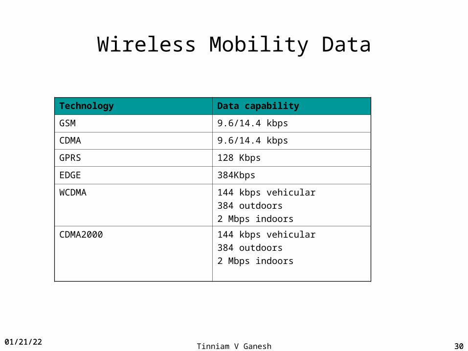
Wireless Mobility Data
Technology Data capability
GSM 9.6/14.4 kbps
CDMA 9.6/14.4 kbps
GPRS 128 Kbps
EDGE 384Kbps
WCDMA 144 kbps vehicular384 outdoors2 Mbps indoors
CDMA2000 144 kbps vehicular384 outdoors2 Mbps indoors
04/18/2330
04/18/23 Tinniam V Ganesh 31
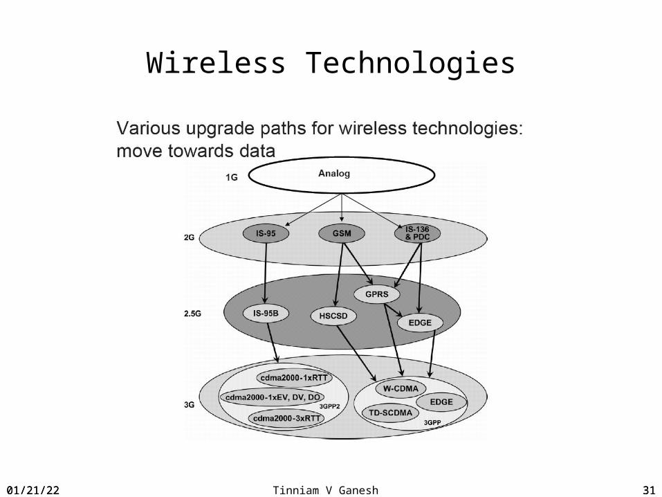
Wireless Technologies
04/18/23 31
04/18/23 Tinniam V Ganesh 3204/18/23 32
Optimizing Frequency reuse

04/18/23 Tinniam V Ganesh 33
Access Network
• The network is divided into a number of cells or geographic coverage areas• Within each cell is a base station which contains the radio transmission and
reception equipments• The coverage area of the base station depends in factors like transmit
power of station, the height of the base station the topology of the area.• Specific radio frequencies are allocated within each cell • The frequencies are reused in other cells that are sufficiently far away to
avoid interference
04/18/23 33

04/18/23 Tinniam V Ganesh 34
Problem due to limited spectrum
Spectrum allocation at 800 Mhz – 25 Mhz1G AMPS systems – 30 Khz/channelCapacity = 25 Mhz/30Khz = 833 channelsHence 833 simultaneous users (hardly enough)
04/18/23 34

04/18/23 Tinniam V Ganesh 35
Frequency re-use
Assume 832 channels availableDivide into 4 sets = 832/4 = 208 channels per cellFor N cells in the system total capacity = 208N (instead of 832)
04/18/23 35

04/18/23 Tinniam V Ganesh 36
Frequency reuse
04/18/23 36

04/18/23 Tinniam V Ganesh 37
Cell boundaries
• Want to cover area without gaps or overlaps:squares, triangles, hexagons
• Want to have signal strength as large as possible for all points within the cell• hexagon is closest to a circle• This is an idealized representation, in the real world, cell boundaries are ill-defined.
04/18/23 37

04/18/23 Tinniam V Ganesh 38
Limitations of Frequency reuse
This is limited by S/I S – Signal strength in dbI – Co channel interference in db
04/18/23 38

04/18/23 Tinniam V Ganesh 39
Methods of increasing capacityCells are split to add channels
04/18/23 39

04/18/23 Tinniam V Ganesh 40
Method to increase capacity-sectoring
04/18/23 40

04/18/23 Tinniam V Ganesh 41
Methods for increasing capacity- Umbrella cells
04/18/23 41

04/18/23 Tinniam V Ganesh 4204/18/23 42

04/18/23 Tinniam V Ganesh 43
Bluetooth
• Bluetooth is the name given to a new technology using short-range radio links, intended to replace the cable(s) connecting portable and/or fixed electronic devices. It is envisaged that it will allow for the replacement of the many propriety cables that connect one device to another with one universal radio link. Its key features are robustness, low complexity, low power and low cost. Designed to operate in noisy frequency environments, the Bluetooth radio uses a fast acknowledgement and frequency hopping scheme to make the link robust. Bluetooth radio modules operate in the unlicensed ISM band at 2.4GHz, and avoid interference from other signals by hopping to a new frequency after transmitting or receiving a packet. Compared with other systems in the same frequency band, the Bluetooth radio hops faster and uses shorter packets.
04/18/23 43
04/18/23 Tinniam V Ganesh 44
Bluetooth stack
04/18/23 44
04/18/23 Tinniam V Ganesh 45
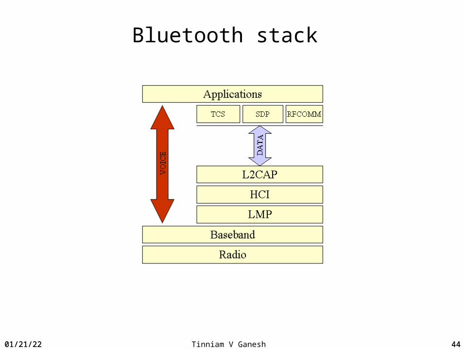
Bluetooth stack
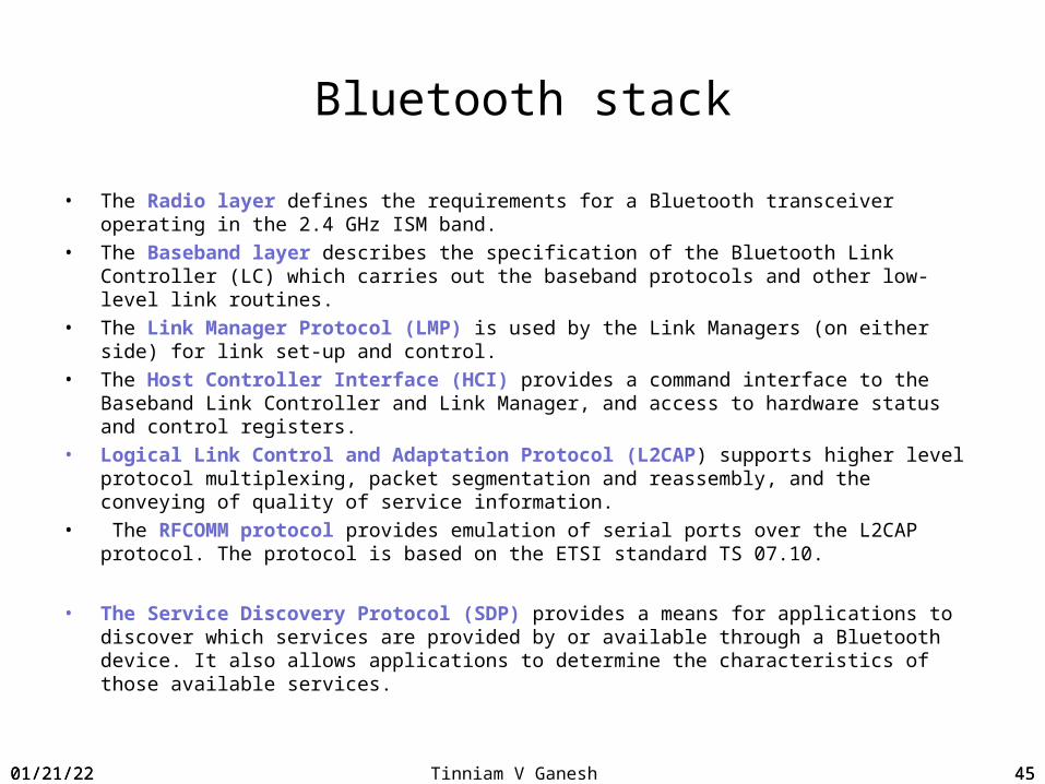
• The Radio layer defines the requirements for a Bluetooth transceiver operating in the 2.4 GHz ISM band.
• The Baseband layer describes the specification of the Bluetooth Link Controller (LC) which carries out the baseband protocols and other low-level link routines.
• The Link Manager Protocol (LMP) is used by the Link Managers (on either side) for link set-up and control.
• The Host Controller Interface (HCI) provides a command interface to the Baseband Link Controller and Link Manager, and access to hardware status and control registers.
• Logical Link Control and Adaptation Protocol (L2CAP) supports higher level protocol multiplexing, packet segmentation and reassembly, and the conveying of quality of service information.
• The RFCOMM protocol provides emulation of serial ports over the L2CAP protocol. The protocol is based on the ETSI standard TS 07.10.
• The Service Discovery Protocol (SDP) provides a means for applications to discover which services are provided by or available through a Bluetooth device. It also allows applications to determine the characteristics of those available services.
04/18/23 45
04/18/23 Tinniam V Ganesh 4604/18/23 46
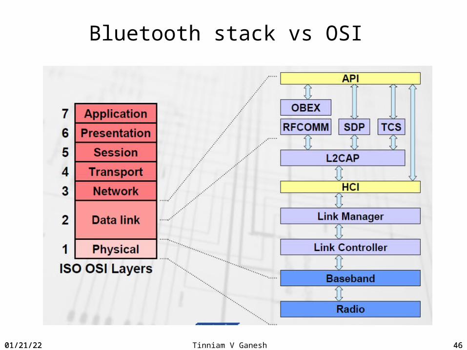
Bluetooth stack vs OSI

04/18/23 Tinniam V Ganesh 47
Bluetooth Features
04/18/23 47

04/18/23 Tinniam V Ganesh 4804/18/23 48
Blue tooth target devices
04/18/23 Tinniam V Ganesh 4904/18/23 49
04/18/23 Tinniam V Ganesh 50
Why WiFi ?
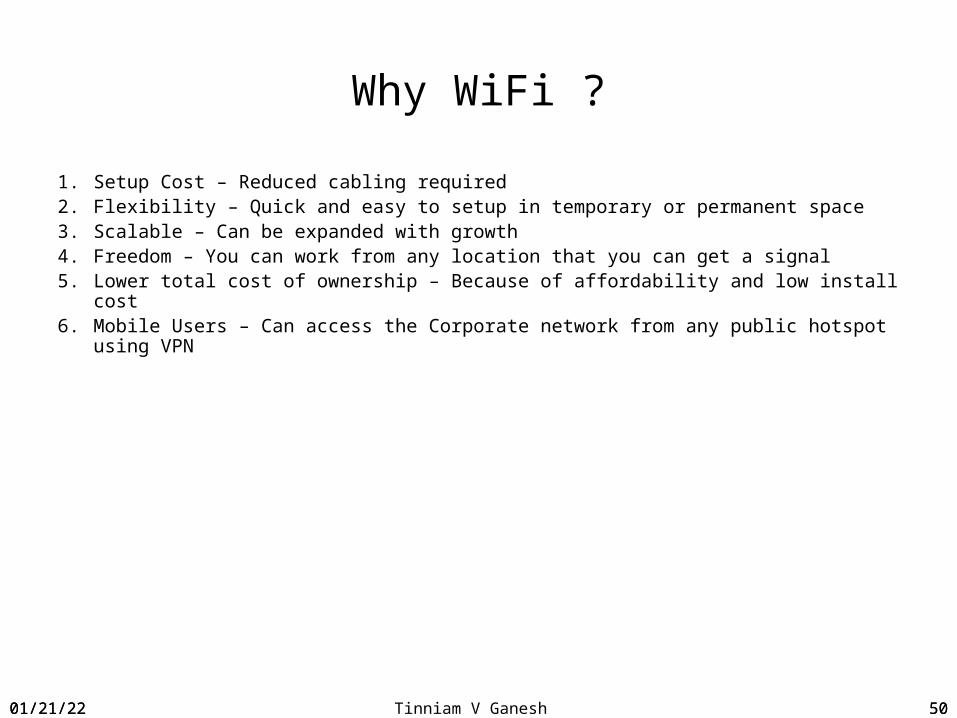
1. Setup Cost – Reduced cabling required2. Flexibility – Quick and easy to setup in temporary or permanent space3. Scalable – Can be expanded with growth4. Freedom – You can work from any location that you can get a signal5. Lower total cost of ownership – Because of affordability and low install cost6. Mobile Users – Can access the Corporate network from any public hotspot using VPN
04/18/23 50
04/18/23 Tinniam V Ganesh 51
802.11b
• Been around the longest, well-supported, stable, and cost effective, but runs in the 2.4 GHz range that makes it prone to interference from other devices (microwave ovens, cordless phones, etc) and also has security disadvantages
• Has 11 channels, with 3 non-overlapping, and supports• rates from 1 to 11 Mbps, but realistically about 4-5 Mbps• Uses direct-sequence spread-spectrum technology
04/18/23 51
04/18/23 Tinniam V Ganesh 52
802.11g
• Extension of 802.11b, with the same disadvantages (security and interference)
• Has a shorter range than 802.11b• Is backwards compatible with 802.11b so it allows or a smooth transition
from 11b to 11g• Flexible because multiple channels can be combined for faster throughput,
but limited to one access point• Runs at 54 Mbps, but realistically about 20-25 Mbps and about 14 Mbps
when b associated• Uses frequency division multiplexing technology
04/18/23 52
04/18/23 Tinniam V Ganesh 53
802.11a
Completely different from 11b and 11g.
1. Flexible because multiple channels can be combined for faster throughput and more access points can be collocated
2. Shorter range than 11b and 11g3. Runs in the 5 GHz range, so less interference from other devices4. Has 12 channels, 8 non-overlapping, and supports rates from 6 to 54 Mbps, but
realistically about 27 Mbps max5. Uses frequency division multiplexing technology
04/18/23 53
04/18/23 Tinniam V Ganesh 54
Security in WiFi
Data Security/Encryption• Third Party solution - Fortress• Wi-Fi Protected Access (WPA)• Wired Equivalent Privacy (WEP)-Shared key
Access WPA/WEP MAC Authentication – MAC address control
Attack – Denial of Service• Client Protection• Antivirus/Firewall
04/18/23 54
04/18/23 Tinniam V Ganesh 5504/18/23 55

04/18/23 Tinniam V Ganesh 56
Questions ?
04/18/23 56
04/18/23 Tinniam V Ganesh 57
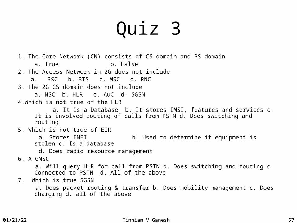
Quiz 31. The Core Network (CN) consists of CS domain and PS domain
a. True b. False2. The Access Network in 2G does not include
a. BSC b. BTS c. MSC d. RNC3. The 2G CS domain does not include
a. MSC b. HLR c. AuC d. SGSN4.Which is not true of the HLR a. It is a Database b. It stores IMSI, features and services c. It is involved routing of
calls from PSTN d. Does switching and routing5. Which is not true of EIR a. Stores IMEI b. Used to determine if equipment is stolen c. Is a database d. Does radio resource management6. A GMSC a. Will query HLR for call from PSTN b. Does switching and routing c. Connected to
PSTN d. All of the above7. Which is true SGSN a. Does packet routing & transfer b. Does mobility management c. Does charging d.
all of the above
04/18/23 57
04/18/23 Tinniam V Ganesh 58
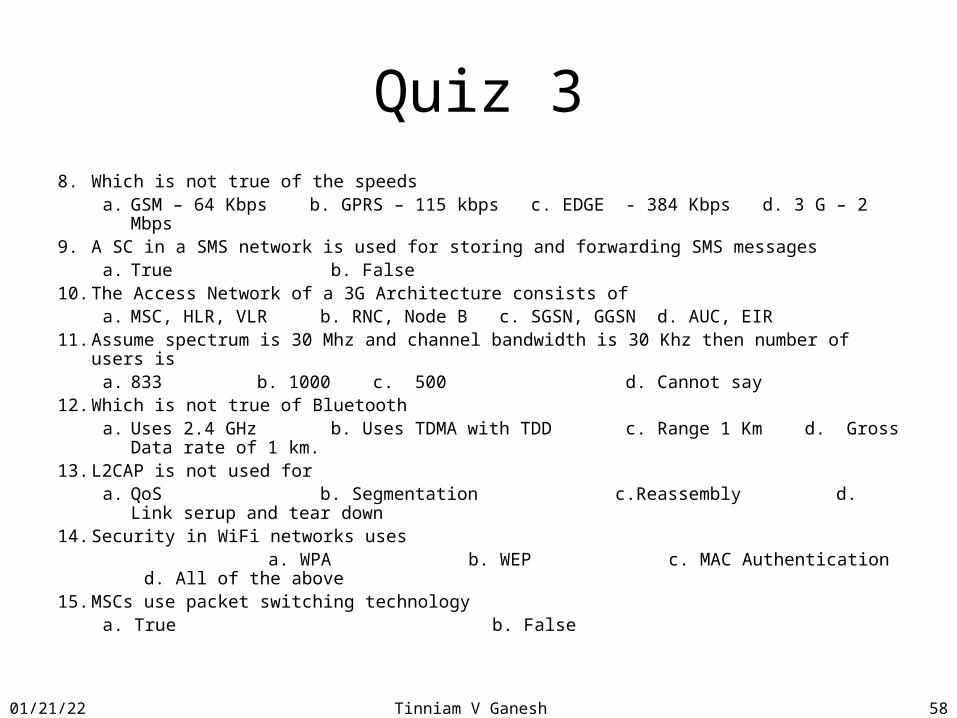
Quiz 38. Which is not true of the speeds
a. GSM – 64 Kbps b. GPRS – 115 kbps c. EDGE - 384 Kbps d. 3 G – 2 Mbps9. A SC in a SMS network is used for storing and forwarding SMS messages
a. True b. False10. The Access Network of a 3G Architecture consists of
a. MSC, HLR, VLR b. RNC, Node B c. SGSN, GGSN d. AUC, EIR11. Assume spectrum is 30 Mhz and channel bandwidth is 30 Khz then number of users is
a. 833 b. 1000 c. 500 d. Cannot say12. Which is not true of Bluetooth
a. Uses 2.4 GHz b. Uses TDMA with TDD c. Range 1 Km d. Gross Data rate of 1 km.
13. L2CAP is not used fora. QoS b. Segmentation c.Reassembly d. Link serup and tear
down14. Security in WiFi networks uses a. WPA b. WEP c. MAC Authentication d. All of the above15. MSCs use packet switching technology
a. True b. False

04/18/23 Tinniam V Ganesh 5904/18/23 59
Call flows and Advanced wireless concepts

04/18/23 Tinniam V Ganesh 60
Agenda – Session 4Call flows and Advanced wireless concepts
• GSM Air interface
• GSM air interface channels
• Location Updating Sequence Flows
• Mobile origination to PSTN
• PSTN origination to Mobile
• GPRS call flow
• SMS call Flow
• Recap
• Inter BSC Handoff scenario
• UMTS
• Softswitch
• IMS Architecture
• 3.5 G
• Mobile data explosion
• The evolution of LTE
• Recap
• Quiz 4
04/18/23 60

04/18/23 Tinniam V Ganesh 61
Basic Network Architecture
MSCHLR
BSCBTS
BTS
BTS
04/18/23 61
04/18/23 Tinniam V Ganesh 62
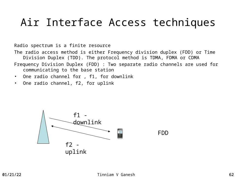
Air Interface Access techniques
Radio spectrum is a finite resourceThe radio access method is either Frequency division duplex (FDD) or Time Division
Duplex (TDD). The protocol method is TDMA, FDMA or CDMAFrequency Division Duplex (FDD) : Two separate radio channels are used for
communicating to the base station• One radio channel for , f1, for downlink• One radio channel, f2, for uplink
f1 - downlink
f2 - uplink
FDD
04/18/23 62

04/18/23 Tinniam V Ganesh 63
TDD
• Time Division Duplex (TDD)• One radio channel for communicating to base station. Duplexing is done on
time
04/18/23 63
04/18/23 Tinniam V Ganesh 64
Mobile radio propagation effects
• Signal strength– Must be strong enough between base station and mobile unit to
maintain signal quality at the receiver– Must not be so strong as to create too much co-channel interference
with channels in another cell using the same frequency band• Fading
– Signal propagation effects may disrupt the signal and cause errors
04/18/23 64

04/18/23 Tinniam V Ganesh 65
GSM Architecture
The interface between the BTS and BSC is known as the A-bis interfaceMSC One or more BSCs are connected to MSC. The MSC is a switch the node that
controls call setup, call routing and many of the functions provided by the standard telecommunication switch
VLR is a database that contains subscriber related information for the duration that a subscriber is in the coverage area of an MSC. The MSC and VLR are in the same platform,
The interface between the BSC and MSC is known as A-interfaceThis is a SS7 based interface using the SCCP. Above this is the BSS Application Part
(BSSAP) which is the protocol for communicating between the BSC and the MSC.Since the MSC communicated with the BSC and the MS the BSSAP is divided into two
parts the BSSMAP (BSS Management Application Part) and the Direct Transfer Application Part (DTAP)
BSSMAP are messages to BSSDTAP messages are passed transparently thro the BSS to the NS`
04/18/23 65

04/18/23 Tinniam V Ganesh 66
GSM Protocol stack
04/18/23 66
04/18/23 Tinniam V Ganesh 67
GSM Architecture
HLR The Home Location register contains subscriber data such has the details the subscriber has subscribed to . Associated with the HLR ios the authentication center (AuC). This is the network element that contains the subscriber specific authentication data such as the secret key
For a given subscriber using a random number generated by the AuC and passed to the SIM via the HLR., MSC and ME.
The SIM performs the calculation using the Ki and the authentication algorithm.
If the result os the calculation by the SIM matches that in AuC then the subscriner has been authenticated
04/18/23 67

04/18/23 Tinniam V Ganesh 68
GMSC
When a call from a PSTN it arrives at a type of MSC known as the GMSC.The GMSC queries the HLR to determine the location of the subscriberThe response from the HLR indicates to the GMSC when the subscriber may be
foundThe call is forwarded by the GMSC to the MSC serving the subscriber
04/18/23 68

04/18/23 Tinniam V Ganesh 69
The GSM Air interface
GSM uses TDMA with Frequency Division duples (FDD) GSM has been deployed in 900 Mhz, 1800 Mhz, 1900 MhzIn GSM a given band is divided into 200 Khz carries or RF channels in both uplink and
downlink directionsFor eg. In standard 900 Mhz band the first uplink is 890.2 Mhz and the last uplink is 914.8
allowing a total of 124 carriers914.8 Mhz – 890.2 Mhz = 24.6 Mhz/200 Khz = 123+ 1 carriers or channelsEach RF carrier is divided into 8 time slots . The 8 time slots are used to carry user traffic and also control traffic
04/18/23 69

04/18/23 Tinniam V Ganesh 70
Types of Air Interface channels
There are 3 types of channels1. Broadcast channels 2. Control channels3. Traffic channels
Broadcast ChannelsFrequency correction channel (FCCH) used for frequency correction of the MSSynchronization channel (SCH) – Broadcast by BTS and is used for mobile station for
frame synchronizationBroadcast Control Channel (BCCH) – Broadcast general information
Common Control Channel (CCCH) Paging channel – used for paging of the mobilesRandom Access Channel (RACH) – Only used in uplink. It is used to allocate to MS a Stand
alone dedicated Control Channel (SDCCH) or directly to a Traffic Channel (TCH)Access Grant Channel (AGCH) – used in the downlink in responswe to a access request
received on the RACH
04/18/23 70

04/18/23 Tinniam V Ganesh 71
Air interface channels• Notification Channel – used to notify MS• Standalone dedicated control channel (SDCCH) – Used towards MS when it
is not used for TCH. Used for SMS. Call establishment signaling prior to allocation of TCH
• Slow Associated Control Channel (SACCH) – Power Control messages from BTS to MS are sent on this channel. In the uplink the MS sends measurement reports to the BTS
• Fast Associated Control Channel (FACCH) – Used to transmit non voice information to and from the MS
04/18/23 71

04/18/23 Tinniam V Ganesh 72
Air interface channel structure
Certain time slots in a given RF carrier are allocated to control channel whereas the remaining are for traffic channels. For eg. Time slot 0 us for BCCH /CCCH . It may also carry 4 SDCCH
BCCH/CCCH/SDCCH TCH TCH TCH TCH TCH TCH TCH
04/18/23 72

04/18/23 Tinniam V Ganesh 73
How does the cellular network know the mobile’s position?
The cell phone keeps the cellular operator informed about your location.
04/18/23 73
04/18/23 Tinniam V Ganesh 74
Location Area
Location Area (LA)• A GSM network is divided into cells. A group of cells is considered a location
area. A mobile phone in motion keeps the network informed about changes in the location area. If the mobile moves from a cell in one location area to a cell in another location area, the mobile phone should perform a location area update to inform the network about the exact location of the mobile phone.
Home Location Register (HLR)• The HLR maintains a database for the mobile subscribers. At any point of
time, the HLR knows the address of the MSC VLR that control the current location area of the mobile. The HLR is informed about a location area update only if the location area change has resulted in a change of the MSC VLR.
Mobile Switching Center - Visitor Location Register (MSC VLR)• The MSC VLR is responsible to switching voice calls and it also keeps track
of the exact location area where the mobile user is present. Note that a typical MSC VLR will service several location areas.
04/18/23 74

04/18/23 Tinniam V Ganesh 75
Location Update
1. When the MS is switched on it must camp on a suitable cell. This involves scanning the air interface to select a cell with a suitably strong signal and decoding the informationbroadcast by the BTS on the BCCH
2. The MS makes a channel request on the RACH with a cause as Location Updating3. The BSS allocates an SDCCH for the MS to use. It instructs the MS to move to the
SDCCH by sending an immediate assignment message on the AGCH4. The MS then moves the SDCCH and send the location updating message. This
contains the location area identity and the mobile identity. The mobile identity is either the International Mobile Subscriber Identity (IMSI) or the Temporary Mobile Subscriber Identity (TMSI).
5. This is sent through the BSS to the NSC 6. On receipt of the IMSI the NSC.VLR attempt to authenticate the subscriber.7. If the MSC does not have authentication information then it request the HLR using
the MAP operation Send Authetication Info.8. The HLR AuC sends the MAP Return Result with up to five authentication vectors
04/18/23 75
04/18/23 Tinniam V Ganesh 76
Location Update
Known as triplets. Each triplet contains a random number (RAND) and a signed response (SRES)
9. The MSC sends an Authentication request to the MS. This contains the RAND.10. The MS performs the same calculations as were performed by the HLR/AuC and
send the Authentication response containing the SRES parameter.11. The MSC/VLR check rto make sure that the SRES from the MS matches the SRES
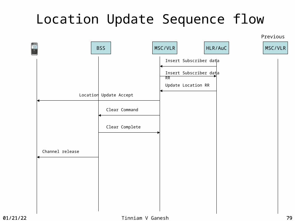
from HLR/AuC12. If a match is made then the MS is authenticated13. At this point the MSC/VLR use te MAP Operation Update Location to inform the HLR
of the subscriber location.14. The HLR immediately sends a Cancel Location message to the VLR to remove anty
previous location15. VLR deletes any previous data16. HLR uses a MAP operation to Insert Subscriber data to VLR17. VLR acknowledges receipt of information18. HLR sends a return result of the MAP Update Location
04/18/23 76

04/18/23 Tinniam V Ganesh 77
Location Update
19. On receipt of the return result the MSC sends a DTAP message Location Updating Accept to the MS
04/18/23 77

04/18/23 Tinniam V Ganesh 78
Location Update Sequence flow
Channel Request
Immediate Channel Assignment
Location Updating Request
Location Updating Request
Send Authentication Info
Send Authentication Info RR
Authentication Request
BSS MSC/VLR HLR/AuC MSC/VLR
Previous
Authentication Response
Update Location
Cancel Location
Cancel Location RR
04/18/23 78
04/18/23 Tinniam V Ganesh 79
Location Update Sequence flow
Insert Subscriber data RR
BSS MSC/VLR HLR/AuC MSC/VLR
Previous
Insert Subscriber data
Update Location RR
Location Update Accept
Clear Command
Clear Complete
Channel release
04/18/23 79
04/18/23 Tinniam V Ganesh 80
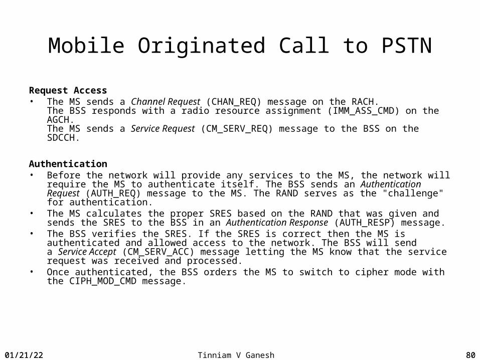
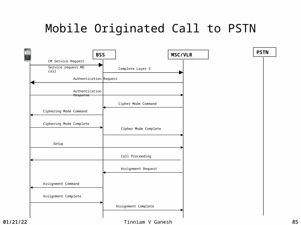
Mobile Originated Call to PSTN
Request Access• The MS sends a Channel Request (CHAN_REQ) message on the RACH.
The BSS responds with a radio resource assignment (IMM_ASS_CMD) on the AGCH. The MS sends a Service Request (CM_SERV_REQ) message to the BSS on the SDCCH.
Authentication• Before the network will provide any services to the MS, the network will require the
MS to authenticate itself. The BSS sends an Authentication Request (AUTH_REQ) message to the MS. The RAND serves as the "challenge" for authentication.
• The MS calculates the proper SRES based on the RAND that was given and sends the SRES to the BSS in an Authentication Response (AUTH_RESP) message.
• The BSS verifies the SRES. If the SRES is correct then the MS is authenticated and allowed access to the network. The BSS will send a Service Accept (CM_SERV_ACC) message letting the MS know that the service request was received and processed.
• Once authenticated, the BSS orders the MS to switch to cipher mode with the CIPH_MOD_CMD message.
04/18/23 80
04/18/23 Tinniam V Ganesh 81
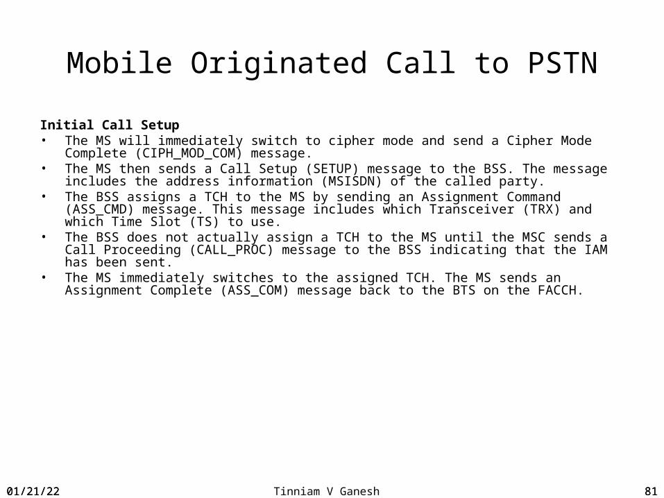
Mobile Originated Call to PSTN
Initial Call Setup• The MS will immediately switch to cipher mode and send a Cipher Mode Complete
(CIPH_MOD_COM) message.• The MS then sends a Call Setup (SETUP) message to the BSS. The message includes
the address information (MSISDN) of the called party.• The BSS assigns a TCH to the MS by sending an Assignment Command (ASS_CMD)
message. This message includes which Transceiver (TRX) and which Time Slot (TS) to use.
• The BSS does not actually assign a TCH to the MS until the MSC sends a Call Proceeding (CALL_PROC) message to the BSS indicating that the IAM has been sent.
• The MS immediately switches to the assigned TCH. The MS sends an Assignment Complete (ASS_COM) message back to the BTS on the FACCH.
04/18/23 81

04/18/23 Tinniam V Ganesh 82
Mobile Originated Call to PSTN
Call Setup• The MSC sends an Initial Address Message (IAM) to the GMSC. The IAM contains the
MSISDN of the called party as the MS dialed it.• The MSC will also send a Call Proceeding (CALL_PROC) message down to the BSS and
this is when the BSS would assign a TCH to the MS, as described in step 10 above.• Based on the dialed number, the GMSC decides where to route the IAM within the
PSTN.• The PSTN will continue to route the IAM until it reaches the correct Switching Center
and the call routing is complete. The PSTN will then establish the call circuit and send an Address Complete Message (ACM) back to the GMSC.
• The GMSC then forwards the ACM back to the responsible MSC indicating that the call circuit has been established
04/18/23 82

04/18/23 Tinniam V Ganesh 83
Mobile Originated Call to PSTN
Call Establishment• Once the MSC receives the ACM, it sends an ALERT message to the MS
indicating that the call is going through. The BSS sends the ALERT message on the FACCH. Once the MS receives the ALERT, it will generate the ringing sound in the earpiece. The BSS sends an alerting message the subscriber will hear the line ringing.
• Once the called party answers the phone, the PSTN will send an Answer message to the MSC. The MSC forwards this to the MS in a Connection (CON) message.
• Once the MS receives the CON message, it switches over to voice and begins the call. All voice traffic occurs on the assigned TCH.
04/18/23 83
04/18/23 Tinniam V Ganesh 84
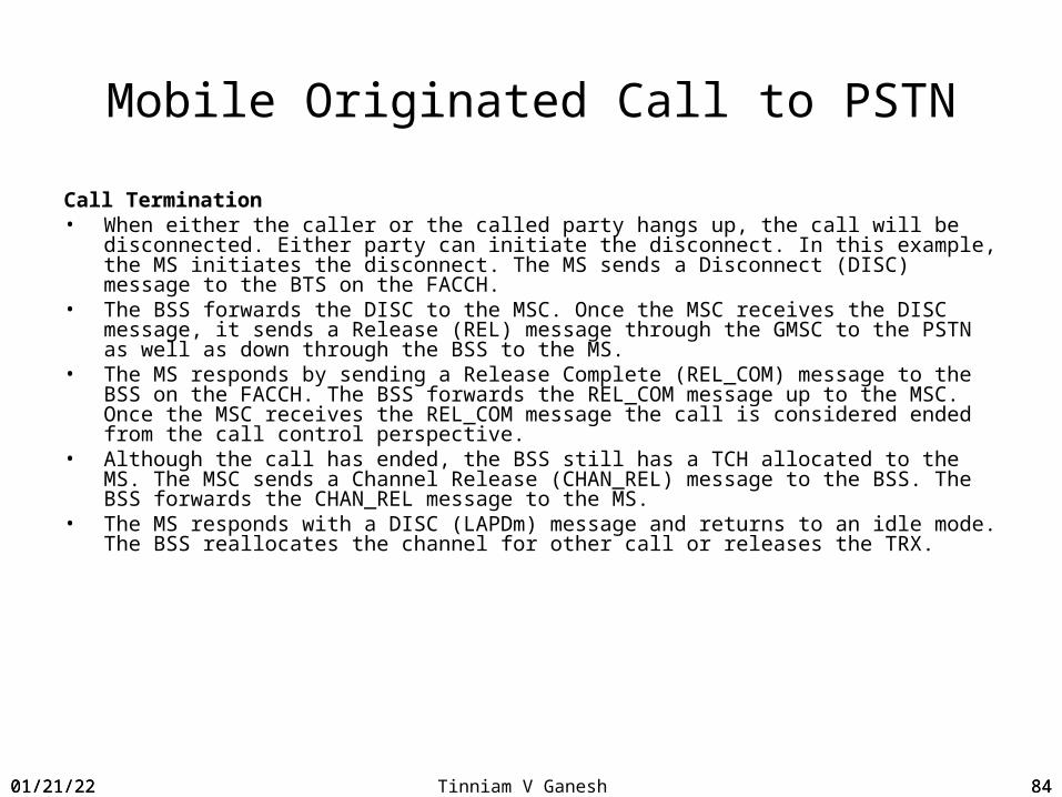
Mobile Originated Call to PSTN
Call Termination• When either the caller or the called party hangs up, the call will be disconnected.
Either party can initiate the disconnect. In this example, the MS initiates the disconnect. The MS sends a Disconnect (DISC) message to the BTS on the FACCH.
• The BSS forwards the DISC to the MSC. Once the MSC receives the DISC message, it sends a Release (REL) message through the GMSC to the PSTN as well as down through the BSS to the MS.
• The MS responds by sending a Release Complete (REL_COM) message to the BSS on the FACCH. The BSS forwards the REL_COM message up to the MSC. Once the MSC receives the REL_COM message the call is considered ended from the call control perspective.
• Although the call has ended, the BSS still has a TCH allocated to the MS. The MSC sends a Channel Release (CHAN_REL) message to the BSS. The BSS forwards the CHAN_REL message to the MS.
• The MS responds with a DISC (LAPDm) message and returns to an idle mode. The BSS reallocates the channel for other call or releases the TRX.
04/18/23 84
04/18/23 Tinniam V Ganesh 85
Mobile Originated Call to PSTN
CM Service Request
Service request MO call
BSS MSC/VLR PSTN
Complete Layer 3
Authentication Request
Authentication Response
Cipher Mode Command
Ciphering Mode Command
Ciphering Mode Complete
Cipher Mode Complete
Call Proceeding
Setup
Assignment Request
Assignment Command
Assignment Complete
Assignment Complete
04/18/23 85

04/18/23 Tinniam V Ganesh 86
Mobile Originated Call to PSTN
IAM
BSS MSC/VLR PSTN
ACM
Alerting
ANM
ANM
Connect Acknowledge
04/18/23 86

04/18/23 Tinniam V Ganesh 87
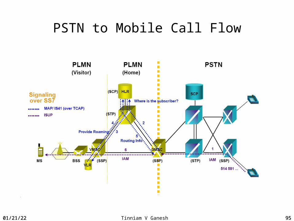
PSTN to Mobile call flow
Mobile Terminated Call• Route Establishment to find the MSC/VLR• The calling party dials the MSISDN for the mobile subscriber. The PSTN identifies the
network (PLMN) that the dialed MSISDN belongs to and will locate a GMSC for that network. The PSTN sends an Initial Address message to the GMSC.
• The GMSC forwards the MSISDN to the HLR and requests routing information for it. The HLR looks up the MSISDN and determines the IMSI and the SS7 address for the MSC/VLR that is servicing the MS.
• The HLR then contacts the servicing MSC/VLR and asks it to assign a Mobile Station Routing Number (MSRN) to the call.
• The MSC/VLR allocates the MSRN and forwards it to the HLR.Note: It is important to remember that the MSC/VLR assigns a MSRN to the call not to the MS itself.
• The HLR forwards the MSRN as well as routing information for the servicing MSC/VLR to the GMSC.
• The GMSC sends an Initial Addressing message to the servicing MSC/VLR and uses the MSRN to route the call to the MSC/VLR. Once the servicing MSC/VLR receives the call, the MSRN can be released and may be made available for reassignment.
04/18/23 87

04/18/23 Tinniam V Ganesh 88
PSTN to Mobile call flow
Paging the Mobile Station• The MSC/VLR then orders all of its BSCs and BTSs to page the MS. Since the MSC/VLR
does not know exactly which BSC and BTS the MS is monitoring, the page will be sent out across the entire Location Area.
Initial Setup• The MS receives the Page Request (PAG_REQ) on the PCH. The MS recognizes that
the page is intended for it, based on a TMSI or an IMSI.• The MS sends a Channel Request (CHAN_REQ) message on the RACH.• The BSS responds on the AGCH by sending an Immediate Assignment (IMM ASS)
message which assigns an SDCCH to the MS. At this point, the network does not know that the MS is the one that it is paging, it only knows that this MS wants access to the network
• The MS immediately switches to the assigned SDCCH and sends a Paging Response (PAG_RES) message on the SDCCH. This lets the network know that the MS is responding to its page.
04/18/23 88
04/18/23 Tinniam V Ganesh 89
PSTN to Mobile call flow
Authentication• Before the network will provide any services to the MS, the network will
require the MS to authenticate itself. The BSS sends an Authentication Request (AUTH_REQ) message to the MS. The RAND serves as the "challenge" for authentication.
• The MS calculates the proper SRES based on the RAND that was given and sends the SRES to the BSS in anAuthentication Response (AUTH_RESP) message.
• The BSS verifies the SRES. If the SRES is correct then the MS is authenticated and allowed access to the network.
• Once the MSC/VLR has authenticated the MS, it will order the BSS and MS to switch to cipher mode using the CIPH_MOD_CMD message. Once the MS in encryption mode, the VLR will normally assign a new TMSI to the MS.
04/18/23 89
04/18/23 Tinniam V Ganesh 90
PSTN to Mobile call flow
Establishing a Channel• Once the MS is authenticated and in encryption mode, The MSC sends a Setup
Message to the BSS, the BSS forwards the SETUP message to the MS on the assigned SDCCH.the assigned SDCCH. The SETUP message may include the Calling Line Identification Presentation (CLIP), which is essentially caller ID.
• The MS responds by sending a Call Confirmed (CALL_CON) message; which indicates that the MS is able to establish the requested connection. The BSS relays the message up to the MSC.
Call Setup• The BSS then sends an Assignment Command (ASS_CMD) message to the MS on the
assigned SDCCH. The ASS_CMD message assigns a Traffic Channel (TCH) to the MS.• The MS immediately switches to the TCH and responds with an Assignment
Complete (ASS_COM) message on the FACCH. The MS begins ringing once it has established the TCH. Remember that all signaling that occurs on the traffic channel actually occurs on a FACCH, which is a time slot that is stolen from the TCH and used for signaling.
The MS sends an ALERT message to the MSC on the FACCH. The BSS forwards the ALERT message through the PSTN to the calling party and the caller hears the line ringing.
04/18/23 90
04/18/23 Tinniam V Ganesh 91
PSTN to Mobile call flow
Call Establishment• Once the user answers the call (by pressing the send button), the MS will send
a Connect CON message to the MSC. The Connect message is forwarded back to the caller's switch to activate the call.
• The MSC sends a Connect Acknowledge CON_ACK message to the MS and the call is established.
• Call Disconnect• Disconnect happens the same way as for any other call. In this example, the calling
party initiates the disconnect.• When the calling party hangs up, the calling party's switch initiates a Release (REL)
message. The message is forwarded to the serving MSC, which is then forwarded to the BSS.
• The BSS will send a Disconnect (DISC) message to the MS on the FACCH.
04/18/23 91

04/18/23 Tinniam V Ganesh 92
PSTN to Mobile call flow
• The MS confirms release of the call by sending a Release (REL) message on the FACCH, which is forwarded to the MSC.
• The MSC sends e Release Complete (REL_COM) message through the BSS to the MS. As far as call control (CC) is concerned, the connection has been terminated.
• The MS still has a TCH assigned to it, so the BSS sends a Channel Release (CHAN_REL) message to the MS. This releases the radio resource on the Air Interface.
• The MS responds be sending a final Disconnect message and returns to idle.
04/18/23 92

04/18/23 Tinniam V Ganesh 93
PSTN to Mobile call flow
BSS MSC/VLR HLR GMSC PSTN
IAM
Send Routing Info (SRI)
Provide Routing Number (PRN)
IAM (MSRN)
Paging
Channel Request
Paging RequestPaging Request
Immediate Assignment
Paging Response
Paging Response
Cipher mode command
Ciphering mode command
Ciphering mode response
04/18/23 93

04/18/23 Tinniam V Ganesh 94
PSTN to Mobile call flow
BSS MSC/VLR HLR GMSC PSTN
Cipher mode complete
Setup
Call confirmed
Assignment request
Assignment command
Assignment complete
Alerting
ACM
Connect
ACM
ANM
ANM
Connect Acknowledge
04/18/23 94
04/18/23 Tinniam V Ganesh 95
PSTN to Mobile Call Flow
04/18/23 95

04/18/23 Tinniam V Ganesh 96
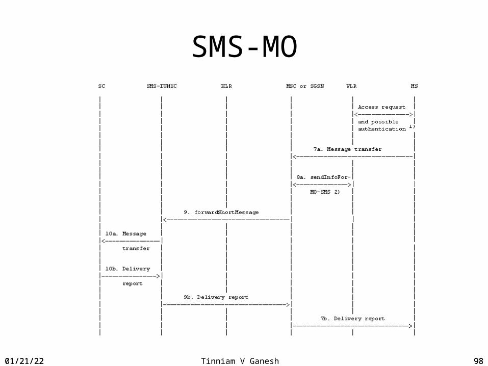
SMS-MO
1. The mobile station transfers the short message to the MSC.
2. The MSC queries the VLR to verify that the message transfer does not violate the supplementary services invoked or the restrictions imposed on the subscriber.
3. The MSC sends the short message to the SMSC using the forwardShortMessage operation.
4. The SMSC delivers the short message to the SMC.
5. The SMSC acknowledges the successful outcome of the forwardShortMessage operation to the MSC.
6. The MSC returns the outcome of the short message operation to the mobile station.
04/18/23 96

04/18/23 Tinniam V Ganesh 97
SMS-MO
SCSMS-IWMSC
MSC MSx
VLR
SGSN
04/18/23 97
04/18/23 Tinniam V Ganesh 98
SMS-MO
04/18/23 98

04/18/23 Tinniam V Ganesh 99
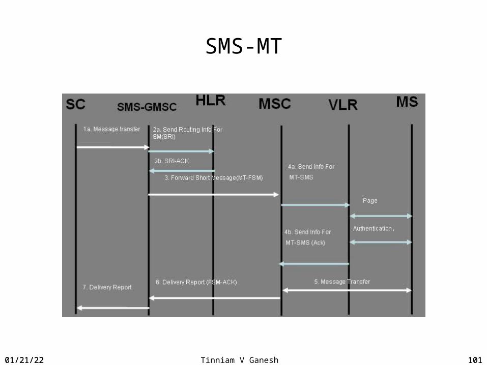
SMS-MT
1.The Short message is transferred from SC to SMS-GMSC2.SMS-GMSC queries the HLR(SRI) and receives the routing information for the mobile
subscriber (SRI-ACK).3. The SMS-GMSC sends the short message to the MSC using the forwardShortMessage
operation(FSM).4. The MSC retrieves the subscriber information from the VLR. This operation may include
an authentication procedure.5. The MSC transfers the short message to the mobile station.`6. The MSC returns the outcome of the forwardShortMessage operation to the SMS-
GMSC(FSM-ACK).7. If requested by the SMC, the SMSC returns a status report indicating delivery of the
short message.
04/18/23 99

04/18/23 Tinniam V Ganesh 100
SCSMSC-GMSC
MSCMS
x
HLR VLR
SGSN
SMS-MT
04/18/23 100
04/18/23 Tinniam V Ganesh 101
SMS-MT
04/18/23 101

04/18/23 Tinniam V Ganesh 102
Handover
A handover (aka handoff) is the process by which a call in progress is transferred from one radio channel in the same cell or different cell.
A handover can occur Within a cellBetween cells of the same BTSBetween cells of diffferent BTS of same BSCBetween cells of different BSC Between cells of different MSCs
04/18/23 102

04/18/23 Tinniam V Ganesh 103
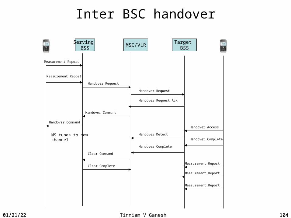
Inter BSC handover
Inter BSC handover• The BSC must involve the MSC• One the serving BSC determines that a handover should take place it sends a
message handover required too the NSC• The message contains information about the desired target cell and the the current
cell• The MSC analyzes the information and identifies the target BSC associated with the
target cell• It then sends a Handover Request to rthe target BSC
04/18/23 103
04/18/23 Tinniam V Ganesh 104
Inter BSC handover
Serving BSS
MSC/VLRTarget
BSS
Measurement Report
Measurement Report
Handover Request
Handover Request
Handover Request Ack
Handover Command
Handover Command
MS tunes to new channel
Handover Access
Handover Detect
Handover Complete
Handover Complete
Clear Command
Clear CompleteMeasurement Report
Measurement Report
Measurement Report
04/18/23 104

04/18/23 Tinniam V Ganesh 105
Hand-off scenario
04/18/23 105

04/18/23 Tinniam V Ganesh 106
Handoff/handover
• Handoff (also known as handover) is the ability of the subscriber to maintain a call while moving within a network
• Handoff is used in AMPS, IS-136 and IS-95. In GSM it is called handover• Handover means that subscriber is transitioned from one radio channel
and/or time slot) to another.• Depending on the two cells in question the handover can be between two
sectors on the same station between two BSCs between 2 MSCs or even between networks
Base station BBase station A
Base station BBase station A
04/18/23 106

04/18/23 Tinniam V Ganesh 107
GPRS call flow
Attach• The terminal initiates a attach process• The SGSN authenticates the GPRS mobile by sending a RAND value (a random
value).• The SIM applies secret GSM algorithms on the RAND and the secret key Ki to
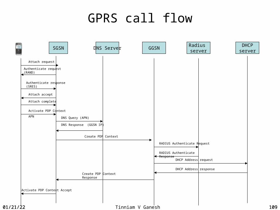
obtain the session key Kc and SRES. • The computed SRES value is passed to the SGSN.• SGSN authenticates the response• SGSN accepts the attach requestActivate PDP context7. The terminal does a PDP Activate PDP context8. SGSN does a DNS Query to the DNS server to find the address of the GGSN (Global
GPRS Support Node)9. The DNS server sends the IP Address of the GGSN10. The SGSN sends a Create PDP Activate context to the GGSN11. The GGSN does a RADIUS authenticate to RADIUS server12. The RADIUS does a authenticate response
04/18/23 107
04/18/23 Tinniam V Ganesh 108
GPRS call flow
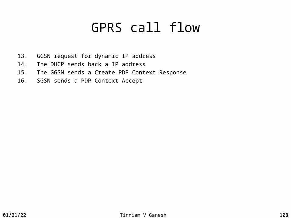
13. GGSN request for dynamic IP address14. The DHCP sends back a IP address15. The GGSN sends a Create PDP Context Response16. SGSN sends a PDP Context Accept
04/18/23 108
04/18/23 Tinniam V Ganesh 109
GPRS call flow
SGSN DNS Server GGSNRadius server
DHCPserver
Attach request
Authenticate response (SRES)
Authenticate request (RAND)
Attach complete
Create PDP Context
RADIUS Authenticate Request
Activate PDP Context Accept
Attach accept
Activate PDP Context
APN DNS Query (APN)
DNS Response (GGSN IP)
RADIUS Authenticate Response
DHCP Address request
DHCP Address response
Create PDP Context Response
04/18/23 109

04/18/23 Tinniam V Ganesh 11004/18/23 110

04/18/23 Tinniam V Ganesh 111
Universal Mobile Telecommunication Service (UMTS)
UMTS represents an evolution of GSM to support 3G capabilitiesThe air interface is known as UTRANUMTS uses Wideband CDMA (WCDMA)The air interface consists of1. Node B2. RNCCore Network1. MSC Server2. Media Gateway3. HLR4. VLR5. GMSC
04/18/23 111

04/18/23 Tinniam V Ganesh 112
UTRAN
UMTS Terrestrial Radio Access Network (UTRAN)The UTRAN consists of the Radio Network Controller (RNC) and Node B which is the base
stationThe RNC is analogous to the GSM BSC The Base station is equivalent to the Node B
04/18/23 112
04/18/23 Tinniam V Ganesh 113
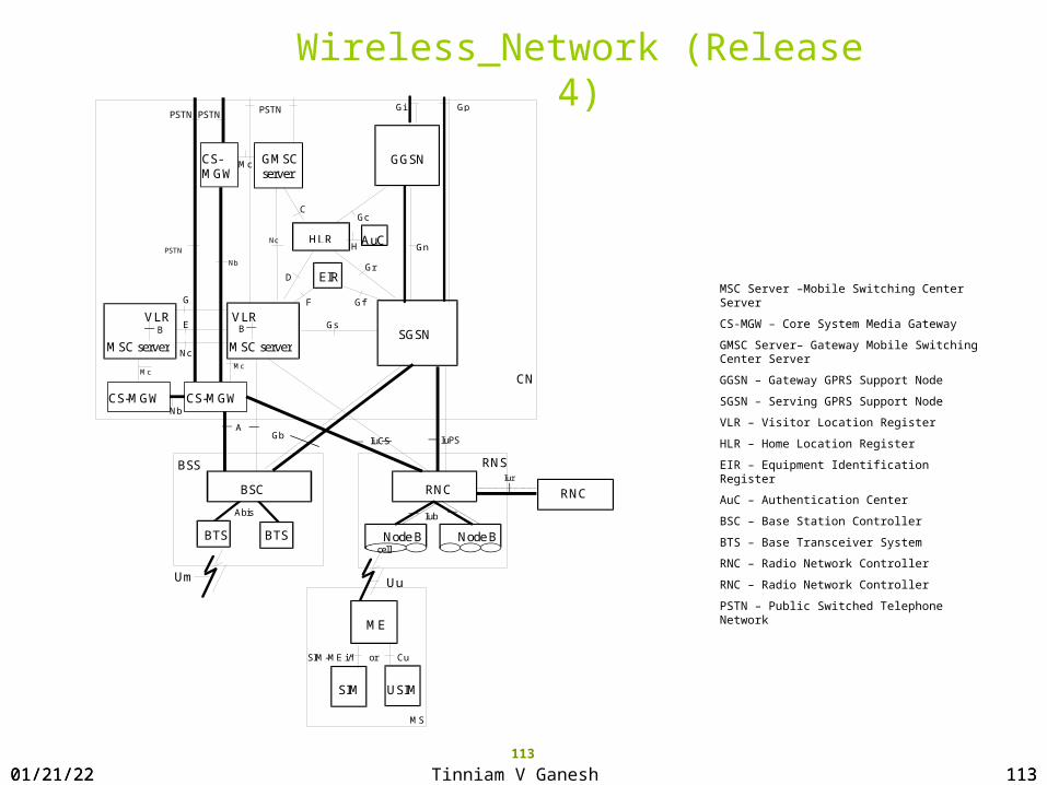
MSC Server –Mobile Switching Center Server
CS-MGW – Core System Media Gateway
GMSC Server– Gateway Mobile Switching Center Server
GGSN – Gateway GPRS Support Node
SGSN – Serving GPRS Support Node
VLR – Visitor Location Register
HLR – Home Location Register
EIR – Equipment Identification Register
AuC – Authentication Center
BSC – Base Station Controller
BTS – Base Transceiver System
RNC – Radio Network Controller
RNC – Radio Network Controller
PSTN – Public Switched Telephone Network
Wireless Network (Release 4)
113
BSS
BSC
RNS
RNC
CN
Node B Node B
IuPS
Iur
Iub
USIM
ME
MS
Cu
Uu
MSC server SGSN
Gs
GGSN GMSC server
Gn HLR
Gr
Gc C
D
Nc
H
EIR
F Gf
Gi PSTN
IuCS
VLR B
Gp
VLR
G
BTS BTS
Um
RNC
Abis
SIM
SIM-ME i/f or
MSC server
B
PSTN
cell
CS-MGW CS-MGW
CS-MGW
AuC
Nb
Mc Mc
Nb
PSTN PSTN
Nc
Mc
A Gb
E
04/18/23 113

04/18/23 Tinniam V Ganesh 114
3G Rel 4 Architecture - Softswicth
04/18/23 114

04/18/23 Tinniam V Ganesh 115
UMTS Network Architecture
SoftswitchHLR
RNC
Node B
Node B
Node B
04/18/23 115
04/18/23 Tinniam V Ganesh 116
Softswitch
• Softswitch denotes a component in a new architecture designed for migrating from a voice centric world to a data centric world.
• Separates signaling from the bearer traffic allowing for greater flexibility and efficiency
• Represents a move from the monolithic traditional circuit switches to a more distributed, open architecture and provides for greater degree of flexibility
04/18/23 116

04/18/23 Tinniam V Ganesh 117
TDM
TDM
Time Slot
Inter-change
Signaling&
Control
Line Interfaces
Line Interfaces
Softswitch vs Legacy Switch
Application Servers
SS7 SS7
TDM or IP
TDM or IP
Media Gateway
Media Gateway
Packet
Signaling&
Control
– Monolithic(Control + Bearer Integrated)
– Proprietary Interfaces– Inefficient Resource Utilization– Limited Scalability– Higher Operating Costs– Long Feature Development Intervals
– Disaggregated(Control separated from Bearer)
– Open Interfaces– Most Efficient Resource Utilization– High Scalability– Lower Capital / Operating Costs– Rapid Feature Development / 3rd Party
04/18/23 117

04/18/23 Tinniam V Ganesh 118
IMS Architecture
IMS is a framework of network nodes that use SIP signaling and an all IP core. Access agnostic. The network can be accessed by Fixed lines, mobiles, PDA etc Promises rich services like voice, data, video conferencing, real time gaming etc Uses the GPRS network Uses DIAMETER for AAA and database access Allows for Fixed Mobile Convergence
04/18/23 118

04/18/23 Tinniam V Ganesh 11904/18/23 119
IMS Network
04/18/23 Tinniam V Ganesh 120
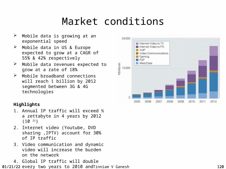
Market conditions Mobile data is growing at an
exponential speed Mobile data in US & Europe expected
to grow at a CAGR of 55% & 42% respectively
Mobile data revenues expected to grow at a rate of 18%
Mobile broadband connections will reach 1 billion by 2012 segmented between 3G & 4G technologies
Highlights1. Annual IP traffic will exceed ½ a
zettabyte in 4 years by 2012 (10 21)2. Internet video (Youtube, DVD
sharing ,IPTV) account for 30% of IP traffic
3. Video communication and dynamic video will increase the burden on the network
4. Global IP traffic will double every two years to 2010 and beyond
04/18/23 120

04/18/23 Tinniam V Ganesh 121
The explosion of mobile data
In the last 2 years • 1 billion new mobile subscriptions added• 2 billion wireless devices sold
Device range from Mobile phones, Smartphones, Netbooks, PDAs, Wireless dongles and Tablets
• Currently there are 3.5 billion subscribers worldwide• 3G accounts for 350 million with 30 million added every quarter• LTE forecast to reach 32.6 million by 2013
04/18/23 121

04/18/23 Tinniam V Ganesh 122
The rise and rise of data
04/18/23 122

04/18/23 Tinniam V Ganesh 123
Growth in data traffic
04/18/23 123

04/18/23 Tinniam V Ganesh 124
3.5 GHigh Speed Downlink Packet Data Access (HSDPA) Enhanced modulation scheme over WCDMA with throughput of 14.4 MbpsUses 16 QAM in addition QPSK
High Speed Uplink Packet Data Access (HSUPA)Enables uplink of 1.4 Mbps upto 5.76 Mbps
GSM GPRSWCDMARel 99
HSDPA Rel 5
HSUPA Rel 6
EDGE
04/18/23 124

04/18/23 Tinniam V Ganesh 125
Elements of the LTE System
LTE encompasses the evolution of • Radio access through E-UTRAN (eNodeB)• Non-radio aspects under the term System Architecture Evolution (SAE)
Entire system composed of LTE & SAE is called Evolved Packet System (EPS)
At a high level a LTE network is composed of 1. Access network comprised of E-UTRAN2. Core Network called Evolved Packet Core (EPC)
04/18/23 125

04/18/23 Tinniam V Ganesh 126
UE – User Equipment used to connect to the EPS (Evolved Packet System). This is an LTE capable UE
The LTE network is comprised of a) Access Network b) Core Network
Access network ENB (eNodeB) – The evolved RAN consists of single node, the eNodeB that interfaces with UE. The eNodeB hosts the PHY,MAC, RLC & RRC layers. It handles radio resource management & scheduling.
Core Network (Evolved Packet Core-EPC) MME (Mobility Management Entity) – Performs paging, chooses the SGW during UE attach
S-GW (Serving Gateway) – routes & and forwards user data packets
P-GW (Packet Gateway) – provides connectivity between the UE and the external packet networks.
LTE Network Elements
04/18/23 126

04/18/23 Tinniam V Ganesh 127
LTE Network Elements
04/18/23 127
04/18/23 Tinniam V Ganesh 128
LTE Technologies
LTE uses OFDM (Orthogonal Frequency Division Multiplexing) for lower latency and better spectral efficiency
Uses MIMO (Mulitple In Multiple Out) LTE uses several transmit & receive paths reducing interference with increase in spectral efficiency and throughput.
Flatter architecture – Fewer Network elements in the LTE Evolved Packet Core(EPC). This results in lower latency because of lesser number of hops as compared to 3G. Absence of RNC like Network Element(NE).
04/18/23 128

04/18/23 Tinniam V Ganesh 129
2.5G GPRS Network Elements
04/18/23 129
04/18/23 Tinniam V Ganesh 130
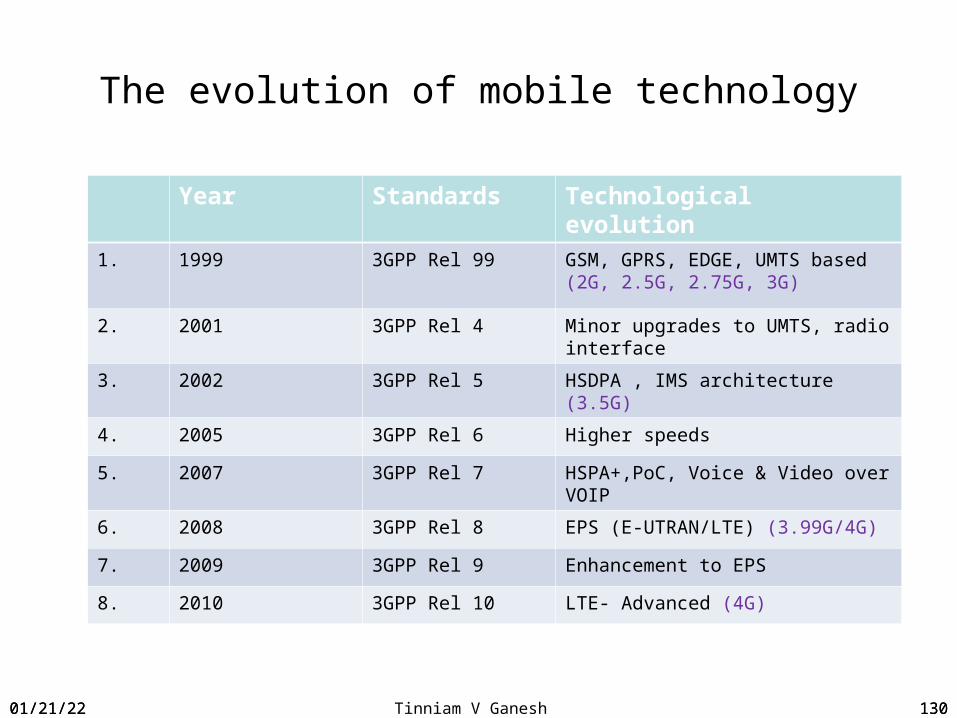
The evolution of mobile technology
Year Standards Technological evolution1. 1999 3GPP Rel 99 GSM, GPRS, EDGE, UMTS based
(2G, 2.5G, 2.75G, 3G)
2. 2001 3GPP Rel 4 Minor upgrades to UMTS, radio interface
3. 2002 3GPP Rel 5 HSDPA , IMS architecture (3.5G)
4. 2005 3GPP Rel 6 Higher speeds
5. 2007 3GPP Rel 7 HSPA+,PoC, Voice & Video over VOIP
6. 2008 3GPP Rel 8 EPS (E-UTRAN/LTE) (3.99G/4G)
7. 2009 3GPP Rel 9 Enhancement to EPS
8. 2010 3GPP Rel 10 LTE- Advanced (4G)
04/18/23 130

04/18/23 Tinniam V Ganesh 13104/18/23 131
04/18/23 Tinniam V Ganesh 132
Questions ?
04/18/23 132

04/18/23 Tinniam V Ganesh 133
Quiz 4
1. A call from a PSTN to wireless network comes first to the a. MSC b. GMSC c. HLR d. VLR
2. The GMSC determines where to route the call by a. Checking its VLR b. Querying the HLR c. It knows where the mobile is d.
none of the above3. GSM has been deployed in
a. 800 Mhz b. 1800 Mhz c. 1900 Mhz d. 2.4 Ghz4. Which is not an Air Interface channel a. Broadcast channel b. Control channel c. Traffic channel d.
All of the above5. SDCCH is used for a. SMS b. For call establishment signaling c. both a & b d. None of the abover6. How does a mobile inform its whereabouts a. It is stored in HLR b. By doing a Location Update c. HLR is informed of location
changes d. Both b & c7. While doing Location Update, authentication is done at AuC & Mobile a. True b. False8. For Authentication MSC sends the mobile a. RAND b. SRES c. Ki d. All of the above9. MS sends a channel request on a. RACH b. AGCH c. SDCCH d. TCH
04/18/23 133

04/18/23 Tinniam V Ganesh 134
Quiz 4
10. Which of the following is true in a PSTN to mobile call a. GMSC sends MSISDN to HLR b. HLR determines MSC/VLR from MSISDN c.
MSC/VLR sends a MSRN d. all of the above11. UMTS uses 1. TDMA with FDD 2. CDMA 3. WCDMA 4. FDMA with FDD12. Softswitch separates bearer from control a. True b. False13. Which is not true for softswitch a. Uses time slot interchange b. uses media gateway c. does packet switching d.
none of the above14. Which of the following is true for IMS a. Uses SIP signaling b. Uses an IP Core c. Uses DIAMETER d. all of the above15. LTE is made of the following a. BTS, BSC, MSC b. Node B, RNC, Softswitch c. Node B, RNC, SGSN,
GGSN d. eNodeB, MME, SGW, GGW
04/18/23 134
04/18/23 Tinniam V Ganesh 135
Good luck & thank You !!!
04/18/23 135
Tinniam V Ganesh
Read my blogs: http://gigadom.wordpress.com/
http://savvydom.wordpress.com/