Wireless Seminar .ppt - AZITE · Systems integration and wireless technology ... alarm status Time...
33
Transcript of Wireless Seminar .ppt - AZITE · Systems integration and wireless technology ... alarm status Time...

����������������
����������������
�� ������ ����
����������������������������

������������������
� Founded 1990� Located in Lancaster NY (near Buffalo)� Systems integration and wireless technology
development history.� Acquired assets and exclusive rights to Aria Wireless � Acquired assets and exclusive rights to Aria Wireless
and GLB Electronics product line 2001� Product history is SCADA and high reliability
telemetry for government and military applications as well as vehicle location.
� Entered traffic market in 2004 with products based on proven core wireless technology.

������������������
� Traffic Control – Card cage, wide band radios, GPS timing and other traffic related functions.
� Lottery/Banking – Integrated radio/antenna, patented CEMA protocol.
� SCADA – Contact closure radio, VHF/UHF,� SCADA – Contact closure radio, VHF/UHF,hazardous environments.
� AVL/GPS – AVL Controller, bandwidth efficient protocol
� Military/Govt – Semi-custom variants of standard products.

��������������������
� Interconnect controllers at street Intersections
� Bridging Wire-line Interconnects
� Traffic light status, alarm status
� Time synchronization (GPS or radio)
� New schedule download.
� Contact closures, pre-emption
� Control of programmable signboards
� Custom logic/algorithm capability (eg. Crosswalk)
������� ���������� ������!
� Eagle, Econolite, Naztec, Peek, Siemens etc. � 170, NEMA, 2070, ATC� Any controller with multi-drop protocol and
Asynchronous interfaceAsynchronous interface� Any controller with Ethernet interface� Second by second control
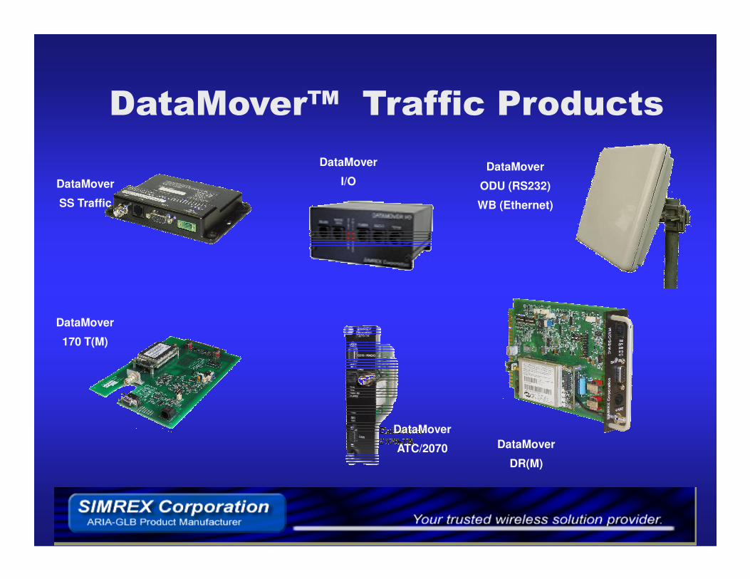
DataMover
ODU (RS232)
WB (Ethernet)
"�����#��$����������! ��
DataMover
SS Traffic
DataMover
I/O
DataMover
DR(M)
DataMover
170 T(M)
DataMover
ATC/2070

��% ������ ���&���!�����' ��("�����#�������' ��)

��% ������ ���&���!�����' ��("�����#�������' ��)
� Fire House based solution� DM SS 900 or 2400 MHz� DM SS 900 or 2400 MHz� Galvanic isolation from intersection� Preempt 1 to 5 Routes� 1 to 5 intersections per route� In fire hall or outdoor antenna supported
"�����*++��,-���!���������' �
���! ��"���� �������
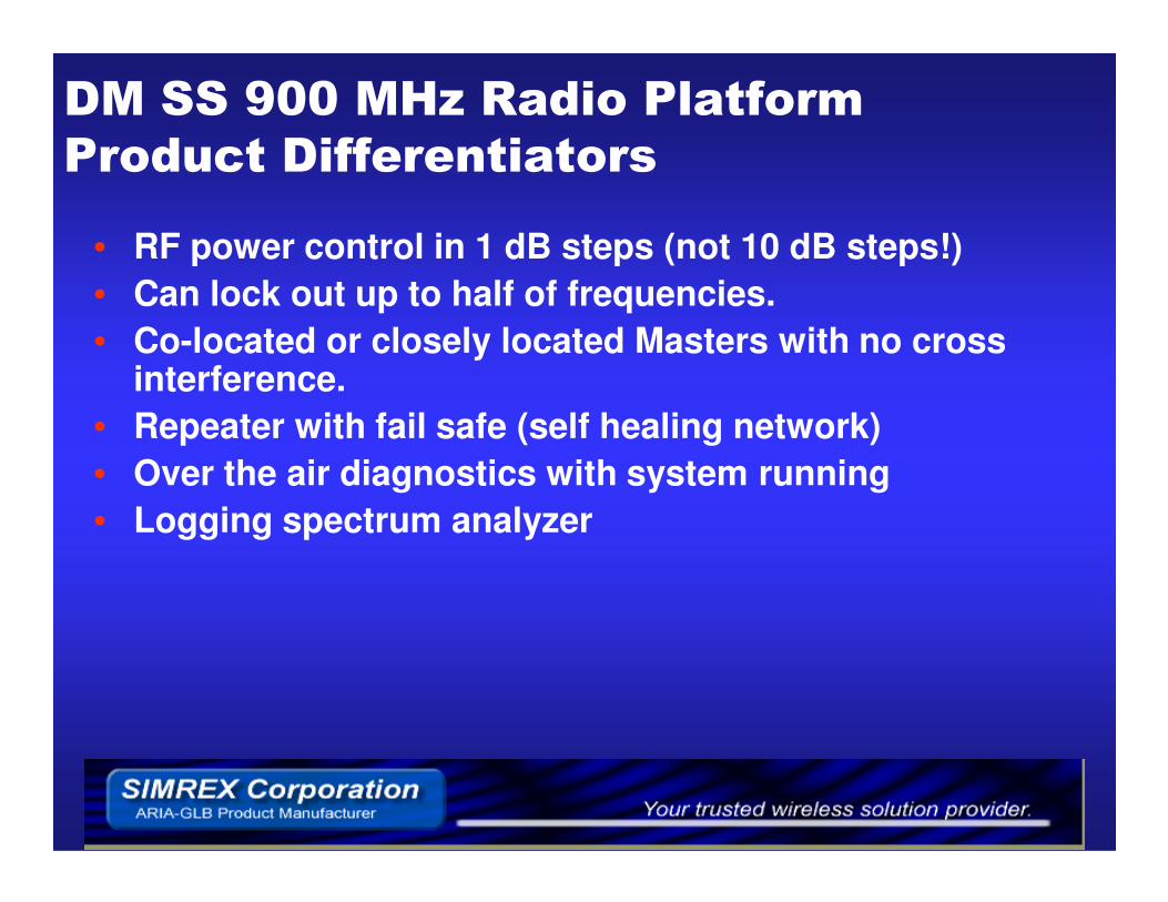
• RF power control in 1 dB steps (not 10 dB steps!)• Can lock out up to half of frequencies. • Co-located or closely located Masters with no cross
interference.• Repeater with fail safe (self healing network)• Over the air diagnostics with system running• Logging spectrum analyzer

"�����#����&
� Ethernet 1.5 - 100 Mbps� 900 / 2400 / 4900 / 5800 MHz� 12.5, 20 or 23 dBi integral antennas� Integral and External Antenna versions� Dual radio capability� 5, 10, 20 or 40 MHz Channels� 5, 10, 20 or 40 MHz Channels� Split antenna capability� POE , power supply and mast clamp included� Router or bridge capability.� Multiple video stream mode.

��' �� �(�)
� Once per day GPS accurate time synchronization� Controller specific time/date message� Once per day contact closure� Vandal resistant� Quick installation� Electromechanical controller mode� Serial messages for Siemens (epac), Econolite and AB3418 � Serial messages for Siemens (epac), Econolite and AB3418
compatible Controllers � L version is GPS antenna only (NMEA GPRMC message)

����� ����
� ������������������� ��������� The Link Budget and Fade Margin� Fresnel zone clearance� Frequency, 900 MHz vs 2400 or 5800 MHz� RF Interference� Antennas� Spectrum analyzer

��!�������!�� !�&� !% �!��
For best range and interference rejection
� Use the narrowest bandwidth possible� Use the lowest speed possible.

������ .�& !���� !���!�������
• Link Budget– Like a balance sheet where you have parameters that add to or
detract from your to have a viable link.
– The units of measure are dB, and dBm
– GOOD: RF power, antenna gain, more receiver sensitivity.
– BAD: cable losses, distance, higher frequency.– BAD: cable losses, distance, higher frequency.

������ .�& !���� !���!�������
• Fade Margin (a.k.a System Operating Margin)– The bottom line of the Link budget.
– The number of dB that the link exceeds or fall short of providing a viable link. + is good - is bad.
• The MATH• The MATHFree Space Loss = 20Log10(Frequency in MHz) + 20Log10 (Distance in Miles) + 36.6
RSL = Tx Power - Tx Cable Loss + Tx Antenna Gain - FSL + Rx Antenna Gain - Rx
Cable Loss

������ .�& !���� !���!�������

��!������� �/ ' �!���!�������What if measured RSSI (signal strength) is less than the predicted received signal level?
This difference is called unmodeled error.Reasons:
• Foliage• Fresnel loss due to terrain or buildings• Other more complex NLOS loss
Catalog these unmodeled error types to build your RF path engineering experience. You can then more easily predict path viability without need of a link test.

���� ���0� �������� �
• Edge diffraction – Like a balance sheet where you have parameters that add to or
detract from your to have a viable link.
– The units of measure are dB, and dBm
– GOOD: RF power, antenna gain, more receiver sensitivity.
– BAD: cable losses, distance, higher frequency.– BAD: cable losses, distance, higher frequency.
• Fade Margin (a.k.a System Operating Margin)– The bottom line of the Link budget.
– The number of dB that the link exceeds or fall short of providing a viable link. + is good - is bad.

���� ���0� �������� �
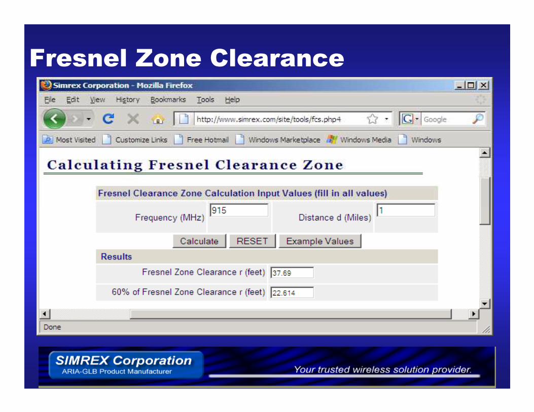
• Direct visual path (line of sight) is important but it is not enough .
• r increases for lower frequencies or longer distance.
Fresnel Zone = 72.1 * Sqrt (dMi / (FreqGHz * 4))
���� ���0� �������� �

���1 � �2�*++�#��34++����56++��,-
• Higher frequencies– Less Fresnel zone clearance required.
– More antenna gain with a specific physical size of antenna.
– Better antenna directivity with a specific size of antenna.
– Shadowed or blocked more easily in most cases.
– Better frequency reuse because of the ability to use narrow beam – Better frequency reuse because of the ability to use narrow beam width antennas.
• Lower frequencies– For the same RF power EIRP and gain of antenna, allow a better
link budget.
– Have less allocated (unlicensed) spectrum

���1 � �2�*++�#��34++����56++��,-
• With all parameters equal, 915 MHz has ~8.5 dB advantage over 2440 MHz.
• With all parameters equal, 915 MHz has ~16 dB advantage over 5800 MHz.
• 900 MHz is good for low bandwidth long range applications. applications.
• 5800 provides excellent directivity (frequency reuse) and wide bandwidth.

���� ������ �
• Co-channel - same channel
• Desensitization – nearby band eg. pagers
• Intermodulation – mixing of 2 signals ���� co-channel

� ������ ����' �!���
• Steer the null of antenna to suppress co-channel or desensitization interference
• Use attenuator to reduce intermodulation

� �� ��
• Gain, dBi vs dB vs dBd• Beamwidth vs gain. • Clearance to pole or nearby objects.• Clamp to element clearance• Use signals from rear of yagi antenna• Splitters.• Splitters.• Lightning Arrestors
� �� ��
• Gain, dBi vs dB vs dBd
� 9 dBd = 11 dBi (2 dB difference)
• Beamwidth vs gain. • Beamwidth vs gain.
� Narrow beamwidth = higher gain

� �� ��
• Clearance to pole or nearby objects.– 18 inches for 900 MHz yagi
– ½ panel dimension for panels.
– Increase distance for objects in front of antenna.
• Mast clamp to Yagi element clearance– As far as possible

� �� ��• Use signals from rear of yagi antenna• Front = 9 dBd, rear = -16 dBd

� �� ��
• Splitter ���� 3.25 dB loss for each antenna
– Consider using rear of yagi.
– 2 way antennas available but higher cost.
• Lightning arrestor• Lightning arrestor
– Low cost = high feed through
• 300V to 600V typical
– Higher cost = low feed through
• 3V to 10 v peak typical

��!������' � ����
� Sensitivity� -108 dBm 1e-6 BER = -110 dBm 1e-5 BER
� FEC and retries improves the rating. Many manufacturers state sensitivity with retries and FEC turned on.
� RF Power Control� 10dB vs 1 dB steps
BER –> Bit Error Rate

�����
� Radio configuration software� Remote Diagnostics� WEB RF path analysis tools� Real time spectrum analyzer
WEB tools at www.simrex.com “free tools”

����� ' �� ���-��
• Horizontal vs vertical polarization noise floor• Out of band vs in band signals.• Desensitization test.• Recording all sweeps and results to file.

��������7
PHOENIX HIGHWAY PRODUCTSwww.phoenixhighwayproducts.com
SIMREX CORPORATIONwww.simrex.com