Wireless Networks and Protocols - web.fe.up.ptmricardo/10_11/wnp/slides/wnp-intro...Introduction to...
82
Intro 1 Wireless Networks and Protocols MAP-TELE Manuel P. Ricardo Faculdade de Engenharia da Universidade do Porto
Transcript of Wireless Networks and Protocols - web.fe.up.ptmricardo/10_11/wnp/slides/wnp-intro...Introduction to...

Intro 1
Wireless Networks and Protocols
MAP-TELE
Manuel P. Ricardo
Faculdade de Engenharia da Universidade do Porto

Intro 2
WNP – Professors
Prof. Adriano Moreira
» Universidade do Minho
Prof. Manuel Ricardo
» Universidade do Porto
» http://www.fe.up.pt/~mricardo
Prof. Rui Aguiar
» Universidade de Aveiro

Intro 33
Syllabus
Introduction to Wireless Networks and Protocols
» What are Wireless networks
» History of wireless networks
» Standards and market issues
» Evolution and trends on wireless networking
Fundamentals of wireless communications
» Transmission
» Wireless data links and medium access control
» Networking
» Mobility concepts and management
Intro 4
Syllabus
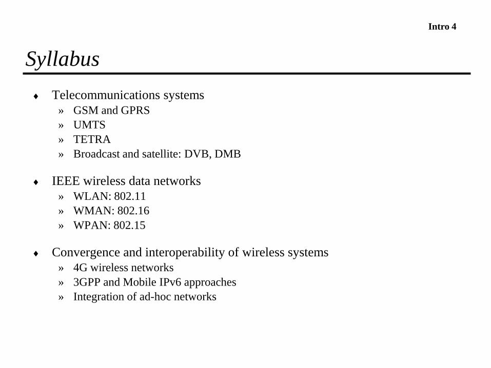
Telecommunications systems
» GSM and GPRS
» UMTS
» TETRA
» Broadcast and satellite: DVB, DMB
IEEE wireless data networks
» WLAN: 802.11
» WMAN: 802.16
» WPAN: 802.15
Convergence and interoperability of wireless systems
» 4G wireless networks
» 3GPP and Mobile IPv6 approaches
» Integration of ad-hoc networks
4

Intro 5
Syllabus
Quality of service
» Characterization and models
» Case studies: 3GPP-QoS, IEEE-QoS, IP-QoS
Support for services and applications
» Web services components: XML and SOAP, UDDI and WSDL
» Services and applications platforms
5

Intro 6
Bibliography
Slides
Recommended papers
Chapters from multiple books» Wireless and Mobile Network Architectures, Yi-Bing Lin, Imrich Chlamtac Wiley, 2001
» Wireless IP and Building the Mobile Internet, Sudhir Dixit, Ramjee Prasad, Artech House, 2002.
» Andrea Goldsmith. Wireless communications. 2006. Cambridge University Press
» The 3G IP Multimedia Subsystem, Merging the Internet and the Cellular Worlds, Gonzalo Camarillo and Miguel a. Garcia-Martin,Wiley, Second Edition, 2005
» Ad-hoc Wireless Networks, Architectures and Protocols, C. Silva Murthy, B. Manoj, Prentice Hall, 2004
» Advanced Wireless Networks - 4G Technologies, S. Glisic, Wiley, 2006.
» Mobile Communications, Jochen Schiller, Second Edition, Addison-Wesley, 2003
» Wireless Communications - Principles and Practice, Theodore S. Rappaport, Second Edition, Prentice Hall, 2002
» Mobile IP Technology and Applications, Stefan Raab and Madhavi W. Chandra, Cisco Press, 2005
» GSM cellular radio telephony, Joachim Tisal, John Wiley & Sons, 1997
» Wireless Communications and Networks, William Stallings, Prentice Hall, 2002
» WCDMA for UMTS : radio acess for third generation mobile communications, Harri Holma, John Wiley & Sons, 2000
» UMTS networks : architecture, mobility and services, Heikki Kaaranen, et al, John Wiley & Sons, 2001
6
Intro 7
Grades
Final Exam - 50%
Review of papers - 20%
Small project - 30%
7
Intro 8
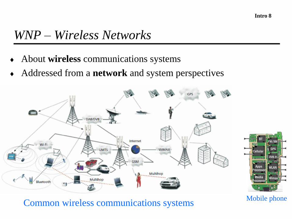
WNP – Wireless Networks
About wireless communications systems
Addressed from a network and system perspectives
Common wireless communications systems
Cellular
AppsProcessor
BT
MediaProcessor
GPS
WLAN
Wimax
DVB-H
FM/XM
Mobile phone
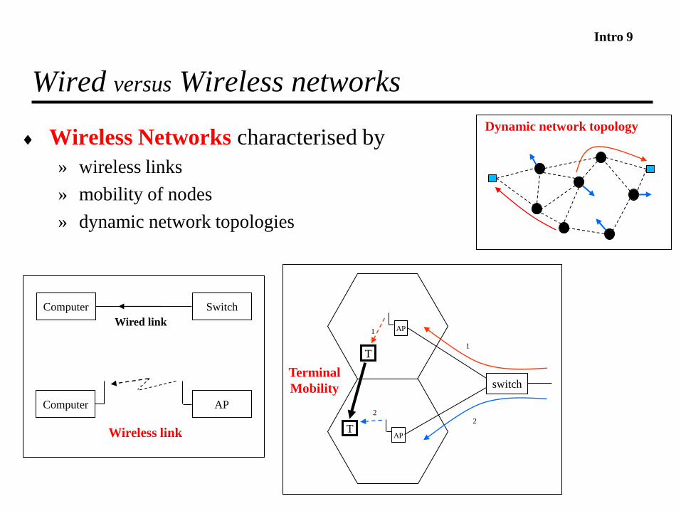
Intro 9
Wireless Networks characterised by
» wireless links
» mobility of nodes
» dynamic network topologies
Wired versus Wireless networks
T
switch
AP
TAP
1
2
1
2
Terminal
Mobility
Computer Switch
Computer AP
Wireless link
Wired link
Dynamic network topology

Intro 10
Wireless Link
Low powers received low SNR
large % of bits possibly received in error
SNR varies with time and positions
variable capacity (bit/s) or variable error ratio (BER)
Broadcast nature
» Information easily accessible by third parties security mechanisms
Pt
Pr

Intro 11
How to obtain low Bit Error Ratio in a Wireless Link?

Intro 12
Mobility
Mobility: characteristic of portable terminals and moving objects
Problems introduced by the mobile terminal
» determine its new location
» Find radio resources in new location
» determine the new path for data deliveryT
switch
AP
TAP
1
2
1
2
Terminal
Mobility
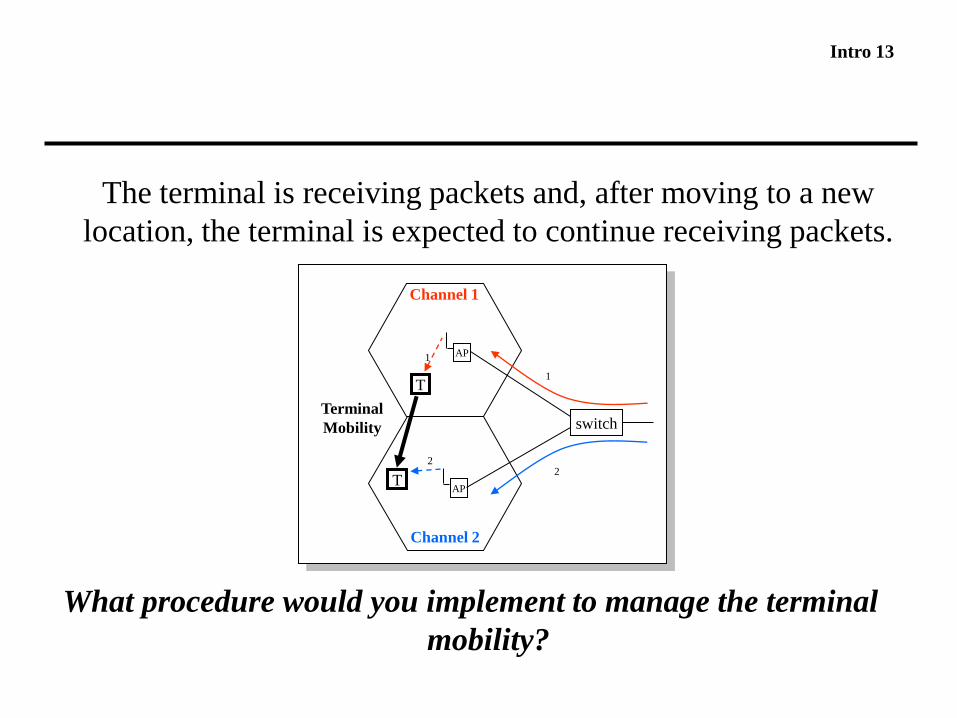
Intro 13
The terminal is receiving packets and, after moving to a new
location, the terminal is expected to continue receiving packets.
What procedure would you implement to manage the terminal
mobility?
T
switch
AP
TAP
1
2
1
2
Terminal
Mobility
Channel 1
Channel 2
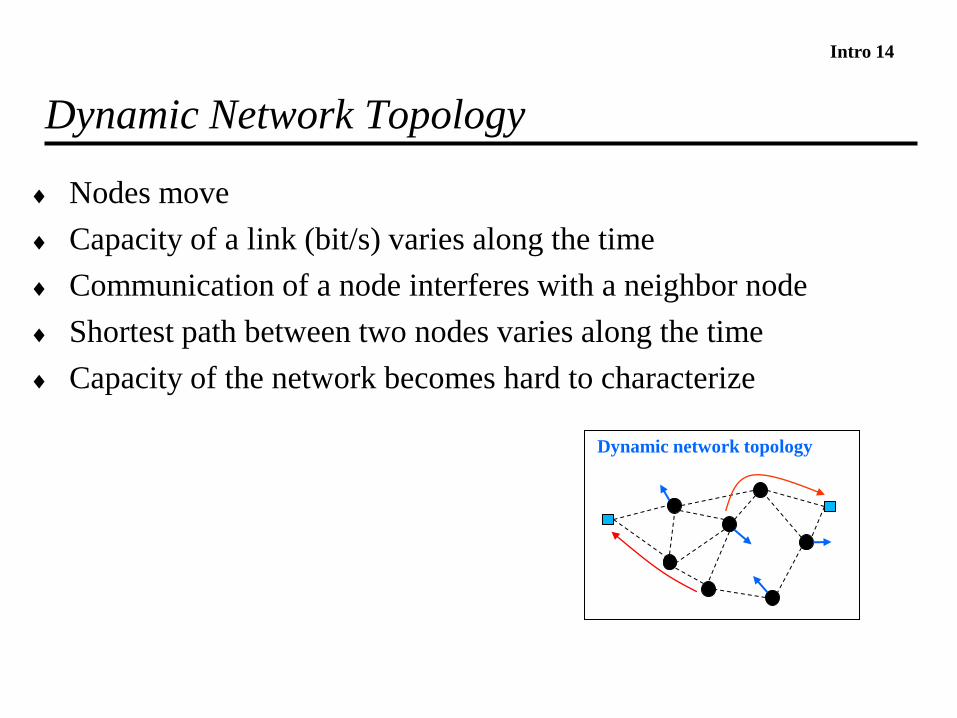
Intro 14
Dynamic Network Topology
Nodes move
Capacity of a link (bit/s) varies along the time
Communication of a node interferes with a neighbor node
Shortest path between two nodes varies along the time
Capacity of the network becomes hard to characterize
Dynamic network topology

Intro 15
History – Past and Radio
Past
» Fire signals used to communicate the fall of Troy to Athens
» 2nd century B.C., sets of torches to transmit characters
» 1793, 3 part semaphores on top hills and towers
» 1837, electric telegraph
Radio transmission
» 1895, first radio transmission
» 1906, amplitude-modulated (AM) radio
» 1920, broadcast of radio news program
» 1928, TV broadcast trials
» 1933, frequency-modulated (FM) radio
» 1946, Swedish police had the first radio phones installed in cars
» 1950, mobile phone with direct dialling

Intro 16
History – Cell, 1st Generation
Cellular topology
» 1950´s, cellular network concept
power of transmitted signal falls with square of distance
2 users can operate on same frequency at separate locations
» 1971, Finland, ARP, first public commercial cellular, mobile network
1st Generation Analogue, Frequency Division Multiplexing
» 1982, NMT network covering Finland/Sweden/Norway/Denmark
» 1983, AMPS in America
» 1985, TACS, Total Access Communications Service, in Europe

Intro 17
History – Packet Radio
1971, ALOHANET packet radio
» computers communicate with central HUB
1980's ad-hoc, self-configurable packet networks
1985, Wireless LANs authorized to use ISM bands
1997, first WLAN standard

Intro 18
History – 2nd and 3rd Generation
2nd Generation
digital transmission and signalling; ISDN based
» 1982, specification GSM is started
» Early 1990´s
– Europe: GSM
– USA: D-AMPS, cdmaOne
– Japan: Personal Digital Cellular (PDC)
3G systems
aimed at multimedia communication
» 2001, Japan, first implementation of 3G systems
Intro 19
Type of Networks
WPAN - Wireless Personal Area Networks
» short distances among a private group of devices
WLAN - Wireless Local Area Networks
» areas such as an home, office or group of buildings
WMAN - Wireless Metropolitan Area Networks
» from several blocks of buildings to entire cities
PLMN - Public Land Mobile Networks
» regions and countries
Broadcast
» single direction, audio and video
Intro 20
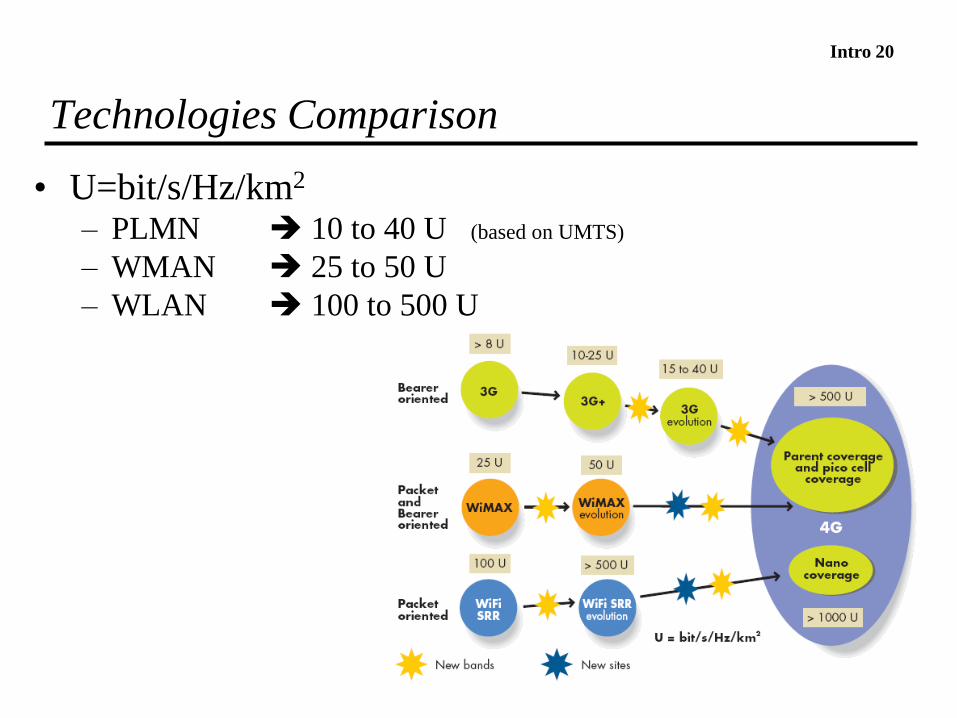
Technologies Comparison
• U=bit/s/Hz/km2
– PLMN 10 to 40 U (based on UMTS)
– WMAN 25 to 50 U
– WLAN 100 to 500 U

Intro 21
Evolution of Technologies
Rate(bit/s)
Mobility(km/s)
2G
3G
4G
802.11b WLAN
2G Cellular
802.11n
Wimax/3G
Intro 22
Standard Organizations - IEEE
IEEE - Institute of Electrical and Electronics Engineers
802 Standards for Local /Metropolitan Area Network, wired and wireless
» Wireless LANs (802.11)
» Wireless Personal Area Networks (802.15),
» Broadband Wireless Metropolitan Area Networks (802.16)
» Mobile Broadband Wireless Access (802.20)
» Media Independent Handoff Working Group (802.21)
http://standards.ieee.org/getieee802/index.html
Layers 1 and 2 of the OSI communications model
Below the IP communications layer

Intro 23
Standards – 3GPP
Scope of 3GPP
» Specifications for the 3rd Generation mobile system
» Maintain GSM, GPRS and EDGE
» Specifications developed by Technical Specification Groups (TSG)
http://www.3gpp.org

Intro 24
Standards - IETF
http://www.ietf.org
Defines standards for the Internet, including
» TCP/IP
» key services
» routing protocols
» deployment of IP over technologies
Intro 25
Standards - Other
ITU - Worldwide
ETSI - Europe
3GPP2 – American 3GPP

Intro 26
Homework
1. Review slides
2. Read from Schiller
» Chap. 1
3. Read from Goldsmith
» Chap. 1
Intro 27
How does an EM wave propagate in a wireless channel?
What is an antenna and an antenna gain?
What is shadowing, reflection, refraction, scattering, and
diffraction?
What is path loss? How to model it?
What is the simple path loss model?
How to model shadowing?
What is multipath? How does it affect the power received? How
does it affect narrowband and wideband communications?
What is the maximum theoretical capacity of a wireless channel?

Intro 28
Electromagnetic Wave
,/10*3 8 smc speed of light
l - wavelength
d
c
t=t1
d=d1
t
T1/ f = Period
fc= 3 GHz l 10 cm
fc= 1 GHz l 30 cm
fc= 300 MHz l 1m
Intro 29
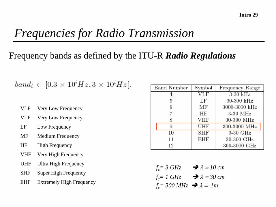
Frequencies for Radio Transmission
Frequency bands as defined by the ITU-R Radio Regulations
VLF Very Low Frequency
VLF Very Low Frequency
LF Low Frequency
MF Medium Frequency
HF High Frequency
VHF Very High Frequency
UHF Ultra High Frequency
SHF Super High Frequency
EHF Extremely High Frequency
fc= 3 GHz l 10 cm
fc= 1 GHz l 30 cm
fc= 300 MHz l 1m

Intro 30
Wireless Systems in Europe
• In PortugalANACOM attributes the frequencies
http://www.anacom.pt
• FWAFixed Wireless Access
• ISMIndustrial, Scientific and Medical

Intro 31
How does the power of a received signal depend on the
distance and wavelength (l)?
Intro 32
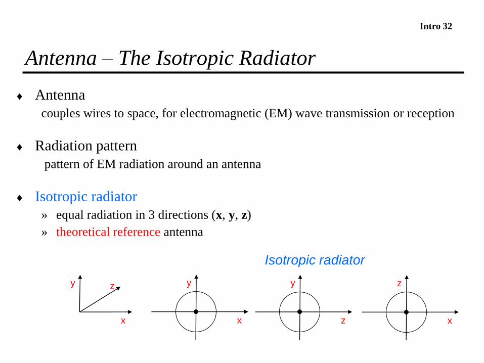
Antenna – The Isotropic Radiator
Antenna
couples wires to space, for electromagnetic (EM) wave transmission or reception
Radiation pattern
pattern of EM radiation around an antenna
Isotropic radiator
» equal radiation in 3 directions (x, y, z)
» theoretical reference antenna
Isotropic radiator
y
x
y
z
z
x
y
x
z
Intro 33
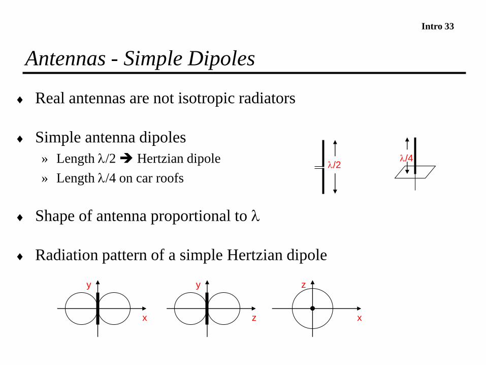
Antennas - Simple Dipoles
Real antennas are not isotropic radiators
Simple antenna dipoles
» Length l/2 Hertzian dipole
» Length l/4 on car roofs
Shape of antenna proportional to l
Radiation pattern of a simple Hertzian dipole
x
y
z
y
x
z
l/4l/2

Intro 34
Antenna Gain, EIRP
Antenna Gain
» maximum power in direction of the main lobe (Pmain_lobe), compared to
power of an isotropic radiator (Pt) transmitting the same average power
» baloon
Effective Isotropic Radiate Power (EIRP)
» EIRP= Pt Gt
» Maximum radiated power in the direction of maximum antenna gain
2
_ 4
l
e
t
lobemain A
P
PG
Ae – Antenna aperture
depends on physical antenna characteristics
Intro 35
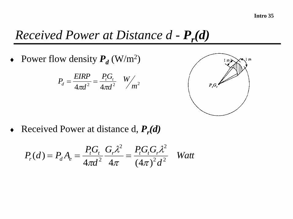
Received Power at Distance d - Pr(d)
Power flow density Pd (W/m2)
Received Power at distance d, Pr(d)
Wattd
GGPG
d
GPAPdP rttrtt
edr 22
22
2 )4(44)(
l
l
222 44 mW
d
GP
d
EIRPP tt
d

Intro 36
Transmit and Receive Signal Models
Transmitted signal modeled as
The received signal
if s(t) is transmitted through a time-invariant channel c then
where
» c(t)=hl(t) is the equivalent lowpass impulse response of the channel
» Hl(f) is the equivalent lowpass frequency response of the channel
Intro 37
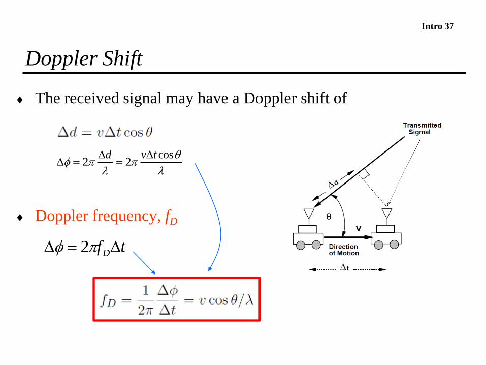
Doppler Shift
The received signal may have a Doppler shift of
Doppler frequency, fD
l
l
cos22
tvd
tfD 2
Intro 38
Suppose you are moving towards the transmitter.
Will the perceived frequency of the carrier increase or decrease?

Intro 39
W, dBW, dBm, dB, Gain
dBmdBmdBWdBWWW
W
W
srsrsr
s
r
dB PPPPPPP
PGain ---
log.10log.10log.10
W
W
dBW r
r
r PW
PP log.10
1log.10
mW
P
rWr
dBmP
1log.10
s
JW
Time
EnergyPowerP
Wr 1
11,,
dBmdBmdBWdBW rsrsdBdBdB PPPPGainAtenuationLoss ---
Intro 40
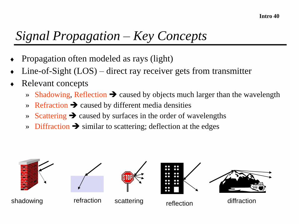
Signal Propagation – Key Concepts
Propagation often modeled as rays (light)
Line-of-Sight (LOS) – direct ray receiver gets from transmitter
Relevant concepts
» Shadowing, Reflection caused by objects much larger than the wavelength
» Refraction caused by different media densities
» Scattering caused by surfaces in the order of wavelengths
» Diffraction similar to scattering; deflection at the edges
reflectionscattering diffractionshadowing refraction
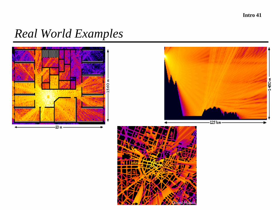
Intro 41
Real World Examples
Intro 42
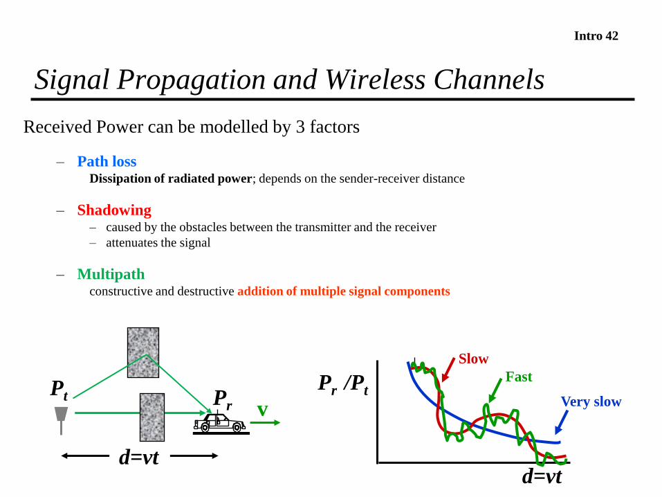
Signal Propagation and Wireless Channels
Received Power can be modelled by 3 factors
– Path lossDissipation of radiated power; depends on the sender-receiver distance
– Shadowing– caused by the obstacles between the transmitter and the receiver
– attenuates the signal
– Multipathconstructive and destructive addition of multiple signal components
d=vt
Pr /PtVery slow
Slow
Fast
PrPt
d=vt
v
Intro 43
Path Loss Models
Free space path loss model
Too simple
Ray tracing models
Demand site-specific information
Empirical models
Do not generalize to other environments
Simplified model
Good for high-level analysis

Intro 44
Path Loss - Free Space (LOS) Model
Path loss (PL) for unobstructed LOS path
Power falls off
» Proportional to 1/d2
» Proportional to l2 (inversely proportional to f 2)
d=vt
)log(.204
log.20 dG
PG l
dB -
l
PGdB
(dB)
log(d)
Path lossrsl GGG
Intro 45
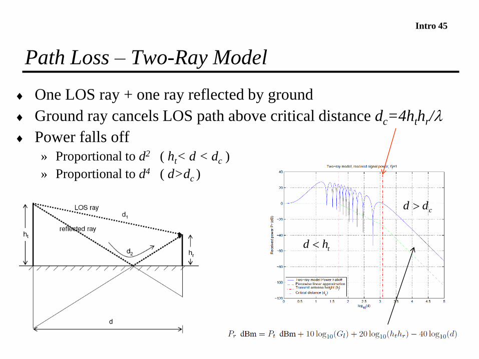
Path Loss – Two-Ray Model
One LOS ray + one ray reflected by ground
Ground ray cancels LOS path above critical distance dc=4hthr/l
Power falls off
» Proportional to d2 ( ht< d < dc )
» Proportional to d4 ( d>dc )
thd
cdd

Intro 46
Path – Loss Empirical Models
Okumura model
» Empirically based (site/freq specific); 150-1500 MHz, Tokyo
» Empirical plots
Hata model
Analytical approximation to Okumura model
Cost 231 Model
Extension Hata model to higher frequency (1.5 GHz < fc < 2 GHz )
Walfish/Bertoni
Extends Cost 231 to include diffraction from rooftops

Intro 47
Path Loss – Indoor Factors
Walls, floors, layout of rooms, location and type of objects
» Impact on the path loss
» The losses introduced must be added to the free space losses

Intro 48
Path Loss - Simplified Model
Used when path loss is dominated by reflections
K
» determined by measurement at
» or,
Path loss exponent g is determined empirically
l100 d
82,0
g
g
d
dKPP sr
dBmdBm srdB PPKdd - 0
Intro 49
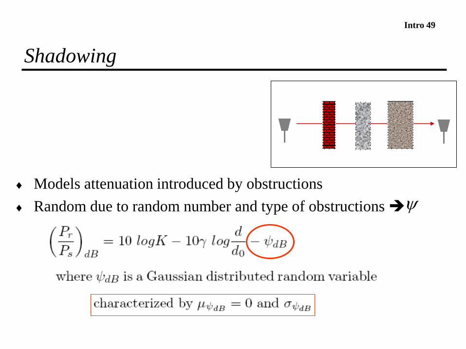
Shadowing
Models attenuation introduced by obstructions
Random due to random number and type of obstructions

Intro 50
Combined Path Loss and Shadowing
),0(~
,log10log10)(
2
0
1010
g
N
d
dKdB
P
P
dB
dB
s
r -
-
10logK
Pr/Pt
(dB)
log(d)
Path loss
Shadowing + Path loss
0 (d=d0)

Intro 51
Outage Probability and Cell Coverage Area
Path loss model circular cells
Path loss + shadowing amoeba cells
tradeoff between coverage and interference
Outage probability
Probability received power below given minimum
Cell coverage area % of cell locations at desired power
» Increases as shadowing variance () decreases
» Large % indicates interference to other cells

Intro 52
Statistical Multipath Model
Multipath multiple rays
» multiple delays from transmitter to receiver
» time delay spread
Multipath channel has a time-varying gain
» caused by the transmitter / receiver movements
» location of reflectors which originate the multipaths
0
1

Intro 53
Multipath – Narrowband Channel
In a narrowband channel
low B low symbol rate (symbol/s) large time/symbol (1/B)
multipath components arrive in the time period of their symbol
Assume also u(t-i) u(t)
No spreading in time (no distortion)
Intro 54
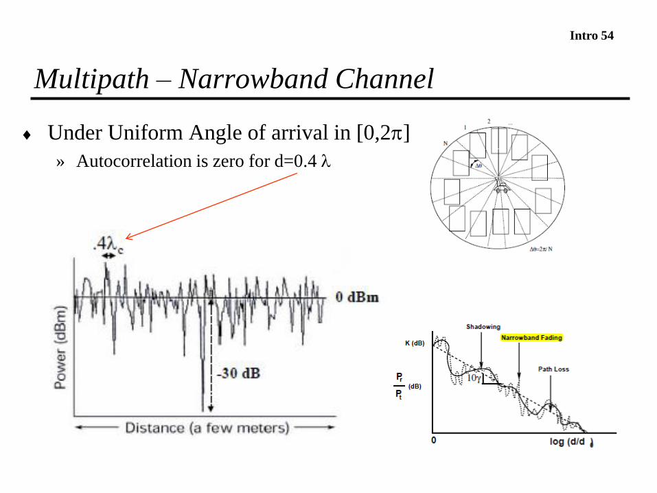
Multipath – Narrowband Channel
Under Uniform Angle of arrival in [0,2]
» Autocorrelation is zero for d=0.4 l
Intro 55Multipath - Narrowband Channel –
Rayleigh Fading
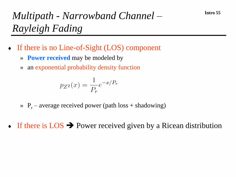
If there is no Line-of-Sight (LOS) component
» Power received may be modeled by
» an exponential probability density function
» Pr – average received power (path loss + shadowing)
If there is LOS Power received given by a Ricean distribution
Intro 56
Suppose you are the receiver.
What information does this exponential distribution provide to you?
Intro 57
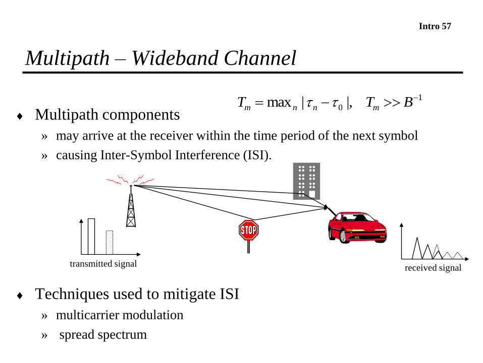
Multipath – Wideband Channel
Multipath components
» may arrive at the receiver within the time period of the next symbol
» causing Inter-Symbol Interference (ISI).
Techniques used to mitigate ISI
» multicarrier modulation
» spread spectrum
transmitted signal received signal
1
0 |,|max -- BTT mnnm
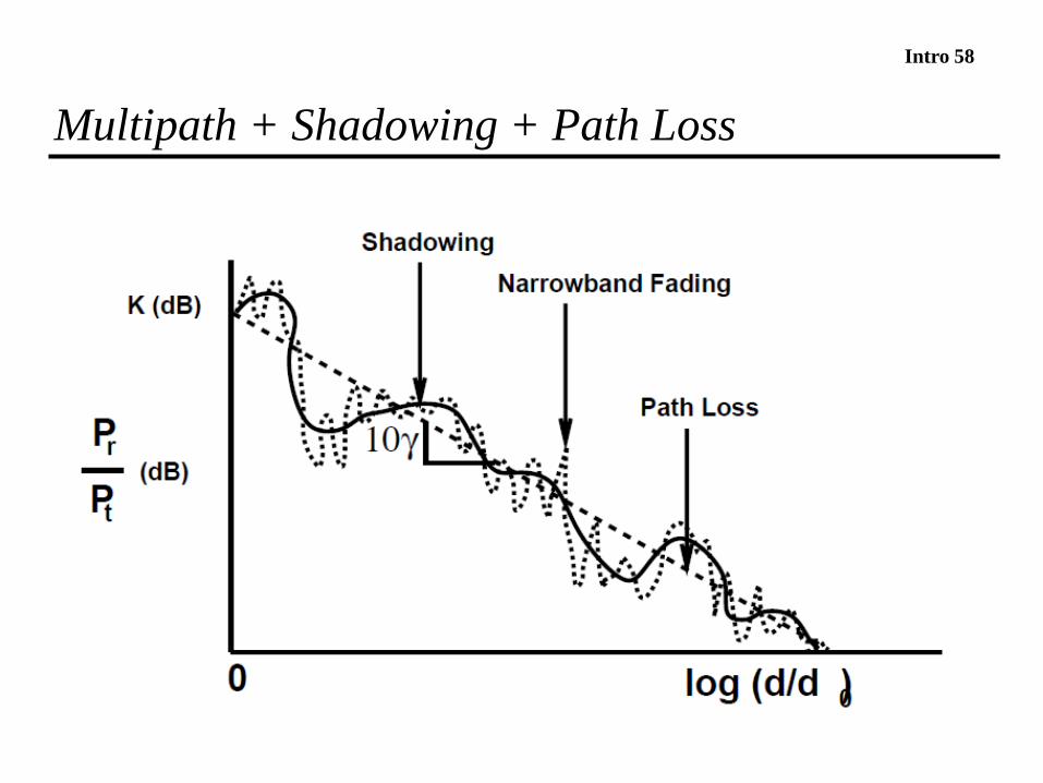
Intro 58
Multipath + Shadowing + Path Loss

Intro 59
Capacity of an Wireless Channel
Assuming Additive White Gaussion Noise (AWGN)
» Given by Shannon´s law
N0 – Noise power spectral density
Capacity in a fading channel (shadowing + multipath)
usually smaller than the capacity of an AWGN channel
(bit/s)
Intro 60
Homework
1. Review slides
» use them to guide you through the recommended books
2. Read from Goldsmith
» Chap. 2, Chap. 3 (sections 3.1, 3.2, 3.3), Chap. 4 (section 4.1)
3. Read from Schiller
» Chap. 2 (sections 2.1, 2.2, 2.3, 2,4)
4. Rappaport also provides an excellent description of these topics
» See Chap. 3 and Chap. 4

Intro 61
How to transmit bits in a carrier? What are the modulations
commonly used in wireless networks?
How does the BER depend on the modulation and SNR?
What is a code? What are its benefits for wireless
communications? Why is interleaving combined with codes?
What is multicarrier modulation? What is OFDM? Why is it so
important? How to implement it with DFTs?
What is spread spectrum? How does the RAKE receive work?
What is Software Defined Radio?
What are the main purposes of Cognitive Radio?

Intro 62
Digital Modulation/Demodulation
Modulation: maps information bits into an analogue signal (carrier)
Demodulation: determines the bit sequence based on received signal
Two categories of digital modulation
» Amplitude modulation - α(t) / Phase modulation - θ(t)
» Frequency modulation - f(t)
Modulated signal s(t)
Signal trasmited over time symbol i si(t)
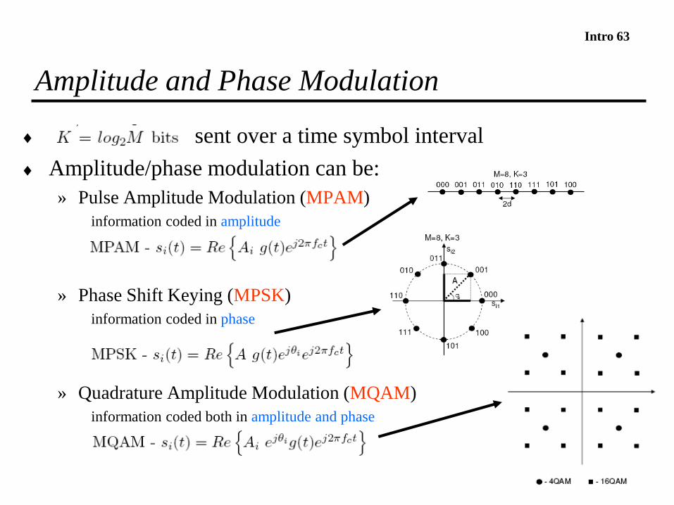
Intro 63
Amplitude and Phase Modulation
sent over a time symbol interval
Amplitude/phase modulation can be:
» Pulse Amplitude Modulation (MPAM)
information coded in amplitude
» Phase Shift Keying (MPSK)
information coded in phase
» Quadrature Amplitude Modulation (MQAM)
information coded both in amplitude and phase
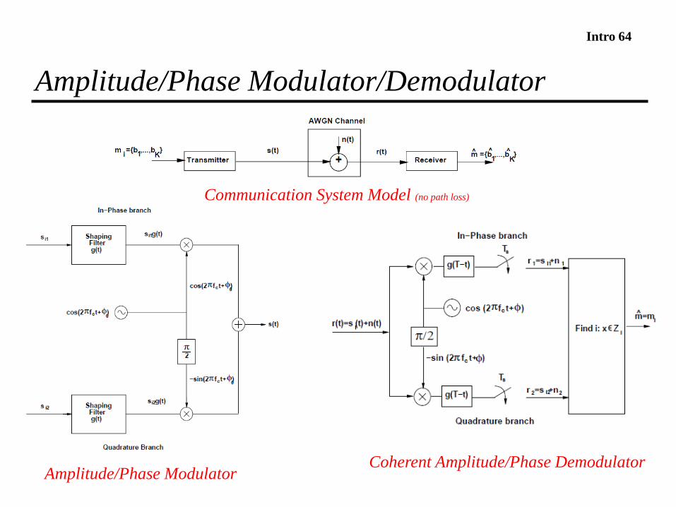
Intro 64
Amplitude/Phase Modulator/Demodulator
Coherent Amplitude/Phase DemodulatorAmplitude/Phase Modulator
Communication System Model (no path loss)
Intro 65
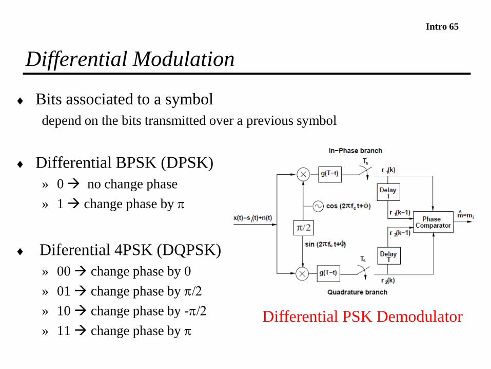
Differential Modulation
Bits associated to a symbol
depend on the bits transmitted over a previous symbol
Differential BPSK (DPSK)
» 0 no change phase
» 1 change phase by
Diferential 4PSK (DQPSK)
» 00 change phase by 0
» 01 change phase by /2
» 10 change phase by -/2
» 11 change phase by Differential PSK Demodulator
Intro 66
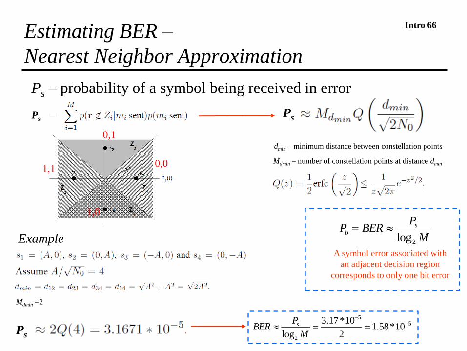
Ps
Estimating BER –
Nearest Neighbor Approximation
dmin – minimum distance between constellation points
Mdmin – number of constellation points at distance dmin
Example
Mdmin =2
M
PBERP s
b
2log
55
2
10*58.12
10*17.3
log
--
M
PBER s
A symbol error associated with
an adjacent decision region
corresponds to only one bit error
Ps – probability of a symbol being received in error
Ps
0,0
1,0
1,1
Ps
0,1
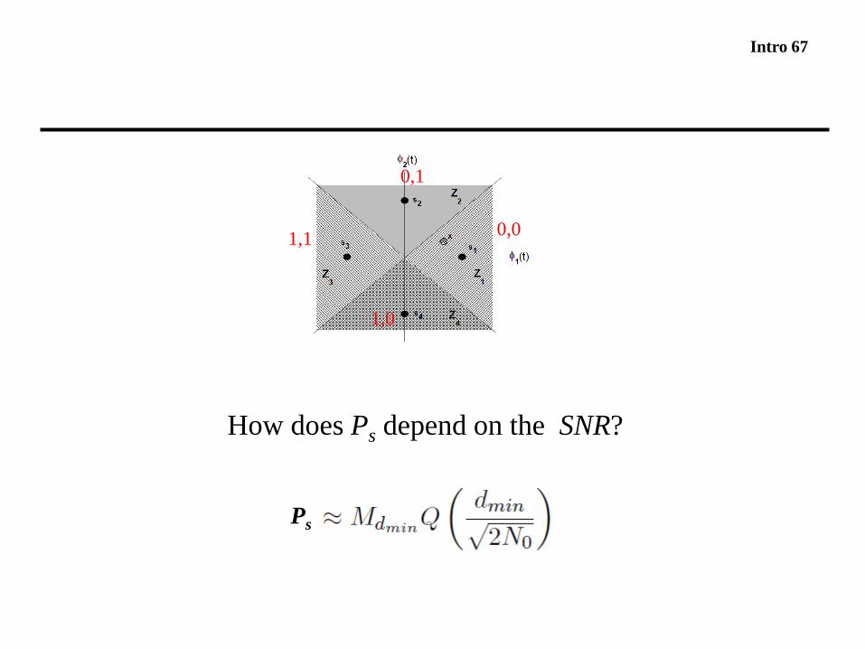
Intro 67
How does Ps depend on the SNR?
0,0
1,0
1,1
0,1
Ps
Intro 68
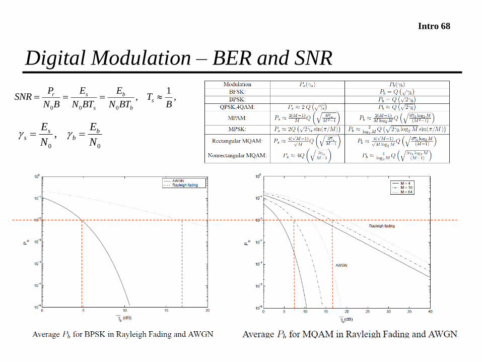
Digital Modulation – BER and SNR
,1
,000 B
TBTN
E
BTN
E
BN
PSNR s
b
b
s
sr
00
,N
E
N
E bb
ss gg

Intro 69
Coding
Coding enables bit errors to be either
detected or corrected by receiver
Coding gain, Cg
the amount of SNR that can be reduced for a given Pb
Coding rate, k/n
» Code generates n coded bits for every k uncoded bits
» If channel+modulation enable the transmission of R bit/s
» Information rate = R * k/n bit/s

Intro 70
Coding in Wireless Channels
Codes designed for AWGN channels » do not work well on fading channels
» cannot correct the long error bursts that may occur in fading
Codes for fading channels are usually » based on an AWGN channel code
» combined with interleaving
» objective spread error bursts over multiple codewords
Interleaving
Rayleigh
Intro 71
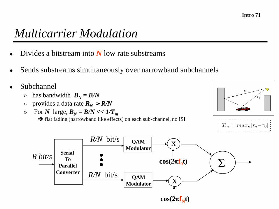
Multicarrier Modulation
Divides a bitstream into N low rate substreams
Sends substreams simultaneously over narrowband subchannels
Subchannel» has bandwidth BN = B/N
» provides a data rate RN R/N
» For N large, BN = B/N << 1/Tm
flat fading (narrowband like effects) on each sub-channel, no ISI
x
cos(2f0t)
x
cos(2fNt)
SR bit/s
R/N bit/s
R/N bit/s
QAM
Modulator
QAM
Modulator
Serial
To
Parallel
Converter
0
1
Intro 72
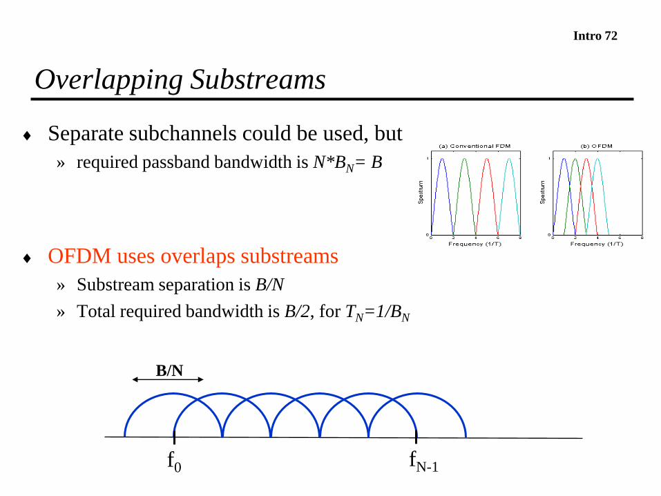
Overlapping Substreams
Separate subchannels could be used, but
» required passband bandwidth is N*BN= B
OFDM uses overlaps substreams
» Substream separation is B/N
» Total required bandwidth is B/2, for TN=1/BN
f0 fN-1
B/N
Intro 73
Most of the recent wireless communications tecnologies are
adopting OFDM (e.g. WLAN, WIMAX, LTE).
Why?

Intro 74
OFDM uses Discrete Fourier Transforms
Discrete Fourier transforms given by
Circular convolution
Intro 75
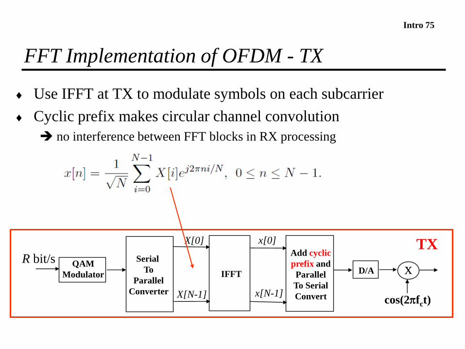
FFT Implementation of OFDM - TX
Use IFFT at TX to modulate symbols on each subcarrier
Cyclic prefix makes circular channel convolution
no interference between FFT blocks in RX processing
x
cos(2fct)
R bit/s QAM
Modulator
Serial
To
Parallel
Converter
IFFT
X[0] x[0]
x[N-1]
Add cyclic
prefix and
Parallel
To Serial
Convert
D/A
TX
X[N-1]
Intro 76
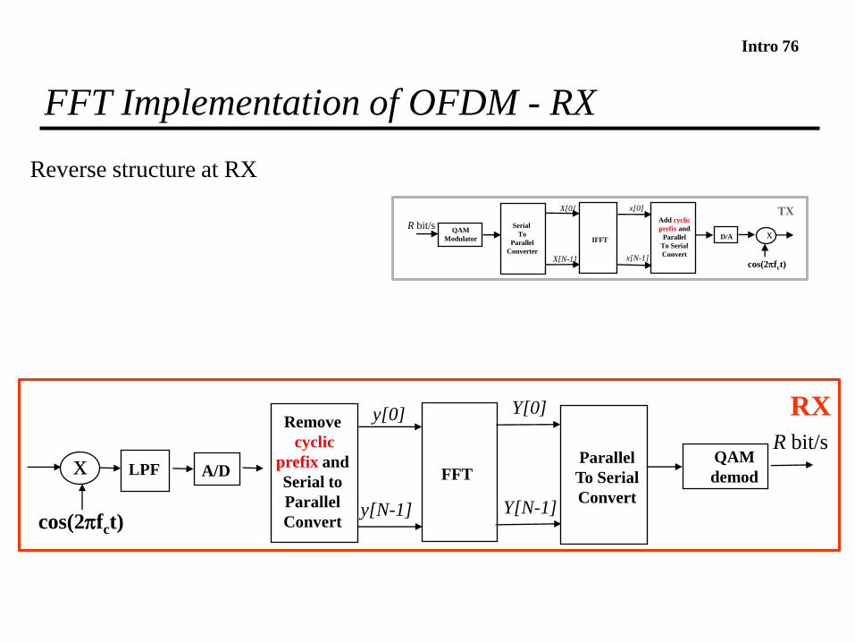
FFT Implementation of OFDM - RX
Reverse structure at RX
x
cos(2fct)
R bit/sQAM
demodFFT
Y[0]
Y[N-1]
y[0]
y[N-1]
Remove
cyclic
prefix and
Serial to
Parallel
Convert
A/DLPFParallel
To Serial
Convert
RX
x
cos(2fct)
R bit/sQAM
Modulator
Serial
To
Parallel
Converter
IFFT
X[0] x[0]
x[N-1]
Add cyclic
prefix and
Parallel
To Serial
Convert
D/A
TX
X[N-1]
Intro 77
Spread Spectrum
Spread spectrum techniques
» hide the information signal below the noise floor
» mitigate inter-symbol interferences
» combine multipath components
The spread spectrum techniques
» multiply the information signal by a spreading code
Intro 78
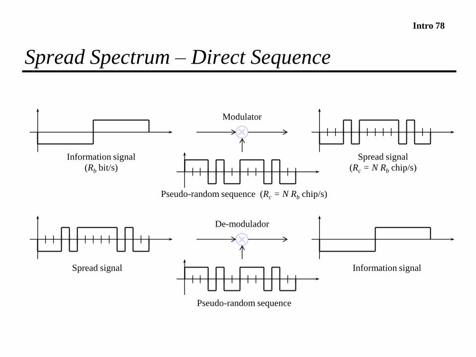
Spread Spectrum – Direct Sequence
Modulator
Information signal
(Rb bit/s)
Spread signal
(Rc = N Rb chip/s)
Pseudo-random sequence (Rc = N Rb chip/s)
De-modulador
Pseudo-random sequence
Spread signal Information signal

Intro 79Direct Sequence Spread Spectrum –
Immunity to Interferences
P
original signal
P
fspread signal
interferencesf
P
f
P
Received signalf
Preceived
signal
signal
wideband interference
narrowband interferencef
Signal after de-spreading

Intro 80
Software Defined Radio
Software Defined Radio
aims at implementing the radio functions in software
Digital Signal Processors being integrated with microcontroller
better integration of radio and communications functions

Intro 81
Cognitive Radio
Cognitive radio
» fills unused bands
» avoids interferences
» increases spectral efficiency
Paves the way to
» dynamic spectrum licensing
» secondary markets in spectrum usage
Intro 82
Homework
1. Review slides
1. Detailed information about these topics can found at the
Goldsmith’s book
» Chap. 5 (sections 5.1, 5.2, 5.3, 5.5)
» Chap. 6 (sections 6.1, 6.3)
» Chap. 7 (sections 7.1, 7.2)
» Chap. 8 (section 8.1)
» Chap. 9 (section 9.1)
» Chap. 12 (sections 12.1, 12.2, 12.4)
» Chap. 13 (sections 13.1, 13.2, 13.3)