Wireless Network Deployment Guidelines - nxp.com · 4.2 Antenna Issues and Types 21 4.2.1 Isotropic...
42
Wireless Network Deployment Guidelines Application Note JN-AN-1059 Revision 1.2 18 December 2013
Transcript of Wireless Network Deployment Guidelines - nxp.com · 4.2 Antenna Issues and Types 21 4.2.1 Isotropic...
Wireless Network Deployment GuidelinesApplication Note
JN-AN-1059
Revision 1.2
18 December 2013

Wireless Network Deployment GuidelinesApplication Note
2 © NXP Laboratories UK 2013 JN-AN-1059 v1.2

Wireless Network Deployment GuidelinesApplication Note
Contents
About this Document 5Organisation 5
Conventions 6
Acronyms and Abbreviations 6
Related Documents 7
Support Resources 7
Trademarks 7
1. Introduction 91.1 Protocol Standards 9
1.2 Wires vs Wireless 10
2. Radio Channel Basics 112.1 The 2.4-GHz ISM Band - Living with Your Neighbours 11
2.2 Transmit Power, Receive Sensitivity and Range 12
3. Antenna Options 153.1 Modules with Integral Antenna 15
3.2 Modules with RF Connector 16
4. Antenna Properties and Types 194.1 Antenna Directivity 19
4.2 Antenna Issues and Types 214.2.1 Isotropic Antenna 21
4.2.2 Half-Wave Dipole Antenna 22
4.2.3 Yagi Antenna 23
4.3 Antenna Gain 24
4.4 Antenna Polarisation 25
4.5 Antenna Commissioning 25
5. Reflections, Obstructions and Multipath 27
6. Deployment Guidelines 296.1 General Guidelines 29
6.2 Multipath and Fade Margins 29
6.3 Open Space Guidelines 30
6.4 Indoor Environment Guidelines 31
JN-AN-1059 v1.2 © NXP Laboratories UK 2013 3
Chapter 1
6.5 Point-to-Point Link Guidelines 33
7. The Benefits of Mesh Networking 35
8. Sharing Channels with Other Radio Systems 37
9. Deployment Checklist 39
4 © NXP Laboratories UK 2013 JN-AN-1059 v1.2

Wireless Network Deployment GuidelinesApplication Note
About this Document
This document provides basic guidelines for the deployment of a wireless network based on the IEEE 802.15.4 protocol - for example, this could be a ZigBee PRO or JenNet-IP network which is built on IEEE 802.15.4. It introduces some of the fundamental concepts and issues related to radio communication in these systems. As such, it will act as a useful reference point for network installation and maintenance personnel who are not experts in the radio/wireless domain.
Organisation
This document consists of 9 chapters, as follows:
Chapter 1 presents a short introduction to wireless networks
Chapter 2 introduces the basic concepts of radio communication, particularly those relevant to wireless networks.
Chapter 3 describes the antenna options for modules featuring NXP JN51xx wireless microcontrollers.
Chapter 4 presents the main properties of antennae, as well as different antenna types.
Chapter 5 addresses factors that affect the propagation of radio signals.
Chapter 6 presents guidelines for deploying wireless network nodes in different environments.
Chapter 7 introduces the advantages of using a wireless network with a mesh topology.
Chapter 8 outlines the issues involved in sharing radio frequency bands with other radio systems.
Chapter 9 presents a checklist of the main deployment guidelines.
JN-AN-1059 v1.2 © NXP Laboratories UK 2013 5

About this Document
Conventions
Files, folders, functions and parameter types are represented in bold type.
Function parameters are represented in italics type.
Code fragments are represented in the Courier New typeface.
Acronyms and Abbreviations
IEEE Institute of Electrical and Electronics Engineers
ISM Industrial, Scientific and Medical
LOS Line Of Sight
PAN Personal Area Network
PER Packet Error Rate
RF Radio Frequency
WLAN Wireless Local Area Network
This is a Tip. It indicates useful or practical information.
This is a Note. It highlights important additional information.
This is a Caution. It warns of situations that may result in equipment malfunction or damage.
6 © NXP Laboratories UK 2013 JN-AN-1059 v1.2
Wireless Network Deployment GuidelinesApplication Note
Related Documents
[1] ZigBee PRO Stack User Guide (JN-UG-3048)
[2] Module Development Reference Manual (JN-RM-2006)
[3] Application Note “Antennae for use with JN51xx” (JN-AN-1030)
[4] Application Note “Packet Error Rate Testing for JN516x” (JN-AN-1175)
[5] "The Mobile Radio Propagation Channel", David Parsons, Pentech Press 1992, ISBN0-7273-1316-9
Support Resources
To access online support resources such as SDKs, Application Notes and User Guides, visit the Wireless Connectivity TechZone:
www.nxp.com/techzones/wireless-connectivity
For JN514x resources, visit the NXP/Jennic web site: www.jennic.com/support
Trademarks
All trademarks are the property of their respective owners.
“JenNet” and “JenNet-IP” are trademarks of NXP B.V..
JN-AN-1059 v1.2 © NXP Laboratories UK 2013 7

About this Document
8 © NXP Laboratories UK 2013 JN-AN-1059 v1.2

Wireless Network Deployment GuidelinesApplication Note
1. Introduction
The IEEE 802.15.4 wireless network standard has paved the way for a revolution in the implementation of PANs (Personal Area Networks), with the traditional wiring used to connect sensors and switches being replaced with radio links. This wireless solution is hugely attractive in helping to reduce construction costs of new buildings. Furthermore, a mesh radio system (such as a ZigBee PRO network) can be installed in older buildings, permitting improvements that would be impractical with traditional wiring methods.
For the majority of installations, the siting of individual radio nodes will be done without expert radio knowledge. This Application Note outlines the basic considerations and rules to enable successful installations in such cases.
1.1 Protocol Standards
You can develop a wireless network based directly on the IEEE 802.15.4 protocol standard or based on another standard which is itself based on IEEE 802.15.4 - for example, ZigBee PRO or JenNet-IP, which both offer additional functionality over IEEE 802.15.4.
Radio equipment developed to the IEEE 802.15.4 standard ensures interoperability - that is, radio components from different sources can operate together. When installing a radio network, adherence to the required standard is essential for interoperability. The equipment may be required to meet multiple standards - for example, ZigBee equipment must meet both the IEEE 802.15.4 and ZigBee standards.
NXP's JN51xx range of single-chip IEEE 802.15.4-based devices allows the development of network products that meet the following standards:
IEEE 802.15.4
JenNet-IP
ZigBee PRO
ZigBee Remote Control (RF4CE)
JN-AN-1059 v1.2 © NXP Laboratories UK 2013 9

Chapter 1Introduction
1.2 Wires vs Wireless
The notion of a wired link is a familiar one - a cable joins two connectors, and a link is made. The link is normally broken by disconnection at either end (or rarely if the intervening cable is broken, perhaps by accident). Thus, the physical environment of a wired link (e.g. the office) usually plays little or no part in determining the state of the link.
For a radio link, the situation is different. There is no cable to act as a secure and reliable signal path. The link must be made across free-space, through walls, people and other obstructions. This environment may be constantly changing, such as in a busy working area with people moving around. Furthermore, the environment may already contain other wireless systems that seek to "share" the same airwaves as the system to be deployed. In short, in wireless system deployment, there is usually little or no control over the deployment environment, which can vary widely.
So, what can be done to ensure that your network is deployed efficiently? First consider listening to an FM radio. Here you are enjoying the result of an established radio link deployment. The engineers who built this system have used high towers on which they have located their transmit antennae. They have engineered the system to ensure (as much as is reasonably possible) that the radio signal reaches you in good enough shape for clear audio reproduction. They have considered walls, trees, hills and all manner of things that could be located between the transmit tower and you. The fact that you are listening means they have deployed their network effectively.
The successful deployment of a wireless IEEE 802.15.4-based network requires us to consider some of the same deployment issues as above, but on a smaller physical scale. The advice we give here is pragmatic and realistic, acknowledging that a reliable system must be achieved within limited deployment time.
10 © NXP Laboratories UK 2013 JN-AN-1059 v1.2

Wireless Network Deployment GuidelinesApplication Note
2. Radio Channel Basics
This chapter introduces some of the basic concepts of radio communication, particularly those relevant to wireless networks.
2.1 The 2.4-GHz ISM Band - Living with Your Neighbours
NXP's JN51xx wireless microcontrollers are designed to operate in the 2.4-GHz radio band, which is available worldwide. This band, also know as an ISM (Industrial, Scientific and Medical) band, has rules which allow many different systems to use it at the same time. An IEEE 802.15.4-based network may have to share its frequency space with systems such as Wi-Fi (e.g. IEEE802.11b/g wireless LAN), video distribution, Bluetooth and cordless telephones. However, the IEEE 802.15.4 protocol is well suited to shared-band operation. It has 16 separate channels that allow the system to ‘choose’ a channel that is not being used by either other IEEE 802.15.4-based networks or other 2.4-GHz deployed systems. More information on sharing the frequency band is provided in Chapter 8.
Once set up to use one of these channels, the IEEE 802.15.4 protocol provides a reliable radio link. The protocol employs a robust modulation scheme that is not easily disturbed by other 2.4-GHz band users. Furthermore, the radio modem uses Direct Sequence Spread Spectrum (DSSS) coding that improves transmitter-to-receiver range and offers some protection against interference.
We have already raised the issue that the radio link can be interrupted by a variety of factors. The combination of the IEEE 802.15.4 protocol and a higher-level networking protocol such as ZigBee PRO or JenNet-IP provides a strong partnership in managing this issue. Received data is checked for corruption (i.e. errors) - using instantaneous handshaking (message checking), the receiving device can acknowledge a correct or incorrect message by transmitting a short return message. With this feature enabled, any unsuccessful messages can be re-sent until they eventually reach their recipient.
Additionally, the ZigBee PRO protocol provides mesh networking that can automatically send a data packet via an alternative, reliable route. This is described in Chapter 7 and in the ZigBee PRO Stack User Guide (JN-UG-3048).
JN-AN-1059 v1.2 © NXP Laboratories UK 2013 11

Chapter 2Radio Channel Basics
2.2 Transmit Power, Receive Sensitivity and Range
The concepts of "transmit power", "receive sensitivity" and "range" are very familiar to radio engineers and are fundamental to the operation of a radio link. We will now explore them and see their importance in a wireless network installation.
We will consider these concepts by taking the analogy to an audio system:
Transmit Power: This is similar to the power that is delivered to a speaker in a Hi-Fi system - the more power supplied, the stronger the sound signal (and the further it will travel and still be heard).
Receive Sensitivity: This is analogous to how well a person's hearing can detect the sound signal.
Range: This is equivalent to the maximum distance the sound signal can travel and still be intelligibly heard. For example, if the sound signal is a news report, there is a distance from the speaker at which the sound can still be heard, but beyond this limit the content of the report becomes indiscernible - this distance defines the range.
For an IEEE 802.15.4-based radio link, the radio transmit power is limited by the local regulatory radio regulations. NXP's JN51xx-based modules are designed to comply with these regulations and are available as "standard" and "high-power" modules. In radio terms, the transmit power of a high-power module is approximately 100 mW, a hundred times that of a standard module, which is 1 mW.
At the receive end of a radio link, the minimum power level that can be detected is approximately 1/1000000000 of 1 mW (10-9 mW or 10-12 W). Thus, radio receivers require only a tiny amount of radio energy to discern a usable signal. This factor is used to excellent effect in a radio network.
Due to the very small numbers involved, it is convenient to use a logarithmic scale to express signal levels. This method involves a calculation based on the ratio of two signal levels, the result expressed in the unit of the decibel (dB) - the calculation is given by the expression 10log(Po/Pr), where Po is the power level of interest and Pr is a reference power level. Therefore, the reference power level must be stated and is normally incorporated into the unit - dBm means dB referred to 1 mW, while dBw means dB referred to 1 W. Hence, 0 dBm is 1 mW, while 20 dBm is 100 mW (and corresponds to -10 dBw).
An important concept in radio networks is "line-of-sight" (LOS). As an example, consider a radio signal broadcast in Space from one satellite to another satellite. If the two satellites can visually "see" each other, they have a "line-of-sight". In a wireless network, a LOS link means that the two nodes can "see" each other, but a non-LOS link is also possible where the two nodes cannot physically "see" each other but can still communicate (more on this in Chapter 5).
Taking the ideal case of the two satellites once again, assuming they both have antennae that radiate equally in all directions with no losses, the range between them is determined by Equation 1 below.
12 © NXP Laboratories UK 2013 JN-AN-1059 v1.2

Wireless Network Deployment GuidelinesApplication Note
where R = Achievable range, in metres = Free-space wavelength, in metresPtx = Transmitter power, in WattsPrx = Receiver sensitivity, in Watts
Using approximate values for typical JN51xx module performance measurements, we can calculate that equipping the satellites with standard modules gives a range of around 700 metres. Using high-power modules, the increase in transmit power together with an improvement in receive sensitivity pushes this range up ten-fold to nearly 7 kilometres.
The above calculations are based on "free-space" radio wave propagation (in a perfect vacuum) and use antennae that are considered to be "isotropic" (radiate equally in all directions). In reality, there are many real-world issues that challenge these assumptions and a different result may be obtained.
R
4------
Ptx
Prx-------= Equation 1
JN-AN-1059 v1.2 © NXP Laboratories UK 2013 13

Chapter 2Radio Channel Basics
14 © NXP Laboratories UK 2013 JN-AN-1059 v1.2

Wireless Network Deployment GuidelinesApplication Note
3. Antenna Options
Radio systems must both launch radio energy from their transmitter and capture energy from the airwaves into their receiver - for this they use an antenna. The correct choice and connection of the antenna is crucial to maximising performance. Thus this topic warrants detailed consideration.
On JN51xx modules, two antenna options are available - an integral ceramic antenna or an external antenna connected to a co-axial RF connector.
3.1 Modules with Integral Antenna
The integrated antenna is a small ceramic chip component that extends from the screening can that surrounds the chip and associated components. While this antenna is self-contained, we must ensure that it protrudes from the surrounding ground plane (see Figure 1 below). The Module Development Reference Manual (JN-RM-2006) describes the requirements for mounting modules that contain this antenna. If mounted to these requirements, with the antenna well separated from any metallic components such as casing or stacked circuit boards, the maximum amount of transmit power is radiated from the antenna.
As a general rule, try to keep metallic structures over 2 cm from the antenna, preferably 6 cm away. In addition, any casing that encloses the antenna should be plastic in order to avoid de-tuning and losses. It is also wise to avoid using plastic casing with dark fillers or colourants, since these may absorb radio energy and reduce the range considerably. It is worth noting that the principle of reciprocity applies here - this means that the antenna works in the same way in transmit and receive modes, with a simple reversal of the energy flow.
Figure 1: JN51xx Module with Integral Ceramic Antenna
JN-AN-1059 v1.2 © NXP Laboratories UK 2013 15
Chapter 3Antenna Options
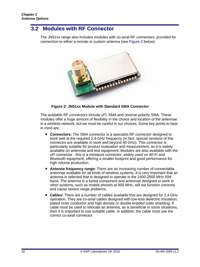
3.2 Modules with RF Connector
The JN51xx range also includes modules with co-axial RF connectors, provided for connection to either a remote or custom antenna (see Figure 2 below).
The available RF connectors include uFl, SMA and reverse polarity SMA. These modules offer a huge amount of flexibility in the choice and location of the antennae in a wireless network, but we must be careful in our choices. Some key points to bear in mind are:
Connectors: The SMA connector is a specialist RF connector designed to work well at the required 2.4-GHz frequency (in fact, special versions of this connector are available to work well beyond 40 GHz). This connector is particularly suitable for product evaluation and measurement, as it is widely available on antennae and test equipment. Modules are also available with the uFl connector - this is a miniature connector, widely used on Wi-Fi and Bluetooth equipment, offering a smaller footprint and good performance for high volume production.
Antenna frequency range: There are an increasing number of connectable antennae available for all kinds of wireless systems. It is very important that an antenna is selected that is designed to operate in the 2400-2500 MHz ISM band. The antenna is a tuned component and antennae designed to work in other systems, such as mobile phones at 900 MHz, will not function correctly and cause severe range problems.
Cables: There are a number of cables available that are designed for 2.4-GHz operation. They are co-axial cables designed with low-loss dielectric insulation, plated inner conductor and high-density or double-braided outer shielding. If cable must be used to relocate an antenna, as is beneficial in some situations, then it is important to use suitable cable. In addition, the cable must use the correct co-axial connector.
Figure 2: JN51xx Module with Standard SMA Connector
16 © NXP Laboratories UK 2013 JN-AN-1059 v1.2
Wireless Network Deployment GuidelinesApplication Note
The recommended antennae are typically low-loss, dipole types. As a general rule, this type of antenna is about 2 to 4 times more efficient than the integral ceramic type, achieving up to double the free-space range of the latter. The dipole antenna is much bigger than the tiny ceramic antenna. There are many situations in which small size is important (particularly in hand-held equipment) but, generally speaking, good performance does not come with small antenna size.
It is possible to attach an antenna directly to the module connector, but this is not recommended for situations where there could be mechanical stress on the antenna which could potentially damage the module. As with the ceramic antenna, it is important to mount the connectable antenna away from other metallic structures, obeying the same 6-cm clearance rule. It is also unlikely that the larger antennae would be placed inside the equipment case.
Tip: In order to avoid installation and (later) reliability issues, NXP recommend that cables are bought as completed and tested sub-assemblies designed for use at the relevant frequency.
Tip: NXP recommend a range of antennae for use with the JN51xx modules fitted with RF connectors - refer to the Application Note "Antennae for use with JN51xx" (JN-AN-1030).
JN-AN-1059 v1.2 © NXP Laboratories UK 2013 17

Chapter 3Antenna Options
18 © NXP Laboratories UK 2013 JN-AN-1059 v1.2

Wireless Network Deployment GuidelinesApplication Note
4. Antenna Properties and Types
This section introduces certain key antenna properties and the main types of antenna.
4.1 Antenna Directivity
Have you ever wondered why a TV satellite dish needs to be pointed very precisely in the direction of the broadcaster's satellite? The dish is a reflector antenna - radio waves arriving parallel to the axis of the antenna are collected by the dish (normally part of a paraboloid) and reflected to a common focus on the axis, where they are converted into electrical signals. This leads to a particular sensitivity to radio waves arriving from one specific direction, from one small patch of sky - the antenna is said to be highly directive. As the diameter of a dish antenna is increased, the antenna becomes more directive. Thus, a radio telescope, such as the 76-metre diameter Lovell telescope at Jodrell Bank in England, is much more directive than a satellite dish - this enables astronomers to isolate an extremely tiny patch of sky for observation, such as that encompassing a distant galaxy.
A consequence of a highly directive antenna is that it has very poor sensitivity in other directions. The sensitivity or "directivity" of an antenna can be mapped as a function of the angle of arrival of radio waves - the result is referred to as the "radiation pattern" or "polar diagram" of the antenna. An antenna with equal sensitivity in all directions will result in a spherical radiation pattern, while a highly directional antenna will have
Figure 3: A Large Directive Antenna - Lovell Radio Telescope at Jodrell Bank
JN-AN-1059 v1.2 © NXP Laboratories UK 2013 19

Chapter 4Antenna Properties and Types
a significant "main beam" or "major lobe" (as well as a number of smaller "side lobes") - these are illustrated in Figure 4 below.
The "directivity" of an antenna in a certain direction can be thought of as its sensitivity as a receiver in that direction. However, it is easier to think of directivity in terms of the relative power of the antenna in the given direction when used as a transmitter. As a numerical quantity, the directivity is expressed relative to that of an isotropic antenna - that is, an antenna which is equally sensitive (as a receiver) or radiates equally (as a transmitter) in all directions. The directivity of an isotropic antenna in any direction is defined as 1. The directivity of another antenna, in a certain direction, is then stated relative to this isotropic case, with the assumption that both antennae radiate the same total power (integrated over all directions). The directivity is expressed logarithmically in units of "dBi" - decibels, with the "i" indicating with reference to the isotropic antenna. Thus, a directivity of 20 dBi indicates that the antenna radiates 100 times more power than an isotropic antenna in the given direction.
Figure 4: Radiation Patterns for Isotropic and Directive Antennae
Isotropic Antenna Directive Antenna
20 © NXP Laboratories UK 2013 JN-AN-1059 v1.2

Wireless Network Deployment GuidelinesApplication Note
4.2 Antenna Issues and Types
Wireless networks do not normally require the use of highly directive antennae, but there are a number of properties of the antennae that must be considered. These issues are summarised below:
A single antenna must function well for all likely angles of arrival of radio energy from other nodes.
The antenna must, in most cases, be small enough to be compatible with a small radio node.
Local radio regulatory rules may restrict the size of the antenna by setting a limit on the allowed gain (see Section 4.3).
Where an antenna can be oriented in a particular direction, it is likely that its direction setting will not be very precise.
The main types of antenna are considered in the subsections below.
4.2.1 Isotropic Antenna
As already mentioned, an "isotropic" antenna radiates equally in all directions as a transmitter, and is equally sensitive in all directions as a receiver. The antenna radiation pattern is simply a sphere with directivity of unity in all directions, as shown in Figure 4. It is not a real-world antenna and exists only in theory. Its significance is that it provides a reference point for all other antennae - often, antenna directivity and gain are specified in units of "dBi", which defines the relative directivity or gain of the real-world antenna against the theoretical isotropic antenna.
JN-AN-1059 v1.2 © NXP Laboratories UK 2013 21

Chapter 4Antenna Properties and Types
4.2.2 Half-Wave Dipole Antenna
Figure 5 below shows the radiation pattern of a half-wave dipole antenna (for the Antenna Factor ANT-2.4-CW-RCT-RP antenna, in this example). Note that the dipole radiates in a similar way to the isotropic case close to the horizontal, but has virtually no radiation at the vertical.
Figure 5: Half-Wave Dipole Antenna
Z
22 © NXP Laboratories UK 2013 JN-AN-1059 v1.2

Wireless Network Deployment GuidelinesApplication Note
4.2.3 Yagi Antenna
The Yagi antenna is highly directive. Figure 6 below shows its radiation pattern (for the Telex 2.4-GHz WLAN antenna, in this example). Notice that there is a direction in which the antenna radiates with almost ten times the power of the isotropic antenna. However, this directivity comes at the expense of power radiated in other directions and for considerably higher cost. Antennae of this type will give significantly more range, but only in one direction, and therefore are only really suitable for point-to-point links (see Section 6.5). Another potential benefit is that the system is less susceptible to interfering signals from outside the main beam of the antenna.
Figure 6: Yagi Antenna
Z
Z
JN-AN-1059 v1.2 © NXP Laboratories UK 2013 23

Chapter 4Antenna Properties and Types
4.3 Antenna Gain
Antenna gain is simply the antenna directivity taking into account any inefficiencies in the antenna, and is usually expressed in dBi (as for directivity - see above). Antenna inefficiencies can originate in the antenna structure itself, as well as the RF feed and, if fitted, the cable to the antenna. This becomes significant with very small antennae, particularly ceramic types. However, for well engineered antennae with good RF feeds, it is permissible to consider directivity and gain to be interchangeable.
Antennae with positive gains boost the range of the radio system, in the direction that the gain is quoted. Once again, considering the case of the two satellites, as described in Equation 1, if we now assume they have antennae with particular gains in the relevant directions then Equation 1 can be adjusted as shown below:
where R = Achievable range, in metres = Free-space wavelength, in metresPtx = Transmitter power, in WattsPrx = Receiver sensitivity, in WattsG1 and G2 = Linear antenna gains for Satellite 1 and Satellite 2 respectively
Often it is simpler to use decibel (dB) quantities, which are routinely quoted in datasheets - in this case, Equation 2 is rewritten as:
where R = Achievable range, in metres = Free-space wavelength, in metresptx = Transmitter power, in dBmprx = Receiver sensitivity, in dBmg1 and g2 = Antenna gains for Satellite 1 and Satellite 2, in dBi, respectively
Note that range increases with higher antenna gain, higher transmit power and better receiver sensitivity.
Note: Most antennae datasheets quote peak gain in the most favourable direction, so it is worth checking the radiation patterns to see how much variation in gain occurs in different directions.
R
4------
PtxG1G2
Prx---------------------= Equation 2
R
4------ 10
g1 g2 ptx prx–+ +
20------------------------------------------- = Equation 3
24 © NXP Laboratories UK 2013 JN-AN-1059 v1.2
Wireless Network Deployment GuidelinesApplication Note
4.4 Antenna Polarisation
A radio transmission is linearly polarised - that is, the electric and magnetic fields in the radio waves are in fixed orthogonal planes (each containing the direction of wave propagation). This is because the transmitting antenna has a dominant polarisation which, by convention, is defined as horizontal or vertical. The range of the broadcast is optimised by using a receiving antenna with the same polarisation, particularly when there is a line-of-sight or directional antennae are used. The use of cross-polarised antennae will result in reduced range. Normally, an antenna will have guidelines and/or markings that show the dominant polarisation. Where there is no line-of-sight, polarisation becomes less important, as signals reflected from different objects arrive with widely differing polarisations (multipath propagation is described in Chapter 5).
4.5 Antenna Commissioning
If we now look at the concept of directivity in terms of commissioning a wireless network, there are two scenarios to consider:
Non-engineered: A node is installed in a changing network in which the node is required to communicate with other nodes in various directions. These directions may be known or unknown, but they may also change with time as nodes are added or moved. This scenario requires that all directions are covered by the antenna's radiation pattern and, therefore, the use of an antenna with low directivity, such as the half-wave dipole shown in Figure 5.
Engineered: A node is installed in a fixed network to communicate with one or a number of fixed nodes. This situation can benefit from using a directive antenna, if the antenna can be oriented correctly during installation. However, subject to a lower range performance, this type of network can still use a non-directive antenna.
Tip: JN51xx modules with integral ceramic antenna are ideal for non-engineered installations (the module's supporting data contains installation guidelines, but these are broad). JN51xx modules with RF connector can be used in either type of installation, with appropriate antennae.
Tip: NXP recommend the use of half-wavelength dipoles which, at 2.45 GHz, are relatively small antennae but effective performers.
JN-AN-1059 v1.2 © NXP Laboratories UK 2013 25

Chapter 4Antenna Properties and Types
26 © NXP Laboratories UK 2013 JN-AN-1059 v1.2

Wireless Network Deployment GuidelinesApplication Note
5. Reflections, Obstructions and Multipath
In a free-space situation with no nearby obstructions, radio waves have a clear path between two wireless network nodes. In reality, this situation is only approximately realised when nodes are very close together, perhaps several metres, and there are no other structures nearby. More often, there are obstructions in the direct line-of-sight as well as structures around the nodes giving rise to absorption of radio energy and multiple reflections. This situation is illustrated in Figure 7 below.
This situation is extremely complex and varies with the type of installation. In fact, radio waves will propagate through brick walls, concrete floors and plasterboard partitions, among other materials, but a loss will be incurred (as compared with free-space propagation). Depending on the thickness, moisture content and angle of incidence, a wall may allow between 1/100 and ¼ of the radio power to pass through. In radio terms, this loss is significant but not a disaster. However, a metal panel or metallised glass window will not allow much radio power to pass through - the vast majority of the incident power will be reflected, as if the panel were a mirror (beware that plasterboard is often backed with metal foil). This can be a serious issue since losses can build up very quickly. However, some radio power may propagate through small holes (apertures) in the panel or around metal edges through the process of diffraction.
Figure 7: A Simple Multipath Situation
JN-AN-1059 v1.2 © NXP Laboratories UK 2013 27

Chapter 5Reflections, Obstructions and Multipath
Thick layers of building material absorb a lot of radio energy - for example, very thick stone walls. Such absorption also poses problems for overground-to-underground communication.
For particularly difficult environments, it may be advisable to request advice on antenna types and placement from NXP or external specialists.
An IEEE 802.15.4-based wireless network will not work underwater. In addition, nodes operating in wet conditions (i.e. in heavy rainfall) may exhibit some degradation. In most cases, water droplets on or close to the antenna are more serious than the rain itself, so care should be taken to ensure that enclosures shed water well.
Apart from a few situations, it is very difficult to exclude ALL radio power from an area. Thus, a radio link can be made to work under most situations with some careful planning, but there are many situations to consider and radio path losses vary widely. For example:
A large public building may have few obstructions between nodes, but large amounts of metallic panelling that cause reflections.
A small domestic installation may have numerous brick walls between nodes in individual rooms.
An office building may have metallised dry-wall partitions together with mezzanine ceilings.
A system in an open-air car park will enjoy relatively few obstructions and may benefit from elevated gantry sites.
Given the huge variation in situations, many researchers have studied the effects of the environment on 2.4-GHz radio wave propagation. The techniques used have varied from deterministic models using ray-tracing techniques to statistical approaches using curve fitting to measured data. These are used to determine the siting of individual radio devices.
For some systems, site surveys are used to perform radio link measurements (for example, using NXP’s PER test software - see the above Tip) specific to the installation before individual nodes are placed in their final positions. This technique has been used widely for wireless PBX equipment (cordless telephones) and professional proprietary radio systems.
It is assumed that a typical installation of a wireless network is unlikely to have the benefit of a detailed site survey or propagation modelling techniques. The placing of individual nodes will be largely non-engineered, as they will normally be sensors or switches with positions determined by other factors. However, a ZigBee PRO network will have the benefit of mesh networking, where the important factor becomes the maximum allowable space between individual nodes.
Tip: In these situations, it is advisable to check the available performance using a site survey tool, such as the Packet Error Rate (PER) software available for NXP's JN516x evaluation kits - refer to the Application Note “Packet Error Rate Testing for JN516x” (JN-AN-1175).
28 © NXP Laboratories UK 2013 JN-AN-1059 v1.2

Wireless Network Deployment GuidelinesApplication Note
6. Deployment Guidelines
The following sections offer some guidelines as a starting point for planning purposes.
6.1 General Guidelines
One of the most important factors when placing any node is its height above its immediate environment. As a general rule in buildings, head height or above is preferred, and the higher the better for maximising range. If nodes must be placed in positions very close to the floor, such as a radiator thermostat, then the range may be reduced by between 50% and 90%.
It is also important to consider the environment close to the antenna. If possible, avoid placing the node where there are obscuring objects (such as metal pillars, posts or signs) near to the antenna - a close object obscures a wider range of solid angle.
6.2 Multipath and Fade Margins
It is a fact of life that radio reflections will be present in most 2.4-GHz radio paths. When the path between two radio antennae is assessed, the transmitted signal can follow many different paths to arrive at the receive antenna. One path may be direct, but other paths may involve multiple reflections from walls or metal obstructions. These are "multiple paths", normally shortened to "multipath". This is a common experience in analogue TV systems, where it can cause a "ghost" on a television image. Where there is no line-of-sight, it is multipath (i.e. the scattered signal) that propagates the radio energy, and here multipath therefore provides a useful service. However, multipath gives rise to power fluctuations about an average value depending on location and, in a busy area, time. This is illustrated in Figure 8 below, which shows the variation in signal strength over time in a laboratory environment with people moving around. In basic terms, the strong signals regions (or peaks) are present when the multipath signals arrive in phase and add up - this is known as constructive interference. In the low signal regions (nulls), the multipath signals arrive out of phase and cancel each other out - this is known as destructive interference.
Figure 8: Multipath Fading Over Time
2 4 6 8 10 12 14 16 18 20-15
-10
-5
0
5
10
0
Elapsed Time [s]
Sig
nal L
eve
l (ab
out
me
an)
[dB
]
JN-AN-1059 v1.2 © NXP Laboratories UK 2013 29

Chapter 6Deployment Guidelines
Depending on the strength of the direct signal compared with the reflected signal, this variation can be serious. In a non-LOS situation at 2.45 GHz, it is possible to move the receive antenna only 3 to 4 cm and see signal levels vary from 6 dB to –20 dB when compared with the local average. This can be characterised by using a statistical multipath model, although this is rarely used in practical situations. Instead, a "fade margin" can be applied. This works by ensuring that the average signal level is well above the sensitivity of the system, allowing a "margin" of error when "fades" occur. The required size of this margin depends on the desired level of confidence. In a mesh network, it can be argued that when many alternative routes are available, moderate confidence (perhaps 50% of locations are above a certain power level) is acceptable. When the network is more sparse, the confidence level should be increased (perhaps to 75% or even 90%). A word of caution here - a law of diminishing returns applies to confidence levels - with any wireless system, to achieve a confidence level of 99.9% would probably require extremely low node spacing.
6.3 Open Space Guidelines
For an open space, a typical installation would be the provision of nodes along a perimeter fence or across a car park. In radio propagation terms, these situations are line-of-sight with little or no obstructions, and therefore do not suffer largely from multipath effects. In these situations, it is acceptable to neglect the traditional fade margin.
Using a free-space approximation is a good starting point for such situations - a range of 200-300 metres should be achievable, if each node is 2 metres or higher above the local ground. A high-power module will achieve a much larger range, but when ranges are above approximately 500 metres a point-to-point link approximation must be used.
Tip: As a typical guide, when nodes are installed, there should be about 20 dB path loss margin allowed to take fades into account and to give an acceptable level of confidence.
Tip: Another word of caution here - the height at which a node is installed is crucial to using free-space rules. In short, if the free-space approximation is applied, the nodes at transmit and receive ends must be elevated above local obstructions. This is especially important as the required range increases.
30 © NXP Laboratories UK 2013 JN-AN-1059 v1.2

Wireless Network Deployment GuidelinesApplication Note
6.4 Indoor Environment Guidelines
Following on from Chapter 5, it is certain that when a link is set up inside a building it will exhibit a shorter range than suggested by the free-space guidelines, even when a line-of-sight is present. In cluttered environments, the range reduction can be very significant.
There are many different types of environment for any model that is created to cover indoor radio propagation. However, this document has used a generalised and modified version of the models. For a guide to node spacings at different levels of confidence, refer to the publication "The Mobile Radio Propagation Channel" by David Parsons (Pentech Press 1992, ISBN0-7273-1316-9). Figure 9 plots node-to-node spacing versus confidence level for situations where there is no directional antenna and no line-of-sight present. The plot uses typical values for the JN51xx high-power and standard modules. Furthermore, in Figure 9 scenarios are considered for traversing zero, one and two floors.
The node-to-node spacings displayed in Figure 9 are very approximate. However, they do provide some guidelines for pre-planning an installation, if time permits. If this is not feasible, a simple approach of pacing out distances between nodes will bring rewards in terms of mesh reliability (for information on mesh networks, refer to Chapter 7).
JN-AN-1059 v1.2 © NXP Laboratories UK 2013 31

Chapter 6Deployment Guidelines
Figure 9: Node-to-Node Spacing for Various Modules and Confidence Levels
0.0
20.0
40.0
60.0
80.0
100.0
120.0
140.0
160.0
60% 65% 70% 75% 80% 85% 90% 95% 100%
Indoor Node to Node Spacing (metres)
Confidence Level
High Power Module Traversing 0 Floors High Power Module Traversing 1 Floors
Low Power Module Traversing 0 Floors High Power Module Traversing 2 Floors
Low Power Module Traversing 1 Floors
32 © NXP Laboratories UK 2013 JN-AN-1059 v1.2
Wireless Network Deployment GuidelinesApplication Note
6.5 Point-to-Point Link Guidelines
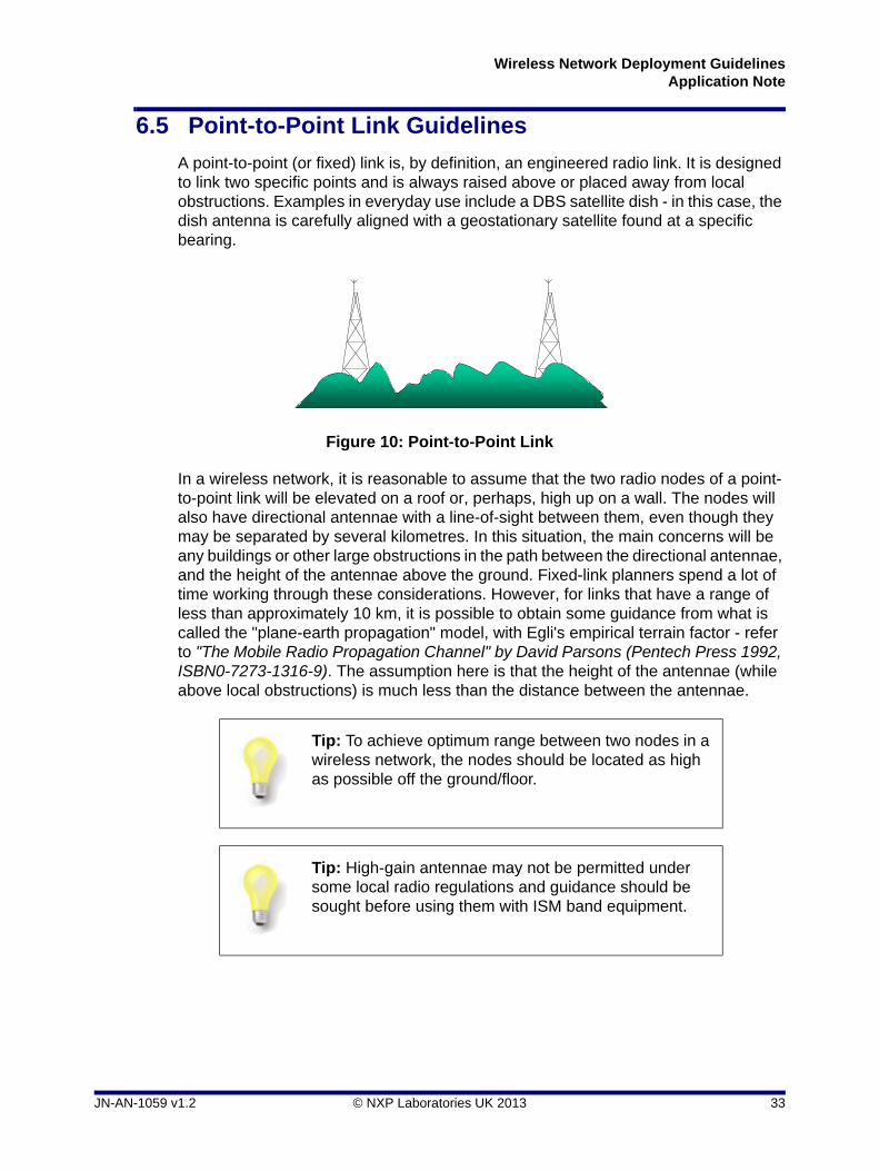
A point-to-point (or fixed) link is, by definition, an engineered radio link. It is designed to link two specific points and is always raised above or placed away from local obstructions. Examples in everyday use include a DBS satellite dish - in this case, the dish antenna is carefully aligned with a geostationary satellite found at a specific bearing.
In a wireless network, it is reasonable to assume that the two radio nodes of a point-to-point link will be elevated on a roof or, perhaps, high up on a wall. The nodes will also have directional antennae with a line-of-sight between them, even though they may be separated by several kilometres. In this situation, the main concerns will be any buildings or other large obstructions in the path between the directional antennae, and the height of the antennae above the ground. Fixed-link planners spend a lot of time working through these considerations. However, for links that have a range of less than approximately 10 km, it is possible to obtain some guidance from what is called the "plane-earth propagation" model, with Egli's empirical terrain factor - refer to "The Mobile Radio Propagation Channel" by David Parsons (Pentech Press 1992, ISBN0-7273-1316-9). The assumption here is that the height of the antennae (while above local obstructions) is much less than the distance between the antennae.
Figure 10: Point-to-Point Link
Tip: To achieve optimum range between two nodes in a wireless network, the nodes should be located as high as possible off the ground/floor.
Tip: High-gain antennae may not be permitted under some local radio regulations and guidance should be sought before using them with ISM band equipment.
Antennas are elevated clear of local obstructions
JN-AN-1059 v1.2 © NXP Laboratories UK 2013 33

Chapter 6Deployment Guidelines
34 © NXP Laboratories UK 2013 JN-AN-1059 v1.2

Wireless Network Deployment GuidelinesApplication Note
7. The Benefits of Mesh Networking
The previous chapters have given a broad overview of radio links at 2.4 GHz. One key factor that underpins any link between transmit and receive antennae is that its performance can vary widely depending on a huge number of factors. There is no guarantee that a radio link will always be possible. However, to increase the level of confidence that a link is available, the required level of radio performance increases rapidly too. In reality, the radio must either transmit more power, using a larger transmitter or transmit antenna, or exhibit a higher receive sensitivity.
A powerful way of ensuring radio communication between two nodes is provided by the mesh network topology supported by ZigBee. In a mesh network, each router node can communicate directly (single hop) with any other node within radio range. This opens up a variety of multi-hop routes to remote nodes with which communication is not directly possible. Thus, direct radio contact with the target node is not an issue in a mesh network, and neither is the availability of any particular multi-hop route, since an alternative route can normally be found. A simple mesh network is illustrated in Figure 11 below.
For further information on Mesh networks, refer to the ZigBee PRO Stack User Guide (JN-UG-3048).
Figure 11: Simple Mesh Network
JN-AN-1059 v1.2 © NXP Laboratories UK 2013 35

Chapter 7The Benefits of Mesh Networking
36 © NXP Laboratories UK 2013 JN-AN-1059 v1.2

Wireless Network Deployment GuidelinesApplication Note
8. Sharing Channels with Other Radio Systems
As mentioned earlier, the ISM band at 2.4 GHz is used by a variety of radio system types. To illustrate this issue, Figure 12 below shows the situation with respect to the now prevalent WLAN (Wireless Local Area Network) systems.
Any fixed channel system, such as WLAN, that uses the same radio channel as an IEEE 802.15.4-based network can seriously disrupt the network when handling large amounts of data. However, in most applications, it is possible to arrange that the WLAN and IEEE 802.15.4-based systems use different channels. As can be seen in Figure 12, it is usually possible to find channels that are not used by WLAN systems. To avoid interference, a channel scanning algorithm can be used in an IEEE 802.15.4-based system to ensure that the best channel is chosen.
Another widely used system that shares the ISM band at 2.4 GHz is Bluetooth. Used mainly for headsets and some peripheral connections, the Bluetooth system rapidly hops across most of the 2.4 GHz band. This may disrupt an IEEE 802.15.4-based network, but degradation in performance would be gradual.
Figure 12: ISM Band Sharing
1
Channel
2400MHz
2483.5MHz
11 12 13 14 15 16 17 18 19 20 21 22 23 24 25 26
2405 2410 2415 2420 24352425 2430 2440 2445 2450 2455 2460 2465 2470 2475 2480
Channel
2400MHz
2483.5MHz
2412 2442 2472
Channel
2400MHz
2483.5MHz
7 13
22MHz
1
2412 2437
6
2462
11
2MHz
US WLAN(IEEE 802.11b)non-overlapping
European WLAN(IEEE 802.11b)non-overlapping
IEEE 802.15.42400 MHz PHY
Channel does not overlap with WLAN in USAChannel does not overlap with WLAN in Europe
Key
JN-AN-1059 v1.2 © NXP Laboratories UK 2013 37

Chapter 8Sharing Channels with Other Radio Systems
Microwave ovens are present in many IEEE 802.15.4 operating areas and do exhibit low levels of leakage that can disrupt IEEE 802.15.4-based (or any ISM 2.4 GHz) equipment. However, the duty cycle of microwave cavity ovens is such that there is plenty of time between cooking cycles for IEEE 802.15.4 packets to be transmitted successfully.
As a general rule, for any installation, it is always worth assessing the other systems that may be installed nearby. When transmitter and receiver are close together, they couple energy very well indeed. The same rule also applies to any interfering systems. Therefore, if the situation allows, it is worth locating nodes as far away as possible from items such as Wi-Fi routers and microwave ovens. A distance of several metres may suffice, but tens of metres is preferable.
Note that international radio regulations which govern radio equipment ensure that cellphones use their allocated bands only. It is therefore highly unlikely that cellphones will interfere with IEEE 802.15.4-based equipment.
Tip: NXP provide tools to help assess the operating environment of a wireless network. The Site Survey Tool can be used to detect interference - see the Application Note “Site Survey Tool for JN516x” (JN-AN-1176). The PER Tester can be used to assess the quality of radio links - see the Application Note “Packet Error Rate Testing for JN516x” (JN-AN-1175).
38 © NXP Laboratories UK 2013 JN-AN-1059 v1.2

Wireless Network Deployment GuidelinesApplication Note
9. Deployment Checklist
The following checklist provides a summary of factors from an RF view-point that you need to consider when designing/installing a wireless network.
Choose an antenna type which is appropriate for your network:
If a node needs to receive and transmit signals in various directions, use an antenna with low directivity - NXP recommend a half-wave dipole antenna.
If a node needs to receive and transmits signals only in a specific direction, use an antenna with high directivity, such as a Yagi antenna - this solution is suitable for point-to-point links which require a large range.
Refer to Section 4.2 for details.
Ensure that the gains, transmit power and receive sensitivity of your chosen antennae are sufficient to achieve the required range - refer to Section 4.3.
Be sure to orientate the antennae such that their dominant polarisations are aligned (particularly for point-to-point links) - see Section 4.4.
Where possible, try to ensure an uninterrupted line-of-sight between nodes - be aware that the following will reduce signal strength and quality:
Obstructions (such as furniture and people) absorb, reflect and diffract radio waves.
Walls, floors and ceilings absorb and reflect radio waves - the degree of absorption depends on the thickness, structure and construction materials.
Refer to Chapter 5 for details.
If there is no line-of-sight between nodes, be aware that multipath radio propagation (through reflection and diffraction) is vital to achieve radio communication - you may be able to help produce a good multipath signal by positioning nodes such that their signals reflect off a plane surface.
When siting nodes, the following factors are useful to bear in mind:
It is normally beneficial to place nodes as high as possible (unless there are obstructions to be avoided, such as support beams and ceiling lights).
If obstructions are unavoidable, do not place a node near to an obscuring object, since a close object obscures a larger solid angle.
You can check the quality of radio communications in an installed network using a tool such as NXP’s Packet Error Rate (PER) tester - refer to the Application Note “Packet Error Rate Testing for JN516x” (JN-AN-1175).
If radio communications between some nodes prove problematic, consider implementing the network in a Mesh topology (supported by the ZigBee PRO protocol) - refer to Chapter 7 for further information.
Wireless networks based on IEEE 802.15.4 can automatically select the frequency channel with least detected activity when sampled at system start-up. If you wish to use a pre-configured channel, you should first investigate the potential interference present in the given operating environment using a suitable tool such as NXP’s Site Survey Tool - refer to the Application Note “Site Survey Tool for JN516x” (JN-AN-1176).
JN-AN-1059 v1.2 © NXP Laboratories UK 2013 39

Chapter 9Deployment Checklist
40 © NXP Laboratories UK 2013 JN-AN-1059 v1.2

Wireless Network Deployment GuidelinesApplication Note
Revision History
Version Date Comments
1.0 23-July-2007 First release
1.1 12-Feb-2009 ISM band sharing diagram modified
1.2 18-Dec-2013 JN51xx devices and supported protocols updated
JN-AN-1059 v1.2 © NXP Laboratories UK 2013 41

Wireless Network Deployment GuidelinesApplication Note
Important Notice
Limited warranty and liability - Information in this document is believed to be accurate and reliable. However, NXP Semiconductors does not give any representations or warranties, expressed or implied, as to the accuracy or completeness of such information and shall have no liability for the consequences of use of such information. NXP Semiconductors takes no responsibility for the content in this document if provided by an information source outside of NXP Semiconductors.
In no event shall NXP Semiconductors be liable for any indirect, incidental, punitive, special or consequential damages (including - without limitation - lost profits, lost savings, business interruption, costs related to the removal or replacement of any products or rework charges) whether or not such damages are based on tort (including negligence), warranty, breach of contract or any other legal theory.
Notwithstanding any damages that customer might incur for any reason whatsoever, NXP Semiconductors' aggregate and cumulative liability towards customer for the products described herein shall be limited in accordance with the Terms and conditions of commercial sale of NXP Semiconductors.
Right to make changes - NXP Semiconductors reserves the right to make changes to information published in this document, including without limitation specifications and product descriptions, at any time and without notice. This document supersedes and replaces all information supplied prior to the publication hereof.
Suitability for use - NXP Semiconductors products are not designed, authorized or warranted to be suitable for use in life support, life-critical or safety-critical systems or equipment, nor in applications where failure or malfunction of an NXP Semiconductors product can reasonably be expected to result in personal injury, death or severe property or environmental damage. NXP Semiconductors and its suppliers accept no liability for inclusion and/or use of NXP Semiconductors products in such equipment or applications and therefore such inclusion and/or use is at the customer's own risk.
Applications - Applications that are described herein for any of these products are for illustrative purposes only. NXP Semiconductors makes no representation or warranty that such applications will be suitable for the specified use without further testing or modification.
Customers are responsible for the design and operation of their applications and products using NXP Semiconductors products, and NXP Semiconductors accepts no liability for any assistance with applications or customer product design. It is customer's sole responsibility to determine whether the NXP Semiconductors product is suitable and fit for the customer's applications and products planned, as well as for the planned application and use of customer's third party customer(s). Customers should provide appropriate design and operating safeguards to minimize the risks associated with their applications and products.
NXP Semiconductors does not accept any liability related to any default, damage, costs or problem which is based on any weakness or default in the customer's applications or products, or the application or use by customer's third party customer(s). Customer is responsible for doing all necessary testing for the customer's applications and products using NXP Semiconductors products in order to avoid a default of the applications and the products or of the application or use by customer's third party customer(s). NXP does not accept any liability in this respect.
Export control - This document as well as the item(s) described herein may be subject to export control regulations. Export might require a prior authorization from competent authorities.
NXP Laboratories UK Ltd(Formerly Jennic Ltd)
Furnival StreetSheffieldS1 4QT
United Kingdom
Tel: +44 (0)114 281 2655Fax: +44 (0)114 281 2951
For the contact details of your local NXP office or distributor, refer to:
www.nxp.com
For online support resources, visit the Wireless Connectivity TechZone:
www.nxp.com/techzones/wireless-connectivity
42 © NXP Laboratories UK 2013 JN-AN-1059 v1.2