Wireless Mobile Communications: Part 2 – Mobile Ad-hoc Networks (MANET)
56
Wireless Mobile Communications: Part 2 – Mobile Ad-hoc Networks (MANET) Jae H. Kim, Ph.D. Manager/Associate Technical Fellow Boeing Phantom Works [email protected] (253) 657-7685
-
Upload
nash-mclaughlin -
Category
Documents
-
view
31 -
download
2
description
Wireless Mobile Communications: Part 2 – Mobile Ad-hoc Networks (MANET). Jae H. Kim, Ph.D. Manager/Associate Technical Fellow Boeing Phantom Works [email protected] (253) 657-7685. Outline. PART 2: Wireless LAN MAC Protocols Mobile Ad-hoc Network (MANET) Proactive Reactive - PowerPoint PPT Presentation
Transcript of Wireless Mobile Communications: Part 2 – Mobile Ad-hoc Networks (MANET)
Wireless Mobile Communications: Part 2 – Mobile Ad-hoc Networks (MANET)
Jae H. Kim, Ph.D.
Manager/Associate Technical Fellow
Boeing Phantom Works
(253) 657-7685

Outline
PART 2:
• Wireless LAN MAC Protocols
• Mobile Ad-hoc Network (MANET)
• Proactive• Reactive• Hybrid

Wireless LANMAC Protocol

Wireless Protocol Layers
Application Processing
Propagation Model Mobility
Frame Processing Radio Status/Setup
CS/RadioRTS/CTSFrame Wrapper
Ack/Flow Control
Clustering
Packet Store/Forward VC Handle
FlowControl Routing
IP Wrapper IP/Mobile IP
RSVPTransport Wrapper TCP/UDP Control
Channel
Radio
MAC Layer
Network
IP
Transport
Application
RTP Wrapper RCTP
Packet Store/Forward
Clustering
Routing
Link Layer
Application Setup
Data Plane Control Plane

Media Access Control (MAC) Layer
• MAC protocol: - Coordination and scheduling of transmissions among competing neighbors
• Goals: - Low latency, good channel utilization; best effort and real time support
• MAC layer clustering: - Aggregation of nodes in a cluster (= cell) for MAC enhancement- Different from network layer clustering, partitioning such as used for routing

• CDMA (Code Division Multiple Access)• FDMA (Frequency Division Multiple Access)• TDMA (Time Division Multiple Access)
- ALOHA- Slotted ALOHA- CSMA (Carrier Sense Multiple Access)- DAMA (Demand Assigned Multiple Access)- PRMA (Packet Reservation Multiple Access)- Reservation TDMA- MACA (Multiple Access with Collision Avoidance)- Polling
• SDMA (Space Division Multiple Access)
MAC Protocols

• MAC protocol coordinates transmissions from different stations in order to minimize/avoid collisions
(1) Random Access: CSMA, MACA
(2) Channel Partitioning: TDMA, FDMA, CDMA
(3) “Taking turns”: Polling
• Goal is efficient, fair,
simple, decentralized
Multiple Access

Random Access
• A node transmits at random (i.e., no a priory coordination among nodes) at full channel data rate
• If two or more nodes “collide,” they retransmit at random times
• The random access MAC protocol specifies how to detect collisions and how to recover from them (via delayed retransmissions, for example)
• Examples of random access MAC protocols:
(a) Slotted ALOHA – 36% throughput
(b) ALOHA – 18% throughput
(c) CSMA and CSMA/CD

Slotted ALOHA
• Time is divided into equal size slots (= full packet size)• a newly arriving station transmits a the beginning of the next
slot• if collision occurs (assume channel feedback, eg the receiver
informs the source of a collision), the source retransmits the packet at each slot with probability P, until successful.
• Success (S), Collision (C), Empty (E) slots• S-ALOHA is channel utilization efficient; it is fully decentralized

Pure (unslotted) ALOHA
• Slotted ALOHA requires slot synchronization
• A simpler version, pure ALOHA, does not require slots
• A node transmits without awaiting for the beginning of a slot
• Collision probability increases (packet can collide with other packets which are transmitted within a window twice as large as in S-Aloha)
• Throughput is reduced by one half, i.e., S= 1/2e
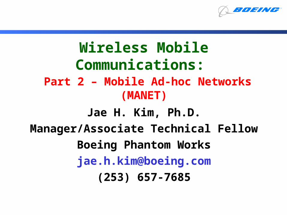
Carrier Sense Multiple Access (CSMA)
• CSMA: listen before transmit. If channel is sensed busy, defer transmission
• Persistent CSMA: retry immediately when channel becomes idle (this may cause instability)
• Non persistent CSMA: retry after random interval• Note: collisions may still exist, since two stations
may sense the channel idle at the same time ( or better, within a “vulnerable” window = round trip delay)
• In case of collision, the entire packet transmission time is wasted

Collision Detection
• CSMA/CD: carrier sensing and deferral like in CSMA. But, collisions are detected within a few bit times.
• Transmission is then aborted, reducing the channel wastage considerably.
• Typically, persistent transmission is implemented
• CSMA/CD can approach channel utilization =1 in LANs (low ratio of propagation over packet transmission time)
• Collision detection is easy in wired LANs (eg, E-net): can measure signal strength on the line, or code violations, or compare tx and receive signals
• Collision detection cannot be done in wireless LANs (the receiver is shut off while transmitting, to avoid damaging it with excess power)

• Sense channel idle for DISF (Distributed Inter Frame Space)- transmit frame (no Collision Detection)- receiver returns ACK after SIFS (Short Inter Frame Space)
• If channel sensed busy, then binary backoff
• NAV: Network Allocation Vector (min time of deferral)
IEEE 802. 11 MAC - CSMA Protocol

• CSMA inefficient in presence of hidden terminals
• Hidden terminals: A and B cannot hear each other because of obstacles or signal attenuation; so, their packets collide at B
• Solution? CSMA/CA (Collision Avoidance)
Hidden Terminal Effect

• CTS “freezes” stations within range of receiver (but possibly hidden from transmitter); this prevents collisions by hidden station during data
• RTS and CTS are very short: collisions during data phase are thus very unlikely (similar effect as Collision Detection)
• Note: IEEE 802.11 allows CSMA, CSMA/CA and “polling” from AP
Collision Avoidance

Access methods
• MAC-DCF CSMA/CA (mandatory)- Collision avoidance via randomized “back-off” mechanism- Minimum distance between consecutive packets- ACK packet for acknowledgements (not for broadcasts)
• MAC-DCF w/ RTS/CTS (optional)- Distributed Foundation Wireless MAC- Avoids hidden terminal problem
• MAC- PCF (optional)- Access point polls terminals according to a list
IEEE 802.11 - MAC Layer

• Priorities– defined through different inter frame spaces– no guaranteed, hard priorities– SIFS (Short Inter Frame Spacing)
• highest priority, for ACK, CTS, polling response– PIFS (PCF IFS)
• medium priority, for time-bounded service using PCF– DIFS (DCF, Distributed Coordination Function IFS)
• lowest priority, for asynchronous data service
t
medium busySIFS
PIFS
DIFSDIFS
next framecontention
direct access if medium is free DIFS
802.11 - MAC layer (cont.)

– station ready to send starts sensing the medium (Carrier Sense based on CCA, Clear Channel Assessment)
– if the medium is free for the duration of an Inter-Frame Space (IFS), the station can start sending (IFS depends on service type)
– if the medium is busy, the station has to wait for a free IFS, then the station must additionally wait a random back-off time (collision avoidance, multiple of slot-time)
– if another station occupies the medium during the back-off time of the station, the back-off timer stops (fairness)
t
medium busy
DIFSDIFS
next frame
contention window(randomized back-offmechanism)
slot timedirect access if medium is free DIFS
IEEE 802.11 MAC - CSMA/CA

• Sending unicast packets– station has to wait for DIFS before sending data
– receivers acknowledge at once (after waiting for SIFS) if the packet was received correctly (CRC)
– automatic retransmission of data packets in case of transmission errors
t
SIFS
DIFS
data
ACK
waiting time
otherstations
receiver
senderdata
DIFS
contention
IEEE 802.11 MAC - CSMA/CA (cont.)

• Sending unicast packets– station can send RTS with reservation parameter after waiting for DIFS
(reservation determines amount of time the data packet needs the medium)
– acknowledgement via CTS after SIFS by receiver (if ready to receive)
– sender can now send data at once, acknowledgement via ACK
– other stations store medium reservations distributed via RTS and CTS
t
SIFS
DIFS
data
ACK
defer access
otherstations
receiver
senderdata
DIFS
contention
RTS
CTSSIFS SIFS
NAV (RTS)NAV (CTS)
IEEE 802.11 MAC - RTS/CTS

• IEEE 802.11 DCF: Congestion control achieved by dynamically choosing the contention window, CW
• When transmitting a packet, choose a backoff interval in the range [0,CW]– cw is contention window
• Count down the backoff interval when medium is idle– Count-down is suspended if medium becomes busy
• When backoff interval reaches 0, transmit RTS
IEEE 802.1 MAC - DCF

IEEE 802.11 MAC – DCF (Cont.)
B1 and B2 are backoff intervalsat nodes 1 and 2CW = 31
data
waitB1 = 5
B2 = 15
B1 = 25
B2 = 20
data
waitB2 = 10
Example

• The time spent counting down backoff intervals is a part of MAC overhead
• Choosing a large CW leads to large backoff intervals and can result in larger overhead
• Choosing a small CW leads to a larger number of collisions (when two nodes count down to 0 simultaneously)
Congestion Avoidance

• Since the number of nodes attempting to transmit simultaneously may change with time, some mechanism to manage congestion is needed
• IEEE 802.11 DCF: Congestion control achieved by dynamically choosing the contention window CW
Congestion Control

• When a node fails to receive CTS in response to its RTS, it increases the contention window– cw is doubled (up to an upper bound)
• When a node successfully completes a data transfer, it restores CW to CWmin
Binary Exponential Backoff in DCF

Channel Partitioning (e.g., CDMA)
• CDMA (Code Division Multiple Access): exploits spread spectrum (DS or FH) encoding scheme
• unique “code” assigned to each user; I.e., code set partitioning• Used mostly in wireless broadcast channels (cellular, satellite,etc)• All users share the same frequency, but each user has own
“chipping” sequence (i.e., code)• Chipping sequence like a mask: used to encode the signal• encoded signal = (original signal) x (chipping sequence)• decoding: inner product of encoded signal and chipping sequence
(note: the inner product is the sum of the component-by-component products)
• To make CDMA work, chipping sequences must be chosen orthogonal to each other (i.e., inner product = 0)

CDMA Encode/Decode

CDMA (cont.)
CDMA Properties:• protects users from interference and jamming (in WW II)• protects users from radio multipath fading • allows multiple users to “coexist” and transmit
simultaneously with minimal interference (if codes are “orthogonal”)
• requires “chip synch” acquisition before demodulation• requires careful transmit power control to avoid “capture”
by near stations in near-far situations• FAA requires use of SS (with limits on tx power) in the
Unlicensed Spectrum region (ISM), e.g., 900 MHz and 2.4 GHz (WaveLANs)
• CDMA used in Qualcomm cellphones (channel efficiency improved by factor of 4 with respect to TDMA)

• Frequency spectrum sliced into frequency subbands (e.g., 125 subbands in a 25 MHz range)
• Time is subdivided into slots; each slot can carry several bits (slow FH)
• A typical packet covers several time slots• A transmitter changes frequency slot by slot
(frequency hopping) according to unique, predefined sequence; all users are clock and slot synchronized
• Ideally, hopping sequences are “orthogonal” (i.e., non overlapped); in practice, some conflicts may occur
Frequency Hopping (FH)

Mobile Ad-Hoc Networks (MANET)
Routing Protocols

• Distance Vector:– Destination-sequenced distance vector (DSDV), Bellman-Ford– Routing control overhead linearly increasing with network size– Convergence problems (count to infinity); potential loops
• Link State:– Open Shortest Path First (OSPF)– Link update flooding overhead caused by frequent topology changes
Not scalable to network size and mobility …
Proactive, Table Driven Routing

0
5
1
2
4
3
Routing table at node 5 :
Tables grow linearly with # nodes
Control overhead grows with network size and mobility
Destination Next Hop Distance
0 2 3
1 2 2
… … …
Distance Vector

• At node 5, based on the link state pkts, topology table is constructed:
• Dijkstra’s Algorithm can then be used for the shortest path
0
5
1
2
4
3
{1}
{0,2,3}
{1,4}
{2,4}
{2,3,5}
{1,4,5}
0 1 2 3 4 5
0 1 1 0 0 0 0
1 1 1 1 1 0 0
2 0 1 1 0 1 1
3 0 1 0 1 1 0
4 0 0 1 1 1 1
5 0 0 1 0 1 1
Link State Routing

• Routes are established “on demand” as requested by the source
• Only the active routes are maintained by each node
• Channel/Memory overhead is minimized• Two leading methods for route discovery:
source routing and backward learning (similar to LAN interconnection routing)
Reactive, On-Demand Routing

Routing Protocol Choices?
OSPFv2 is one of the most heavily used IGPs in the Internet today
Commercially, we have alternatives:• Cisco EIGRP (proprietary, in Distance Vector
class of protocols)• RIP (legacy Distance Vector, considered
inferior for large networks)• IS-IS (OSI link-state protocol, many of same
issues as with OSPFv2)

What is OSPFv2?
• A “link state” routing protocol for unicast traffic
• Simple concept:– Assign costs to links– Give every router a complete map of the
network– Execute a shortest path calculation for
every destination– Build a routing table with next-hop
information for all destinations

OSPFv2 Area Hierarchy
• OSPFv2 uses an “area hierarchy” to summarize groups of nodes– The backbone is called “Area 0”– Every additional area must attach to the
backbone– Routes to different areas are summarized
(aggregated) before re-distribution– Cost of area hierarchy is loss of precision in
the routes, complexity, and topology restrictions
• OSPFv2 also uses route summarization between “autonomous systems”– This is method of scaling in ADNS

Basic OSPFv2 Operation
• Routers transmit “Hello” messages every 10 seconds to each neighbor– Hello messages also contain a list of
neighbors from whom Hellos have been received
– If you see yourself in your neighbor’s Hello message, you know you have a 2-way link
– Peer routers then synchronize their databases
• Routers use a reliable flooding algorithm to disseminate link and network information

OSPFv2 Problems
• Flooding of “link state advertisements” causes overhead to grow with a) number of nodes, b) mobility
• Hello message traffic over slow links• Convergence time (operationally it is a lot
larger than one would expect) and route “flapping”
• Difficult for different areas to peer with one another

OSPFv2 over MANET?
• No interface type defined for wireless, broadcast-based networks– “Ethernet”-like interface (broadcast) does not
function correctly in wireless network– Point-to-multipoint interface creates too much
overhead (does not capitalize on broadcast capability)
• No support for Quality-of-Service-based link metrics (for load balancing)– Used to be in the protocol specification, but
was removed

Other Alternatives
• The Internet Engineering Task Force (IETF) is considering the standardization of new “Mobile Ad-hoc Network (MANET)” routing protocols
– Optimized for wireless operation– Various strategies for scaling to large
networks– Designed for most severe of NBN conditions
(when regular infrastructure breaks down or is non-existent)

MANETInstrumentation
TraditionalInstrumentation Architecture
• MANET provides connectivity across
battlefield w/o large infrastructure enables geometric pairing allows arbitration of engagements
w/in target’s subnet provides channel to report position/
location of players, casualtyassessment results
3. reportresults
2. arbitrate
1. shoot
What is MANET ?

• Mobility
• Need to scale to large numbers (100’s to 1000's up to 10, 000’s)
• Unreliable radio channel (e.g., fading, external interference)
• Limited bandwidth
• Limited power
• Need multimedia applications (QoS)
Wireless Multihop Routing

Placeholder for
mobile ad-hoc networking Applications
(animation)

• Proactive: Conventional table-driven routing– Optimized Link State Routing (OLSR)– Destination Sequenced Distance Vector (DSDV)– Fisheye State Routing (FSR)– Source Tree Adaptive Routing (STAR)– Hierarchical State Routing (HSR)
• Reactive: On-Demand routing:– Ad-hoc On-Demand Distance Vector (AODV)– Dynamic Source Routing (DSR)– Temporarily Ordered Routing Algorithm (TORA)– Location Assisted Routing (LAR)
• Hybrid Routing:– Zone routing
Mobile Ad-hoc Routing Protocols
OLSR Protocol
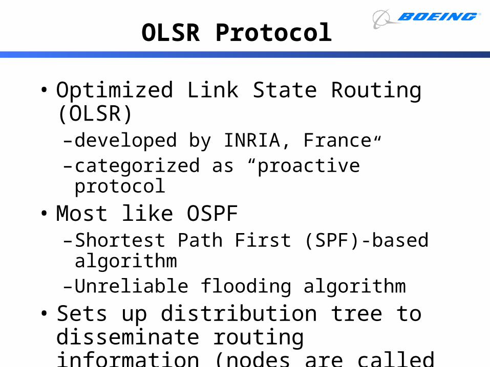
• Optimized Link State Routing (OLSR)–developed by INRIA, France–categorized as “proactive” protocol
• Most like OSPF–Shortest Path First (SPF)-based algorithm–Unreliable flooding algorithm
• Sets up distribution tree to disseminate routing information (nodes are called Multipoint Relays)

OLSR Example
•20 nodes
•100 bi-directional links (not shown)
•19 tree links (shown)
•16 leaves (not filled)
•4 non-leaf nodes
•Only 4 non-leaf nodes forward updates generated by the source
•In flooding, all 20 nodes would forward updates.
source

AODV Routing Protocol
• Ad-hoc on-demand distance vector– Developed by Perkins, Royer, Das– categorized as “reactive” MANET protocol
• Unknown routes are queried for by a flooding algorithm
• Recently used routes are cached for future use
• Several implementations exist, and extensions for QoS and IPv6 defined

AODV Example
destination
source
destination
RREP reverses successful flooding path
RREQ flooded with increasing scope
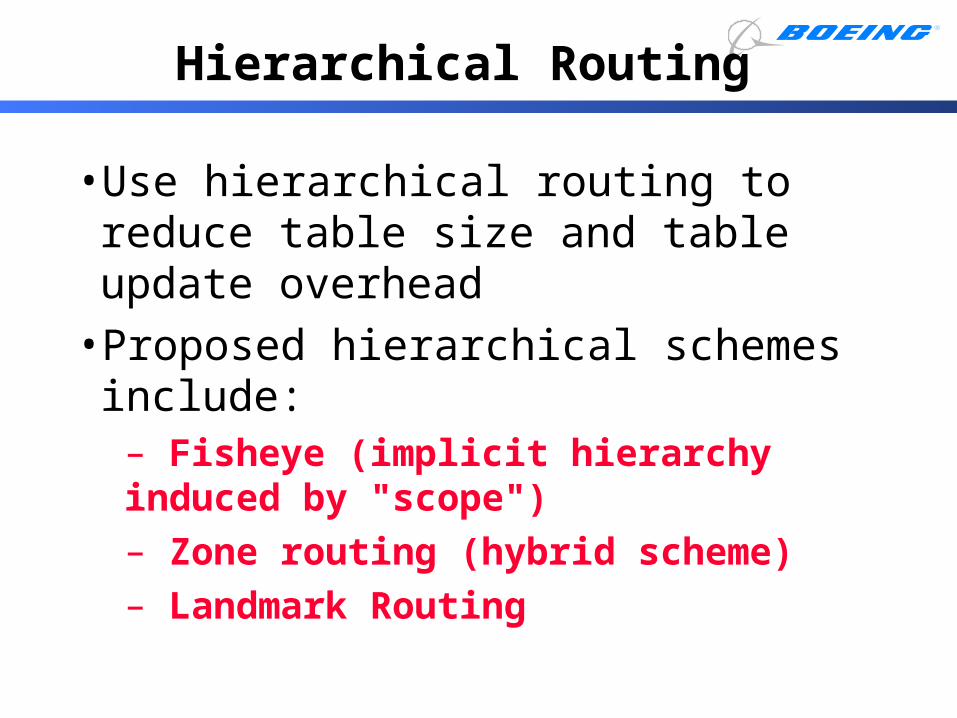
• Use hierarchical routing to reduce table size and table update overhead
• Proposed hierarchical schemes include:– Fisheye (implicit hierarchy induced by "scope")– Zone routing (hybrid scheme)– Landmark Routing
Hierarchical Routing

• Topology data base at each node– Similar to link state (e.g., OSPF)
• Routing information is periodically exchanged with neighbors only ( “Global” State Routing)
– Similar to distance vector, but exchange entire topology matrix
• Routing update frequency decreases with distance to destination
– Higher frequency updates within a close zone and lower frequency updates to a remote zone
– Highly accurate routing information about the immediate neighborhood of a node; progressively less detail for areas further away from the node
Fisheye State Routing

1
2
3
4
5
67
8
9
9
10
11
12
14 1516 17
18 19
20
21
2223
2425
26
27
28
29
30
31
3234
35
36
Hop=1
Hop=2
Hop>2
13
Scope of Fisheye

0
5
1
2
4
3
0:{1}1:{0,2,3}2:{5,1,4}3:{1,4}4:{5,2,3}5:{2,4}
101122
LST HOP
0:{1}1:{0,2,3}2:{5,1,4}3:{1,4}4:{5,2,3}5:{2,4}
212012
LST HOP
0:{1}1:{0,2,3}2:{5,1,4}3:{1,4}4:{5,2,3}5:{2,4}
221101
LST HOP
Message Reduction in FSR

• Logical subnet: group of nodes with functional affinity with each other (e.g., they move together)
• Node logical address = <subnet, host>
• A Landmark is elected in each subnet
• Every node keeps Fisheye Link State table/routes to neighbors up to hop distance N
• Every node maintains routes to all Landmarks
Landmark Routing Protocol
Logical Subnet
Landmark

Landmark Routing (cont.)
• A packet to local destination is routed directly using Fisheye tables
• A packet to remote destination is routed to corresponding Landmark based on logical addr
• Once the packet gets within Landmark scope, the direct route is found in Fisheye tables
• Benefits: dramatic reduction of both routing overhead and table size; scalable to large networks
Landmark
Logical Subnet

References
• References- UCLA Course note, “Ad-hoc Wireless Routing,” CS 218- Fall 2002.
- UCLA Course note, “Ad-hoc Nets – MAC Layer: Part 1,” CS 218- Fall 2002.
- UCLA Course note, “Ad-hoc Nets – MAC Layer: Part 2,” CS 218- Fall 2002.
• Books- James D. Solomon, Mobile IP The Internet Unplugged, Prentice Hall, 1998.
- Charles E. Perkins, Mobile IP Design Principles and Practices, Addison-Wesley, 1998.
- Christian Huitema, Routing in the Internet, Prentice Hall, 2000.
- Jochen Schiller, Mobile Communications, Addison-Wesley, 2000.
- Charles E. Perkins, Ad-Hoc Networking, Addison-Wesley, 2001.
• IETF Working Group URLhttp://www.ietf.org/html.charters/mobileip-charter.html


![An Analysis Platform for Mobile Ad Hoc (MANET) … Analysis Platform for Mobile Ad Hoc Network (MANET) Scenario Execution Log Data. ... top left [refer to Fig.1]), ...](https://static.fdocuments.us/doc/165x107/5afa43fd7f8b9aac248f96f4/an-analysis-platform-for-mobile-ad-hoc-manet-analysis-platform-for-mobile.jpg)